JP6200780B2 - Lane recognition determination device - Google Patents
Lane recognition determination device Download PDFInfo
- Publication number
- JP6200780B2 JP6200780B2 JP2013230228A JP2013230228A JP6200780B2 JP 6200780 B2 JP6200780 B2 JP 6200780B2 JP 2013230228 A JP2013230228 A JP 2013230228A JP 2013230228 A JP2013230228 A JP 2013230228A JP 6200780 B2 JP6200780 B2 JP 6200780B2
- Authority
- JP
- Japan
- Prior art keywords
- white line
- line candidate
- candidate point
- point
- lane
- Prior art date
- Legal status (The legal status is an assumption and is not a legal conclusion. Google has not performed a legal analysis and makes no representation as to the accuracy of the status listed.)
- Active
Links
Images


Description
本発明は、自車走行路の前方を撮影した画像データに基づき内側誘導線が認識されているか否かの信頼度を判定する車線認識判定装置に関する。 The present invention relates to a lane recognition determination apparatus that determines the reliability of whether or not an inner guide line is recognized based on image data obtained by photographing the front of a host vehicle traveling road.
従来、高速道路等の走行において、自車両前方の走行環境を検出し、検出した走行環境データに基づいて、自車走行レーンの左右を区画する走行車線を検出し、この走行車線に沿って自車両を自動走行させる車線維持制御や、認識した車線位置から自車両が逸脱すると予測される場合には警告を発して、運転者に注意を促す車線逸脱警報等の運転支援装置が知られている。 Conventionally, in traveling on an expressway or the like, a traveling environment in front of the host vehicle is detected, and a traveling lane that divides the left and right of the traveling lane is detected based on the detected traveling environment data. There are known driving support devices such as a lane departure control for automatically driving a vehicle, and a lane departure warning that warns the driver when the vehicle is predicted to depart from the recognized lane position. .
自車両を走行車線に沿って正確に走行させるためには、この走行車線の位置を正確に推定する必要がある。この走行車線位置を推定する手段としては、車両に搭載されているカメラ等のイメージセンサ(以下、「車載カメラ」と称する)で検出した自車両前方の走行環境に基づき、路面と白線との輝度差から白線のエッジを検出し、この白線のエッジから走行車線位置を推定する技術が知られている。 In order for the host vehicle to travel accurately along the travel lane, it is necessary to accurately estimate the position of the travel lane. As a means for estimating the traveling lane position, the brightness of the road surface and the white line is determined based on the traveling environment in front of the host vehicle detected by an image sensor such as a camera mounted on the vehicle (hereinafter referred to as “vehicle camera”). A technique is known in which the edge of a white line is detected from the difference and the traveling lane position is estimated from the edge of the white line.
ところで、高速道路上の走行車線は、走行レーンを区画する左右の走行車線のみならず、カーブ路等には、走行車線とその内側の誘導線(いわゆるドットライン)とからなる二重白線が描かれている場合がある。白線のエッジを路面との輝度差により検出する技術では、道路内側の白線が外側の白線よりも輝度差が明確に現れるため、二重白線では、内側誘導線の内側エッジに基づいて車線を推定する場合が多い。 By the way, the driving lane on the expressway is not only the left and right driving lanes that divide the driving lane, but also on curved roads, a double white line consisting of a driving lane and an inner guide line (so-called dot line) is drawn. May be. In the technology that detects the edge of the white line based on the difference in brightness from the road surface, the white line on the road has a clearer brightness difference than the white line on the outside, so for the double white line, the lane is estimated based on the inner edge of the inner guide line. There are many cases to do.
例えば、特許文献1(特開2012−58984号公報)には車線候補点のプロット位置が、二重白線の入口(開始端)では走行車線の内側エッジから誘導線の内側エッジに切換り、切換り後の点列に基づいて車線を推定する技術が開示されている。 For example, in Patent Document 1 (Japanese Patent Laid-Open No. 2012-58984), the plot position of the lane candidate point is switched from the inner edge of the traveling lane to the inner edge of the guide line at the double white line entrance (start end). A technique for estimating a lane based on a subsequent point sequence is disclosed.
上述したように、特許文献1に開示されている技術では、二重白線の入口(開始端)では、車線候補点の検出位置が内側誘導線の内側エッジに切換ってしまうため、この切換わりタイミングが明確ではない。又、同文献では、二重白線の入口を検出した場合、今回の演算時を基準として設定時間幅前におけるパラメータ係数の点列から設定時間進み、後の予測パラメータを設定するに際し、この設定時間幅を長くし、過去のパラメータ係数の点列を多くすることで、安定して車線を推定することができるようにしている。
As described above, in the technique disclosed in
しかし、当該文献に開示されている技術では、二重白線の入口(開始端)を検出した場合、過去のデータを多く取り込む必要があるため、応答遅れが生じ易い。又、二重白線の入口が検出されると、車線候補点が内側車線に自動的に切換わってしまうため、これが、例えば、走行車線に沿って形成された轍に存在する水溜まり、走行車線に沿って存在する残雪、或いは補修跡のエッジを誘導線の内側エッジと誤認識した場合、その後の車線推定が不安定となってしまう不具合がある。 However, in the technique disclosed in this document, when the entrance (starting end) of the double white line is detected, it is necessary to capture a lot of past data, so that a response delay is likely to occur. In addition, when the entrance of the double white line is detected, the lane candidate point is automatically switched to the inner lane, and this is, for example, a pool of water that exists in the eaves formed along the traveling lane and the traveling lane. If the remaining snow along the edge or the edge of the repair mark is misrecognized as the inner edge of the guide line, the subsequent lane estimation becomes unstable.
本発明は上記事情に鑑み、二重白線の入口(開始端)を検出して車線候補点が内側誘導線の内側エッジに切換わる際のタイミングを明確にし、しかも、内側誘導線とノイズ成分とを明確に区分することのできる車線認識判定装置を提供することを目的とする。 In view of the above circumstances, the present invention clarifies the timing when the lane candidate point is switched to the inner edge of the inner guide line by detecting the entrance (starting end) of the double white line, and further, the inner guide line, the noise component, and the like. It is an object of the present invention to provide a lane recognition determination apparatus that can clearly classify a vehicle.
本発明による車線認識判定装置は、自車走行路の前方を撮影した画像上の左右の各白線検出領域内で水平方向に延在する複数の検索ライン毎に輝度差によりエッジ点を抽出するエッジ点抽出手段と、前記エッジ点抽出手段で抽出したエッジ点の点列に基づきハフ変換によりハフ直線を求め、該ハフ直線に基づいて、自車走行路を区画する区画線を検出する所定幅の白線候補点抽出領域を設定する白線候補点抽出領域設定手段と、前記白線候補点抽出領域よりも画像上中央側に外れた領域のエッジ点を第0白線候補点として抽出すると共に、該第0白線候補点の数を算出する第0白線候補点数算出手段と、前記第0白線候補点数算出手段で算出した前記第0白線候補点の数、及び分布に基づき前記区画線よりも画像上中央側に描かれている内側誘導線の認識信頼度を判定する誘導線認識信頼度判定手段とを備える。 The lane recognition determination apparatus according to the present invention extracts an edge point based on a luminance difference for each of a plurality of search lines extending in the horizontal direction within each of the left and right white line detection areas on an image taken in front of the host vehicle travel path. Based on the point extraction means and the point sequence of the edge points extracted by the edge point extraction means, a Hough straight line is obtained by Hough transformation, and based on the Hough straight line, a demarcation line that divides the own vehicle traveling path is detected. A white line candidate point extraction region setting unit for setting a white line candidate point extraction region, and an edge point of a region that is located on the image center side of the white line candidate point extraction region is extracted as the 0th white line candidate point. 0th white line candidate point number calculating means for calculating the number of white line candidate points, the number of the 0th white line candidate point values calculated by the 0th white line candidate point number calculating means, and the center side on the image side of the lane marking based on the distribution Inside depicted in And a guide line recognition reliability determining means for determining the recognition reliability of the conductor.
本発明によれば、自車走行路の前方を撮影した画像から輝度差により抽出したエッジ点の点列に基づきハフ変換によりハフ直線を求め、このハフ直線に基づいて、自車走行路を区画する区画線を検出する所定幅の白線候補点抽出領域を設定し、この白線候補点抽出領域よりも画像上中央側に外れた領域のエッジ点を第0白線候補点として抽出すると共に、この第0白線候補点の数を算出し、この第0白線候補点の数、及び分布に基づき区画線よりも画像上中央側に描かれている内側誘導線の認識信頼度を判定するようにしたので、認識信頼度が低い場合は、内側誘導線による白線形状の推定が行われず、従って、内側誘導線とノイズ成分とを明確に区分することができると共に、車線候補点が内側誘導線の内側エッジに切換わるタイミングを明確化させることができ、又、過去のパラメータ係数の点列を多く取り入れていないため、二重白線の入口(開始端)を検出して車線候補点が内側誘導線の内側エッジに切換わる際に応答遅れが生じることもない。 According to the present invention, a Hough straight line is obtained by Hough transformation based on a sequence of edge points extracted by a luminance difference from an image taken in front of the own vehicle traveling road, and the own vehicle traveling road is partitioned based on the Hough straight line. A white line candidate point extraction region having a predetermined width for detecting a dividing line to be detected is set, and an edge point of an area that is out of the white line candidate point extraction region on the center side of the image is extracted as a zeroth white line candidate point. Since the number of 0 white line candidate points is calculated and the number of 0th white line candidate points and the distribution are determined, the recognition reliability of the inner guide line drawn on the center side of the image from the partition line is determined. When the recognition reliability is low, the white line shape is not estimated by the inner guide line, so the inner guide line and the noise component can be clearly distinguished, and the lane candidate point is the inner edge of the inner guide line. The timing to switch to Since it does not incorporate many points in the past parameter coefficients, it is possible to detect the entrance (starting end) of the double white line and switch the lane candidate point to the inner edge of the inner guide line. There is no response delay.
以下、図面に基づいて本発明の一実施形態を説明する。図1において、符号1は自動車等の車両(自車両)であり、この車両1に、自車両前方の環境情報に基づいて車両を操向(操舵制御、ブレーキ制御等)する運転支援装置2が搭載されている。この運転支援装置2は、例えば、車載イメージセンサとしての車載カメラ3、ステレオ画像認識装置4、運転支援手段としての機能を備える制御ユニット5等で構成されている。
Hereinafter, an embodiment of the present invention will be described with reference to the drawings. In FIG. 1,
又、自車両1には、自車速を検出する車速センサ11、ヨーレートを検出するヨーレートセンサ12、運転支援制御の各機能のON/OFF切換等を行うメインスイッチ13、ステアリングホイール14に連設するステアリング軸14aに対設されて舵角を検出する舵角センサ15、運転者によるアクセルペダル踏込量(アクセル開度)を検出するアクセル開度センサ16等が設けられている。更に、このステアリング軸14aに運転者のステアリング操作をアシストするパワーステアリングモータ17が連設されている。
The
又、車載カメラ3は、ステレオ光学系として、CCDやCMOS等の固体撮像素子を備えるメインカメラとサブカメラとからなる左右1組のカラーカメラで構成されている。この各カメラは、それぞれフロントガラス背面の車室内の天井に一定の間隔を持って取り付けられ、車外の対象を異なる視点からステレオ撮影し、その画像データをステレオ画像認識装置4に送信する。尚、以下の説明において、ステレオ撮影された画像のうちメインカメラで撮影した画像を基準画像、サブカメラで撮影した画像を比較画像と称する。
The in-
ステレオ画像認識装置4は、先ず、基準画像を4×4画素の小領域に分割し、それぞれの小領域の輝度或いは色のパターンを比較画像と比較して対応する領域を見つけ出し、基準画像全体に渡る距離分布を求める。更に、ステレオ画像認識装置4は、基準画像上の各画素について隣接する画素との輝度差を調べ、これらの輝度差がしきい値を超えているものをエッジ点として抽出すると共に、抽出した画素(エッジ点)に距離情報を付与することで、距離画像(距離情報を備えたエッジ点の分布画像)を生成する。そして、ステレオ画像認識装置4は、生成した距離画像に対して周知のグルーピング処理を行い、予め記憶していた3次元的な枠(ウインドウ)と比較することで、自車前方の白線、側壁、立体物等を認識する。
First, the stereo
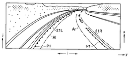
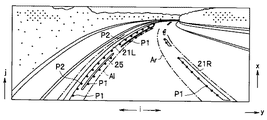
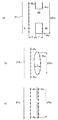
ここで、本実施形態において認識対象となる白線とは、例えば、自車走行レーンを区画する左右の白線(区画線)21L,21Rや、この区画線21L,21Rと、その内側に描かれている内側誘導線22(図5、図9参照)からなる、いわゆる二重白線等、道路上に延在して自車走行レーンを示すために描かれた線の総称である。各白線の形態としては、実線、破線等を問わず、更に、黄色線等を含む。又、本実施形態の白線の形状認識においては、道路上に実在する白線が二重白線であっても、左右それぞれ単一の近似線で近似して各白線の内側エッジに沿った形状を推定するものとする。
Here, the white lines to be recognized in the present embodiment are, for example, drawn on the inner sides of the left and right white lines (partition lines) 21L and 21R that divide the own vehicle traveling lane and the
この白線形状の推定に際し、ステレオ画像認識装置4は、例えば、図5、図7、図9に示すように、今回撮影した1つのフレームの基準画像データ上に白線検出領域Al,Ar(以下、Al,ArをAと総称して説明する)を設定し、この各白線検出領域A内で、1画素ピッチの水平検索ラインi上を下側(自車両の手前側)から遠方となる上方向(j方向)に1画素ピッチずつオフセットしながら画素を順次車幅方向内側(画像上中央側)から外側に向けて検索し輝度変化を調べる。そして、ステレオ画像認識装置4は、各白線検出領域A内の各水平検索ライン上において、輝度が暗から明に所定以上変化するエッジ点が存在する場合には、最初のエッジ点を第1のエッジ点P1として検出し、次のエッジ点を第2のエッジ点P2として検出する。
In the estimation of the white line shape, the stereo
又、ステレオ画像認識装置4は、検出した第1,第2のエッジ点P1,P2の各点列に基づいて自車走行路を区画する白線が走行車線のみ(以下、単白線と称する)か、二重白線であるかを判定する。
In addition, the stereo
そして、白線が単白線であると判定した場合、ステレオ画像認識装置4は、第1のエッジ点P1の点列に基づいてハフ直線Hl,Hr(以下、Hl,HrをHと総称して説明する)を演算し、このハフ直線Hに基づいて定めた白線候補点抽出領域Adl,Adr(以下、Adl,AdrをAdと総称して説明する)内に存在する第1のエッジ点P1を白線候補点Psとして抽出する。尚、詳細については後述するが、図19(a)に示すように、白線候補点抽出領域Adはハフ直線Hを挟んで内側に所定幅α1、外側に所定幅α2を有しており、内側の所定幅α1は、図9に示す区画線21L,21Rの内側エッジから内側誘導線22の内側エッジまでの距離よりも短く、且つ区画線21L,21Rの線幅よりも長い値に設定されている。
If it is determined that the white line is a single white line, the stereo
一方、白線が二重白線であると判定した場合、ステレオ画像認識装置4は、検出された第2のエッジ点P2に基づいて演算したハフ直線Hを基準として定めた白線候補点抽出領域Adよりも内側に存在する第1のエッジ点P1を白線候補点Psとして抽出する。上述したように、白線候補点抽出領域Adの内側の所定幅α1は、区画線21L,21Rの内側エッジから内側誘導線22の内側エッジまでの距離よりも短く設定されているため、二重白線の場合、第1のエッジ点P1は白線候補点抽出領域Adから外れた内側に存在する。
On the other hand, when it is determined that the white line is a double white line, the stereo
又、ステレオ画像認識装置4は、前フレーム以前に抽出した白線候補点Psの座標と自車の移動量とに基づいて自車後方の設定距離(例えば、20〜30[m])内における後方白線候補点Ps_preを推定し、抽出した白線候補点Ps及び推定した後方白線候補点Ps_preの点列に基づいて白線の形状を近似する。
Further, the stereo
制御ユニット5には、ステレオ画像認識装置4で認識された自車両1前方の走行環境情報が入力される。更に、制御ユニット5には、自車両1の走行情報として、車速センサ11で検出した車速V、ヨーレートセンサ12で検出したヨーレートγ等が入力されると共に、運転者による操作入力情報として、メインスイッチ13からのON/OFF信号、舵角センサ15で検出した舵角θst、アクセル開度センサ15で検出したアクセル開度θacc等が入力される。
The
そして、例えば、運転者によるメインスイッチ13の操作を通じて、運転支援制御の機能の1つである車線逸脱防止制御や、車線維持支援制御等の実行が指示されると、制御ユニット5は、ステレオ画像認識装置4で認識した走行車線(白線形状の近似線)に基づいて逸脱判定ラインを設定すると共に、自車走行路を推定する。そして、車線逸脱防止制御では、自車両が逸脱判定ラインから逸脱傾向にあると判断した場合に、自車両を車線中央側へ戻す操向(操舵制御やブレーキ制御)を行い、又、車線維持支援制御は、走行車線内に目標走行位置を設定し、自車両が目標走行位置に沿って走行するように操向(操舵制御やブレーキ制御)を行う。
For example, when an instruction to execute lane departure prevention control or lane keeping support control, which is one of the functions of the driving support control, is given through the operation of the
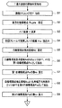
上述したステレオ画像認識装置4で実行される白線形状認識処理は、具体的には、図2、図3に示す二重白線移行開始判定処理ルーチン、及び、図4に示す白線形状推定処理ルーチンに従って行われる。
Specifically, the white line shape recognition processing executed by the stereo
図2、図3に示すフローチャートは、1フレーム毎に実行され、先ず、ステップS1で、車載カメラ3で撮影された画像(基準画像)からエッジ点Pを検出する。すなわち、ステレオ画像認識装置4は、図5,図7、図9に示すように、画像上に設定された白線検出領域A内の水平検索ライン毎に車幅方向内側(画像の幅方向中央)から外側(図のi方向)に向けて輝度の変化を調べ、外側の画素の輝度が内側の画素の輝度に対して相対的に高く、且つ、その変化量を示す輝度の微分値がプラス側の設定しきい値以上のエッジ点PH(白線開始点)を検索する。続いて、内側の画素の輝度に対して相対的に低く、且つ、その変化量を示す輝度の微分値がマイナス側の設定しきい値以下となるエッジ点PL(白線終了点)を検索する(図11参照)。
The flowcharts shown in FIGS. 2 and 3 are executed for each frame. First, in step S1, an edge point P is detected from an image (reference image) taken by the in-
そして、白線検出領域A内にひとつのエッジ点PH(白線開始点)が検出された場合、当該エッジ点PHを第1のエッジ点P1として設定する。或いは、白線検出領域A内に2以上のエッジ点PHが検出された場合は、例えば、最初のエッジ点PHを第1のエッジ点P1、次のエッジ点PHを第2のエッジ点P2として設定する。更に、ステレオ画像認識装置4は、検出した各エッジ点PHに距離画像上の距離情報を付与することにより、各エッジ点PHの座標を実空間上の座標に変換する(図6,図8、図10参照)。尚、このステップS1での処理が、本発明のエッジ点抽出手段に対応している。
When one edge point PH (white line start point) is detected in the white line detection area A, the edge point PH is set as the first edge point P1. Alternatively, when two or more edge points PH are detected in the white line detection area A, for example, the first edge point PH is set as the first edge point P1, and the next edge point PH is set as the second edge point P2. To do. Furthermore, the stereo
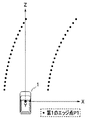
その後、ステップS2へ進むと、前フレーム以前に抽出された白線候補点Psの座標と自車両1の移動量とに基づいて後方白線候補点Ps_preを推定する。ここで、自車両1の移動量は、例えば、自車速Vとヨー角θ(ヨーレート(dθ/dt)から計算される角度)を用いて求めることが可能である。例えば、図13に示すように、フレームレートをΔtとすると、自車両1が1フレームで自車両1‘方向、すなわち、X軸方向及びZ軸方向に移動する移動量Δx,Δzは、以下の(1),(2)式から求めることができる。
Thereafter, when proceeding to step S2, the rear white line candidate point Ps_pre is estimated based on the coordinates of the white line candidate point Ps extracted before the previous frame and the movement amount of the
Δx=V・Δt・sinθ …(1)
Δz=V・Δt・cosθ …(2)
従って、例えば、図14に示すように、前フレームで検出された白線候補点Ps_oldの座標を(xold,zold)とし、当該白線候補点Ps_oldが現フレームの白線候補点(後方白線候補点)Ps_preに移動したと推定した場合、その座標(xpre,zpre)は、以下の(3),(4)式から求めることができる。すなわち、座標(xpre,zpre)は、座標(xold,zold)に対して車両移動量Δx,Δzを減算した後、現在のフレームにおける車両固定座標系(X’,Z’)への座標変換を行うことで求めることができる。
Δx = V · Δt · sin θ (1)
Δz = V · Δt · cos θ (2)
Therefore, for example, as shown in FIG. 14, the coordinates of the white line candidate point Ps_old detected in the previous frame are (xold, zold), and the white line candidate point Ps_old is the white line candidate point (back white line candidate point) Ps_pre of the current frame. When it is estimated that it has moved, the coordinates (xpre, zpre) can be obtained from the following equations (3) and (4). That is, the coordinates (xpre, zpre) are obtained by subtracting the vehicle movement amounts Δx, Δz from the coordinates (xold, zold) and then converting the coordinates to the vehicle fixed coordinate system (X ′, Z ′) in the current frame. It can be obtained by doing.
xpre=(xold−Δx)・cosθ−(zold−Δz)・sinθ …(3)
zpre=(xold−Δx)・sinθ+(zold−Δz)・cosθ …(4)
これにより、例えば、図15に示すように、自車両1の後方の設定距離内における後方白線候補点Ps_preを推定することができる。
xpre = (xold−Δx) · cos θ− (zold−Δz) · sin θ (3)
zpre = (xold−Δx) · sin θ + (zold−Δz) · cos θ (4)
Thereby, for example, as shown in FIG. 15, the rear white line candidate point Ps_pre within the set distance behind the
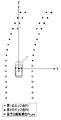
その後、ステップS3へ進むと、第1のエッジ点P1の点列を用いてハフ変換によりハフ直線Hを求める。ここで、ハフ直線Hの求め方について例示する。先ず、図16に示すように、点列を構成する各第1のエッジ点P1のそれぞれに対し、第1のエッジ点P1を通る直線hの傾きを0°〜180°まで所定の角度Δθ毎に変化させ、以下の(5)式に基づいて各角度θにおける原点Oから直線hまでの距離(垂線の長さ)であるオフセット量ρを求める。 Thereafter, when the process proceeds to step S3, a Hough straight line H is obtained by Hough transformation using the point sequence of the first edge points P1. Here, an example of how to obtain the Hough straight line H will be described. First, as shown in FIG. 16, with respect to each of the first edge points P1 constituting the point sequence, the inclination of the straight line h passing through the first edge point P1 is set to a predetermined angle Δθ from 0 ° to 180 °. Based on the following equation (5), an offset amount ρ, which is the distance (vertical length) from the origin O to the straight line h at each angle θ, is obtained.
ρ=x・cosθ+z・sinθ …(5)
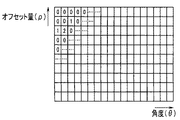
そして、各エッジ点P1について求めた各角度θとオフセット量ρとの関係を、図17に示すハフ平面(θ,ρ)上の該当箇所に度数として投票(投影)する。その後、ハフ平面(θ,ρ)上の度数が最も大きくなる角度θとオフセット量ρとの組み合わせを抽出し、当該角度θとオフセット量ρとを用いて(5)式で規定される直線(ハフ直線H)を求める。尚、今回求めたハフ直線Hは、次回のルーチン実行時に、ハフ直線Holdとして、後のステップS4で読込まれる。
ρ = x · cos θ + z · sin θ (5)
Then, the relationship between each angle θ obtained for each edge point P1 and the offset amount ρ is voted (projected) as a frequency on a corresponding portion on the Hough plane (θ, ρ) shown in FIG. Thereafter, a combination of the angle θ and the offset amount ρ with the largest frequency on the Hough plane (θ, ρ) is extracted, and the straight line (5) is defined using the angle θ and the offset amount ρ ( Find the Hough straight line H). The Hough straight line H obtained this time is read as a Hough straight line Hold in the subsequent step S4 when the next routine is executed.
次いで、ステップS4へ進むと、前回のフレーム画像に基づいて求めたハフ直線Holdを読込み、続く、ステップS5で、このハフ直線Holdを基準として所定幅の白線候補点抽出領域Adを設定する。図18(a)、図19(a)に示すように、白線候補点抽出領域Adは、ハフ直線Hを挟む内側と外側に、所定幅α1,α2が設定されている。内側の所定幅α1は、上述したように、図9に示す二重白線の区画線21L,21Rの内側エッジから内側誘導線22の内側エッジまでの間の距離よりも短く、且つ、区画線21L(或いは21R)の線幅よりも長い値に設定されている。尚、二重白線の区画線21L,21R、内側誘導線22の幅、及び区画線21L,21Rの内側エッジと内側誘導線22の外側エッジとの間隔は予め規定されている。
Next, when proceeding to Step S4, the Hough straight line Hold obtained based on the previous frame image is read, and at Step S5, a white line candidate point extraction region Ad having a predetermined width is set with reference to the Hough straight line Hold. As shown in FIGS. 18A and 19A, in the white line candidate point extraction region Ad, predetermined widths α1 and α2 are set inside and outside the Hough straight line H. As described above, the inner predetermined width α1 is shorter than the distance between the inner edge of the double white
一方、外側の所定幅α2は、区画線21L(或いは21R)の線幅よりも長い値に設定されており、本実施形態では、所定幅α1と同じ幅に設定されている。従って、二重白線の場合、図19(a)に示すように、内側誘導線22の内側エッジを検出する第1のエッジ点P1は。この白線候補点抽出領域Adから外れた内側に点在する。尚、図18,図19Iは、左側区画線21Lが記載されているが、右側区画線21Rに対しても同様に白線候補点抽出領域Adが設定される。又、ステップS3〜5での処理が、本発明の白線候補点抽出領域設定手段に対応している。
On the other hand, the outer predetermined width α2 is set to a value longer than the line width of the
その後、ステップS6へ進むと、白線候補点抽出領域Ad内に存在する第1,第2のエッジ点P1,P2を第1白線候補点Ps1として抽出し(図18(b)参照)、続く、ステップS7で、第1白線候補点Ps1の数n1(以下、第1白線候補点数n1と称す)を算出する。 Thereafter, when proceeding to step S6, the first and second edge points P1 and P2 existing in the white line candidate point extraction area Ad are extracted as the first white line candidate point Ps1 (see FIG. 18B), and then, In step S7, the number n1 of first white line candidate points Ps1 (hereinafter referred to as first white line candidate point number n1) is calculated.
そして、ステップS8へ進み、白線候補点抽出領域Adよりも車幅方向内側に存在するエッジ点P1を、第0白線候補点Ps0として抽出し(図18(b)参照)、続く、ステップS9で、この第0白線候補点Ps0の数n0(以下、第0白線候補点数n0と称す)を算出する。尚、このステップS8,S9での処理が、本発明の第0白線候補点数算出手段に対応している。 Then, the process proceeds to step S8, where the edge point P1 existing on the inner side in the vehicle width direction from the white line candidate point extraction area Ad is extracted as the 0th white line candidate point Ps0 (see FIG. 18B), and then in step S9. Then, the number n0 of the 0th white line candidate points Ps0 (hereinafter referred to as the 0th white line candidate point number n0) is calculated. The processes in steps S8 and S9 correspond to the 0th white line candidate point number calculating means of the present invention.
その後、ステップS10へ進み、このステップS10〜ステップS33で、二重白線移行開始タイミング、すなわち、第0白線候補点Ps0に基づいて後述する車線モデル式の構築を開始するタイミングを判定する。尚、このステップS10〜S33での処理が、本発明の誘導線認識信頼度判定手段に対応している。 Thereafter, the process proceeds to Step S10, and in Steps S10 to S33, the double white line transition start timing, that is, the timing to start construction of a lane model formula described later is determined based on the 0th white line candidate point Ps0. The processing in steps S10 to S33 corresponds to the guide wire recognition reliability determination means of the present invention.
上述したステップS5では、白線候補点抽出領域Adを、前回のフレームに基づいて設定したハフ直線Holdを基準として設定している。こうすることで、例えば、図7に示すように、区画線21Lの内側に、水溜まりや残雪、或いは補修跡等のノイズ成分25が、区画線21Lに沿って存在していても、白線候補点Ps1に基づいて車線モデル式が求められるため、ノイズ成分25の影響を受け難い。反面、ノイズ成分25ではない、二重白線の内側誘導線22が検出された場合であっても、車線モデル式を構築する白線候補点が内側誘導線22の内側エッジを検出する第0白線候補点Ps0へ移行しない不都合がある。
In step S5 described above, the white line candidate point extraction region Ad is set based on the Hough straight line Hold set based on the previous frame. In this way, for example, as shown in FIG. 7, even if a
又、遠方(フレーム上では画面上部)にカーブ入口が検出されており、そのカーブ入口に二重白線が描かれていても、遠方のカーブ入口では区画線21L,21Rと内側誘導線22とが一本の白線のように映るため、内側誘導線22が区画線21L,21Rと誤認識され易く、その場合、車線モデル式を構築する白線候補点がいつ、内側誘導線22の内側エッジを検出する第0白線候補点Ps0へ移行したかのタイミングを判別することができない不都合が生じる。
In addition, even if a curve entrance is detected far away (upper part of the screen on the frame) and a double white line is drawn at the entrance of the curve, the
そのため、ステップS10〜ステップS31において、第0白線候補点Ps0が検出された場合、それが内側誘導線22の内側エッジを検出したものであるか否か、換言すれば、内側誘導線22が認識されているか否かの信頼度を判別する。そして、内側誘導線22の内側エッジを検出したものであるとの信頼度が高い場合、車線モデル式を構築する白線候補点を第0白線候補点Ps0に切換える。
Therefore, when the 0th white line candidate point Ps0 is detected in step S10 to step S31, whether or not it is the detection of the inner edge of the
すなわち、先ず、ステップS10では、前回のフレーム画像に基づく演算において、二重白線の入口(開始端)らしき成分(内側誘導線らしきもの)が検出されているか否かを調べる。二重白線の入口(開始端)らしき成分が検出されているか否かは、例えば、前回の演算時に第0白線候補点Ps0が検出されているか否かで判定する。 That is, first, in step S10, it is checked whether or not a component that seems to be the entrance (start end) of the double white line (what seems to be the inner guide line) has been detected in the calculation based on the previous frame image. Whether or not a component that seems to be the entrance (starting end) of a double white line is detected is determined, for example, by whether or not the 0th white line candidate point Ps0 has been detected during the previous calculation.
そして、二重白線の入口らしき成分が検出されている場合は、ステップS11へ進み、二重白線信頼度判定カウンタのカウント値(以下、単に「カウント値」と称する)Cnをインクリメントして(Cn←Cn+1)、ステップS13へ進む。又、二重白線の入口らしき成分が検出されていない場合、ステップS12へ分岐し、カウント値Cnをデクリメントして(Cn←Cn−1)、ステップS13へ進む。二重白線信頼度判定カウンタのカウント値Cnは、内側誘導線らしき成分が、はたして内側誘導線22か否かを判定する認識信頼度を表す値である。
If a component that seems to be an entrance of a double white line is detected, the process proceeds to step S11, and the count value (hereinafter simply referred to as “count value”) Cn of the double white line reliability determination counter is incremented (Cn ← Cn + 1), the process proceeds to step S13. If no double white line-like component is detected, the process branches to step S12, decrements the count value Cn (Cn ← Cn-1), and proceeds to step S13. The count value Cn of the double white line reliability determination counter is a value representing the recognition reliability for determining whether or not the component that seems to be the inner guide line is the
ステップS13では、今回算出した第0白線候補点数n0と所定しきい値SLn0とを比較し、n0>SLn0の場合、ステップS14へ進み、カウント値Cnをインクリメントして(Cn←Cn+1)、ステップS16へ進む。又、n0≦SLn0の場合、ステップS15へ分岐し、カウント値Cnをデクリメントして(Cn←Cn−1)、ステップS16へ進む。このしきい値SLn0は、今回の演算で、内側誘導線22の内側エッジが検出されているか否か判定する値である。
In step S13, the currently calculated 0th white line candidate point number n0 is compared with a predetermined threshold value SLn0. If n0> SLn0, the process proceeds to step S14, the count value Cn is incremented (Cn ← Cn + 1), and step S16. Proceed to If n0 ≦ SLn0, the process branches to step S15, decrements the count value Cn (Cn ← Cn−1), and proceeds to step S16. This threshold value SLn0 is a value for determining whether or not the inner edge of the
ステップS16へ進むと、1フレームの画像中で検出した最初の第0白線候補点Ps0から最後の第0白線候補点Ps0までの距離ΔPs0(図12参照)と設定閾値SLΔPs0とを比較して、第0白線候補点Ps0の分布が、内側誘導線22の内側エッジを検出したものであると判別するに充分か否かを調べる。そして、ΔPs0>SLΔPs0の場合、第0白線候補点Ps0の分布は充分であると判定し、ステップS17へ進み、カウント値Cnをインクリメントして(Cn←Cn+1)、ステップS19へ進む。又、ΔPs0≦SLΔPs0の場合、ステップS18へ分岐し、カウント値Cnをデクリメントして(Cn←Cn−1)、ステップS19へ進む。
Proceeding to step S16, the distance ΔPs0 (see FIG. 12) from the first 0th white line candidate point Ps0 detected in the image of one frame to the last 0th white line candidate point Ps0 is compared with the set threshold value SLΔPs0. It is checked whether or not the distribution of the 0th white line candidate point Ps0 is sufficient to determine that the inner edge of the
ステップS19へ進むと、第0白線候補点Ps0を検出した内側誘導線とみなされる成分の幅f(平均値)を検出し、この幅fが所定下限幅fSと所定上限幅fLとの間に収まっているか否かを調べる。図12(a)に示すように、白線誘導線22の幅fは、10〜15[cm]程度に予め規定されている。従って、この規定値を含む値に所定下限幅fSと所定上限幅fLとを設定することで、幅fから、第0白線候補点Ps0は内側誘導線22の内側エッジを検出したものであるか否かを判別することができる。尚、幅fは、図11に示すように、輝度の変化により検出されたエッジ点PH(白線開始点)の水平方向の平均値とエッジ点PL(白線終了点)の水平方向の平均との差である。
In step S19, the width f (average value) of the component regarded as the inner guide line from which the 0th white line candidate point Ps0 is detected is detected, and the width f is between the predetermined lower limit width fS and the predetermined upper limit width fL. Find out if it fits. As shown to Fig.12 (a), the width f of the white
そして、fS<f<fLの場合、ステップS20へ進み、カウント値Cnをインクリメントして(Cn←Cn+1)、ステップS22へ進む。又、f≦fS、或いはf≧fLの場合は、ステップS21へ分岐し、カウント値Cnをデクリメントして(Cn←Cn−1)、ステップS22へ進む。 If fS <f <fL, the process proceeds to step S20, the count value Cn is incremented (Cn ← Cn + 1), and the process proceeds to step S22. If f≤fS or f≥fL, the process branches to step S21, the count value Cn is decremented (Cn ← Cn-1), and the process proceeds to step S22.
その結果、同12(b)に示すような幅fが所定上限幅fLよりも太い(f≧fL)、水溜まりや補修跡、及び、同図(c)に示すような区画線21Lに沿って延在する幅fが所定上限幅fLよりも細い(f≦fS)、帯状の残雪等はノイズ成分25であると判定し、カウント値Cnがデクリメントされる。尚、図12には、説明を容易にするために左側区画線21Lのみが示されているが、この左側区画線21Lを右側区画車線21Rと読み換えることで、当該右側区画車線21Rに適用することができる。
As a result, the width f as shown in FIG. 12 (b) is larger than the predetermined upper limit width fL (f ≧ fL), the water pool and the repaired trace, and the
そして、ステップS22へ進むと、区画線21Lの内側エッジを検出した第1白線候補点Ps1の水平方向の平均値と内側誘導線らしき成分の外側エッジを検出したエッジ点PLの水平方向の平均値との差から隙間m(平均値)を検出し、この隙間mが所定下限隙間mSと所定上限隙間mLとの間に収まっているか否かを調べる。図12(a)に示すように、区画線21Lの内側エッジと内側誘導線22の外側エッジとの間の隙間mは、予め10〜15[cm]程度に規定されている。従って、この規定値を含む値に所定下限隙間mSと所定上限隙間mLとを設定することで、この隙間mから、今回の第0白線候補点Ps0は内側誘導線22の内側エッジを検出したものであるか否かを判定することができる。尚、図12(a)に示すように、隙間mは、第0白線候補点Ps0の水平方向の位置座標をx0、第1白線候補点Ps1の水平方向の位置座標をx1とした場合、m=x0−(f+x1)から求められる。
Then, when proceeding to step S22, the horizontal average value of the first white line candidate point Ps1 that has detected the inner edge of the
そして、mS<m<mLの場合、ステップS23へ進み、カウント値Cnをインクリメントして(Cn←Cn+1)、ステップS25へ進む。又、m≦mS、或いはmLの場合、ステップS24へ分岐して、カウント値Cnをデクリメントし(Cn←Cn−1)、ステップS25へ進む。従って、仮に、図12(b)に示す水溜まりや補修跡の幅f、及び、同図(c)に示す残雪の幅fが、所定下限値fSと所定上限値fLとの間に収まっているとしても(fS<f<fL)、その隙間mが、所定下限隙間mSと所定上限隙間mLに収まっていなければ、ノイズ成分25の可能性があると判定し、カウント値Cnがデクリメントされる。
If mS <m <mL, the process proceeds to step S23, the count value Cn is incremented (Cn ← Cn + 1), and the process proceeds to step S25. If m ≦ m S or m L, the process branches to step S24, the count value Cn is decremented (Cn ← Cn−1), and the process proceeds to step S25. Accordingly, tentatively, the width f of the puddle or repair trace shown in FIG. 12 (b) and the width f of the remaining snow shown in FIG. 12 (c) fall within the predetermined lower limit value fS and the predetermined upper limit value fL. (FS <f <fL), if the gap m does not fall within the predetermined lower limit gap mS and the predetermined upper limit gap ml, it is determined that there is a possibility of the
その後、ステップS25へ進むと、先ず、内側誘導線らしき成分の各第0白線候補点Ps0における幅fのヒストグラムを生成し、所定ピーク幅以上を示す幅fの数(ピーク数)fpekを求め、このピーク数fpekの第0白線候補点数n0に対する比率(ピーク比率)を求める(fpek/n0)、このピーク比率fpek/n0と所定ピーク判定閾値SLfpとを比較する。 After that, when proceeding to step S25, first, a histogram of the width f at each 0th white line candidate point Ps0 of the component that seems to be the inner guide line is generated, and the number (peak number) fpek of the width f indicating a predetermined peak width or more is obtained. A ratio (peak ratio) of the peak number fpek to the zeroth white line candidate point number n0 is obtained (fpek / n0), and the peak ratio fpek / n0 is compared with a predetermined peak determination threshold SLfp.
そして、fpek/n0>SLfpの場合、ステップS26へ進み、カウント値Cnをインクリメントして(Cn←Cn+1)、ステップS28へ進む。又、fpek/n0≦SLfpの場合、ステップS27へ分岐し、カウント値Cnをデクリメントして(Cn←Cn−1)、ステップS28へ進む。内側誘導線22は幅fがほぼ一定であるため、ピーク比率fpek/n0は比較的高い値が示される。これに対し、例えば、図12(c)に示す帯状の残雪は、幅fが一定ではなく、従って、たとえ、上述したステップS19において幅f(平均値)が、所定下限幅fSと所定上限幅fLとの間に収まっていたとしても、ピーク比率fpek/n0がピーク判定閾値SLfpを超えていなければ、ノイズ成分25の可能性があると判定し、カウント値Cnがデクリメントされる。
If fpek / n0> SLfp, the process proceeds to step S26, the count value Cn is incremented (Cn ← Cn + 1), and the process proceeds to step S28. If fpek / n0 ≦ SLfp, the process branches to step S27, the count value Cn is decremented (Cn ← Cn−1), and the process proceeds to step S28. Since the
次いで、ステップS28へ進むと、各第1白線候補点Ps1の平均輝度AVps1と各第0白線候補点Ps0の平均輝度AVps0との差分(輝度差)AVpsを求め(AVps←AVps1−AVps0)、この輝度差AVpsと所定輝度差判定閾値SLpsとを比較する。内側誘導線22の内側エッジを検出した第0白線候補点Ps0の輝度は、区画線21L(21R)の内側エッジを検出した第1白線候補点Ps1の輝度よりも明るいため、内側誘導線22が検出されている場合、輝度差AVpsは小さい値となる。又、第0白線候補点Ps0の輝度が高い場合、内側誘導線22が明確に表れていることを示しているため、輝度差AVpsが小さい値を示す場合、車線モデル式は、単白線を検出する第1白線候補点Ps1から二重白線の内側誘導線22を検出する第0白線候補点Ps0に切換えて構築した方が好ましい。
Next, in step S28, a difference (luminance difference) AVps between the average luminance AVps1 of each first white line candidate point Ps1 and the average luminance AVps0 of each zeroth white line candidate point Ps0 is obtained (AVps ← AVps1-AVps0). The brightness difference AVps is compared with a predetermined brightness difference determination threshold SLps. The brightness of the 0th white line candidate point Ps0 that detected the inner edge of the
そして、AVps<SLpsの場合、ステップS29へ進み、カウント値Cnをインクリメントして(Cn←Cn+1)、ステップS31へ進む。又、AVps≧SLpsの場合、ステップS30へ分岐し、カウント値Cnをデクリメントして(Cn←Cn−1)、ステップS31へ進む。 If AVps <SLps, the process proceeds to step S29, the count value Cn is incremented (Cn ← Cn + 1), and the process proceeds to step S31. If AVps ≧ SLps, the process branches to step S30, the count value Cn is decremented (Cn ← Cn−1), and the process proceeds to step S31.
ステップS31では、カウント値Cnが信頼度判定閾値Cnoを超えたか否かを調べ、Cn>Cnoの場合、検出した成分は内側誘導線22の内側エッジであるとする信頼度が高いと判定し、ステップS32へ進み、二重白線開始フラグFps0をセットして(Fps0←1)、ルーチンを抜ける。一方、Cn≦Cnoの場合、検出した成分は内側誘導線22の内側エッジであるとする信頼度は低いと判定し、ステップS33へ分岐し、二重白線開始フラグFps0をクリアして(Fps0←0)、ルーチンを抜ける。従って、この二重白線信頼度判定閾値Cnoを所定に設定することで、所望の判定精度を得ることができると共に、二重白線開始タイミングを適宜設定することができる。
In step S31, it is determined whether or not the count value Cn exceeds the reliability determination threshold Cno. If Cn> Cno, it is determined that the detected component is highly reliable that it is the inner edge of the
このように、本実施形態によれば、二重白線の入口(開始端)を検出して車線候補点を内側誘導線の内側エッジに切換える際に、その信頼度を、二重白線信頼度判定カウンタのカウント値Cnに基づいて判定するようにしたので、内側誘導線とノイズ成分とを明確に区別することができ、誤認識を生じることなく二重白線の内側誘導線を高い精度で認識することができる。又、カウント値Cnが信頼度を判定する閾値Cnoを超過しない限り、二重白線開始フラグFps0がセットされないため、二重白線開始タイミングを明確にすることができる。 Thus, according to the present embodiment, when detecting the entrance (starting end) of the double white line and switching the lane candidate point to the inner edge of the inner guide line, the reliability is determined as the double white line reliability determination. Since the determination is made based on the count value Cn of the counter, the inner guide line and the noise component can be clearly distinguished, and the inner guide line of the double white line is recognized with high accuracy without causing erroneous recognition. be able to. Further, since the double white line start flag Fps0 is not set unless the count value Cn exceeds the threshold value Cno for determining the reliability, the double white line start timing can be clarified.
この二重白線開始フラグFps0は、図4に示す白線形状推定処理ルーチンで読込まれる。このルーチンでは、先ず、ステップS41で二重白線開始フラグFps0の値を読込み、ステップS42で二重白線開始フラグFps0が0か否かを調べ、Fps0=0の場合、ステップS43へ進み、区画線21L,21Rの内側エッジを検出した第1白線候補点Ps1と後方白線候補点Ps_preとに基づいて車線モデル式を設定し、ルーチンを抜ける。又、Fps0=1の場合、ステップS44へ進み、内側誘導線22の内側エッジを検出した第0白線候補点Ps0と後方白線候補点Ps_preとに基づいて車線モデル式を設定し、ルーチンを抜ける。
This double white line start flag Fps0 is read by the white line shape estimation processing routine shown in FIG. In this routine, first, the value of the double white line start flag Fps0 is read in step S41, and it is checked in step S42 whether the double white line start flag Fps0 is 0. If Fps0 = 0, the process proceeds to step S43. A lane model formula is set based on the first white line candidate point Ps1 and the rear white line candidate point Ps_pre at which the inner edges of 21L and 21R are detected, and the routine is exited. If Fps0 = 1, the process proceeds to step S44, where the lane model formula is set based on the 0th white line candidate point Ps0 and the rear white line candidate point Ps_pre that detected the inner edge of the
この車線モデル式は、Fps0=0の場合、すなわち、二重白線が検出されていない場合は、第1白線候補点Ps1と後方白線候補点Ps_preとの点列に基づき、最小二乗法を用いて区画線21L,21Rの曲線近似式(X=aZ2+bZ+c)を算出し、この曲線近似式により白線の形状を推定する。又、Fps0=1の場合、すなわち、二重白線が検出されている場合は、第0白線候補点Ps0と後方白線候補点Ps_preとの点列に基づき、図20に示すように、最小二乗法を用いて内側誘導線22の曲線近似式(X=aZ2+bZ+c)を算出し、この曲線近似式により白線の形状を推定する。ここで、係数aは車線の曲率に関するパラメータ、係数bは自車両1の中央(正確には、メインカメラとサブカメラとの中間)を通る仮想線に対する自車両1の傾き(ヨー角)に関する角度パラメータ、係数cは横位置を示すパラメータであり、自車量1の中央(メインカメラとサブカメラとの中間)を原点とするX軸方向のオフセット量(原点からの横位置)であり、左側を負値(−)、右側を正値(+)とした場合、左側の車線モデル式の係数cは負値(−)となり、右側の車線モデル式の係数cは正値(+)となる。
This lane model formula uses the least square method based on the point sequence of the first white line candidate point Ps1 and the rear white line candidate point Ps_pre when Fps0 = 0, that is, when the double white line is not detected. A curve approximation formula (X = aZ 2 + bZ + c) for the
この車線モデル式に基づいて求めた近似曲線は、運転支援御を実行する際に読込まれ、この近似曲線に基づき左右の逸脱判定ラインを設定して自車走行路を推定する。そして、車線逸脱防止制御では、自車両1が逸脱判定ラインから逸脱傾向にあると判断した場合、自車両1を車線中央側へ戻す操向(操舵制御やブレーキ制御)を行う。又、車線維持支援制御は、近似曲線に基づき走行車線内に目標走行位置を設定し、自車両が目標走行位置に沿って走行するように操向(操舵制御やブレーキ制御)を行う。
The approximate curve obtained based on the lane model formula is read when the driving support is executed, and the left and right departure judgment lines are set based on the approximate curve to estimate the own vehicle travel path. In the lane departure prevention control, when it is determined that the
尚、本発明は、上述した実施形態に限るものではなく、例えば、車載カメラ3はステレオカメラである必要はなく、単眼カメラであっても良い。車載カメラ3として単眼カメラを用いた場合は、例えば周知のモーションステレオ法により三次元情報を得る。更に、車線モデル式は二次式に限らず三次式であっても良い。
The present invention is not limited to the above-described embodiment. For example, the in-
1…自車両、
2…運転支援装置、
3…車載カメラ、
4…ステレオ画像認識装置、
5…制御ユニット、
21L…左側区画線、
21R…右側区画線、
22…内側誘導線、
Adl,Adr…白線候補点抽出領域、
A,Al,Ar…車線検出領域、
AVps…輝度差、
AVps0,AVps1…平均輝度、
Cn…カウント値、
Cno…二重白線信頼度判定閾値、
f…幅、
fL…上限幅、
fpek… ピーク数、
fpek/n0…ピーク比率、
Fps0…二重白線開始フラグ、
fS…下限幅、
H,Hl,Hr,Hold…ハフ直線、
I…水平検索ライン、
m…隙間、
mL…上限隙間、
mS…下限隙間、
n0…第0白線候補点数、
n1…第1白線候補点数、
P1…第1のエッジ点、
P2…第2のエッジ点、
PH…エッジ点(白線開始点)、
PL…エッジ点(白線終了点)、
Ps…白線候補点、
Ps0…第0白線候補点、
Ps1…第1白線候補点、
SLfp…ピーク判定閾値、
SLn0,SLΔPs0…閾値、
SLps…輝度差判定閾値
1 ... own vehicle,
2 ... Driving assistance device,
3… In-vehicle camera,
4 ... Stereo image recognition device,
5 ... Control unit,
21L ... Left line,
21R ... Right dividing line,
22 ... Inner guide wire,
Adl, Adr ... White line candidate point extraction region,
A, Al, Ar ... Lane detection area,
AVps ... brightness difference,
AVps0, AVps1 ... average brightness,
Cn: count value,
Cno: double white line reliability determination threshold,
f ... width,
fL ... upper limit width,
fpek ... number of peaks,
fpek / n0: peak ratio,
Fps0 ... Double white line start flag,
fS ... lower limit width,
H, H1, Hr, Hold ... Hough straight line,
I ... Horizontal search line,
m ... Gap,
mL: upper limit gap,
mS ... lower limit gap,
n0: 0th white line candidate score,
n1 ... number of first white line candidate points,
P1 ... first edge point,
P2 ... second edge point,
PH: Edge point (white line start point),
PL ... Edge point (white line end point),
Ps ... White line candidate point,
Ps0 ... 0th white line candidate point,
Ps1 ... 1st white line candidate point,
SLfp: Peak judgment threshold,
SLn0, SLΔPs0 ... threshold value,
SLps ... Brightness difference judgment threshold
Claims (8)
前記エッジ点抽出手段で抽出したエッジ点の点列に基づきハフ変換によりハフ直線を求め、該ハフ直線に基づいて、自車走行路を区画する区画線を検出する所定幅の白線候補点抽出領域を設定する白線候補点抽出領域設定手段と、
前記白線候補点抽出領域よりも画像上中央側に外れた領域のエッジ点を第0白線候補点として抽出すると共に、該第0白線候補点の数を算出する第0白線候補点数算出手段と、
前記第0白線候補点数算出手段で算出した前記第0白線候補点の数、及び分布に基づき前記区画線よりも画像上中央側に描かれている内側誘導線の認識信頼度を判定する誘導線認識信頼度判定手段と
を備えることを特徴とする車線認識判定装置。 Edge point extraction means for extracting an edge point by a luminance difference for each of a plurality of search lines extending horizontally in each of the left and right white line detection regions on the image taken in front of the host vehicle traveling path;
A white line candidate point extraction area having a predetermined width for obtaining a Hough straight line by Hough transformation based on the point sequence of edge points extracted by the edge point extracting means, and detecting a dividing line that divides the vehicle traveling path based on the Hough straight line White line candidate point extraction area setting means for setting
A white line candidate point number calculating means for extracting an edge point of an area outside the white line candidate point extraction area on the image center side as a zero white line candidate point, and calculating the number of the zero white line candidate points;
Guide line for determining the recognition reliability of the inner guide line drawn on the center side of the image with respect to the division line based on the number and distribution of the 0th white line candidate points calculated by the 0th white line candidate point number calculation means A lane recognition determination apparatus comprising: a recognition reliability determination unit.
ことを特徴とする請求項1記載の車線認識判定装置。 The guide line recognition reliability determination means determines the recognition reliability based on a count number, and when the count number is a set reliability determination threshold value or less, determines that the recognition reliability of the inner guide line is low, The lane recognition determination apparatus according to claim 1, wherein the white line shape is not estimated based on the 0th white line candidate point.
ことを特徴とする請求項2記載の車線認識判定装置。 The lane recognition determination apparatus according to claim 2, wherein the guide line recognition reliability determination means decrements the count number when the number of the zeroth white line candidate points is equal to or less than a set threshold value.
ことを特徴とする請求項2或いは3記載の車線認識判定装置。 The guide line recognition reliability determination means is obtained from a difference between an average value of horizontal positions of the zeroth white line candidate points and an average value of horizontal positions of edge points outside the zeroth white line candidate points. 4. The lane recognition determination apparatus according to claim 2, wherein the count number is decremented when the width deviates from between the predetermined lower limit width and the predetermined upper limit width.
前記誘導線認識信頼度判定手段は、第0白線候補点の水平方向の位置の平均値に予め設定されている前記内側誘導線幅を加算した値と、前記第1白線候補点数算出手段で求めた前記第1白線候補点の水平方向の位置の平均値との差から求められる隙間が、所定下限隙間と所定上限隙間との間から外れている場合、前記カウント数をデクリメントする
ことを特徴とする請求項2〜4の何れか1項に記載の車線認識判定装置。 First white line candidate point number calculating means for extracting edge points in the white line candidate point extracting area set by the white line candidate point extracting area setting means as first white line candidate points and calculating the number of the first white line candidate points. With
The guide line recognition reliability determination unit obtains a value obtained by adding the preset inner guide line width to the average value of the horizontal position of the 0th white line candidate point and the first white line candidate point number calculation unit. The count number is decremented when a gap obtained from a difference from an average value of horizontal positions of the first white line candidate points is out of a predetermined lower limit gap and a predetermined upper limit gap. The lane recognition determination apparatus according to any one of claims 2 to 4.
ことを特徴とする請求項2〜5の何れか1項に記載の車線認識判定装置。 The guide line recognition reliability determination means decrements the count when the distance from the first 0th white line candidate point detected in the image of one frame to the last 0th white line candidate point is equal to or less than a set threshold value. The lane recognition determination apparatus according to any one of claims 2 to 5, wherein:
ことを特徴とする請求項2〜6の何れか1項に記載の車線認識判定装置。 The guide line recognition reliability determination means is obtained from a difference between an average value of horizontal positions of the zeroth white line candidate points and an average value of horizontal positions of edge points outside the zeroth white line candidate points. Generating a histogram having a width that is greater than or equal to a predetermined peak width, and decrementing the count when the ratio of the number to the number of 0th white line candidate points is equal to or less than a predetermined peak determination threshold value. The lane recognition determination apparatus according to any one of claims 2 to 6.
ことを特徴とする請求項2〜7の何れか1項に記載の車線認識判定装置。 The guide line recognition reliability determination means obtains a difference between an average luminance of each of the first white line candidate points and an average luminance of each of the zeroth white line candidate points, and when the difference is equal to or less than a predetermined luminance difference determination threshold, The lane recognition determination apparatus according to any one of claims 2 to 7, wherein the count number is decremented.
Priority Applications (1)
| Application Number | Priority Date | Filing Date | Title |
|---|---|---|---|
| JP2013230228A JP6200780B2 (en) | 2013-11-06 | 2013-11-06 | Lane recognition determination device |
Applications Claiming Priority (1)
| Application Number | Priority Date | Filing Date | Title |
|---|---|---|---|
| JP2013230228A JP6200780B2 (en) | 2013-11-06 | 2013-11-06 | Lane recognition determination device |
Publications (2)
| Publication Number | Publication Date |
|---|---|
| JP2015090584A JP2015090584A (en) | 2015-05-11 |
| JP6200780B2 true JP6200780B2 (en) | 2017-09-20 |
Family
ID=53194078
Family Applications (1)
| Application Number | Title | Priority Date | Filing Date |
|---|---|---|---|
| JP2013230228A Active JP6200780B2 (en) | 2013-11-06 | 2013-11-06 | Lane recognition determination device |
Country Status (1)
| Country | Link |
|---|---|
| JP (1) | JP6200780B2 (en) |
Families Citing this family (3)
| Publication number | Priority date | Publication date | Assignee | Title |
|---|---|---|---|---|
| JP6481648B2 (en) * | 2016-03-22 | 2019-03-13 | 株式会社デンソー | Lane departure avoidance system |
| JP6992452B2 (en) * | 2017-11-30 | 2022-01-13 | いすゞ自動車株式会社 | Information processing equipment and information processing system |
| CN113239733B (en) * | 2021-04-14 | 2023-05-12 | 重庆利龙中宝智能技术有限公司 | Multi-lane line detection method |
Family Cites Families (4)
| Publication number | Priority date | Publication date | Assignee | Title |
|---|---|---|---|---|
| JP3748811B2 (en) * | 2001-11-30 | 2006-02-22 | 株式会社豊田中央研究所 | Lane boundary judgment device |
| JP5402828B2 (en) * | 2010-05-21 | 2014-01-29 | 株式会社デンソー | Lane boundary detection device, lane boundary detection program |
| JP5538098B2 (en) * | 2010-06-30 | 2014-07-02 | 富士重工業株式会社 | Vehicle white line recognition device |
| JP5677900B2 (en) * | 2011-06-29 | 2015-02-25 | 株式会社日本自動車部品総合研究所 | In-vehicle white line recognition device |
-
2013
- 2013-11-06 JP JP2013230228A patent/JP6200780B2/en active Active
Also Published As
| Publication number | Publication date |
|---|---|
| JP2015090584A (en) | 2015-05-11 |
Similar Documents
| Publication | Publication Date | Title |
|---|---|---|
| JP4420011B2 (en) | Object detection device | |
| JP5966965B2 (en) | Lane boundary departure control device and lane boundary departure suppression method | |
| US9460352B2 (en) | Lane boundary line recognition device | |
| US10780884B2 (en) | Vehicle cruise control apparatus and vehicle cruise control method | |
| US9690996B2 (en) | On-vehicle image processor | |
| US9074906B2 (en) | Road shape recognition device | |
| JP6416293B2 (en) | Method of tracking a target vehicle approaching a car by a car camera system, a camera system, and a car | |
| JP6787157B2 (en) | Vehicle control device | |
| EP2928178B1 (en) | On-board control device | |
| CN107209998B (en) | Lane line recognition device and lane line recognition method | |
| WO2015125590A1 (en) | External-environment recognition system, vehicle, and camera-dirtiness detection method | |
| EP3557527A1 (en) | Object detection device | |
| JP6354659B2 (en) | Driving support device | |
| US20090052742A1 (en) | Image processing apparatus and method thereof | |
| US8160300B2 (en) | Pedestrian detecting apparatus | |
| JP2009252198A (en) | Travel environment presuming device, method and program, and traffic lane deviation alarm device and steering assisting apparatus | |
| JP2018060422A (en) | Object detection device | |
| KR20150096924A (en) | System and method for selecting far forward collision vehicle using lane expansion | |
| US9824449B2 (en) | Object recognition and pedestrian alert apparatus for a vehicle | |
| WO2019065970A1 (en) | Vehicle exterior recognition device | |
| JP6200780B2 (en) | Lane recognition determination device | |
| JP4661602B2 (en) | Rear vehicle analysis device and collision prediction device | |
| JP5444130B2 (en) | Vehicle white line recognition device | |
| JP6259239B2 (en) | Vehicle white line recognition device | |
| JP5452518B2 (en) | Vehicle white line recognition device |
Legal Events
| Date | Code | Title | Description |
|---|---|---|---|
| A621 | Written request for application examination |
Free format text: JAPANESE INTERMEDIATE CODE: A621 Effective date: 20160804 |
|
| A977 | Report on retrieval |
Free format text: JAPANESE INTERMEDIATE CODE: A971007 Effective date: 20170720 |
|
| TRDD | Decision of grant or rejection written | ||
| A01 | Written decision to grant a patent or to grant a registration (utility model) |
Free format text: JAPANESE INTERMEDIATE CODE: A01 Effective date: 20170801 |
|
| A61 | First payment of annual fees (during grant procedure) |
Free format text: JAPANESE INTERMEDIATE CODE: A61 Effective date: 20170828 |
|
| R150 | Certificate of patent or registration of utility model |
Ref document number: 6200780 Country of ref document: JP Free format text: JAPANESE INTERMEDIATE CODE: R150 |
|
| R250 | Receipt of annual fees |
Free format text: JAPANESE INTERMEDIATE CODE: R250 |
|
| R250 | Receipt of annual fees |
Free format text: JAPANESE INTERMEDIATE CODE: R250 |
|
| R250 | Receipt of annual fees |
Free format text: JAPANESE INTERMEDIATE CODE: R250 |
|
| R250 | Receipt of annual fees |
Free format text: JAPANESE INTERMEDIATE CODE: R250 |