JP6190880B2 - Horizontal tape movement detector - Google Patents
Horizontal tape movement detector Download PDFInfo
- Publication number
- JP6190880B2 JP6190880B2 JP2015518458A JP2015518458A JP6190880B2 JP 6190880 B2 JP6190880 B2 JP 6190880B2 JP 2015518458 A JP2015518458 A JP 2015518458A JP 2015518458 A JP2015518458 A JP 2015518458A JP 6190880 B2 JP6190880 B2 JP 6190880B2
- Authority
- JP
- Japan
- Prior art keywords
- tape
- optical signal
- photodetector
- photoemitter
- tape edge
- Prior art date
- Legal status (The legal status is an assumption and is not a legal conclusion. Google has not performed a legal analysis and makes no representation as to the accuracy of the status listed.)
- Active
Links
Images


Classifications
-
- G—PHYSICS
- G11—INFORMATION STORAGE
- G11B—INFORMATION STORAGE BASED ON RELATIVE MOVEMENT BETWEEN RECORD CARRIER AND TRANSDUCER
- G11B15/00—Driving, starting or stopping record carriers of filamentary or web form; Driving both such record carriers and heads; Guiding such record carriers or containers therefor; Control thereof; Control of operating function
- G11B15/60—Guiding record carrier
- G11B15/602—Guiding record carrier for track selection, acquisition or following
-
- B—PERFORMING OPERATIONS; TRANSPORTING
- B65—CONVEYING; PACKING; STORING; HANDLING THIN OR FILAMENTARY MATERIAL
- B65H—HANDLING THIN OR FILAMENTARY MATERIAL, e.g. SHEETS, WEBS, CABLES
- B65H23/00—Registering, tensioning, smoothing or guiding webs
- B65H23/02—Registering, tensioning, smoothing or guiding webs transversely
- B65H23/0204—Sensing transverse register of web
- B65H23/0216—Sensing transverse register of web with an element utilising photoelectric effect
-
- G—PHYSICS
- G11—INFORMATION STORAGE
- G11B—INFORMATION STORAGE BASED ON RELATIVE MOVEMENT BETWEEN RECORD CARRIER AND TRANSDUCER
- G11B20/00—Signal processing not specific to the method of recording or reproducing; Circuits therefor
- G11B20/10—Digital recording or reproducing
- G11B20/10009—Improvement or modification of read or write signals
- G11B20/10305—Improvement or modification of read or write signals signal quality assessment
- G11B20/10388—Improvement or modification of read or write signals signal quality assessment control of the read or write heads, e.g. tracking errors, defocus or tilt compensation
-
- G—PHYSICS
- G11—INFORMATION STORAGE
- G11B—INFORMATION STORAGE BASED ON RELATIVE MOVEMENT BETWEEN RECORD CARRIER AND TRANSDUCER
- G11B5/00—Recording by magnetisation or demagnetisation of a record carrier; Reproducing by magnetic means; Record carriers therefor
- G11B5/48—Disposition or mounting of heads or head supports relative to record carriers ; arrangements of heads, e.g. for scanning the record carrier to increase the relative speed
- G11B5/58—Disposition or mounting of heads or head supports relative to record carriers ; arrangements of heads, e.g. for scanning the record carrier to increase the relative speed with provision for moving the head for the purpose of maintaining alignment of the head relative to the record carrier during transducing operation, e.g. to compensate for surface irregularities of the latter or for track following
- G11B5/584—Disposition or mounting of heads or head supports relative to record carriers ; arrangements of heads, e.g. for scanning the record carrier to increase the relative speed with provision for moving the head for the purpose of maintaining alignment of the head relative to the record carrier during transducing operation, e.g. to compensate for surface irregularities of the latter or for track following for track following on tapes
-
- B—PERFORMING OPERATIONS; TRANSPORTING
- B65—CONVEYING; PACKING; STORING; HANDLING THIN OR FILAMENTARY MATERIAL
- B65H—HANDLING THIN OR FILAMENTARY MATERIAL, e.g. SHEETS, WEBS, CABLES
- B65H2553/00—Sensing or detecting means
- B65H2553/40—Sensing or detecting means using optical, e.g. photographic, elements
- B65H2553/41—Photoelectric detectors
- B65H2553/412—Photoelectric detectors in barrier arrangements, i.e. emitter facing a receptor element
-
- B—PERFORMING OPERATIONS; TRANSPORTING
- B65—CONVEYING; PACKING; STORING; HANDLING THIN OR FILAMENTARY MATERIAL
- B65H—HANDLING THIN OR FILAMENTARY MATERIAL, e.g. SHEETS, WEBS, CABLES
- B65H2701/00—Handled material; Storage means
- B65H2701/10—Handled articles or webs
- B65H2701/11—Dimensional aspect of article or web
- B65H2701/113—Size
- B65H2701/1133—Size of webs
- B65H2701/11332—Size of webs strip, tape, narrow web
-
- B—PERFORMING OPERATIONS; TRANSPORTING
- B65—CONVEYING; PACKING; STORING; HANDLING THIN OR FILAMENTARY MATERIAL
- B65H—HANDLING THIN OR FILAMENTARY MATERIAL, e.g. SHEETS, WEBS, CABLES
- B65H2701/00—Handled material; Storage means
- B65H2701/10—Handled articles or webs
- B65H2701/13—Parts concerned of the handled material
- B65H2701/131—Edges
- B65H2701/1315—Edges side edges, i.e. regarded in context of transport
-
- G—PHYSICS
- G11—INFORMATION STORAGE
- G11B—INFORMATION STORAGE BASED ON RELATIVE MOVEMENT BETWEEN RECORD CARRIER AND TRANSDUCER
- G11B2220/00—Record carriers by type
- G11B2220/90—Tape-like record carriers
Description
この発明は、光学的または磁気記憶テープ駆動装置における横方向テープ移動を検出するためのシステムおよび方法に関する。 The present invention relates to a system and method for detecting lateral tape movement in an optical or magnetic storage tape drive.
発明の背景
記憶テープ駆動装置業界では、透過型光学センサを用いて、テープ送りサブシステム上を進むテープの縁部の動的挙動を測定してきた。この技術は、一般的に、テープの横方向移動(lateral motion of the tape:LTM)をテープ送りサブシステムにおける任意の位置で推定するよう用いられている。しかしながら、この種の測定の精度および感度は、いくつかの制限によって厳しく影響を受ける。そのような制限は、LTMとして不正確に現れる縁部輪郭の不完全性、光学的設定による感度制限、ならびに電気機械的および光学的ノイズおよびドリフトコンタミネーションを含む。
BACKGROUND OF THE INVENTION The storage tape drive industry has used transmissive optical sensors to measure the dynamic behavior of the edge of a tape traveling over a tape feeding subsystem. This technique is commonly used to estimate lateral motion of the tape (LTM) at an arbitrary position in the tape feed subsystem. However, the accuracy and sensitivity of this type of measurement is severely affected by several limitations. Such limitations include edge profile imperfections that appear incorrectly as LTMs, sensitivity limitations due to optical settings, and electromechanical and optical noise and drift contamination.
特に、新世代の磁気および光学駆動装置においてトラックピッチがますます小さくなるにつれ、横方向テープ移動(LTM)はテープ駆動装置において問題となる。磁気および光学読取/書込ヘッドをサーボ制御して、トラック横方向移動を典型的にはトラックピッチの1/10またはl/20よりよく辿ることにより、データ保全を維持しなければならない。たとえば、ある光学テープ駆動装置においては320nmのように、トラックピッチがより小さくなるにつれて、ミクロンまたは数十ミクロンまでの精度のLTM測定は、もはや十分ではない。LTMの精密な測定は、テープ経路エンジニアがLTMを最小限にするのを支援することが可能である貴重な手段である。製品テープ駆動装置に精密なテープ縁部センサを有することは、フィードフォワードのサーボ制御技術の適用によって、LTMを低減するよう用いられるかもしれない。LTMを測定するために、光子プローブおよびフォトインタラプタのような光学センサが用いられてきたが、それらは、より新しい、より微細なトラックピッチに対して必要とされる10〜20nmと比較して、それらの精度および分解能を、受入れがたいレベルにまで制限する特性を有する。光学テープ縁部検知に対する重要なパラメータは、サンプル長−任意の瞬間に「観察される」または統合されるテープ縁部の長さ−である。テープ縁部粗さによる歪みなしでLTMを測定するために、より長いテープのセグメントが測定される。LTMを伴うテープ縁部粗さが測定されることになる場合は、より短いセグメントが測定される。残念ながら、光子プローブおよびフォトインタラプタは、テープのサンプリング長を変更する能力も制限されている。 In particular, lateral track movement (LTM) becomes a problem in tape drives as the track pitch becomes increasingly smaller in new generation magnetic and optical drives. Data integrity must be maintained by servo-controlling the magnetic and optical read / write heads to track the track lateral movement typically better than 1/10 or l / 20 of the track pitch. For example, with some optical tape drives, as the track pitch becomes smaller, such as 320 nm, LTM measurements to micron or tens of microns are no longer sufficient. The precise measurement of LTM is a valuable tool that can help tape path engineers minimize LTM. Having a precision tape edge sensor in the product tape drive may be used to reduce LTM by applying feedforward servo control technology. Optical sensors such as photon probes and photointerrupters have been used to measure LTM, but they are compared to the 10-20 nm required for newer, finer track pitches, They have the property of limiting their accuracy and resolution to unacceptable levels. An important parameter for optical tape edge detection is the sample length—the length of the tape edge that is “observed” or integrated at any given moment. To measure LTM without distortion due to tape edge roughness, longer tape segments are measured. If tape edge roughness with LTM is to be measured, shorter segments are measured. Unfortunately, photon probes and photointerrupters are also limited in their ability to change the sampling length of the tape.
したがって、記憶テープ駆動装置において横方向テープ移動を測定する、改善された方法に対するニーズがある。 Accordingly, there is a need for an improved method of measuring lateral tape movement in a storage tape drive.
発明の概要
この発明は少なくとも1つの実施の形態において記憶テープ駆動装置における記憶テープの横方向移動を検出するためのテープ縁部センサシステム提供することによって先行技術の1つ以上の問題を解決する。横方向テープ移動は、読取/書込動作中の記憶テープ移動の垂直方向における記憶テープの移動である。テープ縁部センサシステムは、第1の光信号を発する第1のフォトエミッタと、第1の光信号の一部を受取るよう位置決めされ、受取った第1の光信号の一部に比例する第1の検出された信号を与える第1の光検出器とを含む。第1のフォトエミッタは、第1の光信号が変調もされるように、変調される。第1のバッフルは第1の開口を規定し、第1のバッフルは第1のフォトエミッタと第1の光検出器との間に配置される。第1の開口は、光学フィルタとして作用し、第1のテープ縁部に、横方向テープ移動が検出される第1の領域を規定する。第1のテープ縁部は第1の光信号を部分的に遮断し、それによって、第1の開口とともに、第1の光検出器によって受取られる第1の信号の一部における変動が横方向テープ移動によって少なくとも一部生じるように、第1の光検出器によって受取られる第1の光信号の一部を規定する。帰還システムが、第1のフォトエミッタおよび第1の光検出器に接続し、第1のフォトエミッタの変調および第1の検出された信号のローパスフィルタ処理を与えて、ノイズおよび信号ドリフトからの干渉を最小限にする。
SUMMARY OF THE INVENTION The present invention solves one or more problems of the prior art by providing a tape edge sensor system for detecting lateral movement of a storage tape in a storage tape drive in at least one embodiment. A lateral tape movement is a movement of the storage tape in the direction perpendicular to the movement of the storage tape during a read / write operation. The tape edge sensor system is positioned to receive a first photoemitter that emits a first optical signal and a portion of the first optical signal, and the first is proportional to the portion of the received first optical signal. And a first photodetector for providing a detected signal. The first photoemitter is modulated such that the first optical signal is also modulated. The first baffle defines a first opening, and the first baffle is disposed between the first photoemitter and the first photodetector. The first opening acts as an optical filter and defines a first region at the first tape edge where lateral tape movement is detected. The first tape edge partially blocks the first optical signal so that, along with the first opening, variations in the portion of the first signal received by the first photodetector are transverse tape. A portion of the first optical signal received by the first photodetector is defined such that it is at least partially generated by the movement. A feedback system connects to the first photoemitter and the first photodetector and provides modulation of the first photoemitter and low pass filtering of the first detected signal to interfere with noise and signal drift. Minimize.
別の実施の形態では、記憶テープ駆動装置における記憶テープのばたつき移動を補償するシステムが提供される。システムは、第1の非平行光信号を発する第1のフォトエミッタと、第1の非平行光信号の一部を受取るよう位置決めされる第1の光検出器とを含む。第1のフォトエミッタは、第1のテープ縁部において第1のテープ側に近接して位置決めされ、第1の光検出器は、第1の縁部において第2のテープ側に近接して位置決めされる。第1の光検出器は第1の検出された信号を出力する。第1の非平行光信号は、記憶テープによって第1のテープ縁部で部分的に遮断される。システムは、さらに、第2の非平行光信号を発する第2のフォトエミッタと、第2の非平行光信号の一部を受取るよう位置決めされる第2の光検出器とを含む。第2のフォトエミッタは、第2のテープ縁部において第2のテープ側に近接して位置決めされ、第2の光検出器は、第2のテープ縁部において第1のテープ側に近接して位置決めされる。第2の光検出器は第2の検出信号を発する。第2の非平行光信号は、記憶テープによって第2のテープ縁部で部分的に遮断される。システムは、さらに、あるテープ側に垂直な方向における記憶テープの移動が、第1のフォトエミッタおよび第2のフォトエミッタを記憶テープの反対側において、ならびに第1の光検出器および第2の光検出器を記憶テープの反対側において位置決めすることによって、伝達関数において補償されるように、第1の検出信号および第2の検出信号を結合する制御構成要素を含む。 In another embodiment, a system for compensating for flapping movement of a storage tape in a storage tape drive is provided. The system includes a first photoemitter that emits a first non-parallel light signal and a first photodetector that is positioned to receive a portion of the first non-parallel light signal. The first photoemitter is positioned proximate to the first tape side at the first tape edge and the first photodetector is positioned proximate to the second tape side at the first edge. Is done. The first photodetector outputs a first detected signal. The first non-parallel optical signal is partially blocked at the first tape edge by the storage tape. The system further includes a second photoemitter that emits a second non-parallel light signal and a second photodetector that is positioned to receive a portion of the second non-parallel light signal. The second photoemitter is positioned proximate to the second tape side at the second tape edge and the second photodetector is proximate to the first tape side at the second tape edge. Positioned. The second photodetector emits a second detection signal. The second non-parallel optical signal is partially blocked at the second tape edge by the storage tape. The system further includes moving the storage tape in a direction perpendicular to one tape side such that the first photoemitter and the second photoemitter are on the opposite side of the storage tape, and the first photodetector and the second light. A control component is included that combines the first detection signal and the second detection signal to be compensated in the transfer function by positioning the detector on the opposite side of the storage tape.
別の実施の形態では、記憶テープ駆動装置における記憶テープのばたつき移動を補償するシステムが提供される。システムは、光信号を発するフォトエミッタと、光信号を成形するレンズと、第2の側に近接して位置決めされる第1の光検出器とを含む。光信号の第1の部分は第1のテープ縁部に向けられる。第1の光検出器は、光信号の第1の部分を受取るよう、第2の側に近接して位置決めされる。光信号の第1の部分は、記憶テープによって第1のテープ縁部で部分的に遮断される。 In another embodiment, a system for compensating for flapping movement of a storage tape in a storage tape drive is provided. The system includes a photoemitter that emits an optical signal, a lens that shapes the optical signal, and a first photodetector that is positioned proximate to the second side. The first portion of the optical signal is directed to the first tape edge. The first photodetector is positioned proximate to the second side to receive the first portion of the optical signal. The first portion of the optical signal is partially blocked at the first tape edge by the storage tape.
さらに別の実施の形態では、テープ縁部センサを較正するためのシステムが提供される。システムは、平面の較正基板と、平面の較正基板を線形方向に移動する線形平行移動装置と、光信号を発する単色光源と、光検出器と、線形平行移動装置に取付けられ、平面の較正基板と一致して移動する可動反射器と、定置反射器と、ビームスプリッタとを含む。可動反射器は、平面の較正基板と一致して移動する。ビームスプリッタは、光信号の第1の部分を可動反射器に、および光信号の第2の部分を定置反射器に向ける。定置反射器は、光信号の第3の部分をビームスプリッタに向かって戻し、そこで光の第4の部分が光検出器に向けられる。可動反射器は、光信号の第5の部分をビームスプリッタに向かって反射し、そこで光信号の第6の部分が光検出器に透過される。光信号の第4の部分および光信号の第6の部分は、構築的および破壊的に結合して、干渉パターンを平面の較正基板の位置の関数として形成する。干渉パターンは、平面の較正基板によって横断される距離の判断を可能にする周期を有する。 In yet another embodiment, a system for calibrating a tape edge sensor is provided. The system is mounted on a planar calibration substrate, a linear translation device that moves the planar calibration substrate in a linear direction, a monochromatic light source that emits an optical signal, a photodetector, and a linear translation device. A movable reflector that moves in unison, a stationary reflector, and a beam splitter. The movable reflector moves in unison with the planar calibration substrate. The beam splitter directs the first part of the optical signal to the movable reflector and the second part of the optical signal to the stationary reflector. The stationary reflector returns the third part of the optical signal back to the beam splitter, where the fourth part of the light is directed to the photodetector. The movable reflector reflects the fifth portion of the optical signal toward the beam splitter, where the sixth portion of the optical signal is transmitted to the photodetector. The fourth part of the optical signal and the sixth part of the optical signal combine constructively and destructively to form an interference pattern as a function of the position of the planar calibration substrate. The interference pattern has a period that allows a determination of the distance traversed by the planar calibration substrate.
この発明の実施の形態および変形例は多くの利点を提供することが十分に理解されるべきである。検出感度を増大するテープ縁部センサシステムは、ノイズおよびドリフト干渉を低減する。4組のセンサの適用は、記憶テープの横方向移動に関する情報がテープヘッドのトラッキングサーボに伝達されることを可能にし、それを用いて、効果的な制御信号を与えることにより、トラッキングエラーを低減することができる。 It should be appreciated that the embodiments and variations of the present invention provide many advantages. Tape edge sensor systems that increase detection sensitivity reduce noise and drift interference. The application of four sets of sensors allows information about the lateral movement of the storage tape to be transmitted to the tape head's tracking servo, which is used to reduce tracking errors by providing effective control signals. can do.
この発明の例示的な実施の形態は、詳細な記載および添付の図面から、より十分に理解される。 The exemplary embodiments of the present invention will be more fully understood from the detailed description and the accompanying drawings.
発明の記載
この発明の現在好ましい構成、実施の形態および方法が、ここで詳細に言及され、それらは、現在発明者に既知の、この発明を実施する最良のモードを構成する。図は、必ずしも尺度決めされない。しかしながら、開示される実施の形態は、さまざまなおよび代替えの形式で実施されてもよい、この発明の単なる例示であることが理解される。したがって、ここに開示される特定の詳細は限定的に解釈されるものではなく、単に、この発明の任意の局面に対する代表的な基礎として、および/またはこの発明をさまざまに用いるよう当業者に教示するための代表的な基礎として解釈されるべきである。
DESCRIPTION OF THE INVENTION Reference will now be made in detail to the presently preferred configurations, embodiments and methods of the present invention, which constitute the best mode of carrying out the invention currently known to the inventors. The figure is not necessarily scaled. However, it is understood that the disclosed embodiments are merely exemplary of the invention, which may be implemented in various and alternative forms. Accordingly, the specific details disclosed herein are not to be construed as limiting, but merely serve as a representative basis for any aspect of the invention and / or to variously use the invention. It should be interpreted as a representative basis for doing this.
例における場合、またはそうではないと明示される場合を除き、この記載における、材料もしくは条件の量および/または使用を示すすべての数的な量は、この発明の最も広い範囲を記載することにおいて「約」という文言によって修飾されるよう理解される。 Unless explicitly stated otherwise, or in the description, all numerical quantities indicating the amount and / or use of materials or conditions in this description are intended to describe the broadest scope of the invention. It is understood to be modified by the word “about”.
さらに、この発明は、具体的な構成要素および/または条件は当然変動してもよいので、後述される具体的な実施の形態および方法には限定されないことも理解される。さらに、ここに用いられる用語は、この発明の特定の実施の形態を記載する目的でのみ用いられ、いかなる態様においても限定的であるように意図されるものではない。 Further, it is understood that the present invention is not limited to the specific embodiments and methods described below, since specific components and / or conditions may naturally vary. Furthermore, the terminology used herein is used only for the purpose of describing particular embodiments of the invention and is not intended to be limiting in any manner.
さらに、明細書および特許請求の範囲において用いられるように、単数形「1つの/ある(a, an)」および「その、該(the)」は、前後関係がそうではないと明確に示さなければ、複数の指示物を含むことも注記しなければならない。たとえば、単数形における構成要素への言及は、複数個の構成要素を含むよう意図される。 Further, as used in the specification and claims, the singular forms “a, an,” and “the,” must be clearly indicated that the context is not. It should also be noted that it contains multiple instructions. For example, a reference to a component in the singular is intended to include a plurality of components.
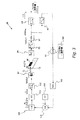
図1を参照して、記憶テープ駆動装置における記憶テープの横方向テープ移動(LTM)を検出するためのテープ縁部センサシステムが与えられる。システム10は記憶テープ12のそのような横方向移動を検出するために用いられる。記憶テープ12は、第1のテープ縁部14、第2のテープ縁部16、第1のテープ側18および第2のテープ側20を含む。動作中、テープ12は、方向d2に沿って生じる横方向テープ移動を伴って方向d1に沿って移動する。典型的には、横方向テープ移動は0〜約10kHzの周波数を有する。システム10は、光信号S1を発する第1のフォトエミッタ22、第1の光信号S1の一部を受取るよう位置決めされる第1の光検出器24を含む。第1のフォトエミッタ22は、第1の光信号が変調もされるように、変調される。第1の光検出器24は、第1の光検出器24によって受取られた第1の光信号の一部に比例する第1の検出信号を出力する。ある改良では、第1のフォトエミッタ22はレーザダイオードであり、および/または第1の光検出器24はフォトダイオード(透過的に光学的に結合された装置)である。第1のバッフル30は、第1のフォトエミッタ22と第1の光検出器24との間に配置される第1の開口32を含む。第1の開口32は、第1のテープ縁部14に、第1の光信号S1の一部がそこを通って第1の光検出器24によって受取られる第1の領域34を規定する。第1のテープ縁部14は第1の光信号を部分的に遮断し(つまり、バッフル30は第1の光検出器24および第1のテープ縁部14の光路に配置され)、それによって、第1の開口32とともに、第1の光検出器24によって受取られる第1の信号の一部における変動が横方向テープ移動によって少なくとも一部生じるように、第1の光検出器24によって受取られる第1の光信号の一部を規定する。
Referring to FIG. 1, a tape edge sensor system is provided for detecting lateral tape movement (LTM) of a storage tape in a storage tape drive.
システム10は、さらに、第1のフォトエミッタ22および第1の光検出器24に接続される帰還システム40を含む。テープ12の輪郭は信号を生成し、それは、捕捉され、テープ移動として登録される。少なくとも2つの種類のテープ移動があることが十分に理解されるべきである。一方の移動は、テープ12が方向d2に沿って上下に移動する定常波移動である。他方の移動は、テープ12がねじれ曲がる進行波移動である。わずか1つのフォトエミッタ/光検出器構成しか用いられない場合、これらの2つの種類の移動間を区別することは困難である。この問題に対応する変形例が以下に述べられる。
The
ある改良では、帰還システム40は第1のフォトエミッタ22および第1の光検出器24に接続する。帰還システム40は、さらに、第1のフォトエミッタ22の振幅変調および第1の検出された信号のローパスフィルタ処理を与えて、ノイズおよび信号ドリフトからの干渉を最小限にする。ある改良では、帰還システム40は第1の検出信号を受取り、第1の光信号を調整して、第1の検出信号の振幅が第1の平均振幅範囲内にあるようにする。帰還システム40は、さらに、予め定められる値からの第1のテープ縁部の偏差を表す第1の出力信号を出力する。帰還システム40の変形例の詳細は以下により詳細に述べられる。
In one refinement, the
図2Aおよび図2Bは異なる開口の向きの概略図を与える。開口32はこの発明の変形例において光学フィルタとして動作する。開口32は2つの空間的寸法l1およびl2によって特徴付けられる。図2Aでは、l1はl2より大きく、l1はテープ移動の方向d1に実質的に平行に整列している。この構成は、LTM測定中の縁部テープ損傷および/または縁部粗さに対して多少影響を受けにくい。図2Bでは、l2はl1より大きく、l1はテープ移動の方向d1に実質的に平行に整列している。この構成はLTM測定中の縁部テープ損傷および/または縁部粗さに対して敏感であり、したがって、そのような損傷の評価ための技術を与える。
2A and 2B give schematic views of different aperture orientations. The
この実施の形態の変形例では、システム10は、さらに、第2のフォトエミッタ42、第2のフォトエミッタ42から第2の光信号S2の一部を受取るよう位置決めされる第2の光検出器44を含む。ある改良では、第2のフォトエミッタ42はレーザダイオードであり、および/または第2の光検出器44はフォトダイオードである。第2のフォトエミッタ42は、第2の光信号が変調もされるように、変調される。第2の光検出器44は、第2の光検出器44によって受取られた第2の光信号の一部に比例する第2の検出された信号を出力する。第2のバッフル46は第2の開口48を含み、第2のフォトエミッタ42と第2の光検出器44との間に配置される。第2の開口48は、第2のテープ縁部16に第2の領域50を規定し、第2の光信号は、記憶テープ12が第2の光信号の一部を遮断する状態で、第2の領域50を介して第2の光検出器44によって受取られる。この変形例では、頂部および底部移動は調整され、それによって、テープ12の移動(たとえば、変動するかもしれないテープ縁部損傷またはテープ幅)変化についてのよりよい情報を与える。ある改良では、帰還システム40は第2のフォトエミッタ42および第2の光検出器44に接続する。帰還システム40は、さらに、第1のフォトエミッタ42の振幅変調および第2の検出された信号のローパスフィルタ処理を与えて、ノイズおよび信号ドリフトからの干渉を最小限にする。帰還システム40は第2の検出された信号振幅を受取り、第2の光信号を調整して、第2の検出された信号振幅が第2の平均振幅範囲内にあるようにする。帰還システム40は、さらに、予め定められる値からの第2のテープ縁部の偏差を表す第2の出力信号を出力する。
In a variation of this embodiment, the
さらに、この実施の形態のさらなる変形例では、システム10は、上に述べられるような2つのさらなるフォトエミッタ/ダイオード対をさらに含む。具体的には、システム10は、さらに、第3のフォトエミッタ52、および第3のフォトエミッタ52から第3の光信号を受取るよう位置決めされる第3の光検出器54を含む。ある改良では、第3のフォトエミッタ52はレーザダイオードであり、第3の光検出器54はフォトダイオードである。第3のフォトエミッタ52は、第3の光信号が変調もされるように、変調される。第3の光検出器54は、第3の光検出器54によって受取られた第3の光信号の一部に比例する第3の検出信号を出力する。第3のバッフル56は第3の開口58を含み、第3のフォトエミッタ52と第3の光検出器54との間に配置される。第3の開口58は、第1
のテープ縁部14に第3の領域60を規定し、第3の光信号は、記憶テープ12が第3の光信号の一部を遮断する状態で、第3の領域60を介して第3の光検出器54によって受取られる。この変形例では、システム10は、さらに、第4のフォトエミッタ62、および第4のフォトエミッタ62から第4の光信号を受取るよう位置決めされる第4の光検出器64を含む。第4のフォトエミッタ62は、第4の光信号が変調もされるように、変調される。第4の光検出器64は、第4の光検出器64によって受取られた第4の光信号の一部に比例する第4の検出信号を出力する。ある改良では、第4のフォトエミッタ62はレーザダイオードであり、および/または第4の光検出器64はフォトダイオードである。第4のバッフル66は第4の開口68を含み、第4のフォトエミッタ62と第4の光検出器64との間に配置される。第4の開口68は、第2のテープ縁部16に第4の領域70を規定し、第4の光信号は、記憶テープ12が第4の光信号の一部を遮断する状態で、第4の領域70を介して第4の光検出器64によって受取られる。ある改良では、安定部72を光検出器の対間に配置して、テープ12の移動を安定させる。そのような改良では、テープヘッドは安定部72の反対側に位置決めされる。第3のフォトエミッタ52および第3の光検出器54も、上に述べられるように帰還システム40に接続される。
Further, in a further variation of this embodiment, the
A
ある改良では、帰還システム40は第3のフォトエミッタ52および第3の光検出器54に接続する。帰還システム40は、さらに、第3のフォトエミッタ52の振幅変調および第3の検出された信号のローパスフィルタ処理を与えて、ノイズおよび信号ドリフトからの干渉を最小限にする。あるさらなる改良では、帰還システム40は第3の検出された信号を受取り、第3の光信号を調整して、第3の検出信号の振幅が第3の平均振幅範囲内にあるようにする。帰還システム40は、さらに、予め定められる値からの第1のテープ縁部の偏差を表す第3の出力信号を出力する。同様に、第4のフォトエミッタ62および第4の光検出器64も、上に述べられるように帰還システム40に接続され、帰還システム40も、第4のフォトエミッタ62の振幅変調および第4の検出された信号のローパスフィルタ処理を与えて、ノイズおよび信号ドリフトからの干渉を最小限にする。さらに、あるさらなる改良では、帰還システム40は第4の検出された信号振幅を受取り、第4の光信号を調整して、第4の検出信号の振幅が第4の平均振幅範囲内にあるようにする。帰還システム40は、さらに、予め定められる値からの第2のテープ縁部の偏差を表す第4の出力信号を出力する。
In one refinement, the
上に述べられるように、テープ移動は定常波および進行波移動の両方によって特徴付けられてもよい。4つのフォトエミッタ/光検出器対の利用は、1つまたは2つのフォトエミッタ/光検出器対よりも、これらの2つの移動間のよりよい差分を与える。たとえば、テープ移動を示す信号が、まず光検出器24および44で観察され、次いである時間間隔後に光検出器54および64で観察される場合、テープ移動は進行波のそれである、と結論付けられてもよい。対照的に、連続信号は、テープ移動が光検出器24、44、54および64で同時に受取られることを示す。これらの測定は、ある程度まで、テープ縁部損傷から独立している。
As noted above, tape movement may be characterized by both standing wave and traveling wave movement. The use of four photoemitter / photodetector pairs gives a better difference between these two movements than one or two photoemitter / photodetector pairs. For example, if a signal indicative of tape movement is first observed with
この変形例では、4つの光検出器が関連付けられる開口とともにテープ安定部の側部に配置される。4つの光検出器の利用は、以下のように、光検出器24および44の対が安定部72に対して前方位置68に位置し、光検出器54および64の対が安定部72に対して後方位置70に位置する状態で、LTM測定の精度を改善する。LTMの計算は以下の等式を介して達成される:
A=LTMa+Na
B=LTMb+Nb
C=LTMc+Nc
D=LTMd+Nd
式中、A、B、C、Dは、それぞれ光検出器24、44、54および64からの信号であり、Na、Nb、NcおよびNdは各検出器と関連付けられる非コヒーレントノイズであり;LTMa、LTMb、LTMcおよびLTMaは、それぞれ光検出器24、44、54および64によって検出される横方向テープ移動であり;LTMfは前方位置68での横方向テープ移動であり;LTMbは後方位置70における横方向テープ移動である。LTMa=LTMb=LTMfおよびLTMC=LTMd=LTMbであるので、A+B=2LTMf+Na+NbはLTMf=(A+B)/2+(Na+Nb)/2を意味する。NaおよびNbは非コヒーレントノイズであるので、(Na+Nb)/2<NaまたはNbおよびC+D=2LTMb+Nc+Nd=>LTMb=(C+D)/2+(Nc+Nd)2である。NcおよびNdは非コヒーレントノイズであるので、(Nc+Nd)/2<NcまたはNdである。したがって、LTMfおよびLTMbは、位置68および70における、より正確な測定値である。さらにテープ送りシステムまたは安定部それ自体のためにテープ上に瞬間の傾きがある場合、LTMf(t)≠LTMb(t)であり、したがって傾き=LTMf(t)−LTMb(t)である。
In this variant, four photodetectors are arranged on the side of the tape stabilizer with an associated opening. The use of four photodetectors is as follows: the pair of
A = LTM a + N a
B = LTM b + N b
C = LTM c + N c
D = LTM d + N d
Where A, B, C, D are signals from
図1A、図1B、図2Aおよび図2Bを参照して、開口のさまざまな向きが与えられる。図2Aは、その長軸がテープ縁部14に平行な状態で開口32が配置される改良を与える。この構成は、光路上における開口の暗に含まれる境界のため縁部変位または移動に対する光検出器24の感度の増大を可能にする(つまり、検出器によって検出される最大のおよび最小の光は、テープの縁部の近くの領域において幾何学的に集中される)。この種の開口の適用は、縁部切断または縁部損傷の汚染影響を抑えるという利点も有する。任意の瞬間でのテープ縁部の開口視野の慎重な検査で、テープの瞬間の定常波移動(実際のLTM)は、テープ縁部を越えて通過する発光の変化のため、検出器によって精密に検出されるが、開口の長さ未満の波長を有するテープ縁部の進行波移動は平均され、したがって、光学的にフィルタ処理されることが明らかになる。この現象は非常に望ましく、なぜならば、テープ縁部形状輪郭(損傷した縁部が含まれる)は進行波タイプのものであり、それはこの光学的設定においてはフィルタ処理され、抑制されるからである。
With reference to FIGS. 1A, 1B, 2A and 2B, various orientations of the openings are provided. FIG. 2A provides an improvement in which the
この実施の形態の変形例では、フォトエミッタから発せられる光信号は変調される。たとえば、レーザダイオードを介する印加される電流は、結果として、光検出器24によって検出される光強度の変調になる。バンドパスフィルタ処理および他の信号処理が用いられる。たとえば、検出器のコレクタ/エミッタ電流は光変調されたダイオードの搬送周波数でフィルタ処理される(つまり、検出器により検知された信号を復調する)。ダイオードの変調に対する検出器の感度は、外部の光学的および電気的ノイズによって引起されるコンタミネーションの低減によって感度を増大させる。典型的には、この搬送周波数は、LTMに対する典型的な周波数(0〜10kHz)よりはるかに高い(約100kHz以上)。この原理は、図2において示されるようなLTM検出器設定において利用することが可能である。先に記載された透過型光学対および開口の設定、ならびにここで説明されるようなレーザ発振する光のさらなる変調および次いでの復調によって登録されるLTMの精度は、かなり改善する。LTMは、ここに記載される光学的移動検出器設定に関して変動がないので、測定されたLTMの平均値は、成分ドリフトまたは他の低い周波数の電気機械的および環境的外乱がないとして、一定に留まるはずである。
In a variation of this embodiment, the optical signal emitted from the photoemitter is modulated. For example, the current applied through the laser diode results in a modulation of the light intensity detected by the
図3を参照して、上に述べられた横方向テープ移動検出システムにおいて用いられる帰還システムの概略的な例示が与えられる。帰還システムは、振幅変調(AM)を用いて、LTM検出中におけるノイズおよびドリフトの影響を最小限にする。LTM検出システム80は、フォトエミッタ82、光検出器84、および開口88を規定するバッフル86を含む。フォトエミッタ82、光検出器84、バッフル86および開口88は、上に述べられるように構成される。フォトエミッタ82は、振幅変調された信号S3を発し、それは光検出器84に伝搬される。テープ12の上側端縁は光信号を部分的に遮断し、信号S’3が光検出器84によって受取られる。光検出器84の出力は、周波数fc−光信号が振幅変調される近似周波数−を中心とするバンドパスフィルタ90によってフィルタ処理される。次いで、バンドパスフィルタ90の出力は全波整流器92を通して渡され、全波整流器92は、負の値が正の値に変換されるAC信号を与える。全波整流器92の出力はローパスフィルタ94および96に与えられる。両方のローパスフィルタ94および96の遮断周波数faはfcより低い。パスフィルタ94はLTMを示す出力信号を与え、一方ローパスフィルタ96の出力は加算回路98に与えられる。設定点で電圧が加算回路98に与えられ、ローパスフィルタ96の出力と比較される。設定点電圧とローパスフィルタ96からの信号との間の差が判断され、次いで、加算回路104に与えられる。周波数変換器106が、AC信号を加算回路104に与える。したがって、加算回路104は方形波生成器108にAC信号を出力し、方形波生成器108は周波数fcの方形波を出力する。方形波は積算器110に与えられ、それによって、周波数fcの三角波を出力する。方形波生成器108によって出力される周波数は、横方向テープ移動の典型的な周波数(0〜10kHz)よりはるかに大きな値(100kHz以上)に設定される。三角波は、バンドパスフィルタ112を通過し、正弦波に変換され、それはフォトエミッタ82を駆動するのに使用される。この改良の帰還ループは、典型的には、テープが開口88の面積のおおよそ半分を遮断することに対応するようにLTM電圧を設定する。これは検出器のスケーリングの正規化ならびに温度ドリフトおよび外部の光学的および電気的ノイズによる測定変動の抑制を斟酌する。図3に呈示される自動利得制御(AGC)ループは、モデル化光の振幅をダイオードレベルで調整して、任意の成分ドリフトおよび他の超低周波外乱の抑制を保証する。
With reference to FIG. 3, a schematic illustration of a feedback system used in the lateral tape movement detection system described above is given. The feedback system uses amplitude modulation (AM) to minimize the effects of noise and drift during LTM detection. The
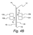
別の実施の形態では、記憶テープ駆動装置におけるテープばたつきの影響を最小限にするためのテープ縁部センサシステムが提供される。図4Aおよび図4Bは、記憶テープ駆動装置における記憶テープの「ばたつき」移動を補償するシステムに対する概略的な図解を提供する。ばたつき移動は、「z軸」−テープ表面およびテープ移動方向d1に垂直な方向−に沿った移動によって特徴付けられる。テープ縁部検知のための先行技術の方法は、平行にされた(平行)光を用いず、および/または一致しない光放射パターンと検出器感度パターンとを有する。これはセンサの伝達関数を図5に述べられるようにテープばたつきと共に変動させる。この実施の形態では、このテープばたつきは、テープ縁部上に近接して配置されるが、向きが反転された2つのフォトインタラプタを用いることによって、補償される。 In another embodiment, a tape edge sensor system is provided for minimizing the effects of tape flapping in a storage tape drive. 4A and 4B provide a schematic illustration for a system that compensates for “flapping” movement of a storage tape in a storage tape drive. The flapping movement is characterized by movement along the “z-axis” —the direction perpendicular to the tape surface and the tape movement direction d 1 . Prior art methods for tape edge detection do not use collimated (parallel) light and / or have light emission patterns and detector sensitivity patterns that do not match. This causes the transfer function of the sensor to vary with tape flutter as described in FIG. In this embodiment, this tape flutter is compensated by using two photointerrupters that are placed close to each other on the tape edge but are inverted in orientation.
さらに図4Aおよび図4Bを参照して、記憶テープ駆動装置における記憶テープの「ばたつき」移動を補償するシステムが提供される。記憶テープ12は、第1のテープ縁部14、第2のテープ縁部16、第1のテープ側18および第2のテープ側20を含む。システム120は、第1の非平行光信号S5を発する第1のフォトエミッタ122、および第1の光検出器124を含む。第1のフォトエミッタ122は第1のテープ側18に近接して位置決めされ、一方、第1の光検出器124は第2のテープ側20に近接して、第1の非平行光信号S5の一部を受取るよう位置決めされる。第1の非平行光信号S5は、記憶テープ12によって第1のテープ縁部14で部分的に遮断される。システム120は、さらに、第2の非平行光信号S6を発する第2のフォトエミッタ128、および第2の光検出器130を含む。第2のフォトエミッタ128は第2のテープ側20に近接して位置決めされ、一方、第2の光検出器130は第1のテープ側18に近接して位置決めされる。第2の光検出器130は、第2の非平行光信号S6の一部を受取る。第2の非平行光信号S6は、記憶テープによって第1のテープ縁部14で部分的に遮断される。記憶テープの反対側における第1のフォトエミッタ122および第2のフォトエミッタ128、ならびに記憶テープの反対側における第1の光検出器124および第2の光検出器130の位置決めは、第1のテープ側および第2のテープ側に垂直な方向(つまりZ方向)における記憶テープの移動を少なくとも部分的に補償する。結果として生じる信号がZ依存を有さないように、第1の光検出器124および第2の光検出器130からの信号は構成要素12
6によって電子的に結合(加算)される。テープのZ位置が変動するにつれて、一方のフォトインタラプタの伝達関数の傾きにおける変化は、第2のフォトインタラプタの傾きにおける変化と同じ大きさを有するが、反対の符号を有し、それらの信号が加算されると、2つのセンサの反対の傾きは相殺する。ある改良では、第1のフォトエミッタ128および第1の光検出器124はフォトインタラプタ132内に含まれ、一方、第2のフォトエミッタ122および第2の光検出器130はフォトインタラプタ134内に含まれる。この解決策の有効性は、2つのフォトインタラプタが一致するZ依存性を有すること、それらの伝達関数が適切な相殺を得るために整列するように、それらは鉛直に整列されること、およびテープが2つのセンサ間の距離(約3mmまたは4mm)を横断する際にテープのZ移動は著しく変化しないことを必要とする。
Still referring to FIGS. 4A and 4B, a system for compensating for “flapping” movement of a storage tape in a storage tape drive is provided. The
6 is electronically coupled (added). As the Z position of the tape fluctuates, the change in the slope of the transfer function of one photointerrupter has the same magnitude as the change in the slope of the second photointerrupter, but has the opposite sign, When added, the opposite slopes of the two sensors cancel. In one refinement, the
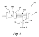
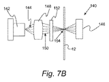
図6、図7A、図7B、図8Aおよび図8Bを参照して、記憶テープ駆動装置における記憶テープの横方向テープ移動(LTM)を検出するためのさらなるシステムが提供される。この実施の形態は、レーザからの平行にされた(平行)光を用いて、Z依存性問題に対するさらなる解決策を提供する。図6は、単一のテープ縁部を監視してLTMを判断する、記憶テープ駆動装置における横方向テープ移動を検出するためのシステムの概略図を与える。システム140は、典型的にはレーザダイオードであるフォトエミッタ142を含み、それは、光束144を発し、それはテープ12の第1のテープ縁部14によって部分的に遮断され、光検出器146(例えばPINフォトダイオード)によって受取られる。システム140は、さらに、光束144を平行にして平行光束150を形成するレンズ148を含む。平行光束150はテープ12の表面に垂直に整列させられ、光検出器146のテープと対向する側に落ち、フォトインタラプタからの伝達関数と同様の伝達関数が生成される。しかしながら、この場合では、信号はテープのZ位置に依存しない。図7Aおよび図7Bは、レンズを用いて、テープ縁部上に入射する光信号を成形する、図6の改良物の概略的な図である。図7Aは側面図であり、図7Bは上面図である。この改良では、円柱レンズ152を用いて、テープ12上のテープ縁部14での光信号の光学的な足跡154を調整する。円柱レンズ152を光路に追加することにより、上に述べられるようにテープの面において1つの方向においてのみ照射パターンを低減または拡大できる。レーザ光線は横方向(LTM、または上記の図では鉛直)において平行性を維持するので、センサの伝達関数のZ依存はさらに最小限にされる。図8Aおよび図8Bは、達成可能な照射パターンの図を提供する。図8Aでは、照射パターン154は長軸がテープ縁部に平行な楕円形である。図2Aとの関連で上に述べられるように、この構成は、LTM測定中において縁部テープ損傷に対して多少影響を受けにくい。図8Bでは、照射パターンは同様に楕円形であるが、長軸がテープ縁部に垂直である。図2Bとの関連で上に述べられるように、この構成は、LTM測定中において縁部テープ損傷に対して敏感であり、したがって、そのような損傷の評価ための技術を提供する。
With reference to FIGS. 6, 7A, 7B, 8A, and 8B, a further system for detecting lateral tape movement (LTM) of a storage tape in a storage tape drive is provided. This embodiment uses a collimated (parallel) light from the laser to provide a further solution to the Z dependency problem. FIG. 6 provides a schematic diagram of a system for detecting lateral tape movement in a storage tape drive that monitors a single tape edge to determine the LTM. The
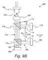
図9Aは、頂部テープ縁部および底部テープ縁部を監視して、平行光光源を用いながらLTMを判断する、記憶テープ駆動装置における横方向テープ移動を検出するためのシステムの概略図を与える。システム160は、典型的にはレーザダイオードであるフォトエミッタ162を含む。フォトエミッタ162は光信号164を発し、それは、光信号164を平行にして平行光信号168を形成するよう用いられるレンズ166によって平行にされる。第1の光学装置170は、平行光信号168の第1の部分172を光検出器174に向かって反射する。テープ縁部14は、第1の部分172の一部を遮断し、それによって、LTMの評価を可能にする。第1の光学装置170は、さらに、第2の部分176を第2の光学装置178に向かって透過する。ある改良では、第1の光学装置170はビームスプリッタである。第2の光学装置178は、平行光信号168の第3の部分180を光検出器182に向かって反射する。テープ縁部16は、第3の部分180の一部を遮断し、それによって、LTMの評価を可能にする。ある改良では、第2の光学装置178はミラーまたはビームスプリッタのいずれかである。この変形例は、テープ12のZ位置から独立したLTMの検出を可能にする。図9Bは、図9Aのシステムの改良物を提供する。この改良では、システム160’は、平行光信号168の第3の部分180を光検出器182に向かって反射し、第4の部分188を光検出器190に向かって透過する、第2の光学装置178’を含む。光検出器190からの出力信号は、光信号168の光強度の変動が補償されるように、システム160の正規化を可能にする。この実施の形態のレーザ縁部センサは、実験室試験取付具またはテープ駆動装置製品のいずれにおいても、テープ経路のまわりで狭い空間内に取付けることに対して有用な非常に小さな設置面積で設計することが可能である。
FIG. 9A provides a schematic diagram of a system for detecting lateral tape movement in a storage tape drive that monitors the top and bottom tape edges to determine the LTM while using a parallel light source.
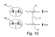
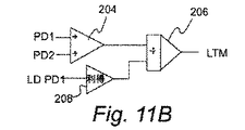
図10および図11A〜図11Cを参照して、フォトダイオード由来の信号においてノイズを低減する変形例が提供される。そのようなノイズはLTM測定においては誤差に変換する。この種のセンサにおいて可能な限りノイズを低減するために、レーザ光線における相対強度ノイズは、信号を正規化することによって、測定誤差に寄与するものとして低減される。これは、縁部移動またはLTMを示す信号を、レーザ光線における全体出力を表す信号によって除算することによって行うことが可能である。図10を参照して、レーザダイオード装置192および194は光信号を発し、それは、それぞれ光検出器PD1およびPD2によって受取られる。光信号は、上に述べられるように記憶テープ12の頂縁部14および底縁部16によって部分的に遮られる。全体の光線出力を表す信号を、LDPD1およびLDPD2として識別されるレーザダイオード装置の背面検出器から導き出すことが可能である。検出器LDPD1およびLDPD2は、レーザダイオード装置192のレーザダイオードPD1およびレーザダイオード装置194のレーザダイオードPD2由来の光の一部を受取る。図11A、図11Bおよび図11Cは、LDPD1およびLDPD2の出力を用いるためのさまざまな構成を提供する。図11Aを参照して、頂縁部信号および底縁部信号の測定のための構成が提供される。この構成では、PD1の出力および増幅された出力LDPD1は分圧器198に与えられる。LDPD1の増幅は増幅器200を介して達成される。同様に、PD2の出力および増幅された出力LDPD2は分圧器202に与えられる。LDPD2の増幅は増幅器204を介して達成される。図11Bを参照して、LTMを直接測定するための構成が提供される。この構成では、PD1およびPD2の出力は電圧加算器204に与えられる。電圧加算器204の出力および増幅された出力LDPD1は、分圧器206に与えられる。LDPD1の増幅は増幅器208を介して達成される。図を11C参照して、テープ幅に対する構成が与えられる。この構成では、PD1およびPD2の出力は差動増幅器210に与えられる。差動増幅器210の出力および増幅された出力LDPD1は、分圧器212に与えられる。LDPD1の増幅は増幅器214を介して達成される。図11A〜図11Cと関連付けられる方法は、信号正規化が、信号のデジタル化後にアナログ電子回路またはデジタル信号プロセッサを用いて達成される状態で、レーザ出力変動が最終測定において補償されることを可能にする。
With reference to FIG. 10 and FIGS. 11A to 11C, a modification for reducing noise in a signal derived from a photodiode is provided. Such noise is converted into an error in the LTM measurement. In order to reduce the noise as much as possible in this type of sensor, the relative intensity noise in the laser beam is reduced as contributing to measurement errors by normalizing the signal. This can be done by dividing the signal indicating edge movement or LTM by the signal representing the total power in the laser beam. Referring to FIG. 10 ,
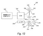
図12を参照して、テープ縁部センサを較正するためのシステムが提供される。高レベルの測定精度を達成するために、テープ縁部センサは精密な較正を必要とする。センサの伝達関数の最も重要な部分は、その中間点−線形測定領域−近くである。縁部センサの出力信号と同時にテープ移動を精密に測定する較正方法は、所望の情報:測定領域における伝達関数の傾きを与える。較正システム220は平面の較正基板222(たとえば小さいテープ材料のサンプル)、および平面の較正基板を線形方向d7に移動する線形平行移動装置224を含む。典型的には、線形平行移動装置224は、小さいテープ材料のサンプルを移動させるために低周波数(≒10Hz)発振器226からの正弦波信号によって駆動されるボイスコイルモータである。光源230および光検出器232はテープ縁部センサ228の一部である。光源230は光信号を発し、それは、一部が平面基板222によって遮断される状態で、光検出器232によって受取られる。平面の較正基板222は、テープ縁部センサ228の伝達関数の中央領域が線形平行移動装置224によって掃引されるように、テープ縁部センサ228に位置決めされる。平面の較正基板222と一致して移動する可動反射器234が、線形平行移動装置224に取付けられる。システム220は、さらに、単色光信号238を発するレーザ236を含む。キューブビームスプリッタ240は、光信号の第1の部分242を可動反射器234に向かって反射し、光信号の第2の部分244を定置反射器246に向かって透過する。定置反射器246は、光信号の第3の部分248をビームスプリッタ240に向けて戻し、そこで、光の第4の部分250が光検出器252に向けられる。ある改良では、可動反射器234および定置反射器の両方はコーナーキューブ反射器である。可動反射器234は、光信号の第5の部分254をビームスプリッタ240に向けて戻し、そこで、光信号の第6の部分256が光検出器252(例えばフォトダイオード)に透過される。光信号の第4の部分250および光信号の第6の部分256は、構築的および破壊的に結合して、干渉計信号(例えば干渉パターン)を平面の較正基板222の位置の関数として形成する。干渉パターンは、平面の較正基板によって横断される距離の判断を可能にする周期を有する。光検出器252からの結果として生じる干渉計信号は、レーザの波長の1/2(λ/2)と等しい線形平行移動装置224の移動をその周期が表す正弦波である。650nm(赤色)のレーザダイオードに対しては、この周期は325nmを表す。図13は、縁部センサの伝達関数のグラフ上に重ねられた較正システムの出力の例を与える。線形領域における傾きは、伝達関数と交差するサイクル数を計数することによって、点P1とP2との間の距離から評価される。伝達関数の傾き(ボルト/ナノメートル)は、この較正方法によって生成される信号から計算される。高い絶対確度を達成するために、レーザの波長は、たとえばそれを光学分光計で測定することによって、正確に知られていなければならない。
Referring to FIG. 12, a system for calibrating a tape edge sensor is provided. To achieve a high level of measurement accuracy, the tape edge sensor requires precise calibration. The most important part of the sensor transfer function is its midpoint-the linear measurement region-near. A calibration method that precisely measures tape movement simultaneously with the edge sensor output signal gives the desired information: the slope of the transfer function in the measurement area.
この発明の実施の形態が示され記載されたが、これらの実施の形態がこの発明のすべての可能な形式を示し記載することは意図されない。むしろ、明細書において用いられる文言は限定ではなく記述の文言であり、さまざまな変更がこの発明の精神および範囲から逸脱せずに行なわれてもよいことが理解される。 While embodiments of the invention have been shown and described, it is not intended that these embodiments show and describe all possible forms of the invention. Rather, it is understood that the language used in the specification is a descriptive language rather than a limitation, and that various changes may be made without departing from the spirit and scope of the invention.
Claims (10)
第1の光信号を発する第1のフォトエミッタを含み、前記第1のフォトエミッタは、前記第1の光信号が変調もされるように、変調され、前記テープ縁部センサシステムは、
前記第1の光信号の一部を受取るよう位置決めされ、受取った前記第1の光信号の前記一部に比例する第1の検出された信号を与える第1の光検出器と、
第1の開口を規定する第1のバッフルとをさらに含み、前記第1のバッフルは前記第1のフォトエミッタと前記第1の光検出器との間に配置され、前記第1の開口は、前記第1のテープ縁部に、横方向テープ移動が検出される第1の領域を規定し、前記第1のテープ縁部は前記第1の光信号を部分的に遮断し、それによって、前記第1の開口とともに、前記第1の光検出器によって受取られる前記第1の光信号の前記一部における変動が横方向テープ移動によって少なくとも一部生じるように、前記第1の光検出器によって受取られる前記第1の光信号の前記一部を規定し、前記テープ縁部センサシステムはさらに、
第3の光信号を発する第3のフォトエミッタを含み、前記第3のフォトエミッタは、前記第3の光信号が変調もされるように、変調され、前記テープ縁部センサシステムは、
前記第3の光信号の一部を受取るよう位置決めされ、受取った前記第3の光信号の前記一部に比例する第3の検出された信号を与える第3の光検出器と、
第3の開口を規定する第3のバッフルとをさらに含み、前記第3のバッフルは前記第3のフォトエミッタと前記第3の光検出器との間に配置され、前記第3の開口は、前記第1のテープ縁部に、横方向テープ移動が検出される第3の領域を規定し、前記第1のテープ縁部は前記第3の光信号を部分的に遮断し、それによって、前記第3の開口とともに、前記第3の光検出器によって受取られる前記第3の光信号の前記一部における変動が横方向テープ移動によって少なくとも一部生じるように、前記第3の光検出器によって受取られる前記第3の光信号の前記一部を規定し、前記テープ縁部センサシステムはさらに、
前記第1および第3のフォトエミッタと、前記第1および第3の光検出器とに接続される帰還システムを含み、前記帰還システムは、前記第1ならびに第3のフォトエミッタの変調および前記第1ならびに第3の検出された信号のローパスフィルタ処理を与えて、ノイズおよび信号ドリフトからの干渉を最小限にし、前記テープ縁部センサシステムは、
前記記憶テープの横方向移動を安定させる安定部をさらに含み、
前記第1の光検出器は前記安定部に対して前方位置に位置し、前記第3の光検出器は前記安定部に対して後方位置に位置する、テープ縁部センサシステム。 A tape edge sensor system for detecting lateral movement of a storage tape in a storage tape drive, the storage tape comprising: a first tape edge; a second tape edge; a first tape side; Having a second tape side, a lateral tape movement is a movement of the storage tape in a direction perpendicular to the storage tape movement during a read / write operation, the tape edge sensor system comprising:
A first photoemitter that emits a first optical signal, wherein the first photoemitter is modulated such that the first optical signal is also modulated, and the tape edge sensor system comprises:
A first photodetector positioned to receive a portion of the first optical signal and providing a first detected signal proportional to the portion of the received first optical signal;
Further comprising a first baffle defining a first opening, the first baffle is disposed between said first photodetector and said first photo-emitter, said first opening, The first tape edge defines a first region in which lateral tape movement is detected, the first tape edge partially blocking the first optical signal, thereby Received by the first photodetector so that a variation in the portion of the first optical signal received by the first photodetector along with the first aperture is caused at least in part by lateral tape movement. Defining the portion of the first optical signal to be produced , the tape edge sensor system further comprising:
A third photoemitter that emits a third optical signal, wherein the third photoemitter is modulated such that the third optical signal is also modulated, and the tape edge sensor system comprises:
A third photodetector positioned to receive a portion of the third optical signal and providing a third detected signal proportional to the portion of the received third optical signal;
A third baffle defining a third aperture, wherein the third baffle is disposed between the third photoemitter and the third photodetector, the third aperture comprising: The first tape edge defines a third region in which lateral tape movement is detected, the first tape edge partially blocking the third optical signal, thereby Received by the third photodetector so that a variation in the portion of the third optical signal received by the third photodetector along with a third aperture is at least partially caused by lateral tape movement. Defining the portion of the third optical signal to be produced, the tape edge sensor system further comprising:
Said first and third photo-emitter, wherein said first and third feedback system connected to the photodetector, the feedback system, modulation and said first and third photo-emitter second Providing a low pass filtering of the first and third detected signals to minimize interference from noise and signal drift , the tape edge sensor system comprising:
And further comprising a stabilizing part for stabilizing the lateral movement of the storage tape,
The tape edge sensor system , wherein the first photodetector is located at a front position with respect to the stable portion, and the third photodetector is located at a rear position with respect to the stable portion .
前記第2のフォトエミッタから前記第2の光信号の一部を受取るよう位置決めされ、受取った前記第2の光信号の前記一部に比例する第2の検出された信号を与える第2の光検出器と、
第2の開口を規定する第2のバッフルとを含み、前記第2のバッフルは前記第2のフォトエミッタと前記第2の光検出器との間に配置され、前記第2の開口は、前記第2のテープ縁部に、横方向テープ移動が検出される第2の領域を規定し、前記第2のテープ縁部は前記第2の光信号を部分的に遮断し、それによって、前記第2の開口とともに、前記第2の光検出器によって受取られる前記第2の光信号の前記一部における変動が横方向テープ移動によって少なくとも一部生じるように、前記第2の光検出器によって受取られる前記第2の光信号の前記一部を規定し、前記帰還システムは前記第2のフォトエミッタおよび前記第2の光検出器に接続し、前記帰還システムは、前記第2の光検出器の変調および前記第2の検出された信号のローパスフィルタ処理を与えて、ノイズおよび信号ドリフトからの干渉を最小限にする、請求項1に記載のテープ縁部センサシステム。 A second photoemitter that emits a second optical signal, wherein the second photoemitter is modulated such that the second optical signal is also modulated, and the tape edge sensor system further comprises:
Second light positioned to receive a portion of the second optical signal from the second photoemitter and providing a second detected signal proportional to the portion of the received second optical signal. A detector;
A second baffle defining a second opening, wherein the second baffle is disposed between the second photoemitter and the second photodetector, and the second opening comprises the second baffle A second tape edge defines a second region in which lateral tape movement is detected, the second tape edge partially blocking the second optical signal, thereby With two apertures, received by the second photodetector such that variations in the portion of the second optical signal received by the second photodetector are caused at least in part by lateral tape movement. Defining the portion of the second optical signal, the feedback system connected to the second photoemitter and the second photodetector, the feedback system modulating the second photodetector; And the second detected signal low Giving pass filter process, to minimize interference from noise and signal drift, the tape edge sensor system according to claim 1.
前記第4のフォトエミッタから前記第4の光信号の一部を受取るよう位置決めされ、受取った前記第4の光信号の前記一部に比例する第4の検出された信号を与える第4の光検出器と、
第4の開口を規定する第4のバッフルとを含み、前記第4のバッフルは前記第4のフォトエミッタと前記第4の光検出器との間に配置され、前記第4の開口は、前記第2のテープ縁部に、横方向テープ移動が検出される第4の領域を規定し、前記第2のテープ縁部は前記第4の光信号を部分的に遮断し、それによって、前記第4の開口とともに、前記第4の光検出器によって受取られる前記第4の光信号の前記一部における変動が横方向テープ移動によって少なくとも一部生じるように、前記第4の光検出器によって受取られる前記第4の光信号の前記一部を規定し、前記帰還システムは、前記第4のフォトエミッタおよび前記第4の光検出器に接続し、前記帰還システムは、前記第4の光検出器の変調および前記第4の検出された信号のローパスフィルタ処理を与えて、ノイズおよび信号ドリフトからの干渉を最小限にする、請求項2に記載のテープ縁部センサシステム。 And a fourth photoemitter that emits a fourth optical signal, wherein the fourth photoemitter is modulated such that the fourth optical signal is also modulated, and the tape edge sensor system further comprises:
A fourth light positioned to receive a portion of the fourth optical signal from the fourth photoemitter and providing a fourth detected signal proportional to the portion of the received fourth optical signal; A detector;
A fourth baffle defining a fourth aperture, wherein the fourth baffle is disposed between the fourth photoemitter and the fourth photodetector, and the fourth aperture is A second tape edge defines a fourth region in which lateral tape movement is detected, and the second tape edge partially blocks the fourth optical signal, thereby With four apertures, received by the fourth photodetector such that variations in the portion of the fourth optical signal received by the fourth photodetector are caused at least in part by lateral tape movement. defining the portion of the fourth optical signal, the feedback system, before SL connected to the fourth photo emitter and the fourth light detector, the feedback system, before Symbol fourth photodetecting Hollow varying Totonoo and the fourth detected signal of the vessel Giving pass filtering process, to minimize interference from noise and signal drift, the tape edge sensor system of claim 2.
Applications Claiming Priority (3)
| Application Number | Priority Date | Filing Date | Title |
|---|---|---|---|
| US13/531,875 US8760786B2 (en) | 2012-06-25 | 2012-06-25 | Lateral tape motion detector |
| US13/531,875 | 2012-06-25 | ||
| PCT/US2013/045629 WO2014004096A1 (en) | 2012-06-25 | 2013-06-13 | Lateral tape motion detector |
Publications (3)
| Publication Number | Publication Date |
|---|---|
| JP2015526707A JP2015526707A (en) | 2015-09-10 |
| JP2015526707A5 JP2015526707A5 (en) | 2016-04-07 |
| JP6190880B2 true JP6190880B2 (en) | 2017-08-30 |
Family
ID=48699971
Family Applications (1)
| Application Number | Title | Priority Date | Filing Date |
|---|---|---|---|
| JP2015518458A Active JP6190880B2 (en) | 2012-06-25 | 2013-06-13 | Horizontal tape movement detector |
Country Status (8)
| Country | Link |
|---|---|
| US (1) | US8760786B2 (en) |
| EP (1) | EP2864984B1 (en) |
| JP (1) | JP6190880B2 (en) |
| CN (1) | CN104272385B (en) |
| AU (1) | AU2013280927B2 (en) |
| HK (1) | HK1204137A1 (en) |
| NZ (1) | NZ629024A (en) |
| WO (1) | WO2014004096A1 (en) |
Families Citing this family (6)
| Publication number | Priority date | Publication date | Assignee | Title |
|---|---|---|---|---|
| US10365217B2 (en) * | 2013-11-12 | 2019-07-30 | Illinois Tool Works Inc. | Liquid presence/turbidity sensor using single optical channel |
| US9123377B1 (en) | 2014-10-03 | 2015-09-01 | Oracle International Corporation | Apparatus and method for allowing passage of a leader through a tape drive tape path |
| KR101766777B1 (en) * | 2016-01-27 | 2017-08-09 | 한국산업기술대학교 산학협력단 | Apparatus for detecting the direction of movement |
| CN110686603B (en) * | 2019-09-27 | 2021-06-22 | 中科精瓒(武汉)医疗技术有限公司 | Belt drive positioning calibration method and device |
| CN112431009A (en) * | 2020-11-22 | 2021-03-02 | 苏州比达尔创新材料科技有限公司 | Textile fabric levelness perching and checking equipment |
| CN115183758B (en) * | 2022-09-07 | 2022-12-06 | 四川图林科技有限责任公司 | Electromagnetic jitter detection device and detection method for ultrahigh-precision laser gyroscope |
Family Cites Families (17)
| Publication number | Priority date | Publication date | Assignee | Title |
|---|---|---|---|---|
| NL7712418A (en) | 1977-11-11 | 1979-05-15 | Philips Nv | RECORDING AND / OR DISPLAY DEVICE FOR A BAND-SHAPED MAGNETIC RECORDING CARRIER EQUIPPED WITH A MAGNETIC HEAD POSITIONING CONTROL SYSTEM. |
| US4913328A (en) | 1987-06-05 | 1990-04-03 | Odetics, Inc. | Active tape tracking system with crown guide rollers for magnetic recorder/players |
| US5362973A (en) | 1990-06-25 | 1994-11-08 | Xerox Corporation | Quantum fabricated via photo induced evaporation enhancement during in situ epitaxial growth |
| US5172186A (en) * | 1990-07-03 | 1992-12-15 | Konica Corporation | Laser interferometry length measuring an apparatus employing a beam slitter |
| EP0471101B1 (en) | 1990-08-14 | 1997-03-12 | Tandberg Data A/S | Method for positioning a magnetic head on a magnetic memory surface |
| EP0531947B1 (en) * | 1991-09-09 | 1997-01-02 | Kabushiki Kaisha Tokai Rika Denki Seisakusho | Position detecting apparatus |
| JP3080476B2 (en) * | 1992-05-29 | 2000-08-28 | 株式会社東海理化電機製作所 | Position detection device |
| US5412474A (en) | 1992-05-08 | 1995-05-02 | Smithsonian Institution | System for measuring distance between two points using a variable frequency coherent source |
| FR2712691B1 (en) | 1993-11-19 | 1995-12-22 | Bernard Fondeur | Laser interferometry measurement device. |
| JP3974670B2 (en) * | 1996-05-28 | 2007-09-12 | 松下電工株式会社 | Optical displacement measuring device |
| US5991112A (en) * | 1997-03-04 | 1999-11-23 | Excel Precision | Non-contact servotrack writing with phase sensitive detection |
| JP2001208533A (en) * | 2000-01-25 | 2001-08-03 | Sony Corp | Measuring method of degree of width-wise serpentine of long-sized body and apparatus therefor and production method of magnetic record medium and apparatus therefor |
| US6580581B1 (en) * | 2000-08-16 | 2003-06-17 | International Business Machines Corporation | Recovery of lateral position of a servo system with respect to longitudinal servo bands of a magnetic tape |
| US6697206B2 (en) | 2000-12-19 | 2004-02-24 | Imation Corp. | Tape edge monitoring |
| US7136255B2 (en) | 2003-10-20 | 2006-11-14 | Quantum Corporation | Servo methods and systems using masked medium edge position sensors |
| US20060103968A1 (en) * | 2004-11-12 | 2006-05-18 | Jurneke Joe K | Dynamic skew compensation systems and associated methods |
| US8643975B2 (en) * | 2009-12-21 | 2014-02-04 | International Business Machines Corporation | Method and apparatus for operating a storage device |
-
2012
- 2012-06-25 US US13/531,875 patent/US8760786B2/en active Active
-
2013
- 2013-06-13 CN CN201380019029.8A patent/CN104272385B/en active Active
- 2013-06-13 AU AU2013280927A patent/AU2013280927B2/en active Active
- 2013-06-13 NZ NZ629024A patent/NZ629024A/en unknown
- 2013-06-13 EP EP13732035.4A patent/EP2864984B1/en active Active
- 2013-06-13 WO PCT/US2013/045629 patent/WO2014004096A1/en unknown
- 2013-06-13 JP JP2015518458A patent/JP6190880B2/en active Active
-
2015
- 2015-05-15 HK HK15104638.3A patent/HK1204137A1/en unknown
Also Published As
| Publication number | Publication date |
|---|---|
| CN104272385A (en) | 2015-01-07 |
| EP2864984A1 (en) | 2015-04-29 |
| US20130342930A1 (en) | 2013-12-26 |
| AU2013280927B2 (en) | 2019-01-03 |
| JP2015526707A (en) | 2015-09-10 |
| HK1204137A1 (en) | 2015-11-06 |
| AU2013280927A1 (en) | 2014-09-11 |
| EP2864984B1 (en) | 2018-10-03 |
| CN104272385B (en) | 2017-03-01 |
| WO2014004096A1 (en) | 2014-01-03 |
| US8760786B2 (en) | 2014-06-24 |
| NZ629024A (en) | 2016-07-29 |
Similar Documents
| Publication | Publication Date | Title |
|---|---|---|
| JP6190880B2 (en) | Horizontal tape movement detector | |
| US20020075588A1 (en) | Tape edge monitoring | |
| JP4093971B2 (en) | Optical movement information detection apparatus, movement information detection system, electronic apparatus and encoder | |
| JP2020513557A (en) | Optical particle sensor module | |
| JP2019522778A (en) | Particle sensor, particle detection method, and computer program | |
| US6713743B2 (en) | Fabry-perot resonator and system for measuring and calibrating displacement of a cantilever tip using the same in atomic force microscope | |
| BR112019011460A2 (en) | laser sensor module, mobile communication device, particle detection method and computer program product | |
| US7449678B2 (en) | Optical encoder having reference position detection | |
| JP2015526707A5 (en) | ||
| EP3415861A1 (en) | Contact making feeler head for coordinate measuring machine using a photoluminescent material and quadrant photodetectors for monitoring the feeler displacement | |
| JPS6231282B2 (en) | ||
| JPWO2014132379A1 (en) | Fourier transform infrared spectrophotometer | |
| KR20190128068A (en) | Laser sensor module for particle detection with offset beam | |
| US5315373A (en) | Method of measuring a minute displacement | |
| KR101093080B1 (en) | Surface plasmon bio-sensor using feedback optical source | |
| JP4576014B2 (en) | Optical encoder | |
| JP2626009B2 (en) | Particle size distribution analyzer | |
| JP4093942B2 (en) | Speedometer, displacement meter, vibrometer and electronic equipment | |
| JP4595697B2 (en) | Reflective optical gap sensor | |
| JPH09281252A (en) | Optical type continuous and automatic by-blown-snow/ sand-size measuring instrument | |
| JPS5856094B2 (en) | Microvibration measuring device | |
| CN107783379B (en) | Compensation method for measurement information | |
| JPH02193041A (en) | Particle size distribution apparatus | |
| JPH074909A (en) | Laser sensor apparatus | |
| JPH06307848A (en) | Probe displacement sensing device of microscope |
Legal Events
| Date | Code | Title | Description |
|---|---|---|---|
| A521 | Request for written amendment filed |
Free format text: JAPANESE INTERMEDIATE CODE: A523 Effective date: 20160215 |
|
| A621 | Written request for application examination |
Free format text: JAPANESE INTERMEDIATE CODE: A621 Effective date: 20160215 |
|
| A131 | Notification of reasons for refusal |
Free format text: JAPANESE INTERMEDIATE CODE: A131 Effective date: 20161213 |
|
| A977 | Report on retrieval |
Free format text: JAPANESE INTERMEDIATE CODE: A971007 Effective date: 20161214 |
|
| A521 | Request for written amendment filed |
Free format text: JAPANESE INTERMEDIATE CODE: A523 Effective date: 20170215 |
|
| TRDD | Decision of grant or rejection written | ||
| A01 | Written decision to grant a patent or to grant a registration (utility model) |
Free format text: JAPANESE INTERMEDIATE CODE: A01 Effective date: 20170718 |
|
| A61 | First payment of annual fees (during grant procedure) |
Free format text: JAPANESE INTERMEDIATE CODE: A61 Effective date: 20170807 |
|
| R150 | Certificate of patent or registration of utility model |
Ref document number: 6190880 Country of ref document: JP Free format text: JAPANESE INTERMEDIATE CODE: R150 |
|
| R250 | Receipt of annual fees |
Free format text: JAPANESE INTERMEDIATE CODE: R250 |
|
| R250 | Receipt of annual fees |
Free format text: JAPANESE INTERMEDIATE CODE: R250 |
|
| R250 | Receipt of annual fees |
Free format text: JAPANESE INTERMEDIATE CODE: R250 |
|
| R250 | Receipt of annual fees |
Free format text: JAPANESE INTERMEDIATE CODE: R250 |