JP6190865B2 - Manufacturing method and apparatus for manufacturing electrolyte membrane / electrode structure with resin frame - Google Patents
Manufacturing method and apparatus for manufacturing electrolyte membrane / electrode structure with resin frame Download PDFInfo
- Publication number
- JP6190865B2 JP6190865B2 JP2015240874A JP2015240874A JP6190865B2 JP 6190865 B2 JP6190865 B2 JP 6190865B2 JP 2015240874 A JP2015240874 A JP 2015240874A JP 2015240874 A JP2015240874 A JP 2015240874A JP 6190865 B2 JP6190865 B2 JP 6190865B2
- Authority
- JP
- Japan
- Prior art keywords
- electrolyte membrane
- adhesive layer
- electrode
- mea
- resin frame
- Prior art date
- Legal status (The legal status is an assumption and is not a legal conclusion. Google has not performed a legal analysis and makes no representation as to the accuracy of the status listed.)
- Active
Links
Images


Classifications
-
- H—ELECTRICITY
- H01—ELECTRIC ELEMENTS
- H01M—PROCESSES OR MEANS, e.g. BATTERIES, FOR THE DIRECT CONVERSION OF CHEMICAL ENERGY INTO ELECTRICAL ENERGY
- H01M8/00—Fuel cells; Manufacture thereof
- H01M8/02—Details
- H01M8/0271—Sealing or supporting means around electrodes, matrices or membranes
- H01M8/0273—Sealing or supporting means around electrodes, matrices or membranes with sealing or supporting means in the form of a frame
-
- H—ELECTRICITY
- H01—ELECTRIC ELEMENTS
- H01M—PROCESSES OR MEANS, e.g. BATTERIES, FOR THE DIRECT CONVERSION OF CHEMICAL ENERGY INTO ELECTRICAL ENERGY
- H01M8/00—Fuel cells; Manufacture thereof
- H01M8/10—Fuel cells with solid electrolytes
- H01M8/1004—Fuel cells with solid electrolytes characterised by membrane-electrode assemblies [MEA]
-
- Y—GENERAL TAGGING OF NEW TECHNOLOGICAL DEVELOPMENTS; GENERAL TAGGING OF CROSS-SECTIONAL TECHNOLOGIES SPANNING OVER SEVERAL SECTIONS OF THE IPC; TECHNICAL SUBJECTS COVERED BY FORMER USPC CROSS-REFERENCE ART COLLECTIONS [XRACs] AND DIGESTS
- Y02—TECHNOLOGIES OR APPLICATIONS FOR MITIGATION OR ADAPTATION AGAINST CLIMATE CHANGE
- Y02E—REDUCTION OF GREENHOUSE GAS [GHG] EMISSIONS, RELATED TO ENERGY GENERATION, TRANSMISSION OR DISTRIBUTION
- Y02E60/00—Enabling technologies; Technologies with a potential or indirect contribution to GHG emissions mitigation
- Y02E60/30—Hydrogen technology
- Y02E60/50—Fuel cells
-
- Y—GENERAL TAGGING OF NEW TECHNOLOGICAL DEVELOPMENTS; GENERAL TAGGING OF CROSS-SECTIONAL TECHNOLOGIES SPANNING OVER SEVERAL SECTIONS OF THE IPC; TECHNICAL SUBJECTS COVERED BY FORMER USPC CROSS-REFERENCE ART COLLECTIONS [XRACs] AND DIGESTS
- Y02—TECHNOLOGIES OR APPLICATIONS FOR MITIGATION OR ADAPTATION AGAINST CLIMATE CHANGE
- Y02P—CLIMATE CHANGE MITIGATION TECHNOLOGIES IN THE PRODUCTION OR PROCESSING OF GOODS
- Y02P70/00—Climate change mitigation technologies in the production process for final industrial or consumer products
- Y02P70/50—Manufacturing or production processes characterised by the final manufactured product
Description
本発明は、固体高分子電解質膜を第1電極及び第2電極で挟んだ段差MEAと、前記段差MEAの外周に接合される樹脂枠部材とを備える燃料電池用の樹脂枠付き電解質膜・電極構造体の製造方法及びその製造装置に関する。 The present invention relates to an electrolyte membrane / electrode with a resin frame for a fuel cell, comprising: a step MEA having a solid polymer electrolyte membrane sandwiched between a first electrode and a second electrode; and a resin frame member joined to the outer periphery of the step MEA. The present invention relates to a structure manufacturing method and a manufacturing apparatus thereof.
一般的に、固体高分子型燃料電池は、高分子イオン交換膜からなる固体高分子電解質膜を採用している。燃料電池は、固体高分子電解質膜の一方の面にアノード電極が、前記固体高分子電解質膜の他方の面にカソード電極が、それぞれ配設された電解質膜・電極構造体(MEA)を備えている。アノード電極及びカソード電極は、それぞれ触媒層(電極触媒層)とガス拡散層(多孔質カーボン)とを有している。 In general, a polymer electrolyte fuel cell employs a polymer electrolyte membrane made of a polymer ion exchange membrane. The fuel cell includes an electrolyte membrane / electrode structure (MEA) in which an anode electrode is disposed on one surface of a solid polymer electrolyte membrane and a cathode electrode is disposed on the other surface of the solid polymer electrolyte membrane. Yes. The anode electrode and the cathode electrode each have a catalyst layer (electrode catalyst layer) and a gas diffusion layer (porous carbon).
電解質膜・電極構造体は、セパレータ(バイポーラ板)によって挟持されることにより、発電セル(単位燃料電池)が構成されている。この発電セルは、所定の数だけ積層することにより、例えば、車載用燃料電池スタックとして使用されている。 The electrolyte membrane / electrode structure is sandwiched between separators (bipolar plates) to form a power generation cell (unit fuel cell). This power generation cell is used as, for example, an in-vehicle fuel cell stack by stacking a predetermined number.
電解質膜・電極構造体では、一方のガス拡散層が固体高分子電解質膜よりも小さな平面寸法に設定されるとともに、他方のガス拡散層が前記固体高分子電解質膜と略同一の平面寸法に設定される、所謂、段差MEAを構成する場合がある。その際、比較的高価な固体高分子電解質膜の使用量を削減させるとともに、薄膜状で強度が低い前記固体高分子電解質膜を保護するために、樹脂枠部材を組み込んだ樹脂枠付きMEAが採用されている。 In the electrolyte membrane / electrode structure, one gas diffusion layer is set to a plane size smaller than that of the solid polymer electrolyte membrane, and the other gas diffusion layer is set to substantially the same plane size as the solid polymer electrolyte membrane. The so-called step MEA may be configured. At that time, in order to reduce the amount of the relatively expensive solid polymer electrolyte membrane used and to protect the solid polymer electrolyte membrane having a thin film shape and low strength, an MEA with a resin frame incorporating a resin frame member is adopted. Has been.
樹脂枠付きMEAを製造する方法として、例えば、特許文献1に開示されている燃料電池用樹脂枠付き電解質膜・電極構造体の製造方法が知られている。この製造方法では、樹脂製枠部材の内周突部と固体高分子電解質膜の外周縁部とが、接着層、例えば、エステル系、アクリル系又はウレタン系のホットメルト接着剤により固定されている。
As a method for producing an MEA with a resin frame, for example, a method for producing an electrolyte membrane / electrode structure with a resin frame for a fuel cell disclosed in
通常、MEAの製造作業には、例えば、特許文献2に開示されているように、吸着用治具が用いられている。この特許文献2では、吸着用治具を構成する多孔部材の吸着面上に基材が保持されるとともに、前記基材に触媒インクが塗布される工程を有している。従って、樹脂枠付きMEAの製造方法では、電解質膜・電極構造体が吸着用治具に吸着保持された状態で、前記電解質膜・電極構造体上に接着層が設けられている。
In general, for example, as disclosed in
ところで、接着層の厚さが厚くなると、発電セル自体の厚さが大きくなるとともに、接着代が必要になり、前記発電セルの発電面積を効率的に確保することが困難になる。このため、接着層の厚さを可及的に薄く形成することが望まれている。 By the way, when the thickness of the adhesive layer is increased, the thickness of the power generation cell itself is increased, and an adhesive margin is required, which makes it difficult to efficiently secure the power generation area of the power generation cell. For this reason, it is desired to form the adhesive layer as thin as possible.
しかしながら、接着層は、比較的大きな寸法を有する枠形状を有するため、薄肉化されると、剛性が著しく悪化して取り扱い性が低下するという問題がある。しかも、接着層を精度良く配設することができず、MEAと樹脂枠部材との貼り合わせ精度が低下するおそれがある。 However, since the adhesive layer has a frame shape having a relatively large size, there is a problem that when the thickness is reduced, the rigidity is remarkably deteriorated and the handleability is lowered. In addition, the adhesive layer cannot be disposed with high accuracy, and the bonding accuracy between the MEA and the resin frame member may be reduced.
本発明は、この種の問題を解決するものであり、簡単な工程で、薄肉な枠状接着層を段差MEAの所望の部位に高精度且つ確実に貼り付けることができ、前記段差MEAと樹脂枠部材とを精度良く接合することが可能な樹脂枠付き電解質膜・電極構造体の製造方法及びその製造装置を提供することを目的とする。 The present invention solves this type of problem, and with a simple process, a thin frame-like adhesive layer can be adhered to a desired portion of the step MEA with high accuracy and reliability. It is an object of the present invention to provide a manufacturing method and an apparatus for manufacturing an electrolyte membrane / electrode structure with a resin frame capable of accurately joining a frame member.
本発明は、段差MEAと樹脂枠部材とを有する燃料電池用の樹脂枠付き電解質膜・電極構造体の製造方法及びその製造装置に関するものである。段差MEAでは、固体高分子電解質膜の一方の面には、第1電極が設けられ、前記固体高分子電解質膜の他方の面には、第2電極が設けられ、前記第1電極の平面寸法は、前記第2電極の平面寸法よりも大きな寸法に設定されている。樹脂枠部材は、固体高分子電解質膜の、第2電極の外方に露呈する外周面に、枠状の接着層により接合されている。 The present invention relates to a manufacturing method and an apparatus for manufacturing an electrolyte membrane / electrode structure with a resin frame for a fuel cell having a step MEA and a resin frame member. In the step MEA, a first electrode is provided on one surface of the solid polymer electrolyte membrane, a second electrode is provided on the other surface of the solid polymer electrolyte membrane, and the planar dimension of the first electrode is Is set to a dimension larger than the planar dimension of the second electrode. The resin frame member is joined to the outer peripheral surface of the solid polymer electrolyte membrane exposed to the outside of the second electrode by a frame-shaped adhesive layer.
この製造方法では、作業テーブル上で、第1吸引機構を介して段差MEAが吸引保持された状態で、接着層が設けられたフィルム部材は、第2吸引機構を介して該接着層が該段差MEAに重なり合うように吸引保持されている。そして、接着層が段差MEAに貼り付けられた後、フィルム部材が剥離され、前記接着層を介して前記段差MEAと樹脂枠部材とが接合されている。 In this manufacturing method, a film member provided with an adhesive layer in a state in which the step MEA is sucked and held via the first suction mechanism on the work table, the adhesive layer is provided with the step via the second suction mechanism. It is sucked and held so as to overlap the MEA. And after an adhesive layer is affixed on level | step difference MEA, a film member is peeled and the said level | step difference MEA and the resin frame member are joined via the said adhesive layer.
また、この製造方法では、接着層が設けられたフィルム部材をロール状に巻回したフィルムロールが用意され、前記フィルムロールが巻き戻されて作業テーブルに繰り出されることが好ましい。次いで、作業テーブルは、テーブル面に垂直な軸回りに回転することにより、接着層の貼り付け位置に対応して段差MEAを位置決めすることが好ましい。 Moreover, in this manufacturing method, it is preferable that a film roll obtained by winding a film member provided with an adhesive layer into a roll is prepared, and the film roll is rewound and fed out to a work table. Next, the work table is preferably rotated around an axis perpendicular to the table surface, thereby positioning the step MEA corresponding to the attachment position of the adhesive layer.
さらに、この製造方法では、接着層を段差MEAに貼り付ける前に、該接着層と該段差MEAとを部分的に接合させる仮止め処理を行うことが好ましい。 Furthermore, in this manufacturing method, it is preferable to perform a temporary fixing process in which the adhesive layer and the step MEA are partially joined before the adhesive layer is attached to the step MEA.
さらにまた、この製造方法では、接着層が設けられたフィルム部材をロール状に巻回したフィルムロールが用意され、前記フィルムロールが巻き戻されて繰り出されることが好ましい。次に、段差MEA上の接着層始端位置、接着層終端位置及び接着層長さが計測され、接着層は、前記計測された情報に基づいて切断され、作業テーブル上に移送されることが好ましい。 Furthermore, in this manufacturing method, it is preferable that a film roll obtained by winding a film member provided with an adhesive layer into a roll is prepared, and the film roll is rewound and fed out. Next, the adhesive layer start position, adhesive layer end position and adhesive layer length on the step MEA are measured, and the adhesive layer is preferably cut based on the measured information and transferred onto the work table. .
また、この製造装置では、作業テーブル上に段差MEAを吸引保持する第1吸引機構と、前記第1吸引機構により該段差MEAが吸引保持された状態で、接着層が設けられたフィルム部材を、該接着層が該段差MEAに重なり合うように吸引保持する第2吸引機構と、を備えている。 Further, in this manufacturing apparatus, a first suction mechanism that sucks and holds the step MEA on the work table, and a film member provided with an adhesive layer in a state where the step MEA is sucked and held by the first suction mechanism, A second suction mechanism for sucking and holding the adhesive layer so as to overlap the stepped MEA.
本発明によれば、作業テーブル上で、第1吸引機構を介して、例えば、イオン交換膜の微少リーク特性を利用しつつ、段差MEAが吸引保持されるとともに、第2吸引機構を介して接着層が設けられたフィルム部材が前記段差MEA上に吸引保持されている。従って、特に、薄肉化された接着層であっても、フィルム部材に設けられているため、剛性を確保することができ、取り扱い性が良好に向上する。 According to the present invention, the step MEA is sucked and held on the work table through the first suction mechanism, for example, while utilizing the minute leak characteristic of the ion exchange membrane, and bonded through the second suction mechanism. A film member provided with a layer is sucked and held on the step MEA. Therefore, in particular, even a thinned adhesive layer is provided on the film member, so that rigidity can be ensured and handling properties are improved satisfactorily.
しかも、接着層は、フィルム部材を介して段差MEA上に吸引保持されている。これにより、簡単な工程で、薄肉な接着層を段差MEAの所望の部位に高精度且つ確実に貼り付けることができ、前記段差MEAと樹脂枠部材とを精度良く接合することが可能になる。 Moreover, the adhesive layer is sucked and held on the step MEA via the film member. Thereby, it is possible to attach a thin adhesive layer to a desired portion of the step MEA with high accuracy and reliability by a simple process, and it is possible to join the step MEA and the resin frame member with high accuracy.
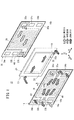
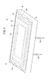
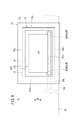
図1及び図2に示すように、本発明に係る製造方法が適用される樹脂枠付き電解質膜・電極構造体10は、横長(又は縦長)の長方形状の固体高分子型発電セル(単位セル)12に組み込まれる。複数の発電セル12は、例えば、矢印A方向(水平方向)又は矢印C方向(重力方向)に積層されて燃料電池スタックが構成される。燃料電池スタックは、例えば、車載用燃料電池スタックとして燃料電池電気自動車(図示せず)に搭載される。
As shown in FIGS. 1 and 2, an electrolyte membrane /
発電セル12は、樹脂枠付き電解質膜・電極構造体10を第1セパレータ14及び第2セパレータ16で挟持する。第1セパレータ14及び第2セパレータ16は、横長(又は縦長)の長方形状を有する。第1セパレータ14及び第2セパレータ16は、例えば、鋼板、ステンレス鋼板、アルミニウム板、めっき処理鋼板、あるいはその金属表面に防食用の表面処理を施した金属板や、カーボン部材等で構成される。
The
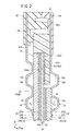
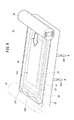
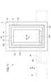
長方形状の樹脂枠付き電解質膜・電極構造体10は、段差MEA10aを備える。図2に示すように、段差MEA10aは、例えば、パーフルオロスルホン酸の薄膜に水が含浸された固体高分子電解質膜18と、前記固体高分子電解質膜18を挟持するアノード電極(第1電極)20及びカソード電極(第2電極)22とを有する。固体高分子電解質膜18は、陽イオン交換膜であり、フッ素系電解質の他、HC(炭化水素)系電解質を使用してもよい。
The electrolyte membrane /
カソード電極22は、固体高分子電解質膜18及びアノード電極20よりも小さな平面寸法(外形寸法)を有するとともに、前記固体高分子電解質膜18と前記アノード電極20とは、同一の平面寸法を有する。なお、上記の構成に代えて、アノード電極20は、固体高分子電解質膜18及びカソード電極22よりも小さな平面寸法を有するように構成してもよい。その際、アノード電極20は、第2電極となり、カソード電極22は、第1電極となる。
The
図2に示すように、アノード電極20は、固体高分子電解質膜18の一方の面18aに接合される第1電極触媒層20aと、前記第1電極触媒層20aに積層される第1ガス拡散層20bとを設ける。第1電極触媒層20a及び第1ガス拡散層20bは、同一の平面寸法(外形寸法)を有するとともに、固体高分子電解質膜18と同一(又は同一未満)の平面寸法に設定される。なお、第1電極触媒層20aは、第1ガス拡散層20bよりも小さな平面寸法(又は大きな平面寸法)に設定されてもよい。
As shown in FIG. 2, the
カソード電極22は、固体高分子電解質膜18の面18bに接合される第2電極触媒層22aと、前記第2電極触媒層22aに積層される第2ガス拡散層22bとを設ける。第2電極触媒層22a及び第2ガス拡散層22bは、同一の平面寸法を有するとともに、固体高分子電解質膜18の平面寸法よりも小さな平面寸法に設定される。固体高分子電解質膜18の面18b側の外周縁部には、カソード電極22の外方に露呈する露出面18beが設けられる。
The
なお、第2電極触媒層22aと第2ガス拡散層22bとは、同一の平面寸法に設定されているが、前記第2電極触媒層22aの平面寸法は、前記第2ガス拡散層22bの平面寸法よりも大きな寸法(又は小さな寸法)を有してもよい。
The second
第1電極触媒層20aは、例えば、白金合金が表面に担持された多孔質カーボン粒子が、第1ガス拡散層20bの表面に一様に塗布されて形成される。第2電極触媒層22aは、例えば、白金合金が表面に担持された多孔質カーボン粒子が、第2ガス拡散層22bの表面に一様に塗布されて形成される。
The first
第1ガス拡散層20bは、多孔性と導電性を有するマイクロポーラス層20b(m)と、カーボンペーパ又はカーボンクロス等のカーボン層20b(c)とから形成される。第2ガス拡散層22bは、多孔性と導電性を有するマイクロポーラス層22b(m)と、カーボンペーパ又はカーボンクロス等のカーボン層22b(c)とから形成される。第2ガス拡散層22bの平面寸法は、第1ガス拡散層20bの平面寸法よりも小さく設定される。
The first
第1電極触媒層20aと第2電極触媒層22aとは、固体高分子電解質膜18の面18aと面18bとに形成される。なお、マイクロポーラス層20b(m)及び22b(m)は、必要に応じて設ければよく、不要にすることもできる。
The first
樹脂枠付き電解質膜・電極構造体10は、固体高分子電解質膜18の露出面18beに接合されるフィルム状の樹脂枠部材(断面が異形状の樹脂成形体又は厚さが一定の樹脂フィルム)24を備える。
The resin membrane-attached electrolyte membrane /
樹脂枠部材24は、例えば、PPS(ポリフェニレンサルファイド)、PPA(ポリフタルアミド)、PEN(ポリエチレンナフタレート)、PES(ポリエーテルサルフォン)、LCP(リキッドクリスタルポリマー)、PVDF(ポリフッ化ビニリデン)、シリコーン樹脂、フッ素樹脂、m−PPE(変性ポリフェニレンエーテル樹脂)、PET(ポリエチレンテレフタレート)、PBT(ポリブチレンテレフタレート)又は変性ポリオレフィン等で構成される。
The
樹脂枠部材24は、薄肉状の内側突出部24aを有し、前記内側突出部24aには、固体高分子電解質膜18の露出面18beに接合される接着面24asが設けられる。固体高分子電解質膜18の露出面18beと樹脂枠部材24の接着面24asとの間には、例えば、ホットメルトシート等の接着フィルム26aによる枠状接着層26が設けられる。
The
図1に示すように、発電セル12の矢印B方向(図1中、水平方向)の一端縁部には、積層方向である矢印A方向に互いに連通して、酸化剤ガス入口連通孔30a、冷却媒体入口連通孔32a及び燃料ガス出口連通孔34bが設けられる。酸化剤ガス入口連通孔30aは、酸化剤ガス、例えば、酸素含有ガスを供給する一方、冷却媒体入口連通孔32aは、冷却媒体を供給する。燃料ガス出口連通孔34bは、燃料ガス、例えば、水素含有ガスを排出する。酸化剤ガス入口連通孔30a、冷却媒体入口連通孔32a及び燃料ガス出口連通孔34bは、矢印C方向(鉛直方向)に配列して設けられる。
As shown in FIG. 1, one end edge portion of the
発電セル12の矢印B方向の他端縁部には、矢印A方向に互いに連通して、燃料ガスを供給する燃料ガス入口連通孔34a、冷却媒体を排出する冷却媒体出口連通孔32b、及び酸化剤ガスを排出する酸化剤ガス出口連通孔30bが設けられる。燃料ガス入口連通孔34a、冷却媒体出口連通孔32b及び酸化剤ガス出口連通孔30bは、矢印C方向に配列して設けられる。
The other end edge of the
樹脂枠部材24には、酸化剤ガス入口連通孔30a、冷却媒体入口連通孔32a、燃料ガス出口連通孔34b、燃料ガス入口連通孔34a、冷却媒体出口連通孔32b及び酸化剤ガス出口連通孔30bは形成されない。すなわち、樹脂枠部材24の外周端は、6つの連通孔の内方に位置する。
The
第1セパレータ14の樹脂枠付き電解質膜・電極構造体10に向かう面14aには、燃料ガス入口連通孔34aと燃料ガス出口連通孔34bとに連通して矢印B方向に延在する複数本の燃料ガス流路36が形成される。燃料ガス流路36は、複数本の波状流路溝又は直線状流路溝を有する。
The
第2セパレータ16の樹脂枠付き電解質膜・電極構造体10に向かう面16aには、酸化剤ガス入口連通孔30aと酸化剤ガス出口連通孔30bとに連通して矢印B方向に延在する酸化剤ガス流路38が設けられる。酸化剤ガス流路38は、複数本の波状流路溝又は直線状流路溝を有する。
The
互いに隣接する第1セパレータ14の面14bと第2セパレータ16の面16bとの間には、冷却媒体入口連通孔32aと冷却媒体出口連通孔32bとに連通して矢印B方向に延在する複数本の流路溝を有する冷却媒体流路40が形成される。
Between the
図1及び図2に示すように、第1セパレータ14の面14a、14bには、この第1セパレータ14の外周端部を周回して、第1シール部材42が一体化される。第2セパレータ16の面16a、16bには、この第2セパレータ16の外周端部を周回して、第2シール部材44が一体化される。
As shown in FIGS. 1 and 2, the
図2に示すように、第1シール部材42は、樹脂枠付き電解質膜・電極構造体10を構成する樹脂枠部材24に当接する第1凸状シール42aと、第2セパレータ16の第2シール部材44に当接する第2凸状シール42bとを有する。第2シール部材44は、第2凸状シール42bに当接する面がセパレータ面に沿って平面状に延在する平面シールを構成する。なお、第2凸状シール42bに代えて、第2シール部材44に凸状シール(図示せず)を設けてもよい。
As shown in FIG. 2, the
第1シール部材42及び第2シール部材44には、例えば、EPDM、NBR、フッ素ゴム、シリコーンゴム、フロロシリコーンゴム、ブチルゴム、天然ゴム、スチレンゴム、クロロプレーン又はアクリルゴム等のシール材、クッション材、あるいはパッキン材等の弾性を有するシール部材が用いられる。
For the
次いで、樹脂枠付き電解質膜・電極構造体10を製造するための本発明の第1の実施形態に係る製造方法について、以下に説明する。
Next, a manufacturing method according to the first embodiment of the present invention for manufacturing an electrolyte membrane /
先ず、段差MEA10aが作製される一方、樹脂枠部材24は、金型(図示せず)を用いて射出成形された部材、又は、フィルムをトムソン刃で枠状に切断した部材が用意される。
First, while the
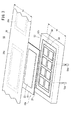
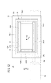
図3に示すように、樹脂枠付き電解質膜・電極構造体10を製造する製造装置50は、作業テーブル52を備える。作業テーブル52の上面(載置面)52sには、内側吸着ライン(第1吸引機構)54と外側吸着ライン(第2吸引機構)56とが設けられる。
As shown in FIG. 3, the
内側吸着ライン54は、例えば、格子状の溝により形成され、段差MEA10aを構成するアノード電極20の平面寸法内に設けられる。外側吸着ライン56は、例えば、内側吸着ライン54を周回する長方形状の溝により形成されるとともに、段差MEA10aの平面寸法よりも大きな寸法に形成される。
The
内側吸着ライン54には、作業テーブル52の内部を貫通した複数の小孔を介して第1吸引管54aが接続され、図示しない吸引源に連通する。外側吸着ライン56には、作業テーブル52の内部を貫通した複数の小孔を介して第2吸引管56aが接続され、図示しない吸引源に連通する。第1吸引管54aと第2吸引管56aとは、独立して吸引される。なお、内側吸着ライン54及び外側吸着ライン56は、それぞれ複数個の細孔により形成してもよい。
A
そこで、段差MEA10aが作業テーブル52上に吸引される。具体的には、段差MEA10aは、アノード電極20を下向きにして作業テーブル52の上面52sに載置される。作業テーブル52では、第1吸引管54aの吸引作用下に、内側吸着ライン54が吸引され、段差MEA10aは、イオン交換膜の微少リーク特性を利用しつつ、上面52sに吸引保持される。
Therefore, the
一方、フィルム部材(キャリアフィルム)58が用意される。フィルム部材58は、例えば、PET(ポリエチレンテレフタレート)等で形成される長尺ウエブである。フィルム部材58には、矩形の枠状の接着フィルム26aが所定間隔ずつ離間して複数個設けられる。接着フィルム26aは、数μm〜250μmの厚さに設定される。
On the other hand, a film member (carrier film) 58 is prepared. The
なお、フィルム部材58は、単一の接着フィルム26aを設ける矩形状(作業テーブル52と同等の寸法)に設定されてもよい。フィルム部材58の幅寸法S1は、作業テーブル52の幅寸法S2と同等、僅かに大きな寸法又は僅かに小さな寸法に設定される。
The
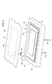
次いで、図4に示すように、作業テーブル52上にフィルム部材58が配置され、撮像器60a、60bにより、段差MEA10aと接着フィルム26aとの相対的な位置が検出される。そして、段差MEA10aと接着フィルム26aとの位置決めが行われた後、図5に示すように、フィルム部材58が作業テーブル52上の前記段差MEA10aに重ねられ、第2吸引管56aが吸引される。このため、外側吸着ライン56が吸引され、フィルム部材58は、接着フィルム26aが段差MEA10aに重なり合うように吸引保持されている。
Next, as shown in FIG. 4, the
段差MEA10aが、作業テーブル52の上面52sに吸引保持されるとともに、フィルム部材58が前記段差MEA10aに重なって吸引保持された状態で、図6に示すように、ヒータローラ62による加圧及び加熱処理が施される。ヒータローラ62は、フィルム部材58上を回転しながら移動することにより、接着フィルム26aが段差MEA10aに貼り付けられる。なお、加圧加熱方式としては、ヒータローラ62の他、接着形状に応じた熱盤等を使用することができる。また、接着フィルム26aが自己タック性を有する際には、加圧のみで加熱する必要はない。
While the
段差MEA10aに接着フィルム26aが貼り付けられた後、必要に応じて冷却処理が行われる。さらに、第2吸引管56aによる吸引が解除されるとともに、フィルム部材58が作業テーブル52から剥離される。その後、段差MEA10aと接着フィルム26aとの貼り付け状態が検査され、第1吸引管54aによる吸引が解除されることにより、段差MEA10aが作業テーブル52から取り出される。
After the
次に、固体高分子電解質膜18の露出面18beと樹脂枠部材24の接着面24asとの接合部位は、接着フィルム26aが介装された状態で、加熱及び加圧処理される。このため、段差MEA10aと樹脂枠部材24とは、枠状接着層26により接合され、樹脂枠付き電解質膜・電極構造体10が製造される。
Next, the bonding portion between the exposed surface 18be of the solid
この場合、第1の実施形態では、図3に示すように、作業テーブル52の上面52sで、内側吸着ライン54を介して段差MEA10aが吸引保持されている。この状態で、接着フィルム26aが設けられたフィルム部材58は、外側吸着ライン56を介して段差MEA10a上に吸引保持されている。
In this case, in the first embodiment, as shown in FIG. 3, the
従って、内側吸着ライン54と外側吸着ライン56との順に、2段階で独立して吸引することにより、良好な負圧状態を得ることができ、エア抜けや加圧加熱による位置ずれを確実に抑制することが可能になる。これにより、特に、薄肉化された接着フィルム26aであっても、フィルム部材58に設けられているため、剛性を確保することができ、取り扱い性が良好に向上する。
Therefore, by sucking independently in two stages in the order of the
しかも、接着フィルム26aは、フィルム部材58を介して段差MEA10a上に吸引保持されている。このため、簡単な工程で、薄肉な接着フィルム26aを段差MEA10aの所望の部位に高精度且つ確実に貼り付けることができ、前記段差MEA10aと樹脂枠部材24とを精度良く接合することが可能になるという効果が得られる。
In addition, the
次に、このように構成される発電セル12の動作について、以下に説明する。
Next, operation | movement of the electric
先ず、図1に示すように、酸化剤ガス入口連通孔30aには、酸素含有ガス等の酸化剤ガスが供給されるとともに、燃料ガス入口連通孔34aには、水素含有ガス等の燃料ガスが供給される。さらに、冷却媒体入口連通孔32aには、純水やエチレングリコール、オイル等の冷却媒体が供給される。
First, as shown in FIG. 1, an oxidant gas such as an oxygen-containing gas is supplied to the oxidant gas
このため、酸化剤ガスは、酸化剤ガス入口連通孔30aから第2セパレータ16の酸化剤ガス流路38に導入され、矢印B方向に移動して段差MEA10aのカソード電極22に供給される。一方、燃料ガスは、燃料ガス入口連通孔34aから第1セパレータ14の燃料ガス流路36に導入される。燃料ガスは、燃料ガス流路36に沿って矢印B方向に移動し、段差MEA10aのアノード電極20に供給される。
Therefore, the oxidant gas is introduced from the oxidant gas
従って、各段差MEA10aでは、カソード電極22に供給される酸化剤ガスと、アノード電極20に供給される燃料ガスとが、第2電極触媒層22a及び第1電極触媒層20a内で電気化学反応により消費されて、発電が行われる。
Therefore, in each
次いで、カソード電極22に供給されて消費された酸化剤ガスは、酸化剤ガス出口連通孔30bに沿って矢印A方向に排出される。同様に、アノード電極20に供給されて消費された燃料ガスは、燃料ガス出口連通孔34bに沿って矢印A方向に排出される。
Next, the oxidant gas consumed by being supplied to the
また、冷却媒体入口連通孔32aに供給された冷却媒体は、第1セパレータ14と第2セパレータ16との間の冷却媒体流路40に導入された後、矢印B方向に流通する。この冷却媒体は、段差MEA10aを冷却した後、冷却媒体出口連通孔32bから排出される。
The cooling medium supplied to the cooling medium
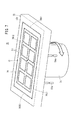
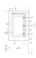
図7に示すように、本発明の第2の実施形態に係る製造方法に使用される製造装置70は、作業テーブル72を備える。作業テーブル72は、回転機構74を介してテーブル面に垂直な軸O回りに回転自在である。作業テーブル72の上面(載置面)72sには、内側吸着ライン(第1吸引機構)54と外側吸着ライン(第2吸引機構)76とが設けられる。軸Oは、内側吸着ライン54及び外側吸着ライン76の中心位置である。
As shown in FIG. 7, the
外側吸着ライン76は、例えば、内側吸着ライン54を周回する長方形状の溝により形成されるとともに、段差MEA10aの平面寸法よりも大きな寸法に形成される。外側吸着ライン76は、2本の長辺ライン76L1、76L2と2本の短辺ライン76S1、76S2とを有し、これらは、それぞれ独立して吸引可能である。
The
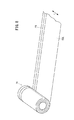
図8に示すように、第2の実施形態では、フィルムロール78が用いられる。フィルムロール78は、長尺なフィルム部材58Lを備え、前記フィルム部材58Lには、幅方向(矢印H方向)一端側に近接して長尺な接着フィルム26Lが設けられるとともに、巻回されている。
As shown in FIG. 8, a
そこで、図9に示すように、段差MEA10aが作業テーブル72の上面72sに載置され、吸引保持されている。フィルムロール78からフィルム部材58Lが繰り出され、接着フィルム26Lが段差MEA10aの所定の貼り付け位置である一方の長辺に沿って配置される。作業テーブル72では、外側吸着ライン76の一方の長辺ライン76L1のみが吸引され、フィルム部材58Lは、段差MEA10aに重なり合って前記作業テーブル72の上面72aに吸引保持される。
Therefore, as shown in FIG. 9, the
その際、図10に示すように、接着フィルム26Lは、一部をカソード電極22の第2ガス拡散層22bの先端縁部に重なり合って固体高分子電解質膜18の露出面18beに配置される。この状態で、図示しないヒータローラにより接着フィルム26Lの所定の長さに亘って加圧加熱処理が施される。さらに、フィルム部材58Lが剥離されることにより、段差MEA10aには、一方の長辺に接着フィルム26S1が貼り付けられる。
At that time, as shown in FIG. 10, the
次いで、図11に示すように、作業テーブル72は、回転機構74を介して軸O回りに90゜だけ回転される。このため、段差MEA10aの次なる貼り付け位置である一方の短辺が、フィルム部材58Lの繰り出し範囲に配置される。そして、作業テーブル72とフィルムロール78との相対位置を調整するために、前記作業テーブル72又は前記フィルムロール78の矢印H方向に対する位置調整がされる。
Next, as shown in FIG. 11, the work table 72 is rotated by 90 ° around the axis O via the
フィルムロール78からフィルム部材58Lが繰り出され、接着フィルム26Lが段差MEA10aの所定の貼り付け位置である一方の短辺に沿って配置される。作業テーブル72では、外側吸着ライン76の一方の短辺ライン76S1のみが吸引され、フィルム部材58Lは、段差MEA10aに重なり合って前記作業テーブル72の上面72sに吸引保持される。
The
この状態で、図示しないヒータローラにより接着フィルム26Lの所定の長さに亘って加圧加熱処理が施される。さらに、フィルム部材58Lが剥離されることにより、段差MEA10aには、一方の短辺に接着フィルム26S2が貼り付けられる。
In this state, pressure heating treatment is performed over a predetermined length of the
図12に示すように、作業テーブル72は、回転機構74を介して軸O回りに90゜だけ回転される。このため、段差MEA10aの次なる貼り付け位置である他方の長辺が、フィルム部材58Lの繰り出し範囲に配置される。そして、作業テーブル72とフィルムロール78との矢印H方向に対する相対位置が調整される。
As shown in FIG. 12, the work table 72 is rotated by 90 ° around the axis O via the
フィルムロール78からフィルム部材58Lが繰り出され、接着フィルム26Lが段差MEA10aの所定の貼り付け位置である他方の長辺に沿って配置される。作業テーブル72では、外側吸着ライン76の他方の長辺ライン76L2のみが吸引され、フィルム部材58Lは、段差MEA10aに重なり合って前記作業テーブル72の上面72sに吸引保持される。
The
この状態で、図示しないヒータローラにより接着フィルム26Lの所定の長さに亘って加圧加熱処理が施される。さらに、フィルム部材58Lが剥離されることにより、段差MEA10aには、他方の長辺に接着フィルム26S3が貼り付けられる。
In this state, pressure heating treatment is performed over a predetermined length of the
図13に示すように、作業テーブル72は、回転機構74を介して軸O回りに90゜だけ回転される。このため、段差MEA10aの次なる貼り付け位置である他方の短辺が、フィルム部材58Lの繰り出し範囲に配置される。そして、作業テーブル72とフィルムロール78との矢印H方向に対する相対位置が調整される。
As shown in FIG. 13, the work table 72 is rotated by 90 ° around the axis O via the
フィルムロール78からフィルム部材58Lが繰り出され、接着フィルム26Lが段差MEA10aの所定の貼り付け位置である他方の短辺に沿って配置される。作業テーブル72では、外側吸着ライン76の他方の短辺ライン76S2のみが吸引され、フィルム部材58Lは、段差MEA10aに重なり合って前記作業テーブル72の上面72sに吸引保持される。
The
この状態で、図示しないヒータローラにより接着フィルム26Lの所定の長さに亘って加圧加熱処理が施される。さらに、フィルム部材58Lが剥離されることにより、段差MEA10aには、他方の短辺に接着フィルム26S4が貼り付けられる。これにより、段差MEA10aには、枠状の接着フィルム26aが設けられる。
In this state, pressure heating treatment is performed over a predetermined length of the
このように、第2の実施形態では、作業テーブル72は、回転機構74を介してテーブル面に垂直な軸O回りに回転自在である。このため、長尺状の接着フィルム26Lが設けられたフィルムロール78を使用して、段差MEA10aに枠状の接着フィルム26aを形成することができる。従って、種々の形状の接着フィルムを容易に形成することが可能になり、汎用性が向上するという効果が得られる。また、隣り合う接着フィルム26aの間の隙間は、後工程の加圧、加熱処理によりなくすことができる。
Thus, in the second embodiment, the work table 72 is rotatable around the axis O perpendicular to the table surface via the
さらに、フィルムロール78を用いることにより、各種フィルムロールをカートリッジのように交換するだけで、他品種に対応することができる。例えば、図14に示すフィルムロール78aを採用することも可能である。フィルムロール78aは、長尺なフィルム部材58Lを備え、前記フィルム部材58Lには、枠状に形成された接着フィルム26aが所定の間隔ずつ離間して設けられるとともに、巻回されている。なお、枠状の接着フィルム26aに代えて、円形状、三角形状又は多角形状の種々の形状の接着フィルムを設けてもよい。すなわち、予め直線及び円形や多角形の接着層が設けられたフィルム部材をロール状に巻回したフィルムロールを用意し、セットするフィルムロールを交換するだけで、他品種のフィルムロールを巻き戻して作業テーブルに繰り出すことができる。
Furthermore, by using the
図15に示すように、本発明の第3の実施形態に係る製造方法では、特に長尺な接着フィルム26S1を段差MEA10aに貼り付ける前に、段差部位のずれ防止を目的として接着層の直線及び円形や多角形を問わず、接着フィルム26Lと前記段差MEA10aとを部分的に接合させる仮止め処理が行われる。具体的には、予め、接着フィルム26Lの所定の位置に、例えば、3カ所に、加圧加熱処理(加圧のみ、又は加熱のみでもよい)が施され、仮止め部82a、82b及び82cが形成される。次いで、図示しないヒータローラ及び接着形状に応じた熱盤により、接着フィルム26Lの所定の長さに亘って加圧加熱処理が施される。
As shown in FIG. 15, in the manufacturing method according to the third embodiment of the present invention, in particular, before the long adhesive film 26S1 is attached to the
このように、第3の実施形態では、段差MEA10aの段差部位に跨って長尺な接着フィルム26S1が設けられる際、貼り付け方向(矢印F方向)に沿って前記接着フィルム26S1に蛇行が発生することを確実に抑制することができる。これにより、接着フィルム26aは、平面だけではなく、段差部位にも高精度に貼り付け可能であるという効果が得られる。
As described above, in the third embodiment, when the long adhesive film 26S1 is provided across the step portion of the
本発明の第4の実施形態に係る製造方法では、例えば、図9、図11〜図13に示す第2の実施形態と同様に、接着フィルム26S1、26S2、26S3及び26S4を段差MEA10aに設けている。
In the manufacturing method according to the fourth embodiment of the present invention, for example, the adhesive films 26S1, 26S2, 26S3, and 26S4 are provided on the
その際、段差MEA10a上の各接着フィルム26S1〜26S4毎に、図9に示すように、接着層始端位置、接着層終端位置及び接着層長さが計測されている。装置内では、図16に示すように、接着フィルム26Lは、計測された情報に基づいて、カット部位80で切断され又は中抜きされ、作業テーブル72上に移送されている。
At that time, as shown in FIG. 9, the adhesive layer start position, the adhesive layer end position, and the adhesive layer length are measured for each of the adhesive films 26S1 to 26S4 on the
このように、第4の実施形態では、段差MEA10a上での各接着層貼り付け部位の位置に合わせて、接着フィルム26Lが切り出されるため、各接着フィルム26S1〜26S4の始端位置を高精度に設定することができ、貼り付け精度の向上が容易に図られる。
Thus, in 4th Embodiment, since
10…樹脂枠付き電解質膜・電極構造体 10a…段差MEA
12…発電セル 14、16…セパレータ
18…固体高分子電解質膜 18be…露出面
20…アノード電極 20a、22a…電極触媒層
20b、22b…ガス拡散層 22…カソード電極
24…樹脂枠部材 26…枠状接着層
26a…接着フィルム 30a…酸化剤ガス入口連通孔
30b…酸化剤ガス出口連通孔 32a…冷却媒体入口連通孔
32b…冷却媒体出口連通孔 34a…燃料ガス入口連通孔
34b…燃料ガス出口連通孔 36…燃料ガス流路
38…酸化剤ガス流路 40…冷却媒体流路
42、44…シール部材 50…製造装置
52…作業テーブル 54…内側吸着ライン
56…外側吸着ライン 58…フィルム部材
62…ヒータローラ
10 ... Electrolyte membrane / electrode structure with
DESCRIPTION OF
Claims (5)
前記固体高分子電解質膜の、前記第2電極の外方に露呈する外周面に、枠状の接着層により接合される樹脂枠部材と、
を有する燃料電池用の樹脂枠付き電解質膜・電極構造体の製造方法であって、
作業テーブル上で、第1吸引機構を介して前記段差MEAを吸引保持する工程と、
前記第1吸引機構により該段差MEAが吸引保持された状態で、前記接着層が設けられたフィルム部材を、第2吸引機構を介して該接着層が該段差MEAに重なり合うように吸引保持する工程と、
前記接着層が前記段差MEAに貼り付けられた後、前記フィルム部材を剥離する工程と、
前記接着層を介して前記段差MEAと前記樹脂枠部材とを接合する工程と、
を有することを特徴とする樹脂枠付き電解質膜・電極構造体の製造方法。 A first electrode is provided on one surface of the solid polymer electrolyte membrane, a second electrode is provided on the other surface of the solid polymer electrolyte membrane, and the planar dimensions of the first electrode are A step MEA set to a dimension larger than the planar dimension of the second electrode;
A resin frame member bonded to the outer peripheral surface of the solid polymer electrolyte membrane exposed to the outside of the second electrode by a frame-shaped adhesive layer;
A method for producing an electrolyte membrane / electrode structure with a resin frame for a fuel cell, comprising:
Sucking and holding the step MEA via a first suction mechanism on a work table;
A step of sucking and holding the film member provided with the adhesive layer via the second suction mechanism so that the adhesive layer overlaps the step MEA while the step MEA is sucked and held by the first suction mechanism. When,
After the adhesive layer is attached to the step MEA, the step of peeling the film member;
Bonding the step MEA and the resin frame member via the adhesive layer;
A process for producing an electrolyte membrane / electrode structure with a resin frame, comprising:
該作業テーブルを、テーブル面に垂直な軸回りに回転させることにより、該接着層の貼り付け位置に対応して前記段差MEAを位置決めする工程と、
を有することを特徴とする樹脂枠付き電解質膜・電極構造体の製造方法。 The manufacturing method according to claim 1, wherein a film roll obtained by winding the film member provided with the adhesive layer in a roll shape is prepared, the film roll is rewound and fed to the work table;
Positioning the step MEA in correspondence with the attachment position of the adhesive layer by rotating the work table about an axis perpendicular to the table surface;
A process for producing an electrolyte membrane / electrode structure with a resin frame, comprising:
前記段差MEA上の接着層始端位置、接着層終端位置及び接着層長さを計測する工程と、
前記接着層を、前記計測された情報に基づいて切断し、前記作業テーブル上に移送する工程と、
を有することを特徴とする樹脂枠付き電解質膜・電極構造体の製造方法。 It is a manufacturing method of Claim 1, Comprising: The process of preparing the film roll which wound the film member provided with the adhesion layer in the shape of a roll, unwinding and feeding out the film roll,
Measuring the adhesive layer start position, adhesive layer end position and adhesive layer length on the step MEA;
Cutting the adhesive layer based on the measured information and transferring the adhesive layer onto the work table;
A process for producing an electrolyte membrane / electrode structure with a resin frame, comprising:
前記固体高分子電解質膜の、前記第2電極の外方に露呈する外周面に、枠状の接着層により接合される樹脂枠部材と、
を有する燃料電池用の樹脂枠付き電解質膜・電極構造体の製造装置であって、
作業テーブル上に前記段差MEAを吸引保持する第1吸引機構と、
前記第1吸引機構により該段差MEAが吸引保持された状態で、前記接着層が設けられたフィルム部材を、該接着層が該段差MEAに重なり合うように吸引保持する第2吸引機構と、
を備えることを特徴とする樹脂枠付き電解質膜・電極構造体の製造装置。 A first electrode is provided on one surface of the solid polymer electrolyte membrane, a second electrode is provided on the other surface of the solid polymer electrolyte membrane, and the planar dimensions of the first electrode are A step MEA set to a dimension larger than the planar dimension of the second electrode;
A resin frame member bonded to the outer peripheral surface of the solid polymer electrolyte membrane exposed to the outside of the second electrode by a frame-shaped adhesive layer;
An apparatus for manufacturing an electrolyte membrane / electrode structure with a resin frame for a fuel cell, comprising:
A first suction mechanism that sucks and holds the step MEA on a work table;
A second suction mechanism that sucks and holds the film member provided with the adhesive layer so that the adhesive layer overlaps the step MEA in a state where the step MEA is sucked and held by the first suction mechanism;
An apparatus for producing an electrolyte membrane / electrode structure with a resin frame, comprising:
Priority Applications (2)
| Application Number | Priority Date | Filing Date | Title |
|---|---|---|---|
| JP2015240874A JP6190865B2 (en) | 2015-12-10 | 2015-12-10 | Manufacturing method and apparatus for manufacturing electrolyte membrane / electrode structure with resin frame |
| US15/373,460 US10593965B2 (en) | 2015-12-10 | 2016-12-09 | Method and apparatus for manufacturing resin-framed membrane electrode assembly |
Applications Claiming Priority (1)
| Application Number | Priority Date | Filing Date | Title |
|---|---|---|---|
| JP2015240874A JP6190865B2 (en) | 2015-12-10 | 2015-12-10 | Manufacturing method and apparatus for manufacturing electrolyte membrane / electrode structure with resin frame |
Publications (2)
| Publication Number | Publication Date |
|---|---|
| JP2017107753A JP2017107753A (en) | 2017-06-15 |
| JP6190865B2 true JP6190865B2 (en) | 2017-08-30 |
Family
ID=59018511
Family Applications (1)
| Application Number | Title | Priority Date | Filing Date |
|---|---|---|---|
| JP2015240874A Active JP6190865B2 (en) | 2015-12-10 | 2015-12-10 | Manufacturing method and apparatus for manufacturing electrolyte membrane / electrode structure with resin frame |
Country Status (2)
| Country | Link |
|---|---|
| US (1) | US10593965B2 (en) |
| JP (1) | JP6190865B2 (en) |
Families Citing this family (2)
| Publication number | Priority date | Publication date | Assignee | Title |
|---|---|---|---|---|
| JP7207353B2 (en) * | 2020-03-12 | 2023-01-18 | トヨタ自動車株式会社 | Fuel cell manufacturing method |
| CN111755724B (en) * | 2020-06-01 | 2021-10-22 | 无锡先导智能装备股份有限公司 | Fuel cell membrane electrode production equipment |
Family Cites Families (12)
| Publication number | Priority date | Publication date | Assignee | Title |
|---|---|---|---|---|
| JPH06103990A (en) * | 1992-09-18 | 1994-04-15 | Ngk Insulators Ltd | Solid electrolytic type fuel cell and manufacture thereof |
| US7011004B2 (en) * | 2001-07-06 | 2006-03-14 | Honda Giken Kogyo Kabushiki Kaisha | Trimming apparatus and method for fuel cell membrane/electrode coupling and transporting apparatus |
| JP2005243565A (en) * | 2004-02-27 | 2005-09-08 | Toshiba Corp | Assembling method and assembling jig of fuel cell |
| US8137741B2 (en) * | 2007-05-10 | 2012-03-20 | Fuelcell Energy, Inc. | System for fabricating a fuel cell component for use with or as part of a fuel cell in a fuel cell stack |
| JP2010238655A (en) * | 2009-03-11 | 2010-10-21 | Takatori Corp | Device of manufacturing fuel cell |
| CN103582562B (en) * | 2011-04-11 | 2015-10-14 | 大日本印刷株式会社 | Polymer electrolyte fuel cells reinforcing material and wherein used adhesion adhesive composition |
| JP5638508B2 (en) | 2011-12-22 | 2014-12-10 | 本田技研工業株式会社 | Manufacturing method of electrolyte membrane / electrode structure with resin frame for fuel cell |
| JP5857929B2 (en) * | 2012-05-01 | 2016-02-10 | トヨタ自動車株式会社 | Fuel cell and fuel cell manufacturing method |
| JP2013239316A (en) * | 2012-05-15 | 2013-11-28 | Honda Motor Co Ltd | Manufacturing method of electrolytic membrane/electrode structure with resin frame for fuel cell |
| JP6104050B2 (en) * | 2012-06-29 | 2017-03-29 | 本田技研工業株式会社 | Electrolyte membrane / electrode structure for fuel cells |
| EP2874217B1 (en) * | 2012-07-10 | 2017-04-19 | Nissan Motor Co., Ltd. | Holding device for fuel cell electrolyte membrane |
| JP6123459B2 (en) | 2013-04-26 | 2017-05-10 | 日産自動車株式会社 | Manufacturing method of membrane electrode assembly |
-
2015
- 2015-12-10 JP JP2015240874A patent/JP6190865B2/en active Active
-
2016
- 2016-12-09 US US15/373,460 patent/US10593965B2/en active Active
Also Published As
| Publication number | Publication date |
|---|---|
| JP2017107753A (en) | 2017-06-15 |
| US20170170493A1 (en) | 2017-06-15 |
| US10593965B2 (en) | 2020-03-17 |
Similar Documents
| Publication | Publication Date | Title |
|---|---|---|
| US9831504B2 (en) | Single fuel cell and method of manufacturing single fuel cell | |
| JP6722574B2 (en) | Electrolyte membrane with resin frame/electrode structure and method for manufacturing the same | |
| JP5321181B2 (en) | Method for producing assembly of catalyst layer and electrolyte membrane of fuel cell member | |
| JP5539540B2 (en) | Transfer device | |
| JP2020140933A (en) | Fuel cell and manufacturing method thereof | |
| CN112825360A (en) | Apparatus and method for manufacturing membrane electrode assembly with auxiliary gasket | |
| JP6190865B2 (en) | Manufacturing method and apparatus for manufacturing electrolyte membrane / electrode structure with resin frame | |
| JP2017068956A (en) | Resin frame-attached electrolyte membrane-electrode structure for fuel cell | |
| JP2017126457A (en) | Method and device for manufacturing resin frame-attached stepped mea | |
| US20210126266A1 (en) | Method for producing an electrochemically active unit and support element for an assembly of an electrochemically active unit | |
| JP2015090793A (en) | Resin frame-attached electrolyte membrane-electrode structure for fuel batteries | |
| JP6602244B2 (en) | Step MEA with resin frame for fuel cell and manufacturing method thereof | |
| CN112820918A (en) | Membrane electrode assembly with auxiliary gasket, and method and apparatus for manufacturing the same | |
| JP6442554B2 (en) | Manufacturing method and apparatus for electrolyte membrane / electrode structure with resin frame | |
| JP6100230B2 (en) | Electrolyte membrane / electrode structure with resin frame for fuel cell and production method thereof | |
| JP6144650B2 (en) | Manufacturing method of fuel cell | |
| JP6442555B2 (en) | Manufacturing method of electrolyte membrane / electrode structure with resin frame | |
| US11962050B2 (en) | Method for producing resin frame equipped membrane electrode assembly | |
| JP2017068908A (en) | Manufacturing method for resin frame-attached electrolyte membrane-electrode structure | |
| CN214898515U (en) | Frame of membrane electrode, fuel cell and processing equipment of frame | |
| WO2021010047A1 (en) | Method for manufacturing membrane-electrode assembly with sub-gasket, device for manufacturing membrane-electrode assembly with sub-gasket, and sub-gasket substrate | |
| JP5466131B2 (en) | Manufacturing method of electrolyte membrane / electrode structure for fuel cell | |
| JP6170883B2 (en) | Method for producing hot melt adhesive | |
| JP2016012435A (en) | Manufacturing method of fuel cell | |
| JP2011222479A (en) | Electrolyte film/electrode structure for fuel cell and manufacturing method thereof |
Legal Events
| Date | Code | Title | Description |
|---|---|---|---|
| A977 | Report on retrieval |
Free format text: JAPANESE INTERMEDIATE CODE: A971007 Effective date: 20170714 |
|
| TRDD | Decision of grant or rejection written | ||
| A01 | Written decision to grant a patent or to grant a registration (utility model) |
Free format text: JAPANESE INTERMEDIATE CODE: A01 Effective date: 20170725 |
|
| A61 | First payment of annual fees (during grant procedure) |
Free format text: JAPANESE INTERMEDIATE CODE: A61 Effective date: 20170807 |
|
| R150 | Certificate of patent or registration of utility model |
Ref document number: 6190865 Country of ref document: JP Free format text: JAPANESE INTERMEDIATE CODE: R150 |