JP6190768B2 - Electron microscope apparatus and imaging method using the same - Google Patents
Electron microscope apparatus and imaging method using the same Download PDFInfo
- Publication number
- JP6190768B2 JP6190768B2 JP2014136874A JP2014136874A JP6190768B2 JP 6190768 B2 JP6190768 B2 JP 6190768B2 JP 2014136874 A JP2014136874 A JP 2014136874A JP 2014136874 A JP2014136874 A JP 2014136874A JP 6190768 B2 JP6190768 B2 JP 6190768B2
- Authority
- JP
- Japan
- Prior art keywords
- image
- field
- narrow
- wide
- region
- Prior art date
- Legal status (The legal status is an assumption and is not a legal conclusion. Google has not performed a legal analysis and makes no representation as to the accuracy of the status listed.)
- Active
Links
Images


Classifications
-
- H—ELECTRICITY
- H01—ELECTRIC ELEMENTS
- H01J—ELECTRIC DISCHARGE TUBES OR DISCHARGE LAMPS
- H01J37/00—Discharge tubes with provision for introducing objects or material to be exposed to the discharge, e.g. for the purpose of examination or processing thereof
- H01J37/26—Electron or ion microscopes; Electron or ion diffraction tubes
- H01J37/261—Details
- H01J37/265—Controlling the tube; circuit arrangements adapted to a particular application not otherwise provided, e.g. bright-field-dark-field illumination
-
- H—ELECTRICITY
- H01—ELECTRIC ELEMENTS
- H01J—ELECTRIC DISCHARGE TUBES OR DISCHARGE LAMPS
- H01J37/00—Discharge tubes with provision for introducing objects or material to be exposed to the discharge, e.g. for the purpose of examination or processing thereof
- H01J37/02—Details
- H01J37/244—Detectors; Associated components or circuits therefor
-
- H—ELECTRICITY
- H01—ELECTRIC ELEMENTS
- H01J—ELECTRIC DISCHARGE TUBES OR DISCHARGE LAMPS
- H01J37/00—Discharge tubes with provision for introducing objects or material to be exposed to the discharge, e.g. for the purpose of examination or processing thereof
- H01J37/26—Electron or ion microscopes; Electron or ion diffraction tubes
- H01J37/261—Details
- H01J37/263—Contrast, resolution or power of penetration
-
- H—ELECTRICITY
- H01—ELECTRIC ELEMENTS
- H01J—ELECTRIC DISCHARGE TUBES OR DISCHARGE LAMPS
- H01J37/00—Discharge tubes with provision for introducing objects or material to be exposed to the discharge, e.g. for the purpose of examination or processing thereof
- H01J37/26—Electron or ion microscopes; Electron or ion diffraction tubes
- H01J37/28—Electron or ion microscopes; Electron or ion diffraction tubes with scanning beams
-
- H—ELECTRICITY
- H01—ELECTRIC ELEMENTS
- H01J—ELECTRIC DISCHARGE TUBES OR DISCHARGE LAMPS
- H01J2237/00—Discharge tubes exposing object to beam, e.g. for analysis treatment, etching, imaging
- H01J2237/22—Treatment of data
- H01J2237/221—Image processing
-
- H—ELECTRICITY
- H01—ELECTRIC ELEMENTS
- H01J—ELECTRIC DISCHARGE TUBES OR DISCHARGE LAMPS
- H01J2237/00—Discharge tubes exposing object to beam, e.g. for analysis treatment, etching, imaging
- H01J2237/245—Detection characterised by the variable being measured
- H01J2237/24592—Inspection and quality control of devices
-
- H—ELECTRICITY
- H01—ELECTRIC ELEMENTS
- H01J—ELECTRIC DISCHARGE TUBES OR DISCHARGE LAMPS
- H01J2237/00—Discharge tubes exposing object to beam, e.g. for analysis treatment, etching, imaging
- H01J2237/26—Electron or ion microscopes
- H01J2237/28—Scanning microscopes
- H01J2237/2809—Scanning microscopes characterised by the imaging problems involved
-
- H—ELECTRICITY
- H01—ELECTRIC ELEMENTS
- H01J—ELECTRIC DISCHARGE TUBES OR DISCHARGE LAMPS
- H01J2237/00—Discharge tubes exposing object to beam, e.g. for analysis treatment, etching, imaging
- H01J2237/26—Electron or ion microscopes
- H01J2237/28—Scanning microscopes
- H01J2237/2813—Scanning microscopes characterised by the application
- H01J2237/2817—Pattern inspection
Landscapes
- Chemical & Material Sciences (AREA)
- Analytical Chemistry (AREA)
- Image Processing (AREA)
- Microscoopes, Condenser (AREA)
Description
本発明は、電子顕微鏡で広視野領域を高画質かつ高速で撮像する電子顕微鏡装置およびそれを用いた撮像方法に関する。 The present invention relates to an electron microscope apparatus that picks up an image of a wide field of view with an electron microscope at high image quality and at high speed, and an imaging method using the same.
電子顕微鏡は、光学顕微鏡に比べて分解能が非常に高く、被観察対象の微細な構造を鮮明に観察するために広く利用されている。電子顕微鏡では、電子ビームを対象試料に照射し、対象試料から放出される、または対象試料を透過する粒子(照射した電子と同種または別種の電子、または電磁波、光子)を検出器にて検出することで、対象試料の画像を取得する。電子顕微鏡の観察対象は、材料、半導体、食品、バイオ、医療分野等、多岐にわたる。 An electron microscope has a very high resolution as compared with an optical microscope, and is widely used to clearly observe a fine structure of an object to be observed. In an electron microscope, an electron beam is irradiated onto a target sample, and particles emitted from the target sample or transmitted through the target sample (electrons of the same type or different from the irradiated electrons, or electromagnetic waves, photons) are detected by a detector. Thus, an image of the target sample is acquired. Electron microscopes have a wide range of observation targets such as materials, semiconductors, food, biotechnology, and medical fields.
電子顕微鏡を用いた検査や解析において、広範囲における構造物の全体像や分布を確認したいといった要求があり、視野が広く多ピクセルの撮像画像(以下、広視野画像)で観察したいというニーズがある。加えて、広視野画像においても、高画質の画像すなわち高分解能,高SN比,低ドリフトの画像が求められる。 In inspection and analysis using an electron microscope, there is a demand for confirming the entire image and distribution of a structure in a wide range, and there is a need to observe a captured image with a wide field of view (hereinafter referred to as a wide field image). In addition, even in a wide-field image, a high-quality image, that is, an image with high resolution, high SN ratio, and low drift is required.
一般的な電子顕微鏡の撮像方法として、高速にスキャンを行って得られた2枚以上の同一視野の画像データを積算(平均)することで画像を取得する高速(フレーム加算)スキャンモードと、低速にスキャンを行って1枚のSN比のよい画像を取得する低速スキャンモードがある。ステージやビームのドリフトの影響は高速スキャンの場合には少ないが、低速スキャンではスキャン中に画像内における構造物の撮像位置がずれるため、画像の歪みが発生する。一方、高速スキャンモードは歪みが少ないが、フレーム間での位置ずれは排除できないため、そのまま画像を積算すると、合成された画像がぼやけるという問題がある。このため、従来は、低倍率で全体の画像を取得した後、詳細に観察したい領域を高い倍率で撮像しなおすといった撮像方式がとられているが、撮像に手間や時間がかかるといった課題があった。 As a general electron microscope imaging method, high-speed (frame addition) scan mode that acquires images by integrating (average) two or more image data of the same field of view obtained by scanning at high speed, and low-speed There is a low-speed scan mode in which a single image with a good S / N ratio is acquired by scanning. Although the influence of the stage and beam drift is small in the case of high-speed scanning, the imaging position of the structure in the image is shifted during the scanning in the low-speed scanning, so that image distortion occurs. On the other hand, although the high-speed scan mode has little distortion, a positional shift between frames cannot be eliminated. Therefore, there is a problem that if the images are added as they are, the synthesized image is blurred. For this reason, conventionally, an imaging method has been used in which an entire image is acquired at a low magnification and then an area to be observed in detail is imaged again at a high magnification. However, there is a problem that imaging takes time and effort. It was.
これら課題に対応する手段として、高画質の広視野画像を撮像する、より高度な撮像方法が提案されている。高度な撮像方法としては、高速スキャンモードと低速スキャンモードを併用した撮像方法がある。例えば、特許文献1では、高速スキャンモードで画像歪みがない参照画像を、参照画像と同倍率,同領域を低速スキャンモードで撮像画像を取得し、参照画像を基準に撮像画像を補正する撮像方法が述べられている。特許文献2では、高速スキャンモードで低倍率の撮像画像を、低速スキャンモードで高倍率の関心領域画像を取得し、関心領域画像の縮小画像を撮像画像に合成する撮像方法が述べられている。 As a means for dealing with these problems, a more advanced imaging method that captures a high-quality wide-field image has been proposed. As an advanced imaging method, there is an imaging method using both a high-speed scan mode and a low-speed scan mode. For example, in Japanese Patent Application Laid-Open No. H10-228561, an imaging method for acquiring a captured image of a reference image without image distortion in the high-speed scan mode at the same magnification as that of the reference image in the low-speed scan mode and correcting the captured image based on the reference image Is stated. Patent Document 2 describes an imaging method in which a low-magnification captured image is acquired in a high-speed scan mode, a high-magnification region-of-interest image is acquired in a low-speed scan mode, and a reduced image of the region-of-interest image is synthesized with the captured image.
特許文献1の方法では、高画質の広視野画像を得ることができる一方で、撮像時間が長いことおよび試料へのダメージが課題となる。また、特許文献2の方法では、短い時間で高画質な関心領域を含む撮像画像を得ることができる一方で、関心領域以外の画質が低いことが課題となる。これより従来法では、短い撮像時間と広視野画像全体における十分な画質を両立することは難しいと言える。 In the method of Patent Document 1, a high-quality wide-field image can be obtained, but long imaging time and damage to the sample are problems. Further, in the method of Patent Document 2, a captured image including a high-quality region of interest can be obtained in a short time, but the image quality other than the region of interest is low. From this, it can be said that it is difficult for the conventional method to achieve both short imaging time and sufficient image quality in the entire wide-field image.
これに対し本発明では、広視野画像の撮像においても関心領域が高画質であることがより重要視されることに着目し、関心領域が高画質であり、かつそれ以外の領域も観察に十分な画質である広視野画像を高速に撮像する電子顕微鏡装置およびそれを用いた撮像方法を提供する。 On the other hand, in the present invention, attention is paid to the fact that the region of interest has high image quality even when capturing a wide-field image, and the region of interest has high image quality, and other regions are sufficient for observation. Provided are an electron microscope apparatus that captures a wide-field image with high image quality at high speed and an imaging method using the same.
上記した課題を解決するために、本発明では、電子顕微鏡装置を、試料に収束させた電子ビームを照射し走査して試料の画像を取得する電子顕微鏡と、この電子顕微鏡で試料の画像を取得するための処理条件を設定する処理部と、電子顕微鏡で取得した試料の画像を処理する画像処理部と、電子顕微鏡で試料の画像を取得するための条件を入力して画像処理部で処理した結果を出力する入出力部と、電子顕微鏡と画像処理部と入出力部とを制御する制御部とを備えて構成し、画像処理部は、電子顕微鏡で試料の画像を取得するための比較的広い視野の広視野領域と、この広視野領域の内部に含まれる比較的狭い視野の狭視野領域とを設定する撮像領域設定部と、この撮像領域設定部で設定した広視野領域と狭視野領域とを電子顕微鏡で取得した広視野画像と狭視野画像との画質改善処理に関するパラメータを決定するパラメータ決定部と、このパラメータ決定部で決定したパラメータに基づいて広視野画像と狭視野画像との画質改善処理を行う画質改善処理部と、この画質改善処理部で画質改善処理を施した広視野領域に対応する画像を合成する画像合成部とを有して構成した。 In order to solve the above-described problems, in the present invention, an electron microscope apparatus acquires an image of a sample by irradiating and scanning an electron beam focused on the sample, and acquires an image of the sample with the electron microscope. A processing unit for setting processing conditions for processing, an image processing unit for processing an image of a sample acquired with an electron microscope, and a condition for acquiring an image of the sample with an electron microscope are input and processed by the image processing unit An input / output unit that outputs the results, and a control unit that controls the electron microscope, the image processing unit, and the input / output unit, and the image processing unit is a relatively An imaging area setting unit for setting a wide field of view with a wide field of view and a narrow field of view with a relatively narrow field of view included in the wide field of view, and a wide field of view and a narrow field of view set by the imaging area setting unit And acquired with an electron microscope A parameter determination unit that determines parameters related to image quality improvement processing between the wide-field image and the narrow-field image, and image quality improvement processing that performs image quality improvement processing between the wide-field image and the narrow-field image based on the parameters determined by the parameter determination unit And an image synthesis unit that synthesizes an image corresponding to the wide field of view subjected to the image quality improvement processing by the image quality improvement processing unit.
また、上記した課題を解決するために、本発明では、電子顕微鏡装置を用いた撮像方法において、電子顕微鏡を用いて試料の画像を取得するための初期条件を設定し、この設定した初期条件に基づいて電子顕微鏡を用いて試料の広視野領域に収束させた電子ビームを照射し走査して試料の広視野画像を取得し、この取得した広視野画像を処理して広視野領域の内部で広視野領域よりも狭い狭視野領域を設定し、電子顕微鏡を用いて試料の設定した狭視野領域に収束させた電子ビームを照射し走査して試料の狭視野画像を取得し、取得した広視野画像と狭視野画像との画質改善パラメータを決定し、この決定した画質改善パラメータを用いて広視野画像と狭視野画像との画質改善処理を行い、この画質改善処理を行った広視野画像と狭視野画像とを合成し、この合成した広視野領域に対応した画像を表示するようにした。 In order to solve the above-described problems, in the present invention, in an imaging method using an electron microscope apparatus, initial conditions for acquiring an image of a sample using an electron microscope are set, and the initial conditions thus set are set. Based on this, the electron beam focused on the wide field area of the sample is irradiated and scanned to acquire a wide field image of the sample, and the acquired wide field image is processed and widened within the wide field area. A narrow-field area narrower than the field-of-view area is set, and an electron beam focused on the sample-set narrow-field area is irradiated and scanned using an electron microscope to obtain a narrow-field image of the sample. The image quality improvement parameters of the image and the narrow-field image are determined, the image quality improvement processing of the wide-field image and the narrow-field image is performed using the determined image quality improvement parameter, and the wide-field image and the narrow-field image subjected to the image quality improvement processing image It was synthesized and to display an image corresponding to the wide-field regions this synthesis.
更にまた、上記した課題を解決するために、本発明では、電子顕微鏡装置を用いた撮像方法において、電子顕微鏡を用いて試料の広視野領域に収束させた電子ビームを低ドーズ量で照射し走査して試料の広視野画像を取得し、この取得した広視野画像から広視野領域の内部に含まれる比較的狭い視野の狭視野領域を設定し、電子顕微鏡を用いて設定した狭視野領域に収束させた電子ビームを高ドーズ量で照射し走査して試料の狭視野画像を取得し、取得した広視野画像と狭視野画像とのそれぞれのノイズ除去パラメータを決定し、この決定したそれぞれのノイズ除去パラメータに基づいて広視野画像と狭視野画像の画質改善処理を行い、この画質改善処理を施した広視野画像を用いて画質改善処理を施した狭視野画像のドリフト補正を行い、このドリフト補正を行った狭視野画像と広視野画像とを合成するようにした。 Furthermore, in order to solve the above-mentioned problems, in the present invention, in an imaging method using an electron microscope apparatus, an electron beam converged on a wide field area of a sample using an electron microscope is irradiated and scanned at a low dose. Then, a wide-field image of the sample is acquired, a narrow-field region with a relatively narrow field included in the wide-field region is set from the acquired wide-field image, and converged to the narrow-field region set using an electron microscope A narrow-field image of the sample is acquired by irradiating the scanned electron beam at a high dose and scanning, and the noise removal parameters of the acquired wide-field image and narrow-field image are determined, and each of the determined noise removal is determined. Perform image quality improvement processing of wide-field images and narrow-field images based on parameters, perform drift correction of narrow-field images that have been subjected to image quality improvement processing using wide-field images that have been subjected to this image quality improvement processing, Of the narrow-field image and the wide-field image subjected to drift correction was to be synthetic.
更にまた、上記した課題を解決するために、本発明では、電子顕微鏡装置を用いた撮像方法において、電子顕微鏡を用いて試料の広視野領域及びこの広視野領域に含まれる狭視野領域に収束させた電子ビームを狭視野領域には比較的高ドーズ量で照射して走査し狭視野領域以外の広視野領域には比較的低ドーズ量で照射して走査することにより試料の狭視野画像を含む広視野画像を1枚のフレーム画像として取得し、このフレーム画像の画質改善処理を行い、この画質改善処理を施したフレーム画像について複数枚の画像をドリフト補正してフレーム加算した画像を取得し、表示するようにした。 Furthermore, in order to solve the above-described problems, in the present invention, in the imaging method using the electron microscope apparatus, the electron microscope is used to converge the wide field region of the sample and the narrow field region included in the wide field region. A narrow-field image of a sample is included by scanning a narrow-field region with a relatively high dose and irradiating and scanning a wide-field region other than the narrow-field region with a relatively low dose. A wide-field image is acquired as one frame image, the image quality improvement processing of this frame image is performed, and an image obtained by adding a frame by drift-correcting a plurality of images for the frame image subjected to this image quality improvement processing is acquired, Displayed.
本発明によれば、電子顕微鏡の撮像に関して、高画質な広視野画像を比較的短時間で取得することが可能となる電子顕微鏡装置及びそれを用いた撮像方法を提供することができる。また、狭視野領域または広視野領域における画素あたりのドーズ量を自動で適切に設定可能となる電子顕微鏡装置及びそれを用いた撮像方法を提供することができる。 ADVANTAGE OF THE INVENTION According to this invention, regarding the imaging of an electron microscope, the electron microscope apparatus which can acquire a high quality wide-field image in a comparatively short time, and the imaging method using the same can be provided. In addition, it is possible to provide an electron microscope apparatus that can automatically and appropriately set a dose amount per pixel in a narrow visual field region or a wide visual field region, and an imaging method using the same.
本発明は、試料に電子を照射して試料の画像を取得する電子顕微鏡に係り、特に広視野画像を高画質かつ比較的短時間で取得する方法およびその装置を提供するもので、以下のような特徴を有する。 The present invention relates to an electron microscope that acquires an image of a sample by irradiating the sample with electrons. In particular, the present invention provides a method and apparatus for acquiring a wide-field image in high image quality and in a relatively short time. It has the following features.
(1)本発明は、広視野領域とこの領域に含まれる1つ以上の狭視野領域の各々の画像(以下、狭視野画像)を広視野画像よりも狭視野画像のほうが撮像画像の1画素に対応する実領域に照射するドーズ量(以下、ドーズ量)が多くなるように撮像し、広視野画像と狭視野画像に対して各領域のドーズ量が少ないほど強い度合でノイズ除去処理しながら合成することを特徴とする。 (1) In the present invention, each image of a wide-field image and one or more narrow-field regions included in this region (hereinafter referred to as a narrow-field image) is a pixel of a captured image in a narrow-field image rather than a wide-field image. While taking an image so that the dose amount (hereinafter referred to as the dose amount) applied to the real area corresponding to is increased, the smaller the dose amount of each area for the wide-field image and the narrow-field image, the stronger the noise removal processing. It is characterized by combining.
これにより、広視野画像は比較的ドーズ量が少なく高速に撮像し、狭視野画像を比較的ドーズ量が多くなるよう撮像するため、撮像時間の短縮が可能となる。また、各領域をドーズ量に応じてノイズ除去処理するため、良好なSN比の合成画像を得ることができる。ここで、狭視野領域とは、広視野画像の中で観察したい試料およびその構造物情報(例えば、試料上に形成された凹凸パターンのエッジ情報など)が多く含まれている領域またはユーザの関心領域のうち1つ以上に設定する領域である。狭視野領域は1つ以上重ねて設定しても良い。また、必ずしも全ての広視野領域および狭視野領域の全領域を撮像する必要はなく、特定の領域の一部を撮像する場合もあり得る。なお、広視野画像および狭視野画像は、高速スキャンモードのように1枚以上の同一領域の画像データを合成することで画像を取得しても良い。 Accordingly, the wide-field image is captured at a high speed with a relatively small dose amount, and the narrow-field image is captured at a relatively large dose amount, so that the imaging time can be shortened. In addition, since each region is subjected to noise removal processing in accordance with the dose amount, a composite image with a good S / N ratio can be obtained. Here, the narrow-field region is a region that contains a large amount of sample information and structure information (for example, edge information of an uneven pattern formed on the sample) to be observed in a wide-field image, or user interest. This is an area set to one or more of the areas. One or more narrow field regions may be set to overlap. In addition, it is not always necessary to image all of the wide field region and the narrow field region, and a part of a specific region may be imaged. Note that the wide-field image and the narrow-field image may be acquired by synthesizing one or more image data of the same region as in the high-speed scan mode.
(2)また、本発明は、ユーザ入力,狭視野画像または広視野画像中の輝度変化から判定した構造物情報のうち1つ以上の情報に基づき、広視野領域または狭視野領域を自動設定することを特徴とする。 (2) In addition, the present invention automatically sets a wide-field region or a narrow-field region based on one or more pieces of information of structure information determined from a user input, a luminance change in a narrow-field image or a wide-field image. It is characterized by that.
これにより、広視野画像における狭視野領域を、また1つ以上の狭視野画像から広視野領域は手動設定するのに比べて、撮像前の条件設定に要する時間を短縮することができる。さらに、ユーザ入力として関心領域や設計データ等を狭視野領域また広視野領域として教示することで、自動設定する領域の設定精度が向上し、より効率的に撮像時間を短縮することが可能となる。また、画像中の輝度変化から判定した構造物情報から領域を自動設定するため、構造が未知の試料に対しても撮像時間の短縮が可能となる。なお、ユーザ入力および自動で設定する広視野領域または狭視野領域の形状は任意である。 Thereby, the time required for setting the conditions before imaging can be shortened compared to manually setting the narrow field region in the wide field image and the wide field region from one or more narrow field images. Furthermore, by teaching the region of interest, design data, etc. as a narrow-field region or a wide-field region as user input, the setting accuracy of the region to be automatically set can be improved, and the imaging time can be shortened more efficiently. . In addition, since the region is automatically set from the structure information determined from the luminance change in the image, the imaging time can be shortened even for a sample whose structure is unknown. Note that the shape of the wide-field region or narrow-field region that is set by user input and automatically is arbitrary.
(3)また、本発明は、構造物情報を用いて、1つ以上の狭視野画像をドリフト補正することを特徴とする。 (3) Further, the present invention is characterized by drift correction of one or more narrow-field images using structure information.
ドリフト量が小さい広視野画像から算出した構造物情報を参照し、広視野画像よりもドリフト量が大きい1つ以上の狭視野画像をドリフト補正することで、1つ以上の狭視野領域においてドリフト量が小さい合成画像を取得することが可能となる。さらに、ドリフト量が小さい第1狭視野画像から算出した構造物情報を参照し、第1狭視野画像に含まれ、第1狭視野画像よりもドリフト量が大きい1つ以上の第2狭視野画像をドリフト補正することで、1つ以上の第2狭視野領域においてドリフト量が小さい合成画像を取得することが可能となる。なお、第2狭視野画像以降も、狭視野画像の中に領域が小さい狭視野画像が含まれる場合、同様にドリフト補正して合成画像を取得することが可能となる。 The drift amount is corrected in one or more narrow-field regions by referring to structure information calculated from a wide-field image with a small drift amount and performing drift correction on one or more narrow-field images having a larger drift amount than the wide-field image. Can be obtained. Further, the structure information calculated from the first narrow-field image having a small drift amount is referred to, and the one or more second narrow-field images are included in the first narrow-field image and have a larger drift amount than the first narrow-field image. It is possible to acquire a composite image with a small drift amount in one or more second narrow visual field regions. Even after the second narrow-field image, when a narrow-field image with a small area is included in the narrow-field image, it is possible to acquire a composite image by performing drift correction similarly.
(4)また、本発明は、画質改善処理した狭視野画像または広視野画像中の輝度変化から画像中の構造物情報を判定することを特徴とする。 (4) Further, the present invention is characterized in that structure information in an image is determined from a luminance change in a narrow-field image or a wide-field image subjected to image quality improvement processing.
狭視野画像または広視野画像において、ドリフト量が小さいほどSN比が低くなるため、画像中の構造物を判定することが困難である。これに対し、画質改善処理によりSN比が向上した画像から画像中の構造物を判定することで、よりドリフト量が小さい画像からより多くの構造物情報を抽出することが可能となる。 In a narrow-field image or a wide-field image, the smaller the drift amount, the lower the SN ratio. Therefore, it is difficult to determine the structure in the image. On the other hand, it is possible to extract more structure information from an image with a smaller drift amount by determining the structure in the image from the image whose SN ratio has been improved by the image quality improvement processing.
(5)また、本発明は、ユーザ入力,構造物情報のうち1つ以上の情報に基づき、倍率,走査方法を自動変更することを特徴とする。 (5) Further, the present invention is characterized in that the magnification and the scanning method are automatically changed based on one or more information among user input and structure information.
ユーザの関心領域または構造物情報が多く含まれている領域は通常倍率で、それ以外の領域は低倍率で撮像することで撮像時間の短縮が可能となる。ここで、撮像時間の短縮とトレードオフとなるが、ユーザの関心領域または構造物情報が多く含まれている領域を高倍率で撮像することも可能となる。また、ユーザ入力または構造物情報から撮像対象の特性および形状に応じた走査方法を自動設定することで、試料の帯電の影響が少ない画像,エッジ部等が鮮明に写っている画像等が撮像可能となる。 It is possible to shorten the imaging time by capturing the region of interest of the user or the region containing a lot of structure information at a normal magnification and capturing the other regions at a low magnification. Here, there is a trade-off with shortening of imaging time, but it is also possible to image a region of interest of the user or a region containing a lot of structure information at a high magnification. In addition, by automatically setting the scanning method according to the characteristics and shape of the imaging target based on user input or structure information, it is possible to capture images that are less affected by the charge of the sample, images with sharp edges, etc. It becomes.
(6)また、本発明は、合成画像の全領域におけるノイズ度合が同程度となるよう合成することを特徴とする。 (6) Further, the present invention is characterized in that the synthesis is performed so that the noise degrees in the entire area of the synthesized image are approximately the same.
これにより、画像全体のSN比が揃った視認性の良い合成画像を得ることができる。なお、画像全体で揃えるSN比は、画像中の試料を観察するのに十分なSN比であれば、画像処理前の各領域における最高のSN比でも良いし、ユーザがあらかじめ教示したSN比などでも良い。 As a result, it is possible to obtain a composite image with good visibility in which the SN ratio of the entire image is uniform. Note that the S / N ratio for the entire image may be the highest S / N ratio in each region before image processing, as long as the S / N ratio is sufficient for observing the sample in the image, or the S / N ratio taught in advance by the user. But it ’s okay.
(7)また、本発明は、ノイズ除去の強度に基づいて、合成画像の各領域における画質改善処理のパラメータを自動調節することを特徴とする。 (7) Further, the present invention is characterized in that the image quality improvement processing parameters in each region of the composite image are automatically adjusted based on the noise removal strength.
ノイズ除去処理によって、各領域のSN比は向上する一方で、エッジ部などの高周波成分の信号は低下する。これに対し、分解能向上処理等で画質改善することで、画像の視認性を向上することが可能となる。さらに、ノイズ除去の強度に基づいて画質改善処理のパラメータを設定することで、合成画像の全領域におけるエッジ部の鮮鋭さ等の画質改善の結果も同程度となり、視認性の良い合成画像を得ることが可能となる。 The noise reduction process improves the SN ratio of each region, while lowering high-frequency component signals such as edges. On the other hand, it is possible to improve the visibility of an image by improving the image quality by a resolution enhancement process or the like. Furthermore, by setting the image quality improvement processing parameters based on the noise removal strength, the result of image quality improvement such as the sharpness of the edge portion in the entire area of the composite image becomes comparable, and a composite image with good visibility is obtained. It becomes possible.
(8)また、本発明は、広視野画像と狭視野画像の合成途中画像を用いて、1つ以上の狭視野画像をドリフト補正することを特徴とする。 (8) In addition, the present invention is characterized in that one or more narrow-field images are drift-corrected using an image in the middle of combining a wide-field image and a narrow-field image.
広視野画像に比べ、広視野画像と第1狭視野画像の合成途中画像の第1狭視野領域はSN比が高く、含まれる輝度情報が多いため、第1狭視野画像に含まれる第2狭視野画像をより精度良くドリフト補正することが可能となる。
以下に、本発明に係る実施の形態について図面を用いて説明する。
Compared with the wide-field image, the first narrow-field region of the intermediate image of the wide-field image and the first narrow-field image has a high SN ratio and contains a lot of luminance information, so the second narrow-field image included in the first narrow-field image It becomes possible to correct the drift of the visual field image with higher accuracy.
Embodiments according to the present invention will be described below with reference to the drawings.
本発明の実施例1を図1〜8を用いて説明する。
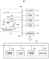
図1は、本発明の一実施形態である走査型電子顕微鏡装置100の基本構成である。走査電子顕微鏡装置100は、例えば、走査型電子顕微鏡101、入出力部121、制御部122、処理部123、記憶部124、画像処理部125を備えて構成される。
A first embodiment of the present invention will be described with reference to FIGS.
FIG. 1 shows a basic configuration of a scanning
電子画像取得装置101では、電子銃102から電子ビーム103を発生し、この電子ビーム103をコンデンサレンズ104や対物レンズ105に通すことにより試料106の表面に集束する。次に、電子ビーム103が照射された試料106から発生する粒子を検出器108で検出することにより、画像を取得する。画像は、記憶部124に保存される。
In the electronic
検出器108は複数個備わっていても良く、さらに、電子を検出する検出器と電磁波を検出する検出器のように異なる粒子を検出する検出器であったり、エネルギーやスピン方向が特定の範囲内にある粒子のみを検出する検出器であったり、2次荷電粒子検出器と後方散乱荷電粒子検出器のように異なる性質の粒子を検出する検出器であっても良い。同じ性質の粒子を検出する検出器が異なる配置位置に複数備わっていても良い。検出器が複数個備わっている場合には、通常1回の撮像で、画像を複数枚取得することができる。
A plurality of
試料106は、ステージ107に搭載されている。ステージ107を移動することにより、試料106の任意の位置における画像の取得が可能である。また、ビーム偏向器109で荷電粒子ビーム103の向きを2次元的に変えることにより、電子ビーム103で試料上を2次元的にスキャン(走査)することができる。
The
入出力部121では、画像撮像位置や撮像条件、画像合成条件の入力、撮像して得た画像や合成画像を画面上に表示したり検査の結果を外部へ送信するなどの出力を行う。制御部122では、撮像装置の制御として、電子銃102に印加する電圧や、コンデンサレンズ104および対物レンズ105の焦点位置、ステージ107の位置、ビーム偏向器109の偏向度合い等を制御する。また、制御部122は、入出力部121、処理部123、記憶部124、画像処理部125の制御も行う。さらに、制御部122は、画像処理部125の撮像領域設定部126で設定する各領域に応じて撮像方法を変更する。
The input / output unit 121 performs input such as input of an image capturing position, image capturing conditions, and image composition conditions, displaying an image obtained by image capturing and a composite image on a screen, and transmitting an inspection result to the outside. The control unit 122 controls the voltage applied to the
処理部123では、各種の処理、例えば、電子ビーム103の焦点を試料106の表面に合わせるために必要な自動焦点合わせに関する処理などを行う。記憶部124では、撮像画像、画質改善後の画像、画像合成における途中結果、各種処理パラメータ等を保存する。画像処理部125では、取得したデータに対する画像処理を行う。
The
画像処理部125は、撮像領域設定部126,パラメータ決定部127、画質改善処理部128、画像合成部129を備えている。撮像領域設定部126では、広視野領域または1つ以上の狭視野領域の設定を行う。パラメータ決定部127では、領域毎の画質改善処理に関するパラメータの決定する処理を行う。画質改善処理部128では、領域毎に画質改善処理を行う。画像合成部129では、各領域の画像のドリフト補正および画像合成処理を行う。画像処理部125はGPU(Graphics Processing Unit)などの高速演算が可能なハードウェアを用いて構成することで、撮像と同時に処理を行うことが可能となり、撮像時間短縮の効果をより高めることができる。
The
図2は、実施例1において図1に示した走査型電子顕微鏡100を用いた処理の流れの概要を示すフロー図であり、広視野画像と狭視野画像に関しドーズ量を変えて撮像し、画質改善処理によって合成後の画像の全領域を観察に十分なSN比に揃えるシーケンスの一実施例を示す図である。
FIG. 2 is a flowchart showing an outline of the flow of processing using the
ステップS201では、撮像領域の自動設定を行うための初期条件を設定する。ユーザは、構造物情報を判定する画像の領域および画質,領域設定のタイプ,撮像対象に関する教示の有無,撮像倍率,関心領域などの設定を行う。ステップS202では、構造物情報を判定する広視野画像を撮像する。なお、初期条件で広視野画像とともに狭視野画像の撮像を設定しても良い。構造物情報を判定する領域は、広視野領域または1つ以上の狭視野領域のうち1つ以上の領域を用いる。なお、初期条件の撮像画像から教示を行う場合は、撮像後に初期条件を追加してもよい。ステップS203では、撮像領域設定部126において、構造物情報およびユーザが設定した関心領域をもとに、1つ以上の狭視野領域を自動設定する。なお、同じ領域に対し狭視野領域を重複して設定する場合もある。この具体的な例については後述する。
In step S201, initial conditions for automatically setting the imaging area are set. The user sets the image area and image quality for determining structure information, the type of area setting, the presence / absence of teaching regarding the imaging target, the imaging magnification, the region of interest, and the like. In step S202, a wide-field image for determining structure information is captured. In addition, you may set imaging of a narrow-field image with a wide-field image on initial conditions. As the region for determining the structure information, one or more of the wide field region or one or more narrow field regions is used. In addition, when teaching is performed from a captured image with initial conditions, the initial conditions may be added after imaging. In step S203, the imaging
ステップS204では、自動設定を行った1つ以上の狭視野領域を撮像する。これらの画像を撮像する順番は任意であるが、ドーズ量は、広視野画像に比べて狭視野画像のドーズ量が多くなるように設定する。このため、狭視野画像は、広視野画像に比べてSN比が高くなる。また、狭視野領域のドーズ量は、例えば、広視野領域に対する狭視野領域の面積が小さいほど、ドーズ量が多くなるように設定する。ここで、ドーズ量が多くなる設定とは、電子ビームのスキャン速度を遅くしたり、照射電流を大きくしたりすることで実現する。同時に画素サイズを小さくすることを組み合わせて、サンプリング誤差を低減してもよい。また、広視野画像および狭視野画像は、高速スキャンモードのように同一領域の画像データを合成した画像で取得してもよい。 In step S204, one or more narrow-field regions that have been automatically set are imaged. The order of capturing these images is arbitrary, but the dose is set so that the dose of the narrow-field image is larger than that of the wide-field image. For this reason, the narrow-field image has a higher SN ratio than the wide-field image. Further, the dose amount of the narrow visual field region is set so that, for example, the smaller the area of the narrow visual field region with respect to the wide visual field region, the larger the dose amount. Here, the setting for increasing the dose is realized by slowing the scanning speed of the electron beam or increasing the irradiation current. Simultaneously reducing the pixel size may reduce the sampling error. Further, the wide-field image and the narrow-field image may be acquired as an image obtained by synthesizing image data of the same region as in the high-speed scan mode.
ステップS205では、パラメータ決定部127において、広視野画像と1つ以上の狭視野画像の領域毎に画質改善パラメータを決定する。ここで、画像処理による画質改善処理としては、ノイズ除去,分解能向上,エッジ強調処理などがある。画質パラメータの決定方法については後述する。ステップS206では、画質改善処理部128において、ステップS205で設定したパラメータ値で領域毎に画質改善処理する。
In step S205, the
ステップS207では、画像合成部129において、ステップS206で画質改善処理した各領域の画像を合成する。画像の合成方法としては、対応する領域に対し、画素値の置換または積算または重み付加算する方法がある。このとき、狭視野画像の画素サイズが広視野画像の画素サイズよりも小さい場合には、広視野画像の画素サイズを狭視野画像の画素サイズに合わせて合成処理を行えばよい。このとき、広視野画像の画素数が増えるが、元の画像の輝度値を補間することで増加分の画素値を決定すればよい。また、合成する画像は、ドリフト補正された画像が好ましい。ステップS208では、ステップS207で合成した画像を表示する。
In step S207, the
これらにより、ユーザの関心領域である狭視野領域だけを、他の領域と比べて多いドーズ量で撮像するため、広視野領域全てを多いドーズ量で撮像する場合に比べ短い撮像時間で全体像と関心領域の高画質画像の取得が可能となる。 As a result, only the narrow field of view, which is the user's area of interest, is imaged with a larger dose than the other areas, so that the entire image can be captured in a shorter imaging time than when the entire wide field of view is imaged with a larger dose. A high-quality image of the region of interest can be acquired.
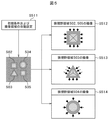
図3A及び図3Bは、ユーザ入力または構造物情報から狭視野領域を自動設定する例を示す一実施例図である。図3A及び図3Bは、図2に示したフローのステップS201〜S203に対応する。 3A and 3B are diagrams illustrating an example in which a narrow field of view is automatically set based on user input or structure information. 3A and 3B correspond to steps S201 to S203 of the flow shown in FIG.
図3Aに示したフロー図は、広視野画像の画像特徴を用いて狭視野領域を設定する例である。ステップS301では、初期条件で指定された広視野画像を撮像し、広視野画像351を取得する。このステップS301は、図2のフロー図のステップS202に対応する。ステップS302では、広視野画像351に対し構造物情報を判別し、構造物情報352を取得する。ステップS302は、図2のフロー図のステップS203に対応する。
The flowchart shown in FIG. 3A is an example of setting a narrow field area using image characteristics of a wide field image. In step S301, a wide-field image designated by the initial condition is captured, and a wide-
ステップS302における構造物情報の判別では、例えば、ラプラシアンフィルタにより広視野画像351に含まれる凹凸パターンのエッジ抽出を行い、エッジで囲われる領域を1,それ以外の領域を0として得られる2値化画像を構造物情報352として出力する。なお、狭視野領域を重複して設定する場合は、第1視野領域に含まれる第2視野領域の判別のため、エッジで囲われる領域の大きさを比較し、構造物情報に対してラべリング処理も行う。ステップS303では、構造物情報352に基づいて広視野画像351に対し狭視野領域353〜356を自動設定する。ステップS303は、図2のフロー図のステップS203に対応する。
In the discrimination of the structure information in step S302, for example, the Laplacian filter performs edge extraction of the concavo-convex pattern included in the wide-
ここで、設定する狭視野領域353〜356は対象となる構造物の周辺を含む範囲とすることで、撮像時の微妙な位置ずれへの対応や、広視野画像との合成を効果的に行うことが可能となる。例えば、構造物情報352に対し膨張処理を施して得られるマスク画像の画素値が1の領域とすればよい。
Here, by setting the
また,図3Aでは、複雑な形状をそのまま狭視野領域として用いる例を示したが、これらを包含する矩形領域を設定してももちろんよい。画像取得においては、電子ビームスキャン条件の設定容易さや画像保存メモリの管理など矩形領域の方が扱いやすいためである。 In FIG. 3A, an example in which a complicated shape is used as it is as a narrow field area is shown. However, a rectangular area including these may be set as a matter of course. This is because in the image acquisition, the rectangular area is easier to handle, such as the ease of setting the electron beam scanning conditions and the management of the image storage memory.
上記の例では、エッジで囲われる領域を狭視野領域として設定したが、ある程度強度の高いエッジの密度を評価して、密度の高い領域を狭視野領域とするなど、他の画像特徴量を用いてももちろんよい。その場合には,テンプレートマッチングではなく、同様の特徴量を持つ領域を狭視野領域として選択すればよい。このようにして設定した狭視野領域について、広視野画像よりもドーズ量の多い条件で狭視野画像を取得することで、関心領域について高い画質の画像を取得することが可能となる。これらを合成することで関心領域のみ画質の高い画像を効率よく取得することが可能となる。 In the above example, the region surrounded by the edge is set as the narrow field of view, but other image feature quantities are used, such as evaluating the density of edges that are somewhat strong and making the region of high density a narrow field of view. Of course. In that case, instead of template matching, an area having a similar feature amount may be selected as the narrow field area. By acquiring a narrow-field image for a narrow-field region set in this way under conditions with a larger dose than a wide-field image, it is possible to acquire a high-quality image for the region of interest. By combining these, it is possible to efficiently acquire an image with high image quality only in the region of interest.
本手法により、画像中の輝度変化から判定した構造物情報に応じた領域を設定するため、広視野領域中の構造物の位置が未知な撮像においても自動で関心領域を狭視野領域として抽出することが可能となる。これにより、広視野領域において狭視野領域をユーザが手動設定し、個別に撮像するのに比べて、撮像前の条件設定に要する時間を短縮することができる。さらに、設定する撮像領域が絞られ、より効率的に撮像時間を短縮することが可能となる。 This method automatically sets the region of interest as a narrow field of view even in imaging where the position of the structure in the wide field of view is unknown, in order to set the region according to the structure information determined from the luminance change in the image. It becomes possible. As a result, the time required for setting the conditions before imaging can be shortened as compared with the case where the user manually sets the narrow field area in the wide field area and individually captures images. Furthermore, the imaging area to be set is narrowed down, and the imaging time can be shortened more efficiently.
別の例として、事前にユーザが関心領域の情報を入力することで狭視野領域を設定する例を、図3Bのフローを用いて説明する。図3BのステップS310では、図3Aで説明したステップS301の初期条件に加えて,ユーザが関心領域を教示画像361として設定する。ステップS310は、図2のフロー図のステップS201とS202に対応する。ステップS311では、広視野画像351は図3AのステップS302の場合と同様に処理され、構造物情報352を取得する。ステップS312では、ステップS302と同様に教示画像361から構造物情報362を取得する。ステップS311とS312及びS313は、図2のフロー図のステップS203に対応する。
As another example, an example in which the user inputs a region of interest information in advance to set a narrow field of view will be described with reference to the flow of FIG. 3B. In step S310 of FIG. 3B, the user sets a region of interest as a
ステップS313では、構造物情報352,362に基づいて広視野画像351に対し狭視野領域363,364を設定する。ステップS313では、ステップS303の前処理で構造物情報362を参照画像として構造物352に対しテンプレートマッチングを行い、マッチした領域363,364のみ領域を設定する。この関心領域である教示画像361は広視野領域から選択してもよいし、別途事前に教示画像361を撮像しておいて、異なる視野で撮像した広視野画像に適用してももちろんよい。
In step S313,
図3Bに示したようなフローで処理を行うことにより、ユーザ入力として撮像対象を教示することで、設定する撮像領域が絞られ、より効率的に撮像時間を短縮することが可能となる。 By performing the processing in the flow as shown in FIG. 3B, the imaging area to be set is narrowed down by teaching the imaging target as the user input, and the imaging time can be shortened more efficiently.
図4は、撮像して取得した広視野画像に対し、画質改善処理を適用し、画質改善後の広視野画像中の輝度変化から構造物情報を判定し、狭視野領域を設定する例を示す図である。図4は、ステップS201〜S203に対応する。画像401は、撮像して取得した広視野画像である。ここで、説明のために、画像402に、画像401に対応する広視野画像の理想画像を示す。
FIG. 4 shows an example in which image quality improvement processing is applied to a wide-field image acquired by imaging, structure information is determined from luminance changes in the wide-field image after image quality improvement, and a narrow-field region is set. FIG. FIG. 4 corresponds to steps S201 to S203. An
ステップS411で画像401に対し、画質改善処理を施し、出力として画質改善した広視野画像403を得る。ステップ411の画質改善処理としては、例えば移動平均フィルタによるノイズ除去,ウィナーフィルタによる画像復元処理などがある。
In step S411, the
ステップS412では、図3AのステップS302の場合と同様に、画像403から構造物情報の判別を行い、構造物情報404を取得する。ここで、ステップS411の画質改善処理により画像403のSN比が向上しているため、画像401でノイズに埋もれていた構造物情報も判別が可能となる。
In step S412, as in step S302 of FIG. 3A, structure information is determined from the
ステップS413では、構造物情報404に基づき、図3AのステップS303と同様に狭視野領域を設定する。図4の例では、図3の例とは別に、狭視野領域が入れ子になる例を示す。これは、狭視野画像中のより微細な構造をより高画質で観察したいときなどに有効である。最終的に、広視野領域に対し、第1狭視野領域405とこれに含まれる第2狭視野領域406を設定する。
In step S413, a narrow visual field region is set based on the
このようにして設定した2段階の狭視野領域について、第1狭視野画像は広視野画像よりもドーズ量の多い条件で、第2狭視野画像は第1狭視野画像より更に多いドーズ量で取得することで、関心領域について高い画質の画像を取得することが可能となる。これらを合成することで関心領域のみ画質の高い画像を効率よく取得することが可能となる。 For the two-stage narrow-field region set in this way, the first narrow-field image is acquired with a larger amount of dose than the wide-field image, and the second narrow-field image is acquired with a larger dose than the first narrow-field image. By doing so, it is possible to acquire a high-quality image for the region of interest. By combining these, it is possible to efficiently acquire an image with high image quality only in the region of interest.
これらにより、低SN比の広視野画像中の構造物を判定することで、よりドリフト量が小さい画像から、より多くの構造物情報を抽出することが可能となる。また、第1狭視野画像に対し、より詳細な輝度情報を取得する第2狭視野画像が設定されるため、構造物に関するより詳細な情報をもつ撮像画像を取得することが可能となる。 As a result, it is possible to extract more structure information from an image with a smaller drift amount by determining the structure in the wide-field image with a low SN ratio. In addition, since the second narrow-field image for acquiring more detailed luminance information is set for the first narrow-field image, it is possible to acquire a captured image having more detailed information about the structure.
図5は、広視野領域の構造物情報から、狭視野領域の画質をよりよく撮像するための走査方法を自動設定し、撮像する例を示す図である。図5は、図2のフロー図のステップS201〜S204に対応する。 FIG. 5 is a diagram illustrating an example in which an image is set by automatically setting a scanning method for better imaging of the image quality of the narrow field area from the structure information of the wide field area. FIG. 5 corresponds to steps S201 to S204 in the flowchart of FIG.
ステップS511は、ステップS201に対応する初期条件の設定で、ユーザが走査方法として、構造物情報から走査方法を決定するよう設定すること以外は、図3Aで説明したステップS301,S302,S303と同様であり、図2で説明した処理フローのステップS201乃至S203に対応する。ステップS511では、領域502〜505を狭視野領域として設定する。
Step S511 is the same as Steps S301, S302, and S303 described with reference to FIG. 3A except that the user sets the initial conditions corresponding to Step S201 and the user sets the scanning method to determine the scanning method from the structure information. This corresponds to steps S201 to S203 of the processing flow described in FIG. In step S511, the
ステップS512〜S514は図2のフローのS204に対応し、ユーザ指定の通り構造物情報をもとに走査方法を設定し、撮像する。ここでは、例えば、エッジ部の構造をより鮮明に撮像するため、構造物のエッジに対し、矢印で示したようにスキャン経路が垂直になるよう設定する。なお、矢印で示されるようにスキャンを開始し、各構造物の重心または重心と各頂点を結ぶ線に到達するまでスキャンする。 Steps S512 to S514 correspond to S204 in the flow of FIG. 2, and a scanning method is set based on the structure information as specified by the user, and imaging is performed. Here, for example, in order to capture the structure of the edge portion more clearly, the scan path is set to be perpendicular to the edge of the structure as indicated by the arrow. Note that scanning is started as indicated by arrows, and scanning is performed until the center of gravity of each structure or a line connecting the center of gravity and each vertex is reached.
図5で説明したような手順で撮像することにより、構造物情報から撮像対象の形状に応じた走査方法を設定することができ、エッジ部等の構造をより鮮明に撮像することが可能となる。 By performing imaging in the procedure described with reference to FIG. 5, it is possible to set a scanning method according to the shape of the imaging target from the structure information, and it is possible to capture the structure of the edge portion and the like more clearly. .
図6Aには、画像合成処理に用いる画像のリストを示す。試料を撮像して取得した広視野画像605とそれに対応する領域602の広視野画像の理想画像601、広視野画像605内の構造物情報606、第1狭視野領域607、第2狭視野領域608の画像を示す。
FIG. 6A shows a list of images used for image composition processing. A wide-
図6Bは、広視野画像と狭視野画像の合成途中画像または広視野画像の構造物情報を用いて、狭視野画像をドリフト補正する例を示す一実施例図である。ドリフト補正を行うことにより、図2のステップS207の画像合成処理の精度があがり、よりよい画質を得ることが可能となる。図6Bは、図2で説明したフロー図のステップS201〜S207に対応する。 FIG. 6B is an example diagram illustrating an example in which drift correction is performed on a narrow-field image using structure information of a wide-field image and a wide-field image or a wide-field image. By performing the drift correction, the accuracy of the image composition processing in step S207 in FIG. 2 is improved, and a better image quality can be obtained. FIG. 6B corresponds to steps S201 to S207 in the flowchart illustrated in FIG.
ステップS651では、図2で説明したフロー図のステップS201〜S206の処理を行う。ステップS202に対応する処理では、低ドリフト量かつ低SN比の広視野画像605を取得する。ステップS203に対応する処理では、広視野画像605から構造物情報606を取得し、第1狭視野領域603および第2狭視野画像604を設定する。ステップS204に対応する処理では、高ドリフト量かつ高SN比の第1狭視野画像607および高ドリフト量かつ高SN比の第2狭視野画像608を取得する。ステップS205,S206に対応する処理では、画像605が高SN比になるよう画質改善処理を施し、低ドリフトかつ高SN比の広視野画像609を取得する。
In step S651, processing in steps S201 to S206 in the flowchart described in FIG. 2 is performed. In the process corresponding to step S202, a wide-
ステップS652では、画像609を参照画像として画像607のドリフト補正を行い、低ドリフト量かつ高SN比の第1狭視野画像610を取得する。ステップS653では、画像609と画像610を合成し、合成途中画像611を取得する。ステップS654では、画像611を参照画像として画像608のドリフト補正を行い、低ドリフト量かつ高SN比の第2狭視野画像612を取得する。ステップS655では、画像611と画像612を合成し、広視野領域の合成画像613を作成する。
In step S652, drift correction of the
ここで、画像607および608は、ドーズ量を多くして時間をかけて1枚の画像を撮像するため、試料ドリフトなどの影響で画像が歪む。このため、1枚の画像の歪みを補正するドリフト補正が必要である。
Here, the
画像の歪みを補正する方法として、次のようなものがある。まず、歪みのない参照画像に対して、歪みがある画像を細かい領域に分割した各画像をテンプレートマッチングして対応する領域を算出する。算出した対応する領域に各テンプレート画像を配置して1枚の画像とし、画像全体で画素の補間処理を行い、画像の歪みを補正した画像を取得する。なお、ドリフト補正の参照画像として、広視野画像609,611の代わりに構造物情報606を用いても良い。また、撮像時間とドリフト補正の精度がトレードオフとなるが、画像607の低ドリフト量かつ中SN比の第1狭視野画像を別にもう一枚撮像し、その構造物情報をドリフト補正の参照画像として、広視野画像609,611の代わりに用いても良い。
There are the following methods for correcting image distortion. First, for a reference image without distortion, each image obtained by dividing an image with distortion into fine areas is subjected to template matching to calculate a corresponding area. Each template image is arranged in the calculated corresponding region to form one image, pixel interpolation processing is performed on the entire image, and an image with corrected image distortion is acquired. Note that the
これらにより、広視野画像609に比べて、広視野画像609と第1狭視野画像610の合成途中画像611の第1狭視野領域(第1狭視野画像610に対応する領域)は分解能が高い上により多くの輝度情報を含むため、第2狭視野画像604をより精度高くドリフト補正することが可能となる。また、ドリフト量が小さい広視野画像605から算出した構造物情報606を参照し、広視野画像609よりもドリフト量が大きい第1狭視野画像607をドリフト補正し、低ドリフト量の第1狭視野画像610を取得することが可能となる。また、撮像時間とトレードオフとなるが、低ドリフト量の第1狭視野画像610から算出した構造物情報(構造物情報606に対応)を参照し、第1狭視野画像610に含まれ、第1狭視野画像610よりも高ドリフト量の第2狭視野画像608をドリフト補正し(S654)、低ドリフト量の第2狭視野画像612を得ることが可能となる。
As a result, the first narrow-field region (the region corresponding to the first narrow-field image 610) of the
図7Aには、合成画像の全領域におけるノイズ度合が同程度となるよう合成する例を示す。図7Aに示した処理は、図2のフロー図におけるステップS201〜S207に対応する。ステップS751では、低ドリフト量かつ低SN比な広視野画像701を取得する。ステップS752,S753では、図3Aで説明したステップS302,S303と同じ処理が行われ、狭視野領域702を設定する。ステップS754では、狭視野領域702を高ドーズ量で撮像し、高ドリフト量かつ高SN比の狭視野画像703を取得する。ステップS755では、領域毎にノイズ除去パラメータを決定する。狭視野画像703に関してSN比が十分である場合、例えば、広視野画像701のみに対して狭視野画像703とノイズ度合が同程度となるようにノイズ除去処理する。
FIG. 7A shows an example in which synthesis is performed so that the degree of noise is the same in all areas of the synthesized image. The process shown in FIG. 7A corresponds to steps S201 to S207 in the flowchart of FIG. In step S751, a wide-
図7Bに移動平均フィルタを用いてノイズ除去処理する場合のパラメータ決定例を示す。ここで、ノイズ除去パラメータは移動平均フィルタの幅である。 FIG. 7B shows an example of parameter determination when performing noise removal processing using a moving average filter. Here, the noise removal parameter is the width of the moving average filter.
まず、ステップS761では、広視野画像から狭視野領域を抽出した画像711のノイズ除去処理に用いる移動平均フィルタの幅を設定する。初期条件のフィルタ幅は、ユーザが指定してもよいし、あらかじめ作成したドーズ量とフィルタ幅のテーブル等から決定してもよい。ステップS762では、画像711に対しノイズ除去処理を行う。
First, in step S761, the width of the moving average filter used for noise removal processing of the
ステップS763では、画像703,画像711をノイズ除去処理した画像のそれぞれに関し、輝度平均値に対する輝度の標準偏差を算出し、画像703の標準偏差から画像711をノイズ除去処理した画像の標準偏差を減算し、差分値を算出する。
In step S763, for each of the
ステップS764では、この差分値の絶対値とあらかじめユーザが設定した基準値を比較する。差分値の絶対値が基準値以下であれば標準偏差は同程度であると判定し、フィルタ幅を決定する。差分値の絶対値が基準値以上であれば、ステップS761に戻ってフィルタ幅を再設定する。フィルタ幅は、差分値が正であれば小さい値を、差分値が負であれば大きい値を設定する。なお、基準値はユーザが指定してもよいし、あらかじめN積み評価を行って得た統計データから決定してもよい。 In step S764, the absolute value of the difference value is compared with a reference value set in advance by the user. If the absolute value of the difference value is less than or equal to the reference value, it is determined that the standard deviation is approximately the same, and the filter width is determined. If the absolute value of the difference value is greater than or equal to the reference value, the process returns to step S761 to reset the filter width. The filter width is set to a small value if the difference value is positive, and to a large value if the difference value is negative. The reference value may be specified by the user, or may be determined from statistical data obtained by performing N-stack evaluation in advance.
以降、ステップS764で差分値の絶対値が基準値以下になるまで、ステップS761〜S763を繰り返す。なお、狭視野画像703に関して、SN比が十分でなくユーザ指定の標準偏差までノイズ度合を抑える場合は、画像711と同様に画像703に関しても、ステップS761〜S764でフィルタ幅を決定すればよい。ただし、この場合、ステップS763において、画像703の標準偏差ではなくユーザ指定の標準偏差から画像703をノイズ除去した画像の標準偏差、または画像711をノイズ除去した画像を減算し、それぞれ差分値を算出する。
Thereafter, steps S761 to S763 are repeated until the absolute value of the difference value becomes equal to or less than the reference value in step S764. In the case of the narrow-
図7AのステップS756では、広視野画像701のみに対し、ステップS755で決定したパラメータ値でノイズ除去処理する。ステップS757では、図6Bで説明したステップS652と同様にノイズ除去処理した広視野画像を参照画像として、狭視野画像をドリフト補正し、ドリフト補正した狭視野画像をノイズ除去処理した広視野画像に合成することで、出力として広視野領域の合成画像704を得る。出力画像は、全領域においては低ドリフト量かつ同程度に高SN比の画像である。なお、ノイズ除去処理だけでなく画像復元処理などを加えることで、ノイズ除去処理を画質改善処理としても良い。
In step S756 of FIG. 7A, noise removal processing is performed on only the wide-
さらに、ノイズ除去パラメータ値に応じて、画質改善パラメータを設定してもよい。例えば、画質改善処理として、ウィナーフィルタによる画像復元処理を行う場合は、ノイズ除去パラメータ値に対応する画像の点広がり関数を推定する必要がある。このためには、エッジ形状を含むサンプル画像に対して、ステップS755のパラメータ値でノイズ除去処理を施し、鈍ったエッジ形状から点広がり関数を推定すればよい。これにより、視野領域702以外の領域におけるノイズ除去処理により低下した分解能が向上し、全領域において分解能も同程度に近づく。
Furthermore, an image quality improvement parameter may be set according to the noise removal parameter value. For example, when image restoration processing using a Wiener filter is performed as image quality improvement processing, it is necessary to estimate a point spread function of an image corresponding to a noise removal parameter value. For this purpose, the sample image including the edge shape may be subjected to noise removal processing with the parameter value in step S755, and the point spread function may be estimated from the dull edge shape. As a result, the resolution reduced by the noise removal processing in the region other than the
これらにより、合成画像の広視野領域と狭視野領域におけるSN比が揃うため、合成画像全体における視認性を向上することが可能となる。さらに、ノイズ除去処理を画質改善処理とすることで、画像704の狭視野領域702以外の領域において、分解能が向上し、広視野領域の合成画像の全領域におけるエッジ部の鮮鋭さも同程度に近づくため、さらに視認性の良い合成画像を得ることが可能となる。
As a result, the S / N ratio in the wide visual field region and the narrow visual field region of the composite image is uniform, so that the visibility in the entire composite image can be improved. Further, by using the image quality improvement processing as the noise removal processing, the resolution is improved in the region other than the narrow-
図8Aは、ドーズ量に応じてノイズ除去パラメータを決定する処理の流れを示す図である。ここでは、図7のステップS755に関する別のパラメータ値の決定方法について示す。ドーズ量が1/k倍になれば、電子顕微鏡において支配的であるショットノイズは標準偏差が√(k)倍になるという関係がある。本実施例では、この関係を利用して、各画像のノイズ度合が同程度になるようにノイズ除去パラメータを設定する。 FIG. 8A is a diagram illustrating a flow of processing for determining a noise removal parameter according to a dose amount. Here, another parameter value determination method related to step S755 of FIG. 7 will be described. If the dose amount becomes 1 / k times, the shot noise that is dominant in the electron microscope has a relationship that the standard deviation becomes √ (k) times. In the present embodiment, using this relationship, the noise removal parameter is set so that the noise degree of each image is approximately the same.
ステップS801は、図7Aで説明したステップS751〜S754と同様である。ただし、図8Bの表810に示したように、狭視野画像811と広視野画像812において、ドーズ量821をそれぞれα,βで撮像し、それぞれのノイズ除去前のノイズ量である輝度平均に対する輝度の標準偏差822がσ(α),σ(β)となった場合について考える。
Step S801 is the same as steps S751 to S754 described in FIG. 7A. However, as shown in Table 810 of FIG. 8B, in the narrow-
ステップS802では、狭視野画像のノイズ除去度合を設定する。例えば、移動平均フィルタによりノイズ除去を行う場合、x,y方向のフィルタ幅をそれぞれt倍に変更すると、フィルタ幅を変更する前の処理結果に対してノイズの標準偏差は1/t倍になる。ここでは、狭視野画像811に関するノイズ除去のフィルタ幅823をsとし、ノイズ除去効果824としてノイズの標準偏差を1/s倍にする。なお、フィルタ幅823は、ユーザが指定してもよいし、予め作成したドーズ量とフィルタ幅のテーブル等から決定してもよい。
In step S802, the noise removal degree of the narrow field image is set. For example, when noise removal is performed using a moving average filter, if the filter width in the x and y directions is changed to t times, the standard deviation of noise becomes 1 / t times the processing result before the filter width is changed. . Here, the noise
ステップS803では、狭視野画像811と広視野画像812のドーズ量821の比を算出する。ここで、ドーズ量821の比をβ/α=1/kとする。なお、上述したドーズ量とノイズ除去前のノイズの標準偏差822の関係よりσ(β)=σ(α)√(k)となる。ステップS804では、ドーズ量821の比に応じて広視野画像812のノイズ除去に用いるフィルタ幅823を決定する。
In step S803, the ratio of the
ここで、上述したフィルタ幅823とノイズ除去効果824の関係より、広視野画像812のドーズ量βが狭視野画像811のドーズ量αの1/k倍である場合には、広視野画像812に対する移動平均フィルタのフィルタ幅823を狭視野画像811の√(k)倍とすることで、ノイズの標準偏差を揃えることができる。図8Bの表810のフィルタ幅823の欄に示すように、広視野画像812に関するフィルタ幅823をs√(k)とすることで、両画像のノイズ除去後のノイズの標準偏差825はともにσ(α)/sとなる。なお、他のノイズ除去処理についても同様の処理が可能である。あるノイズ除去パラメータについて、ノイズ除去効果824が標準偏差に関して処理前と比べて1/sとなるようなパラメータの値をf(s)とする。このf(s)を事前に求めておけばよい。実際、狭視野画像のパラメータ値をf(s)に設定すれば、狭視野画像のノイズの標準偏差は1/s倍に抑えられる。この際、広視野画像のパラメータ値をf(s√(k))に設定すれば、広視野画像のノイズの標準偏差824を1/s√(k)倍に抑えることができ、両画像におけるノイズの標準偏差を合わせることができる。
Here, due to the relationship between the
これらにより、各画像を撮像したドーズ量に応じて、ノイズ除去パラメータを設定することが可能となる。また、図7BのステップS755の例に比べて、合成画像の視認性にほぼ影響ないレベルでノイズの標準偏差の一致度合は低下する可能性はあるが、ループ処理がなく演算量も少ないためノイズ除去パラメータ値を高速に設定することが可能となる Thus, it is possible to set the noise removal parameter according to the dose amount obtained by capturing each image. Compared with the example of step S755 of FIG. 7B, the degree of coincidence of the standard deviation of noise may be reduced at a level that does not substantially affect the visibility of the composite image, but noise is not required because there is no loop processing and the amount of calculation is small. The removal parameter value can be set at high speed.
実施例2が実施例1と異なる点は、各フレーム画像において、狭視野領域およびそれ以外の広視野領域毎にドーズ量を調整して撮像し、フレーム積算画像を取得する点にある。また、実施例2が実施例1と異なる点は、次のフレーム画像で生じ得る最大ドリフト量分だけ構造物よりも大きく狭視野領域を設定および更新し、次のフレーム画像を取得する点にある。実施例2において用いる走査電子顕微鏡装置は、実施例1において図1を用いて説明した走査電子顕微鏡装置100と同じであるので、装置構成の説明を省略する。実施例2が実施例1と異なる点について図9及び図10を用いて説明する。
The second embodiment differs from the first embodiment in that each frame image is imaged by adjusting the dose amount for each of the narrow visual field region and the other wide visual field region, thereby obtaining a frame integrated image. Further, the second embodiment is different from the first embodiment in that the next frame image is acquired by setting and updating a narrow visual field region larger than the structure by the maximum drift amount that can occur in the next frame image. . The scanning electron microscope apparatus used in the second embodiment is the same as the scanning
図9は、実施例2の処理の流れを示す図であり、各フレーム画像において、狭視野領域およびそれ以外の広視野領域毎にドーズ量を調整して撮像し、フレーム積算画像を取得する例を示す一実施例図である。 FIG. 9 is a diagram illustrating a processing flow of the second embodiment. In each frame image, an image is acquired by adjusting the dose amount for each of the narrow visual field region and the other wide visual field region, and acquiring a frame integrated image. It is one Example figure which shows.
ステップS901では、低ドリフト量かつ低SN比の広視野画像を取得し、狭視野領域の初期領域を設定する。ステップS902では、ユーザが指定するフレーム積算数だけステップS903〜S909をループ処理する。ステップS903では、狭視野領域とそれ以外の領域毎にドーズ量を調節して撮像し、現フレーム画像を取得する。ステップS904では、領域毎に画質改善パラメータを決定する。ステップS905では、領域毎に画質改善処理を行う。ステップS906では、画質改善した現フレーム画像に対し、構造物情報の判定を行い、次のフレーム画像で生じ得る最大ドリフト量分だけ構造物よりも大きく狭視野領域を設定し、更新する。ステップS907では、フレーム積算画像を参照画像として現フレーム画像をドリフト補正し、ドリフト補正された現フレーム画像を得る。 In step S901, a wide-field image with a low drift amount and a low SN ratio is acquired, and an initial region of a narrow-field region is set. In step S902, steps S903 to S909 are loop-processed for the number of integrated frames specified by the user. In step S903, the current frame image is acquired by adjusting the dose for each of the narrow visual field region and the other region. In step S904, an image quality improvement parameter is determined for each region. In step S905, image quality improvement processing is performed for each region. In step S906, the structure information is determined for the current frame image whose image quality has been improved, and a narrow-field region larger than the structure is set and updated by the maximum drift amount that can occur in the next frame image. In step S907, the current frame image is drift-corrected using the frame integrated image as a reference image, and a drift-corrected current frame image is obtained.
ここで、複数のフレーム画像を積算して取得するフレーム積算画像では、フレーム間で試料ドリフトなどの影響があると画像がぼやける。このため、フレーム間の位置ずれを補正するドリフト補正が必要である。位置ずれを補正する方法としては、画像間で画像全体の相対位置を変えて輝度値の最小自乗誤差を指標にマッチングを行って最小自乗誤差が最小となる位置を算出し、位置ずれを補正する方法がある。ステップS908では、フレーム積算画像に対し、現フレーム画像を積算する。ステップS909では、参照画像をステップS908で取得したフレーム積算画像で更新する。ステップS910では、フレーム積算数がNであればループ処理を終了する。最後に、ステップS911で最終的なフレーム積算画像を表示する。 Here, in the frame integration image obtained by integrating a plurality of frame images, the image is blurred if there is an influence of sample drift between frames. For this reason, drift correction for correcting the positional deviation between frames is necessary. As a method of correcting misalignment, the relative position of the entire image is changed between images, matching is performed using the least square error of the luminance value as an index, the position where the least square error is minimized, and the misalignment is corrected. There is a way. In step S908, the current frame image is integrated with respect to the frame integrated image. In step S909, the reference image is updated with the frame integration image acquired in step S908. In step S910, if the total number of frames is N, the loop process ends. Finally, in step S911, a final frame integrated image is displayed.
これらにより、フレーム積算数が少なくても十分なSN比のフレーム積算画像を得ることが可能となる。また、照射するドーズ量が多い狭視野領域においてはSN比が高くなるため、単に広視野画像をドリフト補正してフレーム積算した画像に比べて、狭視野領域におけるドリフト補正の精度を向上することが可能となる。 As a result, it is possible to obtain a frame integration image having a sufficient SN ratio even if the number of frame integrations is small. In addition, since the SN ratio is high in a narrow visual field region where the dose to be irradiated is large, the accuracy of drift correction in the narrow visual field region can be improved as compared to an image obtained by simply performing drift correction on a wide field image and integrating the frames. It becomes possible.
図10は、各フレーム画像間で、構造物情報と最大ドリフト量を加味して狭視野領域を更新する例を示す一実施例図である。図10の画像中にはドリフトによる構造物の移動がわかりやすいように中心線が描かれている。画像1001は、前フレーム画像であり、構造物が中心に位置している画像である。ステップS1051では、前フレーム画像の構造物情報を判定し、あらかじめユーザ入力したフレーム間で生じ得る最大ドリフト量分1003だけ構造物情報よりも大きく狭視野領域1002を設定し、更新する。ステップS1052では、狭視野領域1002とこれ以外の領域毎にドーズ量を調整して撮像し、現フレーム画像1004を取得する。ここで、画像1004中の構造物は狭視野領域1002に全て含まれる。また、一様なドーズ量を照射して画像1004を撮像する場合、広視野領域を一定のスキャン速度で撮像する場合に比べて、矢印1013,1014で示すように狭視野領域以外のスキャン速度は速く、狭視野領域のスキャン速度は遅く設定する。ステップS1053では、ステップS1051と同様に狭視野領域を領域1005に更新する。ここで、現フレーム画像では、前フレーム画像に比べ構造物が広視野領域の中心から左上にドリフトしているため、狭視野領域もドリフトに応じて平行移動している。次フレーム画像以降も、ステップS1054で次フレーム画像1006を取得し、ステップS1055で狭視野領域1007の更新を順次行う。
FIG. 10 is an example diagram illustrating an example in which the narrow field of view is updated between the frame images in consideration of the structure information and the maximum drift amount. A center line is drawn in the image of FIG. 10 so that the movement of the structure due to drift is easily understood. The
これらにより、フレーム間で試料がドリフトにより移動する場合でも、適切な狭視野領域を設定することが可能となる。また、一様なドーズ量を照射して取得したフレーム画像に対し、ユーザの関心領域である狭視野領域において多くドーズ量を照射し、より多くの優位な輝度情報をもつフレーム画像を得ることが可能となる。 Thus, even when the sample moves due to drift between frames, it is possible to set an appropriate narrow visual field region. In addition, a frame image obtained by irradiating a uniform dose amount is irradiated with a large amount of dose in a narrow field of view that is a user's region of interest, thereby obtaining a frame image having more dominant luminance information. It becomes possible.
以上、本発明者によってなされた発明を実施の形態に基づき具体的に説明したが、本発明は前記実施の形態に限定されるものではなく、その要旨を逸脱しない範囲で種々変更可能であることはいうまでもない。特に、本発明は広視野領域に限らず、従来一般的に用いられる通常サイズの撮像においても、発明の効果は有効である。 As mentioned above, the invention made by the present inventor has been specifically described based on the embodiment. However, the present invention is not limited to the embodiment, and various modifications can be made without departing from the scope of the invention. Needless to say. In particular, the present invention is not limited to a wide field of view, and the effect of the invention is effective even in normal-size imaging that is conventionally used.
100・・・走査電子顕微鏡装置 101・・・走査型電子顕微鏡 121・・・入出力部 122・・・制御部 123・・・処理部 124・・・記憶部 125・・・画像処理部 126・・・撮像領域設定部 127・・・パラメータ決定部 128・・・画質改善処理部 129・・・画像合成部。
DESCRIPTION OF
Claims (16)
前記試料の画像を取得するための処理条件を設定する処理部と、
前記取得した前記試料の画像を処理する画像処理部と、
前記試料の画像を取得するための条件を入力し、前記画像処理部で処理した結果を出力
する入出力部と、
前記画像処理部と前記入出力部とを制御する制御部とを備え、
前記画像処理部は、
前記試料の画像を取得するための比較的広い視野の広視野領域と、該広視野領域の内部
に含まれる1つ以上の比較的狭い視野の狭視野領域とを設定し、前記広視野領域と前記狭
視野領域とを撮像して取得する広視野画像と狭視野画像の画素あたりのドーズ量が前記広
視野画像よりも前記狭視野画像のほうが多くなるように設定する撮像領域設定部と、
前記広視野領域と前記狭視野領域との画質改善処理に関するパラメータを各領域の画素
あたりのドーズ量に応じて決定するパラメータ決定部と、
該パラメータ決定部で決定したパラメータに基づいて前記広視野画像と前記狭視野画像との画質改善処理を行う画質改善処理部と、
該画質改善処理部で画質改善処理して画像を合成する画像合成部と
を有することを特徴とする電子顕微鏡装置。 In an electron microscope that obtains an image of the sample by irradiating a focused electron beam on the sample,
A processing unit for setting processing conditions for acquiring an image of the sample;
An image processing unit for processing the acquired image of the sample;
An input / output unit that inputs a condition for acquiring an image of the sample and outputs a result processed by the image processing unit;
A control unit for controlling the image processing unit and the input / output unit;
The image processing unit
A wide field region having a relatively wide field of view for acquiring an image of the sample, and one or more narrow field regions having a relatively narrow field of view included in the wide field region; An imaging region setting unit that sets the wide-field image acquired by imaging the narrow-field region and a dose amount per pixel of the narrow-field image so that the narrow-field image is larger than the wide-field image;
A parameter determining unit that determines a parameter related to image quality improvement processing of the wide-field region and the narrow-field region according to a dose amount per pixel of each region;
An image quality improvement processing unit which performs image quality improvement processing of the narrow-field image and the wide-field image based on the parameter determined by said parameter determination unit,
An electron microscope apparatus comprising: an image composition unit configured to compose an image by performing image quality improvement processing in the image quality improvement processing unit.
前記広視野画像中の輝度値の変化から判定した構造物情報のうち1つ以上の情報に基づい
て前記広視野領域または前記狭視野領域を設定することを特徴とする請求項1記載の電子
顕微鏡装置。 The imaging region setting unit is configured to detect the wide field of view based on one or more pieces of information of structure information determined from a user input, a brightness value change in the narrow field image or the wide field image acquired by the electron microscope. The electron microscope apparatus according to claim 1, wherein the region or the narrow field region is set.
造物情報のうち1つ以上の情報に基づき、前記撮像領域設定部で設定した前記広視野領域
と前記狭視野領域における前記ドーズ量,倍率,走査方法に関する撮像条件を設定するこ
とを特徴とする請求項2記載の電子顕微鏡装置。 The processing unit, as a processing condition for acquiring an image of the sample, based on one or more information among user input and the structure information, the wide-field region and the narrow-field region set by the imaging region setting unit The electron microscope apparatus according to claim 2 , wherein imaging conditions relating to the dose amount, magnification, and scanning method in a visual field region are set.
質改善処理のパラメータを設定することを特徴とする請求項1記載の電子顕微鏡装置。 The electron microscope apparatus according to claim 1, wherein the parameter determination unit sets parameters for image quality improvement processing in each region of the composite image based on noise removal strength.
領域におけるノイズ度合が同程度となるようパラメータを決定することを特徴とする請求
項1記載の電子顕微鏡装置。 2. The electron microscope according to claim 1, wherein the parameter determination unit determines the parameter so that the noise degree in the entire region of the combined image of the wide-field image and one or more narrow-field images is approximately the same. apparatus.
た撮像方法であって、
試料の画像を取得するための初期条件を設定し、
該設定した初期条件に基づいて前記試料の広視野領域と前記広視野領域の内部に含まれ
る1つ以上の比較的狭い狭視野領域を設定し、
前記広視野領域と前記狭視野領域とを撮像して取得する広視野画像と狭視野画像の画素
あたりのドーズ量が前記広視野画像よりも前記狭視野画像のほうが多くなるように設定し
、
前記撮像して取得する前記広視野領域と前記狭視野領域との画像の画質改善パラメータを各領域の画素あたりのドーズ量に応じて決定し、
該決定した画質改善パラメータを用いて、前記広視野領域と前記狭視野領域との画像の画質改善処理を行い、
該画質改善処理を行った前記広視野領域と前記狭視野領域との画像を合成する
ことを特徴とする電子顕微鏡装置を用いた撮像方法。 An imaging method using an electron microscope apparatus that acquires an image of the sample by irradiating an electron beam focused on the sample,
Set the initial conditions for acquiring the sample image,
Based on the set initial conditions, a wide field region of the sample and one or more relatively narrow narrow field regions included in the wide field region,
The wide-field image acquired by imaging the wide-field region and the narrow-field region and the dose amount per pixel of the narrow-field image is set so that the narrow-field image is larger than the wide-field image,
The image quality improvement parameter of the image of the wide-field region and the narrow-field region acquired by the imaging determined according to the dose per pixel of each area,
Using the image quality improvement parameter the determined performs image quality improvement processing of the image of the wide-field region and the narrow viewing region,
An imaging method using an electron microscope apparatus, wherein the images of the wide-field region and the narrow-field region subjected to the image quality improvement processing are synthesized.
1つ以上の情報に基づき、前記設定した前記広視野領域と前記狭視野領域における前記ド
ーズ量,倍率,走査方法に関する撮像条件を設定することを特徴とする請求項9記載の電
子顕微鏡装置を用いた撮像方法。 As processing conditions for acquiring the image of the sample, based on one or more information of user input and the structure information, the dose amount, magnification, and scanning in the set wide-field region and narrow-field region The imaging method using the electron microscope apparatus according to claim 9, wherein imaging conditions relating to the method are set.
全領域におけるノイズ度合が同程度となるよう決定することを特徴とする請求項8記載の
電子顕微鏡装置を用いた撮像方法。 9. The electron microscope apparatus according to claim 8, wherein the image quality improvement parameter is determined so that a degree of noise in all regions of a composite image of the wide-field image and one or more narrow-field images is approximately the same. The imaging method used.
を前記狭視野領域には比較的高ドーズ量で照射し前記狭視野領域以外の前記広視野領域に
は比較的低ドーズ量で照射することにより前記試料の狭視野画像を含む広視野画像をフレ
ーム画像として取得し、
該取得したフレーム画像の画質改善処理を行い、
該画質改善処理を施したフレーム画像について複数枚の画像をドリフト補正してフレー
ム加算する
ことを特徴とする電子顕微鏡装置を用いた撮像方法。 The narrow viewing area electron beam is converged to and irradiated with a relatively high dose is in the narrow viewing region and the wide viewing area other than the narrow viewing area included in a wide viewing area and wide-viewing area of the specimen is A wide-field image including a narrow-field image of the sample is obtained as a frame image by irradiating with a relatively low dose,
Perform image quality improvement processing of the acquired frame image,
An imaging method using an electron microscope apparatus, wherein drift correction is performed on a plurality of images for a frame image subjected to the image quality improvement processing and frame addition is performed.
Priority Applications (5)
| Application Number | Priority Date | Filing Date | Title |
|---|---|---|---|
| JP2014136874A JP6190768B2 (en) | 2014-07-02 | 2014-07-02 | Electron microscope apparatus and imaging method using the same |
| US15/312,866 US9824853B2 (en) | 2014-07-02 | 2015-05-27 | Electron microscope device and imaging method using same |
| PCT/JP2015/065319 WO2016002397A1 (en) | 2014-07-02 | 2015-05-27 | Electron microscope device and imaging method using same |
| CN201580027482.2A CN106415774B (en) | 2014-07-02 | 2015-05-27 | Electron microscopic lens device and the image pickup method using the electron microscopic lens device |
| DE112015001902.2T DE112015001902B4 (en) | 2014-07-02 | 2015-05-27 | Electron microscope apparatus and imaging method using it |
Applications Claiming Priority (1)
| Application Number | Priority Date | Filing Date | Title |
|---|---|---|---|
| JP2014136874A JP6190768B2 (en) | 2014-07-02 | 2014-07-02 | Electron microscope apparatus and imaging method using the same |
Publications (3)
| Publication Number | Publication Date |
|---|---|
| JP2016015252A JP2016015252A (en) | 2016-01-28 |
| JP2016015252A5 JP2016015252A5 (en) | 2016-12-22 |
| JP6190768B2 true JP6190768B2 (en) | 2017-08-30 |
Family
ID=55018950
Family Applications (1)
| Application Number | Title | Priority Date | Filing Date |
|---|---|---|---|
| JP2014136874A Active JP6190768B2 (en) | 2014-07-02 | 2014-07-02 | Electron microscope apparatus and imaging method using the same |
Country Status (5)
| Country | Link |
|---|---|
| US (1) | US9824853B2 (en) |
| JP (1) | JP6190768B2 (en) |
| CN (1) | CN106415774B (en) |
| DE (1) | DE112015001902B4 (en) |
| WO (1) | WO2016002397A1 (en) |
Families Citing this family (10)
| Publication number | Priority date | Publication date | Assignee | Title |
|---|---|---|---|---|
| CA2995719A1 (en) * | 2014-08-18 | 2016-02-25 | Viewsiq Inc. | System and method for embedded images in large field-of-view microscopic scans |
| WO2017034976A1 (en) * | 2015-08-21 | 2017-03-02 | Cummins Filtration Ip, Inc. | High speed rotating crankcase ventilation filter media and media pack |
| US10682601B2 (en) | 2015-08-28 | 2020-06-16 | Cummins Filtration Ip, Inc. | Rotating coalescing element with directed liquid drainage and gas outlet |
| JP6391170B2 (en) * | 2015-09-03 | 2018-09-19 | 東芝メモリ株式会社 | Inspection device |
| US10096097B2 (en) * | 2016-08-01 | 2018-10-09 | The United States Of America As Represented By The Secretary Of The Navy | Content-aware bidirectional image edge highlighting |
| JP7107653B2 (en) * | 2017-08-31 | 2022-07-27 | 東レエンジニアリング先端半導体Miテクノロジー株式会社 | Image generation method |
| JP7171010B2 (en) * | 2018-03-07 | 2022-11-15 | 株式会社日立ハイテクサイエンス | Cross-section processing observation device, cross-section processing observation method and program |
| EP3598474A1 (en) | 2018-07-19 | 2020-01-22 | FEI Company | Adaptive specimen image acquisition using an artificial neural network |
| CN109087293B (en) * | 2018-07-27 | 2020-10-16 | 新华三大数据技术有限公司 | Method and device for adjusting imaging parameters of electron microscope |
| US11164721B2 (en) | 2019-03-28 | 2021-11-02 | Massachusetts Institute Of Technology | System and method for learning-guided electron microscopy |
Family Cites Families (15)
| Publication number | Priority date | Publication date | Assignee | Title |
|---|---|---|---|---|
| JPH0562630A (en) * | 1991-08-30 | 1993-03-12 | Jeol Ltd | Electron microscope with plural record positions |
| SG92679A1 (en) * | 2000-02-29 | 2002-11-19 | Inst Materials Research & Eng | Selective deposition of a particle beam based on charging characteristics of a sample |
| JP4334801B2 (en) * | 2000-03-06 | 2009-09-30 | オリンパス株式会社 | Pattern forming member applied to sectioning image observation apparatus and sectioning image observation apparatus using the same |
| US7634061B1 (en) * | 2004-03-26 | 2009-12-15 | Nova R & D, Inc. | High resolution imaging system |
| JP2011033423A (en) * | 2009-07-31 | 2011-02-17 | Hitachi High-Technologies Corp | Pattern shape selection method and pattern measuring device |
| JP5188529B2 (en) * | 2010-03-30 | 2013-04-24 | 株式会社日立ハイテクノロジーズ | Electron beam irradiation method and scanning electron microscope |
| JP5324534B2 (en) * | 2010-07-29 | 2013-10-23 | 株式会社日立ハイテクノロジーズ | Inspection method and apparatus |
| JP5537460B2 (en) * | 2011-02-17 | 2014-07-02 | 株式会社日立ハイテクノロジーズ | Charged particle beam microscope and measurement image correction method using the same |
| JP5537488B2 (en) * | 2011-04-15 | 2014-07-02 | 株式会社日立ハイテクノロジーズ | Charged particle microscope apparatus and image capturing method |
| JP2012226874A (en) * | 2011-04-15 | 2012-11-15 | Ccs Inc | Reflection type lighting device |
| WO2012155267A1 (en) * | 2011-05-13 | 2012-11-22 | Fibics Incorporated | Microscopy imaging method and system |
| JP5712074B2 (en) * | 2011-07-20 | 2015-05-07 | 株式会社日立ハイテクノロジーズ | Scanning transmission electron microscope |
| JP2014029460A (en) * | 2012-07-05 | 2014-02-13 | Canon Inc | Microscope device, and control method therefor |
| US9390887B2 (en) * | 2013-09-17 | 2016-07-12 | Kla-Tencor Corporation | Non-invasive charged particle beam monitor |
| JP6242745B2 (en) * | 2014-05-13 | 2017-12-06 | 株式会社日立ハイテクノロジーズ | Charged particle beam apparatus and inspection method using the apparatus |
-
2014
- 2014-07-02 JP JP2014136874A patent/JP6190768B2/en active Active
-
2015
- 2015-05-27 US US15/312,866 patent/US9824853B2/en active Active
- 2015-05-27 DE DE112015001902.2T patent/DE112015001902B4/en active Active
- 2015-05-27 WO PCT/JP2015/065319 patent/WO2016002397A1/en active Application Filing
- 2015-05-27 CN CN201580027482.2A patent/CN106415774B/en active Active
Also Published As
| Publication number | Publication date |
|---|---|
| CN106415774B (en) | 2017-12-15 |
| JP2016015252A (en) | 2016-01-28 |
| DE112015001902T5 (en) | 2017-02-02 |
| DE112015001902B4 (en) | 2021-01-21 |
| US9824853B2 (en) | 2017-11-21 |
| US20170169992A1 (en) | 2017-06-15 |
| WO2016002397A1 (en) | 2016-01-07 |
| CN106415774A (en) | 2017-02-15 |
Similar Documents
| Publication | Publication Date | Title |
|---|---|---|
| JP6190768B2 (en) | Electron microscope apparatus and imaging method using the same | |
| JP5422673B2 (en) | Charged particle beam microscope and measuring method using the same | |
| JP2014207110A (en) | Observation apparatus and observation method | |
| JP5537488B2 (en) | Charged particle microscope apparatus and image capturing method | |
| JP5164754B2 (en) | Scanning charged particle microscope apparatus and processing method of image acquired by scanning charged particle microscope apparatus | |
| JP4857101B2 (en) | Probe evaluation method | |
| US10623627B2 (en) | System for generating a synthetic 2D image with an enhanced depth of field of a biological sample | |
| WO2016121265A1 (en) | Sample observation method and sample observation device | |
| US7598492B1 (en) | Charged particle microscopy using super resolution | |
| JP5775948B2 (en) | Charged particle microscope apparatus and image capturing method | |
| US11256078B2 (en) | Continuous scanning for localization microscopy | |
| JP6302785B2 (en) | Image quality improvement method and apparatus for scanning charged particle microscope image | |
| US9859093B2 (en) | Method of improving quality of scanning charged particle microscope image, and scanning charged particle microscope apparatus | |
| JP2013188361A (en) | Image processing apparatus | |
| US9396906B2 (en) | Transmission electron microscope and method of displaying TEM images | |
| Mehendale et al. | Image fusion using adaptive thresholding and cross filtering | |
| Chantara et al. | Focus Measure of light field image using modified Laplacian and weighted harmonic variance | |
| JP2009277618A (en) | Magnetic domain structural image acquisition method and scanning transmission electron microscope | |
| Cao et al. | Automatic system for electron tomography data collection in the ultra-high voltage electron microscope | |
| JP2004117208A (en) | Pattern measurement device, pattern measurement method, and program | |
| Kharfi et al. | Temporal and Spatial Resolution Limit Study of Radiation Imaging Systems: Notions and Elements of Super Resolution | |
| CN105939471A (en) | Image processing apparatus, image pickup apparatus and image processing method | |
| JP2016091814A (en) | Electron microscope and image formation method |
Legal Events
| Date | Code | Title | Description |
|---|---|---|---|
| A521 | Request for written amendment filed |
Free format text: JAPANESE INTERMEDIATE CODE: A523 Effective date: 20161107 |
|
| A621 | Written request for application examination |
Free format text: JAPANESE INTERMEDIATE CODE: A621 Effective date: 20161107 |
|
| TRDD | Decision of grant or rejection written | ||
| A01 | Written decision to grant a patent or to grant a registration (utility model) |
Free format text: JAPANESE INTERMEDIATE CODE: A01 Effective date: 20170725 |
|
| A61 | First payment of annual fees (during grant procedure) |
Free format text: JAPANESE INTERMEDIATE CODE: A61 Effective date: 20170807 |
|
| R150 | Certificate of patent or registration of utility model |
Ref document number: 6190768 Country of ref document: JP Free format text: JAPANESE INTERMEDIATE CODE: R150 |
|
| S531 | Written request for registration of change of domicile |
Free format text: JAPANESE INTERMEDIATE CODE: R313531 |
|
| S533 | Written request for registration of change of name |
Free format text: JAPANESE INTERMEDIATE CODE: R313533 |
|
| R350 | Written notification of registration of transfer |
Free format text: JAPANESE INTERMEDIATE CODE: R350 |