US10623627B2 - System for generating a synthetic 2D image with an enhanced depth of field of a biological sample - Google Patents
System for generating a synthetic 2D image with an enhanced depth of field of a biological sample Download PDFInfo
- Publication number
- US10623627B2 US10623627B2 US16/078,046 US201716078046A US10623627B2 US 10623627 B2 US10623627 B2 US 10623627B2 US 201716078046 A US201716078046 A US 201716078046A US 10623627 B2 US10623627 B2 US 10623627B2
- Authority
- US
- United States
- Prior art keywords
- image data
- depth
- image
- working
- data
- Prior art date
- Legal status (The legal status is an assumption and is not a legal conclusion. Google has not performed a legal analysis and makes no representation as to the accuracy of the status listed.)
- Active
Links
- 239000012472 biological sample Substances 0.000 title claims abstract description 80
- 239000000523 sample Substances 0.000 claims description 124
- 238000000034 method Methods 0.000 claims description 59
- 230000003287 optical effect Effects 0.000 claims description 29
- 239000003086 colorant Substances 0.000 claims description 10
- FGUUSXIOTUKUDN-IBGZPJMESA-N C1(=CC=CC=C1)N1C2=C(NC([C@H](C1)NC=1OC(=NN=1)C1=CC=CC=C1)=O)C=CC=C2 Chemical compound C1(=CC=CC=C1)N1C2=C(NC([C@H](C1)NC=1OC(=NN=1)C1=CC=CC=C1)=O)C=CC=C2 FGUUSXIOTUKUDN-IBGZPJMESA-N 0.000 claims description 4
- 210000001519 tissue Anatomy 0.000 description 72
- 239000010410 layer Substances 0.000 description 66
- 238000004590 computer program Methods 0.000 description 17
- 238000003384 imaging method Methods 0.000 description 16
- 230000006870 function Effects 0.000 description 10
- 239000002609 medium Substances 0.000 description 9
- 210000004940 nucleus Anatomy 0.000 description 9
- 238000009499 grossing Methods 0.000 description 7
- 230000008901 benefit Effects 0.000 description 6
- 239000012120 mounting media Substances 0.000 description 6
- 230000001575 pathological effect Effects 0.000 description 5
- 230000005855 radiation Effects 0.000 description 5
- 231100000716 Acceptable daily intake Toxicity 0.000 description 4
- 239000000872 buffer Substances 0.000 description 4
- 230000010354 integration Effects 0.000 description 4
- 230000007170 pathology Effects 0.000 description 4
- 238000000926 separation method Methods 0.000 description 4
- 210000004027 cell Anatomy 0.000 description 3
- 230000001419 dependent effect Effects 0.000 description 3
- 238000010586 diagram Methods 0.000 description 3
- 239000000463 material Substances 0.000 description 3
- 238000004458 analytical method Methods 0.000 description 2
- 238000006243 chemical reaction Methods 0.000 description 2
- 230000006835 compression Effects 0.000 description 2
- 238000007906 compression Methods 0.000 description 2
- 238000003745 diagnosis Methods 0.000 description 2
- 230000000694 effects Effects 0.000 description 2
- 239000011521 glass Substances 0.000 description 2
- 239000007788 liquid Substances 0.000 description 2
- XLYOFNOQVPJJNP-UHFFFAOYSA-N water Substances O XLYOFNOQVPJJNP-UHFFFAOYSA-N 0.000 description 2
- 230000003936 working memory Effects 0.000 description 2
- GNFTZDOKVXKIBK-UHFFFAOYSA-N 3-(2-methoxyethoxy)benzohydrazide Chemical compound COCCOC1=CC=CC(C(=O)NN)=C1 GNFTZDOKVXKIBK-UHFFFAOYSA-N 0.000 description 1
- 108010077544 Chromatin Proteins 0.000 description 1
- 206010028980 Neoplasm Diseases 0.000 description 1
- YTAHJIFKAKIKAV-XNMGPUDCSA-N [(1R)-3-morpholin-4-yl-1-phenylpropyl] N-[(3S)-2-oxo-5-phenyl-1,3-dihydro-1,4-benzodiazepin-3-yl]carbamate Chemical compound O=C1[C@H](N=C(C2=C(N1)C=CC=C2)C1=CC=CC=C1)NC(O[C@H](CCN1CCOCC1)C1=CC=CC=C1)=O YTAHJIFKAKIKAV-XNMGPUDCSA-N 0.000 description 1
- 230000000903 blocking effect Effects 0.000 description 1
- 201000011510 cancer Diseases 0.000 description 1
- 210000003483 chromatin Anatomy 0.000 description 1
- 239000002131 composite material Substances 0.000 description 1
- 230000000120 cytopathologic effect Effects 0.000 description 1
- 210000000805 cytoplasm Anatomy 0.000 description 1
- 230000006866 deterioration Effects 0.000 description 1
- 238000001914 filtration Methods 0.000 description 1
- 238000010191 image analysis Methods 0.000 description 1
- 238000005070 sampling Methods 0.000 description 1
- 238000007789 sealing Methods 0.000 description 1
- 239000002356 single layer Substances 0.000 description 1
- 239000007787 solid Substances 0.000 description 1
- 230000002195 synergetic effect Effects 0.000 description 1
Images


Classifications
-
- H—ELECTRICITY
- H04—ELECTRIC COMMUNICATION TECHNIQUE
- H04N—PICTORIAL COMMUNICATION, e.g. TELEVISION
- H04N23/00—Cameras or camera modules comprising electronic image sensors; Control thereof
- H04N23/60—Control of cameras or camera modules
- H04N23/67—Focus control based on electronic image sensor signals
- H04N23/676—Bracketing for image capture at varying focusing conditions
-
- H04N5/232133—
-
- G—PHYSICS
- G02—OPTICS
- G02B—OPTICAL ELEMENTS, SYSTEMS OR APPARATUS
- G02B21/00—Microscopes
- G02B21/36—Microscopes arranged for photographic purposes or projection purposes or digital imaging or video purposes including associated control and data processing arrangements
- G02B21/365—Control or image processing arrangements for digital or video microscopes
- G02B21/367—Control or image processing arrangements for digital or video microscopes providing an output produced by processing a plurality of individual source images, e.g. image tiling, montage, composite images, depth sectioning, image comparison
-
- G—PHYSICS
- G02—OPTICS
- G02B—OPTICAL ELEMENTS, SYSTEMS OR APPARATUS
- G02B21/00—Microscopes
- G02B21/0004—Microscopes specially adapted for specific applications
- G02B21/002—Scanning microscopes
- G02B21/0024—Confocal scanning microscopes (CSOMs) or confocal "macroscopes"; Accessories which are not restricted to use with CSOMs, e.g. sample holders
- G02B21/008—Details of detection or image processing, including general computer control
-
- G—PHYSICS
- G06—COMPUTING; CALCULATING OR COUNTING
- G06T—IMAGE DATA PROCESSING OR GENERATION, IN GENERAL
- G06T5/00—Image enhancement or restoration
- G06T5/001—Image restoration
- G06T5/003—Deblurring; Sharpening
-
- G—PHYSICS
- G06—COMPUTING; CALCULATING OR COUNTING
- G06T—IMAGE DATA PROCESSING OR GENERATION, IN GENERAL
- G06T5/00—Image enhancement or restoration
- G06T5/50—Image enhancement or restoration by the use of more than one image, e.g. averaging, subtraction
-
- G06T5/73—
-
- G—PHYSICS
- G02—OPTICS
- G02B—OPTICAL ELEMENTS, SYSTEMS OR APPARATUS
- G02B21/00—Microscopes
- G02B21/24—Base structure
- G02B21/241—Devices for focusing
- G02B21/244—Devices for focusing using image analysis techniques
-
- G—PHYSICS
- G02—OPTICS
- G02B—OPTICAL ELEMENTS, SYSTEMS OR APPARATUS
- G02B7/00—Mountings, adjusting means, or light-tight connections, for optical elements
- G02B7/28—Systems for automatic generation of focusing signals
- G02B7/36—Systems for automatic generation of focusing signals using image sharpness techniques, e.g. image processing techniques for generating autofocus signals
- G02B7/38—Systems for automatic generation of focusing signals using image sharpness techniques, e.g. image processing techniques for generating autofocus signals measured at different points on the optical axis, e.g. focussing on two or more planes and comparing image data
Definitions
- the present invention relates to a system for generating a synthetic 2D image with an enhanced depth of field of a biological sample, to a method for generating a synthetic 2D image with an enhanced depth of field of a biological sample, as well as to a computer program element and a computer readable medium.
- US2005/0089208A1 describes a system and method for obtaining images of a microscope slide.
- a system for generating a synthetic 2D image with an enhanced depth of field of a biological sample comprising:
- the microscope scanner is configured to acquire first image data at a first lateral position of the biological sample and second image data at a second lateral position of the biological sample.
- the microscope scanner is also configured to acquire third image data at the first lateral position and fourth image data at the second lateral position, wherein the third image data is acquired at a depth that is different than that for the first image data and the fourth image data is acquired at a depth that is different than that for the second image data.
- the processing unit is configured to generate first working image data for the first lateral position, the generation comprising processing the first image data and the third image data by a focus stacking algorithm.
- the processing unit is also configured to generate second working image data for the second lateral position, the generation comprising processing the second image data and the fourth image data by the focus stacking algorithm to generate second working image data for the second lateral position.
- the processing unit is configured to combine the first working image data and the second working image data, during acquisition of image data, to generate the synthetic 2D image with an enhanced depth of field of the biological sample.
- a 2D image with enhanced depth of field can be acquired “on the fly”.
- the 2D image with enhanced depth of field can be acquired in streaming mode.
- a whole series of complete image files need not be captured and stored, and post-processed after all have been acquired, but rather the enhanced image is generated as image data is acquired.
- a 2D image that extends in the x and y directions can have features in focus at different x, y positions where those features are in focus over a range of depths z that is greater than the depth of focus of the microscope scanner at a particular x, y position. And, this 2D image with enhanced depth of field is generated on the fly.
- the microscope-scanner is configured to acquire image data of a first section of the biological sample to acquire the first image data and the second image data
- the microscope scanner is configured to acquire image data of a second section of the biological sample to acquire the third image data and the fourth image data.
- the microscope-scanner can scan up (or down) through the sample, or scan laterally through the sample.
- a 2D image with enhanced depth of field can be acquired “on the fly” by acquiring image data at different depths of the sample with lateral parts of the sample being imaged by the same part of a detector, or by different parts of a detector.
- the microscope-scanner comprises a detector configured to acquire image data of an oblique section of the biological sample.
- the biological sample is a part of a pathology slide.
- a horizontal or lateral scan also acquires data in the vertical (depth) direction.
- the lateral scan can be provided when the second section is displaced horizontally or laterally from the first section in a direction perpendicular to an optical axis of the microscope scanner.
- an objective lens is moved in a lateral direction to laterally displace the section and/or the sample is moved in a lateral direction relative to the imaging and acquisition part of the microscope scanner to laterally displace the section.
- the microscope scans across the sample, with a sensor that is acquiring data at different depths and at different lateral positions at the same time.
- the sensor can now acquire data at the same lateral position as for the previous acquisition but now at a different depth.
- the image data at the same lateral position but at different depths can be compared to determine which image data contains the feature being in the best focus (the feature is at some depth in the sample).
- the image data with best focus at that lateral position can be used to populate a developing image with enhanced depth of field.
- different regions of the sensor can be activated such that a region of the sensor acquires the first image data and a different region of the sensor acquires the third image data.
- the detector is a 2D detector comprising at least two active regions.
- each active region is configured as a time delay integration (TDI) sensor.
- TDI time delay integration
- the signal to noise ratio can be increased.
- the microscope scanner is configured to acquire the first image data at the first lateral position of the biological sample and at a first depth and to simultaneously acquire the second image at the second lateral position of the biological sample and at a second depth, wherein the first depth is different to the second depth; and wherein the microscope scanner is configured to acquire the third image data at the first lateral position and at a third depth and to simultaneously acquire the fourth image data at the second lateral position and at a fourth depth, wherein the third depth is different to the fourth depth.
- the microscope scanner is simultaneously acquiring data at different lateral positions and at different depths, then data at the same lateral position but at different depths can be compared to determine the best image data of a feature at that lateral position (i.e. that which is best in focus) that is to be used as a working image for the generation of the 2D image with enhanced depth of field.
- image data is also acquired in the depth direction, and this can be used efficiently to determine an 2D image with enhanced depth of field without having to save all the image data and post process.
- on the fly generation of the 2D image with enhanced depth of field can progress efficiently.
- the microscope scanner has a depth of focus at the first lateral position and at the second lateral position neither of which is greater than a distance in depth between the depth at which the first image data is acquired and the depth at which the second image data is acquired.
- image data at different depths can be efficiently acquired optimally spanning a depth of the sample that is greater than the intrinsic depth of focus of the microscope, but where image data at particular lateral positions can be processed in order to provide image data at those lateral positions that is in focus, but which is at a range of depths greater than depth of focus of the camera.
- different features at different depths can all be in focus across the 2D image having enhanced depth of field, and this enhanced image can be acquired on the fly without having to save all the image data acquired to determine the best image data.
- the sample is at a first position relative to an optical axis of the microscope for acquisition of the first image data and second image data and the sample is at a second position relative to the optical axis for acquisition of the third image data and fourth image data.
- the image data comprises a plurality of colours
- the processing unit is configured to process image data by the focus stacking algorithm on the basis of image data that comprises one or more of the plurality of colours.
- the plurality of colours can be Red, Green, and Blue.
- the processing unit is configured to process image data that corresponds to a specific colour—for example a colour associated with a dye used to stain a feature or features in the sample. In this manner, a specific feature can be acquired with enhanced depth of field.
- a specific colour for example a colour associated with a dye used to stain a feature or features in the sample.
- different colour channels can be merged, for example using a RGB2Y operation. In this manner, signal to noise can be increased.
- 2D smoothing kernels can be utilised.
- a method for generating a synthetic 2D image with an enhanced depth of field of a biological sample comprising:
- step a) comprises acquiring the first image data at the first lateral position of the biological sample and at a first depth and simultaneously acquiring the second image at the second lateral position of the biological sample and at a second depth, wherein the first depth is different to the second depth; and wherein step b) comprises acquiring the third image data at the first lateral position and at a third depth and simultaneously acquiring the fourth image data at the second lateral position and at a fourth depth, wherein the third depth is different to the fourth depth.
- the method comprises:
- step e) comprises selecting either the first image data or the third image data as the first working image, the selecting comprising a function of the first energy data and third energy data;
- step f) comprises selecting either the second image data or the fourth image data as the second working image, the selecting comprising a function of the second energy data and fourth energy data;
- frequency information in image data is representative of energy data
- the enhanced image can be efficiently generated such that at a particular lateral position it has a feature that is in best focus at that position.
- the image irrespective of depth features that are in best focus are selected, as a function of energy data for image data, and this can be done on the fly in a streaming mode.
- the methods comprises:
- the 2D image with enhanced depth of field need be saved (the working image) that lies behind the region already swept (or scanned) by the detector and also a working energy data file associated with the pixels of the 2D enhanced image that can be updated needs to be saved. Therefore, the storage of data is minimised, and the 2D image with enhanced depth of field can be further updated based on a comparison of the energy data now acquired with the stored energy data to update the enhanced image.
- the method further comprises:
- the working image data for a lateral position can be updated on the basis of new image data that is acquired at that lateral position, to provide the best image at that lateral position without having to save all the previous image data, and this can be achieved as the data is acquired.
- the detector has completely swept past a particular lateral position, then the image data will be formed from the best image data acquired at that lateral position and this will have been determined on the fly without each individual image data having to be saved, only the working image data needing to be saved for that lateral position.
- a computer program element controlling apparatus as previously described which, in the computer program element is executed by processing unit, is adapted to perform the method steps as previously described.
- FIG. 1 shows a schematic set up of example of a system for generating a synthetic 2D image with an enhanced depth of field of a biological sample
- FIG. 2 shows a method for generating a synthetic 2D image with an enhanced depth of field of a biological sample
- FIG. 3 shows an example image of focus variation in a tissue sample
- FIG. 4 shows schematically the content of the image shown in FIG. 3 ;
- FIG. 5 shows schematically an example of focus stacking, with more than one image being combined into a single image
- FIG. 6 shows schematically two diagrams of a cross section of a tissue slide assembly
- FIG. 7 shows schematically an example of a microscope scanner
- FIG. 8 shows schematically a cross section of a sample, with a projection of a 2D detector array shown at two vertical positions;
- FIG. 9 shows schematically a cross section of a sample, with a projection of a 2D detector array shown at two horizontal (lateral) positions;
- FIG. 10 shows schematically a tissue slide assembly and a projection of a 2D detector array
- FIG. 11 shows schematically a cross section of a tissue slide assembly, with a projection of a 2D detector array shown
- FIG. 12 shows schematically an example 2D detector array
- FIG. 13 shows schematically an example of oversampling
- FIG. 14 shows schematically a number of imaged regions or layers
- FIG. 15 shows schematically an example of a system for generating a synthetic 2D image with an enhanced depth of field of a biological sample
- FIG. 16 shows an example workflow for focus stacking
- FIG. 17 shows an example image on the left that does not have an enhanced depth of field, and on the right a synthetic 2D image with enhance depth of field is shown;
- FIG. 18 shows schematically the content of the images shown in FIG. 17 .
- FIG. 1 shows a system 10 for generating a synthetic 2D image with an enhanced depth of field of a biological sample.
- the system 10 comprises: a microscope-scanner 20 and a processing unit 30 .
- the microscope scanner 20 is configured to acquire first image data at a first lateral position of the biological sample and second image data at a second lateral position of the biological sample.
- the microscope scanner 20 is also configured to acquire third image data at the first lateral position and fourth image data at the second lateral position.
- the third image data is acquired at a depth that is different than that for the first image data and the fourth image data is acquired at a depth that is different than that for the second image data.
- the processing unit 30 is configured to generate first working image data for the first lateral position, the generation comprising processing the first image data and the third image data by a focus stacking algorithm.
- the processing unit 30 is also configured to generate second working image data for the second lateral position, the generation comprising processing the second image data and the fourth image data by the focus stacking algorithm to generate second working image data for the second lateral position.
- the processing unit 30 is configured to combine the first working image data and the second working image data, during acquisition of image data, to generate the synthetic 2D image with an enhanced depth of field of the biological sample.
- the microscope scanner has a depth of focus at the first lateral position that is not greater than a distance in depth between the depth at which the first image data is acquired and the depth at which the third image data is acquired.
- a movement from the first lateral position to the second lateral position is substantially parallel to a scan direction of the system.
- the microscope-scanner is configured to acquire image data of a first section of the biological sample to acquire the first image data and the second image data.
- the microscope scanner is also configured to acquire image data of a second section of the biological sample to acquire the third image data and the fourth image data.
- the second section is displaced vertically from the first section in a direction parallel to an optical axis of the microscope scanner.
- an objective lens is moved in a vertical direction to vertically displace the section.
- the sample is moved in a vertical direction relative to the imaging and acquisition part of the microscope scanner to vertically displace the section.
- the second section is displaced horizontally or laterally from the first section in a direction perpendicular to an optical axis of the microscope scanner.
- an objective lens is moved in a lateral direction to laterally displace the section.
- the sample is moved in a lateral direction relative to the imaging and acquisition part of the microscope scanner to laterally displace the section.
- the microscope-scanner comprises a detector 40 configured to acquire image data of an oblique section of the biological sample.
- the sample is a pathology slide. In other words, a pathology slide is being examined.
- the regions of the sensor are activated using information derived from an autofocus sensor, for example as described in WO2011/161594A1.
- a feature can be tracked in depth by enabling appropriate regions of the sensor to be activated in order to acquire that feature at an appropriately good degree of focus to form part of an image with enhanced depth of field as that feature changes in depth within the sample.
- the second section is displaced both vertically and laterally from the first section.
- an objective lens is moved in a vertical direction and moved in a lateral direction to displace the section.
- a detector is also moved in a lateral direction as the objective lens is moved laterally, to ensure that the projected image remains within the Field-of-View of the imaging system.
- the sample is moved in a vertical direction and moved in a lateral direction relative to the imaging and acquisition part of the microscope scanner to displace the section.
- an objective lens is moved in a vertical direction and the sample is moved in a lateral direction relative to the imaging and acquisition part of the microscope scanner to displace the section.
- an objective lens is moved in a lateral direction and the sample is moved in a vertical direction relative to the imaging and acquisition part of the microscope scanner to displace the section.
- a detector is also moved in a lateral direction as the objective lens is moved laterally, to ensure that the projected image remains within the Field-of-View of the imaging system.
- the sample is imaged to estimate the position of a feature or features as a function of depth at different lateral (x, y) positions across the sample.
- the objective lens can be moved vertically at different lateral positions and/or sample can be moved in a vertical direction such that the same regions of the sensor can be activated to follow a feature as it changes depth within a sample in order to acquire that feature at an appropriately good degree of focus to form part of an image with enhanced depth of field as that feature changes in depth within the sample.
- the detector is tilted to provide the oblique section.
- the detector is tilted with respect to an optical axis of the microscope scanner.
- radiation from the object that is imaged onto a detector such that the radiation interacts with the detector in a direction substantially normal to the detector surface.
- the detector tilted to provide an oblique section the radiation interacts with the detector in a direction that is not normal to the detector surface.
- the oblique section is obtained optically, for example through the use of a prism.
- the first image data and the third image data are acquired by different parts of the detector, and wherein the second image data and the fourth image data are acquired by different parts of the detector.
- the detector 40 is a 2D detector comprising at least two active regions.
- each active region is configured as a time delay integration (TDI) sensor.
- TDI time delay integration
- the detector has at least four active regions.
- the projection of the detector at the sample could be moved vertically too in which case two active regions could acquire the first, second, third and fourth image data.
- the projection of the detector is moved laterally it could remain at the same vertical position in which case four active regions could acquire the first, second, third and fourth image data.
- the detector is configured to provide at least two line images, and wherein the first image data is formed from a subset of a first one of the line images and the second image data is formed from a subset of a second one of the line images.
- an active region is configured to acquire a line of image data at substantially the same depth within the sample.
- the 2D detector acquires a cross section of the biological sample, acquiring imagery over a range of x, y coordinates. At a number of x coordinates the detector has a number of line sensors that extend in the y direction. If the detector is acquiring an oblique cross section, then each of these line sensors also acquires data at different z coordinates (depths), where each line image can acquire image data at the same depth for example if the section is only tilted about one axis. If imagery along the length of the line sensor was utilised, a smeared image would result, therefore a section of the line image is utilised. However, in an example the image data along the line sensor is summed, which is subsequently filtered with a band filter—for details see U.S. Pat. No. 4,141,032A.
- all sections along the line section are utilised. In this manner, at every x, y position the image data that is in best focus at a particular z position (depth) can be selected to populate the streamed 2D enhanced image with enhanced depth of focus that is being generated.
- the detector comprises three or more active regions, each configured to acquire image data at a different depth in a sample, wherein the depth at which one active region images a part of the sample is different to the depth at which an adjacent active region images a part of the sample, where this difference is depth is at least equal to a depth of focus of the microscope.
- each of the active areas sweeps out a “layer” within which features will be in focus as this layer has a depth equal to the depth of focus of the microscope and the active region acquires data of this layer. For example, 8 layers could be swept out across the sample, the 8 layers then extending in depth by a distance at least equal to 8 times the depth of focus of the detector.
- the detector begins to scan laterally, for the simple case where the detector does not also scan vertically (i.e. the lens or sample does not move in the depth direction), then at a particular x position initially two images acquired by active areas 1 and 2 (with the section of the detector having moved laterally between image acquisitions) at different but adjacent depths are compared, with the best image from 1 or 2 forming the working image.
- the section of the detector moves laterally, and now the image acquired by active area 3 at position x and at an adjacent but different depth to that for image 2 is compared to the working image and the working image either remains as it is, or becomes image 3 if image 3 is in better focus that the working image (thus the working image can now be any one of images 1 , 2 , or 3 ).
- the section of the detector again moves laterally, and the image acquired by active area 4 at position x, but again at a different adjacent depth is compared to the working image.
- the working image either becomes the eighth image data or stays as the working image, then at position x, whichever of images 1 - 8 that was in best focus forms the working image, which is now in focus.
- the active areas could be separated by more than the depth of focus of the microscope or there could be many more than 8 active regions.
- a feature can be imaged in one scan of the detector where the depth of that feature in the sample varies by more than the depth of focus of the sample, and where a 2D image with enhanced depth of focus is provided without having to save each of the “layer” images, rather only saving a working image and comparing this to image data now being acquired, such that the enhanced image is acquired on the fly.
- the system comprises an autofocus system whereby the section (the projection of the detector at the sample) moves vertically as well as horizontally, in order for example to follow a sample that is itself varying in the z direction—for example a tissue sample could be held within microscope slides that are bowed, such that the centre part of the slides is bowed vertically towards the detector in comparison to the periphery of the slides.
- the microscope scanner is configured such that the oblique section is formed such that the section is tilted in the lateral direction, for example in the scan direction.
- each line sensor of the detector when it forms one section is at a different x position and at a different depth z, but extends over substantially the same range of y coordinates.
- each line sensor is substantially perpendicular to the lateral direction of the scan and in this manner a greatest volume can be swept out in each scan of the detector relative to the sample.
- the microscope scanner is configured to acquire the first image data at the first lateral position of the biological sample and at a first depth and to simultaneously acquire the second image at the second lateral position of the biological sample and at a second depth, wherein the first depth is different to the second depth.
- the microscope scanner is also configured to acquire the third image data at the first lateral position and at a third depth and to simultaneously acquire the fourth image data at the second lateral position and at a fourth depth, wherein the third depth is different to the fourth depth.
- the microscope scanner has a depth of focus at the first lateral position and at the second lateral position neither of which is greater than a distance in depth between the depth at which the first image data is acquired and the depth at which the second image data is acquired.
- the sample is at a first position relative to an optical axis of the microscope for acquisition of the first image data and second image data and the sample is at a second position relative to the optical axis for acquisition of the third image data and fourth image data.
- the sample is configured to be moved in a lateral direction with respect to the optical axis, wherein the sample is at a first position for acquisition of the first and second image data and the sample is at a second position for acquisition of the third and fourth image data.
- the image data comprises a plurality of colours
- the processing unit is configured to process image data by the focus stacking algorithm on the basis of image data that comprises one or more of the plurality of colours.
- the plurality of colours can be Red, Green, and Blue.
- the processing unit is configured to process image data that corresponds to a specific colour—for example a colour associated with a dye used to stain a feature or features in the sample. In this manner, a specific feature can be acquired with enhanced depth of field.
- a specific colour for example a colour associated with a dye used to stain a feature or features in the sample.
- different colour channels can be merged, for example using a RGB2Y operation. In this manner, signal to noise can be increased.
- 2D smoothing kernels can be utilised.
- the first working image data is either the first image data or the third image data
- the second working image data is either the second image data or the fourth image data
- the best focal position of a specific feature is acquired and this is used to populate the streamed enhanced image that is being generated.
- the processing unit is configured to calculate a first energy data for the first image data and calculate a third energy data for the third image data and generating the first working image comprises selecting either the first image data or the third image data as a function of the first energy data and third energy data, and wherein the processing unit is configured to calculate a second energy data for the second image data and calculate a fourth energy data for the fourth image data and generating the second working image comprises selecting either the second image data or the fourth image data as a function of the second energy data and fourth energy data.
- image data here does not necessarily mean the all the image data acquire by the detector, for example along a line image.
- a high pass filter is used to calculate the energy data.
- the high pass filter is a Laplacian filter. In this, at each lateral position features that are in best focus at a particular depth can be selected and used in the 2D image with enhanced depth of field.
- the acquired data are translated to the wavelet domain, where the high frequency sub band can be used as a representation of the energy.
- This can be combined with the iSyntax compression (see for example U.S. Pat. No. 6,711,297B1 or 6,553,141).
- the first image data and third image data are combined using a particular weighting based on the distribution of energy of the first image data and the third image data.
- the processing unit is configured to generate a first working energy data as the first energy data if the first image data is selected as the first working image or generate the first working energy data as the third energy data if the third image data is selected as the first working image, and wherein the processing unit is configured to generate a second working energy data as the second energy data if the second image data is selected as the second working image or generate the second working energy data as the fourth energy data if the fourth image data is selected as the second working image is the fourth image data.
- the microscope scanner is configured to acquire fifth image data at the first lateral position and sixth image data at the second lateral position, wherein the fifth image data is acquired at a depth that is different than that for the first and third image data and the sixth image data is acquired at a depth that is different than that for the second and fourth image data; and wherein the processing unit is configured to generate new first working image data for the first lateral position, the generation comprising processing the fifth image data and the first working image data by the focus stacking algorithm, wherein the new first working image data becomes the first working image data; and the processing unit is configured to generate new second working image data for the second lateral position, the generation comprising processing the sixth image data and the second working image data by the focus stacking algorithm, wherein the new second working image data becomes the second working image data.
- the processing unit is configured to calculate a fifth energy data for the fifth image data and calculate a sixth energy data for the sixth image data; and wherein the processing unit is configured to generate new first working energy data as the fifth energy data if the first working image is selected as the fifth working image or generate new first working energy data as the existing first working energy data if the first working image is selected as the existing first working image; and wherein the processing unit is configured to generate new second working energy data as the sixth energy data if the second working image is selected as the sixth working image or generate new second working energy data as the existing second working energy data if the second working image is selected as the existing second working image.
- a measure of the sum of the energy at a particular lateral position is determined.
- a thickness of the tissue can be determined as this is related to the energy in each image (e.g, related to the energy in each layer).
- FIG. 2 shows a method 100 for generating a synthetic 2D image with an enhanced depth of field of a biological sample in its basic steps.
- the method comprises the following:
- a microscope-scanner 20 is used to acquire first image data at a first lateral position of the biological sample and is used to acquire second image data at a second lateral position of the biological sample.
- the microscope-scanner is used to acquire third image data at the first lateral position and is used to acquire fourth image data at the second lateral position, wherein the third image data is acquired at a depth that is different than that for the first image data and the fourth image data is acquired at a depth that is different than that for the second image data.
- first working image data is generated for the first lateral position, the generation comprising processing the first image data and the third image data by a focus stacking algorithm.
- step f second working image data is generated for the second lateral position, the generation comprising processing the second image data and the fourth image data by the focus stacking algorithm.
- a combining step 150 also referred to as step 1 ) the first working image data and the second working image data are combined, during acquisition of image data, to generate the synthetic 2D image with an enhanced depth of field of the biological sample.
- the microscope-scanner is configured to acquire image data of a first section of the biological sample to acquire the first image data and the second image data
- the microscope scanner is configured to acquire image data of a second section of the biological sample to acquire the third image data and the fourth image data.
- the microscope-scanner comprises a detector configured to acquire image data of an oblique section of the biological sample.
- the detector is a 2D detector comprising at least two active regions.
- each active region is configured as a time delay integration (TDI) sensor.
- TDI time delay integration
- step a) comprises acquiring the first image data at the first lateral position of the biological sample and at a first depth and simultaneously acquiring the second image at the second lateral position of the biological sample and at a second depth, wherein the first depth is different to the second depth; and wherein step b) comprises acquiring the third image data at the first lateral position and at a third depth and simultaneously acquiring the fourth image data at the second lateral position and at a fourth depth, wherein the third depth is different to the fourth depth.
- the sample is at a first position relative to an optical axis of the microscope for acquisition of the first image data and second image data and the sample is at a second position relative to the optical axis for acquisition of the third image data and fourth image data.
- the sample is configured to be moved in a lateral direction with respect to the optical axis, wherein the sample is at a first position for acquisition of the first and second image data and the sample is at a second position for acquisition of the third and fourth image data.
- the image data comprises a plurality of colours
- the processing unit is configured to process image data by the focus stacking algorithm on the basis of image data that comprises one or more of the plurality of colours.
- the first working image data is either the first image data or the third image data
- the second working image data is either the second image data or the fourth image data
- the method comprises:
- a first energy data for the first image data is calculated and a third energy data for the third image data is calculated.
- a second energy data is calculated for the second image data and a fourth energy data is calculated for the fourth image data;
- step e) comprises selecting either the first image data or the third image data as the first working image, the selecting comprising a function of the first energy data and third energy data; and wherein step f) comprises selecting either the second image data or the fourth image data as the second working image, the selecting comprising a function of the second energy data and fourth energy data.
- this selection can be at a local (pixel or few pixel) level rather than for the complete line of pixels, in other words at a level relating to parts of the line of pixels.
- the methods comprises:
- a first working energy data is generated 180 as the first energy data if the first image data is selected as the first working image or the first working energy data is generated 190 as the third energy data if the third image data is selected as the first working image;
- a second working energy data is generated 200 as the second energy data if the second image data is selected as the second working image or the second working energy data is generated 210 as the fourth energy data if the fourth image data is selected as the second working image is the fourth image data.
- the detector can be acquiring line image data, such that a first image is a subset of that line image data etc, with selection able to proceed at a local (pixel) level, such that images can be combined to create a new working image having features in focus coming each of the input images.
- the method further comprises:
- step i fifth image data is acquired 220 at the first lateral position and sixth image data is acquired 230 at the second lateral position, wherein the fifth image data is acquired at a depth that is different than that for the first and third image data and the sixth image data is acquired at a depth that is different than that for the second and fourth image data.
- new first working image data is generated for the first lateral position, the generation comprising processing the fifth image data and the first working image data by the focus stacking algorithm, wherein the new first working image data becomes the first working image data.
- new second working image data is generated for the second lateral position, the generation comprising processing the sixth image data and the second working image data by the focus stacking algorithm, wherein the new second working image data becomes the second working image data.
- FIGS. 3 and 4 helps to show an issue addressed by the system and method for generating a synthetic 2D image with enhanced depth of field of a biological sample.
- images of tissue samples or smears are analysed using a microscope.
- histopathology and/or cytopathology the pathologist studies tissue in order to come to a diagnosis.
- a tissue sample is a thin slice of tissue mounted between two glass slides. This tissue is not perfectly flat and typically not perfectly aligned with the focal plane of the imaging system. Besides, the cells of the tissue are positioned at different heights in the tissue layer. Consequently, a significant part of the cells in a 2D tissue image will be out of focus. This is illustrated in FIGS.
- FIG. 3 and 4 which shows focus variations in a tissue sample observed at 20 ⁇ magnification.
- the solid lines indicate several nuclei that are in proper focus.
- a zoomed in section of the left hand image shows a nucleus in focus and a nucleus that is out of focus.
- the microscope used to acquire this image is focussed at the depth where the nucleus that is in focus is located.
- the microscope has a depth of focus, such that to a greater or lesser degree features within that depth of focus are in focus.
- the nucleus in the top part of the right hand zoomed image is located at a depth that is outside of this depth of focus, and as a result is out of focus.
- the pathologist uses the fine focus knob of the microscope to navigate to the right plane in z-direction.
- pathologists transfer more and more to the digital workflow.
- image data is acquired with a digital scanner and stored on a server and the pathologists analyses the images on a screen.
- the optics of the digital scanner also has a limited depth of field, a 3D scan of the tissue sample is required.
- FIG. 5 schematically shows an example of a focus stacking technique.
- a microscope is being used to acquire images of a fly, which has a depth greater than the depth of focus of the microscope.
- a number of digital images are acquired at different focal positions, such that different parts of the fly are in focus in different images.
- a front part of the fly is in focus, whilst a rear part of the fly is out of focus.
- the front part of the fly is out of focus, whilst the rear part of the fly is in focus.
- a 3D stack of images is acquired with each image being a 2D image at a particular focal depth. After the images are acquired, they can be compared to determine which parts of the fly are in focus in which image.
- FIG. 6 shows schematically two diagrams of a cross section of a tissue slide assembly.
- the tissue slide assembly comprises a microscope slide 1 , having a typical thickness of 1 mm, a coverslip 2 , the typical thickness of 0.17 mm, a mounting medium 3 for fixing and sealing off a tissue layer 4 .
- the tissue layer 4 can be the order of 10-20 ⁇ m thick, with the mounting medium 3 forming a layer that can be 15-30 ⁇ m thick.
- the mounting medium can be applied to the slide with tissue layer in liquid form before the coverslip is attached to the slide, subsequently the mounting liquid solidifies and thus mechanically fixes the tissue layer and seals off the outside environment in order to provide stability against deterioration.
- FIG. 7 shows schematically an example of a microscope scanner that is used to generate a synthetic 2-D image with enhanced depth of field of such a biological sample as shown in FIG. 6 .
- This microscope scanner is arranged for imaging the tissue layer (e.g. biological sample) as shown in FIG. 6 .
- Tissue slide assembly is placed in a holding surface of a sample order, which is not shown in the figure.
- the microscope scanner comprises a microscope objective 22 , typically made of a plurality of lenses 22 a, b and c , an aperture 21 for blocking radiation.
- the microscope scanner also comprises a tube lens 23 and a sensor in the form of a 2-D detector array 40 .
- the detector is tilted with respect to the optical axis O of the microscope objective lens and this forms an oblique projection (section) of the detector in the object (sample).
- Such an oblique section could also be formed optically, through for example the use of a prism rather than having the detector tilted to the optical axis.
- the detector being configured to acquire image data of an oblique section of the biological sample is achieved for the case where the optical axis O of the microscope objective is parallel to a normal to the detector surface. Rather, the sample stage itself is tilted with respect to the optical axis O and the sample is scanning parallel to the tilted angle of the sample.
- the microscope scanner comprises a control module 25 , which can be part of a processor 30 , controlling the operating process of the scanner and the scanning process for imaging the sample.
- a control module 25 which can be part of a processor 30 , controlling the operating process of the scanner and the scanning process for imaging the sample.
- Light passing through the slide 1 , the coverslip 2 the mounting medium 3 and the tissue layer 4 is captured by the objective lens 22 , and imaged by the tube lens 23 on to the 2-D detector array 40 .
- tilt with respect to the optical axis means that the radiation from the sample which impinges on the detector does not impinge perpendicularly (as discussed this can be achieved through tilting of the sensor itself, or optically for a non-tilted sensor).
- FIG. 8 serves to help explain one example of the system and method for generating a synthetic image with an enhanced depth of field of a biological sample.
- FIG. 8 schematically shows a feature, such as a part of the tissue layer 4 , that extends laterally across a tissue slide assembly.
- the tissue layer varies in depth across the tissue slide assembly over a distance that is greater than the depth of focus of the microscope scanner at positions across the projection (section 5 —shown as two sections 5 a and 5 b acquired at different times) of the detector in the object (sample).
- the tissue layer 4 has feature A that is to be imaged, such as a particular part of tissue that has been stained with a dye such that is characterised by transmitting green light.
- the microscope scanner is configured such that image data is acquired of a section 5 a of the sample.
- the projection of the detector of the microscope scanner is located at position (a) shown in FIG. 8 .
- the microscope scanner has a depth of focus such that features within a small distance either side of the section 5 a are in focus. Therefore, in a first image acquired of the section 5 a , the tissue layer 4 is out of focus at position x1, with the out of focus feature termed A′. However, in the first image acquired of the section 5 a , the tissue layer 4 is in focus at position x2, with the in focus feature termed B.
- the acquired image becomes a working image.
- the microscope objective is then moved, such that the section 5 over which data are required has moved vertically to position 5 b in the sample.
- the sample itself could be moved downwards (parallel to the optical axis O as shown in FIG. 7 .
- a processing unit not shown, then updates the working image such that the image data at position x1 is changed from that acquired in the first image to that acquired in the second image (A′ becomes A), whilst the image data at position x2 is not changed. This can be carried out at a number of positions along the detector, and for a number of vertical positions through the sample.
- the working image is then at all lateral positions (x) continuously updated with the most in focus feature at that lateral position on the fly. Only the working image needs to be saved and compared with the image has just been acquired, and all the previously acquired images need not be saved. In this manner, the working image contains features that are in focus but that are also at depths greater than the depth of focus of the microscope. Having progressed vertically through the sample the whole sample itself can be translated laterally and the operation repeated for a part of the sample has not yet been imaged. Accordingly, an on-the-fly image is created having enhanced depth of focus while the sample is scanned, which enables saving a large amount of data. In the example shown in FIG.
- FIG. 9 serves to help explain another example of the system and method for generating a synthetic image with an enhanced depth of field of a biological sample.
- FIG. 9 schematically shows the feature, such as a part of the tissue layer 4 , as was shown in FIG. 8 .
- the tissue layer varies in depth across the tissue slide assembly over a distance that is greater than the depth of focus of the microscope scanner at positions across the projection (section 5 —shown as two sections 5 a and 5 b acquired at different times) of the detector in the object (sample).
- the tissue layer 4 has feature A that is to be imaged, such as a particular part of tissue that has been stained with a dye such that is characterised by transmitting green light.
- the microscope scanner comprises a detector configured to acquire image data of oblique sections ( 5 a , 5 b ) of the biological sample. As discussed above, this can be achieved through tilting of the detector or optically.
- a first image acquired (a) of the section 5 a the tissue layer 4 is in focus at position x1, with this termed feature A.
- the tissue layer 4 is out of focus at position x2, with this termed feature B′.
- the acquired image becomes a working image.
- the microscope scanner is then configured to move the projection of the detector (section 5 ) such that oblique section 5 a moves laterally and is shown as oblique section 5 b .
- a sample stage moves laterally in order that image data of an oblique section is acquired at different lateral position within the sample.
- movement of the lenses and/or the detector could affect this movement of the oblique section as would be understood by the skilled person.
- the detector again acquires data at position x1 and at position x2, however different parts of the detector are now acquiring this data for the situation where the oblique section has only moved laterally.
- the tissue layer 4 is now out of focus, with the acquired image termed A′, whilst the tissue layer 4 at position x2 is in focus, with this termed feature B.
- a processing unit not shown, then updates the working image such that the image data at position x1 remains as it is whilst the image data at position x2 is changed to that acquired in the second image (B′ becomes B).
- This can be carried out at a number of positions along the detector, each equating with a different vertical position through the sample.
- the working image is then at all lateral positions (x) continuously updated with the most in focus feature at that lateral position on the fly. Only the working image needs to be saved and compared with the image that has just been acquired, and all the previously acquired images need not be saved. In this manner, the working image contains features that are in focus but that are also at depths greater than the depth of focus of the microscope.
- oblique section 5 is shown as only moving laterally in the x direction, however as well as moving the sample stage such that the oblique section moves laterally, the microscope objective can be moved vertically in the direction of the optical axis such that the oblique section moves both laterally and vertically. In this manner the microscope scanner can follow large-scale deviations in vertical positions of the layer 4 .
- FIG. 10 shows schematically a tissue slide assembly and a projection of a 2D detector array, and serves to help further explain an example of the system and method for the generation of a synthetic 2D image with enhanced depth of field.
- FIG. 10 again illustrates a tissue slide assembly with a glass slide 1 , coverslip 2 , mounting medium 3 , and tissue layer 4 .
- a projection of the 2-D array of the detector is shown as section 5 , which corresponds to the region of the tissue slide assembly (and sample) where the sensor can actually detect an image.
- a Cartesian coordinate system X′, Y, Z is shown, where the detector has been tilted with respect to the X′ axis by an angle ⁇ ′ of 30°.
- X′ and Y lie in the horizontal plane and Z extends in a vertical direction.
- the detector lies in the X-Y plane, tilted out of the horizontal plane.
- these axes are described with respect to the schematic system as shown in FIG. 7 , where the detector is in a direct line along the optical axis O, however the skilled person will appreciate that a mirror or mirrors could be utilized such that the detector in a vertical orientation as shown in FIG. 7 would not be tilted.
- Axis X′ is in the lateral direction, which is the scan direction and which in this example is perpendicular to the optical axis O.
- section 5 Due to the sample having a refractive index, section 5 makes an angle ⁇ in the sample that is different to the angle of tilt ⁇ ′ of the detector (in a similar way to a stick half in and half out of water, appearing to bend at the interface between the air and water).
- the oblique cross section 5 intersects with tissue layer 4 at intersection I shown in FIG. 10 , with intersection I then being in focus.
- the detector is operated in a line scanning mode. In other words a row or a number of adjacent rows of pixels can be activated, where each row is at a lateral position x′ and extends into the page as shown in FIG. 10 along the Y axis.
- intersection I would be at the same depth Z along the Y axis, and intersection I would be imaged in focus by the one or more activated rows.
- intersection I can vary in X′ and Y coordinates along its length, but different features to be imaged can be present in the Y axis of the sample. Therefore, referring back to FIGS. 8 and 9 , and how a working image is continuously generated, those diagrams can be considered to represent a slice through the tissue slide assembly as shown in FIG. 10 , at one Y coordinate. The process as explained with reference to FIGS. 8 and 9 is then carried out for all the slices at different Y coordinates.
- image data at each X′, Y position, but with different Z coordinates, acquired for different oblique sections 5 is continuously updated to have the best focused feature at that X′, Y position, where that update can either mean that the image in a just acquired image replaces the corresponding image in the working image if the new image data has a better focus, or if the working image has a better focus the working image remains as it is for the image at that X′, Y coordinate.
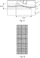
- FIG. 11 shows schematically a cross section of a tissue slide assembly, with a projection of a 2D detector array shown and serves to help explain the system setup.
- the tilted detector makes an image of an oblique cross section 5 of the tissue slide assembly.
- the tilt is in a scanning direction 6 , in the lateral direction (X′).
- the detector along the X axis the detector as Nx pixels and samples the object in the scan (lateral) direction X′ with ⁇ x′ per pixel and in the axial (vertical) direction 7 (Z) parallel to the optical axis O with ⁇ z per pixel.
- each pixel has a length L.
- the detector is tilted by an angle ⁇ ′, therefore the lateral and axial sampling at the object is given by:
- M is the magnification and n is the refractive index of the object.
- FIG. 12 shows schematically an example 2D detector array, that acquires data used to generate the image with an enhanced depth of focus.
- the pixels shown in white are sensitive to light and can be used for signal acquisition if activated, with other pixels not shown being used for dark current and signal offsets.
- a number of pixels, not shown, represent the pixel electronics.
- a number of rows (or lines) of pixels form an individual line imaging detector, which with reference to FIG. 10 is at one X′, Z coordinate and extends into the page along the Y axis.
- a strip of pixels consisting of adjacent lines of pixels can be combined using time delay integration (TDI) into a single line of pixel values.
- TDI time delay integration
- each strip of pixels can act as an individual TDI sensor, thereby improving signal-to-noise.
- each line imaging detector has a length of several thousand pixels extending in the Y direction, which for example represents line I as shown in FIG. 10 .
- the length can be 1000, 2000, 3000, 4000, 5000 or other numbers of pixels. If a focus actuator is not used to move the objective lens during lateral scan, then each line detector will image the sample at a constant depth over the depth of focus of the microscope scanner, which is approximately 1 ⁇ m.
- each strip of pixels can represent a number of rows of a single TDI block if the TDI is activated.
- the detector contains a number of these blocks, separated by readout electronics. For, example the detector can contain 100, 200, or 300 blocks. The detector can have other numbers of blocks. Relating to cross-section 5 , which is the projection of the detector in the sample, the distance in the z direction between each TDI block can be calculated using the above equation. Therefore, with a depth of focus of approximately 1 ⁇ m there can be a number of TDI blocks distributed within this depth of focus.
- the detector can be configured such that the distance in the z direction between blocks can be varied, and the distance can vary between blocks.
- One of these TDI blocks can be used individually or some together to provide image data at a particular depth. Then, one or more TDI blocks at a different position of the detector, along the X axis, can be activated to acquire image data for a different depth of the sample over a depth of focus. The second depth is separated from the first depth by at least the depth of focus (approximately 1 ⁇ m). Each TDI block, or TDI blocks, over the depth of focus at a particular depth in effect sweeps out a layer of image data within the sample, the layer having a thickness approximately equal to the depth of focus of the microscope ( ⁇ 1 ⁇ m).
- TDI blocks at different positions along the detector, each at a different depth and lateral position but having the same depth along its length, can be used to acquire the image data from the sample.
- the features to be imaged can lie anywhere within this 8 ⁇ m depth. Therefore, as cross-section 5 is swept laterally through the sample, each of these eight TDI blocks will acquire image data at the same X′, Y coordinates of the sample, but at different depths Z. It is therefore to be noted that active TDI blocks used to acquire data can be spaced from another active TDI block that is acquiring data by a number of TDI blocks that are not acquiring data.
- a first image comprising image data from these 8 TDI blocks is used to form a working image comprising image data for each X′, Y position imaged.
- image data will be acquired for the majority of the X′, Y positions already imaged, but at a different depths for those X′, Y positions.
- the working image is updated such that it contains the best focus image at that X′, Y position acquired thus far. This can be done on the fly, without the need to save all the image data, rather a working image file is saved and compared with the image file just acquired and updated where necessary.
- a synthetic 2D image is thereby generated with an enhanced depth of field, where a feature at one depth in the sample can be in focus and a different feature at a different depth in the sample can also be in focus, where those depths are greater than the depth of focus of the system such that it is not possible to have both in focus in a regular setup (which only acquires data at one depth over a depth of focus of the system).
- multiple pathological features can be in focus while these features change differently in depth within the sample.
- a weighted sum of the new image data with the existing working image data can be used to provide an updated working image.
- the detector is working in a line imaging mode, it should be noted that individual sections along the line image are used separately. This is because, a particular feature at one point along the line image can be in focus whilst another feature, due to it being at different depth outside the depth of focus, at another point along the line image can be out of focus. Therefore, selection is made on a more local (pixel) level, where pixel can mean several pixels sufficient to make a comparison with the working image data to determine which data at that lateral position (specific X′, Y coordinate range) is in the best focus.
- the TDI blocks used to acquire data can move up and down the detector, and also move relative to one another.
- the spacing between the TDI blocks used to acquire data can remain the same as the TDI blocks move, or the spacing between the TDI blocks can vary as a TDI blocks move, with the spacing between adjacent TDI blocks varying differently for different TDI blocks.
- This provides the ability to scan a sample at different resolution levels, and to have different resolution levels throughout the sample. For example, across a sample, features to be images could be predominantly in the top part of the sample and also in the bottom part of the sample. Then, a number of TDI blocks could be arranged to scan the top part of the sample and a number arranged to scan the bottom part of the sample, with few TDI blocks scanning the centre part of the sample.
- FIG. 13 shows schematically an example of oversampling, where an image with enhanced depth of field is to be acquired for the central clear region.
- FIG. 14 shows schematically a number of imaged regions or layers.
- each layer corresponds to what each TDI block (or blocks) images at a particular depth over the depth of focus of the microscope.
- the tissue slide assembly may be misaligned, or the sample to be imaged may vary significantly over the depth direction. Therefore, prior to acquiring imagery to be used in generating a synthetic 2-D image with an enhanced depth of field of a biological sample, a relatively low resolution image of the tissue slide assembly is obtained. This is used to estimate the z-position (depth) of the tissue volume. In other words, at one or more locations (X′, Y) the optimal focus (Z) is determined.
- the objective lens is moved appropriately along the optical axis O (or sample moved along the optical axis) and multiple TDIs are activated for acquisition of the data discussed above.
- the positions of the TDIs are moved up and down the detector as required.
- the section 5 can scan at a constant depth, but different parts of the detector can acquire data.
- a self focusing (autofocusing) sensor can be utilised as described for example in WO2011/161594A1. In such autofocusing configuration, the detector as shown in FIG.
- the enhanced image is generated without all of the separate images having to be saved, rather only a working image is saved and compared to the image just acquired thereby enabling an image with enhanced depth of field to be generated on the fly, without a large image buffer being required.
- the system can generate an image on the fly that can have multiple pathological features in focus, while those features are at different depths within the sample.
- FIG. 15 shows schematically an example of a system for generating a synthetic 2D image with an enhanced depth of field of a biological sample.
- the stages can move the sample horizontally and vertically.
- the low resolution camera LRCAM acquires the prior scan to determine the approximate position of the sample to be imaged across the tissue slide assembly.
- HRCAM is a camera, containing the tilted sensor as discussed.
- the objective lens (HROBJ) can be moved in the depth direction by the focus actuator (HRFOCACT).
- the global function of the microscope scanner is therefore as follows: A slide is put on the scanner's stage (STAGE), then the low-resolution camera (LRCAM) makes an image of the slide before scanning the tissue on the slide in a high resolution.
- This LR-image is used to, among other things, derive the region(s) of interest, i.e. to find the area(s) on the slide that needs to be scanned.
- Each region of interest is scanned by means of performing one or more scan passes with the high-resolution camera (HRCAM).
- the focus distance is measured via the HRCAM and controlled automatically via the focus actuator (HRFOCACT).
- HR-image is transferred from the scanner to a destination (e.g. IMS) via the Ethernet interface (GbE).
- Focus stacking was briefly introduced with reference to FIG. 5 .
- FIG. 16 an example workflow for focus staking used in generating a synthetic image with enhanced depth of field is shown.
- focus stacking is described with respect to a system acquiring data as shown in FIG. 8 , however it has applicability for a tilted detector that provides an oblique cross section.
- a layer as discussed previously, relates to what the microscope scanner is imaging at a particular depth in a sample over a depth of focus at that depth.
- the explanation relates to a non-tilted detector the layer is at the same depth within the sample, but as discussed this focus stacking process equally applies to a tilted detector and oblique cross section over which data is acquired.
- the image of layer n is acquired. Firstly, the amount of energy of the input image, acquired at z-position n, is determined. The amount of energy is determined by applying a high-pass filter (i.e. a Laplacian filter), followed by a smoothing operation (to reduce the amount of noise). Secondly, this calculated amount of energy of layer n is compared with the energy of layer ⁇ (n ⁇ 1). For every individual pixel, it is determined if the current layer (i.e. image data of layer n), or the combined result (i.e. combined image data of layer ⁇ (n ⁇ 1)—the working image as discussed previously) should be used; the result of this is the “Layer selection” of FIG. 16 .
- a high-pass filter i.e. a Laplacian filter
- a tilted sensor is combined with focus stacking, in streaming mode. Then, it is no longer needed to store the intermediate results completely (i.e. image data of layer ⁇ (n ⁇ 1) and energy of layer ⁇ (n ⁇ 1)), but only a limited history of the image and energy data is needed, determined by the footprint of the used image filters (i.e. high-pass filter and smoothing filter).
- the energy per row i.e. per z-position
- the slanted image is in a plane in Y (rows of the image) and X′/Z (columns of the image).
- FIGS. 17 and 18 show the final result, the image with an enhanced depth of field, which is the right hand image.
- the left hand image is a single image at one depth, as would be acquired by a conventional microscope.
- In the right hand image more features, cells, are in focus as compared to that acquired conventionally.
- the optimal image layer is determined by the amount of energy (i.e. a high-pass filter).
- the different colour channels are merged (i.e. using a RGB2Y operation), before determining the high frequency information.
- pathological information i.e. from an external source like the LIS/HIS or determined by image analysis
- the optimal layer can locally be determined by the amount of energy using one (or multiple) specific colour stain(s) (e.g. focussing on the chromatin pattern of the nuclei).
- adding a colour separation step can result in the use of different 2D smoothing kernels. For example, nuclei contain much smaller details than the cytoplasm and therefore benefits from smaller smoothing kernels ( ⁇ 2).
- the acquired data can be translated to the wavelet domain, where the high frequency sub band can be used as a representation of the energy.
- This can be combined with the iSyntax compression (see for example U.S. Pat. No. 6,711,297B1 and U.S. Pat. No. 6,553,141).
- the conversion to a single image layer having enhanced depth of field is applied before sending the image to the server. It is also possible that the conversion to a single layer is performed on the server, such that output of the sensor is directly transferred to the server.
- the pixel values of multiple layers are combined using a particular weighting, based on the distribution of the energy of the pixels.
- This method can also be used to measure the thickness of the tissue, as this is related to the energy of each layer.
- a computer program or computer program element is provided that is characterized by being configured to execute the method steps of the method according to one of the preceding embodiments, on an appropriate system.
- the computer program element might therefore be stored on a computer unit, which might also be part of an embodiment.
- This computing unit may be configured to perform or induce performing of the steps of the method described above. Moreover, it may be configured to operate the components of the above described apparatus.
- the computing unit can be configured to operate automatically and/or to execute the orders of a user.
- a computer program may be loaded into a working memory of a data processor.
- the data processor may thus be equipped to carry out the method according to one of the preceding embodiments.
- This exemplary embodiment of the invention covers both, a computer program that right from the beginning uses the invention and computer program that by means of an update turns an existing program into a program that uses the invention.
- the computer program element might be able to provide all necessary steps to fulfill the procedure of an exemplary embodiment of the method as described above.
- a computer readable medium such as a CD-ROM
- the computer readable medium has a computer program element stored on it which computer program element is described by the preceding section.
- a computer program may be stored and/or distributed on a suitable medium, such as an optical storage medium or a solid state medium supplied together with or as part of other hardware, but may also be distributed in other forms, such as via the internet or other wired or wireless telecommunication systems.
- a suitable medium such as an optical storage medium or a solid state medium supplied together with or as part of other hardware, but may also be distributed in other forms, such as via the internet or other wired or wireless telecommunication systems.
- the computer program may also be presented over a network like the World Wide Web and can be downloaded into the working memory of a data processor from such a network.
- a medium for making a computer program element available for downloading is provided, which computer program element is arranged to perform a method according to one of the previously described embodiments of the invention.
Abstract
Description
-
- a microscope-scanner; and
- a processing unit.
e) generating first working image data for the first lateral position, the generation comprising processing the first image data and the third image data by a focus stacking algorithm; and
f) generating second working image data for the second lateral position, the generation comprising processing the second image data and the fourth image data by the focus stacking algorithm; and
l) combining the first working image data and the second working image data, during acquisition of image data, to generate the synthetic 2D image with an enhanced depth of field of the biological sample.
h) generating a second working energy data as the second energy data if the second image data is selected as the second working image or generating the second working energy data as the fourth energy data if the fourth image data is selected as the second working image is the fourth image data.
j) generating new first working image data for the first lateral position, the generation comprising processing the fifth image data and the first working image data by the focus stacking algorithm, wherein the new first working image data becomes the first working image data; and
k) generating new second working image data for the second lateral position, the generation comprising processing the sixth image data and the second working image data by the focus stacking algorithm, wherein the new second working image data becomes the second working image data.
Claims (18)
Applications Claiming Priority (4)
| Application Number | Priority Date | Filing Date | Title |
|---|---|---|---|
| EP16156763.1 | 2016-02-22 | ||
| EP16156763 | 2016-02-22 | ||
| EP16156763 | 2016-02-22 | ||
| PCT/EP2017/053965 WO2017144482A1 (en) | 2016-02-22 | 2017-02-22 | System for generating a synthetic 2d image with an enhanced depth of field of a biological sample |
Publications (2)
| Publication Number | Publication Date |
|---|---|
| US20190075247A1 US20190075247A1 (en) | 2019-03-07 |
| US10623627B2 true US10623627B2 (en) | 2020-04-14 |
Family
ID=55588029
Family Applications (1)
| Application Number | Title | Priority Date | Filing Date |
|---|---|---|---|
| US16/078,046 Active US10623627B2 (en) | 2016-02-22 | 2017-02-22 | System for generating a synthetic 2D image with an enhanced depth of field of a biological sample |
Country Status (6)
| Country | Link |
|---|---|
| US (1) | US10623627B2 (en) |
| EP (1) | EP3420393B1 (en) |
| JP (2) | JP7239324B2 (en) |
| CN (1) | CN108700733A (en) |
| RU (1) | RU2734447C2 (en) |
| WO (1) | WO2017144482A1 (en) |
Families Citing this family (9)
| Publication number | Priority date | Publication date | Assignee | Title |
|---|---|---|---|---|
| DE112015006271T5 (en) * | 2015-04-16 | 2018-01-18 | Olympus Corporation | Microscopy system, microscopy method and microscopy program |
| US11112592B2 (en) * | 2015-04-24 | 2021-09-07 | Board Of Supervisors Of Louisiana State University And Agricultural And Mechanical College | Fine focus microscope control |
| WO2018152071A1 (en) * | 2017-02-15 | 2018-08-23 | Flir Systems, Inc. | Systems and methods for efficient enhanced image filtering by collaborative sharpening in similarity domain |
| US10502941B2 (en) * | 2017-09-29 | 2019-12-10 | Leica Biosystmes Imaging, Inc. | Two-dimensional and three-dimensional fixed Z scanning |
| US20190149795A1 (en) * | 2017-11-14 | 2019-05-16 | Stereo Display, Inc. | Three dimensional imaging using line scan camera |
| JP7169092B2 (en) * | 2018-05-21 | 2022-11-10 | 株式会社ミツトヨ | VARIABLE FOCAL LENGTH LENS DEVICE AND VARIABLE FOCAL LENGTH LENS CONTROL METHOD |
| JP7098474B2 (en) * | 2018-08-07 | 2022-07-11 | 株式会社ミツトヨ | Non-contact displacement meter |
| WO2021100328A1 (en) * | 2019-11-22 | 2021-05-27 | ソニーグループ株式会社 | Image processing method, image processing device, and image processing system |
| WO2024072756A1 (en) * | 2022-09-28 | 2024-04-04 | Illumina, Inc. | Auto-focus using spot-measurement |
Citations (23)
| Publication number | Priority date | Publication date | Assignee | Title |
|---|---|---|---|---|
| US4141032A (en) | 1976-12-08 | 1979-02-20 | Ernst Leitz Wetzlar Gmbh | Method of and apparatus for the expansion of the range of the depth of focus beyond the limit given by conventional images |
| US6553141B1 (en) | 2000-01-21 | 2003-04-22 | Stentor, Inc. | Methods and apparatus for compression of transform data |
| US20030184730A1 (en) * | 2002-01-23 | 2003-10-02 | The Regents Of The University Of California | Fast 3D cytometry for information in tissue engineering |
| US20030222197A1 (en) * | 2002-03-13 | 2003-12-04 | Reese Steven A. | Multi-axis integration system and method |
| US6711297B1 (en) | 1998-07-03 | 2004-03-23 | University Of Pittsburgh - Of The Commonwealth System Of Higher Education | Methods and apparatus for dynamic transfer of image data |
| US20050089208A1 (en) | 2003-07-22 | 2005-04-28 | Rui-Tao Dong | System and method for generating digital images of a microscope slide |
| US20090221920A1 (en) * | 2008-01-18 | 2009-09-03 | Boppart Stephen A | Low-coherence interferometry and optical coherence tomography for image-guided surgical treatment of solid tumors |
| US20090231689A1 (en) | 2007-05-04 | 2009-09-17 | Aperio Technologies, Inc. | Rapid Microscope Scanner for Volume Image Acquisition |
| WO2009120718A1 (en) | 2008-03-24 | 2009-10-01 | The Trustees Of Columbia University In The City Of New York | Methods, systems, and media for controlling depth of field in images |
| US20090295963A1 (en) | 2006-02-10 | 2009-12-03 | Pascal Bamford | Method and apparatus and computer program product for collecting digital image data from microscope media-based specimens |
| US20110090327A1 (en) * | 2009-10-15 | 2011-04-21 | General Electric Company | System and method for imaging with enhanced depth of field |
| US20110157349A1 (en) | 2009-12-25 | 2011-06-30 | Sony Corporation | Stage control device, stage control method, stage control program, and microscope |
| WO2011080670A1 (en) | 2009-12-30 | 2011-07-07 | Koninklijke Philips Electronics N.V. | Sensor for microscopy. |
| WO2011161594A1 (en) | 2010-06-24 | 2011-12-29 | Koninklijke Philips Electronics N.V. | Autofocus based on differential measurements |
| US20120176489A1 (en) | 2009-09-11 | 2012-07-12 | Hamamatsu Photonics K.K. | Image-acquisition device |
| US20130016885A1 (en) | 2011-07-14 | 2013-01-17 | Canon Kabushiki Kaisha | Image processing apparatus, imaging system, and image processing system |
| WO2013008121A1 (en) | 2011-07-13 | 2013-01-17 | Koninklijke Philips Electronics N.V. | Method for automatically adjusting a focal plane of a digital pathology image |
| WO2013040686A1 (en) | 2011-09-21 | 2013-03-28 | Huron Technologies International Inc. | Slide scanner with a tilted image plane |
| US20140125776A1 (en) | 2011-05-25 | 2014-05-08 | Huron Technologies International Inc, | 3d pathology slide scanner |
| US20140293117A1 (en) | 2011-12-02 | 2014-10-02 | Canon Kabushiki Kaisha | Image processing apparatus and image processing method |
| US20140347628A1 (en) * | 2011-10-20 | 2014-11-27 | Asociacion Industrial De Optica, Color E Imagen - Aido | Multi-view fundus camera |
| US20150309299A1 (en) | 2013-01-09 | 2015-10-29 | Olympus Corporation | Imaging apparatus, microscope system, and imaging method |
| US20150377777A1 (en) * | 2014-06-29 | 2015-12-31 | OPTICS 3D Ltd. | Dual structured illumination modulated in phase and intensity |
Family Cites Families (15)
| Publication number | Priority date | Publication date | Assignee | Title |
|---|---|---|---|---|
| US5448399A (en) * | 1992-03-13 | 1995-09-05 | Park Scientific Instruments | Optical system for scanning microscope |
| JP2000056789A (en) * | 1998-06-02 | 2000-02-25 | Sanyo Electric Co Ltd | Speech synthesis device and telephone set |
| US6711283B1 (en) * | 2000-05-03 | 2004-03-23 | Aperio Technologies, Inc. | Fully automatic rapid microscope slide scanner |
| US20030022219A1 (en) * | 2001-07-13 | 2003-01-30 | Millennium Pharmaceuticals, Inc. | 85080, a human metal ion transporter family member and uses thereof |
| GB0406730D0 (en) * | 2004-03-25 | 2004-04-28 | 1 Ltd | Focussing method |
| GB0717849D0 (en) * | 2007-09-13 | 2007-10-24 | Vibraglaz Uk Ltd | Finishing medium and process |
| JP5212122B2 (en) * | 2009-01-09 | 2013-06-19 | ソニー株式会社 | Biological sample image acquisition apparatus, biological sample image acquisition method, and program |
| AU2009230797B2 (en) * | 2009-10-28 | 2011-06-09 | Canon Kabushiki Kaisha | Focus finding and alignment using a split linear mask |
| JP5543863B2 (en) * | 2010-07-07 | 2014-07-09 | オリンパス株式会社 | Imaging device |
| US20120098947A1 (en) * | 2010-10-20 | 2012-04-26 | David Robert Wilkes | Producing universally sharp images |
| CN102663721B (en) * | 2012-04-01 | 2015-04-15 | 清华大学 | Defocus depth estimation and full focus image acquisition method of dynamic scene |
| JP2014029460A (en) * | 2012-07-05 | 2014-02-13 | Canon Inc | Microscope device, and control method therefor |
| JP2014022987A (en) * | 2012-07-19 | 2014-02-03 | Canon Inc | Semiconductor element, microscope device, and control method for microscope device |
| CN102937599B (en) * | 2012-10-25 | 2015-01-07 | 中国科学院自动化研究所 | Non-destructive testing systems and method used for detecting a metal-containing object through X-ray detection |
| JP6246555B2 (en) * | 2013-10-25 | 2017-12-13 | 株式会社キーエンス | Microscope imaging apparatus, microscope imaging method, and microscope imaging program |
-
2017
- 2017-02-22 WO PCT/EP2017/053965 patent/WO2017144482A1/en active Application Filing
- 2017-02-22 EP EP17705911.0A patent/EP3420393B1/en active Active
- 2017-02-22 JP JP2018544146A patent/JP7239324B2/en active Active
- 2017-02-22 US US16/078,046 patent/US10623627B2/en active Active
- 2017-02-22 RU RU2018133474A patent/RU2734447C2/en active
- 2017-02-22 CN CN201780012672.6A patent/CN108700733A/en active Pending
-
2020
- 2020-12-28 JP JP2020218563A patent/JP7252190B2/en active Active
Patent Citations (25)
| Publication number | Priority date | Publication date | Assignee | Title |
|---|---|---|---|---|
| US4141032A (en) | 1976-12-08 | 1979-02-20 | Ernst Leitz Wetzlar Gmbh | Method of and apparatus for the expansion of the range of the depth of focus beyond the limit given by conventional images |
| US6711297B1 (en) | 1998-07-03 | 2004-03-23 | University Of Pittsburgh - Of The Commonwealth System Of Higher Education | Methods and apparatus for dynamic transfer of image data |
| US6553141B1 (en) | 2000-01-21 | 2003-04-22 | Stentor, Inc. | Methods and apparatus for compression of transform data |
| US20030184730A1 (en) * | 2002-01-23 | 2003-10-02 | The Regents Of The University Of California | Fast 3D cytometry for information in tissue engineering |
| US20030222197A1 (en) * | 2002-03-13 | 2003-12-04 | Reese Steven A. | Multi-axis integration system and method |
| US20050089208A1 (en) | 2003-07-22 | 2005-04-28 | Rui-Tao Dong | System and method for generating digital images of a microscope slide |
| US20090295963A1 (en) | 2006-02-10 | 2009-12-03 | Pascal Bamford | Method and apparatus and computer program product for collecting digital image data from microscope media-based specimens |
| US20090231689A1 (en) | 2007-05-04 | 2009-09-17 | Aperio Technologies, Inc. | Rapid Microscope Scanner for Volume Image Acquisition |
| US20090221920A1 (en) * | 2008-01-18 | 2009-09-03 | Boppart Stephen A | Low-coherence interferometry and optical coherence tomography for image-guided surgical treatment of solid tumors |
| WO2009120718A1 (en) | 2008-03-24 | 2009-10-01 | The Trustees Of Columbia University In The City Of New York | Methods, systems, and media for controlling depth of field in images |
| US20120176489A1 (en) | 2009-09-11 | 2012-07-12 | Hamamatsu Photonics K.K. | Image-acquisition device |
| US20110090327A1 (en) * | 2009-10-15 | 2011-04-21 | General Electric Company | System and method for imaging with enhanced depth of field |
| US20110157349A1 (en) | 2009-12-25 | 2011-06-30 | Sony Corporation | Stage control device, stage control method, stage control program, and microscope |
| WO2011080670A1 (en) | 2009-12-30 | 2011-07-07 | Koninklijke Philips Electronics N.V. | Sensor for microscopy. |
| US20120287256A1 (en) | 2009-12-30 | 2012-11-15 | Koninklijke Philips Electronics N.V. | Sensor for microscopy |
| WO2011161594A1 (en) | 2010-06-24 | 2011-12-29 | Koninklijke Philips Electronics N.V. | Autofocus based on differential measurements |
| US20140125776A1 (en) | 2011-05-25 | 2014-05-08 | Huron Technologies International Inc, | 3d pathology slide scanner |
| WO2013008121A1 (en) | 2011-07-13 | 2013-01-17 | Koninklijke Philips Electronics N.V. | Method for automatically adjusting a focal plane of a digital pathology image |
| US9373168B2 (en) | 2011-07-13 | 2016-06-21 | Koninklijke Philips N.V. | Method for automatically adjusting a focal plane of a digital pathology image |
| US20130016885A1 (en) | 2011-07-14 | 2013-01-17 | Canon Kabushiki Kaisha | Image processing apparatus, imaging system, and image processing system |
| WO2013040686A1 (en) | 2011-09-21 | 2013-03-28 | Huron Technologies International Inc. | Slide scanner with a tilted image plane |
| US20140347628A1 (en) * | 2011-10-20 | 2014-11-27 | Asociacion Industrial De Optica, Color E Imagen - Aido | Multi-view fundus camera |
| US20140293117A1 (en) | 2011-12-02 | 2014-10-02 | Canon Kabushiki Kaisha | Image processing apparatus and image processing method |
| US20150309299A1 (en) | 2013-01-09 | 2015-10-29 | Olympus Corporation | Imaging apparatus, microscope system, and imaging method |
| US20150377777A1 (en) * | 2014-06-29 | 2015-12-31 | OPTICS 3D Ltd. | Dual structured illumination modulated in phase and intensity |
Non-Patent Citations (5)
| Title |
|---|
| "All Focused Image by Focal Stacking", roman10, Apr. 12, 2011 http://www.roman10.net/all-focused-image-by-focal-stacking/. |
| Boyde, A. et al., "Improved Digital Sem of Cancellous Bone: Scanning Direction of Detection, Through Focus for In-Focus and Sample Orientation", J Anat. Feb. 2003; 202(2): 183-194. http://www.ncbi.nlm.nih.gov/pmc/articles/PMC1571076/. |
| Focus Stalking, Wikipedia https://en.wikipedia.org/wiki/Focus_stacking, downloaded from the Internet Aug. 15, 2018. |
| Observations on the PCT International Search Report and the Written Opinion of International Application No. PCT/EP2017/053965, dated Mar. 7, 2018. |
| PCT International Search Report, International application No. PCT/EP2017/053965, dated Apr. 28, 2017. |
Also Published As
| Publication number | Publication date |
|---|---|
| RU2018133474A (en) | 2020-03-24 |
| JP2019507384A (en) | 2019-03-14 |
| EP3420393B1 (en) | 2024-04-10 |
| RU2018133474A3 (en) | 2020-05-15 |
| JP2021073489A (en) | 2021-05-13 |
| JP7239324B2 (en) | 2023-03-14 |
| US20190075247A1 (en) | 2019-03-07 |
| RU2734447C2 (en) | 2020-10-16 |
| WO2017144482A1 (en) | 2017-08-31 |
| CN108700733A (en) | 2018-10-23 |
| JP7252190B2 (en) | 2023-04-04 |
| EP3420393A1 (en) | 2019-01-02 |
Similar Documents
| Publication | Publication Date | Title |
|---|---|---|
| US10623627B2 (en) | System for generating a synthetic 2D image with an enhanced depth of field of a biological sample | |
| JP4806630B2 (en) | A method for acquiring optical image data of three-dimensional objects using multi-axis integration | |
| US9088729B2 (en) | Imaging apparatus and method of controlling same | |
| US7723662B2 (en) | Microscopy arrangements and approaches | |
| US9426363B2 (en) | Image forming apparatus image forming method and image sensor | |
| US20190268573A1 (en) | Digital microscope apparatus for reimaging blurry portion based on edge detection | |
| US10921575B2 (en) | Auto-focus methods and systems for digital imaging using multi-spectral trajectories | |
| EP2786340A1 (en) | Image processing apparatus and image processing method | |
| JP5374119B2 (en) | Distance information acquisition device, imaging device, and program | |
| WO2018138098A1 (en) | Micro-spectrometry measurement method and system | |
| US20190052793A1 (en) | Apparatus for generating a synthetic 2d image with an enhanced depth of field of an object | |
| KR20140045331A (en) | Fast auto-focus in microscopic imaging | |
| CN109883391B (en) | Monocular distance measurement method based on digital imaging of microlens array | |
| JP2013531268A (en) | Measuring distance using coded aperture | |
| JP7064796B2 (en) | Image reconstruction method, device and microimaging device | |
| CN114424102A (en) | Image processing apparatus and method for use in an autofocus system | |
| US20230085827A1 (en) | Single-shot autofocusing of microscopy images using deep learning | |
| JP2015108837A (en) | Image processing apparatus and image processing method | |
| CN105651699B (en) | It is a kind of based on the dynamic of area array cameras with burnt method | |
| CN110349237A (en) | Quick body imaging method based on convolutional neural networks | |
| CN111656163A (en) | Method and apparatus for extending depth of field during fluorescence microscopy imaging | |
| CN113933984A (en) | Method and microscope for generating an image composed of a plurality of microscope subimages | |
| JP2017083790A (en) | Image acquisition device and image acquisition method using the same | |
| CN115060367A (en) | Full-glass data cube acquisition method based on microscopic hyperspectral imaging platform | |
| KR20230073005A (en) | Device and method for generating whole slide image having z axis scanning |
Legal Events
| Date | Code | Title | Description |
|---|---|---|---|
| FEPP | Fee payment procedure |
Free format text: ENTITY STATUS SET TO UNDISCOUNTED (ORIGINAL EVENT CODE: BIG.); ENTITY STATUS OF PATENT OWNER: LARGE ENTITY |
|
| STPP | Information on status: patent application and granting procedure in general |
Free format text: DOCKETED NEW CASE - READY FOR EXAMINATION |
|
| STPP | Information on status: patent application and granting procedure in general |
Free format text: NON FINAL ACTION MAILED |
|
| STPP | Information on status: patent application and granting procedure in general |
Free format text: RESPONSE TO NON-FINAL OFFICE ACTION ENTERED AND FORWARDED TO EXAMINER |
|
| STPP | Information on status: patent application and granting procedure in general |
Free format text: NOTICE OF ALLOWANCE MAILED -- APPLICATION RECEIVED IN OFFICE OF PUBLICATIONS |
|
| AS | Assignment |
Owner name: KONINKLIJKE PHILIPS N.V., NETHERLANDS Free format text: ASSIGNMENT OF ASSIGNORS INTEREST;ASSIGNORS:VINK, JELTE PETER;HULSKEN, BAS;WOLTERS, MARTIJN;AND OTHERS;SIGNING DATES FROM 20180129 TO 20200310;REEL/FRAME:052068/0211 |
|
| STCF | Information on status: patent grant |
Free format text: PATENTED CASE |
|
| MAFP | Maintenance fee payment |
Free format text: PAYMENT OF MAINTENANCE FEE, 4TH YEAR, LARGE ENTITY (ORIGINAL EVENT CODE: M1551); ENTITY STATUS OF PATENT OWNER: LARGE ENTITY Year of fee payment: 4 |