JP6189862B2 - 電力装置における制御された共振 - Google Patents
電力装置における制御された共振 Download PDFInfo
- Publication number
- JP6189862B2 JP6189862B2 JP2014551366A JP2014551366A JP6189862B2 JP 6189862 B2 JP6189862 B2 JP 6189862B2 JP 2014551366 A JP2014551366 A JP 2014551366A JP 2014551366 A JP2014551366 A JP 2014551366A JP 6189862 B2 JP6189862 B2 JP 6189862B2
- Authority
- JP
- Japan
- Prior art keywords
- signal
- resonance
- control system
- programmed
- input
- Prior art date
- Legal status (The legal status is an assumption and is not a legal conclusion. Google has not performed a legal analysis and makes no representation as to the accuracy of the status listed.)
- Active
Links
- 239000013598 vector Substances 0.000 claims description 38
- 230000000737 periodic effect Effects 0.000 claims description 14
- 239000003990 capacitor Substances 0.000 claims description 12
- 230000006698 induction Effects 0.000 claims description 12
- 230000001939 inductive effect Effects 0.000 claims description 12
- 230000003321 amplification Effects 0.000 claims description 5
- 238000003199 nucleic acid amplification method Methods 0.000 claims description 5
- 238000013178 mathematical model Methods 0.000 claims description 3
- 230000036961 partial effect Effects 0.000 claims description 3
- 238000004146 energy storage Methods 0.000 claims description 2
- 238000000034 method Methods 0.000 description 46
- 230000003287 optical effect Effects 0.000 description 41
- 238000012545 processing Methods 0.000 description 39
- 238000006243 chemical reaction Methods 0.000 description 35
- 230000006870 function Effects 0.000 description 26
- 238000010586 diagram Methods 0.000 description 21
- 230000008859 change Effects 0.000 description 12
- 230000005611 electricity Effects 0.000 description 10
- 238000007726 management method Methods 0.000 description 10
- 230000008569 process Effects 0.000 description 10
- 238000013459 approach Methods 0.000 description 9
- 230000004907 flux Effects 0.000 description 9
- 238000005516 engineering process Methods 0.000 description 8
- 238000004804 winding Methods 0.000 description 8
- 230000003068 static effect Effects 0.000 description 7
- 210000004027 cell Anatomy 0.000 description 6
- 238000013461 design Methods 0.000 description 6
- 230000001276 controlling effect Effects 0.000 description 5
- 230000001965 increasing effect Effects 0.000 description 5
- 239000000203 mixture Substances 0.000 description 5
- 230000010355 oscillation Effects 0.000 description 5
- 230000009471 action Effects 0.000 description 4
- 230000005693 optoelectronics Effects 0.000 description 4
- 230000005855 radiation Effects 0.000 description 4
- 230000002441 reversible effect Effects 0.000 description 4
- 230000008901 benefit Effects 0.000 description 3
- 238000004364 calculation method Methods 0.000 description 3
- 230000000694 effects Effects 0.000 description 3
- 230000006872 improvement Effects 0.000 description 3
- 230000000670 limiting effect Effects 0.000 description 3
- 230000005389 magnetism Effects 0.000 description 3
- 230000005355 Hall effect Effects 0.000 description 2
- 238000012733 comparative method Methods 0.000 description 2
- 230000000295 complement effect Effects 0.000 description 2
- 239000012141 concentrate Substances 0.000 description 2
- 238000012937 correction Methods 0.000 description 2
- 238000001514 detection method Methods 0.000 description 2
- 238000011161 development Methods 0.000 description 2
- 230000002452 interceptive effect Effects 0.000 description 2
- 238000013507 mapping Methods 0.000 description 2
- 239000011159 matrix material Substances 0.000 description 2
- 230000005055 memory storage Effects 0.000 description 2
- 230000002829 reductive effect Effects 0.000 description 2
- 230000001360 synchronised effect Effects 0.000 description 2
- 238000012546 transfer Methods 0.000 description 2
- 238000004458 analytical method Methods 0.000 description 1
- 230000009286 beneficial effect Effects 0.000 description 1
- 230000002457 bidirectional effect Effects 0.000 description 1
- 230000033228 biological regulation Effects 0.000 description 1
- 230000015572 biosynthetic process Effects 0.000 description 1
- 230000003139 buffering effect Effects 0.000 description 1
- 210000003850 cellular structure Anatomy 0.000 description 1
- 238000013500 data storage Methods 0.000 description 1
- 230000003247 decreasing effect Effects 0.000 description 1
- 230000001419 dependent effect Effects 0.000 description 1
- 230000005684 electric field Effects 0.000 description 1
- 238000005868 electrolysis reaction Methods 0.000 description 1
- 230000005672 electromagnetic field Effects 0.000 description 1
- 230000005284 excitation Effects 0.000 description 1
- 238000000605 extraction Methods 0.000 description 1
- 239000012530 fluid Substances 0.000 description 1
- 230000014509 gene expression Effects 0.000 description 1
- 238000010438 heat treatment Methods 0.000 description 1
- 230000010354 integration Effects 0.000 description 1
- 230000004048 modification Effects 0.000 description 1
- 238000012986 modification Methods 0.000 description 1
- 230000010363 phase shift Effects 0.000 description 1
- 230000009467 reduction Effects 0.000 description 1
- 230000001105 regulatory effect Effects 0.000 description 1
- 230000004044 response Effects 0.000 description 1
- 239000000523 sample Substances 0.000 description 1
- 238000001228 spectrum Methods 0.000 description 1
- 239000000758 substrate Substances 0.000 description 1
- 230000000153 supplemental effect Effects 0.000 description 1
- 238000010408 sweeping Methods 0.000 description 1
- 238000003786 synthesis reaction Methods 0.000 description 1
- 230000009466 transformation Effects 0.000 description 1
- 230000007704 transition Effects 0.000 description 1
Images


Classifications
-
- H—ELECTRICITY
- H02—GENERATION; CONVERSION OR DISTRIBUTION OF ELECTRIC POWER
- H02P—CONTROL OR REGULATION OF ELECTRIC MOTORS, ELECTRIC GENERATORS OR DYNAMO-ELECTRIC CONVERTERS; CONTROLLING TRANSFORMERS, REACTORS OR CHOKE COILS
- H02P23/00—Arrangements or methods for the control of AC motors characterised by a control method other than vector control
- H02P23/0077—Characterised by the use of a particular software algorithm
-
- H—ELECTRICITY
- H02—GENERATION; CONVERSION OR DISTRIBUTION OF ELECTRIC POWER
- H02M—APPARATUS FOR CONVERSION BETWEEN AC AND AC, BETWEEN AC AND DC, OR BETWEEN DC AND DC, AND FOR USE WITH MAINS OR SIMILAR POWER SUPPLY SYSTEMS; CONVERSION OF DC OR AC INPUT POWER INTO SURGE OUTPUT POWER; CONTROL OR REGULATION THEREOF
- H02M7/00—Conversion of ac power input into dc power output; Conversion of dc power input into ac power output
- H02M7/02—Conversion of ac power input into dc power output without possibility of reversal
- H02M7/04—Conversion of ac power input into dc power output without possibility of reversal by static converters
- H02M7/12—Conversion of ac power input into dc power output without possibility of reversal by static converters using discharge tubes with control electrode or semiconductor devices with control electrode
- H02M7/21—Conversion of ac power input into dc power output without possibility of reversal by static converters using discharge tubes with control electrode or semiconductor devices with control electrode using devices of a triode or transistor type requiring continuous application of a control signal
- H02M7/217—Conversion of ac power input into dc power output without possibility of reversal by static converters using discharge tubes with control electrode or semiconductor devices with control electrode using devices of a triode or transistor type requiring continuous application of a control signal using semiconductor devices only
-
- H—ELECTRICITY
- H02—GENERATION; CONVERSION OR DISTRIBUTION OF ELECTRIC POWER
- H02M—APPARATUS FOR CONVERSION BETWEEN AC AND AC, BETWEEN AC AND DC, OR BETWEEN DC AND DC, AND FOR USE WITH MAINS OR SIMILAR POWER SUPPLY SYSTEMS; CONVERSION OF DC OR AC INPUT POWER INTO SURGE OUTPUT POWER; CONTROL OR REGULATION THEREOF
- H02M7/00—Conversion of ac power input into dc power output; Conversion of dc power input into ac power output
- H02M7/42—Conversion of dc power input into ac power output without possibility of reversal
- H02M7/44—Conversion of dc power input into ac power output without possibility of reversal by static converters
- H02M7/48—Conversion of dc power input into ac power output without possibility of reversal by static converters using discharge tubes with control electrode or semiconductor devices with control electrode
- H02M7/53—Conversion of dc power input into ac power output without possibility of reversal by static converters using discharge tubes with control electrode or semiconductor devices with control electrode using devices of a triode or transistor type requiring continuous application of a control signal
- H02M7/537—Conversion of dc power input into ac power output without possibility of reversal by static converters using discharge tubes with control electrode or semiconductor devices with control electrode using devices of a triode or transistor type requiring continuous application of a control signal using semiconductor devices only, e.g. single switched pulse inverters
- H02M7/539—Conversion of dc power input into ac power output without possibility of reversal by static converters using discharge tubes with control electrode or semiconductor devices with control electrode using devices of a triode or transistor type requiring continuous application of a control signal using semiconductor devices only, e.g. single switched pulse inverters with automatic control of output wave form or frequency
-
- H—ELECTRICITY
- H02—GENERATION; CONVERSION OR DISTRIBUTION OF ELECTRIC POWER
- H02P—CONTROL OR REGULATION OF ELECTRIC MOTORS, ELECTRIC GENERATORS OR DYNAMO-ELECTRIC CONVERTERS; CONTROLLING TRANSFORMERS, REACTORS OR CHOKE COILS
- H02P23/00—Arrangements or methods for the control of AC motors characterised by a control method other than vector control
- H02P23/0004—Control strategies in general, e.g. linear type, e.g. P, PI, PID, using robust control
-
- H—ELECTRICITY
- H05—ELECTRIC TECHNIQUES NOT OTHERWISE PROVIDED FOR
- H05B—ELECTRIC HEATING; ELECTRIC LIGHT SOURCES NOT OTHERWISE PROVIDED FOR; CIRCUIT ARRANGEMENTS FOR ELECTRIC LIGHT SOURCES, IN GENERAL
- H05B3/00—Ohmic-resistance heating
-
- H—ELECTRICITY
- H05—ELECTRIC TECHNIQUES NOT OTHERWISE PROVIDED FOR
- H05B—ELECTRIC HEATING; ELECTRIC LIGHT SOURCES NOT OTHERWISE PROVIDED FOR; CIRCUIT ARRANGEMENTS FOR ELECTRIC LIGHT SOURCES, IN GENERAL
- H05B6/00—Heating by electric, magnetic or electromagnetic fields
- H05B6/02—Induction heating
-
- H—ELECTRICITY
- H02—GENERATION; CONVERSION OR DISTRIBUTION OF ELECTRIC POWER
- H02M—APPARATUS FOR CONVERSION BETWEEN AC AND AC, BETWEEN AC AND DC, OR BETWEEN DC AND DC, AND FOR USE WITH MAINS OR SIMILAR POWER SUPPLY SYSTEMS; CONVERSION OF DC OR AC INPUT POWER INTO SURGE OUTPUT POWER; CONTROL OR REGULATION THEREOF
- H02M7/00—Conversion of ac power input into dc power output; Conversion of dc power input into ac power output
- H02M7/42—Conversion of dc power input into ac power output without possibility of reversal
- H02M7/44—Conversion of dc power input into ac power output without possibility of reversal by static converters
- H02M7/48—Conversion of dc power input into ac power output without possibility of reversal by static converters using discharge tubes with control electrode or semiconductor devices with control electrode
- H02M7/4815—Resonant converters
- H02M7/4818—Resonant converters with means for adaptation of resonance frequency, e.g. by modification of capacitance or inductance of resonance circuits
-
- Y—GENERAL TAGGING OF NEW TECHNOLOGICAL DEVELOPMENTS; GENERAL TAGGING OF CROSS-SECTIONAL TECHNOLOGIES SPANNING OVER SEVERAL SECTIONS OF THE IPC; TECHNICAL SUBJECTS COVERED BY FORMER USPC CROSS-REFERENCE ART COLLECTIONS [XRACs] AND DIGESTS
- Y02—TECHNOLOGIES OR APPLICATIONS FOR MITIGATION OR ADAPTATION AGAINST CLIMATE CHANGE
- Y02B—CLIMATE CHANGE MITIGATION TECHNOLOGIES RELATED TO BUILDINGS, e.g. HOUSING, HOUSE APPLIANCES OR RELATED END-USER APPLICATIONS
- Y02B70/00—Technologies for an efficient end-user side electric power management and consumption
- Y02B70/10—Technologies improving the efficiency by using switched-mode power supplies [SMPS], i.e. efficient power electronics conversion e.g. power factor correction or reduction of losses in power supplies or efficient standby modes
Landscapes
- Engineering & Computer Science (AREA)
- Power Engineering (AREA)
- Physics & Mathematics (AREA)
- Electromagnetism (AREA)
- Control Of Ac Motors In General (AREA)
- Control Of Electric Motors In General (AREA)
- Control Of Multiple Motors (AREA)
Description
これらの上記の従来的なコントローラ技術の代替が、先行技術の特許である米国特許第5,665,965号明細書、米国特許第6,087,654号明細書、及び米国特許第7,797,080号明細書で開示され、説明された。これらは、光学及びグラフィカルプログラミング及び処理(OP/GP)技術を用いて、電気モータ及び機械を転流し、制御し、且つそれらに電力を供給するための方法及び機器を開示する。図3〜5は、電気モータ、機械及び装置用に、単純であるが強力な閉ループ制御方式を提供する際における、この先行技術及び特許の参考文献用の機器、方法及びシステムの幾つかの例を示す。この先行技術の簡潔なプレビューが、図3−5に示されている。これらの図は、信号、センサ、ベクトル、パラメータ及び変数の低電力入力から高電力信号、プログラム、ベクトル及び転流出力までが、新しく革新的な方法でオプトエレクトロニクスを用いる新しいアナログ技術を利用して達成されることを図示し、説明し、指摘する。
1. LEDなどの光エミッタと、
2. 光信号を操作するグラフィカルマスクと、
3. 操作された光信号を電気信号に変換するための光電池などの適切なセンサと、
によって達成することができる。

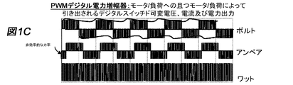
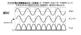
従来のデジタルパルス幅変調(PWM)と異なり、制御された共振インプリメンテーションは、最小負荷又はライン(ACグリッド)への逆のシステム電力反射を有する。図1Aは、PWM、及びこのタイプのデジタルスイッチングには一般的であり且つPWMインプリメンテーションの結果としてグリッドへ反射される信号歪みを示す。上記で言及したように、図1A〜Dには示されていないが、しかしモータ、電力コントローラ及び電源によって見られる他の多くの高速高電力スイッチング問題及び重大問題が存在する。恐らく、最も意味深いことには、acグリッドが、同様に損傷される可能性がある。今日のPWMベースのシステムの使用及び値を制限するのは、複数の高調波のこの連続電力反射、電気ノイズスパイク、及び更に悪いものである。対照的に、共振動作において、制御された共振によって電力を供給されるモータを用いれば、ACラインに対する電力需要は、典型的には、他のACラインにより接続された電気モータによって通常必要とされる時間の1/4よりはるかに少なく発生する。また、制御された共振を用いれば、たとえ負荷又はモータ電力が、図12C及び図13Cに示されているようにAC(双方向)であっても、誘導負荷(図11B、12B、13B)、及び最も重要なことにはACライン又はグリッド電力(図11A、12A、13A)への制御された共振コントローラ電力は、パルスAC又はDCである。図12及び図13に示されているように、DCパルシングは、正又は負の電圧共振で実行されても良い。また、図11〜15におけるこれらの電力プロットから分かるように、制御された共振の場合に、モータ転流を維持するための、最低量の時間通りの又は電力ラインの需要が存在する。制御された共振を用いたこの低減された電力時間需要は、ACライン利用及びモータ転流用の多くの新しい選択肢を可能にする。
制御された共振モータ共振転流が結合された場合に、共振クラスC増幅器動作に似ている非常に高い効率が生じる。優れた負荷整合を備えた状態において、クラスC動作効率をさえ超える最適なパルス駆動電圧、電流位相調整、及び時限駆動周波数モータ効率が生じ得る。通常の電気クラスC動作において、実際的な一次電気共振限界が存在する。何故なら、回路コンポーネントが、固定された静的な値のパラメータを有するからである。制御された共振によって電力を供給される回転誘導モータ配置において、負荷(モータ、装置又はシステム)は、静的な電気パラメータを有するだけでなく、それらはまた、電気−機械特性を有し、且つクラス「C」回路変数とは異なる。これらの電気−機械特性の幾つかは、固定されるか又は静的であるが、しかし他のものは、変化し動的である。モータは、DC抵抗、DCリアクタンス、回転子及び固定子サイズ等の幾つかの固定された属性を有するが、しかしそれはまた、フラックス、磁界及びより多くのものをもたらし変更する動的AC抵抗、動的ACリアクタンス、回転動作を有する。
通常のクラスC共振の例において、負荷は、典型的には同調タンク型電子回路である。我々は、固定された主要な発振モードを見つける。万一電子回路コンポーネントパラメータを変更した場合に、発振の減衰が発生し、恐らくシステム共振を終了させることになろう。制御された共振の場合に、我々は、有益な安定性の異常を観察した。帯域幅又は「Q」値は、かかる正確に同調された中心発振周波数を有しない。モータが、かなりの量の逆起電力(EMF)(フラックス、電流及び遠心力)を発生しているので、モータは、広く寛容である。比較して言えば、電気−機械特性は、共振動作帯域幅を拡張し増加させる。それがとても広く寛容であるので、図14C及び図15Bが示すように、単一の制御された共振ドライブから同時に2つ以上の独立誘導機械を駆動することが可能である。モータ速度が異なる場合にさえ、両方のモータは、図11〜15が示すように、各モータが、互いに且つ基本駆動周波数に対して或る割合で共振動作を有する限り、単一の制御された共振によって、共同して電力を供給され得る。これは、「2重共振」、即ち、そこから個別の誘導モータのそれぞれが、制御された共振を利用することによって「スマートグリッド」及びはるかに効率的なACグリッドに大きな後押しを提供する「2重共振」を達成するという考えであることに留意されたい。
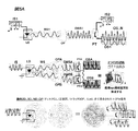
図6及び図7は、両方とも、制御された共振機器のブロック図、流れ図及び概略図を介して、実際のインプリメンテーションの例を示す。図7Aは、セクションfが、クラス「GP」動作用の共振駆動信号をイネーブルにできるサブ回路であるOP/GP設計コントローラの完全なシステム回路インプリメンテーションである。図7Bは、ブロック図である図6Aに伴う新しい回路サブセット又は「ドータ基板回路」であり、これは、誘導共振を達成する解決法に適用される、且つ解決法を提供するOP/GP技術を用いるための、以前に開示されたアプローチの異なる物理的な実施形態を与える。
パルスDC(直流)信号でAC(交流)非同期機を転流することは、交流モータが動作するために必要とするものに対して反直観的である。DCパルスは、通常、AC回転子に対して制動力を示し、且つロックされた回転子状態さえ引き起こすことができる。しかしながら、これは、転流パルス電圧信号が、それがモータ転流を引き起こし維持できるような方法で、計算され、時間を調整され、且つ十分に素早く実行される場合には、事実ではない。モータ内の誘導された崩壊磁界(磁束)と周期パルスを同期させることができるシステム及び方法は、モータ共振又は構成的な転流パターンを達成することができる。これらの同期周期パルスは、モータ巻線、コンデンサ及び回転子を介してルーティングすることができる。DC電圧で発生する制動効果ではなく、これらの内部電気−機械素子の適切な大きさ、同期及び使用は、内部の構成的なモータ発振が発生できるようにし、モータ発振が、今度は、同期されたモータ回転を巻線磁界発振及び継続される構成的な転流へと駆動し維持する。
下記は、限定するわけではないが、控え目なコンポーネントだけ(即ち、CMOS等ではない)を使用する周波数分割技術の実現を含むVHzサブ回路の可能な一実施形態の説明である。その目的は、光/電気コンポーネント及び支援回路の使用によって達成される。結果としての回路は、本来アナログであり、連続的に可変で瞬間的な演算である。図16に示されている回路は、2つの別個のサブ回路を含む。光学装置130の左側のコンポーネントは、周波数分割/乗算サブ回路を構成する。光学装置130の右側のコンポーネントは、実時間システムフィードバック、集積化及び光混合を実行する。
抵抗器108を通る電流はゼロになる。
PNPトランジスタ112は、導通ではなくなる。
トランジスタNPN114は、(電解キャップ117及び110における充電ゆえに)逆にバイアスをかけられる。
これは、トランジスタ112及び114が開になり、回路から切断されることに帰着する。
ポテンショメータ118、抵抗器119及びオプト電気装置142は、RCネットワークの「R」コンポーネントとして結局は働く別個の直列/並列ネットワーク配置を構成する。ポテンショメータの設定及び入力オプト制御装置142の値は、このRCネットワークに関連する「時定数」を制御する。このネットワークの根本的な特徴は、我々が、光学的にRC時定数回路を制御し、RC時定数回路が、結局は、電力電子回路の実際の周波数を制御することである。第2の電流ブリード経路は、ツェナーダイオード120を通過し、且つ抵抗器124にわたる電圧を発現する。抵抗器124にわたって発現された電圧は、電解コンデンサ117にわたる電圧−(マイナス)ツェナー120電圧と等しい。ツェナーダイオード120用の電圧値は、上記のRC回路の「R」コンポーネントがそれらの正常値にある場合に、抵抗器124にわたる電圧が負荷サイクルの50%にわたってゼロになるように、選択される。これは、中間設定であり、中間におけるポテンショメータ118及び/又はオプト140、226を促進し、且つ時定数周波数を容易に増加又は低減させる。抵抗器124にわたる電圧の「水平化」はまた、オプトカプラー126、127を正しく作動しない「トリクル電流」に対して保護する。
抵抗器124にわたって発現された電圧は、抵抗器121、122、123に結び付けられる。ポテンショメータ125のバランスを保つことは、コンポーネント許容誤差を調整するために、且つ3つの基本動作モードの1つを適応させるために利用される。
1. 標準、バランス、対称周波数分割及び乗算。
2. 非対称周波数分割及び乗算であり、それは、コンプレッサ、ポンプなどの非対称非線形負荷に有用になり得る。
3. 完全な非対称性を有する片面クラスGP動作−。
回路に示されている特定のオプト装置126及び127は、単に例示目的である。実際上、様々な装置が実現され得ることが分かった。例えば、装置の非限定的リストは、次のとおりである。
1. 標準BJT型の単一接合オプトカプラー。
2. ダーリントン型BJTオプトカプラー。
3. 硫化CADセル/LED組み合わせ装置。
4. 複数のCADセル、単一のLED。
5. 複数のLED、単一のCADセル。
1. ESDから装置を保護するために、
2. 逆電圧状態をブロックするために、
3. 回路安定性及び寿命を向上させるために、
必要とされる。
1. G=正弦トレースは、(2で割られた)ACライン入力電圧である。
2. R=(2で割られた)電力電子駆動回路のOP出力である。
3. B=電解コンデンサ117の「+」に存在する電圧である。
1. 入力電圧の基本周波数は、電解キャップ117上で2で明白に割られる。
2. RC時定数動作。
3. ライン周波数と電解部117の「+」において発現される制御電圧との間の位相遅延関係。
図23に示されているように、そこに示されている概略図は、図16から完全な概略図を取り出したものである。それは、回路の第2の光プロセッサセクションを示す。この回路の目的は、光信号が、以前に開示された第1のステージからの光学装置と混合されるか又はそれと共に「コプログラム」される、光学的に結合された閉回路フィードバックトポロジを提供することである。
OPサブ回路は、入力電圧を、光学的にプログラムされた対応する出力の抵抗に変換し、ここで、
V(t)=電力システムの出力であり、
VHz(t)=システム伝達関数であり、
R=対応する出力を光学的に計算された抵抗である。
Claims (23)
- 少なくとも1つの入力電気信号から出力制御信号を生成するためのプログラムド信号プロセッサであって、前記出力制御信号が、前記出力制御信号をアナログ電力信号として受信する目標電力装置及び前記目標電力装置上の負荷の共振特性を含む複数の共振制御パラメータを含むように、前記プログラムド信号プロセッサによって前記少なくとも1つの入力電気信号から生成されるプログラムド信号プロセッサを含んでおり、
前記プログラムド信号プロセッサが、前記目標電力装置用の前記複数の共振制御パラメータを含む前記出力制御信号を生成するために、複数の多次元パラメータプロファイル及び前記複数の多次元パラメータプロファイル内の少なくとも1つのグラフィックパルス共振機能を含むオプトプログラムを実行するオプトプロセッサであることを特徴とするアナログ電気制御システム。 - 請求項1に記載のアナログ電気制御システムにおいて、前記プログラムド信号プロセッサが、前記出力制御信号の共振及び前記目標電力装置の動作を達成し維持するために、前記複数の共振制御パラメータのそれぞれのために、前記目標電力装置において減衰磁界を誘導する周期電圧パルスを前記出力制御信号に注入することを特徴とするアナログ電気制御システム。
- 請求項1に記載のアナログ電気制御システムにおいて、前記複数の多次元パラメータプロファイルが、少なくとも3次元を含むことを特徴とするアナログ電気制御システム。
- 請求項1に記載のアナログ電気制御システムにおいて、前記複数の多次元パラメータプロファイルが、少なくとも1つの制御出力信号を定義する複数の同時入力を含むことを特徴とするアナログ電気制御システム。
- 請求項1に記載のアナログ電気制御システムにおいて、前記複数の多次元パラメータプロファイルが、多次元制御出力信号を定義する少なくとも1つの入力を含むことを特徴とするアナログ電気制御システム。
- 請求項1に記載のアナログ電気制御システムにおいて、前記プログラムド信号プロセッサが、前記出力制御信号が前記目標電力装置に電力を供給するオプトプログラムドコントローラであることを特徴とするアナログ電気制御システム。
- 請求項1に記載のアナログ電気制御システムにおいて、前記オプトプログラムが、次のもの、即ち、振幅、周波数、タイミング、位相、ベクトル、及び形状から選択される前記複数の多次元パラメータプロファイルの少なくとも1つの特性のグラフィカル制御を含むことを特徴とするアナログ電気制御システム。
- 請求項1に記載のアナログ電気制御システムにおいて、前記オプトプログラムの前記グラフィックパルス共振機能が、前記共振制御パラメータの少なくとも1つのための共振周波数及び振幅を用い、前記出力制御信号における周期電圧パルスを生成することを特徴とするアナログ電気制御システム。
- 請求項1に記載のアナログ電気制御システムにおいて、前記入力電気信号が、直流であり、前記オプトプログラムが、振幅及び周波数変調を用いて、前記入力電気信号に適用される可変で正及び負のパルスのグラフィカル制御を含むことを特徴とするアナログ電気制御システム。
- 請求項1に記載のアナログ電気制御システムにおいて、前記プログラムド信号プロセッサが、制御可能な装置状態を検知するためのセンサ信号入力であって、前記目標電力装置の閉ループ制御に前記信号入力を統合するためのセンサ信号入力をさらに含むことを特徴とするアナログ電気制御システム。
- 請求項10に記載のアナログ電気制御システムにおいて、前記制御可能な装置が、最小値及び最大値を備えた動作範囲を有し、前記プログラムド信号プロセッサが、前記目標電力装置用の少なくとも1つの共振制御パラメータを用いて共振を維持するために、前記センサ信号入力に基づいて前記出力制御信号を自動的に変更することを特徴とするアナログ電気制御システム。
- 請求項1に記載のアナログ電気制御システムにおいて、前記複数の共振制御パラメータが、前記目標電力装置及び前記目標電力装置上の負荷の共振特性を含むことを特徴とするアナログ電気制御システム。
- 請求項1に記載のアナログ電気制御システムにおいて、前記複数の共振制御パラメータが、共振を達成し維持するために要求される前記入力電気信号の特性を含むことを特徴とするアナログ電気制御システム。
- 請求項1に記載のアナログ電気制御システムにおいて、前記出力制御信号が、共通の入力電気信号を用いて共振を達成し維持するために、複数の目標電力装置を制御し、前記複数の目標電力装置のそれぞれが、異なる共振制御パラメータを有することを特徴とするアナログ電気制御システム。
- 請求項1に記載のアナログ電気制御システムにおいて、前記プログラムド信号プロセッサが、前記目標電力装置の50%を超える負荷サイクルを駆動する前記出力制御信号を生成するために、前記入力電気信号の50%未満の電力を用いる少なくとも1つのプログラム可能な負荷サイクル増幅機能を含むことを特徴とするアナログ電気制御システム。
- 請求項15に記載のアナログ電気制御システムにおいて、前記少なくとも1つのプログラム可能な負荷サイクル増幅機能が、前記入力電気信号の入力周波数の、整数、非整数、分数、部分的、及び入力周波数より大きい分割のための選択肢を含むことを特徴とするアナログ電気制御システム。
- 請求項1に記載のアナログ電気制御システムにおいて、前記目標電力装置が、次のもの、即ち、電気モータ、誘導ヒータ、抵抗ヒータ、光源、波発生器、磁界発生器、発電機、変圧器、誘導子、コンデンサ、又はエネルギ蓄積装置の少なくとも1つであることを特徴とするアナログ電気制御システム。
- 請求項17に記載のアナログ電気制御システムにおいて、前記目標電力装置が、電気モータであり、前記プログラムド信号プロセッサが、次の結果、即ち、トルク制御、速度制御、電力制御、エネルギ効率、及び負荷特性の少なくとも1つに対して前記電気モータを制御するために、前記複数の共振制御パラメータを用いることを特徴とするアナログ電気制御システム。
- 請求項18に記載のアナログ電気制御システムにおいて、前記プログラムド信号プロセッサが、定義された関係における次のパラメータ、即ち、極数、モータ入力信号、回転子滑り率、ピーク位相電圧、二乗平均平方根電圧、回転子抵抗、固定子抵抗、回転子リアクタンス、固定子リアクタンス、総抵抗、及び総リアクタンスを含む電気モータの数学モデルを用いてプログラムされることを特徴とするアナログ電気制御システム。
- 請求項18に記載のアナログ電気制御システムにおいて、前記プログラムド信号プロセッサが、ACモータモデリング用の次の式、
を用いる前記電気モータの数学モデルを用いてプログラムされることを特徴とするアナログ電気制御システム。 - 電気入力部と、
装置負荷と、
前記装置負荷を駆動する電力電気変換装置と、
前記電気入力部及び前記電力電気変換装置を用いて、前記装置負荷を制御するためのプログラムド信号プロセッサであって、前記電力電気変換装置の共振を達成し維持するように複数の共振制御パラメータのそれぞれに対して減衰磁界を誘導するために、周期電圧パルスを前記電力電気変換装置に注入するプログラムド信号プロセッサと、
を含んでおり、
前記プログラムド信号プロセッサが、前記複数の共振制御パラメータを生成するために、複数の多次元パラメータプロファイル及び前記複数の多次元パラメータプロファイル内の少なくとも1つのグラフィックパルス共振機能を含むオプトプログラムを実行するオプトプロセッサであることを特徴とする電気的に接続される電力装置。 - 電気信号入力部と、
制御信号出力部と、
オプトプロセッサと、
少なくとも1つの入力電気信号から出力制御信号を生成するためのオプトプログラムであって、複数の多次元パラメータプロファイル及び前記複数の多次元パラメータプロファイル内の少なくとも1つのグラフィックパルス共振機能が、前記出力制御信号を受信する目標電力装置用に複数の共振制御パラメータを生成するオプトプログラムと、
を含むことを特徴とするオプトプログラムドコントローラ。 - 請求項22に記載のオプトプログラムドコントローラにおいて、前記オプトプロセッサが、前記目標電力装置の前記出力制御信号及び動作の共振を達成し維持するように、前記複数の共振制御パラメータのそれぞれに対して、前記目標電力装置における減衰磁界を誘導する周期電圧パルスを前記出力制御信号に注入することを特徴とするオプトプログラムドコントローラ。
Applications Claiming Priority (3)
| Application Number | Priority Date | Filing Date | Title |
|---|---|---|---|
| US201261583337P | 2012-01-05 | 2012-01-05 | |
| US61/583,337 | 2012-01-05 | ||
| PCT/US2013/020344 WO2013103865A1 (en) | 2012-01-05 | 2013-01-04 | Controlled resonance in electrical power devices |
Publications (2)
| Publication Number | Publication Date |
|---|---|
| JP2015508635A JP2015508635A (ja) | 2015-03-19 |
| JP6189862B2 true JP6189862B2 (ja) | 2017-08-30 |
Family
ID=48745444
Family Applications (1)
| Application Number | Title | Priority Date | Filing Date |
|---|---|---|---|
| JP2014551366A Active JP6189862B2 (ja) | 2012-01-05 | 2013-01-04 | 電力装置における制御された共振 |
Country Status (4)
| Country | Link |
|---|---|
| US (2) | US9419543B2 (ja) |
| JP (1) | JP6189862B2 (ja) |
| BR (1) | BR112014016498A8 (ja) |
| WO (1) | WO2013103865A1 (ja) |
Families Citing this family (7)
| Publication number | Priority date | Publication date | Assignee | Title |
|---|---|---|---|---|
| WO2013098647A2 (en) * | 2011-12-28 | 2013-07-04 | Delta Electronic (Thailand) Public Company Limited | Resonant bi-directional dc-ac converter |
| US9231750B2 (en) * | 2013-03-13 | 2016-01-05 | Semtech Corporation | Low-power, low-latency architecture for telecom and datacom multiplexers and demultiplexers |
| US10042375B2 (en) * | 2014-09-30 | 2018-08-07 | Honeywell International Inc. | Universal opto-coupled voltage system |
| US10396694B2 (en) * | 2016-03-17 | 2019-08-27 | General Electric Company | System and method for minimizing reactive current to limit rotor modulation index on a power converter |
| US10114981B2 (en) * | 2016-12-31 | 2018-10-30 | Intel Corporation | Architecture for telemetry and adaptive lifetime control of integrated circuits |
| US10541635B2 (en) | 2017-08-30 | 2020-01-21 | Quanten Technologies, Inc. | Motor system and control method |
| EP4068137B1 (en) * | 2020-05-29 | 2024-01-10 | Koh Young Technology Inc. | Apparatus and method for optimizing control parameter of solder printing apparatus |
Family Cites Families (19)
| Publication number | Priority date | Publication date | Assignee | Title |
|---|---|---|---|---|
| GB1492782A (en) | 1974-02-01 | 1977-11-23 | Nat Res Dev | Methods and apparatus for speed-control of induction motors |
| US4414535A (en) * | 1978-08-07 | 1983-11-08 | The Singer Company | Magnetic resonance gyro signal processor |
| US4629886A (en) * | 1983-03-23 | 1986-12-16 | Yokogawa Hokushin Electric Corporation | High resolution digital diffraction grating scale encoder |
| US4575179A (en) * | 1983-10-28 | 1986-03-11 | The United States Of America As Represented By The Secretary Of The Navy | Integrated optical signal processor using diffraction of light by magnetostatic waves |
| US5196775A (en) | 1991-02-20 | 1993-03-23 | Honeywell Inc. | Switched reluctance motor position by resonant signal injection |
| JPH0715983A (ja) * | 1993-06-24 | 1995-01-17 | Canon Inc | 振動波モータ駆動回路 |
| JPH0751983A (ja) | 1993-08-19 | 1995-02-28 | Star Micronics Co Ltd | 切削油の供給装置 |
| US6087654A (en) | 1995-02-27 | 2000-07-11 | Opto Generic Devices, Inc. | Encoder apparatus and methods |
| CN1256571C (zh) | 1995-02-27 | 2006-05-17 | 奥普托普通装置有限公司 | 编码器装置和方法 |
| JP3759571B2 (ja) * | 2000-03-01 | 2006-03-29 | 三洋電機株式会社 | リニアモータ駆動往復機構の制御装置 |
| JP3824919B2 (ja) * | 2001-12-06 | 2006-09-20 | アスモ株式会社 | 超音波モータの制御装置、及び超音波モータの制御方法 |
| US7204429B2 (en) | 2004-04-28 | 2007-04-17 | Intelligent Power Management, Inc | Controller for forced-air HVAC system |
| US7797080B2 (en) | 2004-06-14 | 2010-09-14 | Ogd V-Hvac Inc. | Opto-programmed HVAC controller |
| JP5391579B2 (ja) * | 2008-05-15 | 2014-01-15 | 船井電機株式会社 | 振動素子 |
| JP5003589B2 (ja) | 2008-05-15 | 2012-08-15 | トヨタ自動車株式会社 | 短絡相特定方法 |
| JP5261794B2 (ja) * | 2008-09-03 | 2013-08-14 | 東芝ライテック株式会社 | 照明器具 |
| US8144438B2 (en) | 2008-10-03 | 2012-03-27 | General Electric Company | Motor control center communication system |
| WO2011020058A1 (en) | 2009-08-14 | 2011-02-17 | Opto Generic Devices, Inc. | Intelligent total air climate & cleaning conditioner |
| GB201006394D0 (en) * | 2010-04-16 | 2010-06-02 | Dyson Technology Ltd | Controller for a brushless motor |
-
2013
- 2013-01-04 WO PCT/US2013/020344 patent/WO2013103865A1/en active Application Filing
- 2013-01-04 BR BR112014016498A patent/BR112014016498A8/pt not_active Application Discontinuation
- 2013-01-04 US US14/370,576 patent/US9419543B2/en not_active Expired - Fee Related
- 2013-01-04 JP JP2014551366A patent/JP6189862B2/ja active Active
-
2016
- 2016-07-13 US US15/209,203 patent/US9859830B2/en not_active Expired - Fee Related
Also Published As
| Publication number | Publication date |
|---|---|
| US20150002068A1 (en) | 2015-01-01 |
| BR112014016498A8 (pt) | 2023-03-14 |
| BR112014016498A2 (pt) | 2017-06-13 |
| JP2015508635A (ja) | 2015-03-19 |
| US20170012562A1 (en) | 2017-01-12 |
| US9859830B2 (en) | 2018-01-02 |
| WO2013103865A1 (en) | 2013-07-11 |
| US9419543B2 (en) | 2016-08-16 |
Similar Documents
| Publication | Publication Date | Title |
|---|---|---|
| JP6189862B2 (ja) | 電力装置における制御された共振 | |
| Singh et al. | Power factor correction in bridgeless-Luo converter-fed BLDC motor drive | |
| Shao et al. | Low-cost variable speed drive based on a brushless doubly-fed motor and a fractional unidirectional converter | |
| Singh et al. | Power quality improvements in a zeta converter for brushless DC motor drives | |
| Barati et al. | Generalized vector control for brushless doubly fed machines with nested-loop rotor | |
| Anand et al. | Modified dual output cuk converter-fed switched reluctance motor drive with power factor correction | |
| Salah et al. | Implementation of PWM control strategy for torque ripples reduction in brushless DC motors | |
| Kumaresan et al. | Design and control of shunt active power filter for power quality improvement of utility powered brushless DC motor drives | |
| Zhou et al. | Laboratory control implementations for doubly-fed machines | |
| Kommula et al. | PFC based SEPIC converter fed BLDC motor with torque ripple minimization approach | |
| Kale et al. | Analysis of torque and flux ripple factor for DTC and SVM-DTC of induction motor drive | |
| Karthikeyan et al. | DC-DC converter CSI fed BLDC motor for defence applications | |
| Zhong | AC Ward Leonard drive systems: Revisiting the four-quadrant operation of AC machines | |
| Kaliappan et al. | Design and Implementation of PFC CUK Converter-Based PMBLDCM Drive | |
| Babu et al. | FPGA based implementation of brushless DC motor drive using single current sensor and comparison with conventional method | |
| Sri et al. | A Comparative Analysis of Zeta and Bridgeless LUO PFC Converters Fedbldc Motors with PI-Controller | |
| Dolly et al. | Enhancement of PFC and torque ripple reduction using bl buck-boost converter fed hcc bldc drive | |
| Kudukkengal et al. | Vector control of VSI fed 3-phase SCIM with high voltage gain and two input boost stage DC-DC converter | |
| Umayal et al. | Modeling and simulation of pfc sepic converter fed pmbldc drive for mining application | |
| Hegde et al. | Improvement of Power Quality and Speed Regulation of A BLDC Motor Drive Using an Interleaved Converter | |
| Usman et al. | Z-Source Inverter based Indirect Field Oriented Control with Synchronous Current Injection and feed-forward CEMF compensation for an induction motor drive | |
| Doss et al. | A cost effective speed control method for bldc motor drive | |
| Maharajan et al. | Analysis of low harmonics and high efficient BLDC motor drive system for automotive application | |
| RAMYA et al. | Enhancement of Power Factor with Fuzzy Controlled Bridgeless Buck-Boost Converter-Fed BLDCM Drive | |
| Saravanan et al. | Simulation and Experimental Validation of PFC Zeta Converter Fed PMSM Drive for Variable Speed Applications |
Legal Events
| Date | Code | Title | Description |
|---|---|---|---|
| A621 | Written request for application examination |
Free format text: JAPANESE INTERMEDIATE CODE: A621 Effective date: 20151225 |
|
| A521 | Request for written amendment filed |
Free format text: JAPANESE INTERMEDIATE CODE: A523 Effective date: 20160205 |
|
| A977 | Report on retrieval |
Free format text: JAPANESE INTERMEDIATE CODE: A971007 Effective date: 20161109 |
|
| A131 | Notification of reasons for refusal |
Free format text: JAPANESE INTERMEDIATE CODE: A131 Effective date: 20161220 |
|
| A601 | Written request for extension of time |
Free format text: JAPANESE INTERMEDIATE CODE: A601 Effective date: 20170321 |
|
| A521 | Request for written amendment filed |
Free format text: JAPANESE INTERMEDIATE CODE: A523 Effective date: 20170518 |
|
| TRDD | Decision of grant or rejection written | ||
| A01 | Written decision to grant a patent or to grant a registration (utility model) |
Free format text: JAPANESE INTERMEDIATE CODE: A01 Effective date: 20170704 |
|
| A61 | First payment of annual fees (during grant procedure) |
Free format text: JAPANESE INTERMEDIATE CODE: A61 Effective date: 20170803 |
|
| R150 | Certificate of patent or registration of utility model |
Ref document number: 6189862 Country of ref document: JP Free format text: JAPANESE INTERMEDIATE CODE: R150 |
|
| R250 | Receipt of annual fees |
Free format text: JAPANESE INTERMEDIATE CODE: R250 |
|
| R250 | Receipt of annual fees |
Free format text: JAPANESE INTERMEDIATE CODE: R250 |
|
| R250 | Receipt of annual fees |
Free format text: JAPANESE INTERMEDIATE CODE: R250 |
|
| R250 | Receipt of annual fees |
Free format text: JAPANESE INTERMEDIATE CODE: R250 |