JP6185964B2 - Cartridge type cosmetic container - Google Patents

Cartridge type cosmetic container Download PDF

Info

Publication number
JP6185964B2
JP6185964B2 JP2015157546A JP2015157546A JP6185964B2 JP 6185964 B2 JP6185964 B2 JP 6185964B2 JP 2015157546 A JP2015157546 A JP 2015157546A JP 2015157546 A JP2015157546 A JP 2015157546A JP 6185964 B2 JP6185964 B2 JP 6185964B2
Authority
JP
Japan
Prior art keywords
cartridge
main body
female screw
cylinder
outer cylinder
Prior art date
Legal status (The legal status is an assumption and is not a legal conclusion. Google has not performed a legal analysis and makes no representation as to the accuracy of the status listed.)
Active
Application number
JP2015157546A
Other languages
Japanese (ja)
Other versions
JP2017035235A5 (en
JP2017035235A (en
Inventor
大庭 淳
淳 大庭
Current Assignee (The listed assignees may be inaccurate. Google has not performed a legal analysis and makes no representation or warranty as to the accuracy of the list.)
Suzuno Kasei Co Ltd
Original Assignee
Suzuno Kasei Co Ltd
Priority date (The priority date is an assumption and is not a legal conclusion. Google has not performed a legal analysis and makes no representation as to the accuracy of the date listed.)
Filing date
Publication date
Application filed by Suzuno Kasei Co Ltd filed Critical Suzuno Kasei Co Ltd
Priority to JP2015157546A priority Critical patent/JP6185964B2/en
Priority to US15/748,703 priority patent/US10542813B2/en
Priority to PCT/JP2016/072399 priority patent/WO2017026305A1/en
Priority to EP16835002.3A priority patent/EP3332667B1/en
Publication of JP2017035235A publication Critical patent/JP2017035235A/en
Publication of JP2017035235A5 publication Critical patent/JP2017035235A5/ja
Application granted granted Critical
Publication of JP6185964B2 publication Critical patent/JP6185964B2/en
Active legal-status Critical Current
Anticipated expiration legal-status Critical

Links

Images

Classifications

    • AHUMAN NECESSITIES
    • A45HAND OR TRAVELLING ARTICLES
    • A45DHAIRDRESSING OR SHAVING EQUIPMENT; EQUIPMENT FOR COSMETICS OR COSMETIC TREATMENTS, e.g. FOR MANICURING OR PEDICURING
    • A45D40/00Casings or accessories specially adapted for storing or handling solid or pasty toiletry or cosmetic substances, e.g. shaving soaps or lipsticks
    • A45D40/10Casings wherein a spring presses the lipstick or like solid into the position for use or into the retracted position
    • AHUMAN NECESSITIES
    • A45HAND OR TRAVELLING ARTICLES
    • A45DHAIRDRESSING OR SHAVING EQUIPMENT; EQUIPMENT FOR COSMETICS OR COSMETIC TREATMENTS, e.g. FOR MANICURING OR PEDICURING
    • A45D40/00Casings or accessories specially adapted for storing or handling solid or pasty toiletry or cosmetic substances, e.g. shaving soaps or lipsticks
    • A45D40/02Casings wherein movement of the lipstick or like solid is a sliding movement
    • A45D40/04Casings wherein movement of the lipstick or like solid is a sliding movement effected by a screw
    • AHUMAN NECESSITIES
    • A45HAND OR TRAVELLING ARTICLES
    • A45DHAIRDRESSING OR SHAVING EQUIPMENT; EQUIPMENT FOR COSMETICS OR COSMETIC TREATMENTS, e.g. FOR MANICURING OR PEDICURING
    • A45D40/00Casings or accessories specially adapted for storing or handling solid or pasty toiletry or cosmetic substances, e.g. shaving soaps or lipsticks
    • A45D40/20Pencil-like cosmetics; Simple holders for handling stick-shaped cosmetics or shaving soap while in use
    • A45D40/205Holders for stick-shaped cosmetics whereby the stick can move axially relative to the holder
    • AHUMAN NECESSITIES
    • A45HAND OR TRAVELLING ARTICLES
    • A45DHAIRDRESSING OR SHAVING EQUIPMENT; EQUIPMENT FOR COSMETICS OR COSMETIC TREATMENTS, e.g. FOR MANICURING OR PEDICURING
    • A45D40/00Casings or accessories specially adapted for storing or handling solid or pasty toiletry or cosmetic substances, e.g. shaving soaps or lipsticks
    • A45D2040/0025Details of lipstick or like casings
    • AHUMAN NECESSITIES
    • A45HAND OR TRAVELLING ARTICLES
    • A45DHAIRDRESSING OR SHAVING EQUIPMENT; EQUIPMENT FOR COSMETICS OR COSMETIC TREATMENTS, e.g. FOR MANICURING OR PEDICURING
    • A45D40/00Casings or accessories specially adapted for storing or handling solid or pasty toiletry or cosmetic substances, e.g. shaving soaps or lipsticks
    • A45D40/20Pencil-like cosmetics; Simple holders for handling stick-shaped cosmetics or shaving soap while in use
    • A45D2040/204Pencil-like cosmetics; Simple holders for handling stick-shaped cosmetics or shaving soap while in use the cosmetic being in a cartridge
    • AHUMAN NECESSITIES
    • A45HAND OR TRAVELLING ARTICLES
    • A45DHAIRDRESSING OR SHAVING EQUIPMENT; EQUIPMENT FOR COSMETICS OR COSMETIC TREATMENTS, e.g. FOR MANICURING OR PEDICURING
    • A45D40/00Casings or accessories specially adapted for storing or handling solid or pasty toiletry or cosmetic substances, e.g. shaving soaps or lipsticks
    • A45D40/20Pencil-like cosmetics; Simple holders for handling stick-shaped cosmetics or shaving soap while in use
    • A45D40/205Holders for stick-shaped cosmetics whereby the stick can move axially relative to the holder
    • A45D2040/208Holders for stick-shaped cosmetics whereby the stick can move axially relative to the holder the relative movement being made by a rotating action, e.g. effected by a screw
    • BPERFORMING OPERATIONS; TRANSPORTING
    • B43WRITING OR DRAWING IMPLEMENTS; BUREAU ACCESSORIES
    • B43KIMPLEMENTS FOR WRITING OR DRAWING
    • B43K21/00Propelling pencils
    • B43K21/02Writing-core feeding mechanisms
    • B43K21/08Writing-core feeding mechanisms with the writing-cores fed by screws

Description

本発明は、化粧料が収容されたカートリッジ体が着脱自在に装着されるカートリッジ式化粧料容器に関する。   The present invention relates to a cartridge-type cosmetic container in which a cartridge body containing cosmetics is detachably mounted.

従来から、カートリッジ体内の化粧料を、カートリッジ体の前端開口孔より微動に進出させるカートリッジ式化粧料容器が用いられている。カートリッジ式化粧料容器には、カートリッジ体に繰出機構が設けられず、カートリッジ体とは完全に分離独立して繰出機構が設けられるものがある。   2. Description of the Related Art Conventionally, a cartridge-type cosmetic container that allows a cosmetic in a cartridge body to advance finely through a front end opening hole of the cartridge body has been used. Some cartridge-type cosmetic containers are not provided with a feeding mechanism in the cartridge body and are provided with a feeding mechanism completely separated and independent from the cartridge body.

特許文献1には、外周に雄ねじが形成される押棒と、カートリッジ体が本体筒に取り付けられた状態で雄ねじと螺合する雌ねじが内周に形成される一対の駒体と、一対の駒体に当接するコイルばねと、を備えるカートリッジ式化粧料容器が開示される。カートリッジ体が本体筒から取り外されると、一対の駒体はコイルばねの付勢力により軸方向に移動する。このとき、一対の駒体は、本体筒の内周に設けられた離間ガイド部により、押棒から離間する方向に案内される。その結果、駒体の雌ねじと押棒の雄ねじとの螺合が解除され、押棒が繰出後退限まで移動する。   In Patent Document 1, a push rod having a male screw formed on the outer periphery, a pair of frame members formed on the inner periphery with a female screw screwed to the male screw in a state where the cartridge body is attached to the main body cylinder, and a pair of frame members A cartridge-type cosmetic container comprising a coil spring abutting on the cartridge is disclosed. When the cartridge body is removed from the main body cylinder, the pair of pieces move in the axial direction by the biasing force of the coil spring. At this time, the pair of pieces are guided in a direction away from the push rod by a separation guide portion provided on the inner periphery of the main body cylinder. As a result, the screw engagement between the female screw of the frame body and the male screw of the push rod is released, and the push rod moves to the extended retreat limit.

また、特許文献1に開示されるカートリッジ式化粧料容器は、カートリッジ体が本体筒に取り付けられるときに、押棒に近接する方向に一対の駒体を案内する近接ガイド部を備える。一対の駒体が押棒を挟むように押棒に近接するので、一対の駒体の雌ねじと押棒の雄ねじとの螺合が解除される方向への押棒の移動が一対の駒体により制限される。   In addition, the cartridge-type cosmetic container disclosed in Patent Document 1 includes a proximity guide portion that guides a pair of pieces in a direction close to the push rod when the cartridge body is attached to the main body cylinder. Since the pair of pieces close to the push rod so as to sandwich the push rod, the movement of the push rod in a direction in which the screwing of the female screw of the pair of pieces and the male screw of the push rod is released is restricted by the pair of pieces.

特開2014−161637号公報JP 2014-161637 A

しかしながら、特許文献1に開示されるカートリッジ式化粧料容器では、カートリッジ体を本体筒に取り付ける際に、一方の駒体が他方に対して本体筒内でずれて移動する場合がある。この場合、一方の駒体がカートリッジ式化粧料容器の軸方向に対して傾き、コイルばねが当接する駒体の当接面が軸方向に対して傾くことがある。当接面が傾くことにより、コイルばねの付勢力が一方の駒体に偏って付与され、一方の駒体に通常よりも大きい付勢力が作用するおそれがある。   However, in the cartridge-type cosmetic container disclosed in Patent Document 1, when the cartridge body is attached to the main body cylinder, one piece body may be displaced in the main body cylinder relative to the other. In this case, one piece may be inclined with respect to the axial direction of the cartridge-type cosmetic container, and the contact surface of the piece with which the coil spring contacts may be inclined with respect to the axial direction. When the abutting surface is inclined, the biasing force of the coil spring is applied to one of the pieces in a biased manner, and a biasing force larger than usual may be applied to the one piece.

また、一方の駒体が他方に対して本体筒内でずれて移動すると、一対の駒体は、押棒の雄ねじに雌ねじが螺合せずに雌ねじのねじ山の頂部が雄ねじのねじ山の頂部に当接した状態で保持されるおそれがある。この状態の駒体に通常よりも大きい付勢力が作用すると、本体筒へのカートリッジ体の挿入が困難になり、カートリッジ体を本体筒の所定の位置まで挿入できなくなるおそれがある。その結果、一対の駒体の雌ねじと押棒の雄ねじとの螺合が解除される方向への押棒の移動が一対の駒体により制限されず、雌ねじと雄ねじとの螺合が弱くなるおそれがある。   In addition, when one piece moves out of the body cylinder with respect to the other, the pair of pieces do not engage with the male thread of the push rod, and the top of the female thread is at the top of the male thread. There is a risk of being held in contact. If an urging force larger than usual is applied to the piece body in this state, it becomes difficult to insert the cartridge body into the main body cylinder, and the cartridge body may not be inserted to a predetermined position of the main body cylinder. As a result, the movement of the push rod in the direction in which the screw engagement between the female screw of the pair of pieces and the male screw of the push rod is released is not limited by the pair of pieces, and the screw engagement between the female screw and the male screw may be weakened. .

本発明は、化粧料を確実に繰り出すことができるカートリッジ式化粧料容器を提供することを目的とする。   An object of this invention is to provide the cartridge type cosmetics container which can pay out cosmetics reliably.

本発明は、化粧料が収容されたカートリッジ体が取り付けられて用いられるカートリッジ式化粧料容器であって、前記カートリッジ体が着脱自在に取り付けられる本体筒と、前記本体筒に相対回転可能に設けられる駆動体と、外周に雄ねじが形成され、前記本体筒と前記駆動体との相対回転によって繰り出されて前記カートリッジ体内の化粧料を押し出す押棒と、前記押棒の外周に設けられる雌ねじ部材と、前記雌ねじ部材に形成され、前記カートリッジ体が前記本体筒に取り付けられる際に前記雌ねじ部材が前記カートリッジ体によって押圧されることにより、前記雄ねじと螺合する雌ねじ部と、前記雌ねじ部材を、前記本体筒の前端開口方向に付勢する付勢部材と、を備え、前記本体筒は、前記雌ねじ部と前記雄ねじとの螺合が解除される方向への前記押棒の移動を制限する制限部を有することを特徴とする。 The present invention is a cartridge-type cosmetic container that is used with a cartridge body containing cosmetics attached thereto, and is provided with a main body cylinder to which the cartridge body is detachably attached, and a relative rotation to the main body cylinder. A driving body, a male screw formed on the outer periphery, a push bar that is fed out by relative rotation between the main body cylinder and the driving body to push out cosmetics in the cartridge body, a female screw member provided on the outer periphery of the push bar, and the female screw When the cartridge body is attached to the main body cylinder when the cartridge body is attached to the main body cylinder, the internal thread member is pressed by the cartridge body, so that the internal thread portion and the internal thread member are connected to the main body cylinder. includes a biasing member for biasing the front end opening direction, wherein the main body tube is screwed with the male thread and the female screw portion is released Characterized in that it has a restriction that limits the movement of the push rod in the direction.

本発明では、本体筒が螺合解除方向への押棒の移動を制限する制限部を有するので、雌ねじ部材の雌ねじ部と押棒の雄ねじとを螺合させる際に複数の雌ねじ部材が必要とされない。付勢部材は1つの雌ねじ部材を付勢するので、複数の雌ねじ部材を用いる場合のように雌ねじ部材に通常よりも大きい付勢力が作用することはない。そのため、雌ねじ部材の雌ねじ部のねじ山の頂部が押棒の雄ねじのねじ山の頂部に当接しても、本体筒へのカートリッジ体の挿入が困難になることはない。したがって、カートリッジ体を本体筒の所望の位置まで挿入することができ、螺合解除方向への押棒の移動を本体筒の制限部により制限することができる。その結果、押棒は、本体筒と駆動体との相対回転に伴ってより確実に進退し、化粧料をカートリッジ体からより確実に繰り出すことができる。また、雌ねじ部材を1つにすることで、複数の雌ねじ部材を本体筒へ挿入する場合と比較して、カートリッジ式化粧料容器を細径化することができる。   In the present invention, since the main body cylinder has the limiting portion that restricts the movement of the push rod in the screw release direction, a plurality of female screw members are not required when the female screw portion of the female screw member and the male screw of the push rod are screwed together. Since the biasing member biases one female screw member, a larger biasing force than usual does not act on the female screw member as in the case of using a plurality of female screw members. Therefore, even if the top of the thread of the female thread portion of the female thread member abuts on the top of the thread of the male thread of the push rod, it is not difficult to insert the cartridge body into the main body cylinder. Therefore, the cartridge body can be inserted to a desired position of the main body cylinder, and the movement of the push rod in the screwing release direction can be restricted by the restriction portion of the main body cylinder. As a result, the push rod advances and retracts more reliably with the relative rotation of the main body cylinder and the driving body, and the cosmetic can be more reliably delivered from the cartridge body. Moreover, by using one female screw member, the cartridge-type cosmetic container can be made thinner compared to the case where a plurality of female screw members are inserted into the main body cylinder.

(a)は、本発明の第1の実施形態に係るカートリッジ式化粧料容器の正面の断面図であり、(b)は、図1(a)におけるA−A断面図であり、(c)は、図1(a)におけるB−B断面図である。(A) is sectional drawing of the front of the cartridge type cosmetics container which concerns on the 1st Embodiment of this invention, (b) is AA sectional drawing in Fig.1 (a), (c) These are BB sectional drawings in Drawing 1 (a). 本発明の第1の実施形態に係るカートリッジ式化粧料容器の繰出上昇限を示す正面の断面図である。It is sectional drawing of the front which shows the pay-out raise limit of the cartridge type cosmetic container which concerns on the 1st Embodiment of this invention. (a)は、カートリッジ体の正面の断面図であり、(b)は、キャップの正面の断面図であり、(c)は、カートリッジ外筒の正面図であり、(d)は、保持部材の正面図である。(A) is a front sectional view of the cartridge body, (b) is a front sectional view of the cap, (c) is a front view of the cartridge outer cylinder, and (d) is a holding member. FIG. (a)は、カートリッジ外筒の正面図であり、(b)は、カートリッジ外筒の側面図であり、(c)は、カートリッジ外筒の正面の断面図である。(A) is a front view of the cartridge outer cylinder, (b) is a side view of the cartridge outer cylinder, and (c) is a sectional view of the front surface of the cartridge outer cylinder. (a)は、カートリッジ式化粧料容器の正面の断面図であり、(b)は、図5(a)におけるC−C断面図であり、(c)は、図5(a)におけるD−D断面図である。(A) is sectional drawing of the front of a cartridge type cosmetic container, (b) is CC sectional drawing in Fig.5 (a), (c) is DD in FIG.5 (a). It is D sectional drawing. (a)は、本体外筒の正面の断面図であり、(b)は、図6(a)におけるE−E断面図である。(A) is sectional drawing of the front of a main body outer cylinder, (b) is EE sectional drawing in Fig.6 (a). (a)は、駆動体の正面図であり、(b)は、駆動体の平面図であり、(c)は、駆動体の正面の断面図である。(A) is a front view of a drive body, (b) is a top view of a drive body, (c) is sectional drawing of the front of a drive body. (a)は、押棒の正面図であり、(b)は、押棒の底面図であり、(c)は、押棒の正面の断面図である。(A) is a front view of a push rod, (b) is a bottom view of a push rod, (c) is sectional drawing of the front of a push rod. コイルばねの正面図である。It is a front view of a coil spring. (a)は、本体内筒の正面図であり、(b)は、本体内筒の平面図であり、(c)は、本体内筒の底面図であり、(d)は、本体内筒の正面の断面図である。(A) is a front view of an inner cylinder, (b) is a plan view of the inner cylinder, (c) is a bottom view of the inner cylinder, and (d) is an inner cylinder. FIG. (a)は、雌ねじ部材の正面図であり、(b)は、雌ねじ部材の平面図であり、(c)は、雌ねじ部材の底面図であり、(d)は、雌ねじ部材の側面図であり、(e)は、雌ねじ部材の正面の断面図である。(A) is a front view of the female screw member, (b) is a plan view of the female screw member, (c) is a bottom view of the female screw member, and (d) is a side view of the female screw member. And (e) is a front sectional view of the female screw member. (a)は、本発明の第2の実施形態に係るカートリッジ式化粧料容器の正面の断面図であり、(b)は、図12(a)におけるF−F断面図であり、(c)は、図12(a)におけるG−G断面図である。(A) is sectional drawing of the front of the cartridge type cosmetics container which concerns on the 2nd Embodiment of this invention, (b) is FF sectional drawing in Fig.12 (a), (c) These are GG sectional drawings in Drawing 12 (a). 本発明の第2の実施形態に係るカートリッジ式化粧料容器の繰出上昇限を示す正面の断面図である。It is front sectional drawing which shows the pay-out raise limit of the cartridge type cosmetics container which concerns on the 2nd Embodiment of this invention. (a)は、カートリッジ式化粧料容器の正面の断面図であり、(b)は、図14(a)におけるH−H断面図であり、(c)は、図14(a)におけるI−I断面図であり、(d)は、図14(a)におけるJ−J断面図であり、(e)は、図14(a)におけるK−K断面図である。(A) is sectional drawing of the front of a cartridge-type cosmetics container, (b) is HH sectional drawing in Fig.14 (a), (c) is I- in Fig.14 (a). It is I sectional drawing, (d) is JJ sectional drawing in Fig.14 (a), (e) is KK sectional drawing in Fig.14 (a). (a)は、本体外筒の正面の断面図であり、(b)は、図15(a)におけるL−L断面図であり、(c)は、図15(a)におけるM−M断面図である。(A) is sectional drawing of the front of a main body outer cylinder, (b) is LL sectional drawing in Fig.15 (a), (c) is MM sectional drawing in Fig.15 (a). FIG. (a)は、駆動体の正面図であり、(b)は、駆動体の平面図であり、(c)は、駆動体の正面の断面図である。(A) is a front view of a drive body, (b) is a top view of a drive body, (c) is sectional drawing of the front of a drive body. コイルばねの正面図である。It is a front view of a coil spring. (a)は、雌ねじ部材の正面図であり、(b)は、雌ねじ部材の平面図であり、(c)は、雌ねじ部材の底面図であり、(d)は、雌ねじ部材の側面図であり、(e)は、雌ねじ部材の正面の断面図である。(A) is a front view of the female screw member, (b) is a plan view of the female screw member, (c) is a bottom view of the female screw member, and (d) is a side view of the female screw member. And (e) is a front sectional view of the female screw member. (a)は、ラチェット部材の正面図であり、(b)は、ラチェット部材の平面図であり、(c)は、ラチェット部材の底面図であり、(d)は、図19(a)におけるN−N断面図であり、(e)は、ラチェット部材の側面図であり、(f)は、ラチェット部材の正面の断面図である。(A) is a front view of the ratchet member, (b) is a plan view of the ratchet member, (c) is a bottom view of the ratchet member, and (d) is a view in FIG. It is NN sectional drawing, (e) is a side view of a ratchet member, (f) is sectional drawing of the front of a ratchet member. (a)は、本発明の第3の実施形態に係るカートリッジ体の変形例の正面図であり、(b)は、カートリッジ外筒の正面の断面図であり、(c)は、図20(b)におけるO−O断面図であり、(d)は、保持部材の正面図であり、(e)は、図20(d)におけるP−P断面図である。(A) is a front view of the modification of the cartridge body which concerns on the 3rd Embodiment of this invention, (b) is sectional drawing of the front of a cartridge outer cylinder, (c) is FIG. It is OO sectional drawing in b), (d) is a front view of a holding member, (e) is PP sectional drawing in FIG.20 (d). (a)は、カートリッジ体の変形例の正面図であり、(b)は、カートリッジ体の変形例の正面の断面図である。(A) is a front view of the modification of a cartridge body, (b) is sectional drawing of the front of the modification of a cartridge body. (a)は、カートリッジ体の別の変形例の正面図であり、(b)は、カートリッジ外筒の変形例の正面の断面図であり、(c)は、カートリッジ体の変形例の正面の断面図である。(A) is a front view of another modified example of the cartridge body, (b) is a front sectional view of the modified example of the cartridge outer cylinder, and (c) is a front view of the modified example of the cartridge body. It is sectional drawing.

以下、図面を参照して、本発明の実施形態について説明する。   Embodiments of the present invention will be described below with reference to the drawings.

(第1の実施形態)
図1から図11を参照して、本発明の第1の実施形態に係るカートリッジ式化粧料容器1について説明する。
(First embodiment)
A cartridge type cosmetic container 1 according to a first embodiment of the present invention will be described with reference to FIGS.

まず、図1及び図2を参照して、カートリッジ式化粧料容器1の全体構成について説明する。   First, with reference to FIG.1 and FIG.2, the whole structure of the cartridge type cosmetic container 1 is demonstrated.

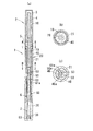
カートリッジ式化粧料容器1は、化粧料4が収容されたカートリッジ体2が取り付けられて用いられるものである。カートリッジ式化粧料容器1は、図1に示すように、カートリッジ体2が着脱自在に取り付けられる本体筒20と、本体筒20に対して同軸に、かつ相対回転可能に取り付けられる駆動体30と、外周に雄ねじ61aが形成され、本体筒20と駆動体30との相対回転によって繰り出されてカートリッジ体2内の化粧料4を押し出す押棒60と、カートリッジ体2が本体筒20に取り付けられた状態で雄ねじ61aと螺合する雌ねじ部53が内周に形成される雌ねじ部材50とを備える。本体筒20は、駆動体30が相対回転可能に取り付けられる本体外筒21と、本体外筒21の内周に挿入される本体内筒40とを備える。   The cartridge type cosmetic container 1 is used with a cartridge body 2 in which a cosmetic 4 is accommodated. As shown in FIG. 1, the cartridge-type cosmetic container 1 includes a main body cylinder 20 to which the cartridge body 2 is detachably attached, a drive body 30 that is coaxially attached to the main body cylinder 20 and is relatively rotatable. In the state where the external thread 61a is formed on the outer periphery, the push rod 60 is pushed out by the relative rotation of the main body cylinder 20 and the driving body 30 to push out the cosmetic 4 in the cartridge body 2, and the cartridge body 2 is attached to the main body cylinder 20. A female screw member 50 is formed on the inner periphery of a female screw portion 53 that is screwed with the male screw 61a. The main body cylinder 20 includes a main body outer cylinder 21 to which the drive body 30 is attached so as to be relatively rotatable, and a main body inner cylinder 40 inserted into the inner periphery of the main body outer cylinder 21.

また、カートリッジ式化粧料容器1は、雌ねじ部材50及び押棒60を付勢する付勢部材としてのコイルばね7を備える。化粧料4を繰り出すための各部品は、カートリッジ体2には設けられず、カートリッジ式化粧料容器1に集約されている。   The cartridge cosmetic container 1 includes a coil spring 7 as an urging member that urges the female screw member 50 and the push rod 60. The parts for feeding the cosmetic 4 are not provided in the cartridge body 2 but are collected in the cartridge-type cosmetic container 1.

図1、図3及び図4を参照して、カートリッジ式化粧料容器1に取り付けられるカートリッジ体2について説明する。   The cartridge body 2 attached to the cartridge type cosmetic container 1 will be described with reference to FIGS. 1, 3 and 4.

カートリッジ体2は、本体筒20に螺着される。カートリッジ体2は、化粧料4を収容するカートリッジ外筒10と、カートリッジ外筒10の内周を軸方向に摺動可能な保持部材70と、カートリッジ外筒10に取り付けられるキャップ3とを備える。   The cartridge body 2 is screwed to the main body cylinder 20. The cartridge body 2 includes a cartridge outer cylinder 10 that houses the cosmetic 4, a holding member 70 that can slide in the axial direction on the inner periphery of the cartridge outer cylinder 10, and a cap 3 that is attached to the cartridge outer cylinder 10.

カートリッジ外筒10は、化粧料収容部12と、本体筒20に嵌入される嵌入部19と、化粧料収容部12と嵌入部19との間に設けられて外周に突出するフランジ14とを有する。化粧料収容部12の先端には、前端開口11aが形成される。嵌入部19の後端には、後端開口11bが形成される。   The cartridge outer cylinder 10 includes a cosmetic container 12, a fitting part 19 that is fitted into the main body cylinder 20, and a flange 14 that is provided between the cosmetic container 12 and the fitting part 19 and projects to the outer periphery. . A front end opening 11 a is formed at the tip of the cosmetic container 12. A rear end opening 11 b is formed at the rear end of the fitting portion 19.

化粧料収容部12は、略円筒状に形成される。化粧料収容部12の内周には、化粧料4が収容される。化粧料収容部12には、その外周に、リブ13aと、嵌合凸部13bと、Oリング溝16とが設けられる。リブ13aは、キャップ3がカートリッジ外筒10に装着されたときに、キャップ3の内周に設けられるローレット3aと係合し、キャップ3を周方向に係止する。嵌合凸部13bは、キャップ3がカートリッジ外筒10に装着されたときに、キャップ3の内周に設けられる嵌合凹部3bと嵌合し、キャップ3を軸方向に係止する。Oリング溝16にはOリング5が取り付けられる。   The cosmetic container 12 is formed in a substantially cylindrical shape. The cosmetic 4 is accommodated in the inner periphery of the cosmetic accommodating portion 12. The cosmetic container 12 is provided with a rib 13a, a fitting protrusion 13b, and an O-ring groove 16 on the outer periphery thereof. When the cap 3 is attached to the cartridge outer cylinder 10, the rib 13 a engages with the knurled 3 a provided on the inner periphery of the cap 3 and locks the cap 3 in the circumferential direction. When the cap 3 is mounted on the cartridge outer cylinder 10, the fitting convex portion 13 b is fitted with the fitting concave portion 3 b provided on the inner periphery of the cap 3 and locks the cap 3 in the axial direction. The O-ring 5 is attached to the O-ring groove 16.

嵌入部19は、略円筒状に形成される。嵌入部19の内周は、化粧料収容部12の内周に連続して形成される。嵌入部19の外周には、フランジ14から軸方向に雄ねじ15が形成される。雄ねじ15は、本体筒20に螺合する。   The fitting part 19 is formed in a substantially cylindrical shape. The inner periphery of the fitting portion 19 is formed continuously with the inner periphery of the cosmetic material accommodating portion 12. A male screw 15 is formed in the axial direction from the flange 14 on the outer periphery of the fitting portion 19. The male screw 15 is screwed into the main body cylinder 20.

フランジ14は、カートリッジ外筒10が本体筒20に取り付けられたときに、本体筒20の端部に接して軸方向におけるカートリッジ外筒10の位置を規定する。また、フランジ14は、キャップ3がカートリッジ外筒10に取り付けられたときに、キャップ3の端面に接して軸方向におけるキャップ3の位置を規定する。   When the cartridge outer cylinder 10 is attached to the main body cylinder 20, the flange 14 is in contact with the end of the main body cylinder 20 and defines the position of the cartridge outer cylinder 10 in the axial direction. The flange 14 is in contact with the end surface of the cap 3 when the cap 3 is attached to the cartridge outer cylinder 10, and defines the position of the cap 3 in the axial direction.

保持部材70は、略円柱状に形成され、カートリッジ外筒10を軸方向に貫通する貫通孔17に挿入される。保持部材70は、化粧料4の後端に位置する。保持部材70は、化粧料4に接する天面71と、天面71の反対側に設けられる後端面72と、外周に形成される突部73と、を有する。   The holding member 70 is formed in a substantially cylindrical shape, and is inserted into the through-hole 17 that penetrates the cartridge outer cylinder 10 in the axial direction. The holding member 70 is located at the rear end of the cosmetic 4. The holding member 70 has a top surface 71 in contact with the cosmetic 4, a rear end surface 72 provided on the opposite side of the top surface 71, and a protrusion 73 formed on the outer periphery.

カートリッジ外筒10が本体筒20に取り付けられて本体筒20と駆動体30との相対回転によって押棒60が繰り出されると、押棒60の天面62が保持部材70の後端面72に当接する。   When the cartridge outer cylinder 10 is attached to the main body cylinder 20 and the push bar 60 is extended by the relative rotation of the main body cylinder 20 and the driving body 30, the top surface 62 of the push bar 60 comes into contact with the rear end surface 72 of the holding member 70.

化粧料4は、カートリッジ外筒10の内周に保持部材70が挿入されて保持部材70の突部73がカートリッジ外筒10の内周に設けられる環状凸部17aを乗り越えて、保持部材70の下方への脱落を防止した状態で、前端開口11aから充填される。化粧料4は、充填時には加熱されて液状であり、充填後に冷却されて棒状になる。   In the cosmetic 4, the holding member 70 is inserted into the inner periphery of the cartridge outer cylinder 10, and the protrusion 73 of the holding member 70 gets over the annular protrusion 17 a provided on the inner periphery of the cartridge outer cylinder 10, It is filled from the front end opening 11a in a state where it is prevented from dropping downward. The cosmetic 4 is heated to a liquid state at the time of filling, and cooled to a rod shape after the filling.

キャップ3は、有底円筒状に形成される。キャップ3は、カートリッジ外筒10の化粧料収容部12に取り付けられて前端開口11aを閉塞する。キャップ3には、その開口端の内周に、カートリッジ外筒10のリブ13aと係合するローレット3aと、カートリッジ外筒10の嵌合凸部13bに嵌合する環状の嵌合凹部3bと、が設けられる。   The cap 3 is formed in a bottomed cylindrical shape. The cap 3 is attached to the cosmetic container 12 of the cartridge outer cylinder 10 and closes the front end opening 11a. The cap 3 has, on the inner periphery of its open end, a knurl 3a that engages with the rib 13a of the cartridge outer cylinder 10, an annular fitting recess 3b that engages with the fitting protrusion 13b of the cartridge outer cylinder 10, Is provided.

Oリング5は、カートリッジ外筒10に設けられるOリング溝16に取り付けられる。キャップ3がカートリッジ外筒10に取り付けられた状態では、Oリング5は、カートリッジ外筒10とキャップ3との間の隙間を塞ぎ、キャップ3の内部が乾燥するのを防止する。   The O-ring 5 is attached to an O-ring groove 16 provided in the cartridge outer cylinder 10. In a state where the cap 3 is attached to the cartridge outer cylinder 10, the O-ring 5 closes a gap between the cartridge outer cylinder 10 and the cap 3 and prevents the inside of the cap 3 from drying.

このように構成されるカートリッジ体2は、保持部材70が挿入されて化粧料4が収容されたカートリッジ外筒10にキャップ3を取り付けて前端開口11aを閉塞することで、化粧料4を内蔵したカートリッジとして単体で販売される。これに代えて、カートリッジ式化粧料容器1にカートリッジ体2を取り付けた状態で、カートリッジ体2を備えたカートリッジ式化粧料容器1として販売してもよい。   The cartridge body 2 configured as described above incorporates the cosmetic 4 by attaching the cap 3 to the cartridge outer cylinder 10 in which the holding member 70 is inserted and the cosmetic 4 is accommodated to close the front end opening 11a. Sold as a single cartridge. Alternatively, the cartridge-type cosmetic container 1 having the cartridge body 2 may be sold with the cartridge body 2 attached to the cartridge-type cosmetic container 1.

次に、図5から図11を参照して、カートリッジ式化粧料容器1について説明する。   Next, the cartridge type cosmetic container 1 will be described with reference to FIGS.

図5及び図6に示すように、本体外筒21は、前端開口22と後端開口29とを有する略円筒状に形成される。本体内筒40は、前端開口22から本体外筒21の内周に挿入される。駆動体30は、後端開口29から本体外筒21の内周に挿入される。   As shown in FIGS. 5 and 6, the main body outer cylinder 21 is formed in a substantially cylindrical shape having a front end opening 22 and a rear end opening 29. The main body cylinder 40 is inserted into the inner periphery of the main body outer cylinder 21 from the front end opening 22. The driving body 30 is inserted into the inner periphery of the main body outer cylinder 21 from the rear end opening 29.

本体外筒21は、前端開口22の近傍の内周に、本体内筒40と嵌合する環状の嵌合凹部23を有する。本体外筒21は、後端開口29の近傍の内周に、駆動体30と相対回転自在に嵌合する環状の嵌合凹部28を有する。   The main body outer cylinder 21 has an annular fitting recess 23 that fits with the main body inner cylinder 40 on the inner periphery in the vicinity of the front end opening 22. The main body outer cylinder 21 has an annular fitting recess 28 which is fitted to the driving body 30 so as to be rotatable relative to the inner periphery in the vicinity of the rear end opening 29.

本体外筒21には、その内周に、近接ガイド部(第1ガイド部)25とガイド壁部26とが設けられる。近接ガイド部25は、本体外筒21の軸方向略中央に径方向内側に突出して形成される。ガイド壁部26は、前端開口22と近接ガイド部25との略中央から近接ガイド部25までの領域に径方向内側に突出して形成される。   The main body outer cylinder 21 is provided with a proximity guide part (first guide part) 25 and a guide wall part 26 on the inner periphery thereof. The proximity guide portion 25 is formed so as to protrude radially inward at the approximate center in the axial direction of the main body outer cylinder 21. The guide wall portion 26 is formed to project radially inward in a region from the approximate center of the front end opening 22 and the proximity guide portion 25 to the proximity guide portion 25.

ガイド壁部26は、本体内筒40の外周に設けられるガイド部45と係合する。ガイド壁部26とガイド部45とにより、本体外筒21に対する本体内筒40の周方向の位置が規定され、本体外筒21と本体内筒40との相対回転が不能となる。このように、ガイド壁部26は、本体内筒40が本体外筒21の内周に挿入される際に、本体内筒40を回転不能にガイドする。   The guide wall portion 26 engages with a guide portion 45 provided on the outer periphery of the main body inner cylinder 40. The guide wall portion 26 and the guide portion 45 define the circumferential position of the main body inner cylinder 40 with respect to the main body outer cylinder 21, and the main body outer cylinder 21 and the main body inner cylinder 40 cannot be rotated relative to each other. As described above, the guide wall portion 26 guides the main body inner cylinder 40 so as not to rotate when the main body inner cylinder 40 is inserted into the inner periphery of the main body outer cylinder 21.

近接ガイド部25は、互いに径方向に対向して一対設けられる。各近接ガイド部25は、軸方向に対して傾斜する傾斜面25aを有する。近接ガイド部25の傾斜面25aは、カートリッジ外筒10が本体筒20に取り付けられるときには、雌ねじ部材50の後述する羽根部55の後端面55bに接する。傾斜面25aが軸方向に対して傾斜するので、雌ねじ部材50は、カートリッジ外筒10と共に軸方向に移動するとともに、径方向中心へ向かって移動する。   A pair of the proximity guide portions 25 are provided to face each other in the radial direction. Each proximity guide portion 25 has an inclined surface 25a that is inclined with respect to the axial direction. When the cartridge outer cylinder 10 is attached to the main body cylinder 20, the inclined surface 25 a of the proximity guide part 25 is in contact with a rear end surface 55 b of a later-described blade part 55 of the female screw member 50. Since the inclined surface 25a is inclined with respect to the axial direction, the female screw member 50 moves in the axial direction together with the cartridge outer cylinder 10 and moves toward the radial center.

図5及び図7に示すように、駆動体30は、有底の略円筒状に形成される。駆動体30は、本体外筒21に嵌入される嵌入部31と、嵌入部31に連続して形成され使用者によって摘んで用いられる摘み部32と、を有する。   As shown in FIGS. 5 and 7, the driving body 30 is formed in a substantially cylindrical shape with a bottom. The drive body 30 includes an insertion portion 31 that is inserted into the main body outer cylinder 21, and a knob portion 32 that is formed continuously with the insertion portion 31 and is used by the user.

嵌入部31は、略円筒状に形成される。嵌入部31の基端近傍(摘み部32の付近)の外周には、本体外筒21の嵌合凹部28に嵌合する嵌合凸部34が環状に形成される。また、嵌入部31の外周には、環状のOリング溝33が形成される。このOリング溝33にOリング6を取り付けることで、本体外筒21と駆動体30との相対回転に適度な抵抗を付与することができ、使用者による操作感を向上できる。   The fitting part 31 is formed in a substantially cylindrical shape. On the outer periphery in the vicinity of the proximal end of the fitting portion 31 (near the knob portion 32), a fitting convex portion 34 that fits into the fitting concave portion 28 of the main body outer cylinder 21 is formed in an annular shape. An annular O-ring groove 33 is formed on the outer periphery of the fitting portion 31. By attaching the O-ring 6 to the O-ring groove 33, an appropriate resistance can be given to the relative rotation between the main body outer cylinder 21 and the driving body 30, and the operational feeling by the user can be improved.

摘み部32は、嵌入部31と比較して大径に形成される。摘み部32は、本体外筒21の外径と略同径に形成される。これにより、駆動体30が本体外筒21に組み付けられると、本体外筒21の外周面と摘み部32の外周面とが略面一となる。   The knob portion 32 is formed with a larger diameter than the fitting portion 31. The knob portion 32 is formed to have substantially the same diameter as the outer diameter of the main body outer cylinder 21. Thereby, when the driving body 30 is assembled to the main body outer cylinder 21, the outer peripheral surface of the main body outer cylinder 21 and the outer peripheral surface of the knob 32 are substantially flush.

また、駆動体30には、押棒60と相対回転不能に係合する複数の溝35と、カートリッジ式化粧料容器1を組み立てる際に押棒60を保持する支柱36と、が設けられる。   Further, the drive body 30 is provided with a plurality of grooves 35 that are engaged with the push rod 60 so as not to rotate relative to each other, and a column 36 that holds the push rod 60 when the cartridge type cosmetic container 1 is assembled.

溝35は、駆動体30の内周の底面37から前端開口39まで軸方向に延在する。溝35は、押棒60の後述する大径部63のリブ63bに係合し、押棒60との相対回転を不能にする。本実施の形態では、溝35は、4つ設けられる。   The groove 35 extends in the axial direction from the inner bottom surface 37 of the driving body 30 to the front end opening 39. The groove 35 engages with a rib 63b of a large-diameter portion 63, which will be described later, of the push rod 60, and disables relative rotation with the push rod 60. In the present embodiment, four grooves 35 are provided.

支柱36は、略円柱状に形成され、内周の底面37から軸方向に突出する。支柱36の先端は、押棒60の後述する腔部64への挿入を容易にするために、半球状に丸めて形成される。   The support column 36 is formed in a substantially cylindrical shape, and protrudes in the axial direction from the bottom surface 37 of the inner periphery. The tip of the column 36 is formed to be hemispherically rounded in order to facilitate insertion of the push rod 60 into a cavity 64 described later.

図5及び図8に示すように、押棒60は、略円柱状に形成される。押棒60は、本体筒20及び駆動体30の内周に収容される。押棒60は、本体筒20及び駆動体30と同軸に設けられる棒軸61と、棒軸61の一端に設けられる天面62と、棒軸61の他端に設けられる大径部63と、大径部63から軸方向に凹設される腔部64とを有する。   As shown in FIGS. 5 and 8, the push rod 60 is formed in a substantially cylindrical shape. The push rod 60 is accommodated in the inner periphery of the main body cylinder 20 and the driving body 30. The push rod 60 includes a rod shaft 61 provided coaxially with the main body cylinder 20 and the drive body 30, a top surface 62 provided at one end of the rod shaft 61, a large diameter portion 63 provided at the other end of the rod shaft 61, And a cavity portion 64 that is recessed in the axial direction from the diameter portion 63.

棒軸61の外周には、雄ねじ61aが形成される。カートリッジ体2に収容された化粧料4(図1等参照)は、微量ずつ押し出されて使用される。よって、雄ねじ61aのピッチは、押棒60が微動可能なピッチに設定される。   A male screw 61 a is formed on the outer periphery of the rod shaft 61. The cosmetic 4 (see FIG. 1 etc.) accommodated in the cartridge body 2 is used by being pushed out by a minute amount. Therefore, the pitch of the male screw 61a is set to a pitch at which the push rod 60 can be finely moved.

雄ねじ61aには、雌ねじ部材50の後述する雌ねじ部53が螺合可能である。押棒60のストロークは、雄ねじ61aの軸方向の長さによって決定される。   A female screw portion 53 (described later) of the female screw member 50 can be screwed into the male screw 61a. The stroke of the push rod 60 is determined by the axial length of the male screw 61a.

天面62は、カートリッジ体2がカートリッジ式化粧料容器1に取り付けられた状態で押棒60が繰り出されたときに、カートリッジ体2の保持部材70の後端面72(図3参照)に当接する。押棒60が繰り出されると、天面62が保持部材70を押圧して、カートリッジ外筒10内の化粧料4が前端開口11aから押し出される。   The top surface 62 comes into contact with the rear end surface 72 (see FIG. 3) of the holding member 70 of the cartridge body 2 when the push bar 60 is drawn out with the cartridge body 2 attached to the cartridge type cosmetic container 1. When the push rod 60 is extended, the top surface 62 presses the holding member 70, and the cosmetic 4 in the cartridge outer cylinder 10 is pushed out from the front end opening 11a.

大径部63は、棒軸61と比較して大径の円板状に形成される。大径部63には、コイルばね7が載置されるコイルばね載置部63aと、コイルばね載置部63aの反対側に形成される後端面63cと、が設けられる。大径部63は、駆動体30内を軸方向に移動する。大径部63は、後端面63cが駆動体30の底面37に接したときに、押棒60の繰出下降限を規定する。   The large diameter portion 63 is formed in a disk shape having a large diameter as compared with the rod shaft 61. The large diameter portion 63 is provided with a coil spring placement portion 63a on which the coil spring 7 is placed, and a rear end surface 63c formed on the opposite side of the coil spring placement portion 63a. The large diameter portion 63 moves in the driving body 30 in the axial direction. The large-diameter portion 63 defines the lowering limit of the push rod 60 when the rear end surface 63c comes into contact with the bottom surface 37 of the driving body 30.

大径部63の外周には、駆動体30の溝35(図7参照)と摺動可能に係合する複数のリブ63bが形成される。リブ63bが駆動体30の溝35と係合することで、押棒60と駆動体30との相対回転が不能となる。よって、使用者が駆動体30を摘んで回転させると、押棒60は、駆動体30と同期して回転する。   On the outer periphery of the large-diameter portion 63, a plurality of ribs 63b that are slidably engaged with the grooves 35 (see FIG. 7) of the drive body 30 are formed. Since the rib 63b engages with the groove 35 of the drive body 30, relative rotation between the push rod 60 and the drive body 30 becomes impossible. Therefore, when the user picks and rotates the driving body 30, the push rod 60 rotates in synchronization with the driving body 30.

なお、押棒60は、カートリッジ体2内の化粧料4(図1等参照)を微動に進出させることを目的としている。そのため、本実施の形態においては、押棒60を後退させても、繰り出された化粧料4をカートリッジ外筒10内に繰り戻すことはできない。   The push bar 60 is intended to advance the cosmetic 4 (see FIG. 1 and the like) in the cartridge body 2 finely. Therefore, in the present embodiment, even if the push rod 60 is retracted, the delivered cosmetic 4 cannot be fed back into the cartridge outer cylinder 10.

腔部64は、駆動体30の支柱36(図7参照)に対応する形状に形成される。腔部64は、支柱36の長さよりも長く形成される。これにより、カートリッジ式化粧料容器1の組み立て時に、腔部64に支柱36を挿入しておくことが可能である。   The cavity 64 is formed in a shape corresponding to the column 36 (see FIG. 7) of the drive body 30. The cavity 64 is formed longer than the length of the support column 36. Thereby, it is possible to insert the support column 36 into the cavity 64 when the cartridge type cosmetic container 1 is assembled.

図5及び図9に示すように、コイルばね7は、棒軸61がコイルばね7の内周を挿通するようにコイルばね載置部63aと雌ねじ部材50との間に配置される。コイルばね7の自由長(負荷をかけていない状態での長さをいう)は、繰出下降限に位置する押棒60のコイルばね載置部63aと雌ねじ部材50との間の距離よりも長い。そのため、カートリッジ式化粧料容器1が組み立てられた状態では、コイルばね7は、大径部63と雌ねじ部材50とを互いに離す方向に押棒60と雌ねじ部材50とを付勢する。   As shown in FIGS. 5 and 9, the coil spring 7 is disposed between the coil spring mounting portion 63 a and the female screw member 50 so that the rod shaft 61 passes through the inner periphery of the coil spring 7. The free length of the coil spring 7 (referring to the length when no load is applied) is longer than the distance between the coil spring placement portion 63a of the push bar 60 located at the lowering limit and the female screw member 50. Therefore, in the state where the cartridge type cosmetic container 1 is assembled, the coil spring 7 biases the push rod 60 and the female screw member 50 in a direction to separate the large diameter portion 63 and the female screw member 50 from each other.

図5及び図10に示すように、本体内筒40は、前端開口41と後端開口48とを有する略円筒状に形成される。カートリッジ外筒10の嵌入部19(図3等参照)は、前端開口41から本体内筒40の内周に挿入される。雌ねじ部材50は、後端開口48から本体内筒40の内周に挿入される。   As shown in FIGS. 5 and 10, the main body inner cylinder 40 is formed in a substantially cylindrical shape having a front end opening 41 and a rear end opening 48. The insertion portion 19 (see FIG. 3 and the like) of the cartridge outer cylinder 10 is inserted into the inner periphery of the main body inner cylinder 40 from the front end opening 41. The female screw member 50 is inserted into the inner periphery of the main body inner cylinder 40 from the rear end opening 48.

本体内筒40は、内周に前端開口41から軸方向に形成される雌ねじ43と、外周に凹状に形成されるガイド部45と、後端開口48の近傍の内周に形成される離間ガイド部(第2ガイド部)44と、を有する。本体内筒40は、前端開口41の近傍の外周に、本体外筒21の嵌合凹部23(図6参照)と嵌合する環状の嵌合凸部42を有する。   The main body cylinder 40 includes an internal thread 43 formed in the axial direction from the front end opening 41 on the inner periphery, a guide portion 45 formed in a concave shape on the outer periphery, and a separation guide formed on the inner periphery in the vicinity of the rear end opening 48. Part (second guide part) 44. The main body cylinder 40 has an annular fitting convex portion 42 that fits with the fitting concave portion 23 (see FIG. 6) of the main body outer cylinder 21 on the outer periphery in the vicinity of the front end opening 41.

雌ねじ43は、カートリッジ外筒10の雄ねじ15(図3参照)に対応して形成される。雌ねじ43と雄ねじ15との螺合により、カートリッジ外筒10が本体内筒40に固定される。   The female screw 43 is formed corresponding to the male screw 15 (see FIG. 3) of the cartridge outer cylinder 10. The cartridge outer cylinder 10 is fixed to the main body inner cylinder 40 by screwing the female screw 43 and the male screw 15.

ガイド部45は、後端面47から軸方向に延設される。ガイド部45は、本体外筒21のガイド壁部26(図6参照)に対応する位置に形成され、ガイド壁部26と係合する。これにより、本体外筒21と本体内筒40との相対回転が不能となる。   The guide portion 45 extends in the axial direction from the rear end surface 47. The guide portion 45 is formed at a position corresponding to the guide wall portion 26 (see FIG. 6) of the main body outer cylinder 21 and engages with the guide wall portion 26. Thereby, the relative rotation of the main body outer cylinder 21 and the main body inner cylinder 40 becomes impossible.

離間ガイド部44は、本体外筒21の近接ガイド部25(図6参照)に対応して一対形成される。離間ガイド部44は、近接ガイド部25と平行に形成される。また、離間ガイド部44は、近接ガイド部25との間に所定の隙間をあけて、近接ガイド部25よりも本体外筒21の前端開口22側に位置する。この隙間は、雌ねじ部材50の後述する羽根部55が挿入可能な大きさに形成される。   A pair of separation guide portions 44 is formed corresponding to the proximity guide portion 25 (see FIG. 6) of the main body outer cylinder 21. The separation guide portion 44 is formed in parallel with the proximity guide portion 25. In addition, the separation guide portion 44 is located closer to the front end opening 22 of the main body outer cylinder 21 than the proximity guide portion 25 with a predetermined gap between it and the proximity guide portion 25. This gap is formed in such a size that a later-described blade portion 55 of the female screw member 50 can be inserted.

各離間ガイド部44は、軸方向に対して傾斜する傾斜面44aと、軸方向に沿って延在する側面44bと、を有する凸形状に径方向内側に突出して形成される。   Each separation guide portion 44 is formed to project radially inward into a convex shape having an inclined surface 44a inclined with respect to the axial direction and a side surface 44b extending along the axial direction.

離間ガイド部44の傾斜面44aは、カートリッジ外筒10が本体筒20から取り外され雌ねじ部材50がコイルばね7の付勢力により軸方向に移動するときに、雌ねじ部材50の羽根部55の前端面55aに接する。傾斜面44aが軸方向に対して傾斜するので、雌ねじ部材50は、コイルばね7の付勢力により軸方向に移動するとともに、中心から離れるように径方向に移動する。   The inclined surface 44 a of the separation guide portion 44 is formed so that the front end surface of the blade portion 55 of the female screw member 50 is removed when the cartridge outer cylinder 10 is removed from the main body cylinder 20 and the female screw member 50 is moved in the axial direction by the biasing force of the coil spring 7. Contact 55a. Since the inclined surface 44a is inclined with respect to the axial direction, the female screw member 50 is moved in the axial direction by the urging force of the coil spring 7, and is moved in the radial direction so as to be away from the center.

また、本体内筒40は、本体内筒40の内周面から突出する突壁部46と、本体内筒40の内周に設けられる段部49と、を有する。突壁部46は、径方向内側に突出するように形成される。突壁部46の周方向の両側には、凹部46aが形成される。段部49は、離間ガイド部44により形成され、傾斜面44aの反対側に位置する。   The main body inner cylinder 40 includes a protruding wall portion 46 that protrudes from the inner peripheral surface of the main body inner cylinder 40, and a step portion 49 that is provided on the inner periphery of the main body inner cylinder 40. The protruding wall portion 46 is formed so as to protrude inward in the radial direction. Concave portions 46 a are formed on both sides of the protruding wall portion 46 in the circumferential direction. The step portion 49 is formed by the separation guide portion 44 and is located on the opposite side of the inclined surface 44a.

図5及び図11に示すように、雌ねじ部材50は、押棒60の外周の一部に配置される本体部51と、押棒60が挿通する孔52aを有する挿通部52と、を有する。挿通部52の一部は、本体部51から軸方向に連続して形成される。   As shown in FIGS. 5 and 11, the female screw member 50 includes a main body portion 51 disposed on a part of the outer periphery of the push rod 60 and an insertion portion 52 having a hole 52 a through which the push rod 60 is inserted. A part of the insertion part 52 is formed continuously from the main body part 51 in the axial direction.

雌ねじ部材50の後端面(挿通部52の後端面)50bには、コイルばね7が当接する。コイルばね7の付勢力が後端面50bに作用することにより、雌ねじ部材50は、押棒60の大径部63から離間する方向(本体内筒40の前端開口41の方向)に付勢される。   The coil spring 7 is in contact with the rear end surface (rear end surface of the insertion portion 52) 50b of the female screw member 50. When the urging force of the coil spring 7 acts on the rear end surface 50 b, the female screw member 50 is urged in a direction away from the large diameter portion 63 of the push rod 60 (direction of the front end opening 41 of the main body inner cylinder 40).

雌ねじ部材50の後端面50bは環状に形成される。そのため、コイルばね7は、後端面50bに周方向に渡って当接し、コイルばね7の付勢力は、偏りなく雌ねじ部材50に作用する。したがって、雌ねじ部材50が軸方向に対して傾くのを防ぐことができる。   The rear end surface 50b of the female screw member 50 is formed in an annular shape. Therefore, the coil spring 7 contacts the rear end surface 50b in the circumferential direction, and the urging force of the coil spring 7 acts on the female screw member 50 without deviation. Therefore, it is possible to prevent the female screw member 50 from being inclined with respect to the axial direction.

雌ねじ部材50の前端面(本体部51の前端面)50aは、カートリッジ外筒10が本体筒20に取り付けられた状態では、カートリッジ外筒10の後端面18に接する。つまり、雌ねじ部材50は、カートリッジ外筒10が本体筒20に取り付けられるときに、カートリッジ外筒10によって押圧され、コイルばね7を圧縮して収縮させながらカートリッジ外筒10とともに移動する。   A front end surface (front end surface of the main body 51) 50a of the female screw member 50 is in contact with the rear end surface 18 of the cartridge outer cylinder 10 in a state where the cartridge outer cylinder 10 is attached to the main body cylinder 20. That is, when the cartridge outer cylinder 10 is attached to the main body cylinder 20, the female screw member 50 is pressed by the cartridge outer cylinder 10 and moves together with the cartridge outer cylinder 10 while compressing and contracting the coil spring 7.

コイルばね7は、本体内筒40の前端開口41の方向(カートリッジ外筒10による押圧方向とは反対の方向)に雌ねじ部材50を付勢する。そのため、雌ねじ部材50は、カートリッジ外筒10が本体筒20から取り外されカートリッジ外筒10による雌ねじ部材50への押圧が解除されたときに、コイルばね7の上方への付勢力によって、カートリッジ外筒10とともに移動する。   The coil spring 7 biases the female screw member 50 in the direction of the front end opening 41 of the main body inner cylinder 40 (the direction opposite to the pressing direction by the cartridge outer cylinder 10). Therefore, when the cartridge outer cylinder 10 is removed from the main body cylinder 20 and the pressure on the female screw member 50 by the cartridge outer cylinder 10 is released, the female screw member 50 is moved by the upward biasing force of the coil spring 7. Move with 10

本体部51は、断面が円弧状に形成される基部51aと、基部51aの周方向の両端から互いに平行に延在する一対の延在部51bと、を有する。延在部51bには、開口端面56aと外側面56bが設けられる。   The main body 51 includes a base 51a having a circular cross section and a pair of extending portions 51b extending in parallel with each other from both ends in the circumferential direction of the base 51a. The extending portion 51b is provided with an opening end surface 56a and an outer surface 56b.

延在部51bの外側面56bは、本体内筒40の離間ガイド部44の側面44bと対向する(図1(c)及び図5(b)参照)。これにより、本体内筒40と雌ねじ部材50との相対回転が不能となる。   The outer side surface 56b of the extending portion 51b faces the side surface 44b of the separation guide portion 44 of the main body inner cylinder 40 (see FIGS. 1C and 5B). Thereby, relative rotation between the main body inner tube 40 and the female screw member 50 becomes impossible.

延在部51bの先端部は、開口端面56aが本体内筒40の凹部46aの底面に対向するように、本体内筒40の凹部46aに挿入される(図1(c)及び図5(b)参照)。延在部51bは、基部51aが本体内筒40の内周面に接した状態で開口端面56aと凹部46aの底面との間に所定の隙間が形成される長さを有する。つまり、雌ねじ部材50は、挿通部52に押棒60が挿通されていない状態では、この所定の隙間の範囲で、本体内筒40に対して径方向に移動可能である。   The distal end portion of the extending portion 51b is inserted into the concave portion 46a of the main body inner cylinder 40 so that the opening end surface 56a faces the bottom surface of the concave portion 46a of the main body inner cylinder 40 (FIGS. 1C and 5B). )reference). The extending portion 51b has such a length that a predetermined gap is formed between the opening end surface 56a and the bottom surface of the recess 46a in a state where the base portion 51a is in contact with the inner peripheral surface of the main body inner cylinder 40. That is, the female screw member 50 is movable in the radial direction with respect to the main body inner tube 40 within the range of the predetermined gap when the push bar 60 is not inserted through the insertion portion 52.

挿通部52の孔52aは、断面が略楕円形状を有し、かつ略楕円形状の長軸が延在部51bの外側面56bに沿うように形成される。したがって、挿通部52に押棒60が挿通された状態でも、雌ねじ部材50は、径方向へ移動可能である。   The hole 52a of the insertion portion 52 is formed so that the cross section has a substantially elliptical shape and the major axis of the substantially elliptical shape is along the outer surface 56b of the extending portion 51b. Therefore, the female screw member 50 can move in the radial direction even when the push rod 60 is inserted through the insertion portion 52.

また、雌ねじ部材50は、各延在部51bの外周に突出して形成される突部51dと、基部51aの内周に形成される雌ねじ部53と、各延在部51bの外周に突出して形成される羽根部55とを有する。   The female screw member 50 is formed to protrude from the outer periphery of each extending portion 51b, a protruding portion 51d formed to protrude from the outer periphery of each extending portion 51b, a female screw portion 53 formed from the inner periphery of the base portion 51a, and the outer periphery of each extending portion 51b. The blade portion 55 is provided.

突部51dは、前端面50aの近傍に形成される。雌ねじ部材50にコイルばね7の付勢力が作用していない状態では、突部51dは、本体内筒40の段部49に載置される。これにより、雌ねじ部材50が本体内筒40から脱落するのを防止することができ、カートリッジ式化粧料容器1の組み立てが容易になる。   The protrusion 51d is formed in the vicinity of the front end face 50a. In a state where the urging force of the coil spring 7 is not acting on the female screw member 50, the protrusion 51 d is placed on the stepped portion 49 of the main body inner cylinder 40. Thereby, it is possible to prevent the female screw member 50 from dropping from the main body inner tube 40, and the assembly of the cartridge type cosmetic container 1 is facilitated.

雌ねじ部53は、雄ねじ61aのリードと同一のリードに形成される。基部51aの内周面が棒軸61に接することにより、雌ねじ部53が雄ねじ61aと螺合する。雌ねじ部53が雄ねじ61aと螺合した状態で押棒60と雌ねじ部材50とが相対回転することにより、押棒60が雌ねじ部材50に対して進退する。   The female screw portion 53 is formed on the same lead as the lead of the male screw 61a. When the inner peripheral surface of the base portion 51a is in contact with the rod shaft 61, the female screw portion 53 is screwed with the male screw 61a. The push rod 60 advances and retreats with respect to the female screw member 50 by the relative rotation of the push rod 60 and the female screw member 50 in a state where the female screw portion 53 is engaged with the male screw 61a.

カートリッジ式化粧料容器1では、本体部51が周方向に途切れた形状(周方向に連続していない形状)に形成されるため、従来のように円筒状に形成される場合と異なり、本体部51の周方向の両端部間に開口が形成される。そのため、雌ねじ部材50の成形時に、雌ねじ部53を形成する金型を本体部51の開口から離型することができ、このような金型を回転させながらねじ抜きを行う必要がない。したがって、雌ねじ部材50をより容易に成形することができる。   In the cartridge-type cosmetic container 1, since the main body 51 is formed in a shape that is interrupted in the circumferential direction (a shape that is not continuous in the circumferential direction), the main body 51 is different from the conventional case where it is formed in a cylindrical shape. An opening is formed between both circumferential ends of 51. Therefore, at the time of forming the female screw member 50, the mold for forming the female screw portion 53 can be released from the opening of the main body portion 51, and there is no need to perform screw unscrewing while rotating such a die. Therefore, the female screw member 50 can be formed more easily.

また、カートリッジ式化粧料容器1では、雌ねじ部材50の本体部51が周方向に途切れた形状を有しかつ挿通部52の断面が略楕円形状を有するので、雄ねじ61aを雌ねじ部53から離した状態で押棒60を挿通部52に挿通させることができる。つまり、雄ねじ61aと雌ねじ部53とを螺合させることなく押棒60を挿通部52に挿通させることができる。そのため、雌ねじ部材50を棒軸61に組み付ける際に、押棒60と雌ねじ部材50とを相対回転させる必要がない。したがって、雄ねじ61aのリードの大きさに関わらず、実施例のように雄ねじ61aのリードが小さい場合も雌ねじ部材50を棒軸61に容易に組み付けることができる。   Further, in the cartridge type cosmetic container 1, the main body portion 51 of the female screw member 50 has a shape interrupted in the circumferential direction, and the cross section of the insertion portion 52 has a substantially elliptical shape, so that the male screw 61 a is separated from the female screw portion 53. In this state, the push rod 60 can be inserted through the insertion portion 52. That is, the push rod 60 can be inserted into the insertion portion 52 without screwing the male screw 61a and the female screw portion 53 together. Therefore, when the female screw member 50 is assembled to the rod shaft 61, there is no need to relatively rotate the push rod 60 and the female screw member 50. Therefore, regardless of the size of the lead of the male screw 61a, the female screw member 50 can be easily assembled to the rod shaft 61 even when the lead of the male screw 61a is small as in the embodiment.

羽根部55は、本体外筒21の近接ガイド部25と本体内筒40の離間ガイド部44との間に挿入される。つまり、羽根部55には、カートリッジ式化粧料容器1が組み立てられた状態で、離間ガイド部44の傾斜面44aと対向する前端面55aと、近接ガイド部25の傾斜面25aと対向する後端面55bと、が設けられる。   The blade part 55 is inserted between the proximity guide part 25 of the main body outer cylinder 21 and the separation guide part 44 of the main body inner cylinder 40. That is, in the state where the cartridge-type cosmetic container 1 is assembled, the front end surface 55a facing the inclined surface 44a of the separation guide portion 44 and the rear end surface facing the inclined surface 25a of the proximity guide portion 25 are arranged on the blade portion 55. 55b.

カートリッジ外筒10が本体筒20に取り付けられる際には、雌ねじ部材50は、カートリッジ外筒10により押され、コイルばね7を圧縮して収縮させながらカートリッジ外筒10とともに移動する。このとき、羽根部55の後端面55bは、本体外筒21の近接ガイド部25の傾斜面25aに摺動自在に接する。   When the cartridge outer cylinder 10 is attached to the main body cylinder 20, the female screw member 50 is pushed by the cartridge outer cylinder 10 and moves together with the cartridge outer cylinder 10 while compressing and contracting the coil spring 7. At this time, the rear end surface 55 b of the blade portion 55 is slidably in contact with the inclined surface 25 a of the proximity guide portion 25 of the main body outer cylinder 21.

近接ガイド部25の傾斜面25aは、カートリッジ式化粧料容器1が組み立てられた状態において、押棒60に対して雌ねじ部材50の雌ねじ部53側の端部25bが、雌ねじ部53とは反対側の端部25cよりも前端開口22側に位置するように傾斜する。そのため、雌ねじ部材50は、カートリッジ外筒10が本体筒20に取り付けられる際には、カートリッジ外筒10により押圧されて軸方向に移動するとともに、雌ねじ部53を雄ねじ61aに近接させる方向に案内される。このように、近接ガイド部25は、カートリッジ外筒10が本体筒20に取り付けられ雌ねじ部材50がカートリッジ外筒10によって押圧された際に雌ねじ部53と雄ねじ61aとが螺合する方向に雌ねじ部材50を案内する。 In the state where the cartridge type cosmetic container 1 is assembled, the inclined surface 25 a of the proximity guide portion 25 is such that the end portion 25 b on the female screw portion 53 side of the female screw member 50 is opposite to the female screw portion 53 with respect to the push rod 60. It inclines so that it may be located in the front end opening 22 side rather than the edge part 25c. Therefore, when the cartridge outer cylinder 10 is attached to the main body cylinder 20, the female screw member 50 is pressed by the cartridge outer cylinder 10 and moves in the axial direction, and is guided in a direction in which the female screw portion 53 is brought close to the male screw 61a. The As described above, the proximity guide portion 25 has the female screw member in a direction in which the female screw portion 53 and the male screw 61a are screwed together when the cartridge outer cylinder 10 is attached to the main body cylinder 20 and the female screw member 50 is pressed by the cartridge outer cylinder 10. Guide 50.

雌ねじ部材50が雌ねじ部53と雄ねじ61aとを螺合させる方向に移動することにより、雌ねじ部材50の基部51aの内周面が押棒60の棒軸61に接し、雌ねじ部53が雄ねじ61aと螺合する。つまり、雌ねじ部53は、カートリッジ外筒10が本体内筒40に取り付けられる際に雌ねじ部材50がカートリッジ外筒10によって押圧されることにより、棒軸61の雄ねじ61aと螺合する。   When the female screw member 50 moves in a direction in which the female screw portion 53 and the male screw 61a are screwed together, the inner peripheral surface of the base portion 51a of the female screw member 50 is in contact with the rod shaft 61 of the push rod 60, and the female screw portion 53 is screwed with the male screw 61a. Match. That is, the female screw portion 53 is screwed into the male screw 61 a of the rod shaft 61 when the female screw member 50 is pressed by the cartridge outer cylinder 10 when the cartridge outer cylinder 10 is attached to the main body inner cylinder 40.

本体内筒40の突壁部46は、雌ねじ部53に対向する領域に設けられる。突壁部46は、カートリッジ外筒10が本体筒20に取り付けられ雌ねじ部材50が近接ガイド部25により案内された状態では、雌ねじ部53とは反対側において棒軸61に接する。そのため、突壁部46は、雌ねじ部材50の雌ねじ部53と押棒60の雄ねじ61aとの螺合が解除される方向(以下、「螺合解除方向」とも称する)への押棒60の移動を制限する。   The protruding wall portion 46 of the main body cylinder 40 is provided in a region facing the female screw portion 53. When the cartridge outer cylinder 10 is attached to the main body cylinder 20 and the female thread member 50 is guided by the proximity guide section 25, the protruding wall section 46 contacts the rod shaft 61 on the side opposite to the female thread section 53. Therefore, the protruding wall portion 46 restricts the movement of the push rod 60 in the direction in which the screwing of the female screw portion 53 of the female screw member 50 and the male screw 61a of the push rod 60 is released (hereinafter also referred to as “screwing release direction”). To do.

螺合解除方向への押棒60の移動が突壁部46により制限されるので、棒軸61が雌ねじ部材50の本体部51から離れにくく、雄ねじ61aと雌ねじ部53との螺合が弱まりにくい。したがって、押棒60は本体筒20と駆動体30との相対回転に伴ってより確実に進退し、化粧料4をカートリッジ外筒10からより確実に繰り出すことができる。   Since the movement of the push rod 60 in the screw release direction is restricted by the protruding wall portion 46, the rod shaft 61 is unlikely to be separated from the main body portion 51 of the female screw member 50, and the screw engagement between the male screw 61a and the female screw portion 53 is difficult to weaken. Therefore, the push rod 60 can be more reliably advanced and retracted with the relative rotation of the main body cylinder 20 and the driving body 30, and the cosmetic 4 can be more reliably delivered from the cartridge outer cylinder 10.

突壁部46は、カートリッジ外筒10が本体筒20に取り付けられた状態で棒軸61に常に接するように形成される必要はなく、雌ねじ部53と雄ねじ61aとが完全に螺合している状態では、突壁部46と棒軸61との間にギャップが形成されていてもよい。このギャップは、棒軸61が螺合解除方向に移動しても雌ねじ部53と雄ねじ61aとの螺合が解除されない程度の大きさに形成される。   The protruding wall portion 46 does not need to be formed so as to always contact the rod shaft 61 in a state where the cartridge outer cylinder 10 is attached to the main body cylinder 20, and the female screw portion 53 and the male screw 61a are completely screwed together. In the state, a gap may be formed between the protruding wall portion 46 and the rod shaft 61. The gap is formed in such a size that the screwing of the female screw portion 53 and the male screw 61a is not released even when the rod shaft 61 moves in the screwing releasing direction.

また、カートリッジ式化粧料容器1では、突壁部46が雌ねじ部53に対向する領域に設けられるので、押棒60が回転中心軸に対して傾いても、棒軸61は雌ねじ部材50の本体部51からほとんど離れない。したがって、本体内筒40の突壁部46だけで雄ねじ61aと雌ねじ部53との螺合の解除を防ぐことができる。   Further, in the cartridge type cosmetic container 1, the protruding wall portion 46 is provided in a region facing the female screw portion 53, so that the rod shaft 61 is the main body portion of the female screw member 50 even when the push rod 60 is inclined with respect to the rotation center axis. Almost no distance from 51. Therefore, it is possible to prevent the male screw 61a and the female screw portion 53 from being released only by the protruding wall portion 46 of the main body inner tube 40.

カートリッジ式化粧料容器1では、本体筒20の本体内筒40が螺合解除方向への押棒60の移動を制限する突壁部46を有するので、雌ねじ部材50の雌ねじ部53と押棒60の雄ねじ61aとを螺合させる際に複数の雌ねじ部材50が必要とされない。コイルばね7は1つの雌ねじ部材50を付勢するので、複数の雌ねじ部材50を用いる場合のように雌ねじ部材50に通常よりも大きい付勢力が作用することはない。そのため、雌ねじ部材50の雌ねじ部53のねじ山の頂部が押棒60の雄ねじ61aのねじ山の頂部に当接しても、本体筒20へのカートリッジ外筒10の挿入が困難になることはない。したがって、カートリッジ外筒10を本体筒20の所定の位置まで挿入することができ、螺合解除方向への押棒60の移動を突壁部46により制限することができる。その結果、押棒60は、本体筒20と駆動体30との相対回転に伴ってより確実に進退し、化粧料4をカートリッジ外筒10からより確実に繰り出すことができる。   In the cartridge-type cosmetic container 1, the main body inner cylinder 40 of the main body cylinder 20 has the protruding wall portion 46 that restricts the movement of the push rod 60 in the screwing release direction, so that the female screw portion 53 of the female screw member 50 and the male screw of the push rod 60. A plurality of female screw members 50 are not required when screwing 61a. Since the coil spring 7 biases one female screw member 50, a larger biasing force than usual does not act on the female screw member 50 as in the case where a plurality of female screw members 50 are used. Therefore, even if the top of the thread of the female thread 53 of the female thread member 50 abuts on the top of the thread of the male thread 61a of the push rod 60, it is not difficult to insert the cartridge outer cylinder 10 into the main body cylinder 20. Therefore, the cartridge outer cylinder 10 can be inserted to a predetermined position of the main body cylinder 20, and the movement of the push rod 60 in the screwing release direction can be restricted by the protruding wall portion 46. As a result, the push rod 60 can advance and retract more reliably with the relative rotation of the main body cylinder 20 and the drive body 30, and the cosmetic 4 can be more reliably delivered from the cartridge outer cylinder 10.

また、仮に、カートリッジ式化粧料容器が複数の雌ねじ部材を備えていると、1つの雌ねじ部材が他の雌ねじ部材に対してずれ、雌ねじ部材同士が部分的に当接する場合がある。このような場合、当接部分に通常よりも大きな力が作用するので、コイルばねの付勢力で複数の雌ねじ部材を同時に正しい位置に戻すのは困難である。   Further, if the cartridge-type cosmetic container includes a plurality of female screw members, one female screw member may be displaced with respect to the other female screw members, and the female screw members may partially contact each other. In such a case, since a force larger than usual acts on the contact portion, it is difficult to simultaneously return the plurality of female screw members to the correct position by the biasing force of the coil spring.

カートリッジ式化粧料容器1は、1つの雌ねじ部材50を備えるので、雌ねじ部材50に通常よりも大きな作用が作用することはない。したがって、雌ねじ部材50が軸方向に対して傾いても、コイルばね7の付勢力で雌ねじ部材50を正しい位置に戻すことができる。そのため、カートリッジ外筒10を本体筒20の所定の位置まで挿入することができ、螺合解除方向への押棒60の移動を突壁部46により制限することができる。   Since the cartridge type cosmetic container 1 includes one female screw member 50, a larger action than usual does not act on the female screw member 50. Therefore, even if the female screw member 50 is inclined with respect to the axial direction, the female screw member 50 can be returned to the correct position by the biasing force of the coil spring 7. Therefore, the cartridge outer cylinder 10 can be inserted to a predetermined position of the main body cylinder 20, and the movement of the push rod 60 in the screwing release direction can be restricted by the protruding wall portion 46.

カートリッジ外筒10が本体筒20から取り外される際には、雌ねじ部材50は、コイルばね7の付勢力により、カートリッジ外筒10とともに軸方向に移動する。このとき、羽根部55の前端面55aは、本体内筒40の離間ガイド部44の傾斜面44aに摺動自在に接する。   When the cartridge outer cylinder 10 is removed from the main body cylinder 20, the female screw member 50 moves in the axial direction together with the cartridge outer cylinder 10 by the biasing force of the coil spring 7. At this time, the front end surface 55 a of the blade portion 55 is slidably in contact with the inclined surface 44 a of the separation guide portion 44 of the main body inner cylinder 40.

離間ガイド部44の傾斜面44aは、カートリッジ式化粧料容器1が組み立てられた状態において、押棒60に対して雌ねじ部材50の雌ねじ部53側の端部44cが、雌ねじ部53とは反対側の端部44dよりも前端開口41側に位置するように傾斜する。そのため、雌ねじ部材50は、カートリッジ外筒10が本体筒20から取り外される際には、コイルばね7により付勢されて軸方向に移動するとともに、雌ねじ部53を雄ねじ61aから離間させる方向に案内される。このように、離間ガイド部44は、カートリッジ外筒10による雌ねじ部材50への押圧が解除された際に雌ねじ部53と雄ねじ61aとの螺合が解除する方向に雌ねじ部材50を案内する。 The inclined surface 44a of the separation guide portion 44 is such that the end portion 44c on the female screw portion 53 side of the female screw member 50 is opposite to the female screw portion 53 with respect to the push rod 60 in a state where the cartridge type cosmetic container 1 is assembled. It inclines so that it may be located in the front-end opening 41 side rather than the edge part 44d. Therefore, when the cartridge outer cylinder 10 is removed from the main body cylinder 20, the female screw member 50 is urged by the coil spring 7 to move in the axial direction, and is guided in a direction in which the female screw portion 53 is separated from the male screw 61a. The In this manner, the separation guide portion 44 guides the female screw member 50 in a direction in which the screwing of the female screw portion 53 and the male screw 61a is released when the pressure on the female screw member 50 by the cartridge outer cylinder 10 is released.

雌ねじ部53が雄ねじ61aから離間して雌ねじ部53と雄ねじ61aとの螺合が解除されることにより、押棒60は、押棒60と雌ねじ部材50との相対回転に関わらず、力を受けることにより雌ねじ部材50に対して軸方向に移動可能となる。したがって、カートリッジ外筒10を本体筒20から取り外すことにより、押棒60を繰出下降限へ容易に移動させることができる。   When the female screw portion 53 is separated from the male screw 61a and the screwing of the female screw portion 53 and the male screw 61a is released, the push rod 60 receives force regardless of relative rotation between the push rod 60 and the female screw member 50. It becomes movable in the axial direction with respect to the female screw member 50. Therefore, by removing the cartridge outer cylinder 10 from the main body cylinder 20, the push rod 60 can be easily moved to the pay-out lower limit.

カートリッジ式化粧料容器1では、コイルばね7は、大径部63を雌ねじ部材50から離間させる方向に、すなわち繰出下降限方向に押棒60を付勢する。そのため、カートリッジ外筒10が本体筒20から取り外され雌ねじ部53と雄ねじ61aとの螺合が解除された状態では、押棒60は、コイルばね7の付勢力により繰出下降限方向に移動する。したがって、押棒60を繰出下降限へより確実に移動させることができる。   In the cartridge cosmetic container 1, the coil spring 7 biases the push rod 60 in a direction in which the large diameter portion 63 is separated from the female screw member 50, that is, in a feeding and descending limit direction. Therefore, in a state in which the cartridge outer cylinder 10 is removed from the main body cylinder 20 and the screwing of the female screw portion 53 and the male screw 61a is released, the push rod 60 moves in the feeding downward limit direction by the biasing force of the coil spring 7. Therefore, the push rod 60 can be moved more reliably to the paying down limit.

以下、図1から図11を参照して、カートリッジ体2及びカートリッジ式化粧料容器1の組み立て手順について説明する。   Hereinafter, the assembly procedure of the cartridge body 2 and the cartridge type cosmetic container 1 will be described with reference to FIGS.

まず、カートリッジ体2の組み立て手順について説明する。   First, the assembly procedure of the cartridge body 2 will be described.

カートリッジ外筒10のOリング溝16にOリング5を取り付ける。その後、カートリッジ外筒10の後端開口11bに保持部材70の天面71を通し、保持部材70の後端面72を押して保持部材70をカートリッジ外筒10の内周に挿入する。   The O-ring 5 is attached to the O-ring groove 16 of the cartridge outer cylinder 10. Thereafter, the top surface 71 of the holding member 70 is passed through the rear end opening 11 b of the cartridge outer cylinder 10 and the rear end surface 72 of the holding member 70 is pressed to insert the holding member 70 into the inner periphery of the cartridge outer cylinder 10.

保持部材70の後端面72を更に押すと、保持部材70の突部73が、カートリッジ外筒10内の環状凸部17aを乗り越える。このとき、保持部材70の後端面72と、カートリッジ外筒10の後端面18は、略面一になる。   When the rear end surface 72 of the holding member 70 is further pushed, the protrusion 73 of the holding member 70 gets over the annular convex portion 17 a in the cartridge outer cylinder 10. At this time, the rear end surface 72 of the holding member 70 and the rear end surface 18 of the cartridge outer cylinder 10 are substantially flush.

保持部材70の突部73がカートリッジ外筒10内の環状凸部17aを乗り越えることにより、カートリッジ式化粧料容器1へのカートリッジ体2の取り付け時、及びカートリッジ式化粧料容器1からのカートリッジ体2の取り外し時に、保持部材70がカートリッジ外筒10の後端開口11bから脱落するのを防ぐことができる。   The protrusion 73 of the holding member 70 passes over the annular convex portion 17 a in the cartridge outer cylinder 10, so that the cartridge body 2 from the cartridge-type cosmetic container 1 and the cartridge body 2 from the cartridge-type cosmetic container 1 are attached. It is possible to prevent the holding member 70 from dropping from the rear end opening 11b of the cartridge outer cylinder 10 at the time of removal.

次に、カートリッジ外筒10の前端開口11aからカートリッジ外筒10の内周に溶融した化粧料4を流し込み、化粧料4を冷却固化させる。化粧料4は、固化することにより、ゲル状になったり棒状になったりする。   Next, the melted cosmetic 4 is poured into the inner periphery of the cartridge outer cylinder 10 from the front end opening 11a of the cartridge outer cylinder 10, and the cosmetic 4 is cooled and solidified. The cosmetic 4 becomes a gel or a rod when solidified.

最後に、キャップ3のローレット3aとカートリッジ外筒10のリブ13aとを係合させながら、嵌合凹部3bと嵌合凸部13bとを嵌合させる。嵌合凹部3bと嵌合凸部13bとの嵌合により、キャップ3がカートリッジ外筒10に取り付けられる。   Finally, the fitting concave portion 3b and the fitting convex portion 13b are fitted while the knurling 3a of the cap 3 and the rib 13a of the cartridge outer cylinder 10 are engaged. The cap 3 is attached to the cartridge outer cylinder 10 by fitting the fitting concave portion 3b and the fitting convex portion 13b.

以上の手順により、カートリッジ体2が完成する。   The cartridge body 2 is completed by the above procedure.

次に、カートリッジ式化粧料容器1の組み立て手順について説明する。   Next, the assembly procedure of the cartridge type cosmetic container 1 will be described.

まず、本体内筒40の後端開口48に雌ねじ部材50の前端面50aを通し、雌ねじ部材50を本体内筒40の内周に挿入する。このとき、本体内筒40の凹部46aの底面と雌ねじ部材50の開口端面56aとが対向するように凹部46aと雌ねじ部材50の延在部51bとを係合させる。   First, the front end face 50 a of the female screw member 50 is passed through the rear end opening 48 of the main body inner cylinder 40, and the female screw member 50 is inserted into the inner periphery of the main body inner cylinder 40. At this time, the concave portion 46a and the extending portion 51b of the female screw member 50 are engaged so that the bottom surface of the concave portion 46a of the main body inner tube 40 and the open end surface 56a of the female screw member 50 face each other.

雌ねじ部材50を更に本体内筒40の内周に挿入すると、雌ねじ部材50の突部51dが本体内筒40の段部49を乗り越える。突部51dが段部49を乗り越えるまで雌ねじ部材50を本体内筒40に挿入することにより、雌ねじ部材50が本体内筒40の後端開口48から脱落するのを防止することができる。   When the female screw member 50 is further inserted into the inner periphery of the main body inner cylinder 40, the protrusion 51 d of the female screw member 50 gets over the stepped portion 49 of the main body inner cylinder 40. By inserting the female screw member 50 into the main body inner tube 40 until the protruding portion 51d gets over the stepped portion 49, the female screw member 50 can be prevented from falling off from the rear end opening 48 of the main body inner tube 40.

次に、本体外筒21の前端開口22に、雌ねじ部材50が組み付けられた本体内筒40の後端面47を通し、本体内筒40及び雌ねじ部材50を本体外筒21の内周に挿入する。このとき、本体内筒40のガイド部45と、本体外筒21のガイド壁部26との位置を合わせる。本体内筒40を更に本体外筒21の内周に挿入すると、本体外筒21の嵌合凹部23と本体内筒40の嵌合凸部42とが嵌合し、本体内筒40が本体外筒21に組み付けられる。   Next, the rear end surface 47 of the main body inner cylinder 40 with the female screw member 50 assembled is passed through the front end opening 22 of the main body outer cylinder 21, and the main body inner cylinder 40 and the female screw member 50 are inserted into the inner periphery of the main body outer cylinder 21. . At this time, the positions of the guide portion 45 of the main body inner cylinder 40 and the guide wall portion 26 of the main body outer cylinder 21 are aligned. When the main body cylinder 40 is further inserted into the inner periphery of the main body outer cylinder 21, the fitting concave portion 23 of the main body outer cylinder 21 and the fitting convex portion 42 of the main body inner cylinder 40 are fitted, and the main body inner cylinder 40 is outside the main body. The cylinder 21 is assembled.

本体内筒40を本体外筒21に挿入することにより、雌ねじ部材50の羽根部55は、本体外筒21の近接ガイド部25と本体内筒40の離間ガイド部44との間に配置される。このように、本体筒20が、本体外筒21と、本体外筒21に収容され本体外筒21と同期して回転する本体内筒40と、を有するので、雌ねじ部材50の羽根部55を本体外筒21の近接ガイド部25と本体内筒40の離間ガイド部44との間に容易に配置することができる。   By inserting the main body cylinder 40 into the main body outer cylinder 21, the blade part 55 of the female screw member 50 is disposed between the proximity guide part 25 of the main body outer cylinder 21 and the separation guide part 44 of the main body inner cylinder 40. . Thus, since the main body cylinder 20 includes the main body outer cylinder 21 and the main body inner cylinder 40 that is accommodated in the main body outer cylinder 21 and rotates in synchronization with the main body outer cylinder 21, the blade portion 55 of the female screw member 50 is provided. It can be easily disposed between the proximity guide portion 25 of the main body outer cylinder 21 and the separation guide portion 44 of the main body inner cylinder 40.

次に、押棒60をコイルばね7の内周に押棒60の天面62側から挿入し、コイルばね7を押棒60のコイルばね載置部63aに載置する。その後、押棒60の腔部64に駆動体30の支柱36が挿入されるように、押棒60を駆動体30の内周に挿入する。このとき、大径部63のリブ63bと駆動体30の溝35とを係合させる。   Next, the push rod 60 is inserted into the inner circumference of the coil spring 7 from the top surface 62 side of the push rod 60, and the coil spring 7 is placed on the coil spring placement portion 63 a of the push rod 60. Thereafter, the push rod 60 is inserted into the inner periphery of the drive body 30 so that the column 36 of the drive body 30 is inserted into the cavity 64 of the push rod 60. At this time, the rib 63b of the large diameter portion 63 and the groove 35 of the driving body 30 are engaged.

Oリング6を、押棒60を駆動体30の内周に挿入する前に駆動体30のOリング溝33に取り付けてもよいし、押棒60を駆動体30の内周に挿入した後に駆動体30のOリング溝33に取り付けてもよい。   The O-ring 6 may be attached to the O-ring groove 33 of the drive body 30 before the push rod 60 is inserted into the inner periphery of the drive body 30, or after the push rod 60 is inserted into the inner periphery of the drive body 30. The O-ring groove 33 may be attached.

次に、本体外筒21の後端開口29から押棒60の天面62及び駆動体30の先端を通し、駆動体30の嵌入部31を本体外筒21の内周に挿入する。駆動体30の嵌合凸部34と本体外筒21の嵌合凹部28とが嵌合することにより、駆動体30が本体外筒21に組み付けられる。   Next, the top surface 62 of the push rod 60 and the tip of the driving body 30 are passed through the rear end opening 29 of the main body outer cylinder 21, and the fitting portion 31 of the driving body 30 is inserted into the inner periphery of the main body outer cylinder 21. The driving body 30 is assembled to the main body outer cylinder 21 by fitting the fitting convex portion 34 of the driving body 30 with the fitting concave portion 28 of the main body outer cylinder 21.

このとき、カートリッジ式化粧料容器1にはカートリッジ体2が取り付けられていないので、雌ねじ部材50は、コイルばね7の付勢力により、本体外筒21の近接ガイド部25から離間するとともに、本体内筒40の離間ガイド部44に接する。雌ねじ部材50は、離間ガイド部44により、雌ねじ部53が雄ねじ61aから離間する方向に案内され、雌ねじ部53と雄ねじ61aとは螺合しない。したがって、押棒60は、押棒60と雌ねじ部材50との相対回転に関わらず、力を受けることにより雌ねじ部材50に対して軸方向に移動する。   At this time, since the cartridge body 2 is not attached to the cartridge-type cosmetic container 1, the female screw member 50 is separated from the proximity guide portion 25 of the main body outer cylinder 21 by the biasing force of the coil spring 7, and is It contacts the spacing guide portion 44 of the tube 40. The female screw member 50 is guided by the separation guide portion 44 in a direction in which the female screw portion 53 is separated from the male screw 61a, and the female screw portion 53 and the male screw 61a are not screwed together. Therefore, the push rod 60 moves in the axial direction with respect to the female screw member 50 by receiving a force regardless of the relative rotation between the push rod 60 and the female screw member 50.

押棒60は、コイルばね7により、繰戻方向に付勢される。そのため、押棒60は、押棒60の後端面63cが駆動体30の底面37に接した状態で、つまり、繰出下降限に位置する状態で、本体筒20及び駆動体30の内周に収容される。   The push rod 60 is urged in the retraction direction by the coil spring 7. Therefore, the push rod 60 is accommodated in the inner periphery of the main body cylinder 20 and the drive body 30 in a state where the rear end surface 63c of the push rod 60 is in contact with the bottom surface 37 of the drive body 30, that is, in a state where the push rod 60 is positioned at the lowering limit. .

以上の手順により、カートリッジ式化粧料容器1が完成する。   The cartridge type cosmetic container 1 is completed by the above procedure.

次に、カートリッジ式化粧料容器1へのカートリッジ体2の取り付け手順について説明する。   Next, a procedure for attaching the cartridge body 2 to the cartridge type cosmetic container 1 will be described.

まず、カートリッジ外筒10の後端面18を本体内筒40の前端開口41に通し、カートリッジ外筒10の嵌入部19を本体内筒40の内周に挿入する。カートリッジ外筒10の雄ねじ15を本体内筒40の雌ねじ43に螺合させながら嵌入部19を本体内筒40の内周に挿入すると、カートリッジ外筒10の後端面18が雌ねじ部材50の前端面50aを押す。   First, the rear end surface 18 of the cartridge outer cylinder 10 is passed through the front end opening 41 of the main body inner cylinder 40, and the fitting portion 19 of the cartridge outer cylinder 10 is inserted into the inner periphery of the main body inner cylinder 40. When the fitting portion 19 is inserted into the inner periphery of the main body inner cylinder 40 while the male screw 15 of the cartridge outer cylinder 10 is screwed into the female screw 43 of the main body inner cylinder 40, the rear end surface 18 of the cartridge outer cylinder 10 becomes the front end surface of the female screw member 50. Press 50a.

雌ねじ部材50は、コイルばね7を圧縮して収縮させながら軸方向に移動する。その結果、雌ねじ部材50の羽根部55の前端面55aが本体内筒40の離間ガイド部44の傾斜面44aから離間するとともに、羽根部55の後端面55bが本体外筒21の近接ガイド部25の傾斜面25aに接する。近接ガイド部25は、雌ねじ部材50の雌ねじ部53が雄ねじ61aに近接する方向に雌ねじ部材50を案内するので、雌ねじ部53と雄ねじ61aとが螺合する。   The female screw member 50 moves in the axial direction while compressing and contracting the coil spring 7. As a result, the front end surface 55a of the blade portion 55 of the female screw member 50 is separated from the inclined surface 44a of the separation guide portion 44 of the main body inner tube 40, and the rear end surface 55b of the blade portion 55 is the proximity guide portion 25 of the main body outer tube 21. In contact with the inclined surface 25a. The proximity guide portion 25 guides the female screw member 50 in a direction in which the female screw portion 53 of the female screw member 50 is close to the male screw 61a, so that the female screw portion 53 and the male screw 61a are screwed together.

突壁部46が螺合解除方向への押棒60の移動を制限するので、雌ねじ部材50が本体外筒21の近接ガイド部25により押棒60に近接して押棒60が雌ねじ部材50により押されても、押棒60は移動しない。したがって、雄ねじ61aと雌ねじ部53との螺合は、弱まりにくい。 Since the projecting wall portion 46 restricts the movement of the push rod 60 in the screw release direction, the female screw member 50 is brought close to the push rod 60 by the proximity guide portion 25 of the main body outer cylinder 21 and the push rod 60 is pushed by the female screw member 50. However, the push rod 60 does not move. Therefore, the screwing between the male screw 61a and the female screw portion 53 is difficult to weaken.

雌ねじ部53と雄ねじ61aとが螺合した状態で本体筒20と駆動体30とを相対回転させることにより、押棒60が雌ねじ部材50に対して回転し、押棒60が本体筒20に対して前進する。カートリッジ体2の保持部材70の後端面72が押棒60の天面62により押され、カートリッジ外筒10に収容された化粧料4が前端開口11aから繰出される。   By rotating the main body cylinder 20 and the driving body 30 in a state where the female screw portion 53 and the male screw 61 a are screwed together, the push rod 60 rotates with respect to the female screw member 50, and the push rod 60 moves forward with respect to the main body cylinder 20. To do. The rear end surface 72 of the holding member 70 of the cartridge body 2 is pushed by the top surface 62 of the push rod 60, and the cosmetic 4 accommodated in the cartridge outer cylinder 10 is fed out from the front end opening 11a.

以上により、カートリッジ式化粧料容器1へのカートリッジ体2の取り付けが完了する。   Thus, the attachment of the cartridge body 2 to the cartridge type cosmetic container 1 is completed.

次に、カートリッジ式化粧料容器1からのカートリッジ体2の取り外し手順について説明する。   Next, a procedure for removing the cartridge body 2 from the cartridge type cosmetic container 1 will be described.

まず、カートリッジ外筒10の雄ねじ15と本体内筒40の雌ねじ43との螺合を解除するように、カートリッジ外筒10と本体筒20とを相対回転させる。カートリッジ外筒10と本体筒20との相対回転により、カートリッジ体2が本体筒20から離間する。このとき、コイルばね7の付勢力により、雌ねじ部材50は、カートリッジ体2とともに軸方向に移動する。   First, the cartridge outer cylinder 10 and the main body cylinder 20 are relatively rotated so as to release the screwing between the male screw 15 of the cartridge outer cylinder 10 and the female screw 43 of the main body inner cylinder 40. The cartridge body 2 is separated from the main body cylinder 20 by the relative rotation between the cartridge outer cylinder 10 and the main body cylinder 20. At this time, the female screw member 50 moves in the axial direction together with the cartridge body 2 by the biasing force of the coil spring 7.

雌ねじ部材50がコイルばね7の付勢力により軸方向に移動すると、雌ねじ部材50の羽根部55の後端面55bが本体外筒21の近接ガイド部25の傾斜面25aから離間し、雌ねじ部材50の羽根部55の前端面55aが本体内筒40の離間ガイド部44の傾斜面44aに接する。離間ガイド部44は、雌ねじ部材50の雌ねじ部53が雄ねじ61aから離間する方向に雌ねじ部材50を案内するので、雌ねじ部53と雄ねじ61aとの螺合が解除される。   When the female screw member 50 moves in the axial direction by the biasing force of the coil spring 7, the rear end surface 55 b of the female screw member 50 is separated from the inclined surface 25 a of the proximity guide portion 25 of the main body outer cylinder 21, and The front end surface 55 a of the blade portion 55 is in contact with the inclined surface 44 a of the separation guide portion 44 of the main body inner cylinder 40. The separation guide portion 44 guides the female screw member 50 in a direction in which the female screw portion 53 of the female screw member 50 is separated from the male screw 61a, so that the screwing of the female screw portion 53 and the male screw 61a is released.

雌ねじ部53と雄ねじ61aとの螺合が解除されると、押棒60は、コイルばね7の付勢力により、駆動体30の底面37の方向に移動し、繰出下降限に達する。したがって、カートリッジ式化粧料容器1は、押棒60が繰出下降限に位置する状態に戻る。   When the screwing of the female screw portion 53 and the male screw 61a is released, the push rod 60 moves in the direction of the bottom surface 37 of the driving body 30 by the urging force of the coil spring 7, and reaches the paying down limit. Therefore, the cartridge-type cosmetic container 1 returns to the state where the push bar 60 is located at the delivery lowering limit.

以上により、カートリッジ式化粧料容器1からのカートリッジ体2の取り外しが完了する。   Thus, the removal of the cartridge body 2 from the cartridge type cosmetic container 1 is completed.

以上の第1の実施形態によれば、以下に示す効果を奏する。   According to the above 1st Embodiment, there exists an effect shown below.

カートリッジ式化粧料容器1では、本体筒20が螺合解除方向への押棒60の移動を制限する突壁部46を有するので、雌ねじ部材50の雌ねじ部53と押棒60の雄ねじ61aとを螺合させる際に複数の雌ねじ部材が必要とされない。コイルばね7は1つの雌ねじ部材50を付勢するので、複数の雌ねじ部材を用いる場合のように雌ねじ部材50に通常よりも大きい付勢力が作用することはない。そのため、雌ねじ部材50の雌ねじ部53のねじ山の頂部が押棒60の雄ねじ61aのねじ山の頂部に当接しても、本体筒20へのカートリッジ体2の挿入が困難になることはない。したがって、カートリッジ体2を本体筒20の所定の位置まで挿入することができ、螺合解除方向への押棒60の移動を突壁部46により制限することができる。その結果、押棒60は、本体筒20と駆動体30との相対回転に伴ってより確実に進退し、化粧料4をカートリッジ体2からより確実に繰り出すことができる。   In the cartridge type cosmetic container 1, the main body cylinder 20 has the protruding wall portion 46 that restricts the movement of the push rod 60 in the screwing release direction, so that the female screw portion 53 of the female screw member 50 and the male screw 61 a of the push rod 60 are screwed together. A plurality of internal thread members are not required when making them. Since the coil spring 7 biases one female screw member 50, a larger biasing force than usual does not act on the female screw member 50 as in the case of using a plurality of female screw members. Therefore, even if the top of the thread of the female thread portion 53 of the female thread member 50 abuts on the top of the thread of the male thread 61a of the push rod 60, it is not difficult to insert the cartridge body 2 into the main body cylinder 20. Therefore, the cartridge body 2 can be inserted to a predetermined position of the main body cylinder 20, and the movement of the push rod 60 in the screwing release direction can be restricted by the protruding wall portion 46. As a result, the push rod 60 can advance and retract more reliably with the relative rotation of the main body cylinder 20 and the drive body 30, and the cosmetic 4 can be more reliably delivered from the cartridge body 2.

また、雌ねじ部材50を1つにすることで、従来のように複数の雌ねじ部材を本体筒へ挿入する場合と比較して、カートリッジ式化粧料容器1を細径化することができる。   Moreover, by using one female screw member 50, the cartridge-type cosmetic container 1 can be made thinner than in the case where a plurality of female screw members are inserted into the main body cylinder as in the prior art.

さらに、従来では、押棒60を付勢するコイルばねと雌ねじ部材50を付勢するコイルばねが別々に設けられていたが、本実施形態では1つのコイルばね7で対応可能なため、部品数を減らすことができる。そのため、組付工程を減らすことができ、製造コストを削減することができる。   Furthermore, conventionally, a coil spring that urges the push rod 60 and a coil spring that urges the female screw member 50 are separately provided. However, in the present embodiment, one coil spring 7 can be used, so the number of parts can be reduced. Can be reduced. Therefore, the assembly process can be reduced and the manufacturing cost can be reduced.

(第2の実施形態)
以下、図12から図19を参照して、本発明の第2の実施形態に係るカートリッジ式化粧料容器101について説明する。なお、以下に示す各実施の形態では、前述した実施の形態と同様の構成についての説明は重複することがあるので、適宜その説明を省略する。
(Second Embodiment)
Hereinafter, the cartridge type cosmetic container 101 according to the second embodiment of the present invention will be described with reference to FIGS. In each of the following embodiments, the description of the same configuration as that of the above-described embodiment may be repeated, and thus the description thereof is omitted as appropriate.

まず、図12及び図13を参照して、カートリッジ式化粧料容器101の全体構成について説明する。   First, the overall configuration of the cartridge-type cosmetic container 101 will be described with reference to FIGS.

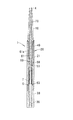
カートリッジ式化粧料容器101は、カートリッジ体2が取り付けられて用いられるものである。カートリッジ式化粧料容器101は、図12に示すように、カートリッジ体2が着脱自在に取り付けられる本体筒120と、本体筒120に対して同軸に、かつ相対回転可能に取り付けられる駆動体130と、押棒60と、雌ねじ53が内周に形成される雌ねじ部材150と、雌ねじ部材150及び押棒60を付勢する付勢部材としてのコイルばね107とを備える。本体筒120は、駆動体130が相対回転可能に取り付けられる本体外筒121と、本体外筒121の内周に挿入される本体内筒40とを備える。 The cartridge type cosmetic container 101 is used with the cartridge body 2 attached thereto. As shown in FIG. 12, the cartridge-type cosmetic container 101 includes a main body cylinder 120 to which the cartridge body 2 is detachably attached, a drive body 130 attached coaxially to the main body cylinder 120 and relatively rotatable, A push rod 60, a female screw member 150 in which the female screw portion 53 is formed on the inner periphery, and a coil spring 107 as a biasing member that biases the female screw member 150 and the push rod 60 are provided. The main body cylinder 120 includes a main body outer cylinder 121 to which the driving body 130 is attached so as to be relatively rotatable, and a main body inner cylinder 40 inserted into the inner periphery of the main body outer cylinder 121.

また、カートリッジ式化粧料容器101は、本体筒120と駆動体130との相対回転を一方向にのみ許容するラチェット機構180を更に備える。ラチェット機構180は、本体外筒121の内周に形成されるラチェット溝24と、本体外筒121に相対回転可能に収容されるラチェット部材80と、を有する。化粧料4を繰り出すための各部品は、カートリッジ式化粧料容器101に集約されている。   The cartridge-type cosmetic container 101 further includes a ratchet mechanism 180 that allows relative rotation between the main body cylinder 120 and the driving body 130 in only one direction. The ratchet mechanism 180 includes a ratchet groove 24 formed on the inner periphery of the main body outer cylinder 121 and a ratchet member 80 accommodated in the main body outer cylinder 121 so as to be relatively rotatable. Each part for paying out the cosmetic 4 is collected in a cartridge-type cosmetic container 101.

カートリッジ体2、押棒60及び本体内筒40の構造は、第1の実施形態におけるカートリッジ体2、押棒60及び本体内筒40の構造と同じであるので、ここではその説明を省略する。   Since the structures of the cartridge body 2, the push rod 60, and the main body inner cylinder 40 are the same as the structures of the cartridge body 2, the push bar 60, and the main body inner cylinder 40 in the first embodiment, the description thereof is omitted here.

図14から図19を参照して、カートリッジ式化粧料容器101について説明する。   The cartridge type cosmetic container 101 will be described with reference to FIGS.

図14及び図15に示すように、本体外筒121は、前端開口22と後端開口29とを有する略円筒状に形成される。前端開口22の近傍の内周に、環状の嵌合凹部23が形成される。後端開口29の近傍の内周に、嵌合凹部28が形成される。本体外筒121の内周には、近接ガイド部25とガイド壁部26とが形成される。 As shown in FIGS. 14 and 15, the main body outer cylinder 121 is formed in a substantially cylindrical shape having a front end opening 22 and a rear end opening 29. An annular fitting recess 23 is formed on the inner periphery in the vicinity of the front end opening 22. A fitting recess 28 is formed on the inner periphery in the vicinity of the rear end opening 29. A proximity guide portion 25 and a guide wall portion 26 are formed on the inner periphery of the main body outer cylinder 121 .

本体外筒121の内周には、複数のラチェット溝24が形成される。ラチェット溝24は、近接ガイド部25から後端開口29に向けて軸方向に延在する。   A plurality of ratchet grooves 24 are formed on the inner periphery of the main body outer cylinder 121. The ratchet groove 24 extends in the axial direction from the proximity guide portion 25 toward the rear end opening 29.

図14及び図16に示すように、駆動体130は、有底の略円筒状に形成される。駆動体130は、本体外筒121に嵌入される嵌入部131と、嵌入部131に連続して形成される摘み部32と、を有する。嵌入部131は、略円筒状に形成される。嵌入部131の外周には、嵌合凸部34とOリング溝33とが形成される。   As shown in FIGS. 14 and 16, the driving body 130 is formed in a substantially cylindrical shape with a bottom. The driving body 130 includes an insertion portion 131 that is inserted into the main body outer cylinder 121, and a knob portion 32 that is formed continuously with the insertion portion 131. The fitting part 131 is formed in a substantially cylindrical shape. A fitting convex part 34 and an O-ring groove 33 are formed on the outer periphery of the fitting part 131.

また、駆動体130は、押棒60の大径部63のリブ63bに係合する複数の溝135と、支柱36と、が設けられる。溝135は、駆動体130の内周に、駆動体130の内周の底面37から前端開口139まで軸方向に延在する。溝135と押棒60の大径部63のリブ63bとの係合により、押棒60と駆動体130との相対回転が不能になる。   In addition, the drive body 130 is provided with a plurality of grooves 135 that engage with the ribs 63 b of the large-diameter portion 63 of the push rod 60 and the columns 36. The groove 135 extends in the axial direction from the bottom surface 37 of the inner periphery of the driving body 130 to the front end opening 139 on the inner periphery of the driving body 130. Due to the engagement between the groove 135 and the rib 63b of the large-diameter portion 63 of the push rod 60, relative rotation between the push rod 60 and the driving body 130 becomes impossible.

前端開口139の近傍の溝135の内面には、突部38が形成される。突部38を、ラチェット部材80の後述する突部85が乗り越える。   A protrusion 38 is formed on the inner surface of the groove 135 near the front end opening 139. A protrusion 85 (described later) of the ratchet member 80 gets over the protrusion 38.

図14及び図17に示すように、コイルばね107は、棒軸61がコイルばね107の内周を挿通するようにコイルばね載置部63aとラチェット部材80との間に配置される。コイルばね107の自由長は、繰出下降限に位置する押棒60のコイルばね載置部63aとラチェット部材80との間の距離よりも長い。そのため、カートリッジ式化粧料容器101が組み立てられた状態では、コイルばね107は、大径部63とラチェット部材80とを互いに離す方向に押棒60とラチェット部材80とを付勢する。   As shown in FIGS. 14 and 17, the coil spring 107 is disposed between the coil spring mounting portion 63 a and the ratchet member 80 so that the rod shaft 61 passes through the inner periphery of the coil spring 107. The free length of the coil spring 107 is longer than the distance between the coil spring placement portion 63a of the push rod 60 located at the feeding lower limit and the ratchet member 80. Therefore, in a state where the cartridge type cosmetic container 101 is assembled, the coil spring 107 biases the push rod 60 and the ratchet member 80 in a direction in which the large diameter portion 63 and the ratchet member 80 are separated from each other.

図14及び図18に示すように、雌ねじ部材150は、本体部51と、押棒60が挿通する孔152aを有する挿通部152と、を有する。挿通部152の一部は、本体部51から軸方向に連続して形成される。   As shown in FIGS. 14 and 18, the female screw member 150 includes a main body 51 and an insertion portion 152 having a hole 152 a through which the push rod 60 is inserted. A part of the insertion part 152 is formed continuously from the main body part 51 in the axial direction.

雌ねじ部材150の後端面(挿通部152の後端面)50bには、コイルばね107の付勢力がラチェット部材80を介して作用する。コイルばね107の付勢力が後端面50bに作用することにより、雌ねじ部材150は、押棒60の大径部63から離間する方向に付勢される。   The biasing force of the coil spring 107 acts on the rear end surface (rear end surface of the insertion portion 152) 50b of the female screw member 150 via the ratchet member 80. When the biasing force of the coil spring 107 acts on the rear end surface 50 b, the female screw member 150 is biased in a direction away from the large-diameter portion 63 of the push rod 60.

雌ねじ部材150の後端面50bは環状に形成される。そのため、コイルばね107の付勢力は、偏りなく雌ねじ部材150に作用する。したがって、雌ねじ部材150が軸方向に対して傾くのを防ぐことができる。   The rear end surface 50b of the female screw member 150 is formed in an annular shape. Therefore, the biasing force of the coil spring 107 acts on the female screw member 150 without deviation. Therefore, it is possible to prevent the female screw member 150 from being inclined with respect to the axial direction.

挿通部152の孔152aは、断面が略楕円形状を有し、かつ略楕円形状の長軸が延在部51bの外側面56bに沿うように形成される。したがって、孔152aに棒軸61が挿通された状態でも、雌ねじ部材150は、径方向へ移動可能である。   The hole 152a of the insertion portion 152 is formed such that the cross section has a substantially elliptical shape and the major axis of the substantially elliptical shape is along the outer surface 56b of the extending portion 51b. Therefore, the female screw member 150 can move in the radial direction even when the rod shaft 61 is inserted through the hole 152a.

図14及び図19に示すように、ラチェット部材80は、本体外筒121の内周に収容される本体部81と、駆動体130に嵌入される嵌入部82と、を有する。嵌入部82は、略円柱状に、本体部81から軸方向に連続して形成される。   As shown in FIGS. 14 and 19, the ratchet member 80 has a main body portion 81 accommodated in the inner periphery of the main body outer cylinder 121 and a fitting portion 82 fitted into the driving body 130. The fitting portion 82 is formed in a substantially cylindrical shape continuously from the main body portion 81 in the axial direction.

嵌入部82の外周には、本体部81から後端面80bまで軸方向に延在する複数のリブ84と、リブ84の先端に突出して形成される突部85と、が設けられる。   A plurality of ribs 84 extending in the axial direction from the main body 81 to the rear end face 80 b and a protrusion 85 formed to protrude from the tip of the rib 84 are provided on the outer periphery of the fitting portion 82.

リブ84は、駆動体130の溝135(図16参照)と摺動可能に係合し、駆動体130とラチェット部材80との相対回転を不能にする。よって、使用者が駆動体130を摘んで回転させると、ラチェット部材80は、駆動体130と同期して回転する。リブ84は、軸方向に延在する溝135に係合するので、駆動体130に対するラチェット部材80の軸方向への移動を拘束しない。   The rib 84 is slidably engaged with the groove 135 (see FIG. 16) of the driving body 130, and the relative rotation between the driving body 130 and the ratchet member 80 is disabled. Therefore, when the user picks and rotates the driving body 130, the ratchet member 80 rotates in synchronization with the driving body 130. Since the rib 84 engages with the groove 135 extending in the axial direction, the movement of the ratchet member 80 in the axial direction relative to the drive body 130 is not restricted.

突部85は、嵌入部82が駆動体130に挿入された状態では、駆動体130の突部38に対して駆動体130の前端開口139とは反対側に位置する。したがって、ラチェット部材80が駆動体130から抜ける方向に移動すると、ラチェット部材80の突部85は、駆動体130の突部38を係止して、駆動体130からラチェット部材80が抜けるのを防止する。   The protrusion 85 is located on the side opposite to the front end opening 139 of the drive body 130 with respect to the protrusion 38 of the drive body 130 in a state where the fitting portion 82 is inserted into the drive body 130. Therefore, when the ratchet member 80 moves in the direction in which the ratchet member 80 is removed, the protrusion 85 of the ratchet member 80 engages the protrusion 38 of the driver 130 to prevent the ratchet member 80 from being released from the driver 130. To do.

本体部81は、円筒形状の側面に、2つの略U字状のスリット83a,83bを軸方向に対して90度回転させ周方向に並べて形成した形状を有する。略U字状の各スリット83a,83bの内側(各スリット83a,83bにおける周方向に延在する2つの部分の間)には、断面が弧状に延在する支持部81aが形成される。支持部81aは、周方向の一端部において嵌入部82に対して固定される。したがって、支持部81の他端部に径方向の力が作用すると、支持部81aは一端部を支点に径方向に撓む。   The main body 81 has a shape in which two substantially U-shaped slits 83a and 83b are rotated 90 degrees with respect to the axial direction and arranged in the circumferential direction on a cylindrical side surface. Inside the substantially U-shaped slits 83a and 83b (between the two portions extending in the circumferential direction of the slits 83a and 83b), a support portion 81a whose cross section extends in an arc shape is formed. The support portion 81a is fixed to the insertion portion 82 at one end portion in the circumferential direction. Therefore, when a radial force acts on the other end portion of the support portion 81, the support portion 81a bends in the radial direction with the one end portion as a fulcrum.

各支持部81aの他端部には、径方向外側に突出するラチェット歯81bが設けられる。支持部81aが径方向に撓むことにより、ラチェット歯81bは径方向に移動する。径方向内側の力が支持部81aの他端部に作用しなくなると、支持部81aは元の形状に戻り、ラチェット歯81bが元の位置に戻る。   Ratchet teeth 81b projecting radially outward are provided at the other end of each support portion 81a. As the support portion 81a is bent in the radial direction, the ratchet teeth 81b move in the radial direction. When the radially inner force no longer acts on the other end of the support portion 81a, the support portion 81a returns to its original shape, and the ratchet teeth 81b return to their original positions.

ラチェット歯81bは、ラチェット部材80と本体外筒121との相対回転を一方向にのみ許容するように、本体外筒121のラチェット溝24と係合する。以下において、相対回転が許容される方向を、「回転許容方向」と称し、相対回転が拘束される方向を、「回転拘束方向」と称す。   The ratchet teeth 81b engage with the ratchet groove 24 of the main body outer cylinder 121 so as to allow relative rotation between the ratchet member 80 and the main body outer cylinder 121 only in one direction. Hereinafter, a direction in which relative rotation is allowed is referred to as a “rotation allowable direction”, and a direction in which relative rotation is restricted is referred to as a “rotation restricted direction”.

ラチェット歯81bと本体外筒121のラチェット溝24との係合をより具体的に説明する。   The engagement between the ratchet teeth 81b and the ratchet groove 24 of the main body outer cylinder 121 will be described more specifically.

ラチェット部材80を本体外筒121に対して回転許容方向に回転させようとすると、ラチェット歯81bの傾斜面がラチェット溝24の傾斜面から径方向内側の力を受け、支持部81aが径方向内側に撓む。支持部81aの撓みにより、ラチェット歯81bが径方向内側に移動し、ラチェット歯81bの傾斜面がラチェット溝24の傾斜面を乗り越える。その結果、回転許容方向への回転が許容される。 When the ratchet member 80 is rotated in the rotation allowable direction with respect to the main body outer cylinder 121, the inclined surface of the ratchet tooth 81b receives a radially inner force from the inclined surface of the ratchet groove 24 , and the support portion 81a is radially inward. Bend. Due to the bending of the support portion 81a , the ratchet teeth 81b move inward in the radial direction, and the inclined surface of the ratchet teeth 81b gets over the inclined surface of the ratchet groove 24. As a result, rotation in the rotation allowable direction is allowed.

ラチェット部材80を本体外筒121に対して回転拘束方向に回転させようとすると、ラチェット歯81bの垂直面がラチェット溝24の垂直面に当たる。これによって、回転拘束方向への回転が阻止される。   When the ratchet member 80 is rotated in the rotation restraining direction with respect to the main body outer cylinder 121, the vertical surface of the ratchet teeth 81 b hits the vertical surface of the ratchet groove 24. As a result, rotation in the rotation restraining direction is prevented.

このように、ラチェット歯81bは、ラチェット部材80と本体外筒121との相対回転を一方向にのみ許容するように、本体外筒121のラチェット溝24と係合する。ラチェット溝24は軸方向に延在するので、軸方向へのラチェット部材80の移動は、ラチェット歯81bとラチェット溝24との係合により拘束されない。   In this manner, the ratchet teeth 81b engage with the ratchet groove 24 of the main body outer cylinder 121 so as to allow relative rotation between the ratchet member 80 and the main body outer cylinder 121 only in one direction. Since the ratchet groove 24 extends in the axial direction, the movement of the ratchet member 80 in the axial direction is not restricted by the engagement between the ratchet teeth 81 b and the ratchet groove 24.

カートリッジ式化粧料容器101では、回転許容方向は、押棒60を繰り出すように本体筒120と駆動体130(ラチェット部材80)とを相対回転させる方向であり、回転拘束方向は、押棒60を繰り戻すように本体筒120と駆動体130とを相対回転させる方向である。そのため、使用者が押棒60を繰り戻す方向へ本体筒120と駆動体130とを相対回転させようとしても、本体筒120と駆動体130とは相対回転しない。したがって、誤操作による化粧料4の繰り戻しを防止することができる。   In the cartridge-type cosmetic container 101, the rotation allowable direction is a direction in which the main body cylinder 120 and the driving body 130 (the ratchet member 80) are relatively rotated so that the push bar 60 is drawn out, and the rotation restraint direction is a direction in which the push bar 60 is fed back. In this way, the main body cylinder 120 and the driving body 130 are relatively rotated. Therefore, even if the user tries to relatively rotate the main body cylinder 120 and the driving body 130 in the direction in which the push rod 60 is moved back, the main body cylinder 120 and the driving body 130 do not relatively rotate. Therefore, it is possible to prevent the cosmetic 4 from being fed back due to an erroneous operation.

ラチェット部材80の前端面(本体部81の前端面)80aは、雌ねじ部材150の後端面50bに当接する。ラチェット部材80の後端面(嵌入部82の後端面)80bには、コイルばね107が当接する。つまり、コイルばね107の付勢力は、ラチェット部材80を介して雌ねじ部材150に作用する。 A front end surface of the ratchet member 80 (a front end surface of the main body portion 81) 80a abuts on the rear end surface 50b of the female screw member 150 . The coil spring 107 is in contact with the rear end surface (rear end surface of the fitting portion 82) 80b of the ratchet member 80. That is, the biasing force of the coil spring 107 acts on the female screw member 150 via the ratchet member 80.

ラチェット部材80は、カートリッジ外筒10が本体筒120に取り付けられるときに、コイルばね107を圧縮して収縮させながらカートリッジ外筒10及び雌ねじ部材150とともに移動する。ラチェット部材80は、カートリッジ外筒10が本体筒120から取り外されるときに、コイルばね107の付勢力によって、カートリッジ外筒10及び雌ねじ部材150とともに移動する。 The ratchet member 80 moves together with the cartridge outer cylinder 10 and the female screw member 150 while compressing and contracting the coil spring 107 when the cartridge outer cylinder 10 is attached to the main body cylinder 120. The ratchet member 80 moves together with the cartridge outer cylinder 10 and the female screw member 150 by the biasing force of the coil spring 107 when the cartridge outer cylinder 10 is removed from the main body cylinder 120.

ラチェット部材80は、本体外筒121の内周に配置されるとともに、駆動体130の嵌入部131と雌ねじ部材150との間に配置される。   The ratchet member 80 is disposed on the inner periphery of the main body outer cylinder 121 and is disposed between the fitting portion 131 of the driving body 130 and the female screw member 150.

本体外筒121の近接ガイド部25から後端開口29までの領域における内径は、本体外筒21の対応する領域における内径と比べて小さい。これにより、ラチェット溝24の深さを確保することができる。   The inner diameter in the region from the proximity guide portion 25 of the main body outer cylinder 121 to the rear end opening 29 is smaller than the inner diameter in the corresponding region of the main body outer cylinder 21. Thereby, the depth of the ratchet groove 24 can be ensured.

駆動体130の嵌入部131は、駆動体30の嵌入部31と比べて短く形成される。また、雌ねじ部材150の挿通部152は、雌ねじ部材50の挿通部52と比べて短く形成される。さらに、コイルばね107の自由長は、コイルばね7の自由長と比べて短い。そのため、雌ねじ部材150の雌ねじ部53から駆動体130の底面37までの寸法は、第1の実施形態におけるカートリッジ式化粧料容器の対応する寸法と略等しい。したがって、第1の実施形態で用いた押棒60を本実施形態でも用いることができる。 The insertion part 131 of the driving body 130 is formed shorter than the insertion part 31 of the driving body 30. Further, the insertion portion 152 of the female screw member 150 is formed shorter than the insertion portion 52 of the female screw member 50. Furthermore, the free length of the coil spring 107 is shorter than the free length of the coil spring 7. Therefore, the dimension from the internal thread part 53 of the internal thread member 150 to the bottom surface 37 of the drive body 130 is substantially equal to the corresponding dimension of the cartridge type cosmetic container in the first embodiment. Therefore, the push rod 60 used in the first embodiment can also be used in this embodiment.

以下、図12から図19を参照して、カートリッジ式化粧料容器101の組み立て手順について説明する。カートリッジ体2の組み立て手順については、第1の実施形態と同じであるため、ここではその説明を省略する。   Hereinafter, the assembly procedure of the cartridge type cosmetic container 101 will be described with reference to FIGS. Since the assembly procedure of the cartridge body 2 is the same as that of the first embodiment, the description thereof is omitted here.

カートリッジ式化粧料容器101の組み立て手順について説明する。   A procedure for assembling the cartridge type cosmetic container 101 will be described.

まず、第1の実施形態と同様に、本体内筒40に雌ねじ部材150を組み付け、雌ねじ部材150が組み付けられた本体内筒40を本体外筒121に組み付ける。   First, as in the first embodiment, the female thread member 150 is assembled to the main body inner cylinder 40, and the main body inner cylinder 40 assembled with the female screw member 150 is assembled to the main body outer cylinder 121.

次に、押棒60をコイルばね107の内周に押棒60の天面62側から挿入し、コイルばね107を押棒60のコイルばね載置部63aに載置する。その後、押棒60の腔部64に駆動体130の支柱36が挿入されるように、押棒60を駆動体130の内周に挿入する。このとき、大径部63のリブ63bと駆動体130の溝135とを係合させる。   Next, the push rod 60 is inserted into the inner periphery of the coil spring 107 from the top surface 62 side of the push rod 60, and the coil spring 107 is placed on the coil spring placement portion 63 a of the push rod 60. Thereafter, the push rod 60 is inserted into the inner periphery of the drive body 130 so that the column 36 of the drive body 130 is inserted into the cavity 64 of the push rod 60. At this time, the rib 63b of the large diameter portion 63 and the groove 135 of the driving body 130 are engaged.

次に、押棒60の天面62をラチェット部材80の後端開口86に通し、押棒60をラチェット部材80に挿入する。ラチェット部材80に押棒60が挿入された状態で、ラチェット部材80の後端面80bを駆動体130の前端開口139に通し、ラチェット部材80の嵌入部82を駆動体130に挿入する。   Next, the top surface 62 of the push rod 60 is passed through the rear end opening 86 of the ratchet member 80, and the push rod 60 is inserted into the ratchet member 80. With the push rod 60 inserted into the ratchet member 80, the rear end surface 80 b of the ratchet member 80 is passed through the front end opening 139 of the drive body 130, and the fitting portion 82 of the ratchet member 80 is inserted into the drive body 130.

ラチェット部材80の突部85が、駆動体130の突部38を乗り越えるまでラチェット部材80を駆動体130に挿入すると、突部85と突部38との係止により、ラチェット部材80が駆動体130から抜けにくくなる。これにより、コイルばね107が押棒60のコイルばね載置部63aとラチェット部材80の後端面80bとの間に挟まれ、コイルばね107が駆動体130から飛び出すのを防止することができる。   When the ratchet member 80 is inserted into the driving body 130 until the protruding portion 85 of the ratchet member 80 gets over the protruding portion 38 of the driving body 130, the ratchet member 80 is engaged with the driving body 130 by the locking of the protruding portion 85 and the protruding portion 38. It becomes difficult to come off. As a result, the coil spring 107 is sandwiched between the coil spring placement portion 63 a of the push rod 60 and the rear end surface 80 b of the ratchet member 80, and the coil spring 107 can be prevented from jumping out of the drive body 130.

次に、本体外筒121の後端開口29に押棒60の天面62及びラチェット部材80の前端面80aを通し、押棒60及びラチェット部材80を本体外筒121の内周に挿入する。さらに、本体外筒121の後端開口29に駆動体130の先端を通し、本体外筒121のラチェット溝24とラチェット部材80のラチェット歯81bを係合させながら、駆動体130の嵌入部131を本体外筒121の内周に挿入する。駆動体130の嵌合凸部34と本体外筒121の嵌合凹部28とが嵌合することにより、駆動体130が本体外筒121に組み付けられる。   Next, the top surface 62 of the push rod 60 and the front end surface 80 a of the ratchet member 80 are passed through the rear end opening 29 of the main body outer tube 121, and the push rod 60 and the ratchet member 80 are inserted into the inner periphery of the main body outer tube 121. Further, the front end of the driving body 130 is passed through the rear end opening 29 of the main body outer cylinder 121, and the fitting portion 131 of the driving body 130 is inserted while engaging the ratchet groove 24 of the main body outer cylinder 121 and the ratchet teeth 81 b of the ratchet member 80. It is inserted into the inner periphery of the main body outer cylinder 121. When the fitting convex part 34 of the driving body 130 and the fitting concave part 28 of the main body outer cylinder 121 are fitted, the driving body 130 is assembled to the main body outer cylinder 121.

このとき、カートリッジ式化粧料容器1にはカートリッジ体2が取り付けられていないので、押棒60は、繰出下降限に位置する状態で、本体筒120及び駆動体130の内周に収容される。   At this time, since the cartridge body 2 is not attached to the cartridge-type cosmetic container 1, the push rod 60 is accommodated in the inner periphery of the main body cylinder 120 and the drive body 130 in a state where it is located at the lowering limit.

以上の手順により、カートリッジ式化粧料容器101が完成する。   The cartridge type cosmetic container 101 is completed by the above procedure.

次に、カートリッジ式化粧料容器101へのカートリッジ体2の取り付け手順について説明する。   Next, a procedure for attaching the cartridge body 2 to the cartridge type cosmetic container 101 will be described.

カートリッジ外筒10の雄ねじ15を本体内筒40の雌ねじ43に螺合させながらカートリッジ外筒10の嵌入部19を本体内筒40の内周に挿入すると、カートリッジ外筒10の後端面18が雌ねじ部材150の前端面50aを押し、雌ねじ部材150の後端面50bがラチェット部材80の前端面80aを押す。   When the fitting portion 19 of the cartridge outer cylinder 10 is inserted into the inner periphery of the main body inner cylinder 40 while the male screw 15 of the cartridge outer cylinder 10 is screwed into the female screw 43 of the main body inner cylinder 40, the rear end surface 18 of the cartridge outer cylinder 10 is connected to the female screw. The front end face 50 a of the member 150 is pushed, and the rear end face 50 b of the female screw member 150 pushes the front end face 80 a of the ratchet member 80.

ラチェット部材80は、コイルばね107を圧縮して収縮させながら軸方向に移動する。その結果、雌ねじ部材150は軸方向に移動する。   The ratchet member 80 moves in the axial direction while compressing and contracting the coil spring 107. As a result, the female screw member 150 moves in the axial direction.

雌ねじ部材150の移動により、雌ねじ部材150の羽根部55の前端面55aが本体内筒40の離間ガイド部44の傾斜面44aから離間するとともに、羽根部55の後端面55bが本体外筒121の近接ガイド部25の傾斜面25aに接する。近接ガイド部25は、雌ねじ部材150の雌ねじ部53が雄ねじ61aに近接する方向に雌ねじ部材150を案内するので、雌ねじ部53と雄ねじ61aとが螺合する。   Due to the movement of the female screw member 150, the front end surface 55 a of the blade portion 55 of the female screw member 150 is separated from the inclined surface 44 a of the separation guide portion 44 of the main body inner tube 40, and the rear end surface 55 b of the blade portion 55 is It contacts the inclined surface 25a of the proximity guide portion 25. The proximity guide portion 25 guides the female screw member 150 in a direction in which the female screw portion 53 of the female screw member 150 approaches the male screw 61a, so that the female screw portion 53 and the male screw 61a are screwed together.

以上により、カートリッジ式化粧料容器101へのカートリッジ体2の取り付けが完了する。   Thus, the attachment of the cartridge body 2 to the cartridge type cosmetic container 101 is completed.

次に、カートリッジ式化粧料容器101からのカートリッジ体2の取り外し手順について説明する。   Next, a procedure for removing the cartridge body 2 from the cartridge type cosmetic container 101 will be described.

まず、カートリッジ外筒10の雄ねじ15と本体内筒40の雌ねじ43との螺合を解除するように、カートリッジ外筒10と本体筒120とを相対回転させる。カートリッジ外筒10と本体筒120との相対回転により、カートリッジ体2が本体筒120から離間する。このとき、雌ねじ部材150は、コイルばね107により付勢されたラチェット部材80により押され、カートリッジ体2とともに軸方向に移動する。   First, the cartridge outer cylinder 10 and the main body cylinder 120 are relatively rotated so that the male screw 15 of the cartridge outer cylinder 10 and the female screw 43 of the main body inner cylinder 40 are disengaged. The cartridge body 2 is separated from the main body cylinder 120 by the relative rotation between the cartridge outer cylinder 10 and the main body cylinder 120. At this time, the female screw member 150 is pushed by the ratchet member 80 biased by the coil spring 107 and moves in the axial direction together with the cartridge body 2.

雌ねじ部材150がコイルばね7の付勢力により軸方向に移動すると、雌ねじ部材150の羽根部55の後端面55bが本体外筒121の近接ガイド部25の傾斜面25aから離間し、雌ねじ部材150の羽根部55の前端面55aが本体内筒40の離間ガイド部44の傾斜面44aに接する。離間ガイド部44は、雌ねじ部材150の雌ねじ部53が雄ねじ61aから離間する方向に雌ねじ部材150を案内するので、雌ねじ部53と雄ねじ61aとの螺合が解除される。   When the female screw member 150 is moved in the axial direction by the biasing force of the coil spring 7, the rear end surface 55 b of the blade portion 55 of the female screw member 150 is separated from the inclined surface 25 a of the proximity guide portion 25 of the main body outer cylinder 121. The front end surface 55 a of the blade portion 55 is in contact with the inclined surface 44 a of the separation guide portion 44 of the main body inner cylinder 40. The separation guide portion 44 guides the female screw member 150 in a direction in which the female screw portion 53 of the female screw member 150 is separated from the male screw 61a, so that the screwing of the female screw portion 53 and the male screw 61a is released.

雌ねじ部53と雄ねじ61aとの螺合が解除されると、押棒60は、コイルばね107の付勢力により、本体筒120から離間する方向に移動し、繰出下降限に達する。したがって、カートリッジ式化粧料容器101は、押棒60が繰出下降限に位置する状態に戻る。   When the screwing of the female screw portion 53 and the male screw 61a is released, the push rod 60 moves in a direction away from the main body cylinder 120 by the urging force of the coil spring 107, and reaches the feeding lower limit. Therefore, the cartridge-type cosmetic container 101 returns to the state where the push bar 60 is located at the delivery lowering limit.

以上により、カートリッジ式化粧料容器101からのカートリッジ体2の取り外しが完了する。   Thus, the removal of the cartridge body 2 from the cartridge type cosmetic container 101 is completed.

以上の第2の実施形態によれば、第1の実施形態と同様の効果を奏するとともに、誤操作による化粧料4の繰り戻しを防止することができる。   According to the above 2nd Embodiment, while having the same effect as 1st Embodiment, it is possible to prevent the cosmetic 4 from being fed back due to an erroneous operation.

(第3の実施形態)
以下、図20から図22を参照して、本発明の第3の実施形態について説明する。本実施形態に係るカートリッジ式化粧料容器は、第1及び第2の実施形態に係るカートリッジ式化粧料容器1,101と同じであり、カートリッジ式化粧料容器に取り付けられるカートリッジ体102、202、302が第1の実施形態に係るカートリッジ体2と異なる。以下では、カートリッジ体102、202、302について説明する。
(Third embodiment)
Hereinafter, a third embodiment of the present invention will be described with reference to FIGS. The cartridge type cosmetic container according to the present embodiment is the same as the cartridge type cosmetic containers 1 and 101 according to the first and second embodiments, and the cartridge bodies 102, 202, and 302 attached to the cartridge type cosmetic container. Is different from the cartridge body 2 according to the first embodiment. Hereinafter, the cartridge bodies 102, 202, and 302 will be described.

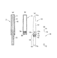
図20に示すように、カートリッジ体102は、貫通孔117を有するカートリッジ外筒110と、貫通孔117に挿入される保持部材170と、キャップ3(図3参照)を備える。カートリッジ外筒110は、化粧料を収容する略円筒状の化粧料収容部112を有する。   As shown in FIG. 20, the cartridge body 102 includes a cartridge outer cylinder 110 having a through hole 117, a holding member 170 inserted into the through hole 117, and a cap 3 (see FIG. 3). The cartridge outer cylinder 110 includes a substantially cylindrical cosmetic container 112 that stores cosmetics.

カートリッジ外筒110の内周には、後端面18から段部17cまで軸方向に延在するローレット117bが形成される。保持部材170の後端には大径部113が設けられる。大径部113の外周には、軸方向に延在しローレット117bと係合するリブ174が形成される。   A knurled 117 b extending in the axial direction from the rear end surface 18 to the stepped portion 17 c is formed on the inner periphery of the cartridge outer cylinder 110. A large diameter portion 113 is provided at the rear end of the holding member 170. On the outer periphery of the large-diameter portion 113, a rib 174 that extends in the axial direction and engages with the knurl 117b is formed.

リブ174がローレット117bに係合することにより、カートリッジ外筒110と保持部材170との相対回転が規制される。つまり、リブ174とローレット117bとにより、カートリッジ外筒110と保持部材170との相対回転を規制する回転規制機構が形成される。そのため、保持部材170の後端面72に当接する押棒60が回転しても、保持部材170はカートリッジ外筒110に対して回転しない。したがって、化粧料収容部112に収容された化粧料が天面71の回転力を受けることなく、化粧料が回転するのを防ぐことができる。   When the rib 174 is engaged with the knurled 117b, the relative rotation between the cartridge outer cylinder 110 and the holding member 170 is restricted. In other words, the rib 174 and the knurled 117 b form a rotation restricting mechanism that restricts relative rotation between the cartridge outer cylinder 110 and the holding member 170. Therefore, even if the push rod 60 that contacts the rear end surface 72 of the holding member 170 rotates, the holding member 170 does not rotate with respect to the cartridge outer cylinder 110. Therefore, the cosmetics stored in the cosmetic storage unit 112 can be prevented from rotating without receiving the rotational force of the top surface 71.

カートリッジ体102の組み立て手順については、第1の実施形態に係るカートリッジ体2の組み立て手順と略同じであるため、ここではその説明を省略する。   Since the assembly procedure of the cartridge body 102 is substantially the same as the assembly procedure of the cartridge body 2 according to the first embodiment, the description thereof is omitted here.

図21に示すように、カートリッジ体202は、カートリッジ外筒210と、カートリッジ外筒210に挿入される保持部材270と、カートリッジ外筒210の先端に取り付けられる筆部材220と、キャップ3(図3参照)を備える。カートリッジ外筒210の内部には、液状の化粧料を貯蔵する貯蔵部217が保持部材270と筆部材220とにより形成される。   As shown in FIG. 21, the cartridge body 202 includes a cartridge outer cylinder 210, a holding member 270 inserted into the cartridge outer cylinder 210, a brush member 220 attached to the tip of the cartridge outer cylinder 210, and a cap 3 (FIG. 3). See). Inside the cartridge outer cylinder 210, a storage portion 217 that stores liquid cosmetics is formed by the holding member 270 and the brush member 220.

筆部材220は、複数の糸状の線材を束ねて形成される穂部221と、穂部221を保持する保持部222と、を有する。保持部222の一部がカートリッジ外筒210の内周に嵌入される。   The brush member 220 includes an ear part 221 formed by bundling a plurality of thread-like wires, and a holding part 222 that holds the ear part 221. A part of the holding portion 222 is fitted into the inner periphery of the cartridge outer cylinder 210.

保持部222には、貯蔵部217から穂部221まで延びる貫通孔223が設けられる。押棒60の繰り出しに伴って保持部材270が貯蔵部217を収縮させる方向に移動すると、貯蔵部217内の化粧料が貫通孔223を通じて穂部221に供給される。   The holding part 222 is provided with a through hole 223 extending from the storage part 217 to the ear part 221. When the holding member 270 moves in the direction in which the storage part 217 contracts as the push bar 60 is fed, the cosmetic in the storage part 217 is supplied to the ear part 221 through the through hole 223.

カートリッジ体202の組み立て手順については、第1の実施形態に係るカートリッジ体2の組み立て手順と略同じであるため、ここではその説明を省略する。   Since the assembly procedure of the cartridge body 202 is substantially the same as the assembly procedure of the cartridge body 2 according to the first embodiment, the description thereof is omitted here.

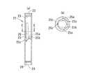
図22に示すように、カートリッジ体302は、カートリッジ外筒310と、カートリッジ外筒310に挿入される保持部材370と、カートリッジ外筒310の内周に収容される付勢部材としてのコイルばね9と、カートリッジ外筒310の後端に取り付けられる尾栓90と、キャップ3(図3参照)と、を備える。   As shown in FIG. 22, the cartridge body 302 includes a cartridge outer cylinder 310, a holding member 370 inserted into the cartridge outer cylinder 310, and a coil spring 9 as an urging member housed on the inner periphery of the cartridge outer cylinder 310. A tail plug 90 attached to the rear end of the cartridge outer cylinder 310, and a cap 3 (see FIG. 3).

保持部材370の前端部には、カップ状の化粧料挿入部371が設けられる。保持部材370の後端部の近傍には、コイルばね9が載置されるコイルばね載置部374が設けられる。保持部材370は、コイルばね9の一端がコイルばね載置部374に当接するように、コイルばね9の内周に挿通される。   A cup-shaped cosmetic material insertion portion 371 is provided at the front end portion of the holding member 370. In the vicinity of the rear end portion of the holding member 370, a coil spring placement portion 374 on which the coil spring 9 is placed is provided. The holding member 370 is inserted through the inner periphery of the coil spring 9 so that one end of the coil spring 9 abuts on the coil spring placement portion 374.

カートリッジ外筒310の貫通孔317は、前端開口11aから形成される第1の孔部317aと、第1の孔部317aから連続して後端開口11bまで形成される第2の孔部317bと、を有する。第2の孔部317bは、第1の孔部317aと比較して大径に形成され、第1の孔部317aと第2の孔部317bとの境に段部317cが形成される。   The through hole 317 of the cartridge outer cylinder 310 includes a first hole 317a formed from the front end opening 11a, and a second hole 317b formed continuously from the first hole 317a to the rear end opening 11b. Have. The second hole 317b has a larger diameter than the first hole 317a, and a step 317c is formed at the boundary between the first hole 317a and the second hole 317b.

コイルばね9の他端は、カートリッジ外筒310の段部317cに当接する。コイルばね9の一端がカートリッジ外筒310に挿入した保持部材370のコイルばね載置部374に当接するので、コイルばね9は、保持部材370のコイルばね載置部374と段部317cとを互いに離間させる方向に保持部材370とカートリッジ外筒310とを付勢する。   The other end of the coil spring 9 abuts on the step 317 c of the cartridge outer cylinder 310. Since one end of the coil spring 9 abuts on the coil spring placement portion 374 of the holding member 370 inserted into the cartridge outer cylinder 310, the coil spring 9 causes the coil spring placement portion 374 and the step portion 317c of the holding member 370 to be connected to each other. The holding member 370 and the cartridge outer cylinder 310 are urged in the separating direction.

保持部材370のコイルばね載置部374は、カートリッジ外筒310の段部317cよりも繰出下降限側に位置する。つまり、コイルばね9は、保持部材370を繰出下降限方向へ付勢する。   The coil spring placement portion 374 of the holding member 370 is positioned on the feeding lower limit side with respect to the step portion 317c of the cartridge outer cylinder 310. That is, the coil spring 9 urges the holding member 370 in the feeding downward limit direction.

尾栓90は、保持部材370がカートリッジ外筒310の後端開口11bから抜けるのを防止する。   The tail plug 90 prevents the holding member 370 from coming out of the rear end opening 11 b of the cartridge outer cylinder 310.

カートリッジ体302では、押棒60の繰り出しに伴って、押棒60の天面62により保持部材70の後端面372が押される。後端面372の押圧により、保持部材370がコイルばね9を圧縮して収縮させながら前端開口11aに向けて移動する。その結果、化粧料挿入部371に挿入された化粧料が前端開口11aから繰り出される。   In the cartridge body 302, the rear end surface 372 of the holding member 70 is pushed by the top surface 62 of the push rod 60 as the push rod 60 is extended. By pressing the rear end surface 372, the holding member 370 moves toward the front end opening 11a while compressing and contracting the coil spring 9. As a result, the cosmetic material inserted into the cosmetic material insertion portion 371 is fed out from the front end opening 11a.

カートリッジ体302が本体筒20,120から取り外されると、押棒60は繰出下降限に移動し、後端面372が押棒60の天面62から離間する。その結果、保持部材370は、コイルばね9の付勢力により、後端開口11bに向けて移動する。尾栓90と保持部材370とが当接すると、保持部材370の移動が停止する。このように、カートリッジ体302では、保持部材370を繰り戻すことができる。   When the cartridge body 302 is removed from the main body cylinders 20 and 120, the push rod 60 moves to the lowering limit, and the rear end surface 372 is separated from the top surface 62 of the push rod 60. As a result, the holding member 370 moves toward the rear end opening 11 b by the biasing force of the coil spring 9. When the tail plug 90 and the holding member 370 come into contact with each other, the movement of the holding member 370 stops. Thus, in the cartridge body 302, the holding member 370 can be moved back.

また、カートリッジ式化粧料容器1(第1の実施形態参照)では、押棒60を繰り戻すように本体筒20と駆動体30とを相対回転させることができる。押棒60が繰り戻されると、コイルばね9の付勢力により、化粧料挿入部371に挿入された化粧料が繰り戻される。つまり、カートリッジ式化粧料容器1にカートリッジ体302を挿着して使用すれば、カートリッジ体302を本体筒20に挿着した状態で、化粧料挿入部371に挿入された化粧料を繰り戻すことができる。   Further, in the cartridge type cosmetic container 1 (see the first embodiment), the main body cylinder 20 and the driving body 30 can be relatively rotated so that the push rod 60 is moved back. When the push rod 60 is moved back, the cosmetic inserted into the cosmetic insert 371 is moved back by the biasing force of the coil spring 9. That is, if the cartridge body 302 is inserted into the cartridge type cosmetic container 1 and used, the cosmetic inserted into the cosmetic insertion portion 371 is fed back with the cartridge body 302 inserted into the main body cylinder 20. Can do.

次に、カートリッジ体302の組み立て手順について説明する。   Next, the assembly procedure of the cartridge body 302 will be described.

まず、保持部材370の化粧料挿入部371側からコイルばね9に保持部材370を挿入し、コイルばね9をコイルばね載置部374に載置する。その後、カートリッジ外筒310の後端開口11bに保持部材370の化粧料挿入部371を通し、保持部材370の後端面372を押して保持部材370及びコイルばね9をカートリッジ外筒310の内周に挿入する。これにより、コイルばね9が、カートリッジ外筒310の段部317cと保持部材370のコイルばね載置部374との間に挟まれる。   First, the holding member 370 is inserted into the coil spring 9 from the cosmetic material insertion portion 371 side of the holding member 370, and the coil spring 9 is placed on the coil spring placement portion 374. Thereafter, the cosmetic material insertion portion 371 of the holding member 370 is passed through the rear end opening 11 b of the cartridge outer cylinder 310, and the rear end surface 372 of the holding member 370 is pushed to insert the holding member 370 and the coil spring 9 into the inner periphery of the cartridge outer cylinder 310. To do. As a result, the coil spring 9 is sandwiched between the step portion 317 c of the cartridge outer cylinder 310 and the coil spring placement portion 374 of the holding member 370.

次に、尾栓90を保持部材370の後端開口11bに通して保持部材370の内周に挿入し、尾栓90の嵌合凸部91とカートリッジ外筒310の嵌合凹部317dとを嵌合する。これにより、尾栓90がカートリッジ外筒310に組み付けられ、カートリッジ外筒310からの保持部材370の抜けが防止される。 Next, the tail plug 90 is inserted into the inner periphery of the holding member 370 through the rear end opening 11b of the holding member 370, and the fitting convex portion 91 of the tail plug 90 and the fitting concave portion 317d of the cartridge outer cylinder 310 are fitted. Match. As a result, the tail plug 90 is assembled to the cartridge outer cylinder 310, and the holding member 370 is prevented from coming off from the cartridge outer cylinder 310.

化粧料の収容、及びキャップ3の取り付けについては、第1実施形態に係るカートリッジ体2と同じであるため、ここではその説明を省略する。   The accommodation of the cosmetic material and the attachment of the cap 3 are the same as those of the cartridge body 2 according to the first embodiment, and thus the description thereof is omitted here.

以上の手順により、カートリッジ体302が完成する。   The cartridge body 302 is completed by the above procedure.

以上の第3の実施形態によれば、第1及び第2の実施形態と同様の効果を奏する。   According to the above 3rd Embodiment, there exists an effect similar to 1st and 2nd embodiment.

また、カートリッジ体102では、保持部材170とカートリッジ外筒110との相対回転が拘束されるので、化粧料収容部112に収容された化粧料が回転するのを防ぎ、化粧料の芯折れを防止することができる。   Further, in the cartridge body 102, since the relative rotation between the holding member 170 and the cartridge outer cylinder 110 is restrained, the cosmetics stored in the cosmetic storage unit 112 are prevented from rotating, and the cosmetics are prevented from being broken. can do.

カートリッジ外筒110は、先端面が軸方向に対して傾斜した化粧料を収容するのに用いられることがある。カートリッジ外筒110の前端面(前端開口111aの周縁)は、軸方向に対して傾斜するため、カートリッジ外筒110はこのような化粧料を収容するのにより好適である。   The cartridge outer cylinder 110 may be used to store cosmetics whose tip surface is inclined with respect to the axial direction. Since the front end surface of the cartridge outer cylinder 110 (periphery of the front end opening 111a) is inclined with respect to the axial direction, the cartridge outer cylinder 110 is more suitable for accommodating such cosmetics.

また、先端面が軸方向に対して傾斜した化粧料は、化粧料の端面の傾斜方向がカートリッジ外筒110に対して一定になるように、回転せずに押し出されることが好ましい。カートリッジ体102では、保持部材170とカートリッジ外筒110との相対回転が拘束されるので、化粧料を回転させずに押し出すことができる。したがって、カートリッジ体102は、先端面が軸方向に対して傾斜した化粧料に対してより好適である。 Also, cosmetic distal end surface is inclined relative to the axial direction, as the inclination direction of the preceding edge of the cosmetic is constant with respect to the cartridge barrel 110 is preferably extruded without rotating. In the cartridge body 102, since the relative rotation between the holding member 170 and the cartridge outer cylinder 110 is restricted, the cosmetic can be pushed out without rotating. Therefore, the cartridge body 102 is more suitable for cosmetics whose tip surface is inclined with respect to the axial direction.

カートリッジ体202では、貯蔵部217がカートリッジ外筒210と保持部材270と筆部材220とにより形成されるので、カートリッジ体202を液状の化粧料に対応させることができる。   In the cartridge body 202, since the storage part 217 is formed by the cartridge outer cylinder 210, the holding member 270, and the brush member 220, the cartridge body 202 can be made to correspond to liquid cosmetics.

カートリッジ体302では、コイルばね9が保持部材370を繰戻方向に付勢するので、カートリッジ式化粧料容器1,101からカートリッジ体302を取り外すだけで、化粧料を繰出下降限まで繰り戻すことができる。   In the cartridge body 302, the coil spring 9 urges the holding member 370 in the retraction direction, so that the cosmetic can be retreated to the delivery lowering limit simply by removing the cartridge body 302 from the cartridge-type cosmetic container 1,101. it can.

また、押棒60を繰り戻し可能なカートリッジ化粧料容器1にカートリッジ体302を挿着して使用すれば、コイルばね9の付勢力により、化粧料挿入部371に挿入された化粧料を繰り戻すことができる。 Further, if the cartridge body 302 is inserted and used in the cartridge type cosmetic container 1 capable of reversing the push bar 60, the cosmetic inserted into the cosmetic insertion portion 371 is fed back by the biasing force of the coil spring 9. be able to.

以上、本発明の実施形態について説明したが、上記実施形態は本発明の適用例の一部を示したに過ぎず、本発明の技術的範囲を上記実施形態の具体的構成に限定する趣旨ではない。   The embodiment of the present invention has been described above. However, the above embodiment only shows a part of application examples of the present invention, and the technical scope of the present invention is limited to the specific configuration of the above embodiment. Absent.

1,101 カートリッジ式化粧料容器
2,102,202,302 カートリッジ体
4 化粧料
7,107 コイルばね(付勢部材)
20,120 本体筒
25 近接ガイド部(第1ガイド部)
30,130 駆動体
44 離間ガイド部(第2ガイド部)
46 突壁部(制限部)
50,150 雌ねじ部材
53 雌ねじ部
60 押棒
61a 雄ねじ
1,101 Cartridge type cosmetic container 2,102,202,302 Cartridge body 4 Cosmetics 7,107 Coil spring (biasing member)
20, 120 Main body cylinder 25 Proximity guide part (first guide part)
30, 130 Driving body 44 Separation guide portion (second guide portion)
46 Projection wall (restricted part)
50,150 Female thread member 53 Female thread part 60 Push rod 61a Male thread

Claims (13)

化粧料が収容されたカートリッジ体が取り付けられて用いられるカートリッジ式化粧料容器であって、
前記カートリッジ体が着脱自在に取り付けられる本体筒と、
前記本体筒に相対回転可能に設けられる駆動体と、
外周に雄ねじが形成され、前記本体筒と前記駆動体との相対回転によって繰り出されて前記カートリッジ体内の化粧料を押し出す押棒と、
前記押棒の外周に設けられる雌ねじ部材と、
前記雌ねじ部材に形成され、前記カートリッジ体が前記本体筒に取り付けられる際に前記雌ねじ部材が前記カートリッジ体によって押圧されることにより、前記雄ねじと螺合する雌ねじ部と、
前記雌ねじ部材を、前記本体筒の前端開口方向に付勢する付勢部材と、を備え、
前記本体筒は、前記雌ねじ部と前記雄ねじとの螺合が解除される方向への前記押棒の移動を制限する制限部を有することを特徴とするカートリッジ式化粧料容器。
A cartridge-type cosmetic container used with a cartridge body containing cosmetics attached thereto,
A main body cylinder to which the cartridge body is detachably attached;
A driving body provided in the main body cylinder so as to be relatively rotatable;
A male bar is formed on the outer periphery, and a push bar that is fed out by relative rotation between the main body cylinder and the driving body to push out cosmetics in the cartridge body,
A female screw member provided on the outer periphery of the push rod;
An internal thread portion that is formed on the internal thread member, and is screwed into the external thread when the internal thread member is pressed by the cartridge body when the cartridge body is attached to the main body cylinder;
An urging member for urging the female screw member in the direction of the front end opening of the main body cylinder;
The cartridge-type cosmetic container characterized in that the main body cylinder has a restricting portion for restricting movement of the push rod in a direction in which the screwing of the female screw portion and the male screw is released.
前記雌ねじ部材は、前記押棒の外周の一部に設けられる本体部を有し、
前記雌ねじ部は、前記本体部に形成され、
前記制限部は、前記雌ねじ部に対向する領域に設けられることを特徴とする請求項1に記載のカートリッジ式化粧料容器。
The female screw member has a main body provided on a part of the outer periphery of the push rod,
The female screw part is formed in the main body part,
The cartridge type cosmetic container according to claim 1, wherein the restriction portion is provided in a region facing the female screw portion.
前記制限部は、前記本体筒の内周面から突出する突壁部であることを特徴とする請求項1又は2に記載のカートリッジ式化粧料容器。   The cartridge type cosmetic container according to claim 1 or 2, wherein the restricting portion is a protruding wall portion protruding from an inner peripheral surface of the main body cylinder. 前記本体筒に設けられ、前記雌ねじ部材が前記カートリッジ体によって押圧された際に前記雌ねじ部と前記雄ねじとが螺合する方向に前記雌ねじ部材を案内する第1ガイド部を更に備えることを特徴とする請求項1から3のいずれか1項に記載のカートリッジ式化粧料容器。   A first guide portion is provided on the main body cylinder and guides the female screw member in a direction in which the female screw portion and the male screw are screwed together when the female screw member is pressed by the cartridge body. The cartridge type cosmetic container according to any one of claims 1 to 3. 前記本体筒に設けられ、前記雌ねじ部材を案内する第2ガイド部を更に備え、
前記第2ガイド部は、前記カートリッジ体による前記雌ねじ部材への押圧が解除された際に前記雌ねじ部と前記雄ねじとの螺合が解除する方向に前記雌ねじ部材を案内することを特徴とする請求項1から4のいずれか1項に記載のカートリッジ式化粧料容器。
A second guide portion provided on the main body cylinder for guiding the female screw member;
The second guide portion guides the female screw member in a direction in which the screwing of the female screw portion and the male screw is released when the pressure on the female screw member by the cartridge body is released. Item 5. The cartridge-type cosmetic container according to any one of Items 1 to 4.
前記本体筒に設けられ、前記雌ねじ部材を案内する第2ガイド部を更に備え、
前記第2ガイド部は、前記カートリッジ体による前記雌ねじ部材への押圧が解除された際に前記雌ねじ部と前記雄ねじとの螺合が解除する方向に前記雌ねじ部材を案内し、
前記本体筒は、本体外筒と、前記本体外筒に収容され前記本体外筒と同期して回転する本体内筒と、を有し、
前記第1ガイド部は、前記本体外筒に設けられ、
前記第2ガイド部は、前記本体内筒に設けられることを特徴とする請求項4に記載のカートリッジ式化粧料容器。
A second guide portion provided on the main body cylinder for guiding the female screw member;
The second guide portion guides the female screw member in a direction in which the screwing of the female screw portion and the male screw is released when the pressure on the female screw member by the cartridge body is released,
The main body cylinder has a main body outer cylinder, and a main body inner cylinder housed in the main body outer cylinder and rotating in synchronization with the main body outer cylinder,
The first guide portion is provided in the main body outer cylinder,
The cartridge-type cosmetic container according to claim 4, wherein the second guide portion is provided on the inner cylinder.
前記付勢部材は、前記押棒を繰出下降限方向に付勢することを特徴とする請求項1から6のいずれか1項に記載のカートリッジ式化粧料容器。   The cartridge-type cosmetic container according to any one of claims 1 to 6, wherein the urging member urges the push bar in a feeding and descending limit direction. 前記雌ねじ部材は、前記押棒が挿通する挿通部を有し、
前記付勢部材の付勢力は、前記挿通部の端面に作用することを特徴とする請求項1から7のいずれか1項に記載のカートリッジ式化粧料容器。
The female screw member has an insertion portion through which the push rod is inserted,
The cartridge type cosmetic container according to any one of claims 1 to 7, wherein an urging force of the urging member acts on an end surface of the insertion portion.
前記本体筒と前記駆動体との相対回転を一方向にのみ許容するラチェット機構を更に備えることを特徴とする請求項1から8のいずれか1項に記載のカートリッジ式化粧料容器。   The cartridge type cosmetic container according to any one of claims 1 to 8, further comprising a ratchet mechanism that allows relative rotation of the main body cylinder and the driving body only in one direction. 前記ラチェット機構は、
前記本体筒の内周に形成され、軸方向に延在するラチェット溝と、
前記ラチェット溝に挿入されるラチェット歯を有し、前記駆動体と同期して回転するラチェット部材と、を有し、
前記付勢手段は、前記ラチェット部材を介して前記雌ねじ部材を付勢することを特徴とする請求項9に記載のカートリッジ式化粧料容器。
The ratchet mechanism is
A ratchet groove formed on the inner circumference of the main body cylinder and extending in the axial direction;
A ratchet member having a ratchet tooth inserted into the ratchet groove, and rotating in synchronization with the drive body;
The cartridge type cosmetic container according to claim 9, wherein the urging unit urges the female screw member via the ratchet member.
前記本体筒に取り付けられる前記カートリッジ体を更に備え、
前記カートリッジ体は、
化粧料が収容される貫通孔を有するカートリッジ外筒と、
前記カートリッジ外筒に移動可能に収容され、化粧料を保持する保持部材と、を有し、
前記保持部材は、前記押棒が繰り出されたときに前記押棒により押圧されて前記カートリッジ体内の化粧料を押し出すことを特徴とする請求項1から10のいずれか1項に記載のカートリッジ式化粧料容器。
The cartridge body further attached to the main body cylinder,
The cartridge body is
A cartridge outer cylinder having a through-hole in which cosmetics are accommodated;
A holding member that is movably accommodated in the cartridge outer cylinder and holds the cosmetic,
The cartridge-type cosmetic container according to any one of claims 1 to 10, wherein the holding member is pressed by the push bar when the push bar is unwound to push out the cosmetic in the cartridge body. .
前記カートリッジ体は、前記カートリッジ外筒と前記保持部材との相対回転を規制する回転規制機構を更に有することを特徴とする請求項11に記載のカートリッジ式化粧料容器。   The cartridge type cosmetic container according to claim 11, wherein the cartridge body further includes a rotation restricting mechanism for restricting relative rotation between the cartridge outer cylinder and the holding member. 前記カートリッジ体は、前記保持部材を繰出下降限方向へ付勢する付勢部材を更に備えることを特徴とする請求項11または12に記載のカートリッジ式化粧料容器。   The cartridge type cosmetic container according to claim 11 or 12, wherein the cartridge body further includes an urging member that urges the holding member in a feeding and descending limit direction.
JP2015157546A 2015-08-07 2015-08-07 Cartridge type cosmetic container Active JP6185964B2 (en)

Priority Applications (4)

Application Number Priority Date Filing Date Title
JP2015157546A JP6185964B2 (en) 2015-08-07 2015-08-07 Cartridge type cosmetic container
US15/748,703 US10542813B2 (en) 2015-08-07 2016-07-29 Cartridge-type cosmetic container
PCT/JP2016/072399 WO2017026305A1 (en) 2015-08-07 2016-07-29 Cartridge-type cosmetic container
EP16835002.3A EP3332667B1 (en) 2015-08-07 2016-07-29 Cartridge-type cosmetic container

Applications Claiming Priority (1)

Application Number Priority Date Filing Date Title
JP2015157546A JP6185964B2 (en) 2015-08-07 2015-08-07 Cartridge type cosmetic container

Publications (3)

Publication Number Publication Date
JP2017035235A JP2017035235A (en) 2017-02-16
JP2017035235A5 JP2017035235A5 (en) 2017-07-06
JP6185964B2 true JP6185964B2 (en) 2017-08-23

Family

ID=57983149

Family Applications (1)

Application Number Title Priority Date Filing Date
JP2015157546A Active JP6185964B2 (en) 2015-08-07 2015-08-07 Cartridge type cosmetic container

Country Status (4)

Country Link
US (1) US10542813B2 (en)
EP (1) EP3332667B1 (en)
JP (1) JP6185964B2 (en)
WO (1) WO2017026305A1 (en)

Families Citing this family (8)

* Cited by examiner, † Cited by third party
Publication number Priority date Publication date Assignee Title
JP6393791B2 (en) * 2017-02-28 2018-09-19 鈴野化成株式会社 Cartridge, cartridge holder, and cartridge-type cosmetic container
FR3077188B1 (en) * 2018-01-29 2020-01-10 L'oreal DEVICE FOR SUPPORTING A COSMETIC ARTICLE
DE202020106678U1 (en) 2020-11-20 2022-02-24 A. W. Faber-Castell COSMETICS GmbH Refillable cosmetic pen
JP2022190935A (en) * 2021-06-15 2022-12-27 株式会社トキワ Rod-like article delivery container
DE202022107014U1 (en) 2022-12-15 2023-01-19 A. W. Faber-Castell COSMETICS GmbH Refillable cosmetic pen
DE202023100351U1 (en) 2023-01-25 2023-02-27 A. W. Faber-Castell COSMETICS GmbH Refillable cosmetic pen
DE202023101272U1 (en) 2023-03-15 2023-03-29 A. W. Faber-Castell COSMETICS GmbH Refillable cosmetic pen
DE202023101260U1 (en) 2023-03-15 2023-03-29 A. W. Faber-Castell COSMETICS GmbH Refillable cosmetic pen

Family Cites Families (4)

* Cited by examiner, † Cited by third party
Publication number Priority date Publication date Assignee Title
JP4560583B1 (en) * 2010-01-18 2010-10-13 鈴野化成株式会社 Cosmetic material supply container
JP6088288B2 (en) * 2013-02-27 2017-03-01 鈴野化成株式会社 Cartridge type cosmetic container
JP5452753B1 (en) * 2013-05-27 2014-03-26 鈴野化成株式会社 Cartridge type cosmetic container
JP6281103B2 (en) * 2013-07-29 2018-02-21 株式会社トキワ Coating material extrusion container

Also Published As

Publication number Publication date
EP3332667B1 (en) 2020-04-08
US20190000216A1 (en) 2019-01-03
US10542813B2 (en) 2020-01-28
EP3332667A1 (en) 2018-06-13
JP2017035235A (en) 2017-02-16
WO2017026305A1 (en) 2017-02-16
EP3332667A4 (en) 2019-04-03

Similar Documents

Publication Publication Date Title
JP6185964B2 (en) Cartridge type cosmetic container
JP6281103B2 (en) Coating material extrusion container
JP2017035235A5 (en)
JP2018102821A (en) Cartridge type cosmetic container
JP6088288B2 (en) Cartridge type cosmetic container
JP6354023B2 (en) Applicator
CN104684437A (en) Cartridge-type cosmetic container
JP4537338B2 (en) Stick cosmetic cartridge
JP2002336042A (en) Bar-shaped cosmetic material container
JP5325593B2 (en) Cartridge type cosmetic container
JP5452753B1 (en) Cartridge type cosmetic container
US20170340088A1 (en) Rod-shaped cosmetic material feeding container
JP6561278B2 (en) Coating material extrusion container
JP2012040230A (en) Cosmetic material delivery container
JP6785492B2 (en) Cosmetic cartridges and cartridge-type cosmetic containers
JP6986247B2 (en) Cartridge type cosmetic container
JP2017136104A (en) Cartridge body and cartridge type cosmetic container
JP3970273B2 (en) Injection-molded cylindrical body, injection-molded cylindrical mold, and injection-molded cylinder manufacturing method
JP4838393B1 (en) Stick-shaped cosmetic material feeding container
CN114828694A (en) Stick-shaped cosmetic container
JP7370677B2 (en) feeding container
JP4620496B2 (en) Bar-shaped cosmetic container and bar-shaped cosmetic supply container
JP6986250B2 (en) Cartridges, cartridge holders, and cartridge-type cosmetic containers
JP2021186655A (en) Delivery container
JP5452688B1 (en) Cartridge type cosmetic container

Legal Events

Date Code Title Description
RD02 Notification of acceptance of power of attorney

Free format text: JAPANESE INTERMEDIATE CODE: A7422

Effective date: 20161205

A521 Request for written amendment filed

Free format text: JAPANESE INTERMEDIATE CODE: A523

Effective date: 20170522

A621 Written request for application examination

Free format text: JAPANESE INTERMEDIATE CODE: A621

Effective date: 20170522

A871 Explanation of circumstances concerning accelerated examination

Free format text: JAPANESE INTERMEDIATE CODE: A871

Effective date: 20170522

TRDD Decision of grant or rejection written
A975 Report on accelerated examination

Free format text: JAPANESE INTERMEDIATE CODE: A971005

Effective date: 20170626

A01 Written decision to grant a patent or to grant a registration (utility model)

Free format text: JAPANESE INTERMEDIATE CODE: A01

Effective date: 20170704

A61 First payment of annual fees (during grant procedure)

Free format text: JAPANESE INTERMEDIATE CODE: A61

Effective date: 20170728

R150 Certificate of patent or registration of utility model

Ref document number: 6185964

Country of ref document: JP

Free format text: JAPANESE INTERMEDIATE CODE: R150

R250 Receipt of annual fees

Free format text: JAPANESE INTERMEDIATE CODE: R250

R250 Receipt of annual fees

Free format text: JAPANESE INTERMEDIATE CODE: R250

R250 Receipt of annual fees

Free format text: JAPANESE INTERMEDIATE CODE: R250

R250 Receipt of annual fees

Free format text: JAPANESE INTERMEDIATE CODE: R250