JP6185944B2 - Game machine - Google Patents
Game machine Download PDFInfo
- Publication number
- JP6185944B2 JP6185944B2 JP2015030625A JP2015030625A JP6185944B2 JP 6185944 B2 JP6185944 B2 JP 6185944B2 JP 2015030625 A JP2015030625 A JP 2015030625A JP 2015030625 A JP2015030625 A JP 2015030625A JP 6185944 B2 JP6185944 B2 JP 6185944B2
- Authority
- JP
- Japan
- Prior art keywords
- display
- game
- special
- movable
- state
- Prior art date
- Legal status (The legal status is an assumption and is not a legal conclusion. Google has not performed a legal analysis and makes no representation as to the accuracy of the status listed.)
- Active
Links
- 230000015654 memory Effects 0.000 claims description 145
- 238000005034 decoration Methods 0.000 claims description 89
- 238000003860 storage Methods 0.000 claims description 45
- 238000000034 method Methods 0.000 description 883
- 230000008569 process Effects 0.000 description 870
- 230000000694 effects Effects 0.000 description 241
- 238000012545 processing Methods 0.000 description 204
- 238000012544 monitoring process Methods 0.000 description 196
- 230000007704 transition Effects 0.000 description 117
- 238000005192 partition Methods 0.000 description 107
- 238000001514 detection method Methods 0.000 description 82
- 238000012360 testing method Methods 0.000 description 74
- 230000008859 change Effects 0.000 description 64
- 238000004519 manufacturing process Methods 0.000 description 62
- 238000009826 distribution Methods 0.000 description 51
- 230000005540 biological transmission Effects 0.000 description 42
- 230000004048 modification Effects 0.000 description 37
- 238000012986 modification Methods 0.000 description 37
- FFBHFFJDDLITSX-UHFFFAOYSA-N benzyl N-[2-hydroxy-4-(3-oxomorpholin-4-yl)phenyl]carbamate Chemical compound OC1=C(NC(=O)OCC2=CC=CC=C2)C=CC(=C1)N1CCOCC1=O FFBHFFJDDLITSX-UHFFFAOYSA-N 0.000 description 36
- OMFRMAHOUUJSGP-IRHGGOMRSA-N bifenthrin Chemical compound C1=CC=C(C=2C=CC=CC=2)C(C)=C1COC(=O)[C@@H]1[C@H](\C=C(/Cl)C(F)(F)F)C1(C)C OMFRMAHOUUJSGP-IRHGGOMRSA-N 0.000 description 31
- 239000000758 substrate Substances 0.000 description 29
- 238000011084 recovery Methods 0.000 description 18
- 230000009467 reduction Effects 0.000 description 17
- 230000005856 abnormality Effects 0.000 description 16
- 238000007689 inspection Methods 0.000 description 15
- 238000010586 diagram Methods 0.000 description 14
- 230000002159 abnormal effect Effects 0.000 description 12
- 230000004397 blinking Effects 0.000 description 12
- 230000007246 mechanism Effects 0.000 description 12
- 238000004904 shortening Methods 0.000 description 12
- 238000004891 communication Methods 0.000 description 10
- 238000010304 firing Methods 0.000 description 10
- 239000011521 glass Substances 0.000 description 10
- 239000003973 paint Substances 0.000 description 10
- 230000001976 improved effect Effects 0.000 description 9
- 230000008901 benefit Effects 0.000 description 8
- 238000006243 chemical reaction Methods 0.000 description 8
- 230000006870 function Effects 0.000 description 8
- 239000003086 colorant Substances 0.000 description 7
- 238000013461 design Methods 0.000 description 7
- 230000017105 transposition Effects 0.000 description 7
- 239000004973 liquid crystal related substance Substances 0.000 description 6
- 101000639461 Rattus norvegicus Small nuclear ribonucleoprotein-associated protein B Proteins 0.000 description 5
- 239000000470 constituent Substances 0.000 description 5
- 230000007274 generation of a signal involved in cell-cell signaling Effects 0.000 description 5
- 230000005389 magnetism Effects 0.000 description 5
- 238000013404 process transfer Methods 0.000 description 5
- 230000009471 action Effects 0.000 description 4
- 238000005304 joining Methods 0.000 description 4
- 230000010355 oscillation Effects 0.000 description 4
- 238000009877 rendering Methods 0.000 description 4
- 239000007858 starting material Substances 0.000 description 4
- 241000274965 Cyrestis thyodamas Species 0.000 description 3
- 101000835634 Homo sapiens Tubulin-folding cofactor B Proteins 0.000 description 3
- 102100026482 Tubulin-folding cofactor B Human genes 0.000 description 3
- 210000000078 claw Anatomy 0.000 description 3
- 239000011248 coating agent Substances 0.000 description 3
- 238000000576 coating method Methods 0.000 description 3
- 239000013078 crystal Substances 0.000 description 3
- 238000003780 insertion Methods 0.000 description 3
- 230000037431 insertion Effects 0.000 description 3
- 239000002184 metal Substances 0.000 description 3
- 238000002360 preparation method Methods 0.000 description 3
- 238000005096 rolling process Methods 0.000 description 3
- 101000652736 Homo sapiens Transgelin Proteins 0.000 description 2
- 102100031013 Transgelin Human genes 0.000 description 2
- 238000001994 activation Methods 0.000 description 2
- 239000003990 capacitor Substances 0.000 description 2
- 230000006835 compression Effects 0.000 description 2
- 238000007906 compression Methods 0.000 description 2
- 230000029087 digestion Effects 0.000 description 2
- 239000000284 extract Substances 0.000 description 2
- WABPQHHGFIMREM-UHFFFAOYSA-N lead(0) Chemical compound [Pb] WABPQHHGFIMREM-UHFFFAOYSA-N 0.000 description 2
- 230000000873 masking effect Effects 0.000 description 2
- 239000004033 plastic Substances 0.000 description 2
- 239000011120 plywood Substances 0.000 description 2
- 238000003825 pressing Methods 0.000 description 2
- 238000007639 printing Methods 0.000 description 2
- 229920005989 resin Polymers 0.000 description 2
- 239000011347 resin Substances 0.000 description 2
- 230000004044 response Effects 0.000 description 2
- 229910001220 stainless steel Inorganic materials 0.000 description 2
- 239000010935 stainless steel Substances 0.000 description 2
- 230000008093 supporting effect Effects 0.000 description 2
- 229920003002 synthetic resin Polymers 0.000 description 2
- 239000000057 synthetic resin Substances 0.000 description 2
- 238000012546 transfer Methods 0.000 description 2
- 230000001960 triggered effect Effects 0.000 description 2
- 238000011144 upstream manufacturing Methods 0.000 description 2
- 101100400452 Caenorhabditis elegans map-2 gene Proteins 0.000 description 1
- 241001539473 Euphoria Species 0.000 description 1
- 206010015535 Euphoric mood Diseases 0.000 description 1
- 208000001613 Gambling Diseases 0.000 description 1
- 101150064138 MAP1 gene Proteins 0.000 description 1
- 241000287127 Passeridae Species 0.000 description 1
- 229930182556 Polyacetal Natural products 0.000 description 1
- NIXOWILDQLNWCW-UHFFFAOYSA-N acrylic acid group Chemical group C(C=C)(=O)O NIXOWILDQLNWCW-UHFFFAOYSA-N 0.000 description 1
- 230000003213 activating effect Effects 0.000 description 1
- 230000004913 activation Effects 0.000 description 1
- 238000013459 approach Methods 0.000 description 1
- 244000145845 chattering Species 0.000 description 1
- 239000003795 chemical substances by application Substances 0.000 description 1
- 238000012790 confirmation Methods 0.000 description 1
- 239000006059 cover glass Substances 0.000 description 1
- 125000004122 cyclic group Chemical group 0.000 description 1
- 230000001934 delay Effects 0.000 description 1
- 230000003111 delayed effect Effects 0.000 description 1
- 238000011161 development Methods 0.000 description 1
- 238000007599 discharging Methods 0.000 description 1
- 238000005401 electroluminescence Methods 0.000 description 1
- 238000007667 floating Methods 0.000 description 1
- 239000011229 interlayer Substances 0.000 description 1
- 230000009191 jumping Effects 0.000 description 1
- 239000010410 layer Substances 0.000 description 1
- 230000007257 malfunction Effects 0.000 description 1
- 239000000463 material Substances 0.000 description 1
- 230000008520 organization Effects 0.000 description 1
- 230000000737 periodic effect Effects 0.000 description 1
- 229920006324 polyoxymethylene Polymers 0.000 description 1
- 238000004886 process control Methods 0.000 description 1
- 230000000717 retained effect Effects 0.000 description 1
- 230000002441 reversible effect Effects 0.000 description 1
- 230000000630 rising effect Effects 0.000 description 1
- 230000008054 signal transmission Effects 0.000 description 1
- 125000006850 spacer group Chemical group 0.000 description 1
Images


Landscapes
- Pinball Game Machines (AREA)
- Display Devices Of Pinball Game Machines (AREA)
Description
本発明は、表示装置の前面側にて移動可能に構成された可動部材と、該可動部材の動作を制御可能な制御手段とを備えた遊技機に関する。 The present invention relates to a gaming machine including a movable member configured to be movable on the front side of a display device, and control means capable of controlling the operation of the movable member.
従来、遊技機の一例としてのパチンコ遊技機には、遊技球が打ち込まれる遊技領域と変動表示ゲームを表示する表示装置を前面に有する遊技盤と、該遊技盤に設けられた始動口への遊技球の入賞に基づき表示装置において複数の図柄を用いた変動表示を開始して、これらが所定の組み合わせで停止すると遊技者にとって有利な特別遊技状態(いわゆる大当り)を発生させる変動表示ゲームを実行制御する制御装置とを備えたものがある。 Conventionally, a pachinko gaming machine as an example of a gaming machine includes a gaming board having a display area for displaying a gaming area into which a gaming ball is thrown and a variable display game, and a game to a start opening provided in the gaming board. Based on the winning of the ball, the display device starts the variable display using a plurality of symbols, and controls the execution of a variable display game that generates a special game state (so-called big hit) advantageous to the player when these are stopped in a predetermined combination There is a thing provided with the control device which performs.
そして、このような遊技機の中には、遊技の興趣を高めるため表示装置の前方にて左右方向に移動可能な可動役物を設けるとともに、表示装置の表示画面上の複数領域で第4の図柄を変動表示し、可動役物が作動して表示装置の前方にて移動した際にいずれかの第4図柄を視認可能に構成したものがある(例えば、特許文献1)。
また、この特許文献に記載されている遊技機においては、表示装置の表示画面の手前にて左右方向に移動可能な一対の可動役物を設けて、左右方向から可動役物を中央へ移動させて、可動役物の上端部と下端部を当接させ、中心部に窓部不を形成させてその窓部より後方の表示装置に表示されている画像を見ることが出来る演出を行えるようにしている。
And in such a gaming machine, in order to enhance the interest of the game, a movable accessory that can be moved in the left-right direction in front of the display device is provided, and the fourth area is provided in a plurality of areas on the display screen of the display device. There is a configuration in which a symbol is variably displayed and any of the fourth symbols can be visually recognized when the movable accessory is actuated and moves in front of the display device (for example, Patent Document 1).
In the gaming machine described in this patent document, a pair of movable accessories that can move in the left-right direction is provided in front of the display screen of the display device, and the movable accessory is moved from the left-right direction to the center. The upper end and the lower end of the movable accessory are brought into contact with each other so that a window portion is not formed in the center portion so that an image displayed on the display device behind the window portion can be seen. ing.
しかしながら、上記特許文献1に記載されている遊技機においては、興趣が十分でなかった。
However, the gaming machine described in
本発明は、上記のような課題に着目してなされたもので、興趣を向上させた遊技機を提供することを目的とする。 The present invention has been made paying attention to the above-described problems, and an object thereof is to provide a gaming machine with improved interest .
以上の課題を解決するため、請求項1に記載の発明は、
複数の図柄を変動表示させる変動表示ゲームを実行可能な表示装置と、
前記表示装置の前面側にて移動可能に構成された可動装飾部材と、
前記可動装飾部材の動作を制御する制御手段と、を備え、
前記表示装置は、前記変動表示ゲームの始動記憶の数を報知可能な第1記憶表示と、第2記憶表示と、を備え、
前記第1記憶表示と前記第2記憶表示は、前記始動記憶の数としてそれぞれ同じ数を報知するものであり、
前記第1記憶表示を所定の位置に配置するとともに、
前記第2記憶表示を、前記可動装飾部材が前記第1記憶表示を被覆する位置に位置した際に当該第2記憶表示が当該可動装飾部材によって視認不能とならない位置に配置し、
前記表示装置に所定の画像を表示するとともに前記可動装飾部材が前記第1記憶表示を被覆する位置に位置する場合は、前記第2記憶表示を視認不能にすることが可能であることを特徴とする。
In order to solve the above problems, the invention described in
A display device capable of executing a variable display game for variably displaying a plurality of symbols;
A movable decorative member configured to be movable on the front side of the display device;
Control means for controlling the operation of the movable decorative member,
The display device includes a first memory display capable of reporting the number of start memories of the variable display game, and a second memory display,
The first memory display and the second memory display notify the same number as the number of start memories, respectively.
While arranging the first memory display at a predetermined position,
The second memory display is arranged at a position where the second memory display is not made invisible by the movable decoration member when the movable decoration member is positioned at a position covering the first memory display,
When the predetermined image is displayed on the display device and the movable decorative member is located at a position covering the first memory display, the second memory display can be made invisible. To do.
請求項2に記載の発明は、請求項1に記載の遊技機において、
前記第1記憶表示は、前記始動記憶の数を数字で報知し、
前記第2記憶表示は、前記始動記憶の数を所定のマークの数で報知し、
前記可動装飾部材は複数あり、当該複数の可動装飾部材の所定部位が集合した状態で、各可動装飾部材の近接部位間に生じる隙間の前方を被覆可能な間被覆部を備え、
前記表示装置は、前記可動装飾部材が集合した状態を画像により表示可能であり、
前記表示装置による前記可動装飾部材が集合した状態の画像表示と、前記間被覆部を動作させる制御の連動を可能にしたことを特徴とする。
ここで、「隙間」とは、実際に隙間が生じている場合の他、部品や組立てのばらつきによって隙間が生じたり生じなかったりする場合の当該部位を含む。
The invention according to
The first storage displayed, informing the number of the starting storage by numbers,
The second storage displayed, informing the number of the starting memory by the number of predetermined mark,
There are a plurality of the movable decorative members, and in a state where predetermined portions of the plurality of movable decorative members are gathered, a covering portion that can cover the front of the gap generated between the adjacent portions of each movable decorative member is provided,
The display device can display a state in which the movable decorative members are gathered by an image,
An image display in a state where the movable decorative members are gathered by the display device and a control for operating the inter-cover portion can be linked.
Here, the “gap” includes not only a case where a gap is actually generated but also a portion where a gap is generated or not generated due to variations in parts and assembly.
本発明によれば、興趣を向上させることが可能となる。 According to the present invention, interest can be improved .
〔第1実施形態〕
以下、本発明の好適な実施の形態を図面に基づいて説明する。
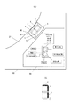
図1は、本発明の一実施形態の遊技機の説明図である。
本実施形態の遊技機10は前面枠12を備え、該前面枠12は本体枠(外枠)11にヒンジ13を介して開閉回動可能に組み付けられている。遊技盤30(図2参照)は前面枠12の表側に形成された収納部(図示省略)に収納されている。また、前面枠(内枠)12には、遊技盤30の前面を覆うカバーガラス(透明部材)14を備えたガラス枠15が開閉可能に取り付けられている。
[First Embodiment]
DESCRIPTION OF EXEMPLARY EMBODIMENTS Hereinafter, preferred embodiments of the invention will be described with reference to the drawings.
FIG. 1 is an explanatory diagram of a gaming machine according to an embodiment of the present invention.
The
また、ガラス枠15の上部には、ランプ及びモータを内蔵した照明装置(ムービングライト)16や払出異常報知用のランプ(LED)17が設けられている。また、ガラス枠15の左右にはランプ等を内蔵し装飾や演出のための発光をする枠装飾装置18や、音響(例えば、効果音)を発するスピーカ(上スピーカ)19aが設けられている。さらに、前面枠12の下部にもスピーカ(下スピーカ)19bが設けられている。
Further, an illuminating device (moving light) 16 incorporating a lamp and a motor and a lamp (LED) 17 for notifying a dispensing abnormality are provided on the upper part of the
また、前面枠12の下部には、図示しない打球発射装置に遊技球を供給する上皿21、遊技機10の裏面側に設けられている球払出装置から払い出された遊技球が流出する上皿球出口22、上皿21が一杯になった状態で払い出された遊技球を貯留する下皿23、打球発射装置の操作部24等が設けられている。さらに、上皿21の上縁部には、遊技者からの操作入力を受け付けるための操作スイッチを内蔵した演出ボタン25が設けられている。さらに、前面枠12下部右側には、前面枠12を開放したり施錠したりするための鍵26が設けられている。
In addition, at the lower part of the
この実施形態の遊技機10においては、遊技者が上記操作部24を回動操作することによって、打球発射装置が、上皿21から供給される遊技球を遊技盤30前面の遊技領域32(図2参照)に向かって発射する。また、遊技者が演出ボタン25を操作することによって、表示装置41(図2参照)における変動表示ゲーム(飾り特図変動表示ゲーム)において、遊技者の操作を介入させた演出等を行わせることができる。さらに、上皿21上方のガラス枠15の前面には、遊技者が隣設する球貸機から球貸しを受ける場合に操作する球貸ボタン27、球貸機のカードユニットからプリペイドカードを排出させるために操作する排出ボタン28、プリペイドカードの残高を表示する残高表示部(図示省略)等が設けられている。
In the
図2は、第1実施形態の遊技盤30の正面図である。
遊技盤30の表面には、ガイドレール31で囲われた略円形状の遊技領域32が形成されている。遊技領域32は、遊技盤30の四隅に各々設けられた樹脂製のサイドケース33及びガイドレール31に囲繞されて構成される。遊技領域32には、上部に鎧部40aを有し中央に表示装置41を備えた包囲枠体40が配置されている。表示装置41は、包囲枠体40に設けられた凹部に、当該包囲枠体40の前面より奥まった位置に取り付けられている。すなわち、包囲枠体40は表示装置41の表示領域(破線R)の周囲を囲い、表示装置41の表示面よりも前方へ突出し周囲の遊技領域32から遊技球が飛び込みにくくするように形成されている。
FIG. 2 is a front view of the
On the surface of the
表示装置41は、例えばLCD(液晶表示器)等の表示画面を有する装置で構成されている。表示画面の画像を表示可能な領域(表示領域R)には、複数の識別情報(特別図柄)や特図変動表示ゲームを演出するキャラクタや演出効果を高める背景画像等の遊技に関する情報が表示される。表示装置41の表示画面においては、識別情報として割り当てられた複数の特別図柄が変動表示(可変表示)されて、特図変動表示ゲームに対応した飾り特図変動表示ゲームが行われる。また、表示画面には遊技の進行に基づく演出のための画像(例えば、大当り表示画像、ファンファーレ表示画像、エンディング表示画像等)が表示される。
The
遊技領域32の包囲枠体40の左側等には、普通図柄始動ゲート(普図始動ゲート)34が設けられている。包囲枠体40の左下側には、三つの一般入賞口35が配置され、包囲枠体40の右下側には、一つの一般入賞口35が配置されている。
これら一般入賞口35、…には、各一般入賞口35に入賞した遊技球を検出するための入賞口スイッチ35a(図76参照)が配設されている。
また、包囲枠体40の下方には、特図変動表示ゲームの開始条件を与える始動入賞口36(第1始動入賞口)が設けられ、その直下には上部に逆「ハ」の字状に開いて遊技球が流入し易い状態に変換する一対の可動部材37b,37bを備えるとともに内部に第2始動入賞口を有する普通変動入賞装置(普電)37が配設されている。
A normal symbol start gate (ordinary start gate) 34 is provided on the left side of the surrounding
.. Are provided with a winning
In addition, a start winning opening 36 (first start winning opening) for providing a start condition of the special figure variation display game is provided below the surrounding
普通変動入賞装置37の一対の可動部材37b,37bは、常時は遊技球の直径程度の間隔をおいて閉じた閉状態(遊技者にとって不利な状態)を保持している。ただし、普通変動入賞装置37の上方には、始動入賞口36が設けられているので、閉じた状態では遊技球が入賞できないようになっている。
そして、普図変動表示ゲームの結果が所定の停止表示態様となった場合には、駆動装置としての普電ソレノイド37c(図76参照)によって、逆「ハ」の字状に開いて普通変動入賞装置37に遊技球が流入し易い開状態(遊技者にとって有利な状態)に変化させられるようになっている。
The pair of
When the result of the normal variation display game becomes a predetermined stop display mode, it is opened in a reverse “C” shape by a general electric solenoid 37c (see FIG. 76) as a driving device, and a normal variation prize is awarded. The
また、遊技機10は、特図変動表示ゲームの結果によって遊技球を受け入れない状態と受け入れ易い状態とに変換可能な第1特別変動入賞装置(大入賞口)38と、第2特別変動入賞装置(大入賞口)39とを備えている。
第1特別変動入賞装置38は、普通変動入賞装置37の下方に配設されている。そして、第1特別変動入賞装置38は、上端側が手前側に倒れる方向に回動して開放可能になっているアタッカー形式の開閉扉を有しており、補助遊技としての特図変動表示ゲームの結果如何によって大入賞口を閉じた状態(遊技者にとって不利な閉塞状態)から開放状態(遊技者にとって有利な状態)に変換する。
In addition, the
The first special variable winning
すなわち、第1特別変動入賞装置38は、例えば、駆動装置としての大入賞口ソレノイド38b(図76参照)により駆動される開閉扉によって開閉される大入賞口を備え、特別遊技状態中は、大入賞口を閉じた状態から開いた状態に変換することにより大入賞口内への遊技球の流入を容易にさせ、遊技者に所定の遊技価値(賞球)を付与するようになっている。
なお、第1特別変動入賞装置(大入賞口)38の内部(入賞領域)には、当該大入賞口に入った遊技球を検出する検出手段としてのカウントスイッチ38a(図76参照)が配設されている。
第1特別変動入賞装置38の下方には、入賞口などに入賞しなかった遊技球を回収するアウト口32aが設けられている。
That is, the first special variable winning
In addition, a
Below the first special variable winning
第2特別変動入賞装置39は、包囲枠体40の上部左側に配設されている。そして、第2特別変動入賞装置39は、上端側が左側に倒れる方向に回動して開放可能になっているアタッカー形式の開閉部材39cを有しており、補助遊技としての特図変動表示ゲームの結果如何によって大入賞口を閉じた状態(遊技者にとって不利な閉塞状態)から開放状態(遊技者にとって有利な状態)に変換する。
すなわち、第2特別変動入賞装置39は、例えば、駆動装置としての大入賞口ソレノイド39b(図76参照)により駆動される開閉部材39cによって開閉される大入賞口を備え、特別遊技状態中は、大入賞口を閉じた状態から開いた状態に変換することにより大入賞口内への遊技球の流入を容易にさせ、遊技者に所定の遊技価値(賞球)を付与するようになっている。
The second special
That is, the second special variable
なお、第2特別変動入賞装置(大入賞口)39の内部(入賞領域)には、当該大入賞口に入った遊技球を検出する検出手段としてのカウントスイッチ39a(図76参照)が配設されている。
また、遊技領域32の外側(例えば、遊技盤30の右下部)には、特図変動表示ゲームをなす第1特図変動表示ゲームや第2特図変動表示ゲーム及び普図始動ゲート34への入賞をトリガとする普図変動表示ゲームを一箇所で実行する一括表示装置50が設けられている。
In addition, a
In addition, on the outside of the game area 32 (for example, in the lower right part of the game board 30), the first special figure fluctuation display game, the second special figure fluctuation display game, and the general figure start
この実施例における一括表示装置50は、7セグメント型の表示器(LEDランプ)等で構成された第1特図変動表示ゲーム用の第1特図変動表示部(特図1表示器)及び第2特図変動表示ゲーム用の第2特図変動表示部(特図2表示器)と、LEDランプで構成された普図変動表示ゲーム用の変動表示部(普図表示器)と、同じくLEDランプで構成された各変動表示ゲームの始動記憶数報知用の記憶表示部などを備える。一括表示装置50の詳細については後に説明する。
The
本実施形態の遊技機10では、図示しない発射装置から遊技領域32に向けて遊技球(パチンコ球)が打ち出されることによって遊技が行われる。打ち出された遊技球は、遊技領域32内の各所に配置された障害釘や風車等の方向転換部材によって転動方向を変えながら遊技領域32を流下し、普図始動ゲート34、一般入賞口35、始動入賞口36、普通変動入賞装置37又は特別変動入賞装置38,39に入賞するか、遊技領域32の最下部に設けられたアウト口32aへ流入し遊技領域32から排出される。そして、一般入賞口35、始動入賞口36、普通変動入賞装置37又は特別変動入賞装置38,39に遊技球が入賞すると、入賞した入賞口の種類に応じた数の賞球が、払出制御装置200(図76参照)によって制御される払出ユニットから、前面枠12の上皿21又は下皿23に排出される。
In the
一方、普図始動ゲート34内には、該普図始動ゲートを通過した遊技球を検出するための非接触型のスイッチなどからなるゲートスイッチ34a(図76参照)が設けられており、遊技領域32内に打ち込まれた遊技球が普図始動ゲート34内を通過すると、ゲートスイッチ34aにより検出されて普図変動表示ゲームが行われる。
また、普図変動表示ゲームを開始できない状態、例えば、既に普図変動表示ゲームが行われ、その普図変動表示ゲームが終了していない状態や、普図変動表示ゲームが当って普通変動入賞装置37が開状態に変換されている場合に、普図始動ゲート34を遊技球が通過すると、普図始動記憶数の上限数(例えば、4個)未満ならば、普図始動記憶数が加算(+1)されて普図始動記憶が1つ記憶されることとなる。この普図始動入賞の記憶数は、一括表示装置50の普図保留表示器に表示される。
また、普図始動記憶には、普図変動表示ゲームの当りはずれを決定するための当り判定用乱数値が記憶されるようになっていて、この当り判定用乱数値が判定値と一致した場合に、当該普図変動表示ゲームが当りとなって特定の結果態様(普図特定結果)が導出されることとなる。
On the other hand, a
In addition, the normal fluctuation display game cannot be started, for example, the normal fluctuation display game has already been executed and the normal fluctuation display game has not ended, or the normal fluctuation display game has hit and the normal fluctuation winning device If 37 is converted to the open state and the game ball passes through the general figure start
In addition, in the normal chart start memory, a random number value for hit determination for determining a hit error of the normal figure fluctuation display game is stored, and when the random number value for hit determination coincides with the determination value In addition, a specific result mode (a general map specifying result) is derived by winning the normal map change display game.
普図変動表示ゲームは、一括表示装置50に設けられた変動表示部(普図表示器)で実行されるようになっている。普図表示器は、普通識別情報(普図、普通図柄)として点灯状態の場合に当りを示し、消灯状態の場合にはずれを示すLEDから構成され、このLEDを点滅表示することで普通識別情報の変動表示を行い、所定の変動表示時間の経過後、LEDを点灯又は消灯することで結果を表示するようになっている。
なお、普通識別情報として例えば数字、記号、キャラクタ図柄などを用い、これを所定時間変動表示させた後、停止表示させることにより行うように構成しても良い。この普図変動表示ゲームの停止表示が普図特定結果となれば、普図の当りとなって、普通変動入賞装置37の一対の可動部材37bが所定時間(例えば、普図低確率状態ならば0.3秒間、普図高確率状態ならば0.8秒間)開放される開状態となる。これにより、普通変動入賞装置37の内部の第2始動入賞口へ遊技球が入賞し易くなり、第2特図変動表示ゲームが実行される回数が多くなる。
The usual map variation display game is executed by a variation display unit (common diagram display) provided in the
Note that, for example, numbers, symbols, character designs, and the like may be used as the normal identification information, which is displayed by variably displaying for a predetermined time and then stopped. If the stop display of the normal map change display game results in the normal map specifying result, it becomes a hit of the normal map, and the pair of
普図始動ゲート34への通過検出時に抽出した普図乱数値が当り値であるときには、普図表示器に表示される普通図柄が当り状態で停止し、当り状態となる。このとき、普通変動入賞装置37は、内蔵されている普電ソレノイド37c(図76参照)が駆動されることにより、可動部材37bが所定の時間(例えば、普図低確率状態ならば0.3秒間、普図高確率状態ならば0.8秒間)だけ開放する状態に変換され、遊技球の入賞が許容される。
When the random number value extracted at the time of detection of the passage to the universal figure start
始動入賞口36への入賞球及び普通変動入賞装置37への入賞球は、それぞれは内部に設けられた始動口1スイッチ36aと始動口2スイッチ37aによって検出される。始動入賞口36へ入賞した遊技球は第1特図変動表示ゲームの始動入賞球として検出され、第1始動記憶として所定の上限数(例えば、4個)を限度に記憶されるとともに、普通変動入賞装置37へ入賞した遊技球は第2特図変動表示ゲームの始動入賞球として検出され、第2始動記憶として所定の上限数(例えば、4個)を限度に記憶される。
また、この始動入賞球の検出時にそれぞれ大当り乱数値や大当り図柄乱数値、並びに各変動パターン乱数値が抽出され、抽出された乱数値は、遊技制御装置100(図76参照)内の特図記憶領域(RAMの一部)に特図始動記憶として各々所定回数(例えば、最大で4回分)を限度に記憶される。そして、この特図始動記憶の記憶数は、一括表示装置50の始動入賞数報知用の記憶表示部(特図1保留表示器、特図2保留表示器)に表示されるとともに、包囲枠体40の表示装置41においても飾り特図始動記憶表示として表示される。
The winning ball to the
In addition, when the starting winning ball is detected, a big hit random number value, a big hit symbol random number value, and each variation pattern random number value are extracted. Each area (a part of the RAM) is stored as a special figure start memory for a predetermined number of times (for example, a maximum of four times). The number stored in the special figure start memory is displayed on the memory display section (the special figure 1 hold indicator, the special figure 2 hold indicator) for notifying the start winning number of the
遊技制御装置100は、始動入賞口36若しくは普通変動入賞装置37への入賞、又はそれらの始動記憶に基づいて、特図1表示器(変動表示装置)又は特図2表示器(変動表示装置)で第1又は第2特図変動表示ゲームを行う。
第1特図変動表示ゲーム及び第2特図変動表示ゲームは、複数の特別図柄(特図、識別情報)を変動表示したのち、所定の結果態様を停止表示することで行われる。また、表示装置(画像表示装置)41にて各特図変動表示ゲームに対応して複数種類の識別情報(例えば、数字、記号、キャラクタ図柄等)を変動表示させる飾り特図変動表示ゲームが実行されるようになっている。
そして、特図変動表示ゲームの結果として、特図1表示器若しくは特図2表示器の表示態様が特別結果態様(特別結果)となった場合には、大当りとなって特別遊技状態(いわゆる、大当り状態)となる。また、これに対応して表示装置41の表示態様(停止結果態様)も特別結果態様となる。従って、表示装置(画像表示装置)41が、所定の補助遊技(本実施形態の場合、変動表示ゲーム)を実行可能な補助遊技装置をなす。
The
The first special figure fluctuation display game and the second special figure fluctuation display game are performed by variably displaying a plurality of special symbols (special figures, identification information) and then stopping and displaying a predetermined result form. In addition, a decorative special figure variation display game is executed in which a plurality of types of identification information (for example, numbers, symbols, character designs, etc.) are displayed in a variable manner on the display device (image display device) 41 corresponding to each special figure variation display game. It has come to be.
As a result of the special figure variation display game, when the display form of the special figure 1 display or the special figure 2 display becomes a special result form (special result), a special game state (so-called, Big hit state). Correspondingly, the display mode (stop result mode) of the
表示装置41における飾り特図変動表示ゲームは、例えば、まず前述した数字等で構成される飾り特別図柄(識別情報)を左変動表示領域(第1特別図柄)、右変動表示領域(第2特別図柄)、中変動表示領域(第3特別図柄)のそれぞれにおいて各図柄を識別困難な速さで変動表示(高速変動)する。そして、所定時間後に変動している図柄を左変動表示領域、右変動表示領域、中変動表示領域の順に順次停止させて、左変動表示領域、右変動表示領域、中変動表示領域の各々で停止表示された識別情報により構成される停止結果態様により特図変動表示ゲームの結果を表示することで行われる。また、表示装置41では、特図始動記憶数に対応する飾り特別図柄による変動表示ゲームを行うとともに、興趣向上のためにキャラクタの出現など多様な演出表示が行われる。
For example, in the decorative special figure variation display game in the
なお、特図1表示器、特図2表示器は、別々の表示器でも良いし同一の表示器でも良いが、各々独立して、また、同時には実行しないように各特図変動表示ゲームが表示される。また、表示装置41も、第1特図変動表示ゲームと第2特図変動表示ゲームで別々の表示装置や別々の表示領域を使用するとしても良いし、同一の表示装置や表示領域を使用するとしても良いが、各々独立して、また、同時には実行しないように飾り特図変動表示ゲームが表示される。また、遊技機10に特図1表示器、特図2表示器を備えずに、表示装置41のみで特図変動表示ゲームを実行するようにしても良い。
Note that the special figure 1 display and the special figure 2 display may be separate displays or the same display, but each special figure variation display game is not to be executed independently or simultaneously. Is displayed. In addition, the
また、第2特図変動表示ゲームは、第1特図変動表示ゲームよりも優先して実行されるようになっている。すなわち、第1特図変動表示ゲームと第2特図変動表示ゲームの始動記憶がある場合であって、特図変動表示ゲームの実行が可能となった場合は、第2特図変動表示ゲームが実行されるようになっている。
また、第1特図変動表示ゲーム(第2特図変動表示ゲーム)が開始可能な状態で、且つ、始動記憶数が0の状態で、始動入賞口36(若しくは、普通変動入賞装置37)に遊技球が入賞すると、始動権利の発生に伴って始動記憶が記憶されて、始動記憶数が1加算されるととともに、直ちに始動記憶に基づいて、第1特図変動表示ゲーム(第2特図変動表示ゲーム)が開始され、この際に始動記憶数が1減算される。
Further, the second special figure variation display game is executed with priority over the first special figure variation display game. That is, when there is a start memory of the first special figure fluctuation display game and the second special figure fluctuation display game, and the special figure fluctuation display game can be executed, the second special figure fluctuation display game is It is supposed to be executed.
In addition, in the state where the first special figure fluctuation display game (second special figure fluctuation display game) can be started and the number of start memories is zero, the start winning opening 36 (or the normal fluctuation prize winning device 37) is entered. When the game ball wins, the start memory is stored as the start right is generated, the start memory number is incremented by 1, and the first special figure variation display game (second special figure) is immediately added based on the start memory. (Variable display game) is started, and at this time, the start memory number is decremented by one.
一方、第1特図変動表示ゲーム(第2特図変動表示ゲーム)が直ちに開始できない状態、例えば、既に第1若しくは第2特図変動表示ゲームが行われ、その特図変動表示ゲームが終了していない状態や、特別遊技状態となっている場合に、始動入賞口36(若しくは、普通変動入賞装置37)に遊技球が入賞すると、始動記憶数が上限数未満ならば、始動記憶数が1加算されて始動記憶が1つ記憶されることになる。そして、始動記憶数が1以上となった状態で、第1特図変動表示ゲーム(第2特図変動表示ゲーム)が開始可能な状態(前回の特図変動表示ゲームの終了若しくは特別遊技状態の終了)となると、始動記憶数が1減算されるとともに、記憶された始動記憶に基づいて第1特図変動表示ゲーム(第2特図変動表示ゲーム)が開始される。
以下の説明において、第1特図変動表示ゲームと第2特図変動表示ゲームを区別しない場合は、単に特図変動表示ゲームと称する。
On the other hand, a state in which the first special figure fluctuation display game (second special figure fluctuation display game) cannot be started immediately, for example, the first or second special figure fluctuation display game has already been performed, and the special figure fluctuation display game has ended. If the game ball is won in the start winning opening 36 (or the normal variable prize winning device 37) in a state that is not in the special game state or in the special game state, the start memory number is 1 if the start memory number is less than the upper limit number. By adding, one start memory is stored. Then, in a state where the starting memory number becomes 1 or more, a state in which the first special figure fluctuation display game (second special figure fluctuation display game) can be started (the end of the previous special figure fluctuation display game or the special game state) (End), the start memory number is decremented by 1, and the first special figure fluctuation display game (second special figure fluctuation display game) is started based on the stored start memory.
In the following description, when the first special figure fluctuation display game and the second special figure fluctuation display game are not distinguished, they are simply referred to as a special figure fluctuation display game.
なお、特に限定されるわけではないが、上記始動入賞口36内の始動口1スイッチ36a、普通変動入賞装置37内の始動口2スイッチ37a、ゲートスイッチ34a、一般入賞口スイッチ35a、カウントスイッチ38aには、ワープ流路604内の流路スイッチ(後述)、磁気検出用のコイルを備え該コイルに金属が近接すると磁界が変化する現象を利用して遊技球を検出する非接触型の磁気近接センサ(以下、近接スイッチと称する)が使用されている。また、遊技機10のガラス枠15等に設けられた前枠開放検出スイッチ63や前面枠(遊技枠)12等に設けられた遊技枠開放検出スイッチ64には、機械的な接点を有するマイクロスイッチを用いることができる。
Although not particularly limited, the starting
次に、包囲枠体(所謂センターケース)40の詳細な構造について説明する。
図3は、包囲枠体40を前面側から見た分解斜視図である。
包囲枠体40は、図3に示すように、表示装置41等を備える裏面構成部材(制御ユニット)700と、裏面構成部材700の前面に装着される前面構成部材(前側飾りユニット)600と、からなる。そして、前面構成部材600は、遊技盤30の前面側から開口部30Aに挿入され、裏面構成部材700は遊技盤30の後方から開口部30Aに挿入され、開口部30A内にて前面構成部材600の後面と裏面構成部材700の前面の一部が接合もしくは係合される。
Next, the detailed structure of the surrounding frame (so-called center case) 40 will be described.
FIG. 3 is an exploded perspective view of the
As shown in FIG. 3, the surrounding
つまり、遊技機10は、遊技領域32が形成される遊技盤30(具体的には、木製ベニヤ板やアクリル板等で構成される遊技盤30本体)に配設される遊技用部材(包囲枠体40や入賞口装置(第1特別変動入賞装置38等))を備え、遊技盤30の後面側には、遊技を制御するための制御装置(遊技制御装置100)が配設されている。そして、遊技用部材(包囲枠体40や入賞口装置(第1特別変動入賞装置38等))は、遊技盤30に形成される開口を塞ぐように当該遊技盤30に取り付けられている。
That is, the
図4には、包囲枠体の前面構成部材600の詳細な構造が示されている。なお、図4は、前面構成部材600を前面側から見た斜視図である。
図4に示すように、包囲枠体の前面構成部材600は、開口部600Aが形成された枠状をなしており、当該前面構成部材600の下部に、遊技球を転動させてから包囲枠体40の下方に流下させるステージ601を備えている。
ステージ601には、当該ステージ601上の遊技球が転動する領域と前面構成部材600の開口部600Aとを仕切る仕切り部材602や、当該ステージ601上を転動する遊技球を包囲枠体40の下方に流下させることが可能な誘導流路603が設けられている。
仕切り部材602は、主に、少なくとも遊技球が転動可能な間隔をあけてステージ601の上面と対向するように配設された庇部602aと、庇部602aの下面後端部からステージ601の上面後端部に亘って配設された奥壁部602bと、を備えて構成される。
FIG. 4 shows the detailed structure of the front
As shown in FIG. 4, the front
The
The
誘導流路603は、仕切り部材602の奥壁部602bの前面略中央部からステージ601の前面略中央部に亘って設けられ、包囲枠体40の内部(ステージ601と庇部602aとの間)に向けて開口する誘導導入口603aと、ステージ601の前面のうち始動入賞口36の上方となる部分(具体的には、ステージ601の前面略中央部)に設けられ包囲枠体40の外部に向けて開口する誘導導出口603bと、を有し、当該誘導導入口603aと当該誘導導出口603bとを連通する流路である。すなわち、ステージ601は、誘導流路603によって、包囲枠体40の内部に開設された誘導導入口603aに流入した遊技球を包囲枠体40の前面に開設された誘導導出口603bを介して包囲枠体40の外部の始動入賞口36の直上方へ誘導できるよう構成されている。
The
また、前面構成部材600は、当該前面構成部材600の左部に、遊技領域32を流下する遊技球を包囲枠体40の内部へ誘導することが可能なワープ流路604を備えている。
ワープ流路604は、前面構成部材600の左部上側に設けられ包囲枠体40の外部に向けて開口するワープ入口604aと、前面構成部材600の左部下側に設けられ包囲枠体40の内部(具体的には、ステージ601と庇部602aとの間)に向けて開口するワープ出口604bと、を有し、当該ワープ入口604aと当該ワープ出口604bとを連通する流路である。すなわち、前面構成部材600は、ワープ流路604によって、包囲枠体40の左側面に開設されたワープ入口604aに流入した遊技球を包囲枠体40の内部に開設されたワープ出口604bを介して包囲枠体40の内部のステージ601上(球転動部)へ誘導できるよう構成されている。
The
The
このように、遊技機10は、遊技盤30に形成される遊技領域32に臨む前面開口凹室状の包囲枠体40と、遊技領域32のうち包囲枠体40の下方に位置する部分に配設される入賞口(始動入賞口36)と、遊技球が転動可能なステージ601と、遊技領域32を流下する遊技球をステージ601へ誘導することが可能なワープ流路604と、ステージ601を転動する遊技球を包囲枠体40の下方に流下させて入賞口(始動入賞口36)の直上方へ誘導することが可能な誘導流路603と、を備えている。
As described above, the
また、図4に示すように、前面構成部材600の上部左側には、ベニヤ板等で構成される遊技盤30本体に包囲枠体40を取り付けるためのフランジ部600bや、遊技球が表示装置41の左側方又は右側方を流下するように案内するための鎧部600c等が設けられている。
さらに、前面構成部材600は、当該前面構成部材600の上部左側に、第2特別変動入賞装置39を備えている。また、前面構成部材600は、当該前面構成部材600の右部に、発光演出装置610を備えている。
Further, as shown in FIG. 4, on the upper left side of the front
Further, the
図5には、上記包囲枠体40を構成する裏面構成部材700の分解斜視図が示されている。なお、図5は、裏面構成部材700を前面側から見た分解斜視図である。
図5に示すように、裏面構成部材700は、主に、開口部710aが形成された枠状をなす制御ベース部材710と、開口部721aが形成された枠状をなし制御ベース部材710の開口部710a内に装着される盤演出装置としての枠体演出装置430と、制御ベース部材710の後面に装着される表示ユニット730と、を備えて構成される。
FIG. 5 shows an exploded perspective view of the back
As shown in FIG. 5, the
表示ユニット730は、表示装置41と、表示装置41の後面に取り付けられた表示制御装置42と、からなる。
表示装置41の表示領域は、制御ベース部材710の開口部710aと、枠体演出装置430の開口部(具体的には、枠体演出装置430が備える演出ベース部材721の開口部721a)と、前面構成部材600の開口部600A(図4参照)と、を介して遊技機10の前方から視認可能となっている。
The
The display area of the
図6には、枠体演出装置430の詳細な構造が示されている。なお、図6は、枠体演出装置430を前面側から見た分解斜視図である。
図6に示すように、枠体演出装置430は、主に、開口部721aが形成された枠状をなす演出ベース部材721と、演出ベース部材721の前面左部に装着される球通路部材723と、演出ベース部材721の上部に装着され当該演出ベース部材721の開口部721aから露出する表示装置41の表示部(表示領域R)を仕切ることが可能な表示部仕切り演出ユニット440と、前面下部に装着される下部演出ユニット800と、演出ベース部材721の前面右部に装着される側部演出ユニット900と、を備えて構成される。
FIG. 6 shows a detailed structure of the frame
As shown in FIG. 6, the frame
球通路部材723は、第2特別変動入賞装置39の入賞球排出口39e(図5参照)に連通する(或いは、入賞球排出口39eと遊技球の直径未満の間隔をあけて対向する)中部入賞球導入口723aと、下部演出ユニット800の左部に向けて開口する中部入賞球導出口723bと、を有し、当該中部入賞球導入口723aと当該中部入賞球導出口723bとを連通する流路である。
また、下部演出ユニット800の左部には、下部入賞球流路801が設けられている。下部入賞球流路801は、中部入賞球導出口723bに連通する(或いは、中部入賞球導出口723bと遊技球の直径未満の間隔をあけて対向する)下部入賞球導入口801aと、包囲枠体40の外部に向けて開口する下部入賞球導出口801bと、を有し、当該下部入賞球導入口801aと当該下部入賞球導出口801bとを連通する流路である。
The
Further, a lower winning
すなわち、裏面構成部材700は、球通路部材723及び下部入賞球流路801によって、第2特別変動入賞装置39の入賞球排出口39eを介して前面構成部材600の外部へと排出された遊技球を、包囲枠体40の外部(遊技盤30の裏面(後面)側下部)へと誘導して排出できるよう構成されている。
表示部仕切り演出ユニット440は、演出ベース部材721の開口部721a内を左右方向にスライド移動可能な棒状の可動仕切り部材48A,48Bと、演出ベース部材721の上部に設けられ可動仕切り部材48A,48Bをスライド移動させるための駆動力を発生することが可能な仕切り部材駆動モータ441A,441Bと、を有している。表示部仕切り演出ユニット440は、可動仕切り部材48A,48Bが左右方向にスライド移動することによって、表示装置41の表示領域Rを左右に仕切る状態と、表示装置41の表示領域Rを仕切らない状態と、に変換可能となっている。
演出ベース部材721の右側部には側部演出ユニット900が前面側から装着される。側部演出ユニット900は、可動アーム941とその先端に固定された可動装飾部材942とこれを駆動するモータ741を含む駆動部740などからなり、可動アーム941は演出ベース部材721の右側部に設けられた支持軸943を中心に円弧状に回動される。
That is, the back
The display section
A
次に、表示部仕切り演出ユニット440の詳細について説明する。
図7には、下部演出ユニット800及び側部演出ユニット900を取り外した状態の枠体演出装置430の斜視図が示されている。
図7に示すように、枠体演出装置430は、取付ベース部材434の左側部の上記隔壁434aより外側に上記球通路部材723が垂直方向に配設され、右側部に前記側部演出ユニット900を駆動する側部演出ユニット駆動部740を構成する演出ユニット用モータ741が配設されている。
また、図7に示すように、前述した第1可動仕切り部材48Aおよび第2可動仕切り部材48Bは、前後にずれて配置されており、第1可動仕切り部材48Aは第2可動仕切り部材48Bの前方を左右方向に、また第2可動仕切り部材48Bは第1可動仕切り部材48Aの後方を左右方向に移動可能、つまりすれ違い可能に構成されている。そして、第1可動仕切り部材48Aと第2可動仕切り部材48Bとの間には、スペーサとして機能する中部材435が設けられている。
Next, details of the display unit
FIG. 7 shows a perspective view of
As shown in FIG. 7, in the frame
Further, as shown in FIG. 7, the first
そして、上記表示部仕切り演出ユニット440の上面には、上記第1可動仕切り部材48Aを移動させるための第1モータ441Aと第2可動仕切り部材48Bを移動させるための第2モータ441Bとが設けられている。後に詳しく説明するように、第1可動仕切り部材48Aと第2可動仕切り部材48Bは水平方向に配置されたスライドシャフトによって移動可能に垂下され、第1モータ441Aと第2モータ441Bの駆動力は、それぞれベルトによって第1可動仕切り部材48Aと第2可動仕切り部材48Bに伝達されるように構成されている。
図8には、図7に示す枠体演出装置430から球通路部材723と下カバー部材433を取り外した状態が示されている。図8から分かるように、第1可動仕切り部材48Aの下端は取付ベース部材434の下部の中部材435の前面に沿って、また第2可動仕切り部材48Bの下端は中部材435の裏面に沿って移動するように、配置されている。
A
FIG. 8 shows a state where the
また、図8に示されているように、取付ベース部材434の前面左側の球通路部材723(図7参照)の背部となる位置には、球通路部材723を止着するためのボス部434bが設けられている。また、取付ベース部材434の下部の中部材435の前面には、下カバー部材433を適当な間隔をおいて平行に止着するためのボス部435bが設けられ、中部材435との下カバー部材433との隙間内を第1可動仕切り部材48Aの下端部が移動可能にされている。
さらに、取付ベース部材434の下面には、第1可動仕切り部材48Aおよび第2可動仕切り部材48Bから引き出され第1可動仕切り部材48Aおよび第2可動仕切り部材48Bに設けられているLEDランプに給電するための配線が接続される役物中継基板436が取り付けられている。
Further, as shown in FIG. 8, a
Further, the lower surface of the mounting
また、中部材435の前面右側端部には、第1可動仕切り部材48Aが最も右側まで移動されていることを検出するための第1仕切り部材右位置検出部437Aが設けられている。一方、中部材435の前面左側端部には、第1可動仕切り部材48Aが最も左側まで移動されていることを検出するための第1仕切り部材左位置検出部438Aが設けられている。
図9には、第1仕切り部材右位置検出部437Aの詳しい構造が示されている。図9に示されているように、第1可動仕切り部材48Aの下端には、左右方向に延びた下水平支持部481が固定され、該下水平支持部481の右端には、第1仕切り部材右位置検出片481aが設けられている。また、下水平支持部481の前面左側端部には、第1仕切り部材左位置検出片481bが設けられている。一方、中部材435の前面右側端部には、上記、第1仕切り部材右位置検出片481aを前後から挟むようなコの字状の透過型光電式センサ438Aが設けられている。
Further, a first partition member right
FIG. 9 shows the detailed structure of the first partition member right
図10には、図8に示す枠体演出装置430から中部材435と第1可動仕切り部材48Aを取り外した状態が示されている。図10から分かるように、取付ベース部材434の下部の前面には、中部材435を止着するためのボス部434cが設けられている。また、取付ベース部材434の下部前面右側部には、第2可動仕切り部材48Bが最も右側まで移動されていることを検出するための第2仕切り部材右位置検出部438Bが設けられている。一方、取付ベース部材434の下部前面左側部には、第2可動仕切り部材48Bが最も右側まで移動されていることを検出するための第2仕切り部材左位置検出部437Bが設けられている。
FIG. 10 shows a state in which the
図11には、第2仕切り部材右位置検出部437Bの詳しい構造が示されている。
図11に示されているように、第2可動仕切り部材48Bの下端には、左右方向に延びた下水平支持部482が固定され、該下水平支持部482の左端には、第2仕切り部材左位置検出片482aが設けられている。また、下水平支持部482の前面右側端部には、第2仕切り部材右位置検出片482bが設けられている。一方、取付ベース部材434の下部前面左側部には、上記第2仕切り部材左位置検出片482aを前後から挟むようなコの字状の透過型光電式センサ439Bが設けられている。
上記各検出部のセンサの検出信号は、遊技機裏面の制御装置(演出制御基板)へ入力される。
FIG. 11 shows a detailed structure of the second partition member right
As shown in FIG. 11, a lower
The detection signals of the sensors of the detection units are input to a control device (production control board) on the back of the gaming machine.
図12には、図7に示す枠体演出装置430を前方から見た正面図が示されている。
図12に示されているように、第1可動仕切り部材48Aはユニット上部に水平方向に配置された第1スライドシャフト442Aによって左右方向移動可能に垂下されている。また、前述したように、第1可動仕切り部材48Aおよび第2可動仕切り部材48Bは、前後にずれて配置されており、上記第1スライドシャフト442Aと同一高さ位置であってその後方には、第2可動仕切り部材48Bを左右方向移動可能に垂下する第2スライドシャフト442B(図12では見えない)が設けられている。
FIG. 12 shows a front view of the
As shown in FIG. 12, the first
そして、上記第1可動仕切り部材48Aと第2可動仕切り部材48Bの上端部には、上記第1スライドシャフト442Aと第2スライドシャフト442Bにそれぞれ挿通可能な貫通穴を有する第1スライダー483Aと第2スライダー483Bがそれぞれ設けられている。
また、第1スライドシャフト442Aと第2スライドシャフト442Bの上方には、第1可動仕切り部材48Aと第2可動仕切り部材48Bを左右方向に移動させるための第1ベルト443Aと第2ベルト443Bがそれぞれ水平方向に配置され、表示部仕切り演出ユニット440の上プレート444には、上記第1ベルト443Aを移動させるための第1モータ441Aと、第2ベルト443Bを移動させるための第2モータ441Bとが設けられている。なお、第1ベルト443Aと第2ベルト443Bは、互いに干渉するのを防止するために、上下にずらした状態に配置されている。
A
Also, above the
図13には、図10に示す枠体演出装置430から表示部仕切り演出ユニット440の上プレート444を取り外した状態が示されている。図13から分かるように、取付ベース部材434の上部右側部に固定された右シャフト支持部材445Aと、取付ベース部材434の上部左側部に固定された左シャフト支持部材445Bとの間に、上記第1スライドシャフト442Aと第2スライドシャフト442Bとが水平状態で互いに平行に支持されている。
また、第1スライダー483Aの上面には上記第1ベルト443Aが捲回される第1プーリ446Aが、第2スライダー483Bの上面には上記第2ベルト443Bが捲回される第2プーリ446Bが、それぞれ回転可能に取り付けられている。一方、左シャフト支持部材445Bの上方であって取付ベース部材434の上部左側部には上記第1ベルト443Aが捲回される第1緩衝プーリ447Aが、右シャフト支持部材445Aの上方であって取付ベース部材434の上部右側部には上記第2ベルト443Bが捲回される第2緩衝プーリ447Bが、それぞれ回転可能に取り付けられている。
FIG. 13 shows a state where the
In addition, a
第1プーリ446Aには、一対のギヤ448Aを介して前記第1モータ441Aの回転力が伝達され、該プーリが第1ベルト443Aを駆動して第1スライダー483Aを移動させる。また、第2プーリ446Bには、一対のギヤ448Bを介して前記第2モータ441Bの回転力が伝達され、該プーリが第2ベルト443Bを駆動して第2スライダー483Bを移動させる。
図14には、図13に示す表示部仕切り演出ユニット440を上方から見た状態が示されている。図14から分かるように、第1緩衝プーリ447Aは、圧縮バネを内蔵したプーリ支持アーム449Aによって回転可能に支持されており、図示しないが、このプーリ支持アーム449Aの反対側(図14では右端)の固定部449aは取付ベース部材434に固着されている。また、同様に、第2緩衝プーリ447Bは、圧縮バネを内蔵したプーリ支持アーム449Bによって回転可能に支持されており、図示しないが、このプーリ支持アーム449Bの反対側(図14では左端)の固定部449bは取付ベース部材434に固着されている。
The rotational force of the
FIG. 14 shows a state in which the display section
図15には、表示部仕切り演出ユニット440から第1可動仕切り部材48Aおよび第1スライドシャフト442Aと、第1モータ441Aおよび第1ベルト443A、第1プーリ446Aを取り外した第2可動仕切り部材48Bの駆動機構の斜視図が、また図16には図15の第2可動仕切り部材48Bの駆動機構を前方から見た正面図が示されている。さらに、図17には、図16に示されている第2可動仕切り部材48Bの駆動機構を上方から見た平面図が示されている。
FIG. 15 shows the second
図18には、第2可動仕切り部材48Bを拡大した斜視図が示されている。
図18から分かるように、第2可動仕切り部材48Bは、全体として中央が内側へ膨んだ形状をなし、上端部に、第2スライドシャフト442Bに挿通可能なシャフト挿通穴483bを有する第2スライダー483Bが設けられている。そして、この第2スライダー483Bの内側端部(図18では右端)には、上方へ向かって突出し前記第2ベルト443Bを前後から挟持するためのベルト挟持部483Cと蓋部材484が設けられている。また、第2可動仕切り部材48Bの下端には前記下水平支持部482が固定され、該下水平支持部482の左端には、第2仕切り部材左位置検出片482aが設けられ、下水平支持部482の前面右側端部には、第2仕切り部材右位置検出片482bが設けられている。
FIG. 18 is an enlarged perspective view of the second
As can be seen from FIG. 18, the second
図19には、図18の第2可動仕切り部材48Bを分解した状態の斜視図が示されている。
図19に示されているように、第2可動仕切り部材48Bは、該第2可動仕切り部材48Bの第2スライダー483B裏面に接合される蓋部材484と、前面に複数個の発光ダイオードLEDが実装され本体部の裏面側に装着されるLED基板486と、位置検出片482aおよび482bを備え下端部の下水平支持部482に係合される位置検出部材487とを備える。なお、第1可動仕切り部材48Aは第2可動仕切り部材48Bと左右対称的な形状を有する点が異なり、構造は同一であるので、第1可動仕切り部材48Aについては構造の説明を省略する。
FIG. 19 shows a perspective view of the second
As shown in FIG. 19, the second
図20には、第2可動仕切り部材48Bの上端部の第2スライダー483Bを分解した状態の斜視図が示されている。
第2スライダー483Bは裏面が開口し内部が空洞となるように形成されており、図20に示されているように、第2スライダー483Bとその裏面に接合される蓋部材484との間に形成される空間内に、上記第2スライドシャフト442Bに上下から挟むように接触する2組のローラー841a,841b;841c,841dと、これらのローラーをそれぞれ回転自在に支持する2組のローラー軸842a,842b;842c,842dと、第2スライドシャフト442Bに前後から挟むように接触するガイド軸843a,843b;843c,843dとが収納されるようになっている。
FIG. 20 is a perspective view showing a state in which the
The
そして、蓋部材484Aの内面(図20では前面)には、上記ローラー軸842a,842b;842c,842dの端部が係合されることでこれらを支承する係合凹部484a,484b;484c,484dが形成されている。また、蓋部材484の内面(図20では前面)には、上記第2スライドシャフト442Bの上下に位置して対向する2組のシャフト接合片845a,845b;845c,845dが、前方へ突出するように形成されている。
図21には、図20の第2スライダー483Bを組み立てて第2スライドシャフト442Bを挿通した状態における上記ローラー841a,841b;841c,841dおよびローラー軸842a,842b;842c,842d、シャフト接合片845a,845b;845c,845dと、第2スライドシャフト442Bとの関係が示されている。
The end portions of the
FIG. 21 shows the
図21に示されているように、2組のローラー841a,841b;841c,841dは、2組のローラー軸842a,842b;842c,842dに係合され、第2スライドシャフト442Bを上下から挟むように接触している。
また、2組のシャフト接合片845a,845b;845c,845dに第2スライドシャフト442Bが挿通されるとともに、シャフト接合片845a,845b;845c,845dの先端面に接触するようにガイド軸843a,843cが垂直姿勢で配置され、シャフト接合片845a,845b;845c,845dの内側面に接触するようにガイド軸843b,843dが垂直姿勢で配置され、第2スライドシャフト442Bに前後から挟むような構造になっている。
上記のような構造を設けることで、第2可動仕切り部材48B上端の第2スライダー483Bが第2スライドシャフト442Bに沿って安定して移動することが可能となっている。さらに、上記ガイド軸843a,843c;843b,843dおよび第2スライドシャフト442Bはステンレス等の金属で、また上記ローラー841a,841b;841c,841dはポリアセタール等の合成樹脂で、また上記ローラー軸842a,842b;842c,842dはステンレス等の金属でそれぞれ形成されているため、スムーズなスライドや回転が可能となり、周りの樹脂材の摩耗を防ぐことができるという利点がある。
As shown in FIG. 21, the two sets of
The
By providing the structure as described above, the
図22には、第2スライダー483Bから蓋部材484を外した状態の裏面拡大図が示されている。
第2スライダー483Bは内部が空洞となるように形成されており、図22に示されているように、第2スライダー483Bの裏面側には上記2組のローラー軸842a,842b;842c,842dの前端部がそれぞれ係合される係合凹部486a,486b;486c,486dが形成されている。また、第2スライダー483Bの裏面側左右両端部には、上記ガイド軸843a,843cが垂直姿勢で収納されるガイド軸収納部487a,487bが、またその近傍には、ガイド軸843b,843dの上下両端部に前面側から接触して蓋部材484へ向かって押圧するガイド軸押圧凸部488a,488b;488c,488dが形成されている。
さらに、第2スライダー483Bの上面より突出するように設けられた上記ベルト挟持部483cの上端には、ベルト443Bの複数の歯部と噛合可能な凹凸を有するベルト噛合部483dが設けられている。第1スライダー483Aも、第2スライダー483Bと左右対称的な形状を有する点が異なり、構造は同一であるので、第1スライダー483Aについては構造の説明を省略する。
FIG. 22 shows an enlarged back view of the
The
Furthermore, a
図23には、第2可動仕切り部材48Bの下端部に設けられる下水平支持部482の拡大斜視図が示されている。
図23に示されているように、下水平支持部482の左端には第2仕切り部材左位置検出片482aが、また、下水平支持部482の前面右側端部には第2仕切り部材右位置検出片482bが設けられている。また、下水平支持部482に設けられた位置検出部材487は断面がほぼL状に形成され、上方のLED基板486から引き出されたフラット配線ケーブル489Bが垂直片部487cに沿って配設され、水平片部487d上で折り畳まれて方向を変え、水平片部487dに沿って第2仕切り部材右位置検出片482bの方向へ延設され、途中に設けられたスリット状の破線引き出し部487eから下方へ引き出されるように構成されている。なお、位置検出部材487には複数のビス穴487fが設けられており、該ビス穴487fを介して図示しないビスによって位置検出部材487が第2可動仕切り部材48Bの下端部に固定されるようになっている。第1可動仕切り部材48Aの下端部の下水平支持部481(図9参照)も同様の構造を有している。
FIG. 23 is an enlarged perspective view of the lower
23, the second partition member left
図24には、第2可動仕切り部材48Bから引き出されたフラット配線ケーブル489Bおよび第1可動仕切り部材48Aから引き出されたフラット配線ケーブル489Aと、取付ベース部材434(図8参照)の下部に固定された役物中継基板436との関係が示されている。
第1可動仕切り部材48Aと第2可動仕切り部材48Bは、それぞれ表示装置41の右側から左側までもしくはその逆に移動可能であるため、図24に示されているように、フラット配線ケーブル489Aと489Bは、第1可動仕切り部材48Aと第2可動仕切り部材48Bが各々初期位置にある場合には弛んだ状態になるように長さが設定されている。また、フラット配線ケーブル489Aと489Bの先端は、それぞれ役物中継基板436の下面側において、基板側の端子と電気的に接続されるように構成されている。
24, the
Since the first
図25には、第1可動仕切り部材48Aが左側へ移動し第2可動仕切り部材48Bが右側へ移動した場合における、フラット配線ケーブル489Aおよび489Bと役物中継基板436との関係が示されている。この場合、図25(A)に示すように、フラット配線ケーブル489Aと489Bとは正面から見た場合に重なることになる。ただし、図25(B)に示すように、フラット配線ケーブル489Aと489Bは、中部材435を挟んで前後にずれているので、第1可動仕切り部材48Aと第2可動仕切り部材48Bが逆方向へ移動したとしてもフラット配線ケーブル489Aと489Bとが干渉してしまうことはない。
しかも、フラット配線ケーブル489Aと489Bの先端が役物中継基板436の下面側にて基板側の端子に接続されているため、ケーブルが交差するように移動することでケーブルが変形したとしても、ケーブルの接続箇所に大きな力が働くのを回避することができ、可動仕切り部材が移動を繰り返すことでケーブルの接続箇所が切断される故障が発生するのを抑制することができる。
FIG. 25 shows the relationship between the
Moreover, since the tips of the
次に、上記のような構成を有する枠体演出装置430および表示装置41を使用した演出および表示の例について、図26〜図38を用いて説明する。先ず、表示装置41を使用した表示の例について説明する。
第1の表示例は、図26(A)に示すように、表示装置41の表示領域の中央部に数字やアルファベットなどの識別図柄を複数個用いて実行する飾り特図変動表示ゲームを表示する領域を確保するとともに、表示領域の上部には特図1始動記憶数(保留数)を表示する特図1始動記憶数表示領域SM11及び特図2始動記憶数(保留数)を表示する特図2始動記憶数表示領域SM12と、遊技盤30の右下に設けられている一括表示装置50(図2参照)の特図1表示器51と同様な表示形態で特図1変動表示ゲームの結果を表示する領域CG11及び特図2表示器52と同様な表示形態で第2特図変動表示ゲームの結果を表示する領域CG12とを設けている。また、表示領域の上部であって上記特図ゲーム表示領域CG11及びCG12から少し離れた位置に、それらと同様な表示形態で特図1及び特図2の特図変動表示ゲームの結果を表示する特図ゲーム表示領域CG21及びCG22を設けている。
Next, examples of effects and displays using the
In the first display example, as shown in FIG. 26 (A), a decorative special figure variation display game to be executed using a plurality of identification symbols such as numerals and alphabets is displayed at the center of the display area of the
上記のように、特図変動表示ゲームの結果を表示する領域を表示装置41の表示領域の上部に設けることで、遊技者は表示領域の中央に表示される演出を楽しみつつ遊技盤30の右下に設けられている一括表示装置50へ視点を移さずに本来の特図変動表示ゲームの結果を確認することができる。また、上記のように特図変動表示ゲームの結果を表示する領域を2組設けることで、例えば図26(B)のように、第1可動部材48Aが移動して特図ゲーム表示領域CG21及びCG22を隠してしまったとしても、他方の特図ゲーム表示領域CG11及びCG12は前方から視認可能である。同様に、図27(A)のように、第1可動部材48Aが移動して特図ゲーム表示領域CG11及びCG12を隠してしまったとしても、他方の特図ゲーム表示領域CG21及びCG22は前方から視認可能である。そのため、本来の特図変動表示ゲームの結果を確実に視認することができる。
As described above, by providing an area for displaying the result of the special figure variation display game at the upper part of the display area of the
さらに、第1の表示例は、図26(A)に示すように、表示装置41の表示領域の下部に、発生した始動記憶の数に応じて表示するマークの数を変化させるようにして特図1始動記憶数(保留数)を表示する特図1始動記憶数表示領域SM21および特図2始動記憶数(保留数)を表示する特図2始動記憶数表示領域SM22を設けてある。そのため、例えば図27(B)のように、第1可動部材48Aが移動して表示領域上部の特図始動記憶数表示領域SM11およびSM12を隠してしまったとしても、表示領域下部の始動記憶数表示領域SM21は前方から視認可能であるため、始動記憶数をいつでも確認することができる。同様にして、図27(A)のように、第1可動部材48Aが移動して表示領域下部の特図始動記憶数表示領域SM22を隠してしまったとしても、表示領域上部の始動記憶数表示領域SM11およびSM12は前方から視認可能である。
Furthermore, as shown in FIG. 26 (A), the first display example is characterized by changing the number of marks to be displayed at the bottom of the display area of the
次に、枠体演出装置430を使用した演出例について説明する。
第1の演出例は、変動表示ゲーム実行中に、例えば図27(B)のように、第1可動部材48Aを左方へ移動させて、表示装置41の表示領域を中央表示領域A0と右演出表示領域A1とに分割し、中央表示領域A1では飾り特図変動表示ゲームを表示する一方、右演出表示領域A1には図27(A)のようにキャラクタC1を登場させて、図27(B)のように、キャラクタC1が第1可動部材48Aを移動させているかのような演出を行うというものである。
Next, an example of effect using the
In the first effect example, during the execution of the variable display game, for example, as shown in FIG. 27B, the first
第2の演出例は、変動表示ゲーム実行中に、例えば図28(A)のように、第1可動部材48Aを左方へ、また第2可動部材48Bを右方へ移動させて、表示装置41の表示領域を中央表示領域A0と右演出表示領域A1およびA2とに分割し、中央表示領域A0では飾り特図変動表示ゲームを表示する一方、右演出表示領域A1にはキャラクタC1を、また左演出表示領域A2にはキャラクタC2を登場させて、図28(B)のように、キャラクタC1が第1可動部材48Aを左方へ移動させているような動きをさせるとともに、キャラクタC2が第2可動部材48Bを右方へ移動させているような動きをさせて中央表示領域A0が消滅するような演出を行う。そして、その後、図29(A)のように、第1可動部材48Aと第2可動部材48Bがさらに移動してすれ違い、特図変動表示ゲームを表示する中央表示領域A0が再度出現して、図29(B)のように、変動中の図柄が停止するような演出を行うというものである。
In the second effect example, during execution of the variable display game, for example, as shown in FIG. 28A, the first
上述のように、表示装置41の表示領域の表示内容と枠体演出装置430の可動部材の移動が関連するような演出を行うことにより、遊技の興趣を高めることができる。
また、上記実施形態では、第1可動部材48Aと第2可動部材48Bとして、各々中央が内側へ膨出した形状をなすものを使用しているため、第1可動部材48Aと第2可動部材48Bが動作を開始する前においては、図30(A)のように、表示装置41の表示領域の両側部が狭くなっていたものが、第1可動部材48Aと第2可動部材48Bが動作してそれぞれ反対側まで移動した場合には、図30(B)のように、表示装置41の表示領域の両側部が広くなって拡大表示領域E1,E2を出現させることができる。これによって、第1可動部材48Aと第2可動部材48Bの作動後においては、大きな表示領域で迫力のある演出表示を実行することができるようになる。
As described above, the entertainment of the game can be enhanced by performing an effect in which the display contents of the display area of the
Further, in the above embodiment, since the first
次に、表示装置41の表示領域上部に設けられる特図1始動記憶数表示領域SM11および特図2始動記憶数表示領域SM12と、特図1変動表示ゲーム表示領域CG11および第2特図変動表示ゲーム表示領域CG12の最適な位置について説明する。
本実施形態においては、前述したように、包囲枠体40の左上の部分に第2特別変動装置(大入賞口2)42が設けられているとともに、包囲枠体40の右側部に側部演出ユニット900が設けられている。そして、この側部演出ユニット900は、図31に示すように、前面に装飾が施され内部にランプを有する円盤463および該円盤463を保持するアーム部材464とからなる第3可動部材46Aと該可動部材を回動させる右役物モータ461(図6参照)などを備え、回転軸462を中心にして円盤463が下方に位置する状態から図31に実線で示すように円盤463が上方に位置する状態まで移動するように構成されている。
Next, the special figure 1 start memory number display area SM11 and the special figure 2 start memory number display area SM12 provided in the upper part of the display area of the
In the present embodiment, as described above, the second special variation device (big prize opening 2) 42 is provided in the upper left portion of the
そのため、図31に示すように、表示装置41の表示領域の左上隅が第2特別変動装置42を構成する部材によって隠蔽されるとともに、表示領域の右上隅が移動した側部演出ユニット900の可動装飾部材942によって隠蔽され、表示領域が狭められることとなる。つまり、表示領域上部は、演出効果を高めるキャラクタなどを表示する領域として使用するのは不向きである。そこで、本実施形態では、表示領域上部の第2特別変動装置42を構成する部材によって隠蔽された部分の側方の表示領域A3を、始動記憶数表示領域SM11およびSM12と変動表示ゲーム表示領域CG11,CG12およびCG21,CG22として利用するようにしている。これにより、表示領域全体を有効に利用した表示が可能になるという利点がある。
Therefore, as shown in FIG. 31, the upper left corner of the display area of the
(変形例1)
次に、枠体演出装置430の変形例について説明する。
第1の変形例は、第1可動部材48Aと第2可動部材48Bの形状を上記実施形態とは異なる形状にしたものである。具体的には、図32(A)のように、第1可動部材48Aと第2可動部材48Bの内側面を外側へ膨出するような円弧状とし、第1可動部材48Aと第2可動部材48Bをそれぞれ内側へ移動させて、第1可動部材48Aの左側面と第2可動部材48Bの右側面とが一致した際に、図32(B)のように、表示装置41の表示領域の中央に例えば縦長楕円形をなすような1個の中央表示領域A0を形成させる。また、表示装置41の表示領域の右側には右演出表示領域A1を出現させ、表示装置41の表示領域の左側には左演出表示領域A2を出現させる。そして、中央表示領域A0では、図32(A)→図32(B)のように、その大きさに応じて表示するキャラクタの向き等を変化させる。
(Modification 1)
Next, a modification of the
In the first modification, the shapes of the first
さらに、第1可動部材48Aと第2可動部材48Bの外側面の同一高さ位置にそれぞれ複数の凹部H11,H12,H13;H21,H22,H23を形成しておき、中央側へ移動された第1可動部材48Aの左側面と第2可動部材48Bがすれ違った直後すなわち第1可動部材48Aの右側面と第2可動部材48Bの左側面とが一致した際に、図33(A)のように、表示装置41の表示領域の中央に複数の区画表示領域DA1,DA2,DA3を形成させる。そして、出現した各区画表示領域DA1,DA2,DA3に、例えば「ま」、「さ」、「か」のような文字を表示させて、変動表示ゲームの進行を報知したり暗示したりするような演出を行えるようにしている。なお、第1可動部材48Aと第2可動部材48Bをさらに移動させて、表示装置41の表示領域の中央に表示領域A0が拡大した場合には、図33(B)のように、キャラクタを図33(A)のものから反転させたようなものを表示する演出を行うようにしてもよい。
Further, a plurality of concave portions H11, H12, H13; H21, H22, H23 are formed at the same height position on the outer side surfaces of the first
(変形例2)
第2の変形例は、前記スライダー483A,483Bの上面のベルト挟持部483cの構造を上記実施形態とは異なる構造にしたものである。具体的には、図34(A)のように、スライダー483A,483Bのベルト挟持部483cの上面に突起483gを形成するとともに、裏面に接合されるベルト止着部材484’を逆L状に形成し、その角部に上記突起483gと係合可能な係合穴484gを設けてある。また、スライダー483A,483Bの裏面には止着穴483hが形成され、蓋部材484にはビス挿通孔484hが形成されている。
(Modification 2)
In the second modification, the structure of the
なお、ベルト挟持部483cの上端裏面には、上記実施形態と同様に、ベルト443Aまたは443Bの複数の歯部と噛合可能な凹凸を有するベルト噛合部483dが設けられている。
この変形例では、図34(B)のように、ベルト挟持部483cのベルト噛合部483dにベルト443Aまたは443Bに接合させてから、ベルト挟持部483cの上面に突起483gを係合穴484gに挿入させながら、蓋部材484をベルト挟持部483cの裏面に接合させる。その後、ビス490をビス挿通孔484hに挿入して先端を止着穴483hにねじ込むによって、図34(C)のように、ベルト挟持部483cと蓋部材484との間にベルト443Aまたは443Bを挟持した状態で両者を結合することができるようになっている。
Note that a
In this modified example, as shown in FIG. 34 (B), after the
(演出例)
次に、枠体演出装置430を用いた演出の他の例について説明する。
第1の演出例は、枠体演出装置430の第1可動部材48Aと第2可動部材48Bのうち一方を移動させてリーチ演出を行うもので、例えば図35に示すように、(A)の変動中に、(B)のようにキャラクタAを登場させる。続いて、(C)のようにキャラクタBを登場させた後、(D)のように第1可動部材48Aを中央側へ移動させるとともにキャラクタAが可動部材を押しているかのような演出表示を行う。
その後、変動ゲームの結果が大当りの場合には、(E)のように第1可動部材48Aを完全に左側まで移動させてキャラクタAの勝利を表示し、(F)のように変動図柄を大当り図柄で停止させる。なお、変動ゲームの結果が外れの場合には、第1可動部材48Aが中央にある(D)の状態の後、第1可動部材48Aを右方へ移動させ、元の位置まで移動した時点でキャラクタAの負けを表示して変動図柄を外れ図柄で停止させるようにしてもよい。また、第1可動部材48Aの代わりに第2可動部材48Bを移動させて先ずキャラクタBを登場させるようなリーチ演出を行うようにしてもよい。
(Example)
Next, another example of the effect using the
In the first effect example, a reach effect is performed by moving one of the first
Thereafter, if the result of the variable game is a big hit, the first
第2の演出例は、連続して複数回の大当りが発生し易いような確率制御を行う遊技機において、枠体演出装置430を用いた演出で何回目の大当りに挑戦中であるか遊技者が認識し易いようにするものである。
具体的には、例えば大当り5回を1セットとする確率制御を行う場合に、初回の大当りに挑戦中は図36(A)のように、枠体演出装置430の第1可動部材48Aと第2可動部材48Bを初期位置にした状態で変動表示ゲームを実行する。そして、1回目の大当りが発生し、大当り遊技が終了した後、2回目の大当りに挑戦中は図36(B)のように、枠体演出装置430の第1可動部材48Aと第2可動部材48Bを少し移動させた状態で変動表示ゲームを実行する。
The second example is a game machine that performs probability control so that multiple consecutive big hits are likely to occur continuously. This makes it easy to recognize.
Specifically, for example, when probability control is performed with 5 hits per jackpot as a set, the first
また、3回目の大当りに挑戦中は図37(C)のように、枠体演出装置430の第1可動部材48Aと第2可動部材48Bを中央へ移動させた状態で変動表示ゲームを実行し、4回目の大当りに挑戦中は図37(D)のように、枠体演出装置430の第1可動部材48Aと第2可動部材48Bをすれ違って反対側の領域まで移動させた状態で変動表示ゲームを実行する。さらに、5回目の大当りに挑戦中は図38のように、枠体演出装置430の第1可動部材48Aと第2可動部材48Bを完全に反対側待機位置まで移動させた状態で変動表示ゲームを実行する。
Further, during the challenge of the third big hit, as shown in FIG. 37C, the variable display game is executed with the first
〔第2実施形態〕
次に、第2実施形態の第1の実施例について説明する。
第2実施形態は、表示装置41を包囲する包囲枠体40の左側部と右側部に設けられた一対の可動部材を有する可動役物装置において、一対の可動部材が、それぞれ表示装置41の前方中央側へ移動されて上端と下端が近接した際に生じる隙間を隠蔽して、後方の画像の光が隙間から漏れないようにする被覆部材を設けるようにしたものである。
[Second Embodiment]
Next, a first example of the second embodiment will be described.
In the second embodiment, in the movable accessory device having a pair of movable members provided on the left side and the right side of the
図39は、第2実施形態の第1の実施例における遊技盤の構成例を示す正面図である。以下、第1実施形態における遊技盤(図2)と同一の部位、部材には同一の符号を付して詳しい説明は省略する。
図39に示すように、遊技盤30には、ガイドレール31で囲われた略円形状の遊技領域32が形成されている。遊技領域32には、ほぼ中央に表示装置41を備えた包囲枠体としての包囲枠体40が配置されている。表示装置41は、包囲枠体40に設けられた凹部に、包囲枠体40の前面より奥まった位置に取り付けられている。即ち、包囲枠体40は表示装置41の表示領域の周囲を囲い、表示装置41の表示面よりも前方へ突出するように形成されている。
FIG. 39 is a front view showing a configuration example of the game board in the first example of the second embodiment. Hereinafter, the same parts and members as those of the game board (FIG. 2) in the first embodiment are denoted by the same reference numerals, and detailed description thereof is omitted.
As shown in FIG. 39, the
また、包囲枠体40の右側部及び左側部には、表示装置41の前方中央側へ向けて移動可能な一対の可動装飾部材48A,48Bが設けられ、可動装飾部材48A,48Bが動作することによって遊技の演出を行う盤演出装置が構成されている。可動装飾部材48A,48は、表示装置41の中央側へ移動すると上端と下端が互いに近接し、全体として有意な形状である例えば「リング」を形成するように構成されている。可動装飾部材48A,48Bは、第1の実施形態における表示部仕切り演出ユニット440の駆動機構(図13〜図17参照)と同様な駆動機構により移動させることができる。
Further, a pair of movable
さらに、この盤演出装置は、可動装飾部材48A,48Bが表示装置41の中央側へ移動して上端と下端が近接して有意な形状を形成した際に、上方と下方からそれぞれ移動して来て近接部位の隙間を前方を覆う一対の間被覆部材49A,49Bを備えている。
また、包囲枠体40の右上部には、一部が遊技領域32の右側遊技球流下経路32Aへ向かって突出する前面装飾部材47が設けられている。この前面装飾部材47の突出部は遊技盤の表面と離間しており、前面装飾部材47の背部を遊技球が通過可能になっている。
Further, this board effect device moves from above and below respectively when the movable
Further, a front
さらに、包囲枠体40の右下部には、第1特図変動表示ゲームの演出を実行する特図1演出図柄表示器45Aおよび第2特図変動表示ゲームの演出を実行するLEDランプなどからなる特図1演出図柄表示器45Bが設けられ、一対の可動装飾部材48A,48Bが表示装置41の中央側へ移動して、表示装置41に表示されている飾り特図変動表示ゲームが見えにくくなったとしても、ゲームの進行の様子を確認できるようになっている。
また、本実施形態の遊技盤においては、包囲枠体40の右側方に、普通図柄始動ゲート(普図始動ゲート)34が配設され、その左斜め下方に第1特図変動表示ゲームや第2特図変動表示ゲームの結果によって遊技球を受け入れない状態と受け入れ易い状態とに変換可能な特別変動入賞装置38が配置されている。
Further, the lower right portion of the
In the game board of the present embodiment, a normal symbol start gate (ordinary start gate) 34 is disposed on the right side of the
さらに、包囲枠体40の下方には、特図変動表示ゲームの開始条件を与える始動入賞口36(第1始動入賞口、始動入賞領域)が設けられ、始動入賞口36の直下には遊技球が流入しない状態から流入し易い状態に変換可能な一対の可動装飾部材37b、37bを備えるとともに内部に第2始動入賞口(始動入賞領域)を有する普通変動入賞装置(普電)37が配設されている。
また、遊技領域32の外側(ここでは遊技盤30の右下部)には、第1特図変動表示ゲームや第2特図変動表示ゲーム及び普図変動表示ゲームの表示や、各種情報を表示する一括表示装置50が設けられている。一括表示装置50の詳細については、後に図56及び図57を用いて説明する。
Further, a start winning opening 36 (first start winning opening, start winning area) for providing a start condition of the special figure variation display game is provided below the surrounding
In addition, on the outside of the game area 32 (here, in the lower right part of the game board 30), the display of the first special figure fluctuation display game, the second special figure fluctuation display game, the normal figure fluctuation display game, and various information are displayed. A
次に、第2実施形態の遊技盤に用いられる盤演出装置の詳細な構成および動作について説明する。
図40(A)に示すように、本実施形態の盤演出装置は、通常の遊技状態では可動装飾部材48A,48Bが表示装置41の左右両側部(以下、待機位置)にそれぞれ位置されており、所定の演出条件が成立すると、図40(B)に示すように、可動装飾部材48A,48Bが表示装置41の中央側へ移動される。また、可動装飾部材48A,48Bが表示装置41の中央側へ移動して上端と下端が近接した状態になると、図40(C)に示すように、表示装置41の上方と下方から間被覆部材49Aと49Bがそれぞれ表示装置41の前方へ移動して来て近接部位の前方を覆うようにされる。
これにより、組み付けの際のばらつき等によって図41(A)に示すように、可動装飾部材48Aと48Bの近接部位に隙間が生じていたとしても、図41(B)に示すように、間被覆部材49A,49Bで隠して、可動装飾部材48Aと48Bの隙間から漏れた画像の光が前方から見えてしまい遊技者が興ざめするのを回避することができる。
Next, the detailed configuration and operation of the board effect device used for the game board of the second embodiment will be described.
As shown in FIG. 40A, in the board effect device of the present embodiment, the movable
As a result, even if there is a gap in the vicinity of the movable
図42には、本実施形態の盤演出装置を構成する駆動源やセンサなどの電子部品と制御装置との関係が示されている。
本実施形態における遊技機の制御系は、遊技制御装置100や払出制御装置200、演出制御装置300など、複数の制御装置により構成されており、演出制御装置300は遊技制御装置100からのコマンドを受けて演出制御を行い、盤演出装置を構成する駆動源は演出制御装置300によって制御される。
盤演出装置の駆動源には、右側の可動装飾部材48Aを移動させる右側可動装飾部材駆動モータ44M1と、左側の可動装飾部材48Bを移動させる左側可動装飾部材駆動モータ44M2と、可動装飾部材48Aと48Bの上側近接部の隙間を隠蔽する上間被覆部材駆動モータ44M3と、可動装飾部材48Aと48Bの下側近接部の隙間を隠蔽する下間被覆部材駆動モータ44M4とがある。
FIG. 42 shows the relationship between a control device and electronic components such as a drive source and a sensor constituting the board rendering device of the present embodiment.
The control system of the gaming machine in this embodiment is composed of a plurality of control devices such as the
As a drive source of the board effect device, a right movable decorative member drive motor 44M1 that moves the right movable
また、本実施形態の盤演出装置のセンサには、右側の可動装飾部材48Aが待機位置である初期位置に達したことを検出する第1右可動装飾部材検出センサ44S1と、左側の可動装飾部材48Bが待機位置に達したことを検出する第1左可動装飾部材検出センサ44S2と、上側の間被覆部材49Aが待機位置に達したことを検出する第1上間被覆部材検出センサ44S3と、下側の間被覆部材49Bが待機位置に達したことを検出する第1下間被覆部材検出センサ44S4とがある。
Further, the sensor of the board effect device of the present embodiment includes a first right movable decorative member detection sensor 44S1 for detecting that the right movable
さらに、盤演出装置のセンサには、右側の可動装飾部材48Aが表示装置41の中央である他方の可動装飾部材との近接位置に達したことを検出する第2右可動装飾部材検出センサ44S5と、左側の可動装飾部材48Bが他方の可動装飾部材との近接位置に達したことを検出する第2左可動装飾部材検出センサ44S6と、上側の間被覆部材49Aが上側近接部を隠蔽する位置に達したことを検出する第2上間被覆部材検出センサ44S7と、下側の間被覆部材49Bが下側近接部を隠蔽する位置に達したことを検出する第2下間被覆部材検出センサ44S8とがある。
Further, the sensor for the board effect device includes a second right movable decorative member detection sensor 44S5 for detecting that the right movable
ところで、本実施形態の盤演出装置は、左右方向へ移動する可動装飾部材48A,48Bと、上下方向へ移動する間被覆部材49A,49Bを同時に作動させると干渉するのを回避するため、図40に示すように、別々に作動させている。
このように、移動する部材同士の干渉を回避するための制御手順が、図43に示されている。図43(A)は可動装飾部材48A,48Bの制御フロー(作動処理)であり、図43(B)は間被覆部材49A,49Bの制御フローである。
By the way, the board production device of this embodiment avoids interference when the movable
Thus, the control procedure for avoiding interference between the moving members is shown in FIG. FIG. 43A is a control flow (operation process) of the movable
図43(A)に示すように、可動装飾部材48A,48Bの作動処理では、第1上間被覆部材検出センサ44S3と第1下間被覆部材検出センサ44S4の両センサが共にオンつまり上側の間被覆部材49Aと下側の間被覆部材49Bが共に待機位置にあるか否か判定する(ステップS101)。ここで、両センサが共にオンである(ステップS101:Yes)と判断すると、ステップS102へ進んで左右の可動装飾部材48A,48Bを作動させる。また、ステップS101で、第1上間被覆部材検出センサ44S3と第1下間被覆部材検出センサ44S4の両センサが共にオンでない(No)と判断すると、ステップS103へ進んで上下の間被覆部材49A,49Bを作動させる。
As shown in FIG. 43A, in the operation process of the movable
図43(B)に示すように、間被覆部材49A,49Bの作動処理では、第2右可動装飾部材検出センサ44S5と第2左可動部材検出センサ44S6の両センサが共にオンつまり右側の可動装飾部材48Bと左側の可動部材48Bが共に中央の近接位置にあるか否か判定する(ステップS111)。ここで、両センサが共にオンである(ステップS111:Yes)と判断すると、ステップS112へ進んで上下の間被覆部材49A,49Bを作動させる。また、ステップS111で、第2右可動装飾部材検出センサ44S5と第2左可動部材検出センサ44S6の両センサが共にオンでない(No)と判断すると、ステップS113へ進んで左右の可動装飾部材48A,48Bを作動させる。
上記のような制御により、左右方向へ移動する可動装飾部材48A,48Bと、上下方向へ移動する間被覆部材49A,49Bを別々に作動させて、互いに干渉するのを回避することができる。
As shown in FIG. 43 (B), in the operation processing of the covering
With the control as described above, the movable
図44には、上側の間被覆部材49Aを作動させる機構の例が示されている。
この例では、間被覆部材49Aが全体としてコの状に形成され、一方の端部(後端)が支軸49aによって回動可能に支承されており、先端側が下方へ下がるように支軸49aを回動させると、図44(B)に示すように、間被覆部材49Aの前端片が円弧状の軌跡を描きつつ表示装置41の前方へ移動し、可動装飾部材48Aと48Bの近接部の前方を被覆するように構成されている。下側の間被覆部材49Bも、図44と上下対象の機構により作動させるように構成することができる。
FIG. 44 shows an example of a mechanism for operating the covering
In this example, the
なお、この実施例では、間被覆部材49A,49Bをそれぞれコの状の部材により構成しているが、図45(A)に示すように、間被覆部材49A,49Bを小型のサブ液晶パネルP1,P2を備えるものとし、このサブ液晶パネルP1,P2で可動装飾部材48Aと48Bの近接部の前方を被覆するように構成してもよい。
また、前述した第1実施形態の第1の変形例の演出ユニット(図32参照)に対して本第2実施形態を適用して、間被覆部材49A,49Bを設け、左右の可動仕切り部材48A,48Bを表示装置41の中央側へ移動させて画像と連携するような演出を行う際に、図45(B)に示すように、間被覆部材49A,49Bを移動させて、可動仕切り部材48Aと48Bの上下の隙間(図32(B)参照)を被覆するようにしてもよい。
In this embodiment, the
Further, the second embodiment is applied to the effect unit (see FIG. 32) of the first modified example of the first embodiment described above to provide the
さらに、本実施例では、可動装飾部材48A,48Bを表示装置41の中央へ移動させ集合させてから間被覆部材49A,49Bを表示装置41の前方へ移動させて可動装飾部材48Aと48Bの近接部の前方を被覆するように制御しているが、演出制御装置によって、表示装置41において前記可動装飾部材48A,48Bを画像として表示しその画像の可動装飾部材を画面の左右両端から中央へ移動させて集合させた状態を表示して、その集合表示されている可動装飾部材の近接部の前方を被覆するように間被覆部材49A,49Bを移動させるようにして良い。
Furthermore, in the present embodiment, the movable
そして、実物の可動装飾部材48A,48Bと間被覆部材49A,49Bによる演出を、前記演出を変動表示ゲームの結果が例えば大当りとなることを高い信頼性で報知するような場合に実行し、上記のような画像の可動装飾部材と実物の間被覆部材49A,49Bによる演出を、変動表示ゲームの結果が例えば大当りとなることを低い信頼性で報知するような場合に実行することで、多様な予告演出が可能となり変動表示ゲームの演出効果を高めることができる。
また、上記実施例では、間被覆部材49A,49Bを表示装置41の背後から前方へ円弧状に移動可能に構成しているが、表示装置41の表示画面と平行もしくは斜めに、間被覆部材49Aを上方から下方へ、また間被覆部材49Bを下方から上方へ移動させるようにして良い。
Then, the effect by the real movable
Further, in the above embodiment, the covering
(第2実施例)
次に、第2の実施形態の第2実施例について説明する。第2実施例は、図46(A),(B)に示すように、表示装置41を包囲する包囲枠体40の枠体部(図では左側部と下部)に回動可能に設けた一対の可動装飾部材48A,48Bを有する盤演出装置において、可動装飾部材48A,48Bを表示装置41の前方中央側へ回動させて先端同士が近接した際に生じる隙間を隠蔽して後方の画像の光が隙間から漏れないようにする回動可能な間被覆部材49を設けたものである。
具体的には、可動装飾部材48Aと48Bは、それぞれ一方の端部が包囲枠体40の枠体部に設けられた支軸48a,48bによって回動可能に支承され、図示しない駆動用モータで回動される。
(Second embodiment)
Next, a second example of the second embodiment will be described. In the second embodiment, as shown in FIGS. 46A and 46B, a pair of pivotally provided frame bodies (left and lower portions in the figure) of the surrounding
Specifically, each of the movable
さらに、この実施例では、特に限定されないが、可動装飾部材48Aと48Bを図46(B)に示すように中央側へ回動させた際に全体として「野球のバット」を模したような形状とする一方、間被覆部材49は「野球のボール」を模したような形状としている。
可動装飾部材48A,48Bおよび間被覆部材49を上記のような形状とすることより、例えば可動装飾部材48Aと48Bを図46(B)に示すように中央側へ回動させた後に、図47(A)に示すように、間被覆部材49を中央へ移動させ、その後、図47(B)に示すように、可動装飾部材48Aと48Bを元の位置に復帰させるか、図47(C)に示すように、間被覆部材49を元の位置に復帰させる。
Further, in this embodiment, although not particularly limited, a shape that imitates a “baseball bat” as a whole when the movable
Since the movable
上記のような動作により、図47(A)→(B)の場合には、ボールが当たってバットが折れたような演出を、また図47(A)→(C)の場合には、ボールがバットに当たって弾き返されたような演出を見せることができる。そして、変動表示ゲームの結果が外れになる場合には、ゲームの実行中に図47(A)→(B)のような演出を見せ、変動表示ゲームの結果が当たりあるいはリーチとなる場合には、図47(A)→(C)のような演出を見せることで予告演出を行うことができる。
なお、この実施例では、可動装飾部材48A,48Bおよび間被覆部材49の両方をそれぞれ回動可能に構成しているが、可動装飾部材48A,48Bは左右方向移動可能にし間被覆部材49を回動可能に構成しても良いし、可動装飾部材48A,48Bを回動可能にし、間被覆部材49は上下方向移動可能に構成してもよい。
In the case of FIG. 47 (A) → (B), an effect that the ball hits and the bat is broken by the above operation, and in the case of FIG. 47 (A) → (C), the ball You can show the rendition of hitting the bat. If the result of the variable display game is out of place, an effect as shown in FIG. 47 (A) → (B) is shown during the execution of the game, and the result of the variable display game is hit or reach. 47 (A) → (C), a notice effect can be performed.
In this embodiment, both the movable
以上の説明から、上記実施形態には、
表示装置(41)の前面側にて移動可能に構成され、少なくともそれぞれの所定部位が一箇所に集合することで1つの有意な形状を形成可能な複数の可動装飾部材(48A,48B)と、
前記複数の可動装飾部材の所定部位が一箇所に集合した状態で、各可動装飾部材の近接部位間に生じる隙間の前方を被覆可能な間被覆部材(49A,49B)と、
前記可動装飾部材の動作および前記間被覆部材の動作を制御する制御手段(演出制御装置300)と、を備えるようにした発明が含まれることが分かる。
From the above description, in the above embodiment,
A plurality of movable decorative members (48A, 48B) configured to be movable on the front side of the display device (41) and capable of forming one significant shape by gathering at least each predetermined portion in one place;
Covering members (49A, 49B) capable of covering the front of the gap generated between the adjacent parts of each movable decorative member in a state where the predetermined parts of the plurality of movable decorative members are gathered in one place,
It can be seen that the present invention includes a control means (effect control device 300) for controlling the operation of the movable decorative member and the operation of the intermediate covering member.
ここで、「隙間」とは、実際に隙間が生じている場合の他、部品や組立てのばらつきによって隙間が生じたり生じなかったりする場合の当該部位を含む。
上記のような発明によれば、表示装置の前面側にて移動可能に構成され、少なくともそれぞれの所定部位が一箇所に集合することで1つの有意な形状を形成可能な複数の可動装飾部材を備えるため、表示装置で実行される変動表示ゲームの演出効果を高めることができるとともに、各可動装飾部材の近接部位間に生じる隙間を隠せるので役物として一体感が出て装飾性を高めることが出来る。
Here, the “gap” includes not only a case where a gap is actually generated but also a portion where a gap is generated or not generated due to variations in parts and assembly.
According to the invention as described above, a plurality of movable decorative members that are configured to be movable on the front side of the display device and that can form one significant shape by gathering at least each predetermined portion in one place. Therefore, it is possible to enhance the effect of the display of the variable display game executed on the display device, and to hide the gap generated between the adjacent parts of each movable decorative member, so that a sense of unity can be obtained as an accessory and the decorativeness can be improved. I can do it.
また、上記実施形態には、
前記制御手段(演出制御装置300)は、前記表示装置(41)において前記可動装飾部材(48A,48B)が集合した状態を画像により表示可能であり、前記表示装置に前記可動装飾部材が集合した状態の画像を表示した場合、前記間被覆部材(49A,49B)を動作させる制御を実行可能であるようにした発明が含まれる。
かかる発明によれば、可動装飾部材と間被覆部材の連動による予告演出の他、表示装置に表示される画像の可動装飾部材と実物の間被覆部材との連動による予告演出が可能になり、予告演出を多様化させて変動表示ゲームの演出効果を高めることができる。
In the above embodiment,
The control means (production control device 300) can display a state in which the movable decorative members (48A, 48B) are gathered in the display device (41) by an image, and the movable decorative members are gathered on the display device. In the case where an image of a state is displayed, an invention in which control for operating the covering member (49A, 49B) can be executed is included.
According to this invention, in addition to the notice effect by the interlocking of the movable decorative member and the covering member, the notice effect by the interlocking of the movable decorative member of the image displayed on the display device and the real covering member can be performed. The effects can be enhanced by diversifying effects.
また、上記実施形態には、
前記可動装飾部材(48A,48B)は前記表示装置(41)の表示画面と平行に移動可能に構成され、
前記間被覆部材(49A,49B)は前記表示装置の前後方向へ円弧状に移動可能に構成されているようにした発明が含まれる。
ここで、「前後方向へ円弧状に移動」とは、表示装置の背後から前方へ移動する場合と、表示装置の前方から背後へ移動する場合の両方を含む。
かかる発明によれば、間被覆部材も表示装置の表示画面と平行に移動可能に構成する場合に比べて、可動装飾部材と間被覆部材の動作時の干渉を回避し易くすることができる。また、間被覆部材を比較的短い距離で表示装置の後方から手前へ移動させることができ、間被覆部材の駆動機構をコンパクトにすることができる。さらに、前後方向へ円弧状に移動させる構成とすることにより、上下方向へ移動させる場合に比べて表示装置の上方および下方に充分なスペースがない機種においても適用することができる。
In the above embodiment,
The movable decorative member (48A, 48B) is configured to be movable in parallel with the display screen of the display device (41),
The present invention includes an invention in which the intermediate covering members (49A, 49B) are configured to be movable in an arc shape in the front-rear direction of the display device.
Here, “moving in an arc shape in the front-rear direction” includes both a case where the display device moves from the back to the front and a case where the display device moves from the front to the back.
According to this invention, it is possible to easily avoid interference during the operation of the movable decorative member and the intercoat member, compared to the case where the intercoat member is also configured to be movable in parallel with the display screen of the display device. Further, the cover member can be moved from the rear to the front of the display device at a relatively short distance, and the drive mechanism of the cover member can be made compact. Furthermore, by adopting a configuration in which it is moved in an arc shape in the front-rear direction, it can be applied to a model that does not have sufficient space above and below the display device as compared with the case of moving in the up-down direction.
また、上記実施形態には、
前記表示装置(41)は、複数の図柄を変動表示させる変動表示ゲームを実行可能であり、
少なくとも前記変動表示ゲームが実行中であることを示す変動中表示を実行可能な変動中表示手段(50)を、前記表示装置の表示画面外側に備えるようにした発明が含まれる。
ここで、「図柄」とは、数字やアルファベットなど記号、絵柄などを意味する。
かかる発明によれば、表示装置の図柄と変動中表示手段とが同時に可動装飾部材により隠れる状態が生じるのを防止することができ、遊技者は変動表示ゲームを実行中であるか否かを確実に知ることができる。
In the above embodiment,
The display device (41) is capable of executing a variable display game that displays a plurality of symbols in a variable manner.
The invention includes an in-variable display means (50) capable of executing at-variation display indicating that at least the variation display game is being executed, outside the display screen of the display device.
Here, the “design” means a symbol such as a number or alphabet, a picture, or the like.
According to this invention, it is possible to prevent the state where the design of the display device and the changing display means are simultaneously hidden by the movable decorative member, and the player can reliably check whether or not the changing display game is being executed. Can know.
次に、包囲枠体40の右上部に設けられている前面装飾部材47の具体的な構成とその作用について説明する。
この実施例では、図48(A)に示すように、遊技盤の表面から前方へ突出するように設けられ上部に遊技球の流下方向を規制する鎧部40aを有するベース部材としての包囲枠体40の右上部の外側面と遊技球ガイド部材31Aのガイド面31aとの間に、遊技球の径よりも若干大きな間隔を有し遊技球Bが1個ずつ流下可能な流下経路32Aが形成されている。そして、包囲枠体40の鎧部40aの右上部には、一部が遊技領域32の右側遊技球流下経路へ向かって突出するように前面装飾部材47(図では円形)が設けられている。遊技球ガイド部材31Aは、ガイドレール31(図2参照)と連続するガイド面31aを有する部材(サイドケース33と一体もしくは結合されている)である。
Next, a specific configuration and operation of the
In this embodiment, as shown in FIG. 48 (A), an enclosing frame as a base member having an
前面装飾部材47は、図48(A)におけるA−A線に沿った断面を示す図48(B)のように、包囲枠体40の鎧部40aの前面に、遊技盤30の表面とほぼ遊技球1個分の間隔をおいて平行に取り付けられ、鎧部40aの外側面から流下経路32A側へ突出するように配置されており、その突出量は遊技球の径よりも若干小さくされている。つまり、鎧部40aの外側面に沿って流下経路32Aへ遊技球が通過する際に、前面装飾部材47によって遊技球が完全に隠れてしまわない突出量に設定されている。
上記のような前面装飾部材47が包囲枠体40の鎧部40aの右上部に設けられていることにより、鎧部40aの右側の流下経路32Aを遊技球が通過することが可能となり、その際に、あたかも遊技球が鎧部40aの中を通過しているかのように見え、遊技球の流下の見え方に変化を与えることができるとともに、鎧部40aの装飾性を高めることができる。
As shown in FIG. 48B, which shows a cross section taken along the line AA in FIG. 48A, the
The
図49に、前面装飾部材47の他の実施例を示す。
この実施例は、遊技球ガイド部材31Aに遊技球の勢いを弱める段差部31bを設け、該段差部31bに対応して包囲枠体40の鎧部40aの対向する面にも段差部を設けるとともに当該部位を覆うように前面装飾部材47を設けたものである。
また、図49(A)におけるA−A線に沿った断面を示す図49(B)のように、包囲枠体40の鎧部40aの上部には、前面装飾部材47の裏面側に接触して流下経路32Aを通過する遊技球が前面装飾部材47に当たってこれを破損することがないように保護するためのカバー部材40cを形成すると良い。
FIG. 49 shows another embodiment of the
In this embodiment, a
Further, as shown in FIG. 49B, which shows a cross section along the line AA in FIG. 49A, the upper portion of the
上記のように、カバー部材40cを形成すると、特に所定の遊技状態で遊技者が遊技領域の右側を狙って遊技を行うと有利となる右打ち台において、遊技球の衝突の頻度が高くても前面装飾部材47の損傷を減らす効果が得られる。因みに、かかるカバー部材40cのない図48の実施例は、遊技者が遊技領域の右側を狙って遊技を行うと不利となることがある左打ち台に適用すると、遊技球の衝突の頻度を少なくして前面装飾部材47の破損を減らすことができる。
なお、図49の実施例においては、遊技球ガイド部材31Aに設けた段差部31bにゴムのような弾性体を貼着して衝突した遊技球の勢い低下させるように構成しても良い。これにより、段差部31bの弾性体に当たって跳ね返った遊技球による前面装飾部材47の破損をさらに少なくすることができる。
As described above, when the
In the embodiment of FIG. 49, an elastic body such as rubber may be attached to the
図50に、前面装飾部材47を設けた上記実施例の第1変形例を示す。
この変形例は、前面装飾部材47を包囲枠体40の鎧部40aに設ける代わりに、図46の実施例における間被覆部材49の先端の前面に前面装飾部材47を設け、間被覆部材49が包囲枠体40の右側部と重なる部位(待機位置)に位置する状態で、前面装飾部材47の一部が包囲枠体40の右側方の遊技球流下経路32Aへ向かって突出するように配設したものである。
FIG. 50 shows a first modification of the above embodiment in which the
In this modified example, instead of providing the front
この変形例においては、通常は図51(A)のように、前面装飾部材47を外側すなわち包囲枠体40の右上部に位置させておくとともに、大当り遊技中や普通変動入賞装置が開成される確率が高くされる電サポ中等の所定の遊技状態で遊技者が遊技領域の右側を狙って遊技を行うと有利となる場合に、図51(B)に示すように、間被覆部材49を反時計回りに回動させて前面装飾部材47を、内側すなわち表示装置41の前方へ移動させるようにしたものである。図52には、このような制御を行う場合の、遊技状態と前面装飾部材47の位置との関係が示されている。
上記のように、流下経路32Aの一部を覆っていた前面装飾部材47を表示装置41側へ移動させることにより、右打ちが有利であることを遊技者に報知することができる。なお、右打ちが有利である遊技機としては、例えば図39に示すように、遊技領域の右側に普図ゲート34や特別変動入賞装置(大入賞口)38が配置されている遊技機がある。
In this modified example, normally, as shown in FIG. 51A, the
As described above, it is possible to notify the player that right-handed driving is advantageous by moving the
さらに、間被覆部材49の先端の前面装飾部材47を、表示内容を変更可能な表示装置で構成しておいて、図51(A)→(B)のように、位置に応じて表示内容を変化させ、特に表示装置41側へ移動した際には、「右打ち」なる文字を表示して、より明確に右打ちが有利であることを遊技者に報知するように構成しても良い。
また、前面装飾部材47を表示装置で構成する代わりに単なる装飾部材とし、前面装飾部材47を表示装置41側へ移動した際には、表示装置41の画面の前面装飾部材47によって隠されない位置に、「右打ち」なる文字を表示して、右打ちが有利であることを報知するようにしても良い。
Further, the
Further, instead of configuring the
図53に、前面装飾部材47を設けた上記実施例の第2変形例を示す。
この変形例は、包囲枠体40の鎧部40aに前面装飾部材47を1つだけ設けるのではなく、図53(A)に示すように、包囲枠体40の右側部に複数の前面装飾部材47a,47b……47eを遊技球流下経路32Aに沿うように配設したものである。
また、この変形例では、図53(B)に示すように、前面装飾部材47の近傍やや上流側に通過する遊技球を検出する通過球センサBSを設けるとともに、前面装飾部材47の背部にLEDランプLdを配設し、通過球センサBSが遊技球を検出したら図54に示すように、LEDランプLdを順次点灯させるようにしたものである。
FIG. 53 shows a second modification of the above embodiment in which the
In this modification, not only one front
Further, in this modified example, as shown in FIG. 53 (B), a passing ball sensor BS that detects a game ball passing near or slightly upstream of the front
前面装飾部材47は、例えば透明もしくは半透明の合成樹脂製のプレートで構成することにより、背部のランプが点灯した際に点灯したことを遊技者に容易に視認させることができる。これにより、遊技領域の右側の流下経路32Aを遊技球が流下していることを報知することができる。
なお、通過球センサBSは最も上流側の前面装飾部材47aに対応して1つだけ設けても良いし、すべての前面装飾部材47a,47b……47eに対して設けるようにしても良い。また、前面装飾部材47は、遊技領域の右側の流下経路32Aの全体、すなわち図55に符号Eで示すような範囲に亘って複数個配設しても良いし、符号Eで示す範囲のどこかに1つだけ配設するようにしても良い。
The
Only one passing ball sensor BS may be provided corresponding to the most upstream front
以上の説明から、上記実施形態には、
遊技球が流下可能な遊技領域(32)を有する遊技盤(30)と、前記遊技盤の表面から前記遊技領域へ突出し遊技球の流下方向を規制する鎧部(40a)が形成されたベース部材(40)と、前記遊技盤の前面側を装飾する前面装飾部材(47)と、を備えた遊技機において、
前記前面装飾部材(47)は、前記鎧部(40a)の表面から前記遊技盤(30)の表面とほぼ平行に前記遊技領域側へ前記遊技盤の表面との間に遊技球の径以上の間隔を有し、かつ流下する遊技球の一部が見える程度にはみ出した状態で配設されているようにした発明が含まれることが分かる。
上記のような発明によれば、前面装飾部材と遊技盤表面の間を球が流下している様子が見えるため、遊技球の流下が見えなくなるのを回避することができ、遊技の興趣が低下してしまうのを防止できるとともに、鎧部の装飾性を高めることが出来る。
From the above description, in the above embodiment,
A base board formed with a game board (30) having a game area (32) through which a game ball can flow down, and an armor portion (40a) that protrudes from the surface of the game board to the game area and regulates the flow direction of the game ball. (40) and a front decoration member (47) for decorating the front side of the game board,
The front decoration member (47) has a diameter equal to or greater than the diameter of the game ball between the surface of the armor portion (40a) and the surface of the game board from the surface of the game board to the game area side substantially parallel to the surface of the game board (30). It can be seen that the invention includes an arrangement in which the game balls are arranged so as to protrude to such an extent that a part of the game balls flowing down can be seen.
According to the invention as described above, since it can be seen that the ball is flowing down between the front decoration member and the surface of the game board, it is possible to avoid the inflow of the game ball from being invisible and the interest of the game is reduced. Can be prevented and the decorativeness of the armor can be enhanced.
また、上記実施形態には、
前記遊技盤(30)は、通常状態において、前記遊技領域(32)の中心よりも右側の領域(流下経路32A)を遊技球が流下する場合に比べて、中心よりも左側の領域を遊技球が流下する場合の方が遊技者にとって有利となるように構成され、
前記前面装飾部材(47)は、前記遊技盤の前記遊技領域の中心よりも右側の領域に設けられるようにした発明が含まれる。
かかる発明によれば、遊技領域の中心よりも左側の領域を遊技球が流下することが多くなるので、遊技領域の右側の領域へはみ出すように設けられる前面装飾部材に球が当たる頻度が低くなり、前面装飾部材に球が当たって損傷するおそれが少なくなる。
In the above embodiment,
In the normal state, the game board (30) has a game ball in a region on the left side of the center compared to the case where the game ball flows down in a region on the right side (flow
The invention is such that the front decoration member (47) is provided in a region on the right side of the center of the game region of the game board.
According to this invention, since the game ball often flows down the area on the left side of the center of the game area, the frequency of the ball hitting the front decorative member provided so as to protrude to the right area of the game area is reduced. The possibility that the ball hits the front decorative member and is damaged is reduced.
さらに、上記実施形態には、
前記前面装飾部材(47)は、前記ベース部材(40)の内外方向に移動可能に構成され、前記前面装飾部材の移動を制御する制御手段(演出制御装置300)を備えるようにした発明が含まれる。
ここで、「内外方向」とは、内側から外側へ向かう方向と、外側から内側へ向かう方向の両方を含む。
かかる発明によれば、前面装飾部材を遊技球が衝突しない前面装飾部材をベース部材の内側方向へ移動させることで前面装飾部材が損傷されるのを回避することができるとともに、例えば遊技状態に応じて前面装飾部材の位置を変えることで、遊技の演出効果を高めることができる。
Furthermore, in the above embodiment,
The front decoration member (47) is configured to be movable in and out of the base member (40) and includes control means (production control device 300) for controlling the movement of the front decoration member. It is.
Here, the “inside / outside direction” includes both a direction from the inside to the outside and a direction from the outside to the inside.
According to this invention, it is possible to prevent the front decoration member from being damaged by moving the front decoration member that does not collide with the game ball toward the inside of the base member, and, for example, according to the gaming state By changing the position of the front decorative member, it is possible to enhance the effect of playing the game.
また、上記実施形態には、
前記ベース部材(40)は、前記前面装飾部材(47)の外側に飛び出た部分の遊技球が通過する側の表面を覆うカバー部材(40c)を備えるようにした発明が含まれる。
かかる発明によれば、カバー部材によって、通過する遊技球が前面装飾部材の外側に飛び出た部分に直接触れることがないようにされるので、前面装飾部材が通過する遊技球によって破損されるのを回避することができる。
In the above embodiment,
The base member (40) includes an invention in which a cover member (40c) is provided that covers the surface on the side through which the game ball of the portion protruding to the outside of the front decorative member (47) passes.
According to the invention, the cover member prevents the passing game ball from directly touching the portion that protrudes to the outside of the front decorative member, so that the front decorative member is not damaged by the passed game ball. It can be avoided.
また、上記実施形態には、
前記ベース部材(40)は、
前記前面装飾部材(47)に対応する位置に設けられ遊技球が通過したことを検出する通過球検出手段(BS)と、
前記通過球検出手段の検出結果に基づいて発光可能な発光部材(Ld)と、
を備え、
前記前面装飾部材に対応する位置を球が通過した際に前記発光部材が発光するように構成されている発明が含まれる。
かかる発明によれば、装飾性を高めることができるとともに、前面装飾部材によって通過する遊技球が見えにくくなったとしても、発光部材が発光することで遊技球が通過していることを遊技者に分からせることができる。
In the above embodiment,
The base member (40)
Passing ball detection means (BS) provided at a position corresponding to the front decoration member (47) and detecting that a game ball has passed;
A light emitting member (Ld) capable of emitting light based on a detection result of the passing ball detecting means;
With
The invention is configured such that the light emitting member emits light when a sphere passes through a position corresponding to the front decorative member.
According to this invention, the decorativeness can be improved, and even if it becomes difficult to see the game ball passing by the front decorative member, the player is notified that the game ball is passing by the light emitting member emitting light. I can understand.
さらに、上記実施形態には、
前記遊技盤(30)は、特定の遊技状態において前記遊技領域(32)の中心より左側の領域を遊技球が流下する場合に比べて中心より右側の領域(流下経路32A)を遊技球が流下する場合の方が遊技者にとって有利となるように構成され、
前記前面装飾部材(47)は、前記特定の遊技状態においては前記ベース部材(40)の内側に位置するように制御されるようにした発明が含まれる。
Furthermore, in the above embodiment,
In the game board (30), in a specific gaming state, the game ball flows down the area on the right side of the center (
The invention is such that the front decoration member (47) is controlled to be located inside the base member (40) in the specific gaming state.
ここで、「特定の遊技状態」とは、特図変動表示ゲームの結果によって発生する、特別変動入賞装置が開成される大当り状態の他、特図変動表示ゲームで特別表示結果の発生確率が高くされる確変状態(高確率状態)、普通変動入賞装置が開成される確率が高くされる電サポ状態(普電サポート状態)などを意味する。
かかる発明によれば、大当り遊技状態や確変状態、電サポ状態のような特定の遊技状態で、遊技者が右打ちすなわち遊技領域の中心より右側の領域を狙って発射操作を行なったとしても、前面装飾部材がベース部材の内側に移動されるため、前面装飾部材に球が当たって損傷するおそれがなくなる。
Here, the “specific game state” means that the probability of occurrence of a special display result is high in the special figure variation display game in addition to the big hit state in which the special variation winning device is established, which is generated by the result of the special figure fluctuation display game. This means a probability change state (high probability state) to be released, a power support state (normal power support state) in which the probability that the normally variable winning device is established is increased, and the like.
According to this invention, even if the player performs a launch operation aiming at the right side of the center of the game area in the specific game state such as the big hit game state, the probability change state, the electric support state, Since the front decorative member is moved to the inside of the base member, there is no possibility that a ball hits the front decorative member and is damaged.
〔一括表示装置の構成〕
次に、第2実施形態の遊技盤に用いられる一括表示装置50の詳細な構成および機能について説明する。第2実施形態における一括表示装置50は、大当り遊技時のラウンド数の振分け等が異なる機種や、同一構成であっても大当りの発生確率を変えた複数の遊技盤に対して使用できるように各表示器の配列を工夫して汎用性を高めた構成とするとともに、適用する遊技盤の仕様(スペック)に応じて設定した表示器の機能を、マークや説明文字もしくは記号を付したカバープレートを交換したり裏返したりすることで報知するようにしたものである。
[Configuration of batch display device]
Next, a detailed configuration and function of the
(第1実施例)
第1実施例の一括表示装置50は、図56に示すように、2個の7セグメント型の表示器(LED)等で構成された特図表示器51及び52と、3行5列に配置された11個のLEDランプL0〜L10が、プリント配線基板のような矩形状の基板上に実装されて構成されている。以下、この基板を特図等表示基板と称する。なお、図56に示されている特図1表示器51及び特図2表示器52は、ドット付きの7セグメントLED(発光ダイオード)であるが、ドットなしの7セグメントLEDやフィラメント型のものでもよい。また、数字の「8」を表示可能なセグメント配置に限定されず、他の所定の配置でLEDやランプを並べた構成のものであっても良い。
本実施例では、上記のような構成の特図等表示基板50を遊技盤に実装して使用する場合、その表面を覆うようにカバープレート50Aを被せる。図57(A)〜(C)は、特図等表示基板50の表面にカバープレート50Aを被せた状態を示す。
(First embodiment)
As shown in FIG. 56, the
In the present embodiment, when the
上記カバープレート50Aは、透明な比較的薄いプラスチックプレートの表面に、光を透過させたい部位つまり背部にある特図等表示基板50の表示器やランプのうち表面から見せたいものに対応した部位を除いた部位に、不透明な塗料を印刷等によって塗布するとともに、塗膜の表面に「4R」や「16R」のような大当りのラウンド数を示す文字および範囲を示す囲いマークMI,M2……を印刷して構成されている。なお、プレートの表面に塗料を塗布しないことで透過部位を設ける代わりに、開孔を形成するようにしても良い。
The
この実施例では、適用する遊技盤の仕様に応じて、カバープレート50Aに印刷する文字やマークの種類や位置を変えることで、仕様の異なる複数機種の遊技盤に対して共通の特図等表示基板50を使用可能にしている。
具体的には、特別図柄を変動表示する第1特図変動表示ゲーム及び第2特図変動表示ゲームを実行可能であり、大当り遊技時のラウンド数の振分けが4ラウンド(4R)と16ラウンド(16R)である遊技機(機種A)においては、図57(A)に示されているような印刷が施されたカバープレート50Aを特図等表示基板50の表面に被せる。
In this embodiment, by changing the type and position of characters and marks to be printed on the
Specifically, it is possible to execute the first special figure fluctuation display game and the second special figure fluctuation display game that variably display special symbols, and the round number distribution during the big hit game is 4 rounds (4R) and 16 rounds ( 16R), the
また、特図1と特図2の区別がなく単に特別図柄を変動表示する特図変動表示ゲームを7セグメント型の表示器51及び52で実行し、大当り遊技時のラウンド数の振分けが4ラウンド(4R)と8ラウンド(8R)と16ラウンド(16R)である遊技機(機種B)においては、図57(B)に示されているような印刷が施されたカバープレート50Aを特図等表示基板50の表面に被せる。
さらに、特図1と特図2の区別がなく単に特別図柄を変動表示する特図変動表示ゲームを7セグメント型の表示器51で実行し、大当り遊技時のラウンド数の振分けが4ラウンド(4R)と8ラウンド(8R)と16ラウンド(16R)である遊技機(機種C)においては、図57(C)に示されているような印刷が施されたカバープレート50Aを特図等表示基板50の表面に被せる。
In addition, a special figure variation display game in which special symbols are displayed in a variable manner without any distinction between special figure 1 and special figure 2 is executed by 7-
Furthermore, a special figure variable display game that simply displays special symbols in a variable manner without any distinction between special figure 1 and special figure 2 is executed on a 7-
図57(A)に示されている機種A用の特図等表示基板50においては、7セグメント型の表示器51で特別図柄を変動表示する第1特図変動表示ゲームを実行し、7セグメント型の表示器52で第2特図変動表示ゲームを実行する。なお、表示器51における第1特図変動表示ゲームは、始動入賞口36(第1始動入賞口)への遊技球の入賞もしくは変動中の入賞による始動記憶の発生に基づいて開始され、表示器52における第2特図変動表示ゲームは、普通変動入賞装置37(第2始動入賞口)への遊技球の入賞もしくは変動中の入賞による始動記憶の発生に基づいて開始される。上記とは逆に、表示器51で第2特図変動表示ゲームを実行し、表示器52で第1特図変動表示ゲームを実行するようにしても良い。
In the special
また、図57(A)の特図等表示基板50においては、マークM1で囲まれたLEDランプL0が点灯されると発生した大当り遊技時のラウンド数が4ラウンド(4R)であることを報知する。また、マークM2で囲まれた2個のLEDランプL1,L6が点灯されると発生した大当り遊技時のラウンド数が16ラウンド(4R)であることを報知する。
さらに、マークM3で囲まれた2個のLEDランプL2,L3は、普図変動表示ゲームの実行に使用される。具体的には、変動中はランプL2とL3が交互に点灯され、外れの場合はランプL2が点灯、L3が消灯で停止し、当りの場合はランプL2が消灯し、L3が点灯で停止する。当りの場合はL2とL3の両方が点灯で停止するとしても良い。
Further, in the special
Further, the two LED lamps L2 and L3 surrounded by the mark M3 are used to execute the usual map display game. Specifically, the lamps L2 and L3 are alternately lit during the fluctuation, the lamp L2 is lit when it is off, the L3 is turned off and stopped, and the lamp L2 is turned off and L3 is lit and stopped when hitting. . In the case of winning, both L2 and L3 may be turned on and stopped.
マークM4で囲まれた2個のLEDランプL7,L8は、普図始動ゲート34の始動記憶数(保留数)の表示に使用される。具体的には、例えば保留数が「1個」のときは一方のランプL7を点灯状態にし、保留数が「2個」のときは2つのランプL7,L8を点灯状態にし、保留数が「3個」のときは一方のランプL7を点滅させかつ他方のランプL8を点灯状態にし、保留数が「4個」のときは2つのランプL7,L8を点滅させる。
マークM5で囲まれた2個のLEDランプL4,L5は、表示器51で実行される第1特図変動表示ゲームの開始条件となる始動入賞口36への入賞球数のうち未消化の球数(始動記憶数=保留数)を表示する。マークM6で囲まれた2個のLEDランプL9,L10は、表示器52で実行される第2特図変動表示ゲームの開始条件となる普通変動入賞装置37への入賞球数のうち未消化の球数(始動記憶数=保留数)を表示する。具体的な保留数の表示の仕方は、LEDランプL7,L8による普図始動記憶数(保留数)の表示と同様である。
The two LED lamps L7 and L8 surrounded by the mark M4 are used for displaying the start memory number (holding number) of the
The two LED lamps L4 and L5 surrounded by the mark M5 are undigested balls out of the number of winning balls to the
図57(B)に示されている機種B用の特図等表示基板50においては、7セグメント型の表示器51および52で特図変動表示ゲームを実行する。マークM1で囲まれたLEDランプL0が点灯されると発生した大当り遊技時のラウンド数が4ラウンド(4R)であることを報知する。また、マークM2で囲まれたLEDランプL1が点灯されると発生した大当り遊技時のラウンド数が8ラウンド(8R)であることを報知する。さらに、マークM7で囲まれたLEDランプL6が点灯されると発生した大当り遊技時のラウンド数が16ラウンド(16R)であることを報知する。なお、特図1と特図2の区別はないので、LEDランプL9,L10の部分は背部のランプが見えないように、不透明な塗料が塗布されている。
マークM3で囲まれた2個のLEDランプL2,L3と、マークM4で囲まれた2個のLEDランプL7,L8と、マークM5で囲まれた2個のLEDランプL4,L5による保留数の報知は、図57(A)の特図等表示基板50と同じであるので、説明は省略する。
In the special
The number of holdings by the two LED lamps L2 and L3 surrounded by the mark M3, the two LED lamps L7 and L8 surrounded by the mark M4, and the two LED lamps L4 and L5 surrounded by the mark M5 The notification is the same as that for the special-
図57(C)に示されている機種C用の特図等表示基板50においては、7セグメント型の表示器51のみで特図変動表示ゲームを実行する。表示器52は使用しないので、表示器52に対応する部位は背部の光が見えないように、不透明な塗料が塗布され、「4R」、「8R」、「16R」の文字が印刷されている。マークM1で囲まれたLEDランプL0が点灯されると発生した大当り遊技時のラウンド数が4ラウンド(4R)であることを報知する。また、マークM2で囲まれたLEDランプL1が点灯されると発生した大当り遊技時のラウンド数が8ラウンド(8R)であることを報知する。また、マークM7で囲まれたLEDランプL6が点灯されると発生した大当り遊技時のラウンド数が16ラウンド(16R)であることを報知する。
マークM3で囲まれた2個のLEDランプL2,L3と、マークM4で囲まれた2個のLEDランプL7,L8と、マークM5で囲まれた2個のLEDランプL4,L5による保留数の報知は、図57(B)の特図等表示基板50と同じであるので、説明は省略する。
In the special
The number of holdings by the two LED lamps L2 and L3 surrounded by the mark M3, the two LED lamps L7 and L8 surrounded by the mark M4, and the two LED lamps L4 and L5 surrounded by the mark M5 The notification is the same as that for the special-
(第2実施例)
図58には、第2実施例に係る特図等表示基板(一括表示装置)50の構成が示されている。図56に示す第1実施例に係る特図等表示基板50の構成との差異は、第2実施例の特図等表示基板50の方がLEDランプの数が多く、19個のLEDランプL0〜L18が基板上に実装されて構成されている点にある。
第1実施例と同様、特図等表示基板50を遊技盤に実装して使用する場合、その表面に、機種に対応したカバープレート50Aを被せる。図59(A)〜(C)は、図58の特図等表示基板50の表面にそれぞれ機種D用、機種E用、機種F用のカバープレート50Aを被せた状態を示す。なお、これらのうち、図59(A)の機種D用の特図等表示基板50では上記実施例と同様に、7セグメント型表示器51及び52が特図1と特図2の変動表示ゲームの表示に使用されるが、図59(B)の機種E用の特図等表示基板50では、表示器51及び52が「ラウンド数」の表示に使用され、図59(C)の機種F用の特図等表示基板50では、表示器51及び52が特図1と特図2の「始動記憶数」の表示に使用される。
(Second embodiment)
FIG. 58 shows the configuration of a special figure display substrate (collective display device) 50 according to the second embodiment. The difference from the configuration of the special-
Similar to the first embodiment, when the
図59(A)に示す機種D用の特図等表示基板に使用されるカバープレート50Aにおいては、マークM1で囲まれた2個のLEDランプL0,L1により普図変動表示ゲームを実行し、マークM2で囲まれたLEDランプL4、マークM3で囲まれたLEDランプL9、マークM4で囲まれたLEDランプL14でそれぞれラウンド数を表示する。また、マークM5で囲まれた2個のLEDランプL7,L8により普図始動記憶数(保留数)を表示し、マークM6で囲まれた2個のLEDランプL12,L13により特図1始動記憶数(保留数)を表示し、マークM7で囲まれた2個のLEDランプL17,L18により特図2始動記憶数(保留数)を表示する。
上記ランプ以外のランプに対応する部位は、背部のランプの光が見えないように、不透明な塗料が塗布されている。
In the
The parts corresponding to the lamps other than the lamp are coated with opaque paint so that the light from the back lamp cannot be seen.
図59(B)に示す機種E用の特図等表示基板50においては、前述したように、7セグメント型表示器51および52はラウンド数の表示に使用される。
この特図等表示基板50に用いられるカバープレート50Aにおいては、7セグメント型表示器52の横に、ラウンドを意味する「R」なる文字が印刷されている。また、マークM1で囲まれた2個のLEDランプL0,L1により普図変動表示ゲームを実行し、マークM2で囲まれた2個のLEDランプL2,L3により普図始動記憶数(保留数)を表示する。また、マークM3で囲まれた2個のLEDランプL5,L6により特図2始動記憶数(保留数)を表示し、マークM4で囲まれた2個のLEDランプL7,L8により特図1始動記憶数(保留数)を表示する。
In the special
On the
そして、マークM5で囲まれた4個のLEDランプL10,L11,L15,L16により特図1変動表示ゲームを実行し、マークM6で囲まれた4個のLEDランプL12,L13,L17,L18により特図2変動表示ゲームを実行する。4個のLEDランプによる変動表示ゲームは、例えばランプを順番に循環点灯させて所定の位置で停止したら「当り」、それ以外の位置で停止したら「外れ」とする態様が考えられる。なお、LEDランプL4,L9およびL14は、この機種では使用しないので、当該部位は、背部のランプの光が見えないように、不透明な塗料が塗布されている。 Then, the special figure 1 variable display game is executed by the four LED lamps L10, L11, L15, and L16 surrounded by the mark M5, and the four LED lamps L12, L13, L17, and L18 surrounded by the mark M6. The special figure 2 fluctuation display game is executed. For example, a variation display game using four LED lamps may be considered as “winning” when the lamps are circulated in order and stopped at a predetermined position, and “off” when stopped at other positions. Since the LED lamps L4, L9 and L14 are not used in this model, an opaque paint is applied to the portion so that the light from the back lamp cannot be seen.
図59(C)に示す機種F用の特図等表示基板50においては、7セグメント型表示器51は特図2始動記憶数(保留数)の表示に使用され、7セグメント型表示器52は特図1始動記憶数(保留数)の表示に使用される。
この特図等表示基板50に用いられるカバープレート50Aにおいては、マークM1で囲まれた2個のLEDランプL0,L1により普図変動表示ゲームを実行し、マークM2で囲まれた2個のLEDランプL2,L3により普図始動記憶数(保留数)を表示する。また、マークM3で囲まれたLEDランプL4と、マークM4で囲まれたLEDランプL9,L14によりそれぞれラウンド数を表示する。
そして、マークM5で囲まれた4個のLEDランプL10,L11,L15,L16により特図1変動表示ゲームを実行し、マークM6で囲まれた4個のLEDランプL12,L13,L17,L18により特図2変動表示ゲームを実行する。なお、LEDランプL5,L6およびL7,L8は、この機種では使用しないので、当該部位は、背部のランプの光が見えないように、不透明な塗料が塗布されている。
In the special
In the
Then, the special figure 1 variable display game is executed by the four LED lamps L10, L11, L15, and L16 surrounded by the mark M5, and the four LED lamps L12, L13, L17, and L18 surrounded by the mark M6. The special figure 2 fluctuation display game is executed. Since the LED lamps L5, L6 and L7, L8 are not used in this model, an opaque paint is applied to the portion so that the light from the back lamp cannot be seen.
(変形例)
次に、上記実施例の変形例について説明する。
図60には、第1の変形例として、図58に示す特図等表示基板50に、図57(A)に示す機種A用のカバープレート50Aを使用した機種A’の構成が示されている。
この変形例は、遊技機が高確率状態で営業終了となって電源が遮断され、翌日に営業開始のため電源が投入された際に、遊技制御装置によって高確率状態であると判定されるとLEDランプL0を点灯して高確率状態であることを報知するとともに、工場における出荷前の検査時に異常がないと判定されると、LEDランプL2を点灯して正常であることを報知するようにしたものである。
カバープレート50AのLEDランプL0〜L3に対応する部位には一応塗料が塗布されているが、塗料膜を通して光が見える程度に塗料膜の膜厚が設定される。なお、当該部位には塗料膜を塗布しないか、片面にのみ塗料膜を塗布するようにしても良い。
(Modification)
Next, a modification of the above embodiment will be described.
FIG. 60 shows a configuration of a model A ′ using a
In this modified example, when the gaming machine is closed in a high probability state and the power is shut off, and the power is turned on to start the next day, the gaming control device determines that the gaming machine is in a high probability state. The LED lamp L0 is lit to notify that it is in a high probability state, and when it is determined that there is no abnormality at the time of inspection before shipment in the factory, the LED lamp L2 is lit to notify that it is normal. It is a thing.
The paint is applied to the portions corresponding to the LED lamps L0 to L3 of the
第2の変形例は、7セグメント型の表示器51で第1特図変動表示ゲームを実行し、表示器52で第2特図変動表示ゲームを実行する実施例において、特図1と特図2の変動表示ゲームの複数の大当りのうち、16ラウンド大当りが発生するゲームの停止結果は、図61(A)に示すように、同一の図柄(図では「7」)とする。また、特図1と特図2の変動表示ゲームのはずれゲームの停止結果は、図61(B)に示すように、同一の図柄(図では真ん中の「−」)とするようにしたものである。
このように、第1の特図変動表示ゲームと第2の特図変動表示ゲームのそれぞれにおいて特別遊技状態を発生する特別表示結果とはずれの図柄が同一であるようにすることによって、ゲームの結果を遊技者に分かり易くすることができる。
The second modification is the embodiment in which the first special figure variation display game is executed by the 7-
As described above, the result of the game can be obtained by making the symbols different from the special display result that generates the special gaming state in each of the first special figure fluctuation display game and the second special figure fluctuation display game. Can be easily understood by the player.
第3の変形例は、図61(C)に示すように、カバープレート50Aの一部に、遊技機の機種名やスペック(仕様)等を印字する領域DAを設けたものである。
また、近年、遊技盤の構成は同一とし、大当りの発生確率のみが異なるように設定した遊技機が提案されており、その場合、それぞれの遊技機に使用するカバープレート50Aの印刷パターンが異なるものになるが、遊技盤の構成が同一であるためプレートの誤貼付のおそれがある。そこで、大当りの発生確率に応じて遊技盤の表面に貼付するセルの色を異ならせる。そして、特図等表示基板50に被せるカバープレート50Aに関しても、遊技盤のセルの色に対応して、大当りの発生確率に応じた複数の色のプレートを用意しておいて、セルの色と同一の色のプレートを貼付させるように構成することで、貼付ミスを生じにくくするようにしてもよい。
In the third modified example, as shown in FIG. 61C, an area DA for printing the model name, specifications (specifications), etc. of the gaming machine is provided in a part of the
In recent years, game machines have been proposed in which the configuration of the game boards is the same and only the probability of occurrence of jackpots is different. In this case, the print pattern of the
(第3実施例)
図62には、第3実施例に係る特図等表示基板(一括表示装置)50の構成が示されている。この第3実施例の特図等表示基板50においては、7セグメント型の表示器51および52の横に、15個のLEDランプL0〜L14が3行5列に実装されて構成されている。また、この特図等表示基板50に被せるカバープレート50Aは、その表面および裏面に、それぞれ異なるラウンド数を示す文字や範囲を示すマークが印刷されている。
図63(A)には、カバープレート50Aの一方の面を上にして特図等表示基板50に被せた状態を、また、図63(B)には、カバープレート50Aの他方の面を上にして特図等表示基板50に被せた状態を示す。ここでは、一例としてそれぞれラウンド数を報知するLEDランプが異なる場合が示されている。
(Third embodiment)
FIG. 62 shows the configuration of a special figure display substrate (collective display device) 50 according to the third embodiment. In the special
FIG. 63 (A) shows a state where one surface of the
すなわち、図63(A)に示すようにカバープレート50Aの一方の面を上にして被覆された機種の特図等表示基板50においては、マークM1で囲まれたLEDランプL0の点灯によりラウンド数が「4」であることを、またマークM2で囲まれたLEDランプL5,L10の点灯によりラウンド数が「16」であることを報知する。
一方、図63(B)に示すように、カバープレート50Aの他方の面を上にして被覆された機種の特図等表示基板50においては、マークM3で囲まれたLEDランプL0,L5の点灯によりラウンド数が「8」であることを、またマークM4で囲まれたLEDランプL10の点灯によりラウンド数が「4」であることを報知するようになっている。
That is, as shown in FIG. 63 (A), in the special
On the other hand, as shown in FIG. 63B, in the special
さらに、この第3実施例においては、図64に示すように、特図等表示基板50を取り付ける遊技領域の外側の装飾基板等に形成された一対の係止爪55a,55bによって、特図等表示基板50に被覆されたカバープレート50Aの左右両縁部を押さえる構造となっている。カバープレート50Aは厚みの薄いプラスチック製のプレートにより形成され、これを指で挟んで弓なりに湾曲させて、特図等表示基板50の上に被せて指を離すと元の形状(平板)に復帰して、プレートの両端が係止爪55a,55bの下に入り込み、係止爪55a,55bによってプレートの左右両縁部を押さ、外れないようにすることができるようになっている。
Further, in the third embodiment, as shown in FIG. 64, a special figure or the like is provided by a pair of locking
(変形例)
図65には、第3実施例に係る特図等表示基板(一括表示装置)50の第1の変形例が示されている。この変形例の特図等表示基板50は、図62に示されている特図等表示基板50と同一の構成であり、7セグメント型の表示器51および52の横に、15個のLEDランプL0〜L14が3行5列に実装されている。
また、図62に示されている実施例との差異は、図62のものでは、特図等表示基板50の上にほぼ同一形状のカバープレート50Aを被せるのに対し、この変形例では、その表面にラウンド数を示す文字や範囲を示すマークが印刷されている台形状のカバー部材50Bを、右側縁部の上下に設けられた支軸50a,50bにより回動可能に取付け、特図等表示基板50の上に被せることができるように構成されている。
(Modification)
FIG. 65 shows a first modification of the special-purpose display substrate (collective display device) 50 according to the third embodiment. The special-
62 is different from the embodiment shown in FIG. 62 in that the
そして、このカバー部材50Bの表面には、前記実施例のカバープレート50Aと同様に、特図等表示基板50の表示器やランプのうち表面から見せたいものに対応した部位を除いた部位に不透明な塗料が塗布され、その塗膜の表面に「4R」や「16R」のようなラウンド数を示す文字および範囲を示す囲いマークM1,M2、機種名、大当り発生確率等が印刷されている。
また、この変形例では、カバー部材50Bの左側部に、特図等表示基板50に被せた状態を維持できるように係止するための係止部50cが設けられている。さらに、このカバー部材50Bの右半分には、遊技機の認定機関により発行された認証シールを貼り付けるシール貼付部50dが設けられている。
The surface of the
In this modification, a locking
近年、例えば最初に大当り発生確率の低い(ただし連チャン確率は高い)状態に設定された射幸性の高い遊技機を販売し、その後この遊技機から遊技盤を回収して、遊技盤の裏面に装着されている制御装置(特にROM)における大当り発生確率を高い(ただし連チャン確率は低い)状態に設定し直した射幸性の低い遊技機に変更して、認証シールを新しいものに貼り直して遊技店に提供するというようなビジネスが考えられている。
本変形例は、このような場合に適用することで、ラウンド数を示す文字および範囲を示す囲いマークや、機種名、大当り発生確率が印刷されている説明用シールを変更後の遊技機の仕様に対応した説明用シールに貼り替えると同時に認証シールを貼り直すことで、もともと使用していたカバー部材50Bを再利用することできるという利点がある。
また、カバー部材50Bは遊技盤から取り外し可能な構造であるため、シールの貼り直しが容易に行えるという利点もある。
In recent years, for example, we have sold a gaming machine with high euphoria that was initially set to a state where the probability of hitting a jackpot is low (however, the chance of continuous chaining is high), and then collecting the gaming board from this gaming machine, Change to a low gambling machine that has been set to a state where the probability of jackpot occurrence in the installed control device (especially ROM) is high (however, the chance of continuous change is low), and re-apply the authentication sticker to a new one Businesses such as providing to amusement stores are being considered.
By applying this modification to such a case, the specification of the gaming machine after changing the enclosure mark indicating the number of rounds and the range mark, the model name, and the explanatory sticker on which the jackpot occurrence probability is printed There is an advantage that the
Further, since the
図66には、第3実施例に係る特図等表示基板(一括表示装置)50の第2の変形例が示されている。この変形例は、ガイドレール31やこれと連続するガイド面31aを有する遊技球ガイド部材等によって囲まれた遊技領域32の右上に、遊技領域32へ向かって発射された遊技球の勢い低下させるゴムのような弾性体31Bを設け、該弾性体31Bの表面に、機種名や大当り発生確率等が印刷されているスペックシール54を貼着するようにしたものである。
この変形では、遊技盤の仕様変更に伴い、図63に示すように、カバープレート50Aを裏返しにして付け替える際に、弾性体31Bの表面のスペックシール54も貼り替えるようにする。これにより、カバープレート50Aの取付けミスを防止できるとともに、わざわざスペックを表示する領域を確保する必要もないという利点がある。
FIG. 66 shows a second modification of the special-purpose display substrate (collective display device) 50 according to the third embodiment. This modification is a rubber that lowers the momentum of a game ball launched toward the
In this modification, as shown in FIG. 63, the
(第4実施例)
次に、図67〜図69を用いて第2実施形態の第4実施例について説明する。
この第4実施例は、図67に示すように、特図等表示基板(一括表示装置)50の裏面に遊技制御装置100との電気的な接続を行う接続部(メスコネクタ)50Cを設けるとともに、図68に示すように、遊技制御装置100の制御基板100Aの所定の位置に前記接続部(メスコネクタ)と着脱可能に結合する接続部(オスコネクタ)100Cを設ける。そして、遊技盤30の裏面に遊技制御装置100を装着する際に、遊技制御装置100を所定の取付け位置に合わせて押し込むと、図69に示すように、特図等表示基板50の裏面側の接続部(メスコネクタ)50Cと遊技制御装置100側の接続部(オスコネクタ)100Cとが物理的に結合して、同時に電気的な接続が図られるようにしたものである。
上記のような構成によれば、遊技制御装置100を遊技盤30の裏面に装着するだけで容易に特図等表示基板50と遊技制御装置100との電気的接続を行うことができるという利点がある。
(Fourth embodiment)
Next, a fourth example of the second embodiment will be described with reference to FIGS.
In the fourth embodiment, as shown in FIG. 67, a connection portion (female connector) 50C for electrical connection with the
According to the above configuration, there is an advantage that the
(第5実施例)
次に、図70〜図75を用いて第2実施形態の第5実施例について説明する。
この第5実施例は、図70(A)に示すように、特図等表示基板(一括表示装置)50を1個の7セグメント型のカラー表示器(LEDランプ)で構成し、表示器のセグメントa〜hの1つ1つでそれぞれ特図1変動表示ゲームや特図2変動表示ゲーム、特図1始動記憶数(保留数)等を発光色の変化で表示するようにしたものである。
また、この実施例においては、図70(A)に示すように、特図等表示基板50の近傍であって遊技盤30の右下隅に、各セグメントによって表示する内容を説明する文字が表面に印刷された説明用プレート56が貼付されている。
(5th Example)
Next, a fifth example of the second embodiment will be described with reference to FIGS.
In the fifth embodiment, as shown in FIG. 70 (A), the special figure display substrate (collective display device) 50 is composed of one 7-segment type color display (LED lamp). Each of the segments a to h displays the special figure 1 fluctuation display game, the special figure 2 fluctuation display game, the special figure 1 start memory number (holding number), etc. by the change of the emission color. .
Further, in this embodiment, as shown in FIG. 70 (A), characters explaining the contents displayed by each segment are displayed on the surface in the lower right corner of the
この実施例の特図等表示基板50を構成するカラー表示器は、それぞれ光の3原色に対応した赤色LEDと青色LEDと緑色LEDの3つのLEDを1組として発光手段が構成され、各セグメントa〜h毎に3個1組のLEDからなる発光手段が設けられることにより、フルカラー表示が可能になっている。
そして、例えばセグメントaにより大当り遊技時のラウンド数を、セグメントbにより普図始動記憶数を、セグメントcにより特図1始動記憶数を、セグメントdにより特図2変動表示ゲームを、セグメントeにより特図2始動記憶数を、セグメントfにより普図変動表示ゲームを、セグメントgにより特図1変動表示ゲームを、セグメントhにより遊技状態を、それぞれ表示する。
The color display constituting the
Then, for example, the number of rounds at the time of the big hit game by segment a, the number of normal start memory by segment b, the special figure 1 start memory number by segment c, the special figure 2 variable display game by segment d, and the special figure by segment e. FIG. 2 shows the starting memory number, the segment f display game with the segment f, the special figure 1 variable display game with the segment g, and the game state with the segment h.
また、各セグメントにおける発光色と表示内容との関係は、例えば図71に示すように設定する。図71に示されている設定に従うと、大当り遊技時のラウンド数を表示するセグメントaは、「青」色で点灯した場合は2ラウンドであることを、「黄」色で点灯した場合は4ラウンドであることを、「緑」色で点灯した場合は8ラウンドであることを、「赤」色で点灯した場合は16ラウンドであることを、報知することとなる。
また、セグメントb、c、eによる普図始動記憶数、特図1始動記憶数、特図2始動記憶数は、「青」色で点灯した場合は始動記憶数が「1」、「黄」色で点灯した場合は始動記憶数が「2」、「緑」色で点灯した場合は始動記憶数が「3」、「赤」色で点灯した場合は始動記憶数が「4」であることを、報知する。
Further, the relationship between the emission color and display content in each segment is set as shown in FIG. 71, for example. According to the setting shown in FIG. 71, the segment a displaying the number of rounds in the big hit game is 2 rounds when lit in “blue” color, and 4 when lit in “yellow” color. When it is lit in “green” color, it is notified that it is 8 rounds, and when it is lit in “red” color, it is notified that it is 16 rounds.
In addition, the number of memorized start memories, the special figure 1 start memory number, and the special figure 2 start memory number by the segments b, c, e are “1” and “yellow” when the blue light is lit. The start memory number is “2” when lit in color, the start memory number is “3” when lit in “green” color, and the start memory number is “4” when lit in “red” color Is notified.
また、特図2変動表示ゲームを表示するセグメントdと特図1変動表示ゲームを表示するセグメントgにおいては、変動中は所定の周期で「青」色の点灯と消灯を繰り返す、すなわち点滅を行うことで変動中であることを報知する。そして、「青」色が点灯して停止するとゲームの結果が「外れ」であることを、また、「黄」色が点灯して停止すると「小当り」、「緑」色が点灯して停止すると「通常大当り」、「赤」色が点灯して停止すると「確変大当り」であることを報知する。なお、変動中は、「青」色の点滅の代わりに、「黄」色、「緑」色、「赤」色のいずれかの点滅、あるいはこれらの4色を循環点灯させても良いし、これら4色以外の複数の色を循環点灯、あるいは上記4色以外のいずれかの色と「青」色との交互の点灯を行うことで変動中であることを表示するようにしても良い。 In addition, in the segment d for displaying the special figure 2 variable display game and the segment g for displaying the special figure 1 variable display game, the "blue" color is repeatedly turned on and off at a predetermined cycle during the fluctuation, that is, blinking is performed. To inform that it is changing. When the “blue” light is turned on and stopped, the game result is “out”, and when the “yellow” light is turned on and stopped, the “small hit” and “green” light are turned on and stopped. Then, when “normal big hit” and “red” light up and stop, it is notified that “probable big hit”. During the fluctuation, instead of blinking “blue”, any one of “yellow”, “green”, and “red” may be blinked, or these four colors may be circulated. A plurality of colors other than these four colors may be lit in a cyclic manner, or any other color than the above four colors and “blue” color may be alternately lit to indicate that the color is changing.
セグメントfで行う普図変動表示ゲームは、「青」色で停止すると外れで、「黄」色、「緑」色、「赤」色で停止すると当たりとなり、それぞれ異なる開放パターンで普通変動入賞装置37が開放される。例えば「開放パターン1」の場合には、0.99秒の開放が6回実行される。また、「開放パターン2」の場合には、1.19秒の開放が5回実行され、「開放パターン3」の場合には、1.99秒の開放が3回実行される。なお、普通変動入賞装置37の開放状態の終了は、それぞれの開放パターンの終了または遊技球が所定数(例えば10個)入賞した時点で終了とされる。
The game for displaying variable figures in the segment f is unsuccessful when stopped in “blue” color, and wins when stopped in “yellow”, “green”, or “red” colors. 37 is opened. For example, in the case of “
遊技状態を表示するセグメントhは、「消灯」であれば通常遊技状態であることを、「赤」色で点灯した場合は電サポ(普電サポート)状態であることを報知する。その他、セグメントhが、例えば「青」色で点灯した場合は確変(高確率)状態であることを報知するようにしてもよい。
また、特図1または特図2の変動表示ゲームにおいて確変大当りが発生して、大当りのラウンド遊技の終了後に高確率状態に移行して高確率状態で営業終了となって電源が遮断されることがある。このような場合、翌日の営業開始のため電源が投入された際に、遊技制御装置によって高確率状態であると判定されると、遊技状態を表示するセグメントhを上記とは異なる発光色で点灯させ、高確率状態であることを報知するようにしてもよい。
The segment h displaying the gaming state notifies that it is in the normal gaming state if it is “off”, and that it is in the electric support (general power support) state when it is lit in “red” color. In addition, when the segment h is lit in, for example, “blue”, it may be notified that it is in a probable variation (high probability) state.
Also, in the variable display game of special figure 1 or special figure 2, a probable big hit occurs, and after the big hit round game is finished, it shifts to a high probability state and is closed in a high probability state and the power is shut off. There is. In such a case, when the game control device determines that the game control device is in a high probability state when the power is turned on to start business the next day, the segment h for displaying the game state is lit in a light emission color different from the above. The high probability state may be notified.
なお、各セグメントによる表示内容は図71に示すものに限定されず、例えばセグメントaにより特図1始動記憶数を、セグメントbにより特図2始動記憶数を、またセグメントcにより普図始動記憶数をそれぞれ表示するようにして良い。これにより、各始動記憶数がすべて最大値(4個)となると、図70(B)に示すように、セグメントa,b,cが同一色(例えば「赤」色)で発光するため、表示器に赤色の「7」が表示されることとなり、3種類の始動記憶が満タンの状態であることを一見して理解させることができるようになるという利点がある。
「7」の代わりに、「C」や「U」のような有意な記号(アルファベット等、日常的に使用されることがある記号)に相当する図柄を表示するように、特図1始動記憶数、特図2始動記憶数、普図始動記憶数をそれぞれ表示するセグメントを選択するようにしても良い。
また、7セグのカラー表示器以外に、演出用のLEDランプや右打ち指示用のLEDランプ等をカラー表示器の近傍に設けても良い。
The display contents of each segment are not limited to those shown in FIG. 71. For example, the number of special figure 1 starting memories is indicated by segment a, the figure 2 starting memory quantity is indicated by segment b, and the figure starting memory number is indicated by segment c. May be displayed respectively. As a result, when all the starting memory numbers become the maximum value (4), the segments a, b, and c emit light in the same color (for example, “red” color) as shown in FIG. Since the red “7” is displayed on the device, there is an advantage that it can be understood at a glance that the three types of start-up memories are full.
Special figure 1 start memory so as to display a symbol corresponding to a significant symbol such as “C” or “U” (a symbol such as alphabet, which is used daily) instead of “7”. The segment for displaying the number, the special figure 2 starting memory number, and the ordinary figure starting memory number may be selected.
In addition to the 7-segment color display, an LED lamp for production, an LED lamp for right-handed instruction, and the like may be provided in the vicinity of the color display.
図72には、第5実施例の変形例が示されている。この変形例は、特図等表示基板50の近傍であって遊技盤30の右下隅に、図70(A)の説明用プレート56を貼付する代わりに、EL(エレクトロルミネッセンス)パネルあるいは液晶パネルなどのサブ表示器57を配設し、該サブ表示器57に各セグメントによって表示する内容を説明する内容を表示するようにしたものである。表示内容は、図70(A)の説明用プレート56と同様で良い。
また、このようなサブ表示器57を配設した場合には、図73に示すように、表示画面を、詳細説明を表示する画面に切り替え可能にしてもよい。画面の切替えの指示は、遊技機の前面に設けられている演出ボタン25(図1参照)を操作することによって与え、演出制御装置300がサブ表示器57の画面を切り替えるように構成することができる。
なお、セグメントによって表示する内容の説明表示は、遊技盤30の右下隅に配設されたサブ表示器57に限定されず、例えば図74に示すように、遊技盤30の中央の表示装置41の直上に配設されたサブ表示器58において行うようにしても良い。
FIG. 72 shows a modification of the fifth embodiment. In this modified example, an EL (electroluminescence) panel or a liquid crystal panel is used in place of the
Further, when such a sub-display 57 is provided, as shown in FIG. 73, the display screen may be switched to a screen for displaying a detailed description. The screen switching instruction may be given by operating the effect button 25 (see FIG. 1) provided on the front surface of the gaming machine, and the
The explanation display of the contents displayed by the segment is not limited to the sub-display 57 arranged at the lower right corner of the
図75には、第5実施例の他の変形例が示されている。この変形例は、特図等表示基板(一括表示装置)50を1個の7セグメント型のカラー表示器で構成する代わりに、複数のカラーLEDランプLED1〜LED8を並べて構成するとともに、セグメントによって表示する内容の説明を印刷したカバープレート50Aを被せるようにしたものである。
各LEDランプによる表示内容の設定は、図71に示されているものと同様にすることができる。また、LEDランプは、図75に示すように、形状あるいは大きさの異なるものを配設して、遊技者の注目度の高い内容は大きなランプで表示し、遊技者の注目度の低い内容は小さなランプで表示するように構成すると良い。
FIG. 75 shows another modification of the fifth embodiment. In this modification, instead of configuring the special figure display substrate (collective display device) 50 with one 7-segment type color display, a plurality of color LED lamps LED1 to LED8 are arranged side by side and displayed by segment. A
The setting of display contents by each LED lamp can be the same as that shown in FIG. Further, as shown in FIG. 75, LED lamps having different shapes or sizes are arranged, and contents with a high degree of attention of the player are displayed with a large lamp, and contents with a low degree of attention of the player are displayed. It may be configured to display with a small lamp.
以上の説明から、上記実施形態には、
少なくとも特図変動表示ゲームと該特図変動表示ゲームの開始条件となる始動記憶とを表示可能な一括表示装置(50)と、
前記一括表示装置において特図変動表示ゲームを行い、特別表示結果になった場合、遊技者に有利な特別遊技状態を発生可能な遊技機であって、
前記一括表示装置(47)の前面に、該一括表示装置の表示部のうち前方より視認可能にしたい部位が部分的に光透過状態にされ該一括表示装置の表示に関わる説明が記されたカバー部材(50A,50B)が被覆されるようにした発明が含まれることが分かる。
From the above description, in the above embodiment,
A collective display device (50) capable of displaying at least a special map variation display game and a start memory as a start condition of the special map variation display game;
A game machine capable of generating a special game state advantageous to a player when a special display variation display game is performed in the collective display device and a special display result is obtained,
A cover on the front surface of the collective display device (47) in which a portion of the display unit of the collective display device that is desired to be visible from the front is partially light-transmitted and an explanation relating to the display of the collective display device is written It can be seen that the invention includes a member (50A, 50B) covered.
ここで、「特別遊技状態」とは、特図変動表示ゲームの結果によって発生する、特別変動入賞装置が開成される大当り状態の他、特図変動表示ゲームで特別表示結果の発生確率が高くされる確変状態(高確率状態)などを意味する。また、「光透過状態」とは、透明な部材の表面に、一部を除き不透明な膜もしくは層が形成されることで後方からの光が部分的に透過する状態や、不透明な部材に部分的に開孔が形成されている状態のことである。
上記のような発明によれば、例えば遊技盤を特図変動表示ゲームにおける特別表示結果の発生確率の低いスペックから特別表示結果の発生確率の高いスペックに変換したのに伴い、表示装置の表示部のうち視認可能にしたい部分や表示装置の表示に関わる説明を変更したい場合に、記されている内容が異なる複数のカバー部材を用意しておいてスペックに対応したカバー部材に付け替えることで対応することができる。つまり、機種を変更する際に、新たな機種の仕様に対応して表示装置の表示に関わる説明を容易に変更することができる。
Here, the “special game state” means that the probability of occurrence of a special display result in the special figure variation display game is increased in addition to the big hit state in which the special variation winning device is established, which is generated by the result of the special figure fluctuation display game. It means a probability variation state (high probability state). In addition, the “light transmission state” means a state in which light from behind is partially transmitted by forming an opaque film or layer on the surface of a transparent member, or a portion of an opaque member. In other words, it is a state in which openings are formed.
According to the invention as described above, for example, as the game board is converted from a specification with a low probability of occurrence of a special display result to a specification with a high probability of occurrence of a special display result in a special figure variation display game, the display unit of the display device If you want to change the description about the part that you want to be visible or the display on the display device, prepare a plurality of cover members with different contents and replace them with cover members that correspond to the specifications. be able to. That is, when changing the model, it is possible to easily change the description related to the display of the display device in accordance with the specifications of the new model.
また、上記実施形態には、
前記カバー部材(50B)には、証紙を貼付可能な証紙貼付部(50d)が設けられているようにした発明が含まれる。
かかる発明によれば、表示装置の表示に関わる説明の変更および遊技機の認証機関が発行する証紙の交換が行い易くなるので、スペックの異なる遊技盤への変換を素早くかつ確実に行うことが出来る。
In the above embodiment,
The cover member (50B) includes an invention in which a certificate sticking portion (50d) to which a certificate stamp can be attached is provided.
According to this invention, since it becomes easy to change the explanation relating to display on the display device and to exchange the certificate issued by the certification authority of the gaming machine, it is possible to quickly and surely convert to a gaming board with different specifications. .
また、上記実施形態には、
前記カバー部材(50A)は、一方の面と他方の面にそれぞれ異なる内容の印刷が施され、遊技機の仕様に応じたいずれかの面を表にして前記一括表示装置(50)の前面に被着されることで、2つの機種に対して使用可能であるようにした発明が含まれる。
かかる発明によれば、遊技盤をそれまでとは異なるスペックに変更した場合に、カバー部材をひっくり返すだけで表示装置の表示に関わる説明を変更することができるので、作業が簡単になると共に、スペックの変更に伴い廃棄する部品が減りコストダウンを図ることができる。
In the above embodiment,
The cover member (50A) is printed with different contents on one surface and the other surface, and the cover member (50A) is placed on the front surface of the collective display device (50) with any surface corresponding to the specifications of the gaming machine as a table. An invention that can be used for two models by being attached is included.
According to this invention, when the game board is changed to a different specification, the explanation relating to the display of the display device can be changed by simply turning the cover member upside down. With this change, the number of parts to be discarded is reduced and the cost can be reduced.
また、上記実施形態には、
前記一括表示装置(50)は、7セグメント型の表示部(特図表示器51,52)を複数備え、前記複数の表示部において同じ変動表示をする特図変動表示ゲームを実行可能であるようにした発明が含まれる。
かかる発明によれば、例えば第1の特図変動表示ゲームと第2の特図変動表示ゲームのように、始動条件の異なる複数の特図変動ゲームを実行する遊技機と、第1と第2の区別のない特図変動表示ゲームを実行する遊技機とで、一括表示装置の部品の共通化が可能となりコストダウンを図ることができる。
In the above embodiment,
The collective display device (50) includes a plurality of 7-segment display units (
According to this invention, for example, a gaming machine that executes a plurality of special figure variation games with different starting conditions, such as the first special figure fluctuation display game and the second special figure fluctuation display game, and the first and second This makes it possible to share the parts of the collective display device with a gaming machine that executes a special figure variation display game without distinction between them, thereby reducing costs.
図76は、本実施形態のパチンコ遊技機10の制御システムのブロック図である。遊技機10は遊技制御装置100を備え、遊技制御装置100は、遊技を統括的に制御する主制御装置(主基板)であって、遊技用マイクロコンピュータ(以下、遊技用マイコンと称する)111を有するCPU部110と、入力ポートを有する入力部120と、出力ポートやドライバなどを有する出力部130、CPU部110と入力部120と出力部130との間を接続するデータバス140などからなる。
FIG. 76 is a block diagram of a control system of the
上記CPU部110は、アミューズメントチップ(IC)と呼ばれる遊技用マイコン(CPU)111と、入力部120内の近接スイッチ用のインタフェースチップ(近接I/F)121aからの信号(始動入賞検出信号)を論理反転して遊技用マイコン111に入力させるインバータなどからなる反転回路112と、水晶振動子のような発振子を備え、CPUの動作クロックやタイマ割込み、乱数生成回路の基準となるクロックを生成する発振回路(水晶発振器)113などを有する。遊技制御装置100及び該遊技制御装置100によって駆動されるソレノイドやモータなどの電子部品には、電源装置400で生成されたDC32V,DC12V,DC5Vなど所定のレベルの直流電圧が供給されて動作可能にされる。
The CPU section 110 receives signals (start winning detection signals) from a gaming microcomputer (CPU) 111 called an amusement chip (IC) and a proximity switch interface chip (proximity I / F) 121a in the
電源装置400は、24Vの交流電源から上記DC32Vの直流電圧を生成するAC−DCコンバータやDC32Vの電圧からDC12V,DC5Vなどのより低いレベルの直流電圧を生成するDC−DCコンバータなどを有する通常電源部410と、遊技用マイコン111の内部のRAMに対して停電時に電源電圧を供給するバックアップ電源部420と、停電監視回路や初期化スイッチを有し、遊技制御装置100に停電の発生、回復を知らせる停電監視信号や初期化スイッチ信号、リセット信号などの制御信号を生成して出力する制御信号生成部430などを備える。
The
この実施形態では、電源装置400は、遊技制御装置100と別個に構成されているが、バックアップ電源部420及び制御信号生成部430は、別個の基板上あるいは遊技制御装置100と一体、即ち、主基板上に設けるように構成してもよい。遊技盤30及び遊技制御装置100は機種変更の際に交換の対象となるので、実施例のように、電源装置400若しくは主基板とは別の基板にバックアップ電源部420及び制御信号生成部430を設けることにより、交換の対象から外しコストダウンを図ることができる。
In this embodiment, the
上記バックアップ電源部420は、電解コンデンサのような大容量のコンデンサ1つで構成することができる。バックアップ電源は、遊技制御装置100の遊技用マイコン111(特に内蔵RAM)に供給され、停電中あるいは電源遮断後もRAMに記憶されたデータが保持されるようになっている。制御信号生成部430は、例えば通常電源部410で生成された32Vの電圧を監視してそれが例えば17V以下に下がると停電発生を検出して停電監視信号を変化させるとともに、所定時間後にリセット信号を出力する。また、電源投入時や停電回復時にもその時点から所定時間経過後にリセット信号を出力する。
The backup
初期化スイッチ信号は初期化スイッチがオン状態にされたときに生成される信号で、遊技用マイコン111内のRAM111C及び払出制御装置200内のRAMに記憶されている情報を強制的に初期化する。特に限定されるわけではないが初期化スイッチ信号は電源投入時に読み込まれ、停電監視信号は遊技用マイコン111が実行するメインプログラムのメインループの中で繰り返し読み込まれる。リセット信号は強制割込み信号の一種であり、制御システム全体をリセットさせる。
The initialization switch signal is a signal generated when the initialization switch is turned on, and forcibly initializes information stored in the RAM 111C in the
遊技用マイコン111は、CPU(中央処理ユニット:マイクロプロセッサ)111A、読出し専用のROM(リードオンリメモリ)111B及び随時読出し書込み可能なRAM(ランダムアクセスメモリ)111Cを備える。
The
ROM111Bは、遊技制御のための不変の情報(プログラム、固定データ、各種乱数の判定値等)を不揮発的に記憶し、RAM111Cは、遊技制御時にCPU111Aの作業領域や各種信号や乱数値の記憶領域として利用される。ROM111B又はRAM111Cとして、EEPROMのような電気的に書換え可能な不揮発性メモリを用いてもよい。 The ROM 111B stores invariant information (programs, fixed data, various random number judgment values, etc.) for game control in a nonvolatile manner, and the RAM 111C stores a work area for the CPU 111A and various signals and random number values during game control. Used as As the ROM 111B or the RAM 111C, an electrically rewritable nonvolatile memory such as an EEPROM may be used.
また、ROM111Bは、例えば、特図変動表示ゲームの実行時間、演出内容、リーチ状態の発生の有無などを規定する変動パターン(変動態様)を決定するための変動パターンテーブルを記憶している。変動パターンテーブルとは、始動記憶として記憶されている変動パターン乱数1〜3をCPU111Aが参照して変動パターンを決定するためのテーブルである。また、変動パターンテーブルには、結果がはずれとなる場合に選択されるはずれ変動パターンテーブル、結果が大当りとなる場合に選択される大当り変動パターンテーブル等が含まれる。さらに、これらのパターンテーブルには、リーチ状態となった後の変動パターンである後半変動パターンを決定するためのテーブル(後半変動グループテーブルや後半変動パターン選択テーブル等)、リーチ状態となる前の変動パターンである前半変動パターンを決定するためのテーブル(前半変動グループテーブルや前半変動パターン選択テーブル等)が含まれている。
In addition, the ROM 111B stores a variation pattern table for determining a variation pattern (variation mode) that defines, for example, the execution time of the special figure variation display game, the production contents, and the presence or absence of the reach state. The variation pattern table is a table for the CPU 111A to determine the variation pattern by referring to the variation pattern
ここでリーチ(リーチ状態)とは、表示状態が変化可能な表示装置を有し、該表示装置が時期を異ならせて複数の表示結果を導出表示し、該複数の表示結果が予め定められた特別結果態様となった場合に、遊技状態が遊技者にとって有利な遊技状態(特別遊技状態)となる遊技機10において、複数の表示結果の一部がまだ導出表示されていない段階で、既に導出表示されている表示結果が特別結果態様となる条件を満たしている表示状態をいう。また、別の表現をすれば、リーチ状態とは、表示装置の変動表示制御が進行して表示結果が導出表示される前段階にまで達した時点でも、特別結果態様となる表示条件からはずれていない表示態様をいう。そして、例えば、特別結果態様が揃った状態を維持しながら複数の変動表示領域による変動表示を行う状態(いわゆる全回転リーチ)もリーチ状態に含まれる。また、リーチ状態とは、表示装置の表示制御が進行して表示結果が導出表示される前段階にまで達した時点での表示状態であって、表示結果が導出表示される以前に決定されている複数の変動表示領域の表示結果の少なくとも一部が特別結果態様となる条件を満たしている場合の表示状態をいう。
Here, the reach (reach state) has a display device whose display state can be changed, the display device derives and displays a plurality of display results at different times, and the plurality of display results are predetermined. In the
よって、例えば、特図変動表示ゲームに対応して表示装置に表示される飾り特図変動表示ゲームが、表示装置における左、中、右の変動表示領域の各々で所定時間複数の識別情報を変動表示した後、左、右、中の順で変動表示を停止して結果態様を表示するものである場合、左、右の変動表示領域で、特別結果態様となる条件を満たした状態(例えば、同一の識別情報)で変動表示が停止した状態がリーチ状態となる。またこの他に、すべての変動表示領域の変動表示を一旦停止した時点で、左、中、右のうち何れか二つの変動表示領域で特別結果態様となる条件を満たした状態(例えば、同一の識別情報となった状態、ただし特別結果態様は除く)をリーチ状態とし、このリーチ状態から残りの一つの変動表示領域を変動表示するようにしても良い。 Thus, for example, a decorative special figure fluctuation display game displayed on a display device corresponding to a special figure fluctuation display game fluctuates a plurality of identification information for a predetermined time in each of the left, middle, and right fluctuation display areas on the display device. After displaying, when the display of the result mode is stopped in the order of left, right, and middle, the condition that becomes the special result mode is satisfied in the left and right variable display areas (for example, The state in which the variable display is stopped with the same identification information) is the reach state. In addition to this, when the variable display of all the variable display areas is temporarily stopped, the condition that the special result mode is satisfied in any two of the left, middle, and right variable display areas (for example, the same The state in which the identification information is obtained (except for the special result mode) may be set as the reach state, and the remaining one variable display area may be variably displayed from the reach state.
そして、このリーチ状態には複数のリーチ演出が含まれ、特別結果態様が導出される可能性が異なる(期待値が異なる)リーチ演出として、ノーマルリーチ(Nリーチ)、スペシャル1リーチ(SP1リーチ)、スペシャル2リーチ(SP2リーチ)、スペシャル3リーチ(SP3リーチ)、プレミアリーチが設定されている。なお、期待値は、リーチなし<ノーマルリーチ<スペシャル1リーチ<スペシャル2リーチ<スペシャル3リーチ<プレミアリーチの順に高くなるようになっている。また、このリーチ状態は、少なくとも特図変動表示ゲームで特別結果態様が導出される場合(大当りとなる場合)における変動表示態様に含まれるようになっている。即ち、特図変動表示ゲームで特別結果態様が導出されないと判定する場合(はずれとなる場合)における変動表示態様に含まれることもある。よって、リーチ状態が発生した状態は、リーチ状態が発生しない場合に比べて大当りとなる可能性の高い状態である。
This reach state includes a plurality of reach effects, and the possibility of deriving a special result mode is different (expectation value is different). As a reach effect, normal reach (N reach), special 1 reach (SP1 reach),
CPU111Aは、ROM111B内の遊技制御用プログラムを実行して、払出制御装置200や演出制御装置300に対する制御信号(コマンド)を生成したりソレノイドや表示装置の駆動信号を生成して出力して遊技機10全体の制御を行う。また、図示しないが、遊技用マイコン111は、特図変動表示ゲームの大当りを判定するための大当り乱数や大当りの図柄を決定するための大当り図柄乱数、特図変動表示ゲームでの変動パターン(各種リーチやリーチ無しの変動表示における変動表示ゲームの実行時間等を含む)を決定するための変動パターン乱数、普図変動表示ゲームの当りを判定するための当り乱数等を生成するための乱数生成回路と、発振回路113からの発振信号(原クロック信号)に基づいてCPU111Aに対する所定周期(例えば、4ミリ秒)のタイマ割込み信号や乱数生成回路の更新タイミングを与えるクロックを生成するクロックジェネレータを備えている。
The CPU 111A executes a game control program in the ROM 111B, generates control signals (commands) for the
また、CPU111Aは、後述する特図ゲーム処理における始動口スイッチ監視処理(ステップA1)や特図普段処理(ステップA9)にて、ROM111Bに記憶されている複数の変動パターンテーブルの中から、何れか一の変動パターンテーブルを取得する。具体的には、CPU111Aは、特図変動表示ゲームの遊技結果(大当り或いははずれ)や、現在の遊技状態としての特図変動表示ゲームの確率状態(通常確率状態或いは高確率状態)、現在の遊技状態としての普通変動入賞装置37の動作状態(通常動作状態或いは時短動作状態)、始動記憶数などに基づいて、複数の変動パターンテーブルの中から、何れか一の変動パターンテーブルを選択して取得する。ここで、CPU111Aは、特図変動表示ゲームを実行する場合に、ROM111Bに記憶された複数の変動パターンテーブルのうち、何れか一の変動パターンテーブルを取得する変動振り分け情報取得手段をなす。
In addition, the CPU 111A selects one of a plurality of variation pattern tables stored in the ROM 111B in a start port switch monitoring process (step A1) or a special figure routine process (step A9) in a special figure game process to be described later. One fluctuation pattern table is acquired. Specifically, the CPU 111A determines the game result (big hit or miss) of the special figure fluctuation display game, the probability state (normal probability state or high probability state) of the special figure fluctuation display game as the current game state, and the current game. Based on the operation state (normal operation state or short-time operation state) of the normal
払出制御装置200は、図示しないが、CPU、ROM、RAM、入力インタフェース、出力インタフェース等を備え、遊技制御装置100からの賞球払出し指令(コマンドやデータ)に従って、払出ユニットの払出モータを駆動させ、賞球を払い出させるための制御を行う。また、払出制御装置200は、カードユニットからの貸球要求信号に基づいて払出ユニットの払出モータを駆動させ、貸球を払い出させるための制御を行う。
Although not shown, the
遊技用マイコン111の入力部120には、遊技機に対する電波の発射を検出する電波センサ62、始動入賞口36内の始動口1スイッチ36a、普通変動入賞装置37内の始動口2スイッチ37a、普図始動ゲート34内のゲートスイッチ34a、入賞口スイッチ35a、第1特別変動入賞装置38の下カウントスイッチ38a、第2特別変動入賞装置39の上カウントスイッチ39aに接続され、これらのスイッチから供給されるハイレベルが11Vでロウレベルが7Vのような負論理の信号が入力され、0V−5Vの正論理の信号に変換するインタフェースチップ(近接I/F)121a,121bが設けられている。近接I/F121a,121bは、入力の範囲が7V−11Vとされることで、センサや近接スイッチのリード線が不正にショートされたり、センサやスイッチがコネクタから外されたり、リード線が切断されてフローティングになったような異常な状態を検出することができ、異常検知信号を出力するように構成されている。
The
近接I/F121aと近接I/F121bの二つを設けているのは、近接I/F121aの入力端子数が限られているためである。近接I/F121bは不足する入力端子数に応じて近接I/F121aよりも小型のものを用いることでコストを削減するようにしている。なお、近接I/F121aとして必要な入力端子数を備えるものを用い、近接I/F121bを設けないようにしても良い。
The reason why the proximity I /
近接I/F121a,121bの出力は、第2入力ポート123又は第3入力ポート124へ供給されデータバス140を介して遊技用マイコン111に読み込まれる。なお、近接I/F121a,121bの出力のうち、始動口1スイッチ36a、始動口2スイッチ37a、ゲートスイッチ34a、入賞口スイッチ35a、下カウントスイッチ38a及び上カウントスイッチ39aの検出信号は第2入力ポート123へ入力される。また、近接I/F121a,121bの出力のうち、電波センサ62の検出信号及びセンサやスイッチの異常を検出した際に出力される異常検知信号1,2は第3入力ポート124に入力される。また、第3入力ポート124には、遊技機10の前面枠12等に設けられた不正検出用の磁気センサスイッチ61の検出信号も入力されるようになっている。なお、振動を検出する振動センサスイッチを遊技機に設け、検出信号が第3入力ポート124に入力されるようにしても良い。
The outputs of the proximity I /
また、近接I/F121a,121bの出力のうち、第2入力ポート123への出力は、主基板100から中継基板70を介して図示しない試射試験装置へも供給されるようになっている。さらに、近接I/F121a,121bの出力のうち始動口1スイッチ36aと始動口2スイッチ37aの検出信号は、第2入力ポート123の他、反転回路112を介して遊技用マイコン111へ入力されるように構成されている。反転回路112を設けているのは、遊技用マイコン111の信号入力端子が、マイクロスイッチなどからの信号が入力されることを想定し、かつ負論理、即ち、ロウレベル(0V)を有効レベルとして検知するように設計されているためである。
Of the outputs of the proximity I /
従って、始動口1スイッチ36aと始動口2スイッチ37aとしてマイクロスイッチを使用する場合には、反転回路112を設けずに直接遊技用マイコン111へ検出信号を入力させるように構成することができる。つまり、始動口1スイッチ36aと始動口2スイッチ37aからの負論理の信号を直接遊技用マイコン111へ入力させたい場合には、近接スイッチを使用することはできない。上記のように近接I/F121a,121bは、信号のレベル変換機能を有する。このようなレベル変換機能を可能にするため、近接I/F121a,121bには、電源装置400から通常のICの動作に必要な例えば5Vのような電圧の他に、12Vの電圧が供給されるようになっている。
Therefore, when a micro switch is used as the
第2入力ポート123が保持しているデータは、遊技用マイコン111が第2入力ポート123に割り当てられているアドレスをデコードすることによってイネーブル信号CE2をアサート(有効レベルに変化)することよって、読み出すことができる。第3入力ポート124や後述の第1入力ポート122も同様である。
The data held in the
また、入力部120には、遊技機10のガラス枠15等に設けられたガラス枠開放検出スイッチ63及び前面枠(遊技枠)12等に設けられた前面枠開放検出スイッチ64からの信号及び払出制御装置200からの払出異常を示すステータス信号や払出し前の遊技球の不足を示すシュート球切れスイッチ信号、オーバーフローを示すオーバーフロースイッチ信号を取り込んでデータバス140を介して遊技用マイコン111に供給する第1入力ポート122が設けられている。オーバーフロースイッチ信号は、下皿23に遊技球が所定量以上貯留されていること(満杯になったこと)を検出したときに出力される信号である。
The
また、入力部120には、電源装置400からの停電監視信号や初期化スイッチ信号、リセット信号などの信号を遊技用マイコン111等に入力するためのシュミットトリガ回路125が設けられており、シュミットトリガ回路125はこれらの入力信号からノイズを除去する機能を有する。電源装置400からの信号のうち停電監視信号と初期化スイッチ信号は、一旦第1入力ポート122に入力され、データバス140を介して遊技用マイコン111に取り込まれる。つまり、前述の各種スイッチからの信号と同等の信号として扱われる。遊技用マイコン111に設けられている外部からの信号を受ける端子の数には制約があるためである。
Further, the
一方、シュミットトリガ回路125によりノイズ除去されたリセット信号RSTは、遊技用マイコン111に設けられているリセット端子に直接入力されるとともに、出力部130の各ポートに供給される。また、リセット信号RSTは出力部130を介さずに直接中継基板70に出力することで、試射試験装置へ出力するために中継基板70のポート(図示省略)に保持される試射試験信号をオフするように構成されている。また、リセット信号RSTを中継基板70を介して試射試験装置へ出力可能に構成するようにしてもよい。なお、リセット信号RSTは入力部120の各ポート122,123,124には供給されない。リセット信号RSTが入る直前に遊技用マイコン111によって出力部130の各ポートに設定されたデータはシステムの誤動作を防止するためリセットする必要があるが、リセット信号RSTが入る直前に入力部120の各ポートから遊技用マイコン111が読み込んだデータは、遊技用マイコン111のリセットによって廃棄されるためである。
On the other hand, the reset signal RST from which noise has been removed by the
出力部130は、データバス140に接続され払出制御装置200へ出力する4ビットのデータ信号とデータの有効/無効を示す制御信号(データストローブ信号)を生成する第1出力ポート131を備える。遊技制御装置100から払出制御装置200へは、パラレル通信でデータが送信される。また、出力部130には、バッファ132が設けられている。このバッファ132は遊技用マイコン111から演出制御装置300へのデータの通信経路に配されており、演出制御装置300の側から遊技制御装置100へ信号を入力できないようにするため、即ち、片方向通信を担保するためのものである。遊技制御装置100から演出制御装置300へは、シリアル通信でデータが送信される。なお、第1出力ポート131から払出制御装置200へ出力する信号に対してもバッファを設けるようにしてもよい。
The
さらに、出力部130には、データバス140に接続され図示しない認定機関の試射試験装置へ変動表示ゲームの特図図柄情報を知らせるデータや大当りの確率状態を示す信号などを中継基板70を介して出力するバッファ133が実装可能に構成されている。このバッファ133は遊技店に設置される実機(量産販売品)としてのパチンコ遊技機の遊技制御装置(主基板)には実装されない部品である。なお、前記近接I/F121a,121bから出力される始動口スイッチなど加工の必要のないスイッチの検出信号は、バッファ133を通さずに中継基板70を介して試射試験装置へ供給される。
In addition, the
一方、磁気センサスイッチ61や電波センサ62のようにそのままでは試射試験装置へ供給できない検出信号は、一旦遊技用マイコン111に取り込まれて他の信号若しくは情報に加工されて、例えば遊技機が遊技制御できない状態であることを示すエラー信号としてデータバス140からバッファ133、中継基板70を介して試射試験装置へ供給される。なお、中継基板70には、上記バッファ133から出力された信号を取り込んで試射試験装置へ供給するポートや、バッファを介さないスイッチの検出信号の信号線を中継して伝達するコネクタなどが設けられている。中継基板70上のポートには、遊技用マイコン111から出力されるチップイネーブル信号CEも供給され、該信号CEにより選択制御されたポートの信号が試射試験装置へ供給されるようになっている。
On the other hand, detection signals such as the
また、出力部130には、データバス140に接続され第1特別変動入賞装置38を開成させるソレノイド(大入賞口ソレノイド1)38b、第2特別変動入賞装置39を開成させるソレノイド(大入賞口ソレノイド2)39b及び普通変動入賞装置37の可動部材37bを開成させるソレノイド(普電ソレノイド)37cの開閉データを出力するための第2出力ポート134が設けられている。また、出力部130には、一括表示装置50に表示する内容に応じてLEDのアノード端子が接続されているセグメント線のオン/オフデータを出力するための第3出力ポート135、一括表示装置50のLEDのカソード端子が接続されているデジット線のオン/オフデータを出力するための第4出力ポート136が設けられている。
In addition, the
また、出力部130には、大当り情報など遊技機10に関する情報を外部情報端子71へ出力するための第5出力ポート137が設けられている。外部情報端子71にはフォトリレーが備えられ、例えば遊技店に設置された外部装置(情報収集端末や遊技場内部管理装置(ホールコンピュータ)など)に接続可能であり、遊技機10に関する情報を外部装置に供給することができるようになっている。
Further, the
さらに、出力部130には、第2出力ポート134から出力される大入賞口ソレノイド38bや大入賞口ソレノイド39b、普電ソレノイド37cの開閉データ信号を受けてソレノイド駆動信号を生成し出力する第1ドライバ(駆動回路)138a、第3出力ポート135から出力される一括表示装置50の電流供給側のセグメント線のオン/オフ駆動信号を出力する第2ドライバ138b、第4出力ポート136から出力される一括表示装置50の電流引き込み側のデジット線のオン/オフ駆動信号を出力する第3ドライバ138c、第5出力ポート137から管理装置等の外部装置へ供給する外部情報信号を外部情報端子71へ出力する第4ドライバ138dが設けられている。
Further, the
上記第1ドライバ138aには、32Vで動作するソレノイドを駆動できるようにするため、電源電圧としてDC32Vが電源装置400から供給される。また、一括表示装置50のセグメント線を駆動する第2ドライバ138bには、DC12Vが供給される。デジット線を駆動する第3ドライバ138cは、表示データに応じたデジット線を電流で引き抜くためのものであるため、電源電圧は12V又は5Vのいずれであってもよい。
The first driver 138a is supplied with DC32V from the
12Vを出力する第2ドライバ138bによりセグメント線を介してLEDのアノード端子に電流を流し込み、接地電位を出力する第3ドライバ138cによりカソード端子よりセグメント線を介して電流を引き抜くことで、ダイナミック駆動方式で順次選択されたLEDに電源電圧が流れて点灯される。外部情報信号を外部情報端子71へ出力する第4ドライバ138dは、外部情報信号に12Vのレベルを与えるため、DC12Vが供給される。なお、バッファ133や第2出力ポート134、第1ドライバ138a等は、遊技制御装置100の出力部130、即ち、主基板ではなく、中継基板70側に設けるようにしてもよい。
A dynamic drive method is achieved by flowing a current to the anode terminal of the LED through the segment line by the
さらに、出力部130には、外部の検査装置500へ各遊技機の識別コードやプログラムなどの情報を送信するためのフォトカプラ139が設けられている。フォトカプラ139は、遊技用マイコン111が検査装置500との間でシリアル通信によってデータの送受信を行えるように双方通信可能に構成されている。なお、かかるデータの送受信は、通常の汎用マイクロプロセッサと同様に遊技用マイコン111が有するシリアル通信端子を利用して行われるため、入力ポート122,123,124のようなポートは設けられていない。
Further, the
次に、図77を用いて、演出制御装置300の構成について説明する。演出制御装置300は、遊技用マイコン111と同様にアミューズメントチップ(IC)からなる主制御用マイコン(1stCPU)311と、該1stCPU311の制御下でもっぱら映像制御を行う映像制御用マイコン(2ndCPU)312と、該2ndCPU312からのコマンドやデータに従って表示装置41への映像表示のための画像処理を行うグラフィックプロセッサとしてのVDP(Video Display Processor)313と、各種のメロディや効果音などをスピーカ19a,19bから再生させるため音の出力を制御する音源LSI314を備えている。
Next, the configuration of the
上記主制御用マイコン(1stCPU)311と映像制御用マイコン(2ndCPU)312には、各CPUが実行するプログラムを格納したPROM(プログラマブルリードオンリメモリ)からなるプログラムROM321、322がそれぞれ接続され、VDP313にはキャラクタ画像や映像データが記憶された画像ROM323が接続され、音源LSI314には音声データが記憶された音ROM324が接続されている。主制御用マイコン(1stCPU)311は、遊技用マイコン111からのコマンドを解析し、演出内容を決定して映像制御用マイコン312へ出力映像の内容を指示したり、音源LSI314への再生音の指示、装飾ランプの点灯、モータの駆動制御、演出時間の管理などの処理を実行する。主制御用マイコン(1stCPU)311と映像制御用マイコン(2ndCPU)312の作業領域を提供するRAMは、それぞれのチップ内部に設けられている。なお、作業領域を提供するRAMはチップの外部に設けるようにしてもよい。
The main control microcomputer (1st CPU) 311 and the video control microcomputer (2nd CPU) 312 are connected to program
特に限定されるわけではないが、主制御用マイコン(1stCPU)311と映像制御用マイコン(2ndCPU)312との間、主制御用マイコン(1stCPU)311と音源LSI314との間は、それぞれシリアル方式でデータの送受信が行われ、映像制御用マイコン(2ndCPU)312との間、主制御用マイコン(1stCPU)311とVDP313との間は、パラレル方式でデータの送受信が行われるように構成されている。パラレル方式でデータを送受信することで、シリアルの場合よりも短時間にコマンドやデータを送信することができる。VDP313には、画像ROM323から読み出されたキャラクタなどの画像データを展開したり加工したりするのに使用される超高速なVRAM(ビデオRAM)313aや、画像を拡大、縮小処理するためのスケーラ313b、LVDS(小振幅信号伝送)方式で表示装置41へ送信する映像信号を生成する信号変換回路313cなどが設けられている。
Although not particularly limited, the main control microcomputer (1stCPU) 311 and the video control microcomputer (2ndCPU) 312 and the main control microcomputer (1stCPU) 311 and the
VDP313から主制御用マイコン311へは表示装置41の映像と前面枠12や遊技盤30に設けられている装飾ランプの点灯を同期させるために垂直同期信号VSYNCが入力される。さらに、VDP313から映像制御用マイコン312へは、VRAMへの描画の終了等処理状況を知らせるため割込み信号INT0〜n及び映像制御用マイコン312からのコマンドやデータの受信待ちの状態にあることを知らせるためのウェイト信号WAITが入力される。また、映像制御用マイコン312から主制御用マイコン311へは、映像制御用マイコン312が正常に動作していることを知らせるとともにコマンドの送信タイミングを与える同期信号SYNCが入力される。主制御用マイコン311と音源LSI314との間は、ハンドシェイク方式でコマンドやデータの送受信を行うために、呼び掛け(コール)信号CTSと応答(レスポンス)信号RTSが交換される。
A vertical synchronization signal VSYNC is input from the
なお、映像制御用マイコン(2ndCPU)312には、主制御用マイコン(1stCPU)311よりも高速なつまり高価なCPUが使用されている。主制御用マイコン(1stCPU)311とは別に映像制御用マイコン(2ndCPU)312を設けて処理を分担させることによって、主制御用マイコン(1stCPU)311のみでは実現困難な大画面で動きの速い映像を表示装置41に表示させることが可能となるとともに、映像制御用マイコン(2ndCPU)312と同等な処理能力を有するCPUを2個使用する場合に比べてコストの上昇を抑制することができる。また、CPUを2つ設けることによって、2つのCPUの制御プログラムを別々に並行して開発することが可能となり、これによって新機種の開発期間を短縮することができる。
Note that the video control microcomputer (2ndCPU) 312 uses a CPU that is faster or more expensive than the main control microcomputer (1stCPU) 311. By providing a video control microcomputer (2ndCPU) 312 separately from the main control microcomputer (1stCPU) 311 and sharing the processing, it is possible to display a fast moving image on a large screen that is difficult to achieve with the main control microcomputer (1stCPU) 311 alone. It is possible to display on the
また、演出制御装置300には、遊技制御装置100から送信されてくるコマンドを受信するインタフェースチップ(コマンドI/F)331が設けられている。このコマンドI/F331を介して、遊技制御装置100から演出制御装置300へ送信された飾り特図保留数コマンド、飾り特図コマンド、変動コマンド、停止情報コマンド等を、演出制御指令信号として受信する。遊技制御装置100の遊技用マイコン111はDC5Vで動作し、演出制御装置300の主制御用マイコン(1stCPU)311はDC3.3Vで動作するため、コマンドI/F331には信号のレベル変換の機能が設けられている。
In addition, the
また、演出制御装置300には、遊技盤30(センターケース40を含む)に設けられているLED(発光ダイオード)を有する盤装飾装置46を駆動制御する盤装飾LED制御回路332、前面枠12に設けられているLED(発光ダイオード)を有する枠装飾装置(例えば枠装飾装置18等)を駆動制御する枠装飾LED制御回路333、遊技盤30(センターケース40を含む)に設けられている盤演出装置44(例えば表示装置41における演出表示と協働して演出効果を高める可動役物等)を駆動制御する盤演出モータ/SOL制御回路334、前面枠12に設けられているモータ(例えば前記ムービングライト16を動作させるモータ)等の枠演出装置45を駆動制御する枠演出モータ制御回路335が設けられている。なお、ランプやモータ及びソレノイドなどを駆動制御するこれらの制御回路332〜335は、アドレス/データバス340を介して主制御用マイコン(1stCPU)311と接続されている。
The
さらに、演出制御装置300には、前面枠12に設けられた演出ボタン25に内蔵されている演出ボタンスイッチ25aや上記盤演出装置44内のモータの初期位置を検出する演出役物スイッチ44aのオン/オフ状態を検出して主制御用マイコン(1stCPU)311へ検出信号を入力するスイッチ入力回路336、前面枠12に設けられた上スピーカ19aを駆動するオーディオパワーアンプなどからなるアンプ回路337a、前面枠12に設けられたスピーカ19bを駆動するアンプ回路337bが設けられている。
Further, in the
電源装置400の通常電源部410は、上記のような構成を有する演出制御装置300やそれによって制御される電子部品に対して所望のレベルの直流電圧を供給するため、モータやソレノイドを駆動するためのDC32V、液晶パネルからなる表示装置41を駆動するためのDC12V、コマンドI/F331の電源電圧となるDC5Vの他に、LEDやスピーカを駆動するためのDC18Vやこれらの直流電圧の基準としたり電源モニタランプを点灯させるのに使用するNDC24Vの電圧を生成するように構成されている。さらに、主制御用マイコン(1stCPU)311や映像制御用マイコン(2ndCPU)312として、3.3Vあるいは1.2Vのような低電圧で動作するLSIを使用する場合には、DC5Vに基づいてDC3.3VやDC1.2Vを生成するためのDC−DCコンバータが演出制御装置300に設けられる。なお、DC−DCコンバータは通常電源部410に設けるようにしてもよい。
The normal
電源装置400の制御信号生成部430により生成されたリセット信号RSTは、主制御用マイコン311、映像制御用マイコン312、VDP313、音源LSI314、ランプやモータなどを駆動制御する制御回路332〜335、スピーカを駆動するアンプ回路337a、337bに供給され、これらをリセット状態にする。また、この実施例においては、映像制御用マイコン312の有する汎用のポートを利用して、VDP313に対するリセット信号を生成して供給する機能を有するように構成されている。これにより、映像制御用マイコン312とVDP313の動作の連携性を向上させることができる。
The reset signal RST generated by the control
次に、これらの制御回路において行われる遊技制御について説明する。遊技制御装置100の遊技用マイコン111のCPU111Aでは、普図始動ゲート34に備えられたゲートスイッチ34aからの遊技球の検出信号の入力に基づき、普図の当り判定用乱数値を抽出してROM111Bに記憶されている判定値と比較し、普図変動表示ゲームの当り外れを判定する処理を行う。そして、普図表示器に、識別図柄を所定時間変動表示した後、停止表示する普図変動表示ゲームを表示する処理を行う。この普図変動表示ゲームの結果が当りの場合は、普図表示器に特別の結果態様を表示するとともに、普電ソレノイド37cを動作させ、普通変動入賞装置37の可動部材37bを所定時間(例えば、0.3秒間)上述のように開放する制御を行う。すなわち、遊技制御装置100が、変換部材(可動部材37b)の変換制御を行う変換制御実行手段をなす。なお、普図変動表示ゲームの結果がはずれの場合は、普図表示器にはずれの結果態様を表示する制御を行う。
Next, game control performed in these control circuits will be described. The CPU 111A of the
また、始動入賞口36に備えられた始動口1スイッチ36aからの遊技球の検出信号の入力に基づき始動入賞(始動記憶)を記憶し、この始動記憶に基づき、第1特図変動表示ゲームの大当り判定用乱数値を抽出してROM111Bに記憶されている判定値と比較し、第1特図変動表示ゲームの当り外れを判定する処理を行う。また、普通変動入賞装置37に備えられた始動口2スイッチ37aからの遊技球の検出信号の入力に基づき始動記憶を記憶し、この始動記憶に基づき、第2特図変動表示ゲームの大当り判定用乱数値を抽出してROM111Bに記憶されている判定値と比較し、第2特図変動表示ゲームの当り外れを判定する処理を行う。
Further, a start winning (starting memory) is stored based on an input of a detection signal of a game ball from a starting
そして、遊技制御装置100のCPU111Aは、上記の第1特図変動表示ゲームや第2特図変動表示ゲームの判定結果を含む制御信号(演出制御コマンド)を、演出制御装置300に出力する。そして、特図1表示器51や特図2表示器52に、識別図柄を所定時間変動表示した後、停止表示する特図変動表示ゲームを表示する処理を行う。すなわち、遊技制御装置100が、遊技領域32を流下する遊技球の始動入賞領域(第1始動入賞口36、普通変動入賞装置37)への入賞に基づき変動表示ゲームの進行制御を行う遊技制御手段をなす。
Then, the
また、演出制御装置300では、遊技制御装置100からの制御信号に基づき、表示装置41で特図変動表示ゲームに対応した飾り特図変動表示ゲームを表示する処理を行う。さらに、演出制御装置300では、遊技制御装置100からの制御信号に基づき、演出状態の設定や、スピーカ19a,19bからの音の出力、各種LEDの発光を制御する処理等を行う。すなわち、演出制御装置300が、遊技(変動表示ゲーム等)に関する演出を制御する演出制御手段をなす。
In addition, in the
そして、遊技制御装置100のCPU111Aは、特図変動表示ゲームの結果が当りの場合は、特図1表示器51や特図2表示器52に特別結果態様を表示するとともに、特別遊技状態を発生させる処理を行う。特別遊技状態を発生させる処理においては、CPU111Aは、例えば、大入賞口ソレノイド38bにより第1特別変動入賞装置38の開閉扉38cを開放又は大入賞口ソレノイド39bにより第2特別変動入賞装置39の可動部材39c,39cを開放させ、大入賞口内への遊技球の流入を可能とする制御を行う。そして、大入賞口に所定個数(例えば、10個)の遊技球が入賞するか、大入賞口の開放から所定の開放可能時間(例えば、27秒又は0.05秒)が経過するかの何れかの条件が達成されるまで大入賞口を開放することを1ラウンドとし、これを所定ラウンド回数(例えば、15回、11回又は2回)継続する(繰り返す)制御(サイクル遊技)を行う。すなわち、遊技制御装置100が、停止結果態様が特別結果態様となった場合に、大入賞口を開閉する制御を行う大入賞口開閉制御手段をなす。また、特図変動表示ゲームの結果がはずれの場合は、特図1表示器51や特図2表示器52にはずれの結果態様を表示する制御を行う。
Then, the CPU 111A of the
また、遊技制御装置100は、特図変動表示ゲームの結果態様に基づき、特別遊技状態の終了後に、遊技状態として高確率状態を発生可能となっている。この高確率状態は、特図変動表示ゲームにて当り結果となる確率が、通常確率状態に比べて高い状態である。また、第1特図変動表示ゲーム及び第2特図変動表示ゲームのどちらの特図変動表示ゲームの結果態様に基づき高確率状態となっても、第1特図変動表示ゲーム及び第2特図変動表示ゲームの両方が高確率状態となる。
In addition, the
また、遊技制御装置100は、特図変動表示ゲームの結果態様に基づき、特別遊技状態の終了後に、遊技状態として時短状態(特定遊技状態)を発生可能となっている。この時短状態においては、普図変動表示ゲーム及び普通変動入賞装置37を時短動作状態とする制御を行い、普通変動入賞装置37が通常動作状態である場合よりも、単位時間当りの普通変動入賞装置37の開放時間が実質的に多くなるように制御するようになっている。
In addition, the
例えば、時短状態においては、上述の普図変動表示ゲームの実行時間(普図変動時間)を第1変動表示時間よりも短い第2変動表示時間となるように制御することが可能である(例えば、10000msが1000ms)。また、時短状態においては、普図変動表示ゲームの結果を表示する普図停止時間を第1停止時間(例えば1604ms)よりも短い第2停止時間(例えば704ms)となるように制御することが可能である。また、時短状態においては、普図変動表示ゲームが当り結果となって普通変動入賞装置37が開放される場合に、開放時間(普電開放時間)が通常状態の第1開放時間(例えば100ms)よりも長い第2開放時間(例えば1352ms)となるように制御することが可能である。また、時短状態においては、普図変動表示ゲームの1回の当り結果に対して、普通変動入賞装置37の開放回数(普電開放回数)を第1開放回数(例えば2回)よりも多い回数(例えば、4回)の第2開放回数に設定することが可能である。また、時短状態においては、普図変動表示ゲームの当り結果となる確率(普図確率)を通常動作状態である場合の通常確率(低確率)よりも高い高確率とすることが可能である。
For example, in the short-time state, it is possible to control the execution time of the above-described normal map change display game (the normal map change time) to be the second change display time shorter than the first change display time (for example, 10,000 ms is 1000 ms). Further, in the short-time state, it is possible to control so that the normal map stop time for displaying the result of the normal map change display game becomes a second stop time (for example, 704 ms) shorter than the first stop time (for example, 1604 ms). It is. Further, in the short time state, when the normal
時短状態においては、普図変動時間、普図停止時間、普電開放回数、普電開放時間、普図確率の何れか一つ又は複数を変化させることで普通変動入賞装置37を開状態に状態変換する時間を通常よりも延長するようにする。また、変化させるものが異なる複数種類の時短状態を設定することも可能である。また、通常動作状態において可動部材37bを開放しないように設定(普図確率が0)しても良い。また、当りとなった場合に第1開放態様と第2開放態様の何れかを選択するようにしても良い。この場合、第1開放態様と第2開放態様の選択確率を異ならせても良い。また、高確率状態と時短状態は、それぞれ独立して発生可能であり、両方を同時に発生することも可能であるし一方のみを発生させることも可能である。
In the short-time state, the normal
以下、このような遊技を行う遊技機の制御について説明する。まず、上記遊技制御装置100の遊技用マイクロコンピュータ(遊技用マイコン)111によって実行される制御について説明する。遊技用マイコン111による制御処理は、主に図78及び図79に示すメイン処理と、所定時間周期(例えば4msec)で行われる図83に示すタイマ割込み処理とからなる。
Hereinafter, control of the gaming machine that performs such a game will be described. First, the control executed by the game microcomputer (game microcomputer) 111 of the
〔メイン処理〕
先ず、メイン処理について説明する。メイン処理は、電源が投入されることで開始される。このメイン処理においては、図78に示すように、まず、割込みを禁止する処理(ステップS1)を行ってから、割込みが発生したときに実行するジャンプ先のベクタアドレスを設定する割込みベクタ設定処理(ステップS2)、割込みが発生したときにレジスタ等の値を退避する領域の先頭アドレスであるスタックポインタを設定するスタックポインタ設定処理(ステップS3)を行う。次に、入力ポート1(第1入力ポート122)の状態を読み込み(ステップS4)、割込み処理のモードを設定する割込みモード設定処理(ステップS5)を行う。
[Main processing]
First, the main process will be described. The main process is started when the power is turned on. In this main process, as shown in FIG. 78, first, an interrupt prohibition process (step S1) is performed, and then an interrupt vector setting process for setting a jump destination vector address to be executed when an interrupt occurs ( In step S2), a stack pointer setting process (step S3) is performed for setting a stack pointer that is the start address of an area for saving a value of a register or the like when an interrupt occurs. Next, the state of the input port 1 (first input port 122) is read (step S4), and an interrupt mode setting process (step S5) for setting an interrupt process mode is performed.
その後、電源ディレイタイマを設定する処理を行う(ステップS6)。この処理では所定の初期値を設定することにより、主制御手段をなす遊技制御装置100からの指示に従い種々の制御を行う従制御手段(例えば、払出制御装置200や演出制御装置300)のプログラムが正常に起動するのを待つための待機時間(例えば3秒)が設定される。これにより、電源投入の際に仮に遊技制御装置100が先に立ち上がって従制御装置(例えば払出制御装置200や演出制御装置300)が立ち上がる前にコマンドを従制御装置へ送ってしまい、従制御装置がコマンドを取りこぼすのを回避することができる。すなわち、遊技制御装置100が、電源投入時において、主制御手段(遊技制御装置100)の起動を遅らせて従制御装置(払出制御装置200、演出制御装置300等)の起動を待つための所定の待機時間を設定する待機手段をなす。
Thereafter, processing for setting a power supply delay timer is performed (step S6). In this process, by setting a predetermined initial value, a program of slave control means (for example,
なお、第1入力ポート122には初期化スイッチ信号が入力されるようになっており、待機時間の開始前に第1入力ポート122の状態を読み込むことで、初期化スイッチの操作を確実に検出できる。すなわち、待機時間の経過後に初期化スイッチの状態を読み込むするようにすると、待機時間の経過を待ってから初期化スイッチを操作したり、電源投入から待機時間の経過まで初期化スイッチを操作し続けたりする必要がある。しかし、待機時間の開始前に状態を読み込むことで、このような煩わしい操作を行わなくても電源投入後すぐに操作を行うことで検出されるようになり、電源投入時に行った初期化の操作が受け付けられないような事態を防止できる。
An initialization switch signal is input to the
電源ディレイタイマを設定する処理(ステップS6)を行った後、待機時間の計時と、待機時間中における停電の発生を監視する処理(ステップS7からS11)を行う。まず、電源装置400から入力されている停電監視信号をポート及びデータバスを介して読み込んでチェックする回数(例えば2回)を設定し(ステップS7)、停電監視信号がオンであるかの判定を行う(ステップS8)。
After performing the process of setting the power supply delay timer (step S6), the process of measuring the standby time and monitoring the occurrence of a power failure during the standby time (steps S7 to S11) is performed. First, the power failure monitoring signal input from the
停電監視信号がオンである場合(ステップS8;Y)は、ステップS7で設定したチェック回数分停電監視信号のオン状態が継続しているかを判定する(ステップS9)。そして、チェック回数分停電監視信号のオン状態が継続していない場合(ステップS9;N)は、停電監視信号がオンであるかの判定(ステップS8)に戻る。また、チェック回数分停電監視信号のオン状態が継続している場合(ステップS9;Y)、すなわち、停電が発生していると判定した場合は、遊技機の電源が遮断されるのを待つ。このように、所定期間に亘り停電監視信号を受信し続けた場合に停電が発生したと判定することで、ノイズなどにより停電を誤検知することを防止でき、電源投入時における不具合に適切に対処することができる。 If the power failure monitoring signal is on (step S8; Y), it is determined whether the power failure monitoring signal is on for the number of checks set in step S7 (step S9). If the power failure monitoring signal is not on for the number of checks (step S9; N), the process returns to the determination of whether the power failure monitoring signal is on (step S8). Further, when the power failure monitoring signal is kept on for the number of checks (step S9; Y), that is, when it is determined that a power failure has occurred, the power supply of the gaming machine is awaited to be cut off. In this way, it is possible to prevent a power outage from being erroneously detected due to noise, etc. by determining that a power outage has occurred when the power outage monitoring signal is continuously received for a predetermined period of time, and appropriately deal with problems at power-on. can do.
すなわち、遊技制御装置100が、所定の待機時間において停電の発生を監視する停電監視手段をなす。これにより、主制御手段をなす遊技制御装置100の起動を遅らせている期間において発生した停電に対応することが可能となり、電源投入時における不具合に適切に対処することができる。なお、待機時間の終了まではRAMへのアクセスが許可されておらず、前回の電源遮断時の記憶内容が保持されたままとなっているため、ここでの停電発生時にはバックアップの処理等は行う必要がない。このため、待機時間中に停電が発生してもRAMのバックアップを取る必要がなく、制御の負担を軽減することができる。
That is, the
一方、停電監視信号がオンでない場合(ステップS8;N)、すなわち、停電が発生していない場合には、電源投入ディレイタイマを−1更新し(ステップS10)、タイマの値が0であるかを判定する(ステップS11)。タイマの値が0でない場合(ステップS11;N)、すなわち、待機時間が終了していない場合は、停電監視信号のチェック回数を設定する処理(ステップS7)に戻る。また、タイマの値が0である場合(ステップS11;Y)、すなわち、待機時間が終了した場合は、RAMやEEPROM等の読出し書込み可能なRWM(リードライトメモリ)のアクセス許可をし(ステップS12)、全出力ポートにオフデータを出力(出力が無い状態に設定)する(ステップS13)。 On the other hand, if the power failure monitoring signal is not on (step S8; N), that is, if a power failure has not occurred, the power-on delay timer is updated by -1 (step S10), and the timer value is 0. Is determined (step S11). When the value of the timer is not 0 (step S11; N), that is, when the standby time has not ended, the process returns to the process of setting the number of checks of the power failure monitoring signal (step S7). When the timer value is 0 (step S11; Y), that is, when the standby time has expired, access to a read / write RWM (read / write memory) such as a RAM or EEPROM is permitted (step S12). ), Off-data is output to all output ports (set to a state in which there is no output) (step S13).
次に、シリアルポート(遊技用マイコン111に予め搭載されているポートで、この実施例では、演出制御装置300との通信に使用)を設定し(ステップS14)、先に読み込んだ第1入力ポート122の状態から電源装置400内の初期化スイッチがオンにされたかを判定する(ステップS15)。
Next, a serial port (a port pre-installed in the
初期化スイッチがオフである場合(ステップS15;N)は、RWM内の停電検査領域1の値が正常な停電検査領域チェックデータであるかを判定し(ステップS16)、正常であれば(ステップS16;Y)、RWM内の停電検査領域2の値が正常な停電検査領域チェックデータであるかを判定する(ステップS17)。そして、停電検査領域2の値が正常であれば(ステップS17;Y)、RWM内の所定領域のチェックサムを算出するチェックサム算出処理を行い(ステップS18)、算出されたチェックサムと電源断時のチェックサムが一致するかを判定する(ステップS19)。チェックサムが一致する場合(ステップS19;Y)は、図79のステップS20へ移行し、停電から正常に復旧した場合の処理を行う。
If the initialization switch is OFF (step S15; N), it is determined whether the value of the power
また、初期化スイッチがオンである場合(ステップS15;Y)と判定された場合や、停電検査領域のチェックデータが正常なデータでないと判定された場合(ステップS16;NもしくはステップS17;N)、チェックサムが正常でない(ステップS19;N)と判定された場合は、図79のステップS25へ移行して初期化の処理を行う。すなわち、初期化スイッチが外部からの操作が可能な初期化操作部をなし、遊技制御装置100が、初期化操作部が操作されたことに基づきRAMに記憶されたデータを初期化する初期化手段をなす。
Further, when it is determined that the initialization switch is on (step S15; Y), or when it is determined that the check data in the power failure inspection area is not normal data (step S16; N or step S17; N). If it is determined that the checksum is not normal (step S19; N), the process proceeds to step S25 in FIG. 79 to perform initialization processing. That is, the initialization switch constitutes an initialization operation unit that can be operated from the outside, and the
図79のステップS20では、初期化すべき領域に停電復旧時の初期値をセーブする(ステップS20)。ここでの初期化すべき領域とは、停電復旧検査領域、チェックサム領域及びエラー不正監視に係る領域である。その後、RWM内の遊技状態を記憶する領域を調べて遊技状態が高確率状態であるか否かを判定する(ステップS21)。ここで、高確率でない場合(ステップS21;N)は、ステップS22,S23をスキップしてステップS24へ移行する。また、高確率である場合(ステップS21;Y)は、高確率報知フラグ領域にオン情報をセーブし(ステップS22)、例えば一括表示装置50に設けられる高確率報知LED(エラー表示器)のオン(点灯)データをセグメント領域にセーブする(ステップS23)。そして、後述の特図ゲーム処理を合理的に実行するために用意されている処理番号に対応する停電復旧時のコマンドを演出制御装置300へ送信し(ステップS24)、ステップS29へ進む。
In step S20 of FIG. 79, the initial value at the time of power failure recovery is saved in the area to be initialized (step S20). The areas to be initialized here are areas related to a power failure recovery inspection area, a checksum area, and error fraud monitoring. Thereafter, an area for storing the gaming state in the RWM is examined to determine whether or not the gaming state is a high probability state (step S21). If the probability is not high (step S21; N), steps S22 and S23 are skipped and the process proceeds to step S24. On the other hand, when the probability is high (step S21; Y), the on-information is saved in the high-probability notification flag area (step S22), and the high-probability notification LED (error indicator) provided in the
一方、ステップS15、S16、S17、S19からステップS25へジャンプした場合には、アクセス禁止領域より前の全作業領域をクリアし(ステップS25)、アクセス禁止領域より後の全スタック領域をクリアして(ステップS26)、初期化すべき領域に電源投入時の初期値をセーブする(ステップS27)。ここでの初期化すべき領域とは、客待ちデモ領域及び演出モードの設定に係る領域である。そして、電源投入時のコマンドを演出制御装置300へ送信して(ステップS28)、ステップS29へ進む。 On the other hand, when jumping from step S15, S16, S17, S19 to step S25, all work areas before the access prohibited area are cleared (step S25), and all stack areas after the access prohibited area are cleared. (Step S26), the initial value at power-on is saved in the area to be initialized (Step S27). The area to be initialized here is an area relating to the setting of the customer waiting demonstration area and the production mode. Then, a command for turning on the power is transmitted to the effect control device 300 (step S28), and the process proceeds to step S29.
なお、ステップS24で送信される停電復旧時のコマンド及びステップS28で送信される電源投入時のコマンドには、遊技機の種類を示す機種指定コマンド、特図1,2の保留数を示す飾り特図1保留数コマンド及び飾り特図2保留数コマンド、確率の状態を示す確率情報コマンドが含まれる。また、電源遮断時や電源投入時の状態に応じて、電源遮断時に特図変動表示ゲームの実行中であった場合は復旧画面コマンド、電源遮断時に客待ち中であった場合は客待ちデモコマンド、電源投入時に初期化された場合は電源投入コマンドが含まれる。さらに、機種によって演出モードの状態を示す演出モード情報コマンド、時短状態での残りゲーム数を示す時短回数情報コマンドが含まれる。 It should be noted that the power failure recovery command transmitted in step S24 and the power-on command transmitted in step S28 include a model designation command indicating the type of gaming machine, and a decoration feature indicating the number of holds in FIGS. 1 includes a hold number command, a decorative special figure 2 hold number command, and a probability information command indicating a probability state. Also, depending on the state when the power is turned off or when the power is turned on, if the special figure fluctuation display game is being executed when the power is turned off, the recovery screen command is used. When initialized at power-on, a power-on command is included. Furthermore, an effect mode information command indicating the state of the effect mode depending on the model, and a time-saving count information command indicating the number of remaining games in the time-saving state are included.
ステップS29では、遊技用マイコン111(クロックジェネレータ)内のタイマ割込み信号及び乱数更新トリガ信号(CTC)を発生するCTC(Counter/Timer Circuit)
回路を起動する処理を行う。なお、CTC回路は、遊技用マイコン111内のクロックジェネレータに設けられている。クロックジェネレータは、水晶発振器113からの発振信号(原クロック信号)を分周する分周回路と、分周された信号に基づいてCPU111Aに対して所定周期(例えば、4ミリ秒)のタイマ割込み信号及び乱数生成回路へ供給する乱数更新のトリガを与える信号CTCを発生するCTC回路とを備えている。
In step S29, a CTC (Counter / Timer Circuit) that generates a timer interrupt signal and a random number update trigger signal (CTC) in the gaming microcomputer 111 (clock generator).
Performs processing to start the circuit. The CTC circuit is provided in a clock generator in the
上記ステップS29のCTC起動処理の後は、乱数生成回路を起動設定する処理を行う(ステップS30)。具体的には、乱数生成回路内の所定のレジスタ(CTC更新許可レジスタ)へ乱数生成回路を起動させるためのコード(指定値)の設定などがCPU111Aによって行われる。また、乱数生成回路のハードウェアで生成されるハード乱数(ここでは大当り乱数)のビット転置パターンの設定も行われる。ビット転置パターンとは、例えば図80に示すように、抽出した乱数のビット配置(上段のビット転置前の配置)を、予め定められた順で入れ替えて異なるビット配置(下段のビット転置後の配置)として格納する際の入れ替え方を定めるパターンである。このビット転置パターンに従い乱数のビットを入れ替えることで、乱数の規則性を崩すことができるとともに、乱数の秘匿性を高めることができる。なお、ビット転置パターンは、固定された単一のパターンであっても良いし、予め用意された複数のパターンから選択するようにしても良い。また、ユーザーが任意に設定できるようにしても良い。 After the CTC activation process in step S29, a process for activating and setting the random number generation circuit is performed (step S30). Specifically, the CPU 111A performs setting of a code (specified value) for starting the random number generation circuit in a predetermined register (CTC update permission register) in the random number generation circuit. Also, a bit transposition pattern of a hard random number (here, a big hit random number) generated by the hardware of the random number generation circuit is set. For example, as shown in FIG. 80, the bit transposition pattern is a different bit arrangement (placement after bit transposition in the lower stage) by replacing the bit arrangement of the extracted random numbers (placement before the upper stage bit transposition) in a predetermined order. ) Is a pattern that defines how to replace the data when it is stored. By replacing the bits of the random number according to this bit transposition pattern, the regularity of the random number can be broken and the confidentiality of the random number can be improved. The bit transposition pattern may be a fixed single pattern or may be selected from a plurality of patterns prepared in advance. Further, the user may arbitrarily set it.
その後、電源投入時の乱数生成回路内の所定のレジスタ(ソフト乱数レジスタ1〜n)の値を抽出し、対応する各種初期値乱数(大当り図柄を決定する乱数(大当り図柄乱数1、大当り図柄乱数2)、普図の当たりを決定する乱数(当り乱数))の初期値(スタート値)としてRWMの所定領域にセーブしてから(ステップS31)、割込みを許可する(ステップS32)。本実施例で使用するCPU111A内の乱数生成回路においては、電源投入毎にソフト乱数レジスタの初期値が変わるように構成されているため、この値を各種初期値乱数の初期値(スタート値)とすることで、ソフトウェアで生成される乱数の規則性を崩すことができ、遊技者による不正な乱数の取得を困難にすることができる。
After that, the value of a predetermined register (soft random number registers 1 to n) in the random number generation circuit at power-on is extracted, and various corresponding initial value random numbers (random numbers that determine the big hit symbol (big hit symbol
続いて、各種初期値乱数の値を更新して乱数の規則性を崩すための初期値乱数更新処理(ステップS33)を行う。なお、特に限定されるわけではないが、本実施形態においては、大当り乱数、大当り図柄乱数、当り乱数は乱数生成回路において生成される乱数を使用して生成するように構成されている。ただし、大当り乱数はCPUの動作クロックと同等以上の速度のクロックを基にして更新される所謂「高速カウンタ」であり、大当り図柄乱数、当り乱数はプログラムの処理単位であるタイマ割込み処理と同周期となるCTC出力(タイマ割込み処理のCTC(CTC0)とは別のCTC(CTC2))を基にして更新される「低速カウンタ」である。また、大当り図柄乱数、当り図柄乱数においては、乱数が一巡する毎に各々の初期値乱数(ソフトウェアで生成)を用いてスタート値を変更する所謂「初期値変更方式」を採用している。なお、前記各乱数は、+1或いは−1によるカウンタ式更新でもよいし、一巡するまで範囲内の全ての値が重複なくバラバラに出現するランダム式更新でもよい。つまり、大当り乱数はハードウェアのみで更新される乱数であり、大当り図柄乱数、当り乱数はハードウェア及びソフトウェアで更新される乱数である。 Subsequently, an initial value random number update process (step S33) is performed to update the values of various initial value random numbers to break the regularity of the random numbers. Although not particularly limited, in the present embodiment, the big hit random number, the big hit symbol random number, and the hit random number are configured to be generated using random numbers generated in a random number generation circuit. However, the big hit random number is a so-called "high-speed counter" that is updated based on a clock with a speed equal to or higher than the CPU operation clock. Is a “low-speed counter” that is updated based on the CTC output (CTC (CTC2) different from CTC (CTC0) for timer interrupt processing). In the big hit symbol random number and the hit symbol random number, a so-called “initial value changing method” is adopted in which each initial value random number (generated by software) is used to change the start value every time the random number makes a round. Each random number may be a counter update by +1 or −1, or may be a random update in which all values within the range appear without overlapping until one round is reached. That is, the big hit random number is a random number that is updated only by hardware, and the big hit symbol random number is a random number that is updated by hardware and software.
上記ステップS33の初期値乱数更新処理の後、電源装置400から入力されている停電監視信号をポート及びデータバスを介して読み込んでチェックする回数を設定し(ステップS34)、停電監視信号がオンであるかの判定を行う(ステップS35)。停電監視信号がオンでない場合(ステップS35;N)は、初期値乱数更新処理(ステップS33)に戻る。すなわち、停電が発生していない場合には、初期値乱数更新処理と停電監視信号のチェック(ループ処理)を繰り返し行う。初期値乱数更新処理(ステップS33)の前に割り込みを許可する(ステップS32)ことによって、初期値乱数更新処理中にタイマ割込みが発生すると割込み処理が優先して実行されるようになり、タイマ割込みが初期値乱数更新処理によって待たされることで割込み処理が圧迫されるのを回避することができる。
After the initial value random number update process in step S33, the number of times the power failure monitoring signal input from the
なお、上記ステップS33での初期値乱数更新処理は、メイン処理のほか、タイマ割込み処理の中においても初期値乱数更新処理を行う方法もあり、そのような方法を採用した場合には両方で初期値乱数更新処理が実行されるのを回避するため、メイン処理で初期値乱数更新処理を行う場合には割込みを禁止してから更新して割込みを解除する必要があるが、本実施例のようにタイマ割込み処理の中での初期値乱数更新処理はせず、メイン処理内のみにした場合には初期値乱数更新処理の前に割込みを解除しても何ら問題はなく、それによってメイン処理が簡素化されるという利点がある。 Note that the initial value random number update process in step S33 includes a method of performing an initial value random number update process in the timer interrupt process in addition to the main process. In order to avoid execution of value random number update processing, when performing initial value random number update processing in the main processing, it is necessary to disable interrupt and then update to cancel the interrupt. If the initial value random number update process in the timer interrupt process is not performed in the main process and only the main process is performed, there is no problem even if the interrupt is canceled before the initial value random number update process. There is an advantage that it is simplified.
停電監視信号がオンである場合(ステップS35;Y)は、ステップS34で設定したチェック回数分停電監視信号のオン状態が継続しているかを判定する(ステップS36)。そして、チェック回数分停電監視信号のオン状態が継続していない場合(ステップS36;N)は、停電監視信号がオンであるかの判定(ステップS35)に戻る。また、チェック回数分停電監視信号のオン状態が継続している場合(ステップS36;Y)、すなわち、停電が発生していると判定した場合は、一旦割込みを禁止する処理(ステップS37)、全出力ポートにオフデータを出力する処理(ステップS38)を行う。 If the power failure monitoring signal is on (step S35; Y), it is determined whether the power failure monitoring signal is on for the number of checks set in step S34 (step S36). If the power failure monitoring signal is not on for the number of checks (step S36; N), the process returns to the determination of whether the power failure monitoring signal is on (step S35). Further, when the power failure monitoring signal is kept on for the number of checks (step S36; Y), that is, when it is determined that a power failure has occurred, processing for temporarily prohibiting interruption (step S37), all A process of outputting off data to the output port (step S38) is performed.
その後、停電復旧検査領域1に停電復旧検査領域チェックデータ1をセーブし(ステップS39)、停電復旧検査領域2に停電復旧検査領域チェックデータ2をセーブする(ステップS40)。さらに、RWMの電源遮断時のチェックサムを算出するチェックサム算出処理(ステップS41)、算出したチェックサムをセーブする処理(ステップS42)を行った後、RWMへのアクセスを禁止する処理(ステップS43)を行ってから、遊技機の電源が遮断されるのを待つ。このように、停電復旧検査領域にチェックデータをセーブするとともに、電源遮断時のチェックサムを算出することで、電源の遮断の前にRWMに記憶されていた情報が正しくバックアップされているか否かを電源再投入時に判断することができる。
Thereafter, the power failure recovery inspection
以上のことから、遊技を統括的に制御する主制御手段(遊技制御装置100)と、該主制御手段からの指示に従い種々の制御を行う従制御手段(払出制御装置200、演出制御装置300等)と、を備える遊技機において、主制御手段は、電源投入時において、当該主制御手段の起動を遅らせて従制御装置の起動を待つための所定の待機時間を設定する待機手段(遊技制御装置100)と、当該所定の待機時間において停電の発生を監視する停電監視手段(遊技制御装置100)と、を備えていることとなる。
From the above, the main control means (game control apparatus 100) for overall control of the game, and the slave control means (
また、各種装置に電力を供給する電源装置400を備え、当該電源装置400は、停電の発生を検出した際に停電監視信号を出力するように構成され、停電監視手段(遊技制御装置100)は、所定期間に亘り停電監視信号を受信し続けた場合に停電が発生したと判定するようにしていることとなる。
The
また、主制御手段(遊技制御装置100)は、データを記憶可能なRAM111Cと、外部からの操作が可能な初期化操作部(初期化スイッチ)と、初期化操作部が操作されたことに基づきRAM111Cに記憶されたデータを初期化する初期化手段(遊技制御装置100)と、を備え、当該初期化手段の操作状態を待機時間の開始前に読み込むようにしていることとなる。 Further, the main control means (game control device 100) is based on the RAM 111C capable of storing data, the initialization operation unit (initialization switch) capable of being operated from the outside, and the operation of the initialization operation unit. An initialization means (game control device 100) for initializing data stored in the RAM 111C, and the operation state of the initialization means is read before the start of the waiting time.
また、主制御手段(遊技制御装置100)は、待機時間の経過後にRAM111Cへのアクセスを許可するようにしていることとなる。 Further, the main control means (game control apparatus 100) permits access to the RAM 111C after the standby time has elapsed.
〔チェックサム算出処理〕
図81には、上述のメイン処理におけるチェックサム算出処理(ステップS18、S41)を示した。このチェックサム算出処理では、まず、算出アドレスの開始値としてRWMの先頭アドレスを設定し(ステップS51)、繰り返し数を設定し(ステップS52)、算出値として「0」を設定する(ステップS53)。繰り返し数には使用しているRAMのバイト数が設定される。
[Checksum calculation processing]
FIG. 81 shows the checksum calculation process (steps S18 and S41) in the main process described above. In this checksum calculation process, first, the head address of the RWM is set as the start value of the calculated address (step S51), the number of repetitions is set (step S52), and “0” is set as the calculated value (step S53). . The number of bytes of RAM used is set as the number of repetitions.
その後、算出アドレスの内容に算出値を加算した値を新たな算出値とし(ステップS54)、算出アドレスを+1更新して(ステップS55)、繰り返し数を−1更新し(ステップS56)、チェックサムの算出が終了したかを判定する(ステップS57)。算出が終了していない場合(ステップS57:N)は、ステップS54へ戻って上記処理を繰り返す。また、算出が終了した場合(ステップS57:Y)は、チェックサム算出処理を終了する。 Thereafter, a value obtained by adding the calculated value to the content of the calculated address is set as a new calculated value (step S54), the calculated address is updated by +1 (step S55), the number of repetitions is updated by -1 (step S56), and a checksum is obtained. It is determined whether the calculation of has been completed (step S57). If the calculation has not ended (step S57: N), the process returns to step S54 and the above processing is repeated. If the calculation is completed (step S57: Y), the checksum calculation process ends.
〔初期値乱数更新処理〕
図82には、上述のメイン処理における初期値乱数更新処理(ステップS33)を示した。この初期値乱数更新処理では、まず当り初期値乱数を+1更新し(ステップS61)、大当り図柄初期値乱数1を+1更新する(ステップS62)そして、大当り図柄初期値乱数2を+1更新し(ステップS63)、初期値乱数更新処理を終了する。ここで、「当り初期値乱数」は普図変動ゲームの当りを決定する乱数の初期値となる乱数のことである。また、「大当り図柄初期値乱数1」は、特図1の大当り停止図柄を決定する乱数の初期値となる乱数、「大当り図柄初期値乱数2」は、特図2の大当り停止図柄を決定する乱数の初期値となる乱数のことである。このように、メイン処理の中で時間が許す限り初期値乱数をインクリメントし続けることによって、乱数のランダム性を高めることができるようにしている。
[Initial value random number update processing]
FIG. 82 shows the initial value random number update process (step S33) in the main process described above. In this initial value random number update process, first, the hit initial value random number is updated by +1 (step S61), the big hit symbol initial value
〔タイマ割込み処理〕
次に、タイマ割込み処理について説明する。図83に示すように、タイマ割込み処理は、クロックジェネレータ内のCTC回路で生成される周期的なタイマ割込み信号がCPU111Aに入力されることで開始される。遊技用マイコン111においてタイマ割込みが発生すると、図83のタイマ割込み処理が開始される。
[Timer interrupt processing]
Next, timer interrupt processing will be described. As shown in FIG. 83, the timer interrupt process is started when a periodic timer interrupt signal generated by the CTC circuit in the clock generator is input to the CPU 111A. When a timer interrupt occurs in the
タイマ割込み処理が開始されると、まず所定のレジスタに保持されている値をRWMに移すレジスタ退避の処理(ステップS101)を行う。なお、本実施例において遊技用マイコンとして使用しているZ80系のマイコンでは、当該処理を表レジスタに保持されている値を裏レジスタに退避することで置き換えることができる。次に、各種センサやスイッチからの入力や、信号の取込み、即ち、各入力ポートの状態を読み込む入力処理(ステップS102)を行う。それから、各種処理でセットされた出力データに基づき、ソレノイド(大入賞口ソレノイド38b,39b、普電ソレノイド37c)等のアクチュエータの駆動制御などを行うための出力処理(ステップS103)を行う。
When the timer interrupt process is started, a register saving process (step S101) is performed in which a value held in a predetermined register is first transferred to the RWM. In the Z80 microcomputer used as the gaming microcomputer in this embodiment, the processing can be replaced by saving the value held in the front register to the back register. Next, input processing (step S102) is performed to input from various sensors and switches and to acquire signals, that is, to read the state of each input port. Then, based on the output data set in various processes, an output process (step S103) for performing drive control of actuators such as solenoids (large winning
次に、各種処理で送信バッファにセットされたコマンドを払出制御装置200に出力する払出コマンド送信処理(ステップS104)、乱数更新処理1(ステップS105)、乱数更新処理2(ステップS106)を行う。その後、始動口1スイッチ36a、始動口2スイッチ37a、普図のゲートスイッチ34a、入賞口スイッチ35a、下カウントスイッチ38a、上カウントスイッチ39aから正常な信号の入力があるか否かの監視や、エラーの監視(前面枠やガラス枠が開放されていないかなど)を行う入賞口スイッチ/エラー監視処理(ステップS107)を行う。また、特図変動表示ゲームに関する処理を行う特図ゲーム処理(ステップS108)、普図変動表示ゲームに関する処理を行う普図ゲーム処理(ステップS109)を行う。
Next, a payout command transmission process (step S104), a random number update process 1 (step S105), and a random number update process 2 (step S106) for outputting commands set in the transmission buffer in various processes to the
次に、遊技機10に設けられ、特図変動ゲームの表示や遊技に関する各種情報を表示するセグメントLEDを所望の内容を表示するように駆動するセグメントLED編集処理(ステップS110)、磁気センサスイッチ61からの検出信号をチェックして異常がないか判定する磁石不正監視処理(ステップS111)、電波センサ62からの検出信号をチェックして異常がないか判定する電波不正監視処理(ステップS112)を行う。それから、外部の各種装置に出力する信号を出力バッファにセットする外部情報編集処理(ステップS113)を行う。続いて、割込み要求をクリアして割込みの終了を宣言する処理(ステップS114)を行い、ステップS101で退避したレジスタのデータを復帰する処理(ステップS115)を行った後、割込みを許可する処理(ステップS116)を行って、タイマ割込み処理を終了する。
Next, a segment LED editing process (step S110) that is provided in the
〔入力処理〕
次に、上述のタイマ割込み処理における入力処理(ステップS102)の詳細について説明する。図84に示すように、入力処理においては、まず入力ポート1、即ち、第1入力ポート122に取り込まれたスイッチの検出信号の状態を読み込む(ステップS121)。そして、8ビットのポートのうち未使用ビットがあればそのビットの状態をクリアする(ステップS122)。
[Input processing]
Next, details of the input process (step S102) in the timer interrupt process described above will be described. As shown in FIG. 84, in the input processing, first, the state of the switch detection signal taken into the
続いて、読み込まれた入力ポート1の状態をRWM内のスイッチ制御領域1にセーブ(格納)し(ステップS123)、未使用のビットデータを準備(ステップS124)した後、反転するビットデータを準備する(ステップS125)。その後、RWM内のスイッチ制御領域2のアドレスを準備し(ステップS126)、入力ポート2、即ち、第2入力ポート123のアドレスを準備して(ステップS127)、スイッチ読込み処理(ステップS128)を行う。ここで、本実施形態において「準備」とは、レジスタに値をセットすることを意味するが、これに限らず、RWM、その他のメモリに値をセットするようにしてもよい。
Subsequently, the read state of the
次に、未使用のビットデータを準備し(ステップS129)、反転するビットデータを準備する(ステップS130)。その後、RWM内のスイッチ制御領域3のアドレスを準備し(ステップS131)、入力ポート3、即ち、第3入力ポート124のアドレスを準備して(ステップS132)、スイッチ読込み処理(ステップS133)を行い、入力処理を終了する。
Next, unused bit data is prepared (step S129), and bit data to be inverted is prepared (step S130). Thereafter, the address of the
〔スイッチ読込み処理〕
次に、上述の入力処理におけるスイッチ読込み処理(ステップS128、S133)の詳細について説明する。図85に示すように、スイッチ読込み処理においては、まず、対象の入力ポートに取り込まれた信号の状態を読み込む(ステップS141)。そして、8ビットのポートのうち未使用ビットがあればそのビットの状態をクリアし(ステップS142)、反転の必要なビットを反転(ステップS143)した後、対象のスイッチ制御領域のポート入力状態1にセーブ(格納)する(ステップS144)。その後、2回目の読込みまでのディレイ時間(0.1ms)が経過するのを待つ(ステップS145)。
[Switch read processing]
Next, details of the switch reading process (steps S128 and S133) in the above-described input process will be described. As shown in FIG. 85, in the switch reading process, first, the state of the signal taken into the target input port is read (step S141). If there is an unused bit in the 8-bit port, the state of the bit is cleared (step S142), the bit that needs to be inverted is inverted (step S143), and then the
ディレイ時間(0.1ms)が経過すると、対象の入力ポートに取り込まれた信号の状態の2回目の読込みを行う(ステップS146)。そして、8ビットのポートのうち未使用ビットがあればそのビットの状態をクリアし(ステップS147)、反転の必要なビットを反転(ステップS148)した後、対象のスイッチ制御領域のポート入力状態2にセーブ(格納)する(ステップS149)。その後、1回目と2回目の読込みで状態が同じビットを1、違うビットを0とした確定ビットパターンを作成し(ステップS150)、確定ビットパターンとポート入力状態2との論理積をとり、今回確定ビットとする(ステップS151)。
When the delay time (0.1 ms) has elapsed, a second reading of the state of the signal taken into the target input port is performed (step S146). If there is an unused bit in the 8-bit port, the state of that bit is cleared (step S147), the bit that needs to be inverted is inverted (step S148), and then the
次に、1回目と2回目の読込みで状態が同じビットを0、違うビットを1とした未確定ビットパターンを作成し(ステップS152)、未確定ビットパターンと前回割り込み時の確定状態との論理積をとり、前回保持ビットとする(ステップS153)。これにより、スイッチのチャタリング等によるノイズを除去した信号の状態を得ることができる。そして、今回確定ビットと前回保持ビットを合成し、今回確定状態としてセーブし(ステップS154)、前回と今回の確定状態との排他的論理和をとり、立上りエッジとしてセーブして(ステップS155)、スイッチ読み込み処理を終了する。 Next, an unconfirmed bit pattern is created in which the bit having the same state in the first and second readings is set to 0, and a different bit is set to 1 (step S152). The product is taken and used as the previous held bit (step S153). As a result, it is possible to obtain a signal state from which noise due to chattering of the switch or the like is removed. Then, the current fixed bit and the previous held bit are combined and saved as the current finalized state (step S154), exclusive OR of the previous and current finalized state is taken, and saved as a rising edge (step S155), The switch reading process ends.
なお、スイッチの読込みは、タイマ割込みの周期が短い場合(例えば2ms)には、各割込みの処理ごとにそれぞれ1回ずつスイッチの読込みを行なって前回の読込みの結果と比較することで信号が変化したか否か判定する方法があるが、そのようにすると次の割込み処理までに前回の割込みで読み込んだスイッチの状態が失われた場合、正しい判定が行なえないおそれがある。これに対し、本実施例のように、所定の時間差をおいて1回の割込み処理の中で2回のスイッチ読込み処理を行うことで、上記のような不具合を回避することが可能となる。 When the timer interrupt cycle is short (for example, 2 ms), the switch reading is performed once for each interrupt processing, and the signal changes by comparing the result with the previous reading. There is a method for determining whether or not the switch has been made. However, if the switch state read by the previous interrupt is lost before the next interrupt processing, the correct determination may not be made. On the other hand, it is possible to avoid the above-described problems by performing the switch reading process twice in one interrupt process at a predetermined time difference as in the present embodiment.
〔出力処理〕
次に、前述のタイマ割込み処理における出力処理(ステップS103)の詳細について説明する。図86に示すように、出力処理では、まず、一括表示装置(LED)50のセグメントのデータを出力するポート135(図76参照)にオフデータを出力(リセット)する(ステップS161)。次に、普電ソレノイド37cや大入賞口ソレノイド38b,39bのデータを出力するソレノイド出力ポート134に出力するデータを合成して出力する(ステップS162)。
[Output processing]
Next, details of the output process (step S103) in the timer interrupt process described above will be described. As shown in FIG. 86, in the output process, first, off data is output (reset) to the port 135 (see FIG. 76) for outputting the segment data of the batch display device (LED) 50 (step S161). Next, the data to be output to the
そして、一括表示装置(LED)50のデジット線を順次スキャンするためのデジットカウンタの値を更新して(ステップS163)、デジットカウンタの値に対応するLEDのデジット線の出力データを取得し(ステップS164)、取得したデータをデジット出力用のポート136に出力する(ステップS165)。その後、デジットカウンタの値に対応するRWM内のセグメント領域からセグメント線の出力データをロードし(ステップS166)、ロードしたデータをセグメント出力用のポート135に出力する(ステップS167)。 Then, the value of the digit counter for sequentially scanning the digit lines of the collective display device (LED) 50 is updated (step S163), and the output data of the LED digit line corresponding to the value of the digit counter is acquired (step S163). In step S164, the acquired data is output to the digit output port 136 (step S165). Thereafter, the segment line output data is loaded from the segment area in the RWM corresponding to the value of the digit counter (step S166), and the loaded data is output to the segment output port 135 (step S167).
続いて、外部情報端子71へ出力するデータをロードして合成し、外部情報出力用のポート137へ出力する(ステップS168)。次に、試射試験装置への試験信号を出力する中継基板70上の試験端子出力ポート1に出力するデータをロードして合成し、中継基板70上の試験端子出力ポート1へ合成したデータを出力する(ステップS169)。その後、試射試験装置への試験信号を出力する中継基板70上の試験端子出力ポート2に出力するデータをロードして合成し、中継基板70上の試験端子出力ポート2へ合成したデータを出力する(ステップS170)。
Subsequently, the data to be output to the external information terminal 71 is loaded and combined and output to the external information output port 137 (step S168). Next, the data output to the test
次に、試射試験装置への試験信号を出力する中継基板70上の試験端子出力ポート3に出力するデータをロードして合成し、中継基板70上の試験端子出力ポート3へ合成したデータを出力する(ステップS171)。さらに、試射試験装置の試験信号を出力する中継基板70上の試験端子出力ポート4に出力するデータをロードして合成し、中継基板70上の試験端子出力ポート4へ合成したデータを出力する(ステップS172)。そして、試射試験装置への試験信号を出力する中継基板70上の試験端子出力ポート5に出力するデータをロードして合成し、中継基板70上の試験端子出力ポート5へ合成したデータを出力し(ステップS173)し、出力処理を終了する。
Next, the data output to the test
〔払出コマンド送信処理〕
次に、前述のタイマ割込み処理における払出コマンド送信処理(ステップS104)の詳細について説明する。図87に示すように払出コマンド送信処理では、まず、賞球数別(例えば、3個賞球、10個賞球、14個賞球)に設けられた複数の入賞数カウンタ領域のうち、チェック対象とされた入賞数カウンタ領域に「0」でないカウント数があるかを判定する(ステップS181)。そして、カウント数がない場合(ステップS181:N)は、チェック対象となる入賞数カウンタ領域のアドレスを更新し(ステップS182)、すべての入賞数カウンタ領域のカウント数のチェックが終了したかを判定する(ステップS183)。この判定で、すべてのチェックが終了した(ステップS183;Y)と判定すると、払出コマンド送信処理を終了する。一方、すべてのチェックが終了していない(ステップS183;N)と判定すると、ステップS181へ戻って上記処理を繰り返す。
[Payout command transmission processing]
Next, details of the payout command transmission process (step S104) in the timer interrupt process described above will be described. As shown in FIG. 87, in the payout command transmission process, first, a check is made among a plurality of winning number counter areas provided for each number of prize balls (for example, three prize balls, ten prize balls, and 14 prize balls). It is determined whether or not there is a count number other than “0” in the targeted winning number counter area (step S181). If there is no count number (step S181: N), the address of the winning number counter area to be checked is updated (step S182), and it is determined whether the checking of the counting numbers in all the winning number counter areas is completed. (Step S183). If it is determined in this determination that all checks have been completed (step S183; Y), the payout command transmission process ends. On the other hand, if it is determined that all checks have not been completed (step S183; N), the process returns to step S181 and the above processing is repeated.
また、上記ステップS181で、カウント数がある(ステップS181;Y)と判定した場合には、対象の入賞数カウンタ領域のカウント数を減算(−1)し(ステップS184)、入賞数カウンタ領域のアドレスに対応する払出コマンド(負論理のデータ)を取得する(ステップS185)。そして、データの読込みが有効か無効かを示すストローブ信号のオフ時間(例えばロウレベルに維持する時間、例えば0.015ms)を計時するストローブオフタイマを設定し(ステップS186)、上記ステップS185で取得した払出コマンド(負論理のデータ)とオフ状態(ロウレベル)のストローブ信号をポート131(図76参照)へ出力する(ステップS187)。 When it is determined in step S181 that there is a count number (step S181; Y), the count number in the target winning number counter area is subtracted (-1) (step S184), and the winning number counter area A payout command (negative logic data) corresponding to the address is acquired (step S185). Then, a strobe off timer for measuring the off time of the strobe signal indicating whether the data reading is valid or invalid (for example, the time for maintaining the low level, for example, 0.015 ms) is set (step S186), and is acquired in step S185. The payout command (negative logic data) and the off-state (low level) strobe signal are output to the port 131 (see FIG. 76) (step S187).
その後、ストローブオフタイマを−1更新し(ステップS188)、ストローブオフタイマの値が0であるか、すなわちステップS186で設定したオフ時間が経過したかを判定する(ステップS189)。ストローブオフタイマの値が0でない場合(ステップS189;N)、すなわちオフ時間が経過していない場合は、ステップS187へ戻る。また、ストローブオフタイマの値が0である場合(ステップS189;Y)、すなわちオフ時間が経過した場合は、負論理データの出力残り時間(例えば0.030ms)を計時する負論理出力残りタイマを設定する(ステップS190)。 Thereafter, the strobe off timer is updated by -1 (step S188), and it is determined whether the value of the strobe off timer is 0, that is, whether the off time set in step S186 has elapsed (step S189). If the value of the strobe off timer is not 0 (step S189; N), that is, if the off time has not elapsed, the process returns to step S187. If the value of the strobe off timer is 0 (step S189; Y), that is, if the off time has elapsed, a negative logic output remaining timer that counts the remaining output time (eg, 0.030 ms) of negative logic data is set. Setting is made (step S190).
次に、払出コマンド(負論理のデータ)を出力するとともにオン状態(ハイレベル)のストローブ信号をポート131へ出力する(ステップS191)。そして、負論理出力残りタイマを−1更新し(ステップS192)、負論理出力残りタイマの値が0であるか、すなわちステップS190で設定した負論理データの出力時間が終了したかを判定する(ステップS193)。負論理出力残りタイマの値が0でない場合(ステップS193;N)、すなわち負論理データの出力時間が終了していない場合はステップS191へ戻る。また、負論理出力残りタイマの値が0である場合(ステップS193;Y)、すなわち負論理データの出力時間が終了した場合は、上記負論理の払出コマンドデータを反転して正論理の払出コマンドデータを生成する(ステップS194)。 Next, a payout command (negative logic data) is output, and an on-state (high level) strobe signal is output to the port 131 (step S191). Then, the negative logic output remaining timer is updated by −1 (step S192), and it is determined whether the value of the negative logic output remaining timer is 0, that is, whether the output time of the negative logic data set in step S190 has expired ( Step S193). When the value of the negative logic output remaining timer is not 0 (step S193; N), that is, when the output time of the negative logic data has not ended, the process returns to step S191. When the value of the negative logic output remaining timer is 0 (step S193; Y), that is, when the output time of the negative logic data is ended, the negative logic payout command data is inverted and the positive logic payout command is inverted. Data is generated (step S194).
次に、ストローブ信号のオン残り時間(ハイレベルの時間、例えば0.015ms)を計時するストローブオン残りタイマを設定し(ステップS195)、上記ステップS194で生成した払出コマンド(正論理のデータ)とオン状態(ハイレベル)のストローブ信号をポート131へ出力する(ステップS196)。その後、ストローブオン残りタイマを−1更新し(ステップS197)、ストローブオン残りタイマの値が0であるか、すなわちステップS195で設定したオン時間が終了したかを判定する(ステップS198)。ストローブオン残りタイマの値が0でない場合(ステップS198;N)、すなわちオン時間が終了していない場合はステップS196へ戻る。また、ストローブオン残りタイマの値が0である場合(ステップS198;Y)、すなわちオン時間が終了した場合は、正論理データの出力残り時間(例えば0.030ms)を計時する正論理出力残りタイマを設定する(ステップS199)。 Next, a strobe on remaining timer for measuring the remaining strobe signal on time (high level time, for example, 0.015 ms) is set (step S195), and the payout command (positive logic data) generated in step S194 is set. The strobe signal in the on state (high level) is output to the port 131 (step S196). Thereafter, the remaining strobe-on timer is updated by -1 (step S197), and it is determined whether the value of the remaining strobe-on timer is 0, that is, whether the on-time set in step S195 has expired (step S198). If the value of the remaining strobe on timer is not 0 (step S198; N), that is, if the on-time has not expired, the process returns to step S196. Further, when the value of the remaining strobe on timer is 0 (step S198; Y), that is, when the on-time has expired, a positive logic output remaining timer that counts the remaining output time (eg, 0.030 ms) of the positive logic data. Is set (step S199).
その後、払出コマンド(正論理のデータ)を出力するとともにオフ状態(ロウレベル)のストローブ信号をポート131へ出力する(ステップS200)。そして、正論理出力残りタイマを−1更新し(ステップS201)、正論理出力残りタイマの値が0であるか、すなわちステップS199で設定した正論理データの出力時間が終了したかを判定する(ステップS202)。正論理出力残りタイマの値が0でない場合(ステップS202;N)、すなわち出力時間が終了していない場合はステップS200へ戻る。また、正論理出力残りタイマの値が0である場合(ステップS202;Y)、すなわち終了した場合は、遊技制御装置100から外部装置に対して送信する払出予定の賞球数に関する情報を設定するメイン賞球残数更新処理(ステップS203)を行い、コマンド送信処理を終了する。
Thereafter, a payout command (positive logic data) is output, and an off state (low level) strobe signal is output to the port 131 (step S200). Then, the positive logic output remaining timer is updated by -1 (step S201), and it is determined whether the value of the positive logic output remaining timer is 0, that is, whether the output time of the positive logic data set in step S199 has ended (step S201). Step S202). If the value of the positive logic output remaining timer is not 0 (step S202; N), that is, if the output time has not ended, the process returns to step S200. Further, when the value of the positive logic output remaining timer is 0 (step S202; Y), that is, when it is finished, information regarding the number of payout balls scheduled to be sent from the
以上の処理により、払出制御装置200に遊技球の払い出しを指示する払出コマンドが送信され、払出制御装置200ではこの払出コマンドに基づき遊技球を払い出す。上記のように、負論理の払出コマンドデータを出力した後に正論理の払出コマンドデータを出力することによって、コマンド受信側では、負論理の払出コマンドデータと正論理の払出コマンドデータを読み込んで比較することによって、正しいコマンドを受信することができたか否かを判定することができる。例えば先に受信した負論理の払出コマンドデータを論理反転して、それと後で受信した正論理の払出コマンドデータとを比較して、同一でない場合にはコマンド受信エラーと判断し、コマンドの再送を遊技制御装置100へ要求することで正確なコマンドを受信することが可能となる。
Through the above processing, a payout command for instructing payout of the game ball is transmitted to the
〔メイン賞球残数更新処理〕
次に、前述の払出コマンド送信処理におけるメイン賞球残数更新処理(ステップS203)の詳細について説明する。このメイン賞球残数更新処理では、入賞口への入賞により発生した賞球数(払出予定数)が所定数(ここでは10個)になる毎に外部装置へ出力するメイン賞球信号を設定する。外部装置には、このメイン賞球信号の他に、払出制御装置200からも実際に払い出した賞球数が所定数(ここでは10個)になる毎に賞球信号が出力されるようになっており、この二つの信号を照合することで、不正な払い出しを監視することが可能となっている。
[Main prize ball remaining number update processing]
Next, details of the main winning ball remaining number update process (step S203) in the above-described payout command transmission process will be described. In this main award ball remaining number update process, a main award ball signal to be output to an external device is set every time the number of award balls (scheduled number of payouts) generated by winning a winning opening reaches a predetermined number (here, 10). To do. In addition to the main prize ball signal, an external apparatus outputs a prize ball signal every time the number of prize balls actually paid out from the
図88に示すようにメイン賞球残数更新処理では、まず、賞球残数領域の値と払出数を加算する(ステップS211)。この処理の前における賞球残数領域の値としては、メイン賞球信号の出力の基準となる所定数に満たなかった端数が記憶されており、この処理において、賞球残数領域の値に新たに発生した賞球の払出数として正論理の払出コマンドの値を加算する。そして、加算した値を賞球残数領域にセーブする(ステップS212)。 As shown in FIG. 88, in the main winning ball remaining number update process, first, the value of the remaining winning ball area and the number of payouts are added (step S211). As the value of the remaining prize ball area before this processing, a fraction that does not reach a predetermined number that is a reference for the output of the main prize ball signal is stored. In this process, the value of the remaining prize ball area is stored. The value of a positive logic payout command is added as the number of payouts of newly generated prize balls. Then, the added value is saved in the prize ball remaining number area (step S212).
その後、賞球残数領域の値からメイン賞球信号の出力の基準となる所定数である10を減算し(ステップS213)、減算結果が0以上であるかを判定する(ステップS214)。減算結果が0以上でない場合(ステップS214;N)は、メイン賞球残数更新処理を終了する。また、減算結果が0以上である場合(ステップS214;Y)は、メイン賞球信号出力回数領域の値を+1更新し(ステップS215)、減算結果を賞球残数領域にセーブして(ステップS216)、ステップS213に戻る。 Thereafter, 10 which is a predetermined number serving as a reference for the output of the main prize ball signal is subtracted from the value of the remaining prize ball area (step S213), and it is determined whether the subtraction result is 0 or more (step S214). When the subtraction result is not equal to or greater than 0 (step S214; N), the main winning ball remaining number update process is terminated. If the subtraction result is 0 or more (step S214; Y), the value of the main prize ball signal output frequency area is updated by +1 (step S215), and the subtraction result is saved in the prize ball remaining number area (step S215). S216), the process returns to step S213.
〔乱数更新処理1〕
図89には、タイマ割込み処理(図83参照)における乱数更新処理1(ステップS105)を示した。乱数更新処理1は、初期値乱数更新処理の対象となっている当り乱数、大当り図柄乱数1、大当り図柄乱数2の初期値(スタート値)を更新するための処理である。この乱数更新処理1では、まず、普図の当り乱数が次回の初期値(スタート値)設定待ちであるかを判定する(ステップS221)。
[Random number update process 1]
FIG. 89 shows the random number update process 1 (step S105) in the timer interrupt process (see FIG. 83). The random
普図の当り乱数が初期値設定待ちでない場合(ステップS221;N)は、大当り図柄乱数1が次回の初期値(スタート値)設定待ちであるかを判定する(ステップS224)。また、普図の当り乱数が初期値設定待ちである場合(ステップS221;Y)は、次回初期値として当り乱数初期値乱数をロードし(ステップS222)、ロードした普図の当り乱数の次回の初期値を対応する乱数カウンタ(乱数領域)のスタート値を保持するレジスタ(スタート値設定レジスタ)に設定する(ステップS223)。その後、大当り図柄乱数1が次回の初期値(スタート値)設定待ちであるかを判定する(ステップS224)。
If the normal hit random number is not waiting for the initial value setting (step S221; N), it is determined whether the big hit symbol
大当り図柄乱数1が初期値設定待ちでない場合(ステップS224;N)は、大当り図柄乱数2が次回の初期値(スタート値)設定待ちであるかを判定する(ステップS227)。また、大当り図柄乱数1が初期値設定待ちである場合(ステップS224;Y)は、次回初期値として大当り図柄初期値乱数1をロードし(ステップS225)、ロードした大当り図柄乱数1の次回の初期値を対応する乱数カウンタ(乱数領域)のスタート値を保持するレジスタ(スタート値設定レジスタ)に設定する(ステップS226)。その後、大当り図柄乱数2が次回の初期値(スタート値)設定待ちであるかを判定する(ステップS227)。
If the jackpot symbol
大当り図柄乱数2が初期値設定待ちでない場合(ステップS227;N)は、乱数更新処理1を終了する。また、大当り図柄乱数2が初期値設定待ちである場合(ステップS227;Y)は、次回初期値として大当り図柄初期値乱数2をロードし(ステップS228)、ロードした大当り図柄乱数2の次回の初期値を対応する乱数カウンタ(乱数領域)のスタート値を保持するレジスタ(スタート値設定レジスタ)に設定し(ステップS229)、乱数更新処理1を終了する。
When the big hit symbol
〔乱数更新処理2〕
図90には、タイマ割込み処理(図83参照)における乱数更新処理2(ステップS106)を示した。乱数更新処理2は、特図1,特図2の変動表示ゲームにおける変動パターンを決定するための変動パターン乱数を更新する処理である。なお、本実施形態の遊技機では、変動パターン乱数として1バイトの乱数(変動パターン乱数2、3)と、2バイトの乱数(変動パターン乱数1)があり、乱数更新処理2は両方を更新対象とし、割込みが発生するごとに更新対象を切り替えて処理する。しかも、更新対象の乱数が2バイトの場合には、上位のバイトと下位のバイトに対して異なる割込み時に更新処理を行うようになっている。即ち、メイン処理に対する一の割込み処理において実行される乱数更新処理2による2バイトの変動パターン乱数1(リーチ変動態様決定用乱数)の更新は、上位1バイト若しくは下位1バイトの何れかについて実行されるように構成されている。
[Random number update process 2]
FIG. 90 shows the random number update process 2 (step S106) in the timer interrupt process (see FIG. 83). The random
この乱数更新処理2では、まず、更新すべき複数の乱数のうちいずれの乱数を今回の更新処理の対象とするかを順番に指定するための乱数更新スキャンカウンタを更新する(ステップS231)。次に、乱数更新スキャンカウンタの値に対応する演出乱数更新テーブルのアドレスを算出する(ステップS232)。そして、算出されたアドレスに基づいて参照したテーブルから乱数の上限判定値を取得する(ステップS234)。このとき参照するテーブルには、乱数の種類ごとに上限判定値、即ち、乱数が一巡したか否かを判定するための値が格納されている。
In this random
続いて、例えば本実施例において遊技用マイコンとして使用しているZ80系のマイコンに設けられているDRAMのリフレッシュ等のため使用されるリフレッシュレジスタ(以下、Rレジスタと称する)のようなランダムな値が設定されるレジスタの値をロードする(ステップS234)。Rレジスタの値を使用することで、乱数にランダム性を付与することができる。次に、Rレジスタの値をマスクするためのマスク値を取得して、Rレジスタの値をマスクする(ステップS235)。なお、マスク値は、更新対象の乱数によって異なるビット数、例えば、変動パターン乱数1の下位1バイトを更新する場合には、Rレジスタの下位3ビットに、また、変動パターン乱数1の上位1バイトを更新する場合には、Rレジスタの下位4ビットに設定されている。乱数の種類によって上限値が異なるためである。なお、マスク値として、変動パターン乱数1の下位1バイトを更新する場合には、Rレジスタの下位3ビットを、また、変動パターン乱数1の上位1バイトを更新する場合には、Rレジスタの下位4ビットを例示したが、数値は一例であってこれに限られるものではない。
Subsequently, for example, a random value such as a refresh register (hereinafter referred to as an R register) used for refreshing a DRAM provided in a Z80 microcomputer used as a gaming microcomputer in this embodiment. The value of the register to which is set is loaded (step S234). By using the value of the R register, randomness can be given to the random number. Next, a mask value for masking the value of the R register is acquired, and the value of the R register is masked (step S235). Note that the mask value is different in the number of bits depending on the random number to be updated. For example, when the lower 1 byte of the fluctuation pattern
次に、更新する乱数領域(乱数カウンタ)が2バイト乱数の上位1バイトであるかを判定する(ステップS236)。そして、乱数領域が2バイト乱数の上位1バイトである場合(ステップS236;Y)は、加算値として上位1バイトをマスク値によってRレジスタの値をマスクすることによって残った値(以下、これをマスクした値と称する)に「1」を加算したマスク更新値に設定し、下位1バイトを「0」に設定して(ステップS237)、ステップS239に進む。また、乱数領域が2バイト乱数の上位1バイトでない場合(ステップS236;N)は、加算値として上位1バイトを「0」に設定し、下位1バイトを上記マスク更新値に設定して(ステップS238)、ステップS239に進む。なお、マスクした値に「1」を加算するのは、マスクした値が「0」になる場合があり、「0」を後に加算すると加算する前の値から変化しないので、それを避けるためである。 Next, it is determined whether the random number area (random number counter) to be updated is the upper 1 byte of the 2-byte random number (step S236). If the random number area is the upper 1 byte of the 2-byte random number (step S236; Y), the remaining value by masking the value of the R register with the upper 1 byte as a mask value as the addition value (hereinafter referred to as this) The mask update value obtained by adding “1” to the masked value is set, the lower 1 byte is set to “0” (step S237), and the process proceeds to step S239. If the random number area is not the upper 1 byte of the 2-byte random number (step S236; N), the upper 1 byte is set to “0” as the addition value, and the lower 1 byte is set to the mask update value (step S236). S238), the process proceeds to step S239. Note that “1” is added to the masked value because the masked value may be “0”, and if “0” is added later, it does not change from the value before the addition, so this is avoided. is there.
そして、更新する乱数が2バイト乱数かを判定し(ステップS239)、2バイト乱数である場合(ステップS239;Y)は、更新する乱数領域の値(2バイト)を設定して(ステップS240)、ステップS242に進む。また、更新する乱数が2バイト乱数でない場合(ステップS239;N)は、乱数値の上位1バイトとして「0」を設定し、乱数値の下位1バイトとして、更新する乱数領域の値(1バイト)を設定し(ステップS241)、ステップS242へ進む。 Then, it is determined whether the random number to be updated is a 2-byte random number (step S239). If the random number is a 2-byte random number (step S239; Y), the value (2 bytes) of the random number area to be updated is set (step S240). The process proceeds to step S242. If the random number to be updated is not a 2-byte random number (step S239; N), “0” is set as the upper 1 byte of the random value, and the value of the random number area to be updated (1 byte) as the lower 1 byte of the random value. ) Is set (step S241), and the process proceeds to step S242.
ステップS242では、乱数値にステップS237又はS238で決定した加算値を加算した値を新たな乱数値とし、この新たな乱数値がステップS233で取得した上限判定値よりも大きいかを判定する(ステップS243)。そして、新たな乱数値が上限判定値より大きくない場合(ステップS243;N)は、新たな乱数値を1バイト乱数又は2バイト乱数の下位の乱数領域にセーブする(ステップS245)。また、新たな乱数値が上限判定値より大きい場合(ステップS243;Y)は、新たな乱数値から上限判定値を減算した値を再度の新たな乱数値とし(ステップS244)、この値を1バイト乱数又は2バイト乱数の下位の乱数領域にセーブする(ステップS245)。 In step S242, a value obtained by adding the addition value determined in step S237 or S238 to the random value is set as a new random value, and it is determined whether the new random value is larger than the upper limit determination value acquired in step S233 (step S242). S243). If the new random number value is not larger than the upper limit determination value (step S243; N), the new random value is saved in the random number area below the 1-byte random number or 2-byte random number (step S245). When the new random value is larger than the upper limit determination value (step S243; Y), a value obtained by subtracting the upper limit determination value from the new random value is set as a new new random value (step S244). Save in the random number area below the byte random number or the 2-byte random number (step S245).
次に、更新した乱数が2バイト乱数であるかを判定し(ステップS246)、2バイト乱数でない場合(ステップS246;N)は、乱数更新処理2を終了する。また、2バイト乱数である場合(ステップS246;Y)は、新たな乱数値(再度の新たな乱数値を算出した場合はその値)を2バイト乱数の上位の乱数領域にセーブし(ステップS247)、乱数更新処理2を終了する。
Next, it is determined whether the updated random number is a 2-byte random number (step S246). If the updated random number is not a 2-byte random number (step S246; N), the random
このように、CPU111Aは、特図1,特図2の変動表示ゲームにおける変動パターンを決定するための変動パターン乱数を更新する。従って、CPU111Aは、始動入賞口36や普通変動入賞装置37の始動領域への遊技球の流入に基づいて抽出される各種乱数のうち、特図変動表示ゲームの変動態様(変動パターン)を決定するための変動パターン乱数を更新する乱数更新手段をなす。
In this way, the CPU 111A updates the variation pattern random number for determining the variation pattern in the variation display game of FIG. 1 and FIG. Therefore, the CPU 111A determines a variation mode (variation pattern) of the special figure variation display game among various random numbers extracted based on the inflow of game balls into the start area of the
〔入賞口スイッチ/エラー監視処理〕
図91には、タイマ割込み処理(図83参照)における入賞口スイッチ/エラー監視処理(ステップS107)を示した。この入賞口スイッチ/エラー監視処理では、まず、下大入賞口(第1特別変動入賞装置38)内の一方の下カウントスイッチ38aに対応する入賞口監視テーブル1(例えばカウントスイッチからの検出信号が入力されるポートの番号や該信号のポート内でのビット位置等を示すデータが格納されている)を準備する(ステップS301)。次に、大入賞口が開いていないにもかかわらず大入賞口に不正な入賞がないか監視するとともに正常な入賞を検出する不正&入賞監視処理(ステップS302)を実行する。
[Prize mouth switch / error monitoring process]
FIG. 91 shows a winning opening switch / error monitoring process (step S107) in the timer interrupt process (see FIG. 83). In this winning opening switch / error monitoring process, first, a winning opening monitoring table 1 (for example, a detection signal from a count switch) corresponding to one
その後、下大入賞口(第1特別変動入賞装置38)内の他方の下カウントスイッチ38aに対応する入賞口監視テーブル2を準備し(ステップS303)、不正な入賞がないか監視するとともに正常な入賞を検出する不正&入賞監視処理(ステップS304)を実行する。そして、上大入賞口(第2特別変動入賞装置38)内の上カウントスイッチ39aに対応する入賞口監視テーブルを準備し(ステップS305)、不正な入賞がないか監視するとともに正常な入賞を検出する不正&入賞監視処理(ステップS306)を実行する。
Thereafter, a winning opening monitoring table 2 corresponding to the other
次に、普電内の入賞口スイッチ(始動口2スイッチ37a)の入賞口監視テーブルを準備し(ステップS307)、不正な入賞がないか監視するとともに正常な入賞を検出する不正&入賞監視処理(ステップS308)を実行する。そして、不正監視処理が不要な入賞口スイッチ(ここでは始動口1スイッチ36a、一般入賞口35の入賞口スイッチ35a)の入賞口監視テーブルを準備し(ステップS309)、入賞数を更新する入賞数カウンタ更新処理(ステップS310)を行う。
Next, a winning opening monitoring table for the winning opening switch (start opening 2
次に、エラーを監視すべき複数のスイッチ並びに信号のうちいずれのスイッチ又は信号を今回の監視の対象とするかを順番に指定するためのエラースキャンカウンタを更新する(ステップS311)。その後、エラースキャンカウンタの値に応じて、スイッチのコネクタ抜けなどの発生により出力される異常検知信号1、払出制御装置200からのシュート玉切れスイッチ信号、オーバーフロースイッチ信号及び払出異常ステータス信号の何れかに基づくエラーの監視を対象として設定するための遊技機エラー監視テーブル1を準備する(ステップS312)。そして、エラーが発生しているかを判定するエラーチェック処理(ステップS313)を行う。
Next, an error scan counter for sequentially specifying which switch or signal among the plurality of switches and signals to be monitored for errors is to be monitored this time is updated (step S311). Thereafter, according to the value of the error scan counter, any one of the
次に、エラースキャンカウンタの値が3であるかを判定し(ステップS314)、エラースキャンカウンタの値が3である場合(ステップS314;Y)は、入賞口スイッチ/エラー監視処理を終了する。この場合は、次に参照する遊技機エラー監視テーブル2にエラーの監視対象がない場合である。また、エラースキャンカウンタの値が3でない場合(ステップS314;N)は、エラースキャンカウンタの値に応じて、ガラス枠開放検出スイッチ63、前面枠開放検出スイッチ64、スイッチのコネクタ抜けなどの発生により出力される異常検知信号2の何れかに基づくエラーの監視を対象として設定するための遊技機エラー監視テーブル2を準備する(ステップS315)。そして、エラーが発生しているかを判定するエラーチェック処理(ステップS316)を行い、入賞口スイッチ/エラー監視処理を終了する。
Next, it is determined whether or not the value of the error scan counter is 3 (step S314). If the value of the error scan counter is 3 (step S314; Y), the winning opening switch / error monitoring process is terminated. In this case, there is no error monitoring target in the gaming machine error monitoring table 2 referred to next. If the value of the error scan counter is not 3 (step S314; N), the glass frame
〔不正&入賞監視処理〕
図92には、上述の入賞口スイッチ/エラー監視処理における不正&入賞監視処理(ステップS302,S304,S306,S308)を示した。この不正&入賞監視処理は、第1特別変動入賞装置38の二つの下カウントスイッチ38aの各々、第2特別変動入賞装置39の上カウントスイッチ39a及び普通変動入賞装置37の始動口2スイッチ37aに対して行なわれる処理である。大入賞口(特別変動入賞装置38、39)や普電(普通変動入賞装置37)については、無理やり開閉部材を開いて遊技球を入れて賞球を払い出させる不正が行なわれ易いため、入賞の検出の他に不正の監視をする。
[Unauthorized & winning monitoring process]
FIG. 92 shows the fraud & prize winning monitoring process (steps S302, S304, S306, S308) in the above-described prize opening switch / error monitoring process. This fraud & winning monitoring process is performed on each of the two
この不正&入賞監視処理においては、まず、エラー監視対象の入賞口スイッチの不正監視期間フラグをチェックし(ステップS321)、不正監視期間中であるかを判定する(ステップS322)。不正監視期間とは、エラー監視対象の入賞口スイッチが下カウントスイッチ38aである場合は第1特別変動入賞装置38を開放する特別遊技状態中以外の期間であり、エラー監視対象の入賞口スイッチが上カウントスイッチ39aである場合は第2特別変動入賞装置39を開放する特別遊技状態中以外の期間である。また、エラー監視対象の入賞口スイッチが始動口2スイッチ37aである場合は普図の当りに基づき普通変動入賞装置37の開放制御を実行している状態以外の期間である。
In this fraud & prize winning monitoring process, first, the fraud monitoring period flag of the winning prize switch subject to error monitoring is checked (step S321), and it is determined whether it is during the fraud monitoring period (step S322). The fraud monitoring period is a period other than during the special gaming state in which the first special variable winning
そして、不正監視期間である場合(ステップS322;Y)は、対象の入賞口スイッチに入力があるかを判定する(ステップS323)。対象の入賞口スイッチに入力がない場合(ステップS323;N)は、対象の報知タイマ更新情報をロードする(ステップS332)。また、対象の入賞口スイッチに入力がある場合(ステップS323;Y)は、対象の不正入賞数を+1更新し(ステップS324)、加算後の不正入賞数が監視対象の不正発生判定個数(例えば5個)を超えたかを判定する(ステップS325)。 If it is the fraud monitoring period (step S322; Y), it is determined whether or not there is an input to the target prize opening switch (step S323). When there is no input to the target prize opening switch (step S323; N), the target notification timer update information is loaded (step S332). Further, when there is an input to the target winning opening switch (step S323; Y), the target illegal winning number is updated by +1 (step S324), and the number of illegal winnings after the addition is the number of fraud determinations to be monitored (for example, It is determined whether or not (5) has been exceeded (step S325).
判定個数を5個としているのは、例えば、開状態にある大入賞口が閉状態に変換した際に遊技球が大入賞口の扉部材に挟まり、その遊技球がカウントスイッチの有効期間を過ぎて入賞した場合や信号にノイズがのった場合にそれを不正と判断しないようにするためであり、不正でないのに簡単にエラーと判定しないためである。 The number of judgments is five, for example, when a large winning opening in the open state is converted to a closed state, the game ball is caught by the door member of the large winning opening, and the gaming ball passes the valid period of the count switch. This is to prevent the player from judging that the signal is fraudulent when the prize is received or when noise is added to the signal, and is not simply judged as an error although it is not illegal.
そして、判定個数を超えていない場合(ステップS325;N)は、対象の入賞口スイッチの入賞監視テーブルを準備する(ステップS330)。また、判定個数を超えた場合(ステップS325;Y)は、不正入賞数を不正発生判定個数に留め(ステップS326)、対象の不正入賞報知タイマ領域に初期値をセーブする(ステップS327)。次に、対象の不正発生コマンドを準備し(ステップS328)、不正フラグとして不正入賞発生フラグを準備して(ステップS329)、準備した不正フラグを対象の不正フラグ領域の値と比較する(ステップS340)。 If the determined number is not exceeded (step S325; N), a winning monitoring table for the target winning opening switch is prepared (step S330). If the number of determinations is exceeded (step S325; Y), the number of fraudulent winnings is limited to the number of fraud determinations (step S326), and the initial value is saved in the target illegal winning notification timer area (step S327). Next, a target fraud occurrence command is prepared (step S328), a fraud winning flag is prepared as a fraud flag (step S329), and the prepared fraud flag is compared with the value of the target fraud flag area (step S340). ).
一方、不正監視期間でない場合(ステップS322;N)は、対象の入賞口スイッチの入賞監視テーブルを準備し(ステップS330)、賞球の設定を行う入賞数カウンタ更新処理(ステップS331)を行う。そして、対象の報知タイマ更新情報をロードし(ステップS332)、報知タイマの更新許可の有無を判定する(ステップS333)。そして、報知タイマの更新が許可されない場合(ステップS333;N)は、不正&入賞監視処理を終了する。また、報知タイマの更新が許可される場合(ステップS333;Y)は、対象の報知タイマが0でなければ−1更新する(ステップS334)。なお、報知タイマの最小値は0に設定されている。 On the other hand, if it is not the fraud monitoring period (step S322; N), a winning monitoring table of the target winning mouth switch is prepared (step S330), and a winning number counter updating process (step S331) for setting a winning ball is performed. Then, the target notification timer update information is loaded (step S332), and whether or not the notification timer is permitted to be updated is determined (step S333). If the notification timer update is not permitted (step S333; N), the fraud & prize winning monitoring process is terminated. If the notification timer is allowed to be updated (step S333; Y), if the target notification timer is not 0, -1 is updated (step S334). Note that the minimum value of the notification timer is set to zero.
報知タイマの更新は、エラー監視対象の入賞口スイッチが一方の下カウントスイッチ38aである場合は許可され、エラー監視対象の入賞口スイッチが他方の下カウントスイッチ38aである場合は許可されない。これにより、第1特別変動入賞装置38についての不正報知について、報知タイマの更新が倍の頻度で行われてしまい、規定時間(例えば60000ms)の半分でタイムアップしてしまうことを防止している。なお、エラー監視対象の入賞口スイッチが上カウントスイッチ39aである場合や始動口2スイッチ37aである場合は報知タイマの更新は常に許可される。
The update of the notification timer is allowed when the error monitoring target prize-winning switch is the one
その後、報知タイマの値が0であるかを判定し(ステップS335)、値が0でない場合(ステップS335;N)、すなわちタイムアップしていない場合は、不正&入賞監視処理を終了する。また、値が0である場合(ステップS335;Y)、すなわちタイムアップした又はすでにタイムアップしていた場合は、対象の不正解除コマンドを準備し(ステップS336)、不正フラグとして不正入賞解除フラグを準備する(ステップS337)。そして、報知タイマの値が0になった瞬間であるかを判定する(ステップS338)。 Thereafter, it is determined whether the value of the notification timer is 0 (step S335). If the value is not 0 (step S335; N), that is, if the time has not expired, the fraud & prize winning monitoring process is terminated. If the value is 0 (step S335; Y), that is, if the time is up or has already been up, a target fraud cancel command is prepared (step S336), and the fraudulent winning cancel flag is set as the fraud flag. Preparation is made (step S337). And it is determined whether it is the moment when the value of the notification timer becomes 0 (step S338).
報知タイマの値が0になった瞬間である場合(ステップS338;Y)、すなわち今回の不正&入賞監視処理で報知タイマの値が0になった場合は、対象の不正入賞数をクリアし(ステップS339)、準備した不正フラグを対象の不正フラグ領域の値と比較する(ステップS340)。また、報知タイマの値が0になった瞬間でない場合(ステップS338;N)、すなわち前回以前の不正&入賞監視処理で報知タイマの値が0になった場合は、準備した不正フラグを対象の不正フラグ領域の値と比較する(ステップS340)。 When it is the moment when the value of the notification timer becomes 0 (step S338; Y), that is, when the value of the notification timer becomes 0 in the present fraud & winning monitoring process, the target number of illegal winnings is cleared ( In step S339, the prepared illegal flag is compared with the value of the target illegal flag area (step S340). Further, when it is not the moment when the value of the notification timer becomes 0 (step S338; N), that is, when the value of the notification timer becomes 0 in the previous fraud & winning monitoring process, the prepared fraud flag is targeted. The value is compared with the value of the illegal flag area (step S340).
そして、準備した不正フラグと対象の不正フラグ領域の値が一致した場合(ステップS340;Y)は、不正&入賞監視処理を終了する。また、準備した不正フラグと対象の不正フラグ領域の値が一致しない場合(ステップS340;N)は、準備した不正フラグを対象の不正フラグ領域にセーブし(ステップS341)、コマンド設定処理を行い(ステップS342)、不正&入賞監視処理を終了する。以上の処理により、エラーの発生に伴いエラー報知コマンドが演出制御装置300に送信され、エラーの解除に伴い不正入賞エラー解除コマンドが演出制御装置300に送信されて、エラー報知の開始、終了が設定されることとなる。
Then, if the prepared fraud flag matches the value of the target fraud flag area (step S340; Y), the fraud & prize winning monitoring process is terminated. If the prepared illegal flag and the value of the target illegal flag area do not match (step S340; N), the prepared illegal flag is saved in the target illegal flag area (step S341), and command setting processing is performed ( Step S342), the fraud & prize winning monitoring process is terminated. Through the above processing, an error notification command is transmitted to the
〔入賞数カウンタ更新処理〕
図93には、上述の入賞口スイッチ/エラー監視処理及び不正&入賞監視処理における入賞数カウンタ更新処理(ステップS310,S331)を示した。この入賞数カウンタ更新処理においては、まず、入賞口監視テーブルから監視する入賞口スイッチの個数を取得し(ステップS351)、対象の入賞口スイッチに入力(正確には入力の変化)があるかを判定する(ステップS352)。
[Winner counter update process]
FIG. 93 shows the winning number counter updating process (steps S310 and S331) in the above-described winning opening switch / error monitoring process and fraud & winning monitoring process. In this winning number counter updating process, first, the number of winning port switches to be monitored is acquired from the winning port monitoring table (step S351), and whether or not there is an input to the target winning port switch (more precisely, an input change). Determination is made (step S352).
入力がない場合(ステップS352:N)は、全スイッチの監視が終了したかを判定する(ステップS357)。また、入力がある場合(ステップS352;Y)は、対象の入賞数カウンタ領域の値をロードし(ステップS353)、ロードした値を+1更新して(ステップS354)、オーバーフローするか判定する(ステップS355)。そして、オーバーフローが発生していない場合(ステップS355;N)は、更新後の値を入賞数カウンタ領域にセーブし(ステップS356)、全スイッチの監視が終了したかを判定する(ステップS357)。また、オーバーフローが発生した場合(ステップS355;Y)は、全スイッチの監視が終了したかを判定する(ステップS357)。 If there is no input (step S352: N), it is determined whether monitoring of all switches has been completed (step S357). If there is an input (step S352; Y), the value of the target winning number counter area is loaded (step S353), the loaded value is updated by 1 (step S354), and it is determined whether an overflow occurs (step S352). S355). If no overflow has occurred (step S355; N), the updated value is saved in the winning number counter area (step S356), and it is determined whether all switches have been monitored (step S357). If an overflow has occurred (step S355; Y), it is determined whether monitoring of all switches has been completed (step S357).
全スイッチの監視が終了していない場合(ステップS357;N)は、対象の入賞口スイッチに入力があるかを判定する処理(ステップS352)に戻る。また、全スイッチの監視が終了した場合(ステップS357;Y)は、入賞数カウンタ更新処理を終了する。以上の処理により、入賞に応じた賞球が設定されることとなる。 When monitoring of all the switches has not been completed (step S357; N), the process returns to the process of determining whether there is an input to the target winning opening switch (step S352). If all the switches have been monitored (step S357; Y), the winning number counter updating process is terminated. With the above processing, a winning ball corresponding to the winning is set.
〔コマンド設定処理〕
図94には、上述の不正&入賞監視処理でのコマンド設定処理(ステップS342)を示した。なお、このコマンド設定処理は、タイマ割込み処理中に実行される他の処理におけるコマンド設定処理に共通する処理である。このコマンド設定処理では、まず、コマンドデータ(MODE(上位バイト))をシリアル送信バッファに書き込み(ステップS361)、シリアル送信バッファステータスを読み込んで(ステップS362)、コマンドの送信中であるかを判定する(ステップS363)。
[Command setting processing]
FIG. 94 shows the command setting process (step S342) in the above-described fraud & prize winning monitoring process. The command setting process is a process common to the command setting process in other processes executed during the timer interrupt process. In this command setting process, first, command data (MODE (upper byte)) is written to the serial transmission buffer (step S361), the serial transmission buffer status is read (step S362), and it is determined whether the command is being transmitted. (Step S363).
コマンドの送信中である場合(ステップS363;Y)は、コマンドデータ(ACTION(下位バイト))をシリアル送信バッファに書き込む(ステップS366)。また、コマンドの送信中でない場合(ステップS363;N)は、回路の異常が考えられるため送信回路を初期化し(ステップS364)、コマンドデータ(MODE(上位バイト))をシリアル送信バッファに再書き込み(ステップS365)した後、コマンドデータ(ACTION(下位バイト))をシリアル送信バッファに書き込む(ステップS366)。 If a command is being transmitted (step S363; Y), command data (ACTION (lower byte)) is written to the serial transmission buffer (step S366). If the command is not being transmitted (step S363; N), the transmission circuit is initialized because the circuit may be abnormal (step S364), and the command data (MODE (upper byte)) is rewritten to the serial transmission buffer ( After step S365), command data (ACTION (lower byte)) is written to the serial transmission buffer (step S366).
そして、シリアル送信バッファステータスを読み込んで(ステップS367)、コマンドの送信中であるかを判定する(ステップS368)。コマンドの送信中である場合(ステップS368;Y)は、コマンド設定処理を終了する。また、コマンドの送信中でない場合(ステップS368;N)は、回路の異常が考えられるため送信回路を初期化し(ステップS369)、コマンドデータ(ACTION(下位バイト))をシリアル送信バッファに再書き込みして(ステップS370)、コマンド設定処理を終了する。 Then, the serial transmission buffer status is read (step S367), and it is determined whether a command is being transmitted (step S368). If the command is being transmitted (step S368; Y), the command setting process is terminated. If the command is not being transmitted (step S368; N), the circuit may be abnormal, so the transmission circuit is initialized (step S369), and the command data (ACTION (lower byte)) is rewritten to the serial transmission buffer. (Step S370), the command setting process is terminated.
このように、演出制御装置300に対してはシリアル通信でコマンドを送信するようにしたことで、遊技制御装置100の負担を軽減できるとともに、コマンドの解析を困難にすることができる。また、コマンドの送出タイミングが早まるとともに、データ線の本数を減らすことができる。さらに、演出制御装置300においてもストローブ内でのコマンドの取り込みが必要なくなり、負担を軽減することができる。なお、払出制御装置200へもシリアル通信によりコマンドを送信するようにしても良い。
Thus, by transmitting the command to the
〔エラーチェック処理〕
図95には、上述の入賞口スイッチ/エラー監視処理におけるエラーチェック処理(ステップS313、S316)を示した。このエラーチェック処理では、まず、エラースキャンカウンタに対応するエラー監視テーブルを取得し(ステップS381)、監視対象であるスイッチ(信号を含む)がオンであるか、すなわちエラーを示す状態であるかを判定する(ステップS382)。
[Error check processing]
FIG. 95 shows the error check process (steps S313 and S316) in the above-described winning opening switch / error monitoring process. In this error check process, first, an error monitoring table corresponding to the error scan counter is acquired (step S381), and it is determined whether the switch (including the signal) to be monitored is on, that is, whether it is in a state indicating an error. Determination is made (step S382).
そして、スイッチがオンでない場合(ステップS382:N)は、エラーフラグとしてエラー解除フラグを準備し(ステップS383)し、対象のエラー報知終了コマンドを準備する(ステップS384)。その後、対象のエラー解除監視タイマ比較値を取得して(ステップS385)、対象のスイッチ制御領域の値と今回のスイッチの状態を比較する(ステップS389)。 If the switch is not on (step S382: N), an error release flag is prepared as an error flag (step S383), and a target error notification end command is prepared (step S384). Thereafter, the target error cancellation monitoring timer comparison value is acquired (step S385), and the value of the target switch control area is compared with the current switch state (step S389).
一方、スイッチがオンである場合(ステップS382:Y)は、エラーフラグとしてエラー発生フラグを準備し(ステップS386)し、対象のエラー報知コマンドを準備する(ステップS387)。その後、対象のエラー発生監視タイマ比較値を取得して(ステップS388)、対象のスイッチ制御領域の値と今回のスイッチの状態を比較する(ステップS389)。 On the other hand, if the switch is on (step S382: Y), an error flag is prepared as an error flag (step S386), and a target error notification command is prepared (step S387). Thereafter, the target error occurrence monitoring timer comparison value is acquired (step S388), and the value of the target switch control area is compared with the current switch state (step S389).
対象のスイッチ制御領域の値と今回のスイッチの状態が一致した場合(ステップS389;Y)、すなわちスイッチの状態が変化していない場合は、対象のエラー監視タイマを+1更新して(ステップS392)、対象のエラー監視タイマの値が監視タイマ比較値に達したかを判定する(ステップS393)。また、対象のスイッチ制御領域の値と今回のスイッチの状態が一致しない場合(ステップS389;N)、すなわちスイッチの状態が変化した場合は、対象のスイッチ制御領域に今回のスイッチ状態をセーブする(ステップS390)、そして、対象のエラー監視タイマをクリアし(ステップS391)、対象のエラー監視タイマを+1更新して(ステップS392)、対象のエラー監視タイマの値が監視タイマ比較値に達したかを判定する(ステップS393)。 If the value of the target switch control area matches the current switch state (step S389; Y), that is, if the switch state has not changed, the target error monitoring timer is updated by one (step S392). Then, it is determined whether the value of the target error monitoring timer has reached the monitoring timer comparison value (step S393). If the value of the target switch control area does not match the current switch state (step S389; N), that is, if the switch state changes, the current switch state is saved in the target switch control area ( In step S390), the target error monitoring timer is cleared (step S391), the target error monitoring timer is updated by one (step S392), and the value of the target error monitoring timer reaches the monitoring timer comparison value. Is determined (step S393).
対象のエラー監視タイマの値が監視タイマ比較値に達していない場合(ステップS393;N)は、エラーチェック処理を終了する。また、対象のエラー監視タイマの値が監視タイマ比較値に達した場合(ステップS393:Y)は、エラー監視タイマを−1更新して比較値−1の値に留め(ステップS394)、準備したエラーフラグを対象のエラーフラグ領域の値と比較する(ステップS395)。 If the value of the target error monitoring timer has not reached the monitoring timer comparison value (step S393; N), the error check process is terminated. When the value of the target error monitoring timer reaches the monitoring timer comparison value (step S393: Y), the error monitoring timer is updated by -1 and kept at the value of the comparison value -1 (step S394). The error flag is compared with the value in the target error flag area (step S395).
そして、準備したエラーフラグと対象のエラーフラグ領域の値とが一致する場合(ステップS395;Y)は、エラーチェック処理を終了する。また、設定したエラーフラグと対象のエラーフラグ領域の値とが一致しない場合(ステップS395;N)は、準備したエラーフラグを対象のエラーフラグ領域にセーブし(ステップS396)、コマンド設定処理を行って(ステップS397)、エラーチェック処理を終了する。 If the prepared error flag matches the value of the target error flag area (step S395; Y), the error check process is terminated. If the set error flag does not match the value of the target error flag area (step S395; N), the prepared error flag is saved in the target error flag area (step S396), and command setting processing is performed. (Step S397), the error check process is terminated.
〔特図ゲーム処理〕
次に、上述のタイマ割込み処理における特図ゲーム処理(ステップS108)の詳細について説明する。特図ゲーム処理では、始動口1スイッチ36a及び始動口2スイッチ37aの入力の監視と、特図変動表示ゲームに関する処理全体の制御、特図の表示の設定を行う。
[Special Figure Game Processing]
Next, details of the special game process (step S108) in the timer interrupt process described above will be described. In the special figure game process, the input of the
図96に示すように、特図ゲーム処理では、先ず、始動口1スイッチ36a及び始動口2スイッチ37aの入賞を監視する始動口スイッチ監視処理(ステップA1)を行う。始動口スイッチ監視処理では、始動入賞口36、第2始動入賞口をなす普通変動入賞装置37に遊技球の入賞があると、各種乱数(大当り乱数など)の抽出を行い、当該入賞に基づく特図変動表示ゲームの開始前の段階で入賞に基づく遊技結果を事前に判定する遊技結果事前判定を行う。なお、始動口スイッチ監視処理(ステップA1)の詳細については後述する。
As shown in FIG. 96, in the special figure game process, first, a start port switch monitoring process (step A1) for monitoring winning of the
次に、大入賞口スイッチ監視処理(ステップA2)を行う。この大入賞口スイッチ監視処理では、第1特別変動入賞装置38内に設けられた下カウントスイッチ38aや第2特別変動入賞装置39内に設けられた上カウントスイッチ39aでの遊技球の検出を監視する処理を行う。
Next, a special winning opening switch monitoring process (step A2) is performed. In this big winning opening switch monitoring process, the detection of the game ball is monitored by the
次に、特図ゲーム処理タイマが0でなければ−1更新する(ステップA3)。なお、特図ゲーム処理タイマの最小値は0に設定されている。そして、特図ゲーム処理タイマの値が0であるかを判定する(ステップA4)。特図ゲーム処理タイマの値が0である場合(ステップA4;Y)、すなわちタイムアップした又はすでにタイムアップしていた場合は、特図ゲーム処理番号に対応する処理に分岐させるために参照する特図ゲームシーケンス分岐テーブルをレジスタに設定し(ステップA5)、当該テーブルを用いて特図ゲーム処理番号に対応する処理の分岐先アドレスを取得する(ステップA6)。そして、分岐処理終了後のリターンアドレスをスタック領域に退避させ(ステップA7)、ゲーム処理番号に応じてゲーム分岐処理(ステップA8)を行う。 Next, if the special figure game processing timer is not 0, -1 is updated (step A3). The minimum value of the special figure game processing timer is set to zero. And it is determined whether the value of a special figure game process timer is 0 (step A4). When the value of the special figure game process timer is 0 (step A4; Y), that is, when the time is up or has already expired, the special figure game process number referred to for branching to the process corresponding to the special figure game process number. The figure game sequence branch table is set in the register (step A5), and the branch destination address of the process corresponding to the special figure game process number is obtained using the table (step A6). Then, the return address after the branch process ends is saved in the stack area (step A7), and the game branch process (step A8) is performed according to the game process number.
ステップA8にて、ゲーム処理番号が「0」の場合は、特図変動表示ゲームの変動開始を監視し、特図変動表示ゲームの変動開始の設定や演出の設定や、特図変動中処理を行うために必要な情報の設定等を行う特図普段処理(ステップA9)を行う。ステップA8にて、ゲーム処理番号が「1」の場合は、特図の停止表示時間の設定や、特図表示中処理を行うために必要な情報の設定等を行う特図変動中処理(ステップA10)を行う。 If the game process number is “0” in step A8, the fluctuation start of the special figure fluctuation display game is monitored, the fluctuation start setting of the special figure fluctuation display game, the setting of the effect, and the special figure fluctuation processing are performed. A special figure routine process (step A9) for setting information necessary for the execution is performed. In step A8, when the game process number is “1”, a special figure changing process (step for setting a special figure stop display time, setting information necessary for performing the special figure display process, etc.) A10) is performed.
ステップA8にて、ゲーム処理番号が「2」の場合は、特図変動表示ゲームの遊技結果が大当りであれば、大当りの種類に応じたファンファーレコマンドの設定や、各大当りの大入賞口開放パターンに応じたファンファーレ時間の設定や、ファンファーレ/インターバル中処理を行うために必要な情報の設定等を行う特図表示中処理(ステップA11)を行う。 In step A8, if the game processing number is “2”, if the game result of the special figure variation display game is a big hit, fanfare command setting according to the type of the big hit or a big winning opening opening pattern for each big hit A special chart display process (step A11) is performed for setting the fanfare time according to the setting, information necessary for performing the fanfare / interval process, and the like.
ステップA8にて、ゲーム処理番号が「3」の場合は、大入賞口の開放時間の設定や開放回数の更新、大入賞口開放中処理を行うために必要な情報の設定等を行うファンファーレ/インターバル中処理(ステップA12)を行う。ステップA8にて、ゲーム処理番号が「4」の場合は、大当りラウンドが最終ラウンドでなければインターバルコマンドを設定する一方で最終ラウンドであればエンディングコマンドを設定する処理や、大入賞口残存球処理を行うために必要な情報の設定等を行う大入賞口開放中処理(ステップA13)を行う。 If the game process number is “3” in step A8, the fanfare / setting for setting the opening time of the big prize opening, updating the number of times of opening, setting the information necessary for performing the processing during the opening of the big prize opening, etc. Processing during the interval (step A12) is performed. If the game process number is “4” in step A8, if the big hit round is not the final round, an interval command is set, while if it is the final round, an ending command is set, or a big prize winning ball remaining ball process A special winning opening opening process (step A13) for setting information necessary for performing the process is performed.
ステップA8にて、ゲーム処理番号が「5」の場合は、大当りラウンドが最終ラウンドであれば大入賞口内にある残存球が排出されるための時間を設定する処理や、大当り終了処理を行うために必要な情報の設定等を行う大入賞口残存球処理(ステップA14)を行う。ステップA8にて、ゲーム処理番号が「6」の場合は、特図普段処理(ステップA9)を行うために必要な情報の設定等を行う大当り終了処理(ステップA15)を行う。 If the game process number is “5” in step A8, if the big hit round is the final round, the process for setting the time for discharging the remaining balls in the big prize opening and the big hit end process are performed. The prize winning opening remaining ball process (step A14) for setting information necessary for the game is performed. If the game process number is “6” in step A8, a big hit end process (step A15) for setting information necessary for performing the special figure routine process (step A9) is performed.
その後、特図1表示器51の変動を制御するためのテーブルを準備した後(ステップA16)、特図1表示器51に係る図柄変動制御処理(ステップA17)を行う。そして、特図2表示器52の変動を制御するためのテーブルを準備した後(ステップA18)、特図2表示器52に係る図柄変動制御処理(ステップA19)を行う。一方、ステップA4にて、特図ゲーム処理タイマの値が0でない場合(ステップA4;N)、すなわちタイムアップしていない場合は、処理をステップA16に移行して、それ以降の処理を行う。
Then, after preparing the table for controlling the fluctuation | variation of the special figure 1 indicator 51 (step A16), the symbol fluctuation | variation control process (step A17) which concerns on the special figure 1
〔始動口スイッチ監視処理〕
次に、上述の特図ゲーム処理における始動口スイッチ監視処理の詳細について説明する。図97に示すように、始動口スイッチ監視処理では、先ず、第1始動口(始動入賞口36)による保留の情報を設定するテーブルを準備した後(ステップA111)、特図始動口スイッチ共通処理(ステップA112)を行う。なお、ステップA112における特図始動口スイッチ共通処理の詳細については、ステップA116における特図始動口スイッチ共通処理とともに後述する。
[Starter switch monitoring process]
Next, details of the start port switch monitoring process in the above-described special figure game process will be described. As shown in FIG. 97, in the starting port switch monitoring process, first, after preparing a table for setting information on hold by the first starting port (start winning port 36) (step A111), the special drawing start port switch common process (Step A112) is performed. The details of the special figure start port switch common process in step A112 will be described later together with the special figure start port switch common process in step A116.
次に、普通電動役物(普通変動入賞装置37)が作動中である、即ち、普通変動入賞装置37が作動して遊技球の入賞が可能な開状態となっているか否かを判定し(ステップA113)、普通電動役物が作動中である(ステップA113;Y)と判定すると、処理をステップA115に移行して、それ以降の処理を行う。一方、ステップA113にて、普通電動役物が作動中でない(ステップA113;N)と判定すると、普電不正発生中であるかを判定する(ステップA114)。
Next, it is determined whether or not the ordinary electric winning component (ordinary variation winning device 37) is in operation, that is, whether or not the ordinary
普電不正発生中であるかの判定では、普通変動入賞装置37への不正入賞数が不正発生判定個数(例えば5個)以上である場合に不正発生中であると判定する。普通変動入賞装置37は、閉状態では遊技球が入賞不可能であり、開状態でのみ遊技球が入賞可能である。よって、閉状態で遊技球が入賞した場合は何らかの異常や不正が発生した場合であり、このような閉状態で入賞した遊技球があった場合はその数を不正入賞数として計数する。そして、このように計数された不正入賞数が所定の不正発生判定個数(上限値)以上である場合に不正発生中と判定する。
In determining whether the electric power fraud is occurring, it is determined that the fraud is occurring when the number of fraudulent winnings to the normal
ステップA114にて、普電不正発生中でない(ステップA114;N)と判定すると、第2始動口(普通変動入賞装置37)による保留の情報を設定するテーブルを準備した後(ステップA115)、特図始動口スイッチ共通処理(ステップA116)を行って、始動口スイッチ監視処理を終了する。また、ステップA114にて、普電不正発生中である(ステップA114;Y)と判定された場合は、始動口スイッチ監視処理を終了する。即ち、第2始動記憶をそれ以上発生させないようにする。 If it is determined in step A114 that there is no fraud in ordinary power transmission (step A114; N), after preparing a table for setting information on hold by the second start opening (ordinary variable winning device 37) (step A115), The starting port switch common process (step A116) is performed, and the starting port switch monitoring process is terminated. Further, if it is determined in step A114 that the power transmission fraud has occurred (step A114; Y), the start port switch monitoring process is terminated. That is, the second start memory is not generated any more.
〔特図始動口スイッチ共通処理〕
次に、上述の始動口スイッチ監視処理における特図始動口スイッチ共通処理(ステップA112、A116)の詳細について説明する。特図始動口スイッチ共通処理は、始動口1スイッチ36aや始動口2スイッチ37aの入力があった場合に、各々の入力について共通して行われる処理である。
[Special figure start port switch common processing]
Next, details of the special start port switch common process (steps A112 and A116) in the above-described start port switch monitoring process will be described. The special figure start port switch common process is a process performed in common for each input when there is an input from the
図98に示すように、特図始動口スイッチ共通処理では、先ず、始動口1スイッチ36a及び始動口2スイッチ37aのうち、監視対象の始動口スイッチに入力があるか否かを判定する(ステップA201)。そして、監視対象の始動口スイッチに入力がない場合(ステップA201;N)は、特図始動口スイッチ共通処理を終了する。一方、監視対象の始動口スイッチに入力がある場合(ステップA201;Y)は、対象の乱数ラッチレジスタにラッチデータがあるかを判定する(ステップA202)。
As shown in FIG. 98, in the special figure start port switch common processing, first, it is determined whether or not there is an input to the start port switch to be monitored among the
対象の乱数ラッチレジスタにラッチデータがない場合(ステップA202;N)、すなわち乱数が抽出されていない場合は、特図始動口スイッチ共通処理を終了する。また、対象の乱数ラッチレジスタにラッチデータがある場合(ステップA202;Y)は、監視対象の始動口スイッチの始動口入賞フラグをセーブした後(ステップA203)、当該監視対象のハード乱数ラッチレジスタに抽出された大当り乱数をロードし、準備する(ステップA204)。 If there is no latch data in the target random number latch register (step A202; N), that is, if no random number has been extracted, the special figure start port switch common process is terminated. If there is latch data in the target random number latch register (step A202; Y), after saving the start port winning flag of the start port switch to be monitored (step A203), the target random number latch register is monitored. The extracted jackpot random number is loaded and prepared (step A204).
続けて、始動口1スイッチ36a及び始動口2スイッチ37aのうち、監視対象の始動口スイッチへの入賞の回数に関する情報を遊技機10の外部の管理装置に対して出力する回数である始動口信号出力回数をロードし(ステップA205)、ロードした値を+1更新して(ステップA206)、出力回数がオーバーフローするかを判定する(ステップA207)。出力回数がオーバーフローしない場合(ステップA207;N)は、更新後の値をRWMの始動口信号出力回数領域にセーブして(ステップA208)、処理をステップA209に移行する。一方、出力回数がオーバーフローする場合(ステップA207;Y)は、処理をステップA209に移行する。
Subsequently, of the
次に、始動口1スイッチ36a及び始動口2スイッチ37aのうち、監視対象の始動口スイッチに対応する更新対象の特図保留(始動記憶)数が上限値未満かを判定する(ステップA209)。特図保留数が上限値未満である場合(ステップA209;Y)は、更新対象の特図保留数(特図1保留数又は特図2保留数)を+1更新し(ステップA212)、監視対象の始動口スイッチ及び特図保留数に対応する飾り特図保留数コマンドを準備して(ステップA213)、コマンド設定処理(ステップA214)を行う。
Next, it is determined whether the number of special figure reservations (starting memory) to be updated corresponding to the monitoring target starting port switch among the starting
続けて、監視対象の始動口スイッチに対応する特図保留数に対応する乱数格納領域のアドレスを算出し(ステップA215)、大当り乱数をRWMの大当り乱数格納領域にセーブする(ステップA216)。次に、監視対象の始動口スイッチの大当り図柄乱数を抽出して準備し(ステップA217)、RWMの大当り図柄乱数格納領域にセーブする(ステップA218)。さらに、変動パターン乱数1から3を抽出して各乱数に対応するRWMの変動パターン乱数格納領域にセーブする(ステップA219)。そして、特図保留情報判定処理(ステップA220)を行って、特図始動口スイッチ共通処理を終了する。
Subsequently, the address of the random number storage area corresponding to the number of special figure hold corresponding to the monitoring start switch to be monitored is calculated (step A215), and the big hit random number is saved in the big hit random number storage area of the RWM (step A216). Next, the jackpot symbol random number of the starter switch to be monitored is extracted and prepared (step A217), and saved in the jackpot symbol random number storage area of the RWM (step A218). Further, the fluctuation pattern
ここで、遊技制御装置100(RAM111C)は、始動入賞口36や普通変動入賞装置37の始動入賞領域への遊技球の流入に基づき、所定の乱数を抽出し前記変動表示ゲームの実行権利となる始動記憶として所定数を上限に記憶する始動入賞記憶手段をなす。また、始動入賞記憶手段(遊技制御装置100)は、第1始動入賞口(始動入賞口36)への遊技球の入賞に基づき抽出した各種の乱数値を、所定数を上限に第1始動記憶として記憶し、第2始動入賞口(普通変動入賞装置37)への遊技球の入賞に基づき抽出した各種の乱数値を、所定数を上限に第2始動記憶として記憶する。
Here, the game control device 100 (RAM 111C) extracts a predetermined random number based on the inflow of game balls to the start winning area of the
一方、ステップA209にて、特図保留数が上限値未満でない(ステップA209;N)と判定すると、飾り特図保留数コマンド(保留オーバーフローコマンド)を準備し(ステップA210)、コマンド設定処理(ステップA211)を行って、特図始動口スイッチ共通処理を終了する。 On the other hand, if it is determined in step A209 that the number of special figure hold is not less than the upper limit (step A209; N), a special figure hold number command (pending overflow command) is prepared (step A210) and command setting processing (step A211) is performed, and the special figure start port switch common process is terminated.
〔特図保留情報判定処理〕
次に、上述の始動口スイッチ共通処理における特図保留情報判定処理(ステップA220)の詳細について説明する。特図保留情報判定処理は、対応する始動記憶に基づく特図変動表示ゲームの開始タイミングより前に当該始動記憶に対応した結果関連情報の判定を行う先読み処理である。
[Special figure hold information judgment processing]
Next, the details of the special figure hold information determination process (step A220) in the above-described start port switch common process will be described. The special figure hold information determination process is a prefetching process for determining the result related information corresponding to the start memory before the start timing of the special figure variation display game based on the corresponding start memory.
図99に示すように、まず、先読み演出を実行してよい条件を満たしているかを判定し(ステップA231)、満たしていない場合(ステップA231;N)は、特図保留情報判定処理を終了する。また、満たしている場合(ステップA231;Y)は、以下の先読み演出に関する処理を行う。 As shown in FIG. 99, first, it is determined whether or not the conditions for executing the pre-reading effect are satisfied (step A231). If not satisfied (step A231; N), the special figure hold information determination process is terminated. . Moreover, when satisfy | filling (step A231; Y), the process regarding the following prefetch effect is performed.
ここで、先読み演出を実行してよい条件を満たしている場合とは、特図始動口スイッチ共通処理のステップA201に係る始動口スイッチの入力が始動口2スイッチ37aの入力である場合である。また、特図始動口スイッチ共通処理のステップA201に係る始動口スイッチの入力が始動口1スイッチ36aの入力である場合は、普通変動入賞装置37の開放延長機能が作動中でない場合、即ち、時短状態中でない場合であり、大当り(特別遊技状態)中でもない場合である。
Here, the case where the condition for executing the pre-reading effect is satisfied is a case where the input of the start port switch according to step A201 of the special-purpose start port switch common process is the input of the
先読み演出を実行してよい条件を満たしている場合(ステップA231;Y)に行われる先読み演出に関する処理では、まず、大当り乱数値が大当り判定値と一致するか否かにより大当りであるか否かを判定する大当り判定処理(ステップA232)を行う。そして、判定結果が大当りである場合(ステップA233;Y)は、対象の始動口スイッチに対応する大当り図柄乱数チェックテーブルを設定し(ステップA234)、大当り図柄乱数をチェックして対応する大当り停止図柄パターンを取得して(ステップA235)、停止図柄パターンを先読み停止図柄パターン領域にセーブする(ステップA237)。一方、判定結果が大当りでない場合(ステップA233;N)は、はずれ停止図柄パターンを設定し(ステップA236)、停止図柄パターンを先読み停止図柄パターン領域にセーブする(ステップA237)。 In the process related to the prefetch effect performed when the conditions for executing the prefetch effect are satisfied (step A231; Y), first, whether or not the big hit random number value matches the big hit determination value or not is a big hit. A big hit determination process (step A232) is performed to determine whether or not. If the determination result is a big hit (step A233; Y), a big hit symbol random number check table corresponding to the target start-up switch is set (step A234), the big hit symbol random number is checked and the corresponding big hit stop symbol is set. A pattern is acquired (step A235), and the stop symbol pattern is saved in the prefetch stop symbol pattern area (step A237). On the other hand, if the determination result is not a big hit (step A233; N), a stoppage stop symbol pattern is set (step A236), and the stop symbol pattern is saved in the prefetch stop symbol pattern region (step A237).
その後、対象の始動口スイッチ及び停止図柄パターンに対応する先読み図柄コマンドを準備し(ステップA238)、コマンド設定処理を行う(ステップA239)。次に、変動パターンを設定するためのパラメータである特図情報を設定する特図情報設定処理(ステップA240)を行い、対象の始動口スイッチに対応する後半変動パターン設定情報テーブルを準備し(ステップA241)、特図変動表示ゲームの変動態様を設定する変動パターン設定処理を行う(ステップA242)。 Thereafter, a pre-read symbol command corresponding to the target start port switch and stop symbol pattern is prepared (step A238), and command setting processing is performed (step A239). Next, special figure information setting processing (step A240) for setting special figure information, which is a parameter for setting a fluctuation pattern, is performed to prepare a latter half fluctuation pattern setting information table corresponding to the target starter switch (step A240). A241), a variation pattern setting process for setting a variation mode of the special figure variation display game is performed (step A242).
そして、特図変動表示ゲームの変動態様における前半変動パターンを示す前半変動番号及び後半変動パターンを示す後半変動番号に対応する先読み変動パターンコマンドを準備して(ステップA243)、コマンド設定処理を行い(ステップA244)、特図保留情報判定処理を終了する。なお、ステップA240における特図情報設定処理、ステップA242における変動パターン設定処理は、特図普段処理で特図変動表示ゲームの開始時に実行される処理と同様である。 Then, a prefetch variation pattern command corresponding to the first half variation number indicating the first half variation pattern and the second half variation number representing the second half variation pattern in the variation mode of the special figure variation display game is prepared (step A243), and command setting processing is performed ( Step A244), the special figure hold information determination process is terminated. The special figure information setting process in step A240 and the variation pattern setting process in step A242 are the same as the processes executed at the start of the special figure fluctuation display game in the special figure ordinary process.
以上の処理により、先読み対象の始動記憶に基づく特図変動表示ゲームの結果を含む先読み図柄コマンドと、当該始動記憶に基づく特図変動表示ゲームでの変動パターンの情報を含む先読み変動パターンコマンドが準備され、演出制御装置300に送信される。これにより、始動記憶に対応した結果関連情報(大当りか否かや変動パターンの種類)の判定結果(先読み結果)を、対応する始動記憶に基づく特図変動表示ゲームの開始タイミングより前に演出制御装置300に対して知らせることができ、特に表示装置41に表示される飾り特図始動記憶表示を変化させるなどして、その特図変動表示ゲームの開始タイミングより前に遊技者に結果関連情報を報知することが可能となる。
Through the above processing, a prefetch symbol command including the result of the special figure variation display game based on the start memory to be prefetched and a prefetch variation pattern command including information on the variation pattern in the special figure variation display game based on the start memory are prepared. And transmitted to the
すなわち、遊技制御装置100が、始動入賞記憶手段(遊技制御装置100)に始動記憶として記憶される乱数を、当該始動記憶に基づく変動表示ゲームの実行前に判定する(例えば特別結果となるか否か等を判定)事前判定手段をなす。なお、始動記憶に対応して記憶された乱数値を事前に判定する時期は、当該始動記憶が発生した始動入賞時だけではなく、当該始動記憶に基づく変動表示ゲームが行われる前であればいつでもよい。
That is, the
〔大入賞口スイッチ監視処理〕
次に、上述の特図ゲーム処理における大入賞口スイッチ監視処理(ステップA2)の詳細について説明する。図100に示すように、大入賞口スイッチ監視処理では、まず、大入賞口(第1特別変動入賞装置38又は第2特別変動入賞装置39)が開放中であるか、すなわち特別遊技状態中かを判定する(ステップA251)。大入賞口が開放中でない場合(ステップA251;N)は、大入賞口スイッチ監視処理を終了する。また、大入賞口が開放中である場合(ステップA251;Y)は、今回の大入賞口スイッチ監視処理において加算される大入賞口への入賞数をカウントするための入賞カウンタに0をセットし(ステップA252)、下大入賞口(第1特別変動入賞装置38)が開放中であるか、、すなわち第1特別変動入賞装置38を開放する特別遊技状態中かを判定する(ステップA253)。
[Big prize opening switch monitoring process]
Next, the details of the special winning opening switch monitoring process (step A2) in the special figure game process described above will be described. As shown in FIG. 100, in the big prize opening switch monitoring process, first, is the big prize opening (first special variable
下大入賞口が開放中である場合(ステップA253;Y)は、一のラウンドの終了時に行われる大入賞口残存球処理中であるかを判定する(ステップA254)。大入賞口残存球処理中である場合は(ステップA254;Y)は、大入賞口スイッチ監視処理を終了する。また、大入賞口残存球処理中でない場合は(ステップA254;N)は、下大入賞口スイッチ1(一方の下カウントスイッチ38a)に入力があるかを判定する(ステップA255)。
When the lower prize winning opening is being opened (step A253; Y), it is determined whether or not the big winning prize remaining ball processing is being performed at the end of one round (step A254). If the winning ball remaining ball processing is in progress (step A254; Y), the winning winning port switch monitoring process is terminated. If the winning ball remaining ball processing is not in progress (step A254; N), it is determined whether there is an input to the lower winning port switch 1 (one
下大入賞口スイッチ1に入力がない場合(ステップA255;N)は、下大入賞口スイッチ2(他方の下カウントスイッチ38a)に入力があるかを判定する(ステップA259)。また、下大入賞口スイッチ1に入力がある場合(ステップA255;Y)は、入賞カウンタを+1更新し(ステップA256)、下大入賞口カウントコマンドを準備する(ステップA257)。そして、コマンド設定処理(ステップA258)を行い、下大入賞口スイッチ2(他方の下カウントスイッチ38a)に入力があるかを判定する(ステップA259)。
If there is no input to the lower major prize opening switch 1 (step A255; N), it is determined whether there is an input to the lower major prize opening switch 2 (the other
下大入賞口スイッチ2に入力がない場合(ステップA259;N)は、入賞カウンタの値が0であるかを判定する(ステップA268)。また、下大入賞口スイッチ2に入力がある場合(ステップA259;Y)は、入賞カウンタを+1更新し(ステップA260)、下大入賞口カウントコマンドを準備する(ステップA261)。そして、コマンド設定処理(ステップA262)を行い、入賞カウンタの値が0であるかを判定する(ステップA268)。 If there is no input to the lower large prize opening switch 2 (step A259; N), it is determined whether the value of the winning counter is 0 (step A268). If there is an input to the lower major prize opening switch 2 (step A259; Y), the winning counter is updated by +1 (step A260), and a lower major prize opening count command is prepared (step A261). Then, command setting processing (step A262) is performed, and it is determined whether the value of the winning counter is 0 (step A268).
一方、下大入賞口が開放中でない場合(ステップA253;N)、すなわち上大入賞口(第2特別変動入賞装置39)が開放中である(第2特別変動入賞装置39を開放する特別遊技状態中である)場合は、上大入賞口スイッチ(上カウントスイッチ39a)に入力があるかを判定する(ステップA263)。上大入賞口スイッチに入力がない場合(ステップA263;N)は、大入賞口スイッチ監視処理を終了する。また、上大入賞口スイッチに入力がある場合(ステップA263;Y)は、大入賞口残存球処理中であるかを判定する(ステップA264)。
On the other hand, when the lower major prize opening is not open (step A253; N), that is, the upper major prize opening (second special variable prize winning device 39) is being opened (special game that opens the second special variable prize winning device 39). If it is in the state, it is determined whether or not there is an input to the upper prize winning switch (
大入賞口残存球処理中でない場合(ステップA264;N)は、入賞カウンタを+1更新し(ステップA265)、上大入賞口カウントコマンドを準備する(ステップA266)。また、大入賞口残存球処理中である場合(ステップA264;Y)は、上大入賞口カウントコマンドを準備する(ステップA266)。その後、コマンド設定処理(ステップA267)を行い、入賞カウンタの値が0であるかを判定する(ステップA268)。上大入賞口の場合は、入賞による演出を行うために大入賞口残存球処理中であっても上大入賞口カウントコマンドを送信するようになっている。 When it is not in the process of remaining the winning prize remaining ball (step A264; N), the winning counter is updated by +1 (step A265), and an upper winning prize count command is prepared (step A266). If the winning ball remaining ball processing is in progress (step A264; Y), an upper winning ticket count command is prepared (step A266). Thereafter, command setting processing (step A267) is performed to determine whether or not the value of the winning counter is 0 (step A268). In the case of the top prize winning opening, the top prize winning count command is transmitted even during the processing of the remaining prize winning ball in order to produce an effect by winning.
入賞カウンタの値が0であるかの判定(ステップA268)において、入賞カウンタの値が0である場合(ステップA268;Y)は、大入賞口スイッチ監視処理を終了する。
また、入賞カウンタの値が0でない場合(ステップA268;N)は、入賞カウンタの値を大入賞口カウント数に加算し(ステップA269)、大入賞口カウント数が上限値(一のラウンドで入賞可能な遊技球数)以上となったかを判定する(ステップA270)。
In the determination of whether the value of the winning counter is 0 (step A268), when the value of the winning counter is 0 (step A268; Y), the big winning opening switch monitoring process is terminated.
If the value of the winning counter is not 0 (step A268; N), the value of the winning counter is added to the number of big winning mouth counts (step A269), and the number of big winning mouth counts is the upper limit (winning in one round). It is determined whether or not the number of possible game balls has been exceeded (step A270).
大入賞口カウント数が上限値以上となっていない場合(ステップA270;N)は、大入賞口スイッチ監視処理を終了する。また、大入賞口カウント数が上限値以上となった場合(ステップA270;Y)は、大入賞口カウント数を上限値に留め(ステップA271)、特図ゲーム処理タイマ領域を0クリアする(ステップA272)。そして、大当り中制御ポインタ上限値領域からポインタをロードし(ステップA273)、ロードしたポインタを大当り中制御ポインタ領域にセーブして(ステップA274)、大入賞口スイッチ監視処理を終了する。これにより大入賞口が閉鎖されて一のラウンドが終了することとなる。 When the number of the big prize winning count is not equal to or more than the upper limit (step A270; N), the special winning prize mouth switch monitoring process is terminated. Further, when the number of the big winning mouth count becomes equal to or greater than the upper limit (step A270; Y), the big winning mouth count is kept at the upper limit (step A271), and the special figure game processing timer area is cleared to 0 (step). A272). Then, the pointer is loaded from the big hit control pointer upper limit value area (step A273), the loaded pointer is saved in the big hit midpoint control pointer area (step A274), and the big winning opening switch monitoring process is terminated. This closes the grand prize opening and ends one round.
〔図柄変動制御処理〕
次に、上述の特図ゲーム処理における図柄変動制御処理(ステップA17、A19)の詳細について説明する。図柄変動制御処理は、第1特図や第2特図等の特別図柄の変動の制御と特別図柄の表示データの設定を行う処理である。図101に示すように、図柄変動制御処理では、まず、第1特図及び第2特図のうち、制御対象の特図(例えば、第1特図)に係る特図変動制御フラグが変動中であるかをチェックする(ステップA281)。
[Design variation control processing]
Next, details of the symbol variation control process (steps A17 and A19) in the above-described special figure game process will be described. The symbol variation control process is a process for controlling the variation of special symbols such as the first special symbol and the second special symbol and setting the display data of the special symbols. As shown in FIG. 101, in the symbol fluctuation control process, first, the special figure fluctuation control flag relating to the special figure to be controlled (for example, the first special figure) is changing among the first special figure and the second special figure. Is checked (step A281).
そして、当該特図変動中フラグが変動中である場合(ステップA282;Y)は、制御対象の特図(例えば、第1特図)に対応する図柄表示テーブル(変動用)を取得し(ステップA283)、第1特図及び第2特図のうち、制御対象の特図(例えば、第1特図)に係る点滅制御タイマを−1更新して(ステップA284)、当該タイマの値が0、すなわちタイムアップしたかを判定する(ステップA285)。 If the special figure changing flag is changing (step A282; Y), a symbol display table (for fluctuation) corresponding to the special figure (for example, the first special figure) to be controlled is acquired (step S282). A283), among the first special figure and the second special figure, the flashing control timer according to the special figure to be controlled (for example, the first special figure) is updated by -1 (step A284), and the value of the timer is 0. That is, it is determined whether the time is up (step A285).
点滅制御タイマの値が0でない場合(ステップA285;N)は、対象の変動図柄番号領域の値に対応する表示データを取得する(ステップA288)。また、点滅制御タイマの値が0である場合(ステップA285;Y)は、点滅制御タイマ初期値を制御対象の点滅制御タイマ領域にセーブし(ステップA286)、第1特図及び第2特図のうち、制御対象の特図(例えば、第1特図)に係る変動図柄番号を+1更新して(ステップA287)、対象の変動図柄番号領域の値に対応する表示データを取得する(ステップA288)。その後、取得した表示データを対象のセグメント領域にセーブして(ステップA291)、図柄変動制御処理を終了する。 If the value of the blinking control timer is not 0 (step A285; N), display data corresponding to the value of the target variation symbol number area is acquired (step A288). If the value of the blinking control timer is 0 (step A285; Y), the blinking control timer initial value is saved in the blinking control timer area to be controlled (step A286), and the first and second special figures are saved. Among them, the variable symbol number related to the control target special figure (for example, the first special figure) is updated by +1 (step A287), and the display data corresponding to the value of the target variable symbol number area is acquired (step A288). ). Thereafter, the acquired display data is saved in the target segment area (step A291), and the symbol variation control process is terminated.
一方、特図変動中フラグが変動中でない場合(ステップA282;N)は、制御対象の特図(例えば、第1特図)に対応する図柄表示テーブル(停止用)を取得する(ステップA289)。そして、対象の変動図柄番号領域の値に対応する表示データを取得し(ステップA290)、取得した表示データを対象のセグメント領域にセーブして(ステップA291)、図柄変動制御処理を終了する。これにより、特図1表示器51及び特図2表示器52のうち、制御対象となる特図表示器(例えば、特図1表示器51)に図柄番号に対応した特図が表示されることとなる。
On the other hand, when the special figure changing flag is not changing (step A282; N), a symbol display table (for stopping) corresponding to the special figure (for example, the first special figure) to be controlled is acquired (step A289). . Then, display data corresponding to the value of the target variation symbol number area is acquired (step A290), the acquired display data is saved in the target segment area (step A291), and the symbol variation control process is terminated. Thereby, the special figure corresponding to the symbol number is displayed on the special figure display to be controlled (for example, the special figure 1 display 51) among the special figure 1
〔特図普段処理〕
次に、上述の特図ゲーム処理における特図普段処理(ステップA9)の詳細について説明する。図102に示すように、特図普段処理では、先ず、特図2保留数(第2始動記憶数)が0であるかを判定する(ステップA301)。特図2保留数が0である(ステップA301;Y)と判定すると、特図1保留数(第1始動記憶数)が0であるかを判定する(ステップA306)。そして、特図1保留数が0である(ステップA306;Y)と判定すると、客待ちデモが開始済みであるかを判定し(ステップA311)、客待ちデモが開始済みでない場合(ステップA311;N)は、客待ちデモフラグ領域に客待ちデモ中フラグをセーブする(ステップA312)。
[Special figure routine processing]
Next, the details of the special figure routine process (step A9) in the special figure game process described above will be described. As shown in FIG. 102, in the special figure normal processing, first, it is determined whether or not the special figure 2 hold number (second start memory number) is 0 (step A301). If it is determined that the special figure 2 hold number is 0 (step A301; Y), it is determined whether or not the special figure 1 hold number (first start memory number) is 0 (step A306). Then, if it is determined that the special figure 1 holding number is 0 (step A306; Y), it is determined whether or not the customer waiting demonstration has been started (step A311), and if the customer waiting demonstration has not been started (step A311; N) saves the customer waiting demo flag in the customer waiting demo flag area (step A312).
続けて、客待ちデモコマンドを準備して(ステップA313)、コマンド設定処理(ステップA314)を行い、特図普段処理移行設定処理1(ステップA315)を行って、特図普段処理を終了する。一方、ステップA311にて、客待ちデモが開始済みである場合(ステップA311;Y)は、特図普段処理移行設定処理1(ステップA315)を行って、特図普段処理を終了する。 Subsequently, a customer waiting demo command is prepared (step A313), a command setting process (step A314) is performed, a special figure normal process transition setting process 1 (step A315) is performed, and the special figure normal process is terminated. On the other hand, when the customer waiting demonstration has been started in step A311, (step A311; Y), the special figure normal process transition setting process 1 (step A315) is performed, and the special figure normal process is terminated.
図103に示すように特図普段処理移行設定処理1では、処理番号として特図普段処理に係る「0」を設定し(ステップA321)、特図ゲーム処理番号領域に処理番号をセーブして(ステップA322)、変動図柄判別フラグ領域をクリアする(ステップA323)。そして、下大入賞口不正監視期間フラグ領域に不正監視期間中フラグをセーブし(ステップA324)、上大入賞口不正監視期間フラグ領域に不正監視期間中フラグをセーブして(ステップA325)、特図普段処理移行設定処理1を終了する。
As shown in FIG. 103, in the special figure normal process
図102に戻り、ステップA301にて、特図2保留数が0でない場合(ステップA301;N)は、−1更新後の特図2保留数に対応する飾り特図保留数コマンドを準備し(ステップA302)、コマンド設定処理(ステップA303)を行う。次に、特図2変動開始処理(ステップA304)を行い、特図2の特図変動中処理移行設定処理(ステップA305)を行って、特図普段処理を終了する。また、ステップA306にて、特図1保留数が0でない場合(ステップA306;N)は、−1更新後の特図1保留数に対応する飾り特図保留数コマンドを準備し(ステップA307)、コマンド設定処理(ステップA308)を行う。次に、特図1変動開始処理(ステップA309)を行い、特図1の特図変動中処理移行設定処理(ステップA310)を行って、特図普段処理を終了する。なお、飾り特図保留数コマンドを準備する処理(ステップA307、A302)を行う時点では特図変動表示ゲームの開始に基づく保留数の減算は行われておらず、現在の特図1保留数又は特図2保留数から−1した特図1保留数又は特図2保留数に対応する保留数コマンドを準備している。実際に特図1保留数又は特図2保留数を−1更新する処理は特図1変動開始処理(ステップA309)又は特図2変動開始処理(ステップA304)における変動開始情報設定処理(図112参照)のステップA441で行われる。 Returning to FIG. 102, in step A301, if the special figure 2 hold number is not 0 (step A301; N), a decorative special figure hold number command corresponding to the updated special figure 2 hold number after -1 update is prepared ( Step A302) and command setting processing (step A303) are performed. Next, the special figure 2 fluctuation start process (step A304) is performed, the special figure fluctuation mid-process transition setting process (step A305) of special figure 2 is performed, and the special figure ordinary process is terminated. In step A306, if the special figure 1 hold number is not 0 (step A306; N), a decoration special figure hold number command corresponding to the special figure 1 hold number after the -1 update is prepared (step A307). Then, command setting processing (step A308) is performed. Next, the special figure 1 fluctuation start process (step A309) is performed, the special figure fluctuation mid-process transition setting process (step A310) of special figure 1 is performed, and the special figure normal process is terminated. At the time of performing the process of preparing the decoration special figure hold number command (steps A307 and A302), the subtraction number is not subtracted based on the start of the special figure variation display game, and the current special figure 1 hold number or A hold number command corresponding to the special figure 1 hold number or the special figure 2 hold number minus -1 from the special figure 2 hold number is prepared. The process of actually updating the special figure 1 hold number or the special figure 2 hold number by -1 is the fluctuation start information setting process (FIG. 112) in the special figure 1 fluctuation start process (step A309) or the special figure 2 fluctuation start process (step A304). Step A441).
このように、特図2保留数のチェックを特図1保留数のチェックよりも先に行うことで、特図2保留数が0でない場合には特図2変動開始処理(ステップA304)が実行されることとなる。すなわち、第2特図変動表示ゲームが第1特図変動表示ゲームに優先して実行されることとなる。つまり、遊技制御装置100が、第2始動記憶手段(遊技制御装置100)に第2始動記憶がある場合には、当該第2始動記憶に基づく変動表示ゲームを、第1始動記憶に基づく変動表示ゲームよりも優先的に実行する優先制御手段をなす。
In this way, the special figure 2 hold count is checked before the special figure 1 hold count check, and if the special figure 2 hold count is not 0, the special figure 2 fluctuation start process (step A304) is executed. Will be. That is, the second special figure variation display game is executed with priority over the first special figure variation display game. That is, when the
〔特図1変動開始処理〕
次に、上述の特図普段処理における特図1変動開始処理(ステップA309)の詳細について説明する。特図1変動開始処理は、第1特図変動表示ゲームの開始時に行う処理である。図104に示すように、まず、実行する特図変動表示ゲームの種別(ここでは特図1)を示す特図1変動フラグを変動図柄判別領域にセーブし(ステップA331)、第1特図変動表示ゲームが大当りであるか否かを判別するための大当りフラグ1にはずれ情報や大当り情報を設定する大当りフラグ1設定処理(ステップA332)を行う。
[Special Figure 1 Change Start Processing]
Next, the details of the special figure 1 fluctuation start process (step A309) in the above-described special figure ordinary process will be described. The special figure 1 fluctuation start process is a process performed at the start of the first special figure fluctuation display game. As shown in FIG. 104, first, the special figure fluctuation flag indicating the type of special figure fluctuation display game to be executed (here, special figure 1) is saved in the fluctuation symbol discrimination area (step A331), and the first special figure fluctuation is performed. A
次に、特図1停止図柄(図柄情報)の設定に係る特図1停止図柄設定処理(ステップA333)を行った後、変動パターンを設定するためのパラメータである特図情報を設定する特図情報設定処理(ステップA334)を行い、第1特図変動表示ゲームの変動パターンの設定に関する種々の情報を参照するための情報が設定されたテーブルである特図1変動パターン設定情報テーブルを準備する(ステップA335)。その後、第1特図変動表示ゲームにおける変動態様である変動パターンを設定する変動パターン設定処理(ステップA336)を行い、第1特図変動表示ゲームの変動開始の情報を設定する変動開始情報設定処理(ステップA337)を行って、特図1変動開始処理を終了する。 Next, after performing the special figure 1 stop symbol setting process (step A333) related to the setting of the special figure 1 stop symbol (symbol information), the special figure which sets the special symbol information which is a parameter for setting the variation pattern An information setting process (step A334) is performed to prepare a special figure 1 fluctuation pattern setting information table, which is a table in which information for referring to various information related to the setting of the fluctuation pattern of the first special figure fluctuation display game is set. (Step A335). Thereafter, a variation pattern setting process (step A336) for setting a variation pattern which is a variation mode in the first special figure variation display game is performed, and a variation start information setting process for setting variation start information of the first special figure variation display game. (Step A337) is performed, and the special figure 1 fluctuation start process is terminated.
〔大当りフラグ1設定処理〕
図105には、上述の特図1変動開始処理における大当りフラグ1設定処理(ステップA332)を示した。この大当りフラグ1設定処理では、まず、大当りフラグ1領域にはずれ情報をセーブする(ステップA341)。次に、RWMの特図1大当り乱数格納領域(保留数1用)から大当り乱数をロードして準備する(ステップA342)。なお、保留数1用とは、消化順序が最先(ここでは特図1のうちで最先)の特図始動記憶についての情報(乱数等)を格納する領域である。その後、取得した大当り乱数値が大当り判定値と一致するか否かに応じて大当りであるか否かを判定する大当り判定処理(ステップA343)を行う。
[Big hit
FIG. 105 shows the
そして、大当り判定処理(ステップA343)の判定結果が大当りである場合(ステップA344;Y)は、ステップA341にてはずれ情報をセーブした大当りフラグ1領域に大当り情報を上書きしてセーブし(ステップA345)、大当りフラグ1設定処理を終了する。一方、大当り判定処理(ステップA343)の判定結果が大当りでない場合(ステップA344;N)は、大当りフラグ1にはずれ情報をセーブしたまま大当りフラグ1設定処理を終了する。
If the determination result of the big hit determination process (step A343) is a big hit (step A344; Y), the big hit information is overwritten and saved in the
〔大当り判定処理〕
図106には、上述の大当りフラグ1設定処理における大当り判定処理(ステップA343)を示した。この大当り判定処理では、まず、大当り判定値の下限判定値を設定し(ステップA351)、大当り乱数の値が下限判定値未満かを判定する(ステップA352)。なお、大当りであるとは大当り乱数が大当り判定値と一致することである。大当り判定値は連続する複数の値であり、大当り乱数が、大当り判定値の下限の値である下限判定値以上で、かつ、大当り判定値の上限の値である上限判定値以下である場合に、大当りであると判定される。
[Big hit judgment processing]
FIG. 106 shows the big hit determination process (step A343) in the
大当り乱数の値が下限判定値未満である場合(ステップA352;Y)、すなわちはずれである場合は、判定結果としてはずれを設定し(ステップA357)、大当り判定処理を終了する。また、大当り乱数の値が下限判定値未満でない場合(ステップA352;N)は、高確率状態であるかを判定する(ステップA353)。 When the value of the big hit random number is less than the lower limit determination value (step A352; Y), that is, when it is out of place, a determination is made as a determination result (step A357), and the big hit determination process ends. On the other hand, if the value of the big hit random number is not less than the lower limit determination value (step A352; N), it is determined whether or not the state is a high probability state (step A353).
そして、高確率状態である場合(ステップA353;Y)は、高確率中の上限判定値を設定し(ステップA354)、対象の大当り乱数の値が上限判定値より大きいかを判定する(ステップA356)。また、高確率状態でない場合(ステップA353;N)は、低確率中の上限判定値を設定し(ステップA355)、対象の大当り乱数の値が上限判定値より大きいかを判定する(ステップA356)。 If it is in a high probability state (step A353; Y), an upper limit determination value with a high probability is set (step A354), and it is determined whether the value of the target big hit random number is larger than the upper limit determination value (step A356). ). If not in the high probability state (step A353; N), an upper limit determination value with a low probability is set (step A355), and it is determined whether the value of the target big hit random number is larger than the upper limit determination value (step A356). .
大当り乱数の値が上限判定値より大きい場合(ステップA356;Y)、すなわちはずれである場合は、判定結果としてはずれを設定し(ステップA357)、大当り判定処理を終了する。また、大当り乱数の値が上限判定値より大きくない場合(ステップA356;N)、すなわち大当りである場合は、判定結果として大当りを設定し(ステップA358)、大当り判定処理を終了する。 When the value of the big hit random number is larger than the upper limit determination value (step A356; Y), that is, when it is out of place, the determination result is set as out (step A357), and the big hit determination process ends. If the value of the big hit random number is not larger than the upper limit determination value (step A356; N), that is, if the big hit is, the big hit is set as the determination result (step A358), and the big hit determination process is terminated.
〔特図1停止図柄設定処理〕
図107には、上述の特図1変動開始処理における特図1停止図柄設定処理(ステップA333)を示した。この特図1停止図柄設定処理では、まず、大当りフラグ1が大当りかを判定し(ステップA361)、大当りである場合(ステップA361;Y)は、特図1大当り図柄乱数格納領域(保留数1用)から大当り図柄乱数をロードする(ステップA362)。次に、特図1大当り図柄テーブルを設定し(ステップA363)、ロードした大当り図柄乱数に対応する停止図柄番号を取得して特図1停止図柄番号領域にセーブする(ステップA364)。この処理により特別結果の種類が選択される。
[Special figure 1 stop symbol setting process]
FIG. 107 shows the special figure 1 stop symbol setting process (step A333) in the special figure 1 fluctuation start process described above. In the
その後、大当り停止図柄情報テーブルを設定し(ステップA365)、停止図柄番号に対応する停止図柄パターンを取得して停止図柄パターン領域にセーブする(ステップA366)。停止図柄パターンとは、特図表示器(ここでは特図1表示器51)での停止図柄や表示装置41での停止図柄を設定するためのものである。次に、停止図柄番号に対応する確率変動判定フラグを取得して確率変動判定フラグ領域にセーブする(ステップA367)。確率変動判定フラグは特別遊技状態の終了後の確率状態を設定するためのものである。
Thereafter, the big hit stop symbol information table is set (step A365), the stop symbol pattern corresponding to the stop symbol number is acquired and saved in the stop symbol pattern area (step A366). The stop symbol pattern is for setting a stop symbol on a special symbol display (here,
さらに、停止図柄番号に対応するラウンド数上限値情報を取得してラウンド数上限値情報領域にセーブし(ステップA368)、停止図柄番号に対応する大入賞口開放情報を取得して大入賞口開放情報領域にセーブする(ステップA369)。これらの情報は、特別遊技状態の実行態様を設定するためのものである。そして、停止図柄パターンに対応する飾り特図コマンドを準備する(ステップA372)。 Further, the round number upper limit information corresponding to the stop symbol number is acquired and saved in the round number upper limit information area (step A368), and the big prize opening information corresponding to the stop symbol number is acquired and the big prize opening is released. Save in the information area (step A369). These pieces of information are for setting the execution mode of the special gaming state. Then, a special decoration figure command corresponding to the stop symbol pattern is prepared (step A372).
一方、大当りでない場合(ステップA361;N)は、はずれ時の停止図柄番号を特図1停止図柄番号領域にセーブし(ステップA370)、はずれ停止図柄パターンを停止図柄パターン領域にセーブして(ステップA371)、停止図柄パターンに対応する飾り特図コマンドを準備する(ステップA372)。以上の処理により、特図変動表示ゲームの結果に対応した停止図柄が設定される。
On the other hand, when it is not a big hit (step A361; N), the stop symbol number at the time of loss is saved in the
その後、飾り特図コマンドを飾り特図コマンド領域にセーブし(ステップA373)、コマンド設定処理(ステップA374)を行う。この飾り特図コマンドは、後に演出制御装置300に送信される。そして、停止図柄番号に対応する図柄データを試験信号出力データ領域にセーブして(ステップA375)、特図1大当り図柄乱数格納領域(保留数1用)を0クリアして(ステップA376)、特図1停止図柄設定処理を終了する。
Thereafter, the decoration special figure command is saved in the decoration special figure command area (step A373), and command setting processing (step A374) is performed. This decoration special drawing command is transmitted to the
〔特図情報設定処理〕
次に、上述の特図1変動開始処理における特図情報設定処理(ステップA334)の詳細について説明する。図108に示すように特図情報設定処理では、まず、特図時短中(時短状態)であるかを判定する(ステップA381)。特図時短中でない場合(ステップA381;N)は、通常時の変動パターン選択グループ情報テーブルを設定する(ステップA382)。また、特図時短中である場合(ステップA381;Y)は、時短時の変動パターン選択グループ情報テーブルを設定する(ステップA383)。
[Special figure information setting process]
Next, the details of the special figure information setting process (step A334) in the special figure 1 fluctuation start process described above will be described. As shown in FIG. 108, in the special figure information setting process, first, it is determined whether or not the special figure is in short time (short time state) (step A381). If it is not in the special drawing time (step A381; N), the normal variation pattern selection group information table is set (step A382). If the special drawing time is short (step A381; Y), the time variation variable pattern selection group information table is set (step A383).
そして、変動図柄判別フラグに対応する特図保留数をロードし(ステップA384)、特図保留数に対応する変動パターン選択グループ情報を取得して変動振分情報1領域にセーブする(ステップA385)。これにより変動振分情報1領域には、変動を開始する特図の種別(特図1又は特図2)と、当該特図の種別についての始動記憶数に関する情報である保留数情報と、時短状態か否かの情報を含む遊技状態情報とから求められる変動振分情報1がセーブされる。この変動振分情報1は後に変動グループを選択するために用いられる。なお、変動グループとは複数の変動パターンが含まれたもので、変動パターンを決定する際には、まず変動グループを選択し、さらにこの変動グループの中から一の変動パターンを選択するようになっている。
Then, the number of special figure hold corresponding to the fluctuation symbol discrimination flag is loaded (step A384), the fluctuation pattern selection group information corresponding to the special figure hold number is acquired and saved in the
次に、振分ベースポインタテーブルを設定し(ステップA386)、停止図柄パターンに対応する振分ベースポインタを取得する(ステップA387)。さらに、取得したポインタに演出モード番号を加算し(ステップA388)、加算後の値を変動振分情報2領域にセーブして(ステップA389)、特図情報設定処理を終了する。これにより変動振分情報2領域には、停止図柄パターン情報と、演出モード情報とからとから求められる変動振分情報2がセーブされる。この変動振分情報2は後に変動グループを選択するために用いられる。なお、演出モードは、確率状態、時短状態の有無、特図変動表示ゲームの進行状況などに応じて、複数の演出モードから一の演出モードが設定されるようになっている。
Next, a distribution base pointer table is set (step A386), and a distribution base pointer corresponding to the stop symbol pattern is acquired (step A387). Further, the effect mode number is added to the acquired pointer (step A388), the value after the addition is saved in the
〔変動パターン設定処理〕
次に、上述の特図1変動開始処理における変動パターン設定処理(ステップA336)の詳細について説明する。なお、変動パターンは、特図変動表示ゲームの開始からリーチ状態となるまでの変動態様である前半変動パターンと、リーチ状態となってから特図変動表示ゲームの終了までの変動態様である後半変動パターンとからなり、先に後半変動パターンを設定してから前半変動パターンを設定する。
[Variation pattern setting process]
Next, the details of the variation pattern setting process (step A336) in the above-described special figure 1 variation start process will be described. Note that the fluctuation patterns are the first half fluctuation pattern that is a fluctuation mode from the start of the special figure fluctuation display game to the reach state, and the second half fluctuation that is a fluctuation aspect from the reach state to the end of the special figure fluctuation display game. First, the second half variation pattern is set first, and then the first half variation pattern is set.
図109に示すように変動パターン設定処理では、まず、変動グループ選択アドレステーブルを設定し(ステップA391)、変動振分情報2に対応する後半変動グループテーブルのアドレスを取得して準備する(ステップA392)。そして、演出モード番号が2未満(0又は1の何れか)であるかを判定する(ステップA393)。演出モード番号が2未満でない場合(ステップA393;N)は、停止図柄パターンがはずれ停止図柄パターンであるかを判定し(ステップA394)、停止図柄パターンがはずれ停止図柄パターンでない場合(ステップA394;N)は、対象の変動パターン乱数1格納領域(保留数1用)から変動パターン乱数1をロードして準備する(ステップA397)。
As shown in FIG. 109, in the variation pattern setting process, first, a variation group selection address table is set (step A391), and an address of the latter half variation group table corresponding to the
一方、演出モード番号が2未満である場合(ステップA393;Y)や、停止図柄パターンがはずれ停止図柄パターンである場合(ステップA394;Y)は、ステップA392で準備したテーブルから変動振分情報1に対応するテーブルのアドレスを取得する(ステップA395)。次に、取得したアドレスを後半変動グループのアドレスとして準備し(ステップA396)、対象の変動パターン乱数1格納領域(保留数1用)から変動パターン乱数1をロードして準備する(ステップA397)。
On the other hand, when the production mode number is less than 2 (step A393; Y), or when the stop symbol pattern is an outlier stop symbol pattern (step A394; Y), the
演出モード番号が2未満である場合や、停止図柄パターンがはずれ停止図柄パターンである場合は、始動記憶数に関する情報である保留数情報から求められた変動振分情報1も加味してアドレスを取得することで、始動記憶数によって変動パターンの選択態様が異なるようにされている。
When the production mode number is less than 2 or when the stop symbol pattern is an outlier stop symbol pattern, the address is obtained by taking into account the
その後、2バイト振分処理(ステップA398)を行い、振り分けられた結果得られた後半変動選択テーブルのアドレスを取得して準備し(ステップA399)、対象の変動パターン乱数2格納領域(保留数1用)から変動パターン乱数2をロードして準備する(ステップA400)。そして、振り分け処理(ステップA401)を行い、振り分けられた結果得られた後半変動番号を取得し、後半変動番号領域にセーブする(ステップA402)。この処理により、後半変動パターンが設定されることとなる。
Thereafter, 2-byte distribution processing (step A398) is performed, the address of the latter half variation selection table obtained as a result of the distribution is acquired and prepared (step A399), and the target variation pattern
次に、前半変動グループテーブルを設定し(ステップA403)、変動振分情報1と2(決定された後半変動番号を含む)を基にテーブル選択ポインタを算出する(ステップA404)。そして、算出したポインタに対応する前半変動選択テーブルのアドレスを取得して準備し(ステップA405)、対象の変動パターン乱数3格納領域(保留数1用)から乱数をロードして準備する(ステップA406)。その後、振り分け処理(ステップA407)を行い、振り分けられた結果得られた前半変動番号を取得して前半変動番号領域にセーブし(ステップA408)、変動パターン設定処理を終了する。この処理により、前半変動パターンが設定され、特図変動表示ゲームの変動パターンが設定されることとなる。
Next, a first half variation group table is set (step A403), and a table selection pointer is calculated based on the
〔2バイト振り分け処理〕
図110には、上述の変動パターン設定処理における2バイト振り分け処理(ステップA398)を示した。2バイト振り分け処理は、変動パターン乱数1に基づいて後半変動グループテーブルから特図変動表示ゲームの後半変動選択テーブルを選択するための処理である。
[2-byte sort processing]
FIG. 110 shows a 2-byte sorting process (step A398) in the above-described variation pattern setting process. The 2-byte sorting process is a process for selecting the latter half variation selection table of the special figure variation display game from the latter half variation group table based on the variation pattern
この2バイト振り分け処理では、まず、変動パターン設定処理にて準備した後半変動グループテーブル(選択テーブル)の先頭のデータが振り分けなしのコード(即ち、「0」)であるかをチェックする(ステップA411)。ここで、後半変動グループテーブルは、少なくとも一の後半変動パターングループと対応付けて所定の振り分け値を記憶しているが、後半変動パターンが「リーチなし」となる後半変動パターングループのみを規定する後半変動グループテーブル(例えば、結果がはずれの場合の一部の変動グループテーブル)にあっては、振分けの必要がないため、振り分け値「0」、即ち、振り分けなしのコードが先頭に規定されている。 In this 2-byte distribution process, first, it is checked whether or not the leading data of the latter half fluctuation group table (selection table) prepared in the fluctuation pattern setting process is a code without distribution (ie, “0”) (step A411). ). Here, the latter half fluctuation group table stores a predetermined distribution value in association with at least one latter half fluctuation pattern group, but defines only the latter half fluctuation pattern group in which the latter half fluctuation pattern is “no reach”. In the variation group table (for example, a part of the variation group table when the result is out of order), since there is no need for distribution, a distribution value “0”, that is, a code without distribution is defined at the top. .
そして、後半変動グループテーブルの先頭のデータが振り分けなしのコードである場合(ステップA412;Y)は、振り分けた結果に対応するデータのアドレスに更新して(ステップA417)、2バイト振り分け処理を終了する。一方、後半変動グループテーブルの先頭のデータが振り分けなしのコードでない場合(ステップA412;N)は、後半変動グループテーブルに最初に規定されている一の振り分け値を取得する(ステップA413)。 If the first data in the latter-half variation group table is a code with no sorting (step A412; Y), update to the address of the data corresponding to the sorting result (step A417) and end the 2-byte sorting process. To do. On the other hand, if the first data in the latter-half variation group table is not a code without distribution (step A412; N), the first distribution value specified in the latter-half variation group table is acquired (step A413).
続けて、ステップA397にてロードされた乱数値(変動パターン乱数1の値)からステップA413にて取得された振り分け値を減算して新たな乱数値を算出し(ステップA414)、当該算出された新たな乱数値が「0」よりも小さいかを判定する(ステップA415)。新たな乱数値が「0」よりも小さくない場合(ステップA415;N)は、次の振り分け値のアドレスに更新した後(ステップA416)、処理をステップA413に移行して、それ以降の処理を行う。即ち、ステップA413にて、変動グループ選択テーブルに次に規定されている振り分け値を取得した後、ステップA415にて判定済みの乱数値を新たな乱数値として振り分け値を減算し、さらに新たな乱数値を算出する(ステップA414)。そして、算出された新たな乱数値が「0」よりも小さいか否かを判定する(ステップA415)。 Subsequently, a new random value is calculated by subtracting the distribution value acquired in Step A413 from the random value loaded in Step A397 (the value of the fluctuation pattern random number 1) (Step A414). It is determined whether the new random number value is smaller than “0” (step A415). If the new random value is not smaller than “0” (step A415; N), after updating to the address of the next distribution value (step A416), the process proceeds to step A413 and the subsequent processes are performed. Do. That is, after the distribution value specified next in the variation group selection table is acquired in step A413, the distribution value is subtracted using the determined random value as the new random value in step A415, and a new random value is further subtracted. A numerical value is calculated (step A414). Then, it is determined whether or not the calculated new random value is smaller than “0” (step A415).
上記の処理をステップA415にて、新たな乱数値が「0」よりも小さい(ステップA415;Y)と判定するまで実行する。これにより、後半変動グループテーブルに規定されている少なくとも一の後半変動選択テーブルの中から何れか一の後半変動選択テーブルが選択される。そして、ステップA415にて、新たな乱数値が「0」よりも小さい(ステップA415;Y)と判定すると、振り分けた結果に対応するデータのアドレスに更新して(ステップA417)、2バイト振り分け処理を終了する。 The above processing is executed until it is determined in step A415 that the new random value is smaller than “0” (step A415; Y). As a result, any one of the latter-half variation selection tables is selected from at least one latter-half variation selection table defined in the latter-half variation group table. If it is determined in step A415 that the new random number value is smaller than “0” (step A415; Y), the address is updated to the data address corresponding to the result of the distribution (step A417), and the 2-byte distribution process is performed. Exit.
〔振り分け処理〕
図111には、上述の変動パターン設定処理における振り分け処理(ステップA401、A407)を示した。振り分け処理は、変動パターン乱数2に基づいて、後半変動選択テーブル(後半変動パターングループ)から特図変動表示ゲームの後半変動パターンを選択したり、変動パターン乱数3に基づいて、前半変動選択テーブル(前半変動パターングループ)から特図変動表示ゲームの前半変動パターンを選択したりするための処理である。
[Distribution processing]
FIG. 111 shows the sorting process (steps A401 and A407) in the above-described variation pattern setting process. The sorting process is based on the fluctuation pattern
この振り分け処理では、まず、準備された後半変動選択テーブル(選択テーブル)や前半変動選択テーブル(選択テーブル)の先頭のデータが振り分けなしのコード(即ち、「0」)であるか否かをチェックする(ステップA421)。ここで、後半変動選択テーブルや前半変動選択テーブルは、後半変動グループテーブルと同様に、少なくとも一の後半変動パターンや前半変動パターンと対応付けて所定の振り分け値を記憶しているが、振分けの必要がない選択テーブルの場合、振り分け値「0」、即ち、振り分けなしのコードが先頭に規定されている。 In this distribution process, first, it is checked whether or not the top data of the prepared latter half variation selection table (selection table) and first half variation selection table (selection table) is a code without distribution (ie, “0”). (Step A421). Here, like the latter half fluctuation group table, the latter half fluctuation selection table and the first half fluctuation selection table store a predetermined distribution value in association with at least one latter half fluctuation pattern or first half fluctuation pattern. In the case of a selection table having no distribution, a distribution value “0”, that is, a code without distribution is defined at the top.
そして、後半変動選択テーブルや前半変動選択テーブルの先頭のデータが振り分けなしのコードである場合(ステップA422;Y)は、振り分けた結果に対応するデータのアドレスに更新して(ステップA427)、振り分け処理を終了する。一方、後半変動選択テーブルや前半変動選択テーブルの先頭のデータが振り分けなしのコードでない場合(ステップA422;N)は、後半変動選択テーブルや前半変動選択テーブルに最初に規定されている一の振り分け値を取得する(ステップA423)。 If the first data in the latter half variation selection table or the first half variation selection table is a code without sorting (step A422; Y), the data is updated to the address of the data corresponding to the sorting result (step A427), and the sorting is performed. End the process. On the other hand, if the first data in the latter half variation selection table or the first half variation selection table is not a code without distribution (step A422; N), one distribution value first defined in the second half variation selection table or the first half variation selection table. Is acquired (step A423).
続けて、ステップA400やA406にてロードされた乱数値(変動パターン乱数2や変動パターン乱数3の値)からステップA423にて取得された振り分け値を減算して新たな乱数値を算出した後(ステップA424)、当該算出された新たな乱数値が「0」よりも小さいかを判定する(ステップA425)。そして、新たな乱数値が「0」よりも小さくない場合(ステップA425;N)は、次の振り分け値のアドレスに更新した後(ステップA426)、処理をステップA423に移行して、それ以降の処理を行う。
Subsequently, after subtracting the distribution value acquired in step A423 from the random number value (the value of the fluctuation pattern
即ち、ステップA423にて、後半変動選択テーブルや前半変動選択テーブルに次に規定されている振り分け値を取得した後、ステップA425にて判定済みの乱数値を新たな乱数値として振り分け値を減算し、さらに新たな乱数値を算出する(ステップA424)。そして、算出された新たな乱数値が「0」よりも小さいか否かを判定する(ステップA425)。上記の処理をステップA425にて、新たな乱数値が「0」よりも小さい(ステップA425;Y)と判定するまで実行する。これにより、後半変動選択テーブルや前半変動選択テーブルに規定されている少なくとも一の後半変動パターンや前半変動パターンの中から何れか一の後半変動番号や前半変動番号を選択する。そして、ステップA425にて、新たな乱数値が「0」よりも小さい(ステップA425;Y)と判定すると、振り分けた結果に対応するデータのアドレスに更新して(ステップA427)、振り分け処理を終了する。 That is, in step A423, after the distribution value specified next in the latter half variation selection table or the first half variation selection table is acquired, the distribution value is subtracted using the determined random number value as a new random number value in step A425. Further, a new random value is calculated (step A424). Then, it is determined whether or not the calculated new random value is smaller than “0” (step A425). The above processing is executed until it is determined in step A425 that the new random value is smaller than “0” (step A425; Y). As a result, any one of the latter-half variation number or the first-half variation number is selected from at least one latter-half variation pattern or first-half variation pattern defined in the latter-half variation selection table or the first-half variation selection table. If it is determined in step A425 that the new random value is smaller than “0” (step A425; Y), the address is updated to the data address corresponding to the result of the distribution (step A427), and the distribution process ends. To do.
〔変動開始情報設定処理〕
次に、上述の特図1変動開始処理における変動開始情報設定処理(ステップA337)の詳細について説明する。図112に示すように変動開始情報設定処理では、まず、対象の変動パターン乱数1〜3の乱数格納領域をクリアする(ステップA431)。次に、前半変動時間値テーブルを設定し(ステップA432)、前半変動番号に対応する前半変動時間値を取得する(ステップA433)。さらに、後半変動時間値テーブルを設定し(ステップA434)、後半変動番号に対応する後半変動時間値を取得する(ステップA435)。
[Variation start information setting process]
Next, the details of the variation start information setting process (step A337) in the above-described special figure 1 variation start process will be described. As shown in FIG. 112, in the change start information setting process, first, the random number storage areas of the target change pattern
そして、前半変動時間値と後半変動時間値を加算し(ステップA436)、加算値を特図ゲーム処理タイマ領域にセーブする(ステップA437)。その後、前半変動番号に対応する変動コマンド(MODE)を準備し(ステップA438)、後半変動番号に対応する変動コマンド(ACTION)を準備して(ステップA439)、コマンド設定処理を行う(ステップA440)。次に、変動図柄判別フラグに対応する特図保留数を−1更新し(ステップA441)、変動図柄判別フラグに対応する乱数格納領域のアドレスを設定して(ステップA442)、乱数格納領域をシフトし(ステップA443)、シフト後の空き領域を0クリアする(ステップA444)。 Then, the first half variation time value and the second half variation time value are added (step A436), and the addition value is saved in the special figure game processing timer area (step A437). Thereafter, a variation command (MODE) corresponding to the first variation number is prepared (step A438), a variation command (ACTION) corresponding to the second variation number is prepared (step A439), and command setting processing is performed (step A440). . Next, the special symbol hold number corresponding to the variation symbol determination flag is updated by −1 (step A441), the address of the random number storage area corresponding to the variation symbol determination flag is set (step A442), and the random number storage region is shifted. (Step A443), and the free area after the shift is cleared to 0 (Step A444).
その後、特図変動表示ゲームの結果を表示する停止時間の延長に関する処理として、まず、停止延長情報領域をクリアする(ステップA445)。そして、停止図柄パターンがはずれ停止図柄パターンであり(ステップA446;Y)、演出モード番号が2であり(ステップA447;Y)、当該演出モードでの残り回転数(ゲーム数)が1である場合(ステップA448;Y)は、特図高確率(高確率状態)中であるかを判定する(ステップA449)。 Thereafter, as a process related to the extension of the stop time for displaying the result of the special figure variation display game, first, the stop extension information area is cleared (step A445). When the stop symbol pattern is a discontinuation stop symbol pattern (step A446; Y), the effect mode number is 2 (step A447; Y), and the remaining number of rotations (game number) in the effect mode is 1. In (Step A448; Y), it is determined whether or not the special figure has a high probability (high probability state) (Step A449).
特図高確率中でない場合(ステップA449;N)は、停止延長情報1を停止延長情報領域にセーブし(ステップA450)、停止延長情報に対応する停止情報コマンドを準備して(ステップA452)、コマンド設定処理(ステップA453)を行い、変動開始情報設定処理を終了する。これにより停止時間が通常特図表示時間(通常停止時間)よりも延長された特図延長表示時間1(第1延長停止時間)に設定される。また、特図高確率中である場合(ステップA449;Y)は、停止延長情報2を停止延長情報領域にセーブし(ステップA451)、停止延長情報に対応する停止情報コマンドを準備して(ステップA452)、コマンド設定処理(ステップA453)を行い、変動開始情報設定処理を終了する。これにより停止時間が通常特図表示時間よりも延長された特図延長表示時間2(第2延長停止時間)に設定される。
If the special figure is not in high probability (step A449; N), the
一方、停止図柄パターンがはずれ停止図柄パターンでない場合(ステップA446;N)や、演出モード番号が2でない場合(ステップA447;N)、演出モード2での残り回転数(ゲーム数)が1でない場合(ステップA448;N)は、変動開始情報設定処理を終了する。この場合は停止時間の延長が設定されず通常停止時間が設定される。このように特図変動表示ゲームの停止時間は、当該特図変動表示ゲームの結果や特定回転数であるか否か、演出モードの状態に基づき、当該特図変動表示ゲームの開始時に設定が行われるようになっている。これにより、例えば変動時間と停止時間とで連続する演出を設定することが可能となり、遊技の興趣を向上することができる。
On the other hand, when the stop symbol pattern is not an outlier stop symbol pattern (step A446; N), when the effect mode number is not 2 (step A447; N), or when the remaining number of rotations (game number) in
以上の処理により、特図変動表示ゲームの開始に関する情報が設定される。すなわち、遊技制御装置100が、始動記憶手段(遊技制御装置100)に記憶された各種の乱数値の判定を行う判定手段をなす。また、遊技制御装置100が、始動記憶の判定情報に基づいて、変動表示ゲームで実行する識別情報の変動パターンを決定することが可能な変動パターン決定手段をなす。
Through the above processing, information regarding the start of the special figure variation display game is set. That is, the
そして、これらの特図変動表示ゲームの開始に関する情報は後に演出制御装置300に送信され、演出制御装置300では、特図変動表示ゲームの開始に関する情報の受信に基づき、決定された変動パターンに応じて飾り特図変動表示ゲームでの詳細な演出内容を設定する。これらの特図変動表示ゲームの開始に関する情報としては、始動記憶数(保留数)に関する情報を含む飾り特図保留数コマンド、停止図柄に関する情報を含む飾り特図コマンド、特図変動表示ゲームの変動パターンに関する情報を含む変動コマンド、停止時間の延長に関する情報を含む停止情報コマンドが挙げられ、この順でコマンドが演出制御装置300に送信される。特に、飾り特図コマンドを変動コマンドよりも先に送信することで、演出制御装置300での処理を効率よく進めることができる。
Information regarding the start of the special figure variation display game is transmitted to the
〔特図2変動開始処理〕
次に、上述の特図普段処理における特図2変動開始処理(ステップA304)の詳細について説明する。特図2変動開始処理は、第2特図変動表示ゲームの開始時に行う処理であって、図104に示した特図1変動開始処理での処理と同様の処理を、第2始動記憶を対象として行うものである。
[Special Figure 2 Variation Start Processing]
Next, the details of the special figure 2 fluctuation start process (step A304) in the above-described special figure ordinary process will be described. The special figure 2 fluctuation start process is a process performed at the start of the second special figure fluctuation display game, and the same process as the special figure 1 fluctuation start process shown in FIG. Is what you do.
図113に示すように、まず、実行する特図変動表示ゲームの種別(ここでは特図2)を示す特図2変動フラグを変動図柄判別領域にセーブし(ステップA461)、第2特図変動表示ゲームが大当りであるか否かを判別するための大当りフラグ2にはずれ情報や大当り情報を設定する大当りフラグ2設定処理(ステップA462)を行う。
As shown in FIG. 113, first, the special figure 2 fluctuation flag indicating the type of special figure fluctuation display game to be executed (here, special figure 2) is saved in the fluctuation symbol discrimination area (step A461), and the second special figure fluctuation is performed. A
次に、特図2停止図柄(図柄情報)の設定に係る特図2停止図柄設定処理(ステップA463)を行った後、変動パターンを設定するためのパラメータである特図情報を設定する特図情報設定処理(ステップA464、図108参照)を行い、第2特図変動表示ゲームの変動パターンの設定に関する種々の情報を参照するための情報が設定されたテーブルである特図2変動パターン設定情報テーブルを準備する(ステップA465)。その後、第2特図変動表示ゲームの変動パターンを設定する変動パターン設定処理(ステップA466、図109参照)を行い、第2特図変動表示ゲームの変動開始の情報を設定する変動開始情報設定処理(ステップA467、図112参照)を行って、特図2変動開始処理を終了する。 Next, after performing the special figure 2 stop symbol setting process (step A463) relating to the setting of the special figure 2 stop symbol (symbol information), the special symbol for setting the special symbol information which is a parameter for setting the variation pattern Special figure 2 fluctuation pattern setting information which is a table in which information is set for performing various information setting processing (step A464, see FIG. 108) and referring to various information regarding the fluctuation pattern setting of the second special figure fluctuation display game. A table is prepared (step A465). Thereafter, a variation pattern setting process (see Step A466, FIG. 109) for setting a variation pattern of the second special figure variation display game is performed, and a variation start information setting process for setting the variation start information of the second special figure variation display game. (See step A467, FIG. 112), and the special figure 2 fluctuation start process is terminated.
〔大当りフラグ2設定処理〕
図114には、上述の特図2変動開始処理における大当りフラグ2設定処理(ステップA462)を示した。この処理は、図105に示した大当りフラグ1設定処理での処理と同様の処理を、第2始動記憶を対象として行うものである。この大当りフラグ2設定処理では、まず、大当りフラグ2領域にはずれ情報をセーブする(ステップA471)。次に、RWMの特図2大当り乱数格納領域(保留数1用)から大当り乱数をロードして準備する(ステップA472)。なお、保留数1用とは、消化順序が最先(ここでは特図2のうちで最先)の特図始動記憶についての情報(乱数等)を格納する領域である。その後、取得した大当り乱数値が大当り判定値と一致するか否かに応じて大当りであるか否かを判定する大当り判定処理(ステップA473、図106参照)を行う。
[Big hit
FIG. 114 shows the
そして、大当り判定処理(ステップA473)の判定結果が大当りである場合(ステップA474;Y)は、ステップA471にてはずれ情報をセーブした大当りフラグ2領域に大当り情報を上書きしてセーブし(ステップA475)、大当りフラグ2設定処理を終了する。一方、大当り判定処理(ステップA473)の判定結果が大当りでない場合(ステップA474;N)は、大当りフラグ2にはずれ情報をセーブしたまま大当りフラグ2設定処理を終了する。
If the determination result of the big hit determination process (step A473) is a big hit (step A474; Y), the big hit information is overwritten and saved in the
〔特図2停止図柄設定処理〕
図115には、上述の特図2変動開始処理における特図2停止図柄設定処理(ステップA463)を示した。この処理は、図107に示した大当りフラグ1設定処理での処理と同様の処理を、第2始動記憶を対象として行うものである。この特図2停止図柄設定処理では、まず、大当りフラグ2が大当りかを判定し(ステップA481)、大当りである場合(ステップA481;Y)は、特図2大当り図柄乱数格納領域(保留数1用)から大当り図柄乱数をロードする(ステップA482)。次に、特図2大当り図柄テーブルを設定し(ステップA483)、ロードした大当り図柄乱数に対応する停止図柄番号を取得して特図2停止図柄番号領域にセーブする(ステップA484)。この処理により特別結果の種類が選択される。
[Special figure 2 stop symbol setting process]
FIG. 115 shows the special figure 2 stop symbol setting process (step A463) in the special figure 2 fluctuation start process described above. In this processing, the same processing as that in the
その後、大当り停止図柄情報テーブルを設定し(ステップA485)、停止図柄番号に対応する停止図柄パターンを取得して停止図柄パターン領域にセーブする(ステップA486)。停止図柄パターンとは、特図表示器(ここでは特図2表示器52)での停止図柄や表示装置41での停止図柄を設定するためのものである。次に、停止図柄番号に対応する確率変動判定フラグを取得して確率変動判定フラグ領域にセーブする(ステップA487)。確率変動判定フラグは特別遊技状態の終了後の確率状態を設定するためのものである。
Thereafter, the big hit stop symbol information table is set (step A485), the stop symbol pattern corresponding to the stop symbol number is acquired and saved in the stop symbol pattern area (step A486). The stop symbol pattern is for setting a stop symbol on a special symbol display (here,
さらに、停止図柄番号に対応するラウンド数上限値情報を取得してラウンド数上限値情報領域にセーブし(ステップA488)、停止図柄番号に対応する大入賞口開放情報を取得して大入賞口開放情報領域にセーブする(ステップA489)。これらの情報は、特別遊技状態の実行態様を設定するためのものである。そして、停止図柄パターンに対応する飾り特図コマンドを準備する(ステップA492)。 Furthermore, the round number upper limit information corresponding to the stop symbol number is acquired and saved in the round number upper limit information area (step A488), and the big winning opening release information corresponding to the stopped symbol number is acquired and the big winning opening is released. Save in the information area (step A489). These pieces of information are for setting the execution mode of the special gaming state. Then, a special decoration figure command corresponding to the stop symbol pattern is prepared (step A492).
一方、大当りでない場合(ステップA481;N)は、はずれ時の停止図柄番号を特図2停止図柄番号領域にセーブし(ステップA490)、はずれ停止図柄パターンを停止図柄パターン領域にセーブして(ステップA491)、停止図柄パターンに対応する飾り特図コマンドを準備する(ステップA492)。以上の処理により、特図変動表示ゲームの結果に対応した停止図柄が設定される。
On the other hand, when it is not a big hit (step A481; N), the stop symbol number at the time of loss is saved in the
その後、飾り特図コマンドを飾り特図コマンド領域にセーブし(ステップA493)、コマンド設定処理(ステップA494)を行う。この飾り特図コマンドは、後に演出制御装置300に送信される。そして、停止図柄番号に対応する図柄データを試験信号出力データ領域にセーブして(ステップA495)、特図2大当り図柄乱数格納領域(保留数1用)を0クリアして(ステップA496)、特図2停止図柄設定処理を終了する。
Thereafter, the decoration special figure command is saved in the decoration special figure command area (step A493), and command setting processing (step A494) is performed. This decoration special drawing command is transmitted to the
すなわち、遊技制御装置100が、第1始動入賞口(始動入賞口36)での遊技球の検出に基づいて変動表示ゲームとして第1変動表示ゲームを実行し、第2始動入賞口(普通変動入賞装置37)での遊技球の検出に基づいて変動表示ゲームとして第2変動表示ゲームを実行する変動表示ゲーム実行手段をなす。また、遊技制御装置100が、判定手段(遊技制御装置100)による判定結果に基づき変動表示ゲームの実行を制御する変動表示ゲーム実行制御手段をなす。
In other words, the
〔特図変動中処理移行設定処理(特図1)〕
図116には、特図普段処理(図102参照)における特図変動中処理移行設定処理(特図1)(ステップA310)を示した。この特図変動中処理移行設定処理(特図1)では、まず、処理番号として「1」を設定し(ステップA501)、特図ゲーム処理番号領域に処理番号をセーブする(ステップA502)。
[Special figure changing process transition setting process (Special figure 1)]
FIG. 116 shows the special-fluctuation changing process transition setting process (special figure 1) (step A310) in the special-figure normal process (see FIG. 102). In this special figure changing process transition setting process (special figure 1), first, “1” is set as the process number (step A501), and the process number is saved in the special figure game process number area (step A502).
そして、客待ちデモフラグ領域をクリアし(ステップA503)、特図1の変動開始に関する信号を試験信号出力データ領域にセーブする(ステップA504)。その後、特図1変動制御フラグ領域に変動中フラグをセーブし(ステップA505)、特図1点滅制御タイマ領域に点滅制御タイマ(特図1表示器51の点滅の周期のタイマ)の初期値(例えば200ms)を設定して(ステップA506)、特図変動中処理移行設定処理(特図1)を終了する。 Then, the customer waiting demo flag area is cleared (step A503), and a signal relating to the fluctuation start in FIG. 1 is saved in the test signal output data area (step A504). Thereafter, the changing flag is saved in the special figure 1 fluctuation control flag area (step A505), and the initial value of the blinking control timer (timer of the blinking period of the special figure 1 display 51) is saved in the special figure 1 blink control timer area. For example, 200 ms) is set (step A506), and the special figure changing process transition setting process (special figure 1) is terminated.
〔特図変動中処理移行設定処理(特図2)〕
図117には、特図普段処理(図102参照)における特図変動中処理移行設定処理(特図2)(ステップA305)を示した。この特図変動中処理移行設定処理(特図2)では、まず、処理番号として「1」を設定し(ステップA511)、特図ゲーム処理番号領域に処理番号をセーブする(ステップA512)。
[Special figure changing process transition setting process (Special figure 2)]
FIG. 117 shows the special-fluctuation changing process transition setting process (special figure 2) (step A305) in the special-figure normal process (see FIG. 102). In this special figure changing process transition setting process (special figure 2), first, “1” is set as the process number (step A511), and the process number is saved in the special figure game process number area (step A512).
そして、客待ちデモフラグ領域をクリアし(ステップA513)、特図2の変動開始に関する信号を試験信号出力データ領域にセーブする(ステップA514)。その後、特図2変動制御フラグ領域に変動中フラグをセーブし(ステップA515)、特図2点滅制御タイマ領域に点滅制御タイマ(特図2表示器52の点滅の周期のタイマ)の初期値(例えば200ms)を設定して(ステップA516)、特図変動中処理移行設定処理(特図2)を終了する。 Then, the customer waiting demonstration flag area is cleared (step A513), and a signal relating to the fluctuation start in FIG. 2 is saved in the test signal output data area (step A514). Thereafter, the changing flag is saved in the special figure 2 fluctuation control flag area (step A515), and the initial value of the blinking control timer (timer of the blinking period of the special figure 2 indicator 52) is saved in the special figure 2 blinking control timer area. For example, 200 ms) is set (step A516), and the special figure changing process transition setting process (special figure 2) is terminated.
〔特図変動中処理〕
次に、上述の特図ゲーム処理における特図変動中処理(ステップA10)の詳細について説明する。図118に示すように、特図変動中処理では、まず、停止延長情報(停止延長情報1又は2)があるかを判定する(ステップA601)。停止延長情報がない場合(ステップA601;N)は、通常特図表示時間(例えば600ms)を特図ゲーム処理タイマ領域にセーブし(ステップA602)、特図表示中処理移行設定処理(ステップA606)を行って、特図表示中処理を終了する。
[Special figure changing process]
Next, the details of the special figure changing process (step A10) in the special figure game process described above will be described. As shown in FIG. 118, in the special figure changing process, it is first determined whether or not there is stop extension information (stop
また、停止延長情報がある場合(ステップA601;Y)は、停止延長情報1であるかを判定する(ステップA603)。停止延長情報1である場合(ステップA603;Y)は、特図延長表示時間1(例えば3500ms)を特図ゲーム処理タイマ領域にセーブし(ステップA604)、特図表示中処理移行設定処理(ステップA606)を行って、特図表示中処理を終了する。一方、停止延長情報1でない場合(ステップA603;N)、すなわち停止延長情報2である場合は、特図延長表示時間2(例えば14300ms)を特図ゲーム処理タイマ領域にセーブし(ステップA605)、特図表示中処理移行設定処理(ステップA606)を行って、特図表示中処理を終了する。すなわち、遊技制御装置100が、変動表示ゲームの停止結果態様を表示する停止時間を設定する停止時間設定手段をなす。
If there is stop extension information (step A601; Y), it is determined whether the stop extension information is 1 (step A603). If it is the stop extension information 1 (step A603; Y), the special figure extension display time 1 (for example, 3500 ms) is saved in the special figure game process timer area (step A604), and the special figure display process transition setting process (step S604) A606) is performed, and the special figure display process is terminated. On the other hand, when it is not stop extension information 1 (step A603; N), that is, when it is stop
〔特図表示中処理移行設定処理〕
図119には、上述の特図変動中処理での特図表示中処理移行設定処理(ステップA606)を示した。この特図表示中処理移行設定処理では、まず、特図表示中処理に係る処理番号「2」を設定し(ステップA611)、特図ゲーム処理番号領域に処理番号をセーブする(ステップA612)。
[Special map display process transition setting process]
FIG. 119 shows the special figure display mid-process transition setting process (step A606) in the special figure fluctuation mid-process described above. In this special figure display process transition setting process, first, the process number “2” related to the special figure display process is set (step A611), and the process number is saved in the special figure game process number area (step A612).
次に、特図1や特図2の変動終了に関する信号を試験信号出力データ領域にセーブし(ステップA613,A614)、外部情報端子に出力用の特図変動表示ゲームの実行回数に係る図柄確定回数信号制御タイマ領域に制御タイマ初期値(例えば256ms)をセーブする(ステップA615)。その後、特図1表示器51における特図1変動表示ゲームの制御用の情報として、特図1表示器51での変動停止に係る停止フラグを特図1変動制御フラグ領域にセーブし(ステップA616)、特図2表示器52における特図2変動表示ゲームの制御用の情報として、特図2表示器52での変動停止に係る停止フラグを特図2変動制御フラグ領域にセーブして(ステップA617)、特図変動中処理移行設定処理を終了する。
Next, a signal related to the end of the fluctuation of special figure 1 or special figure 2 is saved in the test signal output data area (steps A613, A614), and the symbol related to the number of executions of the special figure fluctuation display game for output is determined in the external information terminal. A control timer initial value (for example, 256 ms) is saved in the count signal control timer area (step A615). Thereafter, as information for controlling the special figure 1 variable display game in the special figure 1
〔特図表示中処理〕
次に、上述の特図ゲーム処理における特図表示中処理(ステップA11)の詳細について説明する。図120に示すように、特図表示中処理では、まず、特図2変動開始処理における大当りフラグ2設定処理にて設定された大当りフラグ2をロードして(ステップA621)、RWMの大当りフラグ2領域をクリアする処理(ステップA622)を行う。そして、ロードされた大当りフラグ2が大当りかを判定して(ステップA623)、大当りである(ステップA623;Y)と判定すると、RWMの大当りフラグ1領域をクリアし(ステップA628)、第2特図変動表示ゲームの大当り(特図2大当り)の開始に関する試験信号をRWMの試験信号出力データ領域にセーブして(ステップA629)、ラウンド数上限値テーブルを設定する(ステップA630)。
[Special figure display processing]
Next, details of the special figure display process (step A11) in the special figure game process described above will be described. As shown in FIG. 120, in the special figure display process, first, the
一方、ステップA623にて、大当りフラグ2のチェックの結果、大当りでない(ステップA623;N)と判定すると、特図1変動開始処理における大当りフラグ1設定処理にて設定された大当りフラグ1をロードして(ステップA624)、RWMの大当りフラグ1領域をクリアする(ステップA625)。続けて、ロードされた大当りフラグ1が大当りかを判定して(ステップA626)、大当りである(ステップA626;Y)と判定すると、第1特図変動表示ゲームの大当り(特図1大当り)の開始に関する試験信号をRWMの試験信号出力データ領域にセーブし(ステップA627)、ラウンド数上限値テーブルを設定する処理(ステップA630)を行う。
On the other hand, if it is determined in step A623 that the
ラウンド数上限値テーブルを設定する処理(ステップA630)を行った後、ラウンド数上限値情報に対応するラウンド数上限値を取得してRWMのラウンド数上限値領域にセーブする(ステップA631)。続けて、ラウンド数上限値情報に対応するラウンドLEDポインタを取得してRWMのラウンドLEDポインタ領域にセーブする(ステップA632)。 After performing the process of setting the round number upper limit table (step A630), the round number upper limit value corresponding to the round number upper limit information is acquired and saved in the round number upper limit area of the RWM (step A631). Subsequently, a round LED pointer corresponding to the round number upper limit value information is acquired and saved in the round LED pointer area of the RWM (step A632).
次に、停止図柄パターンに対応した飾り特図コマンドをRWMの飾り特図コマンド領域からロードして準備し(ステップA633)、コマンド設定処理(ステップA634)を行う。その後、普図変動表示ゲーム及び特図変動表示ゲームにて当り結果となる確率を通常確率状態(低確率状態)とする情報に係る確率情報コマンドを準備して(ステップA635)、コマンド設定処理(ステップA636)を行う。続けて、特図1又は特図2停止図柄設定処理にて設定された図柄情報(停止図柄番号又は停止図柄パターン)に対応するファンファーレコマンドを準備して(ステップA637)、コマンド設定処理(ステップA638)を行う。
Next, a decoration special figure command corresponding to the stop symbol pattern is loaded and prepared from the decoration special figure command area of the RWM (step A633), and a command setting process (step A634) is performed. After that, a probability information command related to information for setting the probability of the winning result in the normal map variation display game and the special map variation display game as a normal probability state (low probability state) is prepared (step A635), and a command setting process ( Step A636) is performed. Subsequently, a fanfare command corresponding to the symbol information (stop symbol number or stop symbol pattern) set in the
次に、大入賞口開放情報と、普図変動表示ゲーム及び特図変動表示ゲームにて当り結果となる確率の状態に対応する信号をRWMの外部情報出力データ領域にセーブする(ステップA639)。その後、大入賞口開放情報に対応する大当りファンファーレ時間(例えば6000ms又は48ms)を特図ゲーム処理タイマ領域にセーブする(ステップA640)。そして、大入賞口開放情報に対応する大入賞口(第1特別変動入賞装置38又は第2特別変動入賞装置39)の大入賞口不正入賞数領域をクリアし(ステップA641)、大入賞口開放情報に対応する大入賞口の大入賞口不正監視期間フラグ領域に不正監視期間外フラグをセーブする(ステップA642)。
Next, the winning opening opening information and the signal corresponding to the state of the probability of being a hit result in the usual figure variation display game and the special figure variation display game are saved in the external information output data area of the RWM (step A639). Thereafter, the big hit fanfare time (for example, 6000 ms or 48 ms) corresponding to the special winning opening information is saved in the special game process timer area (step A640). Then, the winning prize mouth illegal winning number area of the winning prize opening corresponding to the winning prize opening opening information (the first special variable winning
次に、特図ゲームモードフラグをロードし(ステップA643)、ロードしたフラグを特図ゲームモードフラグ退避領域へセーブする(ステップA644)。これにより特別結果が発生した際における演出モードの情報が記憶される。そして、後に記憶した情報に基づき特別遊技状態の終了後の演出モードが決定される。その後、ファンファーレ/インターバル中処理移行設定処理1(ステップA645)を行い、特図表示中処理を終了する。 Next, the special figure game mode flag is loaded (step A643), and the loaded flag is saved in the special figure game mode flag saving area (step A644). Thereby, the information on the production mode when the special result occurs is stored. Then, the effect mode after the end of the special gaming state is determined based on the information stored later. Thereafter, fanfare / interval process transition setting process 1 (step A645) is performed, and the special figure display process is terminated.
一方、図120におけるステップA626にて、大当りフラグ1が大当りでない場合(ステップA626;N)は、演出モードの設定に関する演出モード情報チェック処理(ステップA646)を行い、時短状態とする特図変動表示ゲームの実行回数を管理する時間短縮変動回数更新処理(ステップA647)を行う。そして、特図普段処理移行設定処理1(ステップA648、図103参照)を行い、特図表示中処理を終了する。
On the other hand, if the
〔ファンファーレ/インターバル中処理移行設定処理1〕
次に、上述の特図表示中処理におけるファンファーレ/インターバル中処理移行設定処理1(ステップA645)の詳細について説明する。図121に示すように、ファンファーレ/インターバル中処理移行設定処理1では、まず、ファンファーレ/インターバル中処理に係る処理番号である「3」を設定し(ステップA651)、特図ゲーム処理番号領域に処理番号をセーブする(ステップA652)。
[Fanfare / interval process transition setting process 1]
Next, the details of the fanfare / interval process transition setting process 1 (step A645) in the above special figure display process will be described. As shown in FIG. 121, in the fanfare / interval process
次に、大当り(特別遊技状態)の開始に関する信号を外部情報出力データ領域にセーブし(ステップA653)、高確率状態と時短状態の終了に関する信号を試験信号出力データ領域にセーブする(ステップA654)。その後、特別遊技状態で実行したラウンド数を管理するためのラウンド数領域をクリアし(ステップA655)、遊技状態表示番号領域に低確率中の番号をセーブして(ステップA656)、普図ゲームモードフラグ領域に普図低確率&普電サポートなしフラグをセーブする(ステップA657)。 Next, a signal relating to the start of the big hit (special gaming state) is saved in the external information output data area (step A653), and a signal relating to the end of the high probability state and the short time state is saved in the test signal output data area (step A654). . Thereafter, the number of rounds area for managing the number of rounds executed in the special game state is cleared (step A655), and the low probability number is saved in the game state display number area (step A656). Save the low probability of ordinary figure & no ordinary power support flag in the flag area (step A657).
そして、変動図柄判別フラグ領域をクリアし(ステップA658)、高確率状態の表示に係る遊技状態表示LED(第3遊技状態表示部59)を消灯させるために高確率報知フラグ領域をクリアして(ステップA659)、特図ゲームモードフラグ領域に特図低確率&時短なしフラグをセーブする(ステップA660)。次に、停電復旧時に演出制御装置300に出力されるコマンドをセーブする停電復旧時送信コマンド領域に確率情報コマンド(低確率)をセーブし(ステップA661)、時短状態で実行可能な特図変動表示ゲームの回数を管理するための時間短縮変動回数領域をクリアする(ステップA662)。これにより高確率状態及び時短状態が終了し、通常確率状態かつ通常動作状態となる。
Then, the variable symbol determination flag area is cleared (step A658), and the high probability notification flag area is cleared in order to turn off the gaming state display LED (third gaming state display unit 59) related to the display of the high probability state ( In step A659), the special figure low probability & no time reduction flag is saved in the special figure game mode flag area (step A660). Next, a probability information command (low probability) is saved in the transmission command area at the time of power failure recovery to save the command output to the
その後、演出モード番号領域に演出モード1の番号をセーブし(ステップA663)、演出残り回転数領域をクリアする(ステップA664)。そして、次モード移行情報領域に更新なしコードをセーブし(ステップA665)、演出モードコマンド領域に演出モード1のコマンドをセーブして(ステップA666)、ファンファーレ/インターバル中処理移行設定処理1を終了する。これにより、特別遊技状態の発生に伴い演出モードの情報が一旦クリアされることとなる。
Thereafter, the number of
〔演出モード情報チェック処理〕
次に、上述の特図表示中処理における演出モード情報チェック処理(ステップA646)の詳細について説明する。図122に示すように、演出モード情報チェック処理では、まず、次モード移行情報が更新なしコードであるかを判定する(ステップA671)。次モード移行情報が更新なしコードである場合(ステップA671;Y)は、演出モード情報チェック処理を終了する。この場合は、実行した特図変動表示ゲームの回数に応じた演出モードの変更が行われない場合であって、例えば高確率状態において次回の大当りまで継続する演出モードが選択されている場合である。
[Direction mode information check processing]
Next, details of the effect mode information check process (step A646) in the above-described special figure display process will be described. As shown in FIG. 122, in the effect mode information check process, first, it is determined whether or not the next mode transition information is a no-update code (step A671). If the next mode transition information is a no-update code (step A671; Y), the effect mode information check process is terminated. In this case, the effect mode is not changed according to the number of executed special figure variation display games, and for example, the effect mode that continues until the next big hit in the high probability state is selected. .
また、次モード移行情報が更新なしコードでない場合(ステップA671;N)は、演出モードの変更までの特図変動表示ゲームの実行可能回数である演出残り回転数を−1更新し(ステップA672)、演出残り回転数が0となったかを判定する(ステップA673)。演出残り回転数が0となった場合(ステップA673;Y)、すなわち次の特図変動表示ゲームから演出モードを変更する場合は、演出モード情報アドレステーブルを設定し(ステップA674)、次モード移行情報に対応するテーブルのアドレスを取得する(ステップA675)。 If the next mode transition information is not a no-update code (step A671; N), the effect remaining rotational speed, which is the number of times that the special figure variation display game can be executed until the effect mode is changed, is updated by -1 (step A672). Then, it is determined whether or not the remaining rotational speed of the effect has become 0 (step A673). When the remaining effect rotation speed becomes 0 (step A673; Y), that is, when the effect mode is changed from the next special figure variation display game, the effect mode information address table is set (step A674), and the next mode transition is made. The address of the table corresponding to the information is acquired (step A675).
そして、移行する演出モードの演出モード番号を取得して演出モード番号領域にセーブし(ステップA676)、移行する演出モードの演出残り回転数を取得して演出残り回転数領域にセーブして(ステップA677)、移行する演出モードの次モード移行情報を取得して次モード移行情報領域にセーブする(ステップA678)。その後、新たな演出モード番号に対応するコマンドを準備し(ステップA679)、コマンドを演出モードコマンド領域にセーブして(ステップA680)、コマンド設定処理(ステップA681)を行い、演出モード情報チェック処理を終了する。 Then, the effect mode number of the effect mode to be transferred is acquired and saved in the effect mode number area (step A676), the remaining effect rotation speed of the effect mode to be transferred is acquired and saved in the effect remaining speed area (step S676). A677), the next mode transition information of the effect mode to be transitioned is acquired and saved in the next mode transition information area (step A678). Thereafter, a command corresponding to the new effect mode number is prepared (step A679), the command is saved in the effect mode command area (step A680), command setting processing (step A681) is performed, and effect mode information check processing is performed. finish.
一方、演出残り回転数が0でない場合(ステップA673;N)、すなわち次の特図変動表示ゲームでも現在の演出モードが継続する場合は、演出残り回転数が規定回転数(例えば8回)であるかを判定する(ステップA682)。演出残り回転数が規定回転数でない場合(ステップA682;N)は、演出モード情報チェック処理を終了する。また、演出残り回転数が規定回転数である場合(ステップA682;Y)は、演出モード切替準備コマンドを準備し(ステップA683)、コマンド設定処理(ステップA684)を行い、演出モード情報チェック処理を終了する。これにより、演出モードの切替の規定回転数前から切替を予告する演出を行うことが可能となる。このように遊技制御装置100で演出モードを管理するようにしたことで、例えば特定の演出モードでのみ特定のリーチを発生させる等の制御が可能となり、遊技の興趣を向上することができる。
On the other hand, when the remaining effect rotation speed is not 0 (step A673; N), that is, when the current effect mode continues even in the next special figure variation display game, the remaining effect rotation speed is the specified rotation speed (for example, 8 times). It is determined whether it exists (step A682). If the remaining effect rotation speed is not the specified rotation speed (step A682; N), the effect mode information check process ends. When the remaining effect rotation speed is the specified rotation speed (step A682; Y), an effect mode switching preparation command is prepared (step A683), command setting processing (step A684) is performed, and effect mode information check processing is performed. finish. As a result, it is possible to perform an effect of notifying the switching before the specified rotational speed for switching the effect mode. Since the
〔時間短縮変動回数更新処理〕
次に、上述の特図表示中処理における時間短縮変動回数更新処理(ステップA647)の詳細について説明する。図123に示すように、時間短縮変動回数更新処理では、まず、特図高確率(高確率状態)中であるかを判定する(ステップA691)。特図高確率中である場合(ステップA691;Y)は、時間短縮変動回数更新処理を終了する。また、特図高確率中でない場合(ステップA691;N)は、特図時短(時短状態)中であるかを判定する(ステップA692)。
[Time shortening fluctuation count update processing]
Next, the details of the time shortening variation number update process (step A647) in the above special figure display process will be described. As shown in FIG. 123, in the time shortening variation number update process, first, it is determined whether or not a special figure high probability (high probability state) is being reached (step A691). When the special figure high probability is in progress (step A691; Y), the time-reduced variation number of times update processing is terminated. If it is not in the special figure high probability (step A691; N), it is determined whether or not the special figure time is short (time short state) (step A692).
特図時短中でない場合(ステップA692;N)は、時間短縮変動回数更新処理を終了する。また、特図時短中である場合(ステップA692;Y)は、時短状態とする特図変動表示ゲームの実行回数を管理する時間短縮変動回数を−1更新し(ステップA693)、時間短縮変動回数が0となったかを判定する(ステップA694)。時間短縮変動回数が0でない場合(ステップA694;N)、すなわち次の特図変動表示ゲームでも時短状態が継続する場合は、時間短縮変動回数更新処理を終了する。また、時間短縮変動回数が0である場合(ステップA694;Y)、すなわち今回の特図変動表示ゲームで時短状態が終了する場合は、確率情報コマンド(時短終了)を準備し(ステップA695)、コマンド設定処理(ステップA696)を行う。その後、特図普段処理移行設定処理2(時短終了時)を行い(ステップA697)、時間短縮変動回数更新処理を終了する。 If it is not during the special drawing time reduction (step A692; N), the time-reduced variation number of times update processing is terminated. If the special figure time is short (step A692; Y), the time shortening variation number for managing the number of executions of the special figure variation display game to be in the short time state is updated by -1 (step A693), and the time shortening variation number is updated. Is determined to be 0 (step A694). If the time shortening variation number is not 0 (step A694; N), that is, if the time-short state continues in the next special figure variation display game, the time shortening variation number updating process is terminated. If the time shortening variation count is 0 (step A694; Y), that is, if the time-short state ends in this special figure variation display game, a probability information command (time-short end) is prepared (step A695), Command setting processing (step A696) is performed. After that, the special figure normal process transition setting process 2 (at the end of time reduction) is performed (step A697), and the time shortening variation number update process is ended.
〔特図普段処理移行設定処理2(時短終了時)〕
図124には、上述の時間短縮変動回数更新処理における特図普段処理移行設定処理2(時短終了時)(ステップA697)を示した。この特図普段処理移行設定処理2(時短終了時)では、まず、時短の終了に関する信号を外部情報出力データ領域にセーブし(ステップA701)、時短の終了に関する信号を試験信号出力データ領域にセーブする(ステップA702)。
[Special Figure Normal Process Transition Setting Process 2 (at the end of short time)]
FIG. 124 shows special figure normal process transition setting process 2 (at the end of time reduction) (step A697) in the above-described time-reduced variation frequency update process. In this special figure normal process transition setting process 2 (at the end of time reduction), first, a signal related to the end of time reduction is saved in the external information output data area (step A701), and a signal related to the end of time reduction is saved in the test signal output data area. (Step A702).
次に、遊技状態表示番号領域に低確率中の番号をセーブし(ステップA703)、普図ゲームモードフラグ領域に普図低確率&普電サポートなしフラグをセーブする(ステップA704)。さらに、特図ゲームモードフラグ領域に特図低確率&時短なしフラグをセーブし(ステップA705)、停電復旧時送信コマンド領域に確率情報コマンド(低確率)をセーブして(ステップA706)、特図普段処理移行設定処理2(時短終了時)を終了する。 Next, the low probability number is saved in the game state display number area (step A703), and the ordinary low probability & no power support flag is saved in the ordinary game mode flag area (step A704). Further, a special figure low probability & no short time flag is saved in the special figure game mode flag area (step A705), and a probability information command (low probability) is saved in the transmission command area upon power failure recovery (step A706). The normal process transition setting process 2 (at the time saving end) is terminated.
ここで、本実施形態の遊技機における特別結果の種類と大入賞口(特別変動入賞装置)の開閉パターンについて説明する。特別結果の種類には、2R確変、11R確変、11R通常及び16R確変の4種類が設定されている。2R確変、11R確変及び16R確変は、それぞれ特別遊技状態でのラウンド数が2,11,16ラウンドであり、特別遊技状態の終了後に次回の特別結果の導出まで確率状態が高確率状態に設定されるとともに時短状態とされる特別結果である。また、11R通常は、特別遊技状態でのラウンド数が11ラウンドであり、特別遊技状態の終了後の確率状態が通常確率状態に設定されるとともに所定回数(例えば70回)の特図変動表示ゲームを実行するまで時短状態とされる特別結果である。 Here, the types of special results and the opening / closing patterns of the special prize opening (special variable prize device) in the gaming machine of the present embodiment will be described. There are four types of special results: 2R variation, 11R variation, 11R normal and 16R variation. The 2R probability variation, 11R probability variation and 16R probability variation are 2, 11, 16 rounds in the special gaming state, respectively, and the probability state is set to the high probability state until the next special result is derived after the special gaming state ends. This is a special result that is considered to be a short time. In addition, 11R normally has 11 rounds in the special gaming state, the probability state after the end of the special gaming state is set to the normal probability state, and a special figure variation display game of a predetermined number of times (for example, 70 times). It is a special result that is in a short time until execution.
また、本実施形態の遊技機は下大入賞口(第1特別変動入賞装置38)と、上大入賞口(第2特別変動入賞装置39)を備え、それぞれ複数の開閉パターンが用意されている。そして、これらの複数の開閉パターンから特別結果の種類に応じて一の開閉パターンが選択されるようになっている。なお、以下の開閉パターンにおいて大入賞口の開放時間として示す値は最大開放時間を示すものであり、一のラウンドにおいて最大開放時間の経過前に所定数の遊技球が大入賞口に流入した場合は、最大開放時間の経過を待たずに大入賞口を閉鎖してラウンドが終了する。 In addition, the gaming machine of this embodiment includes a lower grand prize opening (first special variable prize winning device 38) and an upper large prize opening (second special variable prize winning device 39), each having a plurality of opening / closing patterns. . One opening / closing pattern is selected from the plurality of opening / closing patterns in accordance with the type of special result. In the following opening / closing pattern, the value shown as the opening time of the big winning opening indicates the maximum opening time, and when a predetermined number of game balls flow into the winning opening before the maximum opening time elapses in one round Closes the grand opening without waiting for the maximum opening time to elapse and the round ends.
図125には、上大入賞口(第2特別変動入賞装置39)の開閉パターンを示した。図125(a)に示す上大入賞口開閉パターン1は、特別結果が2R確変であって、当該特別結果の導出時に時短状態でない場合に選択される。この上大入賞口開閉パターン1では、初回のラウンド(1R)で52msの開放時間が設定され、1448msのインターバル時間を挟んだ後に次のラウンド(2R)で52msの開放時間が設定される。そして、22400msのエンディング時間の経過後、特別遊技状態が終了する。
FIG. 125 shows an open / close pattern of the upper university winning opening (second special variable winning device 39). The upper prize winning opening /
図125(b)に示す上大入賞口開閉パターン2は、特別結果が2R確変であって、当該特別結果の導出時に時短状態である場合に選択される。この上大入賞口開閉パターン2は上大入賞口開閉パターンと同様の開閉態様であるが、エンディング時間が1400msとなっている。図125(c)に示す上大入賞口開閉パターン3は、16R確変である複数の特別結果のうち一部の特別結果に対応して選択される。この上大入賞口開閉パターン3では、52msの開放時間が設定されるラウンドを1448msのインターバル時間を挟んで16ラウンド行い、1400msのエンディング時間の経過後、特別遊技状態が終了する。
The upper prize winning opening /
図125(d)に示す上大入賞口開閉パターン4は、16R確変である複数の特別結果のうち一部の特別結果に対応して選択される。この上大入賞口開閉パターン4では、初回のラウンド(1R)において、まず上大入賞口開閉パターン3と同様に52msの開放を1448msの閉鎖時間を挟んで16回行う。ここまでは上大入賞口開閉パターン3と同様の開閉態様であり、表示装置41等での演出も同じものとして、遊技者が何れの開閉パターンであるかを認識し難くしている。その後、6300msの閉鎖時間において表示装置41に昇格映像を表示して上大入賞口開閉パターン4であることを報知し、26168msの開放を行って初回のラウンドを終了する。初回のラウンドの終了後、2000msのインターバル時間を挟んで27000msの開放時間が設定されるラウンドを15回繰り返し、6000msのエンディング時間の経過後、特別遊技状態が終了する。
The upper prize winning opening /
図125(e)に示す上大入賞口開閉パターン5は、16R確変である複数の特別結果のうち一部の特別結果に対応して選択される。この上大入賞口開閉パターン5では、初回のラウンド(1R)において、まず52msの開放を行った後に5948msの閉鎖時間を挟んで26948msの開放を行い、初回のラウンドを終了する。初回のラウンドの終了後、2000msのインターバル時間を挟んで27000msの開放時間が設定されるラウンドを15回繰り返し、6000msのエンディング時間の経過後、特別遊技状態が終了する。
The upper prize winning opening /
図126には、下大入賞口(第1特別変動入賞装置38)の開閉パターンを示した。図126(a)に示す下大入賞口開閉パターン1は、特別結果が11R確変又は11R通常である場合に選択される。この下大入賞口開閉パターン1では、初回のラウンド(1R)において、まず200msの開放を行った後に5800msの閉鎖時間を挟んで28000msの開放を行い、初回のラウンドを終了する。初回のラウンドの終了後、2000msのインターバル時間を挟んで27000msの開放時間が設定されるラウンドを10回繰り返し、6000msのエンディング時間の経過後、特別遊技状態が終了する。
FIG. 126 shows the opening / closing pattern of the lower grand prize opening (first special variable winning device 38). The lower grand prize winning opening /
図126(b)に示す下大入賞口開閉パターン2は、16R確変である複数の特別結果のうち一部の特別結果に対応して選択される。この下大入賞口開閉パターン2では、11ラウンドの終了までは下大入賞口開閉パターン1や3と同様の開閉態様とされ、表示装置41等での演出も同じものとして、遊技者が何れの開閉パターンであるかを認識し難くしている。11ラウンドの終了後、1500msのインターバル時間を挟んで200msの開放時間が設定されるラウンドを5回繰り返し、1400msのエンディング時間の経過後、特別遊技状態が終了する。
The lower prize winning opening /
図126(c)に示す下大入賞口開閉パターン3は、16R確変である複数の特別結果のうち一部の特別結果に対応して選択される。この下大入賞口開閉パターン3では、11ラウンドの終了までは下大入賞口開閉パターン1や2と同様の開閉態様とされ、表示装置41等での演出も同じものとして、遊技者が何れの開閉パターンであるかを認識し難くしている。そして、11ラウンドの終了後、13000msのインターバル時間において表示装置41に昇格映像を表示して下大入賞口開閉パターン3であることを報知する。その後、27000msの開放時間が設定されるラウンドを2000msのインターバル時間を挟んで5回繰り返し、6000msのエンディング時間の経過後、特別遊技状態が終了する。
The lower grand prize winning opening /
〔ファンファーレ/インターバル中処理〕
次に、上述の特図ゲーム処理におけるファンファーレ/インターバル中処理(ステップA12)の詳細について説明する。図127に示すように、ファンファーレ/インターバル中処理では、まず、特別遊技状態のラウンド数を+1更新し(ステップA751)、大入賞口開放情報が上大入賞口(第2特別変動入賞装置39)開閉パターン1〜3であるかを判定する(ステップA752)。
[Fanfare / In-interval processing]
Next, the details of the fanfare / interval processing (step A12) in the above-described special figure game processing will be described. As shown in FIG. 127, in the fanfare / interval processing, first, the number of rounds in the special gaming state is updated by +1 (step A751), and the winning prize opening information is the upper winning prize opening (second special variable winning device 39). It is determined whether the open / close pattern is 1 to 3 (step A752).
大入賞口開放情報が上大入賞口開閉パターン1〜3である場合(ステップA752;Y)は、上大入賞口開閉パターン1〜3に対応する制御ポインタ(S(スタート値),E(エンド値))を設定し(ステップA759)、図128のステップA770に移行する。この制御ポインタのスタート値とエンド値を設定することで、一のラウンドにおける大入賞口の開放や閉鎖及びその時間を大入賞口制御テーブルに基づき設定可能となる。なお、上大入賞口開閉パターン1〜3である場合は一のラウンドの実行時間が短いため、ラウンドごとではなく特別遊技状態の開始から終了まで一連の映像を表示するようになっており、ラウンド数に対応するラウンドコマンドは送信しない。また、大入賞口開放情報が上大入賞口開閉パターン1〜3でない場合(ステップA752;N)は、特別遊技状態のラウンド数に対応するラウンドコマンドを準備して(ステップA753)、コマンド設定処理(ステップA754)を行う。
When the winning prize opening information is the upper winning prize opening /
その後、開始されるラウンドが初回ラウンド(1R)であるかを判定し(ステップA755)、初回ラウンドである場合(ステップA755;Y)は、大入賞口開放情報が下大入賞口(第1特別変動入賞装置38)開閉パターンであるかを判定する(ステップA756)。大入賞口開放情報が下大入賞口開閉パターンである場合(ステップA756;Y)は、下大入賞口開閉パターンの初回ラウンド(1R)に対応する制御ポインタ(S,E)を設定し(ステップA760)、図128のステップA770に移行する。また、大入賞口開放情報が下大入賞口開閉パターンでない場合(ステップA756;N)は、大入賞口開放情報が上大入賞口開閉パターン4であるかを判定する(ステップA757)。 Thereafter, it is determined whether the round to be started is the first round (1R) (step A755). If it is the first round (step A755; Y), the big prize opening information is the lower special prize opening (first special prize) It is determined whether or not the variable winning device 38) is an open / close pattern (step A756). If the big prize opening information is the lower big prize opening / closing pattern (step A756; Y), the control pointer (S, E) corresponding to the first round (1R) of the lower big prize opening / closing pattern is set (step A760), the process proceeds to step A770 in FIG. If the big prize opening information is not the lower big opening opening / closing pattern (step A756; N), it is determined whether the big winning opening information is the upper big opening opening / closing pattern 4 (step A757).
大入賞口開放情報が上大入賞口開閉パターン4である場合(ステップA757;Y)は、上大入賞口開閉パターン4の初回ラウンド(1R)に対応する制御ポインタ(S,E)を設定し(ステップA758)、図128のステップA770に移行する。また、大入賞口開放情報が上大入賞口開閉パターン4でない場合(ステップA757;N)は、上大入賞口開閉パターン5の初回ラウンド(1R)に対応する制御ポインタ(S,E)を設定し(ステップA761)、図128のステップA770に移行する。
When the big prize opening information is the upper prize opening / closing pattern 4 (step A757; Y), the control pointer (S, E) corresponding to the first round (1R) of the upper prize opening /
一方、開始されるラウンドが初回ラウンド(1R)でない場合(ステップA755;N)は、開始されるラウンドが2〜11ラウンドであるかを判定し(ステップA762)、開始されるラウンドが2〜11ラウンドである場合(ステップA762;Y)は、大入賞口開放情報が上大入賞口開閉パターンであるかを判定する(ステップA763)。そして、大入賞口開放情報が上大入賞口開閉パターンでない場合(ステップA763;N)は、下大入賞口開閉パターンの2〜11ラウンドに対応する制御ポインタ(S,E)を設定し(ステップA764)、図128のステップA770に移行する。また、大入賞口開放情報が上大入賞口開閉パターンである場合(ステップA763;Y)は、上大入賞口開閉パターンの2ラウンド以降に対応する制御ポインタ(S,E)を設定し(ステップA765)、図128のステップA770に移行する。 On the other hand, when the started round is not the first round (1R) (step A755; N), it is determined whether the started round is 2-11 rounds (step A762), and the started rounds are 2-11. If it is round (step A762; Y), it is determined whether the big prize opening information is an upper prize opening / closing pattern (step A763). Then, when the winning prize opening information is not the upper winning opening / closing pattern (step A763; N), the control pointers (S, E) corresponding to 2 to 11 rounds of the lower winning opening / closing pattern are set (step A763; N). A764), the process proceeds to step A770 in FIG. In addition, when the winning prize opening information is the upper winning opening / closing pattern (step A763; Y), the control pointers (S, E) corresponding to the second and subsequent rounds of the upper winning opening / closing pattern are set (step S763). A765), the process proceeds to step A770 in FIG.
また、開始されるラウンドが2〜11ラウンドでない場合(ステップA762;N)は、大入賞口開放情報が上大入賞口開閉パターンであるかを判定する(ステップA766)。そして、大入賞口開放情報が上大入賞口開閉パターンである場合(ステップA766;Y)は、上大入賞口開閉パターンの2ラウンド以降に対応する制御ポインタ(S,E)を設定し(ステップA765)、図128のステップA770に移行する。また、大入賞口開放情報が上大入賞口開閉パターンでない場合(ステップA766;N)は、大入賞口開放情報が下大入賞口開閉パターン2であるかを判定する(ステップA767)。 If the started round is not 2 to 11 rounds (step A762; N), it is determined whether the big prize opening information is an upper prize opening opening / closing pattern (step A766). Then, when the special prize opening information is the upper prize opening / closing pattern (step A766; Y), the control pointers (S, E) corresponding to the second and subsequent rounds of the upper prize opening / closing pattern are set (step S766). A765), the process proceeds to step A770 in FIG. If the big prize opening information is not the upper big opening / closing pattern (step A766; N), it is determined whether the big winning opening information is the lower big opening / closing pattern 2 (step A767).
大入賞口開放情報が下大入賞口開閉パターン2である場合(ステップA767;Y)は、下大入賞口開閉パターン2の12ラウンド以降に対応する制御ポインタ(S,E)を設定し(ステップA768)、図128のステップA770に移行する。また、大入賞口開放情報が下大入賞口開閉パターン2でない場合(ステップA767;N)は、下大入賞口開閉パターン3の12ラウンド以降に対応する制御ポインタ(S,E)を設定し(ステップA769)、図128のステップA770に移行する。
If the big prize opening information is the lower big prize opening / closing pattern 2 (step A767; Y), the control pointers (S, E) corresponding to the 12th round and after of the lower big prize opening /
図128のステップA770では、設定した制御ポインタのスタート値(S)を大当り中制御ポインタ領域にセーブし(ステップA770)、設定した制御ポインタのエンド値(E)を大当り中制御ポインタ上限値領域にセーブする(ステップA771)。そして、ソレノイド情報設定処理(ステップA772)を行い、大入賞口開放情報が下大入賞口開閉パターンであるかを判定する(ステップA773)。 In step A770 of FIG. 128, the start value (S) of the set control pointer is saved in the big hit middle control pointer area (step A770), and the set end value (E) of the control pointer is saved in the big hit middle control pointer upper limit area. Save (Step A771). Then, solenoid information setting processing (step A772) is performed, and it is determined whether or not the big prize opening information is a lower big prize opening / closing pattern (step A773).
大入賞口開放情報が下大入賞口開閉パターンである場合(ステップA773;Y)は、大入賞口開放中処理移行設定処理1を行い(ステップA774)、ファンファーレ/インターバル中処理を終了する。また、大入賞口開放情報が下大入賞口開閉パターンでない場合(ステップA773;N)は、大入賞口開放中処理移行設定処理2を行い(ステップA775)、ファンファーレ/インターバル中処理を終了する。以上の処理により、図125、図126に示した開閉パターンの何れかが設定されることとなる。
When the big prize opening information is a lower big prize opening / closing pattern (step A773; Y), the big prize opening opening process
〔ソレノイド情報設定処理〕
図129には、上述のファンファーレ/インターバル中処理におけるソレノイド情報設定処理(ステップA772)を示した。このソレノイド情報設定処理では、まず、大入賞口制御アドレステーブルを設定し(ステップA781)、大当り中制御ポインタに対応する大入賞口制御テーブルのアドレスを取得する(ステップA782)。その後、出力データを取得し、大入賞口ソレノイド出力データ領域にセーブして(ステップA783)、開閉時間値を取得して特図ゲーム処理タイマ領域セーブし(ステップA784)、ソレノイド情報設定処理を終了する。この処理により、大入賞口の開放や閉鎖及びその時間が設定されることとなる。
[Solenoid information setting process]
FIG. 129 shows the solenoid information setting process (step A772) in the above-described fanfare / interval process. In the solenoid information setting process, first, a big winning opening control address table is set (step A781), and the address of the big winning opening control table corresponding to the big hit control pointer is acquired (step A782). After that, output data is acquired, saved in the special winning opening solenoid output data area (step A783), opening / closing time value is acquired and special figure game process timer area is saved (step A784), and the solenoid information setting process is terminated. To do. With this process, the opening and closing of the special winning opening and its time are set.
〔大入賞口開放中処理移行設定処理1〕
図130には、上述のファンファーレ/インターバル中処理における大入賞口開放中処理移行設定処理1(ステップA774)を示した。この大入賞口開放中処理移行設定処理1においては、まず、処理番号を大入賞口開放中処理にかかる「4」に設定し(ステップA791)、処理番号を特図ゲーム処理番号領域にセーブする(ステップA792)。その後、下大入賞口の開放開始に関する信号を試験信号出力データ領域にセーブし(ステップA793)、大入賞口への入賞数を記憶する大入賞口カウント数領域の情報をクリアする(ステップA794)。そして、大入賞口判別フラグ領域に下大入賞口制御中フラグをセーブして(ステップA795)、大入賞口開放中処理移行設定処理1を終了する。
[Large winning opening open process transition setting process 1]
FIG. 130 shows a process for setting a process for setting a special winning opening during the above-described fanfare / interval process transition setting process 1 (step A774). In the special winning opening opening process
〔大入賞口開放中処理移行設定処理2〕
図131には、上述のファンファーレ/インターバル中処理における大入賞口開放中処理移行設定処理2(ステップA775)を示した。この大入賞口開放中処理移行設定処理2においては、まず、処理番号を大入賞口開放中処理にかかる「4」に設定し(ステップA801)、処理番号を特図ゲーム処理番号領域にセーブする(ステップA802)。その後、上大入賞口の開放開始に関する信号を試験信号出力データ領域にセーブし(ステップA803)、大入賞口への入賞数を記憶する大入賞口カウント数領域の情報をクリアする(ステップA804)。そして、大入賞口判別フラグ領域に上大入賞口制御中フラグをセーブして(ステップA805)、大入賞口開放中処理移行設定処理2を終了する。
[Large winning opening open process transition setting process 2]
FIG. 131 shows the process of setting a process for setting a special winning opening during the above-described fanfare / interval process transition setting process 2 (step A775). In the special prize opening opening process
〔大入賞口開放中処理〕
次に、上述の特図ゲーム処理における大入賞口開放中処理(ステップA13)の詳細について説明する。図132に示すように、大入賞口開放中処理では、まず、大当り中制御ポインタを+1更新し(ステップA811)、制御ポインタの値が制御ポインタ上限値領域の値に達したかを判定する(ステップA812)。
[Processing during the grand prize opening]
Next, details of the special winning opening opening process (step A13) in the above-described special figure game process will be described. As shown in FIG. 132, in the process for opening the big prize opening, first, the big hit control pointer is updated by +1 (step A811), and it is determined whether the value of the control pointer has reached the value of the control pointer upper limit value area (step A811). Step A812).
制御ポインタの値が制御ポインタ上限値領域の値に達していない場合(ステップA812;N)は、ソレノイド情報設定処理(ステップA819、図129参照)を行う。これにより、更新された制御ポインタに応じた大入賞口の開閉態様が設定されることとなる。そして、大入賞口開放中処理移行設定処理3を行って(ステップA820)、大入賞口開放中処理を終了する。図134に示すように大入賞口開放中処理移行設定処理3では、処理番号を大入賞口開放中処理にかかる「4」に設定し(ステップA841)、処理番号を特図ゲーム処理番号領域にセーブして(ステップA842)、大入賞口開放中処理移行設定処理3を終了する。
When the value of the control pointer does not reach the value of the control pointer upper limit value area (step A812; N), solenoid information setting processing (step A819, see FIG. 129) is performed. Thereby, the opening / closing mode of the big prize opening according to the updated control pointer is set. Then, a process for setting a process for opening a special prize opening is performed 3 (step A820), and the process for opening a special prize opening is ended. As shown in FIG. 134, in the special winning opening opening process
図132に戻り、制御ポインタの値が制御ポインタ上限値領域の値に達した場合(ステップA812;Y)は、大入賞口開放情報が上大入賞口短開放パターン(上大入賞口開放パターン1〜3)であるかを判定する(ステップA813)。大入賞口開放情報が上大入賞口短開放パターンである場合(ステップA813;Y)は、大入賞口残存球処理移行設定処理(ステップA818)を行い、大入賞口開放中処理を終了する。この場合は、特別遊技状態の開始から終了まで一連の映像を表示するようになっており、インターバルコマンドやエンディングコマンドは送信しないようになっている。 Returning to FIG. 132, when the value of the control pointer reaches the value of the control pointer upper limit value area (step A812; Y), the big winning opening release information is the upper winning opening short opening pattern (upper winning opening opening pattern 1). -3) is determined (step A813). If the big prize opening information is the upper prize opening short opening pattern (step A813; Y), the big prize opening remaining ball process transition setting process (step A818) is performed, and the process for opening the big prize opening is ended. In this case, a series of images are displayed from the start to the end of the special game state, and no interval command or ending command is transmitted.
また、大入賞口開放情報が上大入賞口短開放パターンでない場合(ステップA813;N)は、実行中の特別遊技状態における現在のラウンド数とRWMのラウンド数上限値領域のラウンド数上限値とを比較して現在のラウンドが最終ラウンドであるかを判定する(ステップA814)。そして、最終ラウンドでない場合(ステップA814;N)は、ラウンド間のインターバルに係るインターバルコマンドを準備し(ステップA815)、コマンド設定処理(ステップA817)を行い、大入賞口残存球処理移行設定処理(ステップA818)を行って、大入賞口開放中処理を終了する。また、最終ラウンドである場合(ステップA814;Y)は、特別遊技状態の終了の際におけるエンディング表示画面の表示制御等に係るエンディングコマンドを準備し(ステップA816)、コマンド設定処理(ステップA817)を行い、大入賞口残存球処理移行設定処理(ステップA818)を行って、大入賞口開放中処理を終了する。 In addition, when the big prize opening information is not the upper prize opening short opening pattern (step A813; N), the current round number in the special game state being executed and the round number upper limit value in the round number upper limit area of the RWM, Are compared to determine whether the current round is the final round (step A814). If it is not the final round (step A814; N), an interval command related to the interval between rounds is prepared (step A815), command setting processing (step A817) is performed, and the winning prize remaining ball processing transition setting processing ( Step A818) is performed, and the special winning opening opening process is terminated. If it is the final round (step A814; Y), an ending command relating to display control of the ending display screen at the end of the special gaming state is prepared (step A816), and the command setting process (step A817) is performed. Then, a special winning opening remaining ball process transition setting process (step A818) is performed, and the special winning opening open process is terminated.
〔大入賞口残存球処理移行設定処理〕
図133には上述の大入賞口開放中処理における大入賞口残存球処理移行設定処理(ステップA818)を示した。この大入賞口残存球処理移行設定処理においては、まず、処理番号を大入賞口残存球処理にかかる「5」に設定し(ステップA831)、処理番号を特図ゲーム処理番号領域にセーブする(ステップA832)。その後、残存球処理に要する時間である大入賞口残存球処理時間(例えば1380ms)を特図ゲーム処理タイマ領域にセーブする(ステップA833)。そして、第1特別変動入賞装置38の開閉扉38c又は第2特別変動入賞装置39の可動部材39cを閉鎖するために、大入賞口ソレノイド38b又は39bをオフさせるためのオフデータを大入賞口ソレノイド出力データ領域にセーブして(ステップA834)、大入賞口残存球処理移行設定処理を終了する。
[Large winning ball remaining ball processing transition setting processing]
FIG. 133 shows the special winning opening remaining ball process transition setting process (step A818) in the above-described special winning opening open process. In this special winning opening remaining ball process transition setting process, first, the processing number is set to “5” related to the winning prize remaining ball processing (step A831), and the processing number is saved in the special game processing number area (step A831). Step A832). Thereafter, the winning prize remaining ball processing time (for example, 1380 ms), which is the time required for the remaining ball processing, is saved in the special figure game processing timer area (step A833). Then, in order to close the open / close door 38c of the first special variable winning
〔大入賞口残存球処理〕
次に、上述の特図ゲーム処理における大入賞口残存球処理(ステップA14)の詳細について説明する。図135に示すように、大入賞口残存球処理では、まず、実行中の特別遊技状態における現在のラウンド数とRWMのラウンド数上限値領域のラウンド数上限値とを比較して現在のラウンドが最終ラウンドであるかを判定する(ステップA851)。
[Large winning ball remaining ball processing]
Next, the details of the big winning opening remaining ball process (step A14) in the above-described special figure game process will be described. As shown in FIG. 135, in the winning ball remaining ball processing, first, the current round is determined by comparing the current round number in the special game state being executed with the round number upper limit value in the round number upper limit area of the RWM. It is determined whether it is the final round (step A851).
そして、特別遊技状態における現在のラウンドが最終ラウンドでない場合(ステップA851;N)は、今回のラウンド数と大入賞口開放情報に対応するインターバル時間を特図ゲーム処理タイマ領域にセーブし(ステップA852)、ファンファーレ/インターバル中処理移行設定処理2(ステップA853)を行って、大入賞口残存球処理を終了する。なおインターバル時間は、今回のラウンド数と大入賞口開放情報に対応する時間(例えば、上大入賞口開閉パターン1〜3であれば68ms)が設定される。ラウンドとラウンドの間のインターバル期間は、ラウンドの終了から大入賞口残存球処理時間(例えば1380ms)が経過し、さらに該大入賞口残存球処理時間の経過からインターバル時間が経過するまでの期間とされ、例えば、上大入賞口開閉パターン1〜3であれば1448msとなる。
If the current round in the special gaming state is not the final round (step A851; N), the current round number and the interval time corresponding to the special prize opening information are saved in the special game processing timer area (step A852). ), The fanfare / inter-interval process transition setting process 2 (step A853) is performed, and the winning prize remaining ball process is terminated. The interval time is set to a time corresponding to the current round number and the special winning opening opening information (for example, 68 ms for the upper winning opening /
一方、特別遊技状態における現在のラウンドが最終ラウンドである場合(ステップA851;Y)は、特別結果が導出された際の演出モードを記憶する特図ゲームモードフラグ退避領域からゲームモードフラグをロードする(ステップA854)。そして、ロードしたフラグと大入賞口開放情報に対応するエンディング時間を特図ゲーム処理タイマ領域にセーブし(ステップA855)、大当り終了処理移行設定処理(ステップA856)を行って、大入賞口残存球処理を終了する。 On the other hand, when the current round in the special gaming state is the final round (step A851; Y), the game mode flag is loaded from the special-purpose game mode flag saving area that stores the effect mode when the special result is derived. (Step A854). Then, the ending time corresponding to the loaded flag and the special winning opening release information is saved in the special game processing timer area (step A855), and the big hit ending process transition setting process (step A856) is performed, and the big winning prize remaining ball End the process.
最終ラウンドの終了から特別遊技状態の終了までのエンディング期間は、最終ラウンドの終了から大入賞口残存球処理時間(例えば1380ms)が経過し、さらに該大入賞口残存球処理時間の経過からエンディング時間が経過するまでの期間とされる。例えば、特別結果が2R確変であって当該特別結果の導出時に時短状態でない場合、すなわち特別結果の導出時に時短状態以外で選択される演出モードであった場合に選択される上大入賞口開閉パターン1であればエンディング時間が21020msとされる。よってエンディング期間の長さは、このエンディング時間の前に大入賞口残存球処理時間として費やされる1380msと合わせて22400msとされ、このエンディング期間において、表示装置41等でエンディング演出が実行される。また、特別結果が2R確変であって当該特別結果の導出時に時短状態である場合、すなわち特別結果の導出時に時短状態で選択される演出モードであった場合に選択される上大入賞口開閉パターン2であればエンディング時間が20msとされる。よってエンディング期間の長さは、このエンディング時間の前に大入賞口残存球処理時間として費やされる1380msと合わせて1400msとされる。
The ending period from the end of the final round to the end of the special gaming state is that the winning ball remaining ball processing time (for example, 1380 ms) elapses from the end of the final round, and the ending time from the elapse of the winning ball remaining ball processing time. This is the period until elapses. For example, when the special result is 2R probability variation and the special result is not in the short-time state at the time of deriving the special result, that is, when the special result is in the production mode other than the short-time state, the upper prize opening opening / closing pattern is selected. If it is 1, the ending time is 21020 ms. Therefore, the length of the ending period is set to 22400 ms, including 1380 ms spent as the winning ball remaining ball processing time before this ending time, and the ending effect is executed on the
〔ファンファーレ/インターバル中処理移行設定処理2〕
図136には、上述の大入賞口残存球処理におけるファンファーレ/インターバル中処理移行設定処理2(ステップA853)を示した。このファンファーレ/インターバル中処理移行設定処理2では、まず、ファンファーレ/インターバル中処理に係る処理番号である「3」を設定し(ステップA861)、特図ゲーム処理番号領域に処理番号をセーブする(ステップA862)。
[Fanfare / interval process transition setting process 2]
FIG. 136 shows the fanfare / interval process transition setting process 2 (step A853) in the above-described winning prize remaining ball process. In this fanfare / interval process
次に、下大入賞口(第1特別変動入賞装置38)の開放終了に関する信号を試験信号出力データ領域にセーブし(ステップA863)、上大入賞口(第2特別変動入賞装置39)の開放終了に関する信号を試験信号出力データ領域にセーブする(ステップA864)。そして、大入賞口判別フラグ領域をクリアして(ステップA865)、ファンファーレ/インターバル中処理移行設定処理2を終了する。
Next, a signal relating to the end of opening of the lower university winning opening (first special variable winning apparatus 38) is saved in the test signal output data area (step A863), and the upper large winning opening (second special variable winning apparatus 39) is opened. A signal relating to the end is saved in the test signal output data area (step A864). Then, the special winning opening determination flag area is cleared (step A865), and the fanfare / interval process
〔大当り終了処理移行設定処理〕
図137には、上述の大入賞口残存球処理における大当り終了処理移行設定処理(ステップA856)を示した。この大当り終了処理移行設定処理においては、まず、大当り終了処理に係る処理番号として「6」を設定し(ステップA871)、処理番号を特図ゲーム処理番号領域にセーブする(ステップA872)。その後、下大入賞口(第1特別変動入賞装置38)の開放終了に関する信号を試験信号出力データ領域にセーブし(ステップA873)、上大入賞口(第2特別変動入賞装置39)の開放終了に関する信号を試験信号出力データ領域にセーブする(ステップA874)。
[Big jackpot end process transition setting process]
FIG. 137 shows the jackpot end process transition setting process (step A856) in the above-described winning prize remaining ball process. In the jackpot end process transition setting process, first, “6” is set as the process number related to the jackpot end process (step A871), and the process number is saved in the special figure game process number area (step A872). Thereafter, a signal relating to the opening completion of the lower university winning opening (first special variable winning apparatus 38) is saved in the test signal output data area (step A873), and the opening of the upper large winning opening (second special variable winning apparatus 39) is ended. Is saved in the test signal output data area (step A874).
次に、大入賞口への入賞数を記憶する大入賞口カウント数領域の情報をクリアし(ステップA875)、特別遊技状態のラウンド数を記憶するラウンド数領域の情報をクリアして(ステップA876)、特別遊技状態のラウンド数の上限値を記憶するラウンド数上限値領域の情報をクリアする(ステップA877)。そして、ラウンド数の上限値判定用のフラグを記憶するラウンド数上限値情報領域の情報をクリアし(ステップA878)、大入賞口の開放情報判定用のフラグを記憶する大入賞口開放情報領域の情報をクリアして(ステップA879)、大入賞口の開閉態様を設定するための大当り中制御ポインタ領域の情報をクリアする(ステップA880)。その後、大当り中制御ポインタのエンド値を記憶する大当り中制御ポインタ上限値領域をクリアして(ステップA881)、大入賞口判別フラグ領域をクリアし(ステップA882)、大当り終了処理移行設定処理を終了する。 Next, the information on the number-of-winner count area for storing the number of wins to the prize-winning mouth is cleared (step A875), and the information on the number-of-rounds area for storing the number of rounds in the special gaming state is cleared (step A876). ), The information of the round number upper limit area storing the upper limit value of the round number in the special gaming state is cleared (step A877). Then, the information in the round number upper limit information area for storing the flag for determining the upper limit value for the number of rounds is cleared (step A878), and the big winning opening opening information area for storing the flag for determining the opening information for the big winning opening is stored. The information is cleared (step A879), and the information in the big hit control pointer area for setting the opening / closing mode of the big prize opening is cleared (step A880). Thereafter, the big hit control pointer upper limit value area for storing the end value of the big hit control pointer is cleared (step A881), the big winning opening discrimination flag area is cleared (step A882), and the big hit end process transition setting process is ended. To do.
〔大当り終了処理〕
次に、上述の特図ゲーム処理における大当り終了処理(ステップA15)の詳細について説明する。図138に示すように、この大当り終了処理では、まず、今回の特別遊技状態を実行する契機となった特別結果の種類に基づき設定される確率変動判定フラグが、特別遊技状態の終了後に高確率状態となる場合に設定される高確率データかを判定する(ステップA901)。
[Big hits end processing]
Next, the details of the jackpot end process (step A15) in the above-described special figure game process will be described. As shown in FIG. 138, in this jackpot ending process, first, the probability variation determination flag set based on the type of special result that triggered the current special gaming state is set to a high probability after the special gaming state ends. It is determined whether the data is high probability data set when the state is reached (step A901).
高確率データでない場合(ステップA901;N)は、大当り終了設定処理1を行い(ステップA902)、高確率データである場合(ステップA901;Y)は、大当り終了設定処理2を行って(ステップA903)、特図ゲームモードフラグに対応する確率情報コマンドを準備し(ステップA904)、コマンド設定処理(ステップA905)を行う。
If it is not high probability data (step A901; N), jackpot
次に、遊技制御装置100での演出モードの管理に必要な情報をセーブする処理として、まず、停止図柄パターンに対応する演出モード情報設定テーブルを設定する(ステップA906)。そして、設定された演出モード情報設定テーブルを参照して、特別遊技状態の終了後に設定される演出モードの演出モード番号を取得して演出モード番号領域にセーブする(ステップA907)。さらに、特別遊技状態の終了後に設定される演出モードの演出残り回転数を取得して演出残り回転数領域にセーブし(ステップA908)、特別遊技状態の終了後に設定される演出モードの次モード移行情報を取得して次モード移行情報領域にセーブする(ステップA909)。
Next, as a process of saving information necessary for management of the effect mode in the
その後、新たな演出モード番号に対応するコマンドを準備し(ステップA910)、コマンドを演出モードコマンド領域にセーブして(ステップA911)、コマンド設定処理(ステップA912)を行う。そして、特図普段処理移行設定処理3を行い(ステップA913)、大当り終了処理を終了する。
Thereafter, a command corresponding to the new effect mode number is prepared (step A910), the command is saved in the effect mode command area (step A911), and command setting processing (step A912) is performed. Then, special figure normal process
〔大当り終了設定処理1〕
図139には、上述の大当り終了処理における大当り終了設定処理1(ステップA902)を示した。この大当り終了設定処理1では、まず、時短の開始に関する信号を外部情報出力データ領域にセーブし(ステップA921)、時短の開始に関する信号を試験信号出力データ領域にセーブする(ステップA922)。
[Big jackpot end setting 1]
FIG. 139 shows the jackpot end setting process 1 (step A902) in the above jackpot end process. In the big hit
次に、普図ゲームモードフラグ領域に普図高確率&普電サポートフラグをセーブし(ステップA923)、特図ゲームモードフラグ領域に特図低確率&時短フラグをセーブする(ステップA924)。その後、停電復旧時送信コマンド領域に確率情報コマンド(時短)をセーブし(ステップA925)、時間短縮変動回数領域に時間短縮変動回数初期値(例えば70)をセーブして(ステップA926)、大当り終了設定処理1を終了する。
Next, the ordinary figure high probability & ordinary power support flag is saved in the ordinary figure game mode flag area (step A923), and the special figure low probability & hourly flag is saved in the special figure game mode flag area (step A924). After that, the probability information command (short time) is saved in the transmission command area at the time of power failure recovery (step A925), the initial value (eg, 70) of the time reduction fluctuation number is saved in the time reduction fluctuation number area (step A926), and the big hit ends The
以上の処理により、特別遊技状態の終了後、特図変動表示ゲームの確率状態が通常確率状態となるとともに時短状態となる。また、時短変動回数領域に時短変動回数初期値(例えば70)をセットすることで、所定回数(例えば70回)の特図変動表示ゲームの実行により時短状態が終了するようになる。 By the above processing, after the special gaming state is ended, the probability state of the special figure variation display game becomes the normal probability state and the time shortened state. In addition, by setting an initial value (eg, 70) of the time variation number in the time variation region, the time reduction state ends when the special figure variation display game is executed a predetermined number of times (eg, 70 times).
〔大当り終了設定処理2〕
図140には、上述の大当り終了処理における大当り終了設定処理2(ステップA903)を示した。この大当り終了設定処理2では、まず、高確率の開始に関する信号を外部情報出力データ領域にセーブし(ステップA931)、高確率の開始に関する信号を試験信号出力データ領域にセーブする(ステップA932)。
[Big jackpot end setting 2]
FIG. 140 shows jackpot end setting process 2 (step A903) in the above jackpot end process. In the jackpot
次に、普図ゲームモードフラグ領域に普図高確率&普電サポートフラグをセーブし(ステップA933)、特図ゲームモードフラグ領域に特図高確率&時短フラグをセーブする(ステップA934)。その後、停電復旧時送信コマンド領域に確率情報コマンド(高確率)をセーブし(ステップA935)、時間短縮変動回数領域をクリアして(ステップA936)、大当り終了設定処理2を終了する。以上の処理により、特別遊技状態の終了後、特図変動表示ゲームの確率状態が高確率状態となるとともに次回の特別結果態様の導出まで時短状態となる。
Next, the ordinary figure high probability & ordinary power support flag is saved in the ordinary figure game mode flag area (step A933), and the special figure high probability & hourly flag is saved in the special figure game mode flag area (step A934). After that, the probability information command (high probability) is saved in the transmission command area at the time of power failure recovery (step A935), the time reduction variation frequency area is cleared (step A936), and the jackpot
すなわち、遊技制御装置100が、特別遊技状態の終了後、予め定められた所定期間にわたり、普通変動入賞装置37を開状態とする期間を延長する特定遊技状態(時短状態)を発生可能な特定遊技状態発生制御手段をなす。
That is, the specific game in which the
〔特図普段処理移行設定処理3〕
図141には上記した大当り終了処理における特図普段処理移行設定処理3(ステップA913)を示した。この特図普段処理移行設定処理3においては、まず、特図普段処理に係る処理番号として「0」を設定し(ステップA941)、処理番号を特図ゲーム処理番号領域にセーブする(ステップA942)。
[Special Figure Normal Process Transition Setting Process 3]
FIG. 141 shows the special figure normal process transition setting process 3 (step A913) in the big hit end process described above. In the special figure normal process
その後、大当りの終了に関する信号を外部情報出力データ領域にセーブし(ステップA943)、大当りの終了に関する信号を試験信号出力データ領域にセーブする(ステップA944)。続いて、確率変動判定フラグ領域の情報をクリアし(ステップA945)、大当りのラウンド回数を示すラウンドLEDのポインタ領域の情報をクリアして(ステップA946)、遊技状態表示番号領域に時短中の番号をセーブする(ステップA947)。そして、下大入賞口不正監視期間フラグ領域に不正監視期間中フラグをセーブし(ステップA948)、上大入賞口不正監視期間フラグ領域に不正監視期間中フラグをセーブして(ステップA949)、特図普段処理移行設定処理3を終了する。
Thereafter, a signal related to the end of the big hit is saved in the external information output data area (step A943), and a signal related to the end of the big hit is saved in the test signal output data area (step A944). Subsequently, the information of the probability variation determination flag area is cleared (step A945), the information of the pointer area of the round LED indicating the number of rounds of the big hit is cleared (step A946), and the number in the game state display number area is a short time number. Is saved (step A947). Then, a fraud monitoring flag during the fraud monitoring period flag area is saved (step A948), and a fraud monitoring flag during the fraud monitoring period flag area is saved (step A949). The normal process
〔普図ゲーム処理〕
次に、上述のタイマ割込み処理における普図ゲーム処理(ステップS109)の詳細について説明する。普図ゲーム処理では、ゲートスイッチ34aの入力の監視と、普図変動表示ゲームに関する処理全体の制御、普図の表示の設定等を行う。
[Normal game processing]
Next, details of the usual game process (step S109) in the timer interrupt process described above will be described. In the usual game process, the input of the
図142に示すように、普図ゲーム処理では、まず、ゲートスイッチ34aからの入力を監視するゲートスイッチ監視処理(ステップB1)を行い、始動口2スイッチ37aからの入力を監視する普電入賞スイッチ監視処理(ステップB2)を行う。次に、普図ゲーム処理タイマが0でなければ−1更新する(ステップB3)。なお、普図ゲーム処理タイマの最小値は0に設定されている。そして、普図ゲーム処理タイマの値が0となったかを判定する(ステップB4)。
As shown in FIG. 142, in the ordinary game process, first, a gate switch monitoring process (step B1) for monitoring the input from the
普図ゲーム処理タイマの値が0である(ステップB4;Y)、すなわちタイムアップした又はすでにタイムアップしていたと判定すると、普図ゲーム処理番号に対応する処理に分岐させるために参照する普図ゲームシーケンス分岐テーブルをレジスタに設定する処理(ステップB5)を行って、当該テーブルを用いて普図ゲーム処理番号に対応する処理の分岐先アドレスを取得する処理(ステップB6)を行う。そして、分岐処理終了後のリターンアドレスをスタック領域に退避させる処理(ステップB7)を行った後、ゲーム処理番号に応じてゲーム分岐処理(ステップB8)を行う。 If the value of the normal game process timer is 0 (step B4; Y), that is, if it is determined that the time is up or has already been up, the normal figure referred to branch to the process corresponding to the normal game process number. A process of setting the game sequence branch table in the register (step B5) is performed, and a process of acquiring the branch destination address of the process corresponding to the usual game process number is performed using the table (step B6). Then, after performing the process of saving the return address after the branch process to the stack area (step B7), the game branch process (step B8) is performed according to the game process number.
ステップB8にて、ゲーム処理番号が「0」の場合は、普図変動表示ゲームの変動開始を監視し、普図変動表示ゲームの変動開始の設定や演出の設定や、普図変動中処理を行うために必要な情報の設定等を行う普図普段処理(ステップB9)を行う。また、ステップB8にて、ゲーム処理番号が「1」の場合は、普図表示中処理を行うために必要な情報の設定等を行う普図変動中処理(ステップB10)を行う。 In step B8, if the game process number is “0”, the start of fluctuation of the normal fluctuation display game is monitored, the start of fluctuation of the normal fluctuation display game, the setting of effects, A usual figure process (step B9) for setting information necessary for the execution is performed. If the game process number is “1” in step B8, a normal map change process (step B10) for setting information necessary for performing the normal map display process is performed.
また、ステップB8にて、ゲーム処理番号が「2」の場合は、普図変動表示ゲームの結果が当りであれば、時短状態中であるか否かに応じた普電開放時間の設定や、普図当り中処理を行うために必要な情報の設定等を行う普図表示中処理(ステップB11)を行う。また、ステップB8にて、ゲーム処理番号が「3」の場合は、普図当り中処理の継続、或いは普電残存球処理を行うために必要な情報の設定等を行う普図当り中処理(ステップB12)を行う。 In step B8, if the game process number is “2”, if the result of the normal map change display game is a win, the setting of the open time of the electric power depending on whether or not the time reduction state is in progress, A general map display process (step B11) for setting information necessary for performing the normal map process is performed. In step B8, if the game process number is “3”, the process during the normal map process for setting the information necessary to continue the process during the normal map process or to perform the ordinary electric ball remaining ball process ( Step B12) is performed.
また、ステップB8にて、ゲーム処理番号が「4」の場合は、普図当り終了処理を行うために必要な情報の設定等を行う普電残存球処理(ステップB13)を行う。また、ステップB8にて、ゲーム処理番号が「5」の場合は、普図普段処理(ステップB9)を行うために必要な情報の設定等を行う普図当り終了処理(ステップB14)を行う。 If the game process number is “4” in step B8, the ordinary electric ball remaining ball process (step B13) is performed for setting information necessary for performing the end process for each normal figure. If the game process number is “5” in step B8, a normal figure end process (step B14) for setting information necessary for performing the normal figure normal process (step B9) is performed.
その後、普図表示器による普通図柄の変動を制御するための普図変動制御テーブルを準備した後(ステップB15)、普図表示器による普通図柄の変動の制御に係る図柄変動制御処理(ステップB16)を行って、普図ゲーム処理を終了する。一方、ステップB4にて、普図ゲーム処理タイマの値が0でない(ステップB4;N)、すなわちタイムアップしていないと判定すると、処理をステップB15に移行して、それ以降の処理を行う。 Then, after preparing a general pattern fluctuation control table for controlling the fluctuation of the normal symbol by the general symbol display (step B15), the symbol fluctuation control process related to the control of the fluctuation of the normal symbol by the general symbol display (step B16) ) To complete the usual game process. On the other hand, if it is determined in step B4 that the value of the usual game process timer is not 0 (step B4; N), that is, the time is not up, the process proceeds to step B15 and the subsequent processes are performed.
〔ゲートスイッチ監視処理〕
次に、上述の普図ゲーム処理におけるゲートスイッチ監視処理の詳細について説明する。図143に示すように、ゲートスイッチ監視処理では、まず、ゲートスイッチ34aに入力があるかを判定する(ステップB101)。そして、ゲートスイッチ34aに入力がある場合(ステップB101;Y)は、普図保留数を取得して当該普図保留数が上限値未満であるかを判定する(ステップB102)。
[Gate switch monitoring processing]
Next, details of the gate switch monitoring process in the above-described ordinary game process will be described. As shown in FIG. 143, in the gate switch monitoring process, first, it is determined whether or not there is an input to the
普図保留数が上限値未満である場合(ステップB102;Y)は、普図保留数を+1更新し(ステップB103)、更新後の普図保留数に対応する乱数格納領域のアドレスを算出する(ステップB104)。そして、当り乱数を抽出してRWMの当り乱数格納領域にセーブし(ステップB105)、ゲートスイッチ監視処理を終了する。 When the number of reserved maps is less than the upper limit (step B102; Y), the number of reserved maps is updated by +1 (step B103), and the address of the random number storage area corresponding to the updated number of reserved maps is calculated. (Step B104). The winning random number is extracted and saved in the winning random number storage area of the RWM (step B105), and the gate switch monitoring process is terminated.
また、ステップB101にてゲートスイッチ34aに入力がないと判定された場合(ステップB101;N)や、ステップB102にて普図保留数が上限値未満でないと判定された場合(ステップB102;N)は、ゲートスイッチ監視処理を終了する。
Further, when it is determined in step B101 that there is no input to the
〔普電入賞スイッチ監視処理〕
次に、上述の普図ゲーム処理における普電入賞スイッチ監視処理の詳細について説明する。図144に示すように、普電入賞スイッチ監視処理では、まず、普図当り中か、すなわち普図変動表示ゲームが当り状態となって普通変動入賞装置37が所定回数の開放動作を実行中であるかを判定する(ステップB121)。そして、普図当り中である場合(ステップB121;Y)は、始動口2スイッチ37aに入力があるかを判定し(ステップB122)、始動口2スイッチ37aに入力がある(ステップB122;Y)と判定すると、普電カウンタのカウント数を+1更新する(ステップB123)。
[Penden winning switch monitoring process]
Next, the details of the general power prize winning switch monitoring process in the above-mentioned general game process will be described. As shown in FIG. 144, in the general power prize winning switch monitoring process, first, the normal
次に、更新後の普電カウンタのカウント数が上限値(例えば、9)に達したかを判定して(ステップB124)、カウント数が上限値に達した(ステップB124;Y)と判定すると、普図当り中制御ポインタ上限値領域からポインタ(当り終了の値)をロードする(ステップB125)。そして、ロードしたポインタを普図当り中制御ポインタ領域にセーブし(ステップB126)、普図ゲーム処理タイマをクリアして(ステップB127)、普電入賞スイッチ監視処理を終了する。すなわち、普図の当り状態中に上限値以上の普電入賞があった場合は、その時点で普図当り中処理制御ポインタ領域に当り終了の値をセーブし、普図の当り状態が途中で終了するようにする。 Next, it is determined whether or not the count number of the updated utility counter has reached an upper limit (for example, 9) (step B124), and it is determined that the count has reached the upper limit (step B124; Y). Then, the pointer (the value at which the hit ends) is loaded from the control pointer upper limit value area during the normal hit (step B125). Then, the loaded pointer is saved in the normal control pointer area per ordinary figure (step B126), the ordinary figure game processing timer is cleared (step B127), and the ordinary power prize winning switch monitoring process is terminated. In other words, if there is a pay-per-use prize exceeding the upper limit value during the normal hit state, the hit end value is saved in the middle control processing pointer area at that time, and the normal hit state is not complete. Let it finish.
また、ステップB121にて普図当り中でないと判定された場合(ステップB121;N)、ステップB122にて始動口2スイッチ37aに入力がないと判定された場合(ステップB122;N)又はステップB124にてカウント数が上限値に達していないと判定された場合(ステップB124;N)は、普電入賞スイッチ監視処理を終了する。
Further, when it is determined in step B121 that the map is not being hit (step B121; N), if it is determined in step B122 that there is no input to the
〔普図普段処理〕
次に、上述の普図ゲーム処理における普図普段処理(ステップB9)の詳細について説明する。図145に示すように、普図普段処理では、まず、普図保留数が0であるかを判定し(ステップB131)、普図保留数が0である場合(ステップB131;Y)は、普図普段処理移行設定処理1(ステップB152)を行い、普図普段処理を終了する。また、普図保留数が0でない場合(ステップB131;N)は、RWMの普図当り乱数格納領域(保留数1用)から当り乱数をロードし(ステップB132)、普図変動表示ゲームにて当り結果となる確率が通常よりも高くされた普図高確率であるか、すなわち時短状態であるかを判定する(ステップB133)。
[Usually normal processing]
Next, the details of the usual figure usual process (step B9) in the above-mentioned usual figure game process will be described. As shown in FIG. 145, in the usual-day routine processing, first, it is determined whether the number of pending drawings is 0 (step B131). If the number of reserved drawings is 0 (step B131; Y), The normal process transition setting process 1 (step B152) is performed, and the normal process is terminated. Also, if the number of pending maps is not 0 (step B131; N), a random number is loaded from the RWM random number storage area (for pending number 1) in the RWM (step B132), and in the usual map variable display game It is determined whether the probability of hitting results is a normal high probability that is higher than usual, that is, whether the time is short (step B133).
普図高確率時でない場合(ステップB133;N)は、当り乱数の値が普図低確率時の判定値である低確率判定値と一致するかを判定する(ステップB134)。当り乱数の値が低確率判定値と一致しない場合(ステップB134;N)は、当りフラグ領域にはずれ情報をセーブし(ステップB135)、普図停止図柄にはずれ停止図柄番号を設定して(ステップB136)、普図当り乱数格納領域(保留数1用)を0クリアする(ステップB141)。一方、当り乱数の値が低確率判定値と一致した場合(ステップB134;Y)は、当りフラグ領域に当り情報をセーブし(ステップB139)、普図停止図柄に当り停止図柄番号を設定して(ステップB140)、普図当り乱数格納領域(保留数1用)を0クリアする(ステップB149)。 When it is not the time of the normal high probability (step B133; N), it is determined whether the value of the hit random number matches the low probability determination value that is the determination value at the time of the normal low probability (step B134). If the value of the winning random number does not match the low probability determination value (step B134; N), the shift information is saved in the hit flag area (step B135), and the shift stop symbol number is set in the normal stop symbol (step B135). B136), the random number storage area (for holding number 1) per common figure is cleared to 0 (step B141). On the other hand, if the value of the hit random number matches the low probability determination value (step B134; Y), the hit information is saved in the hit flag area (step B139), and the hit stop symbol number is set to the normal stop symbol. (Step B140), the random number storage area (for holding number 1) per common map is cleared to 0 (Step B149).
また、ステップB133にて、普図高確率時である場合(ステップB133;Y)は、当り乱数の値が、普図高確率時に用いる複数の連続した判定値における下限値である高確率下限判定値未満であるかを判定し(ステップB137)、当り乱数の値が高確率下限判定値未満でない場合(ステップB137;N)は、当り乱数の値が普図高確率時に用いる複数の連続した判定値における上限値である高確率上限判定値より大きいかを判定する(ステップB138)。 In step B133, when the normal probability is high (step B133; Y), the high probability lower limit determination in which the value of the hit random number is a lower limit value among a plurality of consecutive determination values used at the time of the normal probability. If the value of the hit random number is not less than the high probability lower limit determination value (step B137; N), a plurality of consecutive determinations to be used when the hit random number value is normally high probability It is determined whether the value is larger than the high probability upper limit determination value that is the upper limit value (step B138).
当り乱数の値が高確率上限判定値より大きくない場合(ステップB138;N)、すなわち当りである場合は、当りフラグ領域に当り情報をセーブし(ステップB139)、普図停止図柄に当り停止図柄番号を設定して(ステップB140)、普図当り乱数格納領域(保留数1用)を0クリアする(ステップB141)。また、ステップB137にて、当り乱数の値が高確率下限判定値未満である場合(ステップB137;Y)や、ステップB138にて、当り乱数の値が上限判定値より大きい場合(ステップB138;Y)、すなわちはずれの場合は、当りフラグ領域にはずれ情報をセーブし(ステップB135)、普図停止図柄にはずれ停止図柄番号を設定して(ステップB136)、普図当り乱数格納領域(保留数1用)を0クリアする(ステップB141)。すなわち、当り乱数の値が一致することで普図の当りと判定する判定値は、普図低確率時では一つの値であり、普図高確率時では複数の連続した値となっている。 If the value of the hit random number is not larger than the high probability upper limit determination value (step B138; N), that is, if it is a win, the hit information is saved in the hit flag area (step B139), and the hit stop symbol is hit by the normal stop symbol A number is set (step B140), and the random number storage area (for holding number 1) per common map is cleared to 0 (step B141). Further, when the value of the hit random number is less than the high probability lower limit determination value at Step B137 (Step B137; Y), or when the value of the hit random number is larger than the upper limit determination value at Step B138 (Step B138; Y ), That is, in the case of a deviation, the deviation information is saved in the hit flag area (step B135), the deviation stop symbol number is set in the usual figure stop symbol (step B136), and the random number storage area per ordinary figure (holding number 1) Is cleared to 0 (step B141). That is, the determination value that determines that the hit of the normal figure is the same when the values of the hit random numbers coincide with each other is a single value when the normal figure has a low probability, and a plurality of continuous values when the normal figure has a high probability.
普図当り乱数格納領域(保留数1用)を0クリア(ステップB141)した後、停止図柄番号を試験信号出力データ領域にセーブする(ステップB142)。そして、停止図柄に対応する飾り普図変動パターンコマンドを準備し(ステップB143)、コマンド設定処理(ステップB144)を行う。これにより表示装置41等において普図変動表示ゲームに対応した演出を行うことが可能となる。
After clearing the random number storage area (for holding number 1) per usual figure to 0 (step B141), the stop symbol number is saved in the test signal output data area (step B142). Then, a decorative common figure variation pattern command corresponding to the stop symbol is prepared (step B143), and a command setting process (step B144) is performed. As a result, it is possible to produce an effect corresponding to the common map display game on the
その後、普図当り乱数格納領域をシフトし(ステップB145)、シフト後の空き領域を0クリアして(ステップB146)、普図保留数を−1更新する(ステップB147)。即ち、最も古い普図保留数1に関する普図変動表示ゲームが実行されることに伴い、普図保留数1以降に保留となっている普図保留数2〜4の順位を1つずつ繰り上げる処理を行う。この処理により、普図当り乱数格納領域の普図保留数2用から普図保留数4用の値が、普図当り乱数格納領域の普図保留数1用から普図保留数3用に移動することとなる。そして、普図当り乱数格納領域の普図保留数4用の値がクリアされて、普図保留数が1デクリメントされる。
After that, the random number storage area per usual figure is shifted (step B145), the free area after the shift is cleared to 0 (step B146), and the usual figure holding number is updated by -1 (step B147). That is, in accordance with the execution of the usual map change display game related to the oldest number of
次に、普電サポート中(時短状態中)であるかを判定し(ステップB148)、普電サポート中でない場合(ステップB148;N)は、普電サポートなし時の変動時間(例えば、10秒)を設定する(ステップB149)。また、普電サポート中である場合(ステップB148;Y)は、普電サポート時の普図変動時間(例えば、1秒)を設定する(ステップB150)。そして、普図変動中処理移行設定処理(ステップB151)を行って、普図普段処理を終了する。 Next, it is determined whether the power transmission support is in progress (during the short-time state) (step B148). If the power transmission support is not in progress (step B148; N), the fluctuation time when there is no power transmission support (for example, 10 seconds) ) Is set (step B149). Further, when the power transmission support is in progress (step B148; Y), a normal map change time (for example, 1 second) at the time of power transmission support is set (step B150). Then, the normal chart process transition setting process (step B151) is performed, and the normal chart routine process is terminated.
〔普図普段処理移行設定処理1〕
図146には、上述の普図普段処理での普図普段処理移行設定処理1(ステップB152)を示した。この普図普段処理移行設定処理1では、まず、普図普段処理に移行するための処理番号として「0」を設定し(ステップB161)、処理番号を普図ゲーム処理番号領域にセーブする(ステップB162)。その後、普電不正監視期間フラグ領域に不正監視期間中フラグをセーブして(ステップB163)、普図普段処理移行設定処理1を終了する。
[Usual map transition setting process 1]
FIG. 146 shows the normal figure normal process transition setting process 1 (step B152) in the normal figure normal process described above. In this normal figure normal process
〔普図変動中処理移行設定処理〕
図147には、上述の普図普段処理での普図変動中処理移行設定処理(ステップB151)を示した。この普図変動中処理移行設定処理では、まず、普図変動中処理に移行するための処理番号として「1」を設定し(ステップB171)、処理番号を普図ゲーム処理番号領域にセーブする(ステップB172)。その後、普図変動表示ゲームの開始に関する信号を試験信号出力データ領域にセーブし(ステップB173)、普図変動表示ゲームが変動中であることを示す変動中フラグを普図変動制御フラグ領域にセーブする(ステップB174)。そして、普図表示器の点滅周期のタイマの初期値である点滅制御タイマ初期値(例えば200ms)を普図点滅制御タイマ領域にセーブして(ステップB175)、普図変動中処理移行設定処理を終了する。
[Process transition setting process during normal map change]
FIG. 147 shows the process transition setting process (step B151) during the usual figure change in the usual figure usual process described above. In the process for setting the process for changing the normal map, first, “1” is set as a process number for shifting to the process for changing the normal map (step B171), and the process number is saved in the normal game process number area (step B171). Step B172). Thereafter, a signal related to the start of the normal map change display game is saved in the test signal output data area (step B173), and a changing flag indicating that the normal figure change display game is changing is saved in the normal figure change control flag area. (Step B174). Then, the flashing control timer initial value (for example, 200 ms), which is the initial value of the flashing cycle timer of the general display indicator, is saved in the general flashing control timer area (step B175), and the transition processing setting process for the normal map change process is performed. finish.
〔普図変動中処理〕
次に、上述の普図ゲーム処理における普図変動中処理(ステップB10)の詳細について説明する。図148(a)に示すように、普図変動中処理では、普図表示中処理移行設定処理(ステップB180)を行う。図148(b)に示すように普図表示中処理移行設定処理では、まず、普図表示中処理に移行するための設定処理として処理番号を「2」に設定し(ステップB181)、処理番号を普図ゲーム処理番号領域にセーブする(ステップB182)。その後、普図表示器における普図変動表示ゲームの結果の表示時間である普図表示時間(例えば、0.6秒)を設定して(ステップB183)、その普図表示時間を普図ゲーム処理タイマ領域にセーブする(ステップB184)。さらに、普図の変動終了に関する信号を試験信号出力データ領域にセーブし(ステップB185)、普図変動表示ゲームが停止中であることを示す停止フラグを普図変動制御フラグ領域にセーブして(ステップB186)、普図表示中処理移行設定処理を終了する。
[Processing during normal map changes]
Next, the details of the process during normal map change (step B10) in the above-described general game process will be described. As shown in FIG. 148 (a), in the process for changing the normal map, the process for setting the process for changing the normal map display (step B180) is performed. As shown in FIG. 148 (b), in the general diagram display process transition setting process, first, the process number is set to “2” as a setting process for transitioning to the general map display process (step B181). Is saved in the usual game process number area (step B182). After that, a general map display time (for example, 0.6 seconds) that is a display time of the result of the general map change display game on the general map display is set (step B183), and the normal map display time is set as the general game display process. Save in the timer area (step B184). Further, a signal related to the end of the normal change is saved in the test signal output data area (step B185), and a stop flag indicating that the normal change display game is stopped is saved in the normal change control flag area ( In step B186), the normal diagram display process transition setting process ends.
〔普図表示中処理〕
次に、上述の普図ゲーム処理における普図表示中処理(ステップB11)の詳細について説明する。図149に示すように、普図表示中処理では、まず、普図普段処理にて設定された当りフラグ(当たり情報又ははずれ情報)をロードして(ステップB201)、RWMの当りフラグ領域をクリアし(ステップB202)、ロードされた当りフラグが当り情報かを判定する(ステップB203)
[Processing during normal map display]
Next, the details of the process for displaying a normal map (step B11) in the above-described normal game process will be described. As shown in FIG. 149, in the normal map display process, first, the hit flag (hit information or missed information) set in the normal map normal process is loaded (step B201), and the RWM hit flag area is cleared. (Step B202), it is determined whether the loaded hit flag is hit information (Step B203).
当りフラグが当り情報でない場合(ステップB203;N)は、普図普段処理に移行するための普図普段処理移行設定処理1(ステップB212)を行って、普図表示中処理を終了する。この普図普段処理移行設定処理1は図146に示した処理である。一方、当りフラグが当り情報である場合(ステップB203;Y)は、普電サポート中(時短状態中)であるかを判定する(ステップB204)。
When the hit flag is not hit information (step B203; N), the normal figure normal process transition setting process 1 (step B212) for shifting to the normal figure normal process is performed, and the normal figure display process is terminated. This normal / normal process
そして、普電サポート中でない場合(ステップB204;N)は、普電サポートなし時の普電開放時間(例えば、100ms)を普図ゲーム処理タイマ領域にセーブする(ステップB205)。さらに、普電サポートなし時の当り開始ポインタ値(制御ポインタ値)を普図当り中制御ポインタ領域にセーブし(ステップB206)、普電サポートなし時の当り終了ポインタ値(制御ポインタ値)を普図当り中制御ポインタ上限値領域にセーブする(ステップB207)。これにより通常動作状態中での普通変動入賞装置37の開放態様が設定され、例えば2回の開放が可能となる。その後、普図当り中処理移行設定処理(ステップB211)を行って、普図表示中処理を終了する。
If the normal power support is not in progress (step B204; N), the normal power open time (for example, 100 ms) when there is no general power support is saved in the normal game processing timer area (step B205). In addition, the hit start pointer value (control pointer value) when there is no normal power support is saved in the control pointer area during normal drawing (step B206), and the hit end pointer value (control pointer value) when there is no general power support is saved. Save in the upper limit area of control pointer per figure (step B207). Thereby, the opening mode of the normal
一方、普電サポート中である場合(ステップB204;Y)は、普電サポート時の普電開放時間(例えば、1352ms)を普図ゲーム処理タイマ領域にセーブする(ステップB208)。さらに、普電サポート時の当り開始ポインタ値(制御ポインタ値)を普図当り中制御ポインタ領域にセーブし(ステップB209)、普電サポート時の当り終了ポインタ値(制御ポインタ値)を普図当り中制御ポインタ上限値領域にセーブする(ステップB210)。これにより時短状態中での普通変動入賞装置37の開放態様が設定され、例えば4回の開放が可能となる。その後、普図当り中処理移行設定処理(ステップB211)を行って、普図表示中処理を終了する。
On the other hand, when the power transmission support is in progress (step B204; Y), the power transmission release time (for example, 1352 ms) at the time of power transmission support is saved in the normal game processing timer area (step B208). Further, the hit start pointer value (control pointer value) at the time of normal power support is saved in the control pointer area during the normal call (step B209), and the hit end pointer value (control pointer value) at the time of normal power support is saved to the normal map. Save in the middle control pointer upper limit area (step B210). As a result, the opening mode of the normal
〔普図当り中処理移行設定処理〕
図150には、上述の普図表示中処理における普図当り中処理移行設定処理(ステップB211)を示した。この普図当り中処理移行設定処理では、まず、普図当り中処理に移行するための処理番号として「3」を設定し(ステップB221)、その処理番号を普図ゲーム処理番号領域にセーブする(ステップB222)。その後、普図変動表示ゲームの当りに関する信号と、普電作動開始に関する信号を試験信号出力データ領域にセーブし(ステップB223)、普電ソレノイドを駆動(オン)する信号を出力するために普電ソレノイド出力データ領域にオンデータをセーブする(ステップB224)。
[Normal processing transition setting process per ordinary figure]
FIG. 150 shows a process for setting a process for transition to a normal map in the process for displaying a normal map (step B211). In this normal process transition setting process, first, “3” is set as the process number for shifting to the normal process (step B221), and the process number is saved in the normal game process number area. (Step B222). After that, a signal related to the hitting of the normal map display game and a signal related to the start of the normal operation are saved in the test signal output data area (step B223), and the general electric signal is output to drive (turn on) the general electric solenoid. On data is saved in the solenoid output data area (step B224).
さらに、普通変動入賞装置37への入賞数を記憶する普電カウント数領域の情報をクリアし(ステップB225)、普電不正監視期間における普通変動入賞装置37への入賞数を記憶する普電不正入賞数領域の情報をクリアする(ステップB226)。そして、普通変動入賞装置37の不正監視期間外を規定するフラグを普電不正監視期間フラグ領域にセーブして(ステップB227)、普図当り中処理移行設定処理を終了する。
Further, the information on the normal power count number area for storing the number of winnings to the normal
〔普図当り中処理〕
次に、上述の普図ゲーム処理における普図当り中処理(ステップB12)の詳細について説明する。図151に示すように、普図当り中処理では、まず、普図当り中制御ポインタをロードして準備し(ステップB301)、ロードされた普図当り中制御ポインタの値が普図当り中制御ポインタ上限値領域の値(当り終了の値)に達したかを判定する(ステップB302)。
[Usual processing per map]
Next, the details of the normal hit process (step B12) in the above-described normal game process will be described. As shown in FIG. 151, in the process for the normal map, first, the control pointer for the normal map is loaded and prepared (step B301), and the value of the loaded control pointer for the normal map is set to the control for the normal map. It is determined whether or not the value in the pointer upper limit area (the value at which the hit ends) has been reached (step B302).
そして、普図当り中制御ポインタの値が普図当り中制御ポインタ上限値領域の値に達していない場合(ステップB302;N)は、普図当り中制御ポインタを+1更新し(ステップB303)、普電作動移行設定処理(ステップB304)を行って普図当り中処理を終了する。また、普図当り中制御ポインタの値が普図当り中制御ポインタ上限値領域の値(当り終了の値)に達した場合(ステップB302;Y)は、ステップB303における普図当り中処理制御ポインタ領域を更新(+1)する処理を行わずに、普電作動移行設定処理(ステップB304)を行って普図当り中処理を終了する。 If the value of the control pointer during the normal map does not reach the value of the control pointer upper limit value area during the normal map (step B302; N), the control pointer during the normal map is updated by +1 (step B303), A general electric operation transition setting process (step B304) is performed, and the normal process is terminated. Further, when the value of the control pointer during the normal map reaches the value of the control pointer upper limit value area during the normal map (the value of the hit end) (step B302; Y), the process control pointer during the normal map in step B303. Without performing the process of updating (+1) the area, the normal power operation transition setting process (step B304) is performed, and the normal hit process is terminated.
〔普電作動移行設定処理〕
図152には、上述の普図当り中処理における普電作動移行設定処理(ステップB304)を示した。普電作動移行設定処理は、普通変動入賞装置37を開閉するための普電ソレノイド37cの駆動制御を行う処理であり、制御ポインタの値に応じて処理を分岐するようにしている。この普電作動移行設定処理では、まず、制御ポインタの値に応じた分岐処理を行う(ステップB311)。
[Normal electric operation transition setting process]
FIG. 152 shows the normal power operation transition setting process (step B304) in the above-described normal process. The normal electric operation transition setting process is a process for performing drive control of the normal electric solenoid 37c for opening and closing the normal
制御ポインタの値が0,3,5,7の何れかであった場合は、ステップB312へ移行して普通変動入賞装置37の閉塞を制御するため、制御ポインタに対応する普通変動入賞装置37の閉塞後のウェイト時間(例えば、2800ms又は1000ms)を普図ゲーム処理タイマ領域にセーブし(ステップB312)、普電ソレノイド37cをオフさせるために普電ソレノイド出力データ領域にオフデータを設定して(ステップB313)、普電作動移行設定処理を終了する。
If the value of the control pointer is 0, 3, 5, or 7, the process proceeds to step B312 to control the closing of the normal
また、制御ポインタの値が1,4,6,8の何れかであった場合は、ステップB314へ移行して普通変動入賞装置37の開放を制御するため、制御ポインタに対応する普通変動入賞装置37の開放時間である普電開放時間(例えば、100ms、5200ms、1352msの何れか)を普図ゲーム処理タイマ領域にセーブし(ステップB314)、普電ソレノイド37cをオンさせるために普電ソレノイド出力データ領域にオンデータを設定して(ステップB315)、普電作動移行設定処理を終了する。
If the value of the control pointer is 1, 4, 6, or 8, the process proceeds to step B314 to control the opening of the normal
また、制御ポインタの値が2,9の何れかであった場合は、ステップB316へ移行して普通変動入賞装置37の開放制御を終了して普電残存球処理(ステップB13)を行うために、処理番号として「4」を設定する(ステップB316)。そして、この処理番号を普図ゲーム処理番号領域にセーブし(ステップB317)、普電残存球処理時間(例えば600ms)を普図ゲーム処理タイマ領域にセーブする(ステップB318)。その後、普電ソレノイド37cをオフさせるために普電ソレノイド出力データ領域にオフデータをセーブし(ステップB319)、普電作動移行設定処理を終了する。
If the value of the control pointer is either 2 or 9, the process goes to step B316 to complete the opening control of the normal
〔普電残存球処理〕
次に、上述の普図ゲーム処理における普電残存球処理(ステップB13)の詳細について説明する。図153(a)に示すように、普電残存球処理では普図当り終了処理移行設定処理(ステップB400)を行う。図153(b)に示すように、普図当り終了処理移行設定処理では、まず普図当り終了処理に係る処理番号「5」を設定して(ステップB401)、その処理番号を普図ゲーム処理番号領域にセーブする(ステップB402)。
[Penden residual ball processing]
Next, details of the ordinary electric ball remaining ball process (step B13) in the above-described ordinary game process will be described. As shown in FIG. 153 (a), in the ordinary electric ball remaining ball process, an ordinary process end process shift setting process (step B400) is performed. As shown in FIG. 153 (b), in the universal figure end process transition setting process, first, a process number “5” related to the universal figure end process is set (step B401), and the process number is designated as the normal figure game process. Save in the number area (step B402).
その後、普図エンディング時間を普図ゲーム処理タイマ領域にセーブし(ステップB403)、普通変動入賞装置37の作動終了に関する信号を試験信号出力データ領域にセーブして(ステップB404)、普通変動入賞装置37への入賞数を計数する普電カウント数領域をクリアする(ステップB405)。そして、普図当り中制御ポインタ領域をクリアし(ステップB406)、普図当り中制御ポインタ上限値領域をクリアして(ステップB407)、普図当り終了処理移行設定処理を終了する。
Thereafter, the ordinary ending time is saved in the ordinary game processing timer area (step B403), and a signal related to the end of the operation of the ordinary
〔普図当り終了処理〕
次に、上述の普図ゲーム処理における普図当り終了処理(ステップB14)の詳細について説明する。図154(a)に示すように、普図当り終了処理では、普図普段処理移行設定処理2(ステップB500)を行う。図154(b)に示すように、普図普段処理移行設定処理2では、まず、普図普段処理に係る処理番号「0」を設定して(ステップB501)、その処理番号を普図ゲーム処理番号領域にセーブする(ステップB502)。
[End processing per regular map]
Next, the details of the process for ending the normal game (step B14) in the above-mentioned normal game process will be described. As shown in FIG. 154 (a), in the normal figure end process, the normal figure normal process transition setting process 2 (step B500) is performed. As shown in FIG. 154 (b), in the normal figure normal process
その後、普図変動ゲームの当り終了に関する信号を試験信号出力データ領域にセーブし(ステップB503)、普通変動入賞装置37の不正監視期間を規定するフラグ(不正監視期間中フラグ)を普電不正監視期間フラグ領域にセーブして(ステップB504)、普図普段処理移行設定処理2を終了する。
Thereafter, a signal related to the end of the normal game is saved in the test signal output data area (step B503), and a flag for specifying the fraud monitoring period of the normal variation winning device 37 (flag during fraud monitoring period) is monitored. Save in the period flag area (step B504), and the usual process
〔セグメントLED編集処理〕
次に、上述のタイマ割込み処理におけるセグメントLED編集処理(ステップS110)の詳細について説明する。セグメントLED編集処理では、一括表示装置50に設けられた特図1保留表示器54、特図2保留表示器55、普図保留表示器56、第1遊技状態表示部57、第2遊技状態表示部58、第3遊技状態表示部59、ラウンド表示部60を構成するセグメントLEDの駆動に関する設定等を行う。
[Segment LED editing processing]
Next, details of the segment LED editing process (step S110) in the above-described timer interrupt process will be described. In the segment LED editing process, the special figure 1
図155に示すように、セグメントLED編集処理では、まず、普図保留表示器での表示態様が規定された普図保留数テーブルを設定し(ステップS501)、普図保留数に対応する表示データを取得して普図保留表示器のセグメント領域にセーブする(ステップS502)。次に、特図1保留表示器での表示態様が規定された特図1保留数テーブルを設定し(ステップS503)、特図1保留数に対応する表示データを取得して特図1保留表示器のセグメント領域にセーブする(ステップS504)。 As shown in FIG. 155, in the segment LED editing process, first, a general chart hold number table in which a display mode on the general map hold display is defined is set (step S501), and display data corresponding to the general map hold number is displayed. Is acquired and saved in the segment area of the usual figure hold display (step S502). Next, a special figure 1 hold number table in which the display mode on the special figure 1 hold indicator is defined is set (step S503), display data corresponding to the special figure 1 hold number is acquired, and the special figure 1 hold display is obtained. The data is saved in the segment area of the container (step S504).
その後、特図2保留表示器での表示態様が規定された特図2保留数テーブルを設定し(ステップS505)、特図2保留数に対応する表示データを取得して特図2保留表示器のセグメント領域にセーブする(ステップS506)。さらに、ラウンド表示部での表示態様が規定されたラウンド表示LED表示テーブルを設定し(ステップS507)、ラウンド表示LED出力ポインタに対応する表示データを取得してラウンド表示部のセグメント領域にセーブする(ステップS508)。 Thereafter, a special figure 2 hold number table in which the display mode on the special figure 2 hold indicator is defined is set (step S505), and display data corresponding to the special figure 2 hold number is acquired to obtain the special figure 2 hold indicator. Are saved in the segment area (step S506). Furthermore, a round display LED display table in which the display mode in the round display unit is defined is set (step S507), and display data corresponding to the round display LED output pointer is acquired and saved in the segment area of the round display unit ( Step S508).
次に、第1遊技状態表示部57及び第2遊技状態表示部58での表示態様が規定された遊技状態表示テーブルを設定し(ステップS509)、遊技状態表示番号に対応する表示データを取得して各遊技状態表示部のセグメント領域にセーブする(ステップS510)。その後、停電復旧時に大当りの確率状態が高確率状態となっていることの報知に係る高確率報知フラグがオンであるかを判定する(ステップS511)。そして、高確率報知フラグがオンである場合(ステップS511;Y)、すなわち高確率状態の報知を行っている状態である場合は、セグメントLED編集処理を終了する。また、高確率報知フラグがオンでない場合(ステップS511;N)は、高確率報知LEDのオフデータを第3遊技状態表示部のセグメント領域にセーブして(ステップS512)、セグメントLED編集処理を終了する。
Next, a game state display table in which display modes on the first game
〔磁石不正監視処理〕
次に、上述のタイマ割込み処理における磁石不正監視処理(ステップS111)の詳細について説明する。磁石不正監視処理では、磁気センサスイッチ61からの検出信号に基づき異常の有無を判定し不正報知の開始や終了の設定等を行う。
[Magnetic fraud monitoring processing]
Next, the details of the magnet fraud monitoring process (step S111) in the timer interrupt process described above will be described. In the magnet fraud monitoring process, the presence / absence of an abnormality is determined based on the detection signal from the
図156に示すように、磁石不正監視処理では、まず、磁気センサスイッチ61から出力されて第3入力ポート124(入力ポート3)に取り込まれる検出信号の状態から、磁石センサ(磁気センサスイッチ61)がオン、すなわち異常な磁気を検出した状態であるかを判定する(ステップS601)。磁石センサがオンである場合(ステップS601;Y)、すなわち異常な磁気を検出した場合は、異常な磁気の検出期間を計時する磁石不正監視タイマを+1更新して当該タイマがタイムアップしたかを判定する(ステップS603)。
As shown in FIG. 156, in the magnet fraud monitoring process, first, the magnet sensor (magnetic sensor switch 61) is detected from the state of the detection signal output from the
磁石不正監視タイマがタイムアップした場合(ステップS603;Y)、すなわち異常な磁気を一定期間継続して検出した場合は、磁石不正監視タイマをクリアし(ステップS604)、磁石不正報知タイマ初期値を磁石不正報知タイマ領域にセーブする(ステップS605)。そして、磁石不正報知のコマンドを準備し(ステップS606)、磁石不正フラグとして磁石不正発生フラグを準備して(ステップS607)、準備した磁石不正フラグが磁石不正フラグ領域の値と一致するかを判定する(ステップS613)。すなわち、磁気センサスイッチ61が一定期間(例えば8回の割込み)連続してオンであった場合に異常が発生していると判定するようにしている。
When the magnet fraud monitoring timer expires (step S603; Y), that is, when abnormal magnetism is continuously detected for a certain period, the magnet fraud monitoring timer is cleared (step S604), and the magnet fraud notification timer initial value is set. Save in the magnet fraud notification timer area (step S605). Then, a magnet fraud notification command is prepared (step S606), a magnet fraud occurrence flag is prepared as a magnet fraud flag (step S607), and it is determined whether the prepared magnet fraud flag matches the value of the magnet fraud flag area. (Step S613). That is, when the
一方、磁石センサ(磁気センサスイッチ61)がオンでない場合(ステップS601;N)、すなわち異常な磁気を検出していない場合は、磁石不正監視タイマをクリアし(ステップS608)、磁石不正の報知時間を規定する磁石不正報知タイマが0でなければ−1更新する(ステップS609)。なお、磁石不正報知タイマの最小値は0に設定されている。そして、磁石不正報知タイマの値が0であるかを判定する(ステップS610)。なお、磁石不正監視タイマがタイムアップしていない場合(ステップS603;N)もステップS609の処理に移行する。 On the other hand, when the magnet sensor (magnetic sensor switch 61) is not on (step S601; N), that is, when no abnormal magnetism is detected, the magnet fraud monitoring timer is cleared (step S608), and the magnet fraud notification time is reached. Is updated by -1 if the magnet fraud notification timer that prescribes is not 0 (step S609). The minimum value of the magnet fraud notification timer is set to zero. Then, it is determined whether the value of the magnet fraud notification timer is 0 (step S610). In addition, also when the magnet fraud monitoring timer has not timed out (step S603; N), it transfers to the process of step S609.
そして、磁石不正報知タイマの値が0でない場合(ステップS610;N)、すなわちタイムアップしていない場合は、磁石不正監視処理を終了する。また、磁石不正報知タイマの値が0である場合(ステップS610;Y)、すなわちタイムアップした又はすでにタイムアップしていた場合であって、不正報知の期間が終了した場合又は当初から不正報知が行われていない場合は、磁石不正報知終了のコマンドを準備する(ステップS611)。さらに、磁石不正フラグとして磁石不正解除フラグを準備して(ステップS612)、準備した磁石不正フラグが磁石不正フラグ領域の値と一致するかを判定する(ステップS613)。 If the value of the magnet fraud notification timer is not 0 (step S610; N), that is, if the time is not up, the magnet fraud monitoring process is terminated. Further, when the value of the magnet fraud notification timer is 0 (step S610; Y), that is, when the time has been up or when the time has already expired, and when the fraud notification period has ended, If not, a command for terminating the magnet fraud notification is prepared (step S611). Further, a magnet fraud release flag is prepared as a magnet fraud flag (step S612), and it is determined whether the prepared magnet fraud flag matches the value of the magnet fraud flag region (step S613).
そして、準備した磁石不正フラグが磁石不正フラグ領域の値と一致する場合(ステップS613;Y)は、磁石不正監視処理を終了する。また、値が一致しない場合(ステップS613;N)は、準備した磁石不正フラグを磁石不正フラグ領域にセーブし(ステップS614)、コマンド設定処理を行い(ステップS615)、磁石不正監視処理を終了する。 And when the prepared magnet fraud flag corresponds with the value of a magnet fraud flag area (step S613; Y), a magnet fraud monitoring process is complete | finished. If the values do not match (step S613; N), the prepared magnet fraud flag is saved in the magnet fraud flag area (step S614), command setting processing is performed (step S615), and the magnet fraud monitoring processing is terminated. .
〔電波不正監視処理〕
次に、上述のタイマ割込み処理における電波不正監視処理(ステップS112)の詳細について説明する。電波不正監視処理では、電波センサ62からの検出信号に基づき異常の有無を判定し不正報知の開始や終了の設定等を行う。
[Radio fraud monitoring processing]
Next, details of the radio wave fraud monitoring process (step S112) in the timer interrupt process described above will be described. In the radio wave fraud monitoring process, the presence / absence of an abnormality is determined based on the detection signal from the
図157に示すように、電波不正監視処理では、まず、電波センサ62から出力されて近接I/F121aを経由して第3入力ポート124(入力ポート3)に取り込まれる検出信号の状態から、電波センサ62がオン、すなわち異常な電波を検出した状態であるかを判定する(ステップS701)。電波センサがオンである場合(ステップS701;Y)、すなわち異常な電波を検出した場合は、電波不正報知タイマ初期値を電波不正報知タイマ領域にセーブする(ステップS702)。
As shown in FIG. 157, in the radio wave fraud monitoring process, first, the radio wave is detected from the state of the detection signal output from the
そして、電波不正報知のコマンドを準備し(ステップS703)、電波不正フラグとして電波不正発生フラグを準備して(ステップS704)、準備した電波不正フラグが電波不正フラグ領域の値と一致するかを判定する(ステップS709)。すなわち、電波不正の場合は磁気不正の場合と違い、異常な電波を検出した時点で異常が発生していると判定するようにしている。 Then, a radio fraud notification command is prepared (step S703), a radio fraud occurrence flag is prepared as a radio fraud flag (step S704), and it is determined whether the prepared radio fraud flag matches the value of the radio fraud flag area. (Step S709). That is, in the case of radio wave fraud, unlike the case of magnetic fraud, it is determined that an abnormality has occurred when an abnormal radio wave is detected.
一方、電波センサがオンでない場合(ステップS701;N)、すなわち異常な電波を検出していない場合は、電波不正の報知時間を規定する電波不正報知タイマが0でなければ−1更新する(ステップS705)。なお、電波不正報知タイマの最小値は0に設定されている。そして、電波不正報知タイマの値が0であるかを判定する(ステップS706)。 On the other hand, if the radio wave sensor is not on (step S701; N), that is, if no abnormal radio wave is detected, -1 is updated unless the radio wave fraud notification timer that defines the radio wave fraud notification time is 0 (step S701). S705). Note that the minimum value of the radio wave fraud notification timer is set to zero. Then, it is determined whether the value of the radio wave unauthorized notification timer is 0 (step S706).
電波不正報知タイマの値が0でない場合(ステップS706;N)、すなわちタイムアップしていない場合は、電波不正監視処理を終了する。また、電波不正報知タイマの値が0である場合(ステップS706;Y)、すなわちタイムアップした又はすでにタイムアップしていた場合であって、不正報知の期間が終了した場合又は当初から不正報知が行われていない場合は、電波不正報知終了のコマンドを準備し(ステップS707)、電波不正フラグとして電波不正解除フラグを準備して(ステップS708)、準備した電波不正フラグが電波不正フラグ領域の値と一致するかを判定する(ステップS709)。 When the value of the radio wave fraud notification timer is not 0 (step S706; N), that is, when the time has not expired, the radio wave fraud monitoring process is terminated. In addition, when the value of the radio wave unauthorized notification timer is 0 (step S706; Y), that is, when the time has expired or when the time has already expired, and when the unauthorized notification period ends, If not, a command for terminating radio fraud notification is prepared (step S707), a radio fraud cancel flag is prepared as a radio fraud flag (step S708), and the prepared radio fraud flag is a value in the radio fraud flag area. (Step S709).
そして、準備した電波不正フラグが電波不正フラグ領域の値と一致する場合(ステップS709;Y)は、電波不正監視処理を終了する。また、値が一致しない場合(ステップS709;N)は、準備した電波不正フラグを電波不正フラグ領域にセーブし(ステップS710)、コマンド設定処理を行い(ステップS711)、電波不正監視処理を終了する。 If the prepared radio fraud flag matches the value of the radio fraud flag area (step S709; Y), the radio fraud monitoring process is terminated. If the values do not match (step S709; N), the prepared radio fraud flag is saved in the radio fraud flag area (step S710), command setting processing is performed (step S711), and radio fraud monitoring processing is terminated. .
〔外部情報編集処理〕
次に、上述のタイマ割込み処理における外部情報編集処理(ステップS113)の詳細について説明する。外部情報編集処理では、払出コマンド送信処理(ステップS104)、入賞口スイッチ/エラー監視処理(ステップS107)、磁石不正監視処理(ステップS111)及び電波不正監視処理(ステップS112)での監視結果に基づいて、情報収集端末や遊技場内部管理装置等の外部装置や試射試験装置に出力する情報を作成して出力バッファにセットする処理等を行う。
[External information editing process]
Next, details of the external information editing process (step S113) in the timer interrupt process described above will be described. In the external information editing process, based on the monitoring results in the payout command transmission process (step S104), the prize opening switch / error monitoring process (step S107), the magnet fraud monitoring process (step S111), and the radio wave fraud monitoring process (step S112). Then, processing for creating information to be output to an external device such as an information collection terminal or a game hall internal management device or a test firing test device and setting it in an output buffer is performed.
図158に示すように、外部情報編集処理では、まず、払出予定の賞球数に関する情報を設定するメイン賞球信号編集処理(ステップS801)を行い、始動口の入賞信号を編集する始動口信号編集処理(ステップS802)を行う。次に、特図変動表示ゲームの実行回数に係る情報の出力時間を制御するための図柄確定回数制御タイマが0でなければ−1更新する(ステップS803)。なお、図柄確定回数制御タイマの最小値は0に設定されている。そして、図柄確定回数制御タイマの値が0であるかを判定する(ステップS804)。 As shown in FIG. 158, in the external information editing process, first, a main opening ball signal editing process (step S801) for setting information related to the number of winning balls to be paid out is performed, and a starting port signal for editing a starting port winning signal. Edit processing (step S802) is performed. Next, if the symbol determination number control timer for controlling the output time of the information related to the number of times of execution of the special figure variation display game is not 0, -1 is updated (step S803). The minimum value of the symbol determination number control timer is set to zero. Then, it is determined whether the value of the symbol determination number control timer is 0 (step S804).
図柄確定回数制御タイマの値が0である場合(ステップS804;Y)、すなわちタイムアップした又はすでにタイムアップしていた場合は、図柄確定回数信号のオフデータを外部情報出力データ領域にセーブする(ステップS805)。また、図柄確定回数制御タイマの値が0でない場合(ステップS804;N)、すなわちタイムアップしていない場合は、図柄確定回数信号のオンデータを外部情報出力データ領域にセーブする(ステップS806)。その後、エラー状態やセキュリティ状態に応じて情報を設定する処理を行う。 When the value of the symbol determination count control timer is 0 (step S804; Y), that is, when the time is up or has already expired, the off data of the symbol determination count signal is saved in the external information output data area ( Step S805). On the other hand, if the value of the symbol determination count control timer is not 0 (step S804; N), that is, if the time has not expired, the on data of the symbol determination count signal is saved in the external information output data area (step S806). Thereafter, processing for setting information according to the error state and the security state is performed.
エラー状態やセキュリティ状態に応じて情報を設定する処理では、まず、初期化スイッチの操作等によりRAMに記憶されたデータの初期化が行われた時から所定時間(例えば256ms)を計時するセキュリティ信号制御タイマが0でなければ−1更新する(ステップS807)。なお、セキュリティ信号制御タイマの最小値は0に設定されている。そして、セキュリティ信号制御タイマの値が0であるかを判定する(ステップS808)。 In the process of setting information according to the error state or the security state, first, a security signal for measuring a predetermined time (for example, 256 ms) from the time when the data stored in the RAM is initialized by operating an initialization switch or the like. If the control timer is not 0, -1 is updated (step S807). The minimum value of the security signal control timer is set to 0. Then, it is determined whether the value of the security signal control timer is 0 (step S808).
セキュリティ信号制御タイマの値が0でない場合(ステップS808;N)、すなわちタイムアップしていない場合は、セキュリティ信号のオンデータを外部情報出力データ領域にセーブし(ステップS818)、遊技機エラー状態信号のオンデータを試験信号出力データ領域にセーブして(ステップS819)、外部情報編集処理を終了する。すなわち、RAMに記憶されたデータの初期化が行われたことが外部情報として出力される。 When the value of the security signal control timer is not 0 (step S808; N), that is, when the time is not up, the security signal ON data is saved in the external information output data area (step S818), and the gaming machine error status signal Is saved in the test signal output data area (step S819), and the external information editing process is terminated. That is, the fact that the data stored in the RAM has been initialized is output as external information.
また、セキュリティ信号制御タイマの値が0である場合(ステップS808;Y)、すなわちタイムアップした又はすでにタイムアップしていた場合は、ガラス枠開放エラーの発生中(ステップS809;Y)、前面枠開放エラーの発生中(ステップS810;Y)、下大入賞口不正発生中(ステップS811;Y)、上大入賞口不正発生中(ステップS812;Y)、普電不正発生中(ステップS813;Y)、磁石不正発生中(ステップS814;Y)又は電波不正発生中(ステップS815;Y)である場合にセキュリティ信号のオンデータを外部情報出力データ領域にセーブし(ステップS818)、遊技機エラー状態信号のオンデータを試験信号出力データ領域にセーブして(ステップS819)、外部情報編集処理を終了する。すなわち、エラーの発生が外部情報として出力される。 Further, when the value of the security signal control timer is 0 (step S808; Y), that is, when the time is up or has already expired, a glass frame open error is occurring (step S809; Y), and the front frame An open error is occurring (step S810; Y), a lower prize winning fraud is occurring (step S811; Y), an upper winning prize fraud is occurring (step S812; Y), and an ordinary electric power fraud is occurring (step S813; Y) ), When the magnet fraud is occurring (step S814; Y) or radio wave fraud is occurring (step S815; Y), the ON signal of the security signal is saved in the external information output data area (step S818), and the gaming machine error state The signal ON data is saved in the test signal output data area (step S819), and the external information editing process is terminated. That is, the occurrence of an error is output as external information.
一方、セキュリティ信号制御タイマの値が0である場合(ステップS808;Y)であって、何れのエラーも発生していない場合(ステップS809からS815;N)は、セキュリティ信号のオフデータを外部情報出力データ領域にセーブし(ステップS816)、遊技機エラー状態信号のオフデータを試験信号出力データ領域にセーブして(ステップS817)、外部情報編集処理を終了する。 On the other hand, when the value of the security signal control timer is 0 (step S808; Y) and no error has occurred (steps S809 to S815; N), the off-data of the security signal is used as external information. The data is saved in the output data area (step S816), the off data of the gaming machine error state signal is saved in the test signal output data area (step S817), and the external information editing process is terminated.
〔メイン賞球信号編集処理〕
次に、上述の外部情報編集処理におけるメイン賞球信号編集処理(ステップS801)の詳細について説明する。メイン賞球信号編集処理は、入賞口への入賞により発生した賞球数(払出予定数)が所定数(ここでは10個)になる毎に生成されるメイン賞球信号を外部装置へ出力する処理である。
[Main prize ball signal editing process]
Next, details of the main prize ball signal editing process (step S801) in the external information editing process described above will be described. In the main prize ball signal editing process, a main prize ball signal generated every time the number of prize balls (scheduled number to be paid out) generated by winning a prize opening reaches a predetermined number (here, 10) is output to an external device. It is processing.
図159に示すように、メイン賞球信号編集処理では、まず、メイン賞球信号出力制御タイマが0でなければ−1更新する(ステップS821)。なお、メイン賞球信号出力制御タイマの最小値は0に設定されている。そして、メイン賞球信号出力制御タイマの値が0であるかを判定する(ステップS822)。メイン賞球信号出力制御タイマの値が0である場合(ステップS822;Y)は、メイン賞球信号出力回数が0であるかを判定する(ステップS823)。 As shown in FIG. 159, in the main prize ball signal editing process, first, if the main prize ball signal output control timer is not 0, -1 is updated (step S821). The minimum value of the main prize ball signal output control timer is set to zero. Then, it is determined whether or not the value of the main prize ball signal output control timer is 0 (step S822). If the value of the main prize ball signal output control timer is 0 (step S822; Y), it is determined whether the number of main prize ball signal outputs is 0 (step S823).
そして、メイン賞球信号出力回数が0でない場合(ステップS823;N)は、メイン賞球信号出力回数を−1更新し(ステップS824)、メイン賞球信号出力制御タイマ領域にメイン賞球信号出力制御タイマ初期値をセーブする(ステップS825)。このメイン賞球信号出力制御タイマ初期値は、メイン賞球信号のオン状態(例えば、ハイレベル)の時間(例えば、128ms)とオフ状態(例えば、ロウレベル)の時間(例えば、64ms)を加算した時間(例えば、192ms)となっている。その後、メイン賞球信号をオン状態にするオンデータをRWMの外部情報出力データ領域にセーブして(ステップS827)、メイン賞球信号編集処理を終了する。また、メイン賞球信号出力回数が0である場合(ステップS823;Y)は、外部装置用のメイン賞球信号をオフ状態にするオフデータをRWMの外部情報出力データ領域にセーブして(ステップS828)、メイン賞球信号編集処理を終了する。 If the main prize ball signal output count is not 0 (step S823; N), the main prize ball signal output count is updated by -1 (step S824), and the main prize ball signal output control timer area is output. The control timer initial value is saved (step S825). The initial value of the main prize ball signal output control timer is obtained by adding the time (eg, 128 ms) of the on state (eg, high level) of the main prize ball signal and the time (eg, 64 ms) of the off state (eg, low level). It is time (for example, 192 ms). Thereafter, on data for turning on the main prize ball signal is saved in the external information output data area of the RWM (step S827), and the main prize ball signal editing process is terminated. When the number of main prize ball signal outputs is 0 (step S823; Y), off data for turning off the main prize ball signal for the external device is saved in the external information output data area of the RWM (step S823). S828), the main prize ball signal editing process is terminated.
一方、メイン賞球信号出力制御タイマの値が0でない場合(ステップS822;N)は、メイン賞球信号出力制御タイマが出力オン区間中であるかを判定する(ステップS826)。なお、メイン賞球信号出力制御タイマが出力オン区間中であるとは、メイン賞球信号出力制御タイマの値が所定時間(例えば64ms)以上であることである。メイン賞球信号出力制御タイマが出力オン区間中である場合(ステップS826;Y)は、処理をステップS827に移行する。また、メイン賞球信号出力制御タイマが出力オン区間中でない場合(ステップS826;N)は、外部装置用のメイン賞球信号をオフ状態にするオフデータをRWMの外部情報出力データ領域にセーブして(ステップS828)、メイン賞球信号編集処理を終了する。 On the other hand, when the value of the main prize ball signal output control timer is not 0 (step S822; N), it is determined whether or not the main prize ball signal output control timer is in the output on period (step S826). The fact that the main prize ball signal output control timer is in the output-on period means that the value of the main prize ball signal output control timer is equal to or longer than a predetermined time (for example, 64 ms). If the main prize ball signal output control timer is in the output ON section (step S826; Y), the process proceeds to step S827. If the main prize ball signal output control timer is not in the output on period (step S826; N), off data for turning off the main prize ball signal for the external device is saved in the external information output data area of the RWM. (Step S828), the main prize ball signal editing process is terminated.
〔始動口信号編集処理〕
次に、上述の外部情報編集処理における始動口信号編集処理(ステップS802)の詳細について説明する。始動口信号編集処理は、始動口1スイッチ36aや始動口2スイッチ37aの入力があった場合に、各々の入力について共通して行われる処理である。
[Start signal editing process]
Next, details of the start port signal editing process (step S802) in the above-described external information editing process will be described. The start port signal editing process is a process commonly performed for each input when there is an input from the
図160に示すように、始動口信号編集処理では、まず、始動口信号出力制御タイマが0でなければ−1更新する(ステップS831)。なお、始動口信号出力制御タイマの最小値は0に設定されている。そして、始動口信号出力制御タイマの値が0であるかを判定する(ステップS832)。始動口信号出力制御タイマの値が0である場合(ステップS832;Y)は、始動口信号出力回数が0であるかを判定する(ステップS833)。 As shown in FIG. 160, in the start port signal editing process, first, if the start port signal output control timer is not 0, −1 is updated (step S831). The minimum value of the start port signal output control timer is set to 0. Then, it is determined whether the value of the start port signal output control timer is 0 (step S832). If the value of the start port signal output control timer is 0 (step S832; Y), it is determined whether the start port signal output count is 0 (step S833).
そして、始動口信号出力回数が0でない場合(ステップS833;N)は、始動口信号出力回数を−1更新し(ステップS834)、始動口信号出力制御タイマ領域に始動口信号出力制御タイマ初期値をセーブする(ステップS835)。この始動口信号出力制御タイマ初期値は、始動口信号のオン状態(例えば、ハイレベル)の時間(例えば、128ms)とオフ状態(例えば、ロウレベル)の時間(例えば、64ms)を加算した時間(例えば、192ms)となっている。その後、始動口信号をオン状態にするオンデータをRWMの外部情報出力データ領域にセーブして(ステップS837)、始動口信号編集処理を終了する。また、始動口信号出力回数が0である場合(ステップS833;Y)は、外部装置用の始動口信号をオフ状態にするオフデータをRWMの外部情報出力データ領域にセーブして(ステップS838)、始動口信号編集処理を終了する。 If the start port signal output count is not 0 (step S833; N), the start port signal output count is updated by -1 (step S834), and the start port signal output control timer initial value is entered in the start port signal output control timer area. Is saved (step S835). The initial value of the start port signal output control timer is a time obtained by adding the ON state (for example, high level) time (for example, 128 ms) and the OFF state (for example, low level) time (for example, 64 ms) of the start port signal ( For example, 192 ms). Thereafter, ON data for turning on the start port signal is saved in the external information output data area of the RWM (step S837), and the start port signal editing process is terminated. If the number of start port signal outputs is 0 (step S833; Y), off data for turning off the start port signal for the external device is saved in the external information output data area of the RWM (step S838). Then, the start port signal editing process is terminated.
一方、始動口信号出力制御タイマの値が0でない場合(ステップS832;N)は、始動口信号出力制御タイマが出力オン区間中であるかを判定する(ステップS836)。なお、始動口信号出力制御タイマが出力オン区間中であるとは、始動口信号出力制御タイマの値が所定時間(例えば64ms)以上であることである。始動口信号出力制御タイマが出力オン区間中である場合(ステップS836;Y)は、処理をステップS837に移行する。また、始動口信号出力制御タイマが出力オン区間中でない場合(ステップS836;N)は、外部装置用の始動口信号をオフ状態にするオフデータをRWMの外部情報出力データ領域にセーブして(ステップS838)、始動口信号編集処理を終了する。 On the other hand, when the value of the start port signal output control timer is not 0 (step S832; N), it is determined whether the start port signal output control timer is in the output on period (step S836). Note that the fact that the start port signal output control timer is in the output on period means that the value of the start port signal output control timer is equal to or longer than a predetermined time (for example, 64 ms). If the start port signal output control timer is in the output on period (step S836; Y), the process proceeds to step S837. If the start port signal output control timer is not in the output on period (step S836; N), the off data for turning off the start port signal for the external device is saved in the external information output data area of the RWM ( Step S838), the start port signal editing process is terminated.
以上本発明者によってなされた発明を実施形態に基づき具体的に説明したが、今回開示した実施形態は、全ての点で例示であって制限的なものではない。
また、本発明の遊技機は、前記実施の形態に示されるようなパチンコ遊技機に限られるものではなく、例えばアレンジボール遊技機、雀球遊技機などの遊技球を使用する遊技機やメダルを使用したスロットマシンのような遊技機に適用可能であり、それぞれの遊技機に設けられる表示装置の前面側に複数の可動装飾部材を備える場合に適用することができる。
Although the invention made by the present inventor has been specifically described based on the embodiments, the embodiments disclosed herein are illustrative and non-restrictive in every respect.
Further, the gaming machine of the present invention is not limited to the pachinko gaming machine as shown in the above embodiment, and for example, a gaming machine or medal using a gaming ball such as an arrangement ball gaming machine or a sparrow ball gaming machine. The present invention can be applied to a gaming machine such as a used slot machine, and can be applied to a case where a plurality of movable decorative members are provided on the front side of a display device provided in each gaming machine.
10 遊技機
30 遊技盤
32 遊技領域
36 始動入賞口
38 第1特別変動入賞装置
39 第2特別変動入賞装置
40 ベース部材
40a 鎧部
40c カバー部材
41 液晶表示装置(表示装置)
45A,45B 演出図柄表示器(変動中表示手段)
47 前面装飾部材
48A,48B 可動装飾部材
49A,49B 間被覆部材
50 一括表示装置(特図等表示基板)
50A カバープレート(カバー部材)
50B カバー部材
50d 証紙貼付部
51 特図1表示器(特別図柄表示装置,特図変動表示ゲーム表示部)
52 特図2表示器(特別図柄表示装置,特図変動表示ゲーム表示部)
100 遊技制御装置
111B ROM(プログラム格納手段)
111C RAM(始動記憶保留手段)
300 演出制御装置(制御手段)
BS 通過球検出手段
Ld 発光部材
DESCRIPTION OF
45A, 45B Production symbol display (during display means)
47
50A Cover plate (cover member)
52 Special Figure 2 Display (Special Symbol Display Device, Special Figure Change Display Game Display Unit)
100 Game control device 111B ROM (program storage means)
111C RAM (starting memory holding means)
300 Production control device (control means)
BS passing ball detecting means Ld Light emitting member
Claims (2)
前記表示装置の前面側にて移動可能に構成された可動装飾部材と、
前記可動装飾部材の動作を制御する制御手段と、を備え、
前記表示装置は、前記変動表示ゲームの始動記憶の数を報知可能な第1記憶表示と、第2記憶表示と、を備え、
前記第1記憶表示と前記第2記憶表示は、前記始動記憶の数としてそれぞれ同じ数を報知するものであり、
前記第1記憶表示を所定の位置に配置するとともに、
前記第2記憶表示を、前記可動装飾部材が前記第1記憶表示を被覆する位置に位置した際に当該第2記憶表示が当該可動装飾部材によって視認不能とならない位置に配置し、
前記表示装置に所定の画像を表示するとともに前記可動装飾部材が前記第1記憶表示を被覆する位置に位置する場合は、前記第2記憶表示を視認不能にすることが可能であることを特徴とする遊技機。 A display device capable of executing a variable display game for variably displaying a plurality of symbols;
A movable decorative member configured to be movable on the front side of the display device;
Control means for controlling the operation of the movable decorative member,
The display device includes a first memory display capable of reporting the number of start memories of the variable display game, and a second memory display,
The first memory display and the second memory display notify the same number as the number of start memories, respectively.
While arranging the first memory display at a predetermined position,
The second memory display is arranged at a position where the second memory display is not made invisible by the movable decoration member when the movable decoration member is positioned at a position covering the first memory display,
When the predetermined image is displayed on the display device and the movable decorative member is located at a position covering the first memory display, the second memory display can be made invisible. To play.
前記第2記憶表示は、前記始動記憶の数を所定のマークの数で報知し、
前記可動装飾部材は複数あり、当該複数の可動装飾部材の所定部位が集合した状態で、各可動装飾部材の近接部位間に生じる隙間の前方を被覆可能な間被覆部を備え、
前記表示装置は、前記可動装飾部材が集合した状態を画像により表示可能であり、
前記表示装置による前記可動装飾部材が集合した状態の画像表示と、前記間被覆部を動作させる制御の連動を可能にしたことを特徴とする請求項1に記載の遊技機。 The first storage displayed, informing the number of the starting storage by numbers,
The second storage displayed, informing the number of the starting memory by the number of predetermined mark,
There are a plurality of the movable decorative members, and in a state where predetermined portions of the plurality of movable decorative members are gathered, a covering portion that can cover the front of the gap generated between the adjacent portions of each movable decorative member is provided,
The display device can display a state in which the movable decorative members are gathered by an image,
The gaming machine according to claim 1, wherein the display of the movable decorative member gathered by the display device can be linked to the control for operating the cover portion.
Priority Applications (1)
| Application Number | Priority Date | Filing Date | Title |
|---|---|---|---|
| JP2015030625A JP6185944B2 (en) | 2015-02-19 | 2015-02-19 | Game machine |
Applications Claiming Priority (1)
| Application Number | Priority Date | Filing Date | Title |
|---|---|---|---|
| JP2015030625A JP6185944B2 (en) | 2015-02-19 | 2015-02-19 | Game machine |
Related Parent Applications (1)
| Application Number | Title | Priority Date | Filing Date |
|---|---|---|---|
| JP2012233583A Division JP5702351B2 (en) | 2012-10-23 | 2012-10-23 | Game machine |
Publications (3)
| Publication Number | Publication Date |
|---|---|
| JP2015091546A JP2015091546A (en) | 2015-05-14 |
| JP2015091546A5 JP2015091546A5 (en) | 2015-07-23 |
| JP6185944B2 true JP6185944B2 (en) | 2017-08-23 |
Family
ID=53195086
Family Applications (1)
| Application Number | Title | Priority Date | Filing Date |
|---|---|---|---|
| JP2015030625A Active JP6185944B2 (en) | 2015-02-19 | 2015-02-19 | Game machine |
Country Status (1)
| Country | Link |
|---|---|
| JP (1) | JP6185944B2 (en) |
Families Citing this family (3)
| Publication number | Priority date | Publication date | Assignee | Title |
|---|---|---|---|---|
| JP7054161B2 (en) * | 2017-09-27 | 2022-04-13 | 株式会社サンセイアールアンドディ | Pachinko machine |
| JP7082104B2 (en) * | 2019-10-28 | 2022-06-07 | 株式会社平和 | Pachinko machine |
| JP7229543B2 (en) * | 2020-03-27 | 2023-02-28 | 株式会社サンセイアールアンドディ | game machine |
Family Cites Families (7)
| Publication number | Priority date | Publication date | Assignee | Title |
|---|---|---|---|---|
| JP5341684B2 (en) * | 2009-09-07 | 2013-11-13 | 株式会社平和 | Shutter accessory device |
| JP5342409B2 (en) * | 2009-11-02 | 2013-11-13 | 株式会社ニューギン | Game machine |
| JP5340988B2 (en) * | 2010-02-24 | 2013-11-13 | 株式会社三共 | Game machine |
| JP2012085711A (en) * | 2010-10-18 | 2012-05-10 | Daito Giken:Kk | Game machine |
| JP5079867B2 (en) * | 2010-12-14 | 2012-11-21 | 京楽産業.株式会社 | Game machine |
| JP5277447B2 (en) * | 2011-11-30 | 2013-08-28 | 株式会社大都技研 | Amusement stand |
| JP5740640B2 (en) * | 2012-03-30 | 2015-06-24 | 株式会社大都技研 | Amusement stand |
-
2015
- 2015-02-19 JP JP2015030625A patent/JP6185944B2/en active Active
Also Published As
| Publication number | Publication date |
|---|---|
| JP2015091546A (en) | 2015-05-14 |
Similar Documents
| Publication | Publication Date | Title |
|---|---|---|
| JP5702351B2 (en) | Game machine | |
| JP5990690B2 (en) | Game machine | |
| JP6040408B2 (en) | Game machine | |
| JP5938677B2 (en) | Game machine | |
| JP6159945B2 (en) | Game machine | |
| JP6303169B2 (en) | Game machine | |
| JP6068319B2 (en) | Game machine | |
| JP2015104389A (en) | Game machine | |
| JP5807309B2 (en) | Game machine | |
| JP6185944B2 (en) | Game machine | |
| JP5996375B2 (en) | Game machine | |
| JP5942149B2 (en) | Game machine | |
| JP6101963B2 (en) | Game machine | |
| JP2015104405A (en) | Game machine | |
| JP2015104390A (en) | Game machine | |
| JP6221090B2 (en) | Game machine | |
| JP6303184B2 (en) | Game machine | |
| JP6397461B2 (en) | Game machine | |
| JP6439130B2 (en) | Game machine | |
| JP2015104404A (en) | Game machine | |
| JP6149188B2 (en) | Game machine | |
| JP2015077478A (en) | Game machine | |
| JP6051381B2 (en) | Game machine | |
| JP2015047441A (en) | Game machine | |
| JP6078733B2 (en) | Game machine |
Legal Events
| Date | Code | Title | Description |
|---|---|---|---|
| A521 | Request for written amendment filed |
Free format text: JAPANESE INTERMEDIATE CODE: A523 Effective date: 20150605 |
|
| A621 | Written request for application examination |
Free format text: JAPANESE INTERMEDIATE CODE: A621 Effective date: 20150605 |
|
| RD02 | Notification of acceptance of power of attorney |
Free format text: JAPANESE INTERMEDIATE CODE: A7422 Effective date: 20150605 |
|
| A131 | Notification of reasons for refusal |
Free format text: JAPANESE INTERMEDIATE CODE: A131 Effective date: 20160510 |
|
| A521 | Request for written amendment filed |
Free format text: JAPANESE INTERMEDIATE CODE: A523 Effective date: 20160630 |
|
| A131 | Notification of reasons for refusal |
Free format text: JAPANESE INTERMEDIATE CODE: A131 Effective date: 20161227 |
|
| A521 | Request for written amendment filed |
Free format text: JAPANESE INTERMEDIATE CODE: A523 Effective date: 20170206 |
|
| TRDD | Decision of grant or rejection written | ||
| A01 | Written decision to grant a patent or to grant a registration (utility model) |
Free format text: JAPANESE INTERMEDIATE CODE: A01 Effective date: 20170725 |
|
| A61 | First payment of annual fees (during grant procedure) |
Free format text: JAPANESE INTERMEDIATE CODE: A61 Effective date: 20170728 |
|
| R150 | Certificate of patent or registration of utility model |
Ref document number: 6185944 Country of ref document: JP Free format text: JAPANESE INTERMEDIATE CODE: R150 |
|
| R250 | Receipt of annual fees |
Free format text: JAPANESE INTERMEDIATE CODE: R250 |
|
| R250 | Receipt of annual fees |
Free format text: JAPANESE INTERMEDIATE CODE: R250 |
|
| R250 | Receipt of annual fees |
Free format text: JAPANESE INTERMEDIATE CODE: R250 |
|
| R250 | Receipt of annual fees |
Free format text: JAPANESE INTERMEDIATE CODE: R250 |
|
| R250 | Receipt of annual fees |
Free format text: JAPANESE INTERMEDIATE CODE: R250 |