JP6185247B2 - Robot, computer program product and method for trajectory planning optimization - Google Patents
Robot, computer program product and method for trajectory planning optimization Download PDFInfo
- Publication number
- JP6185247B2 JP6185247B2 JP2013003133A JP2013003133A JP6185247B2 JP 6185247 B2 JP6185247 B2 JP 6185247B2 JP 2013003133 A JP2013003133 A JP 2013003133A JP 2013003133 A JP2013003133 A JP 2013003133A JP 6185247 B2 JP6185247 B2 JP 6185247B2
- Authority
- JP
- Japan
- Prior art keywords
- manipulator
- motion
- robot
- movable
- segment
- Prior art date
- Legal status (The legal status is an assumption and is not a legal conclusion. Google has not performed a legal analysis and makes no representation as to the accuracy of the status listed.)
- Active
Links
- 238000000034 method Methods 0.000 title claims description 20
- 238000004590 computer program Methods 0.000 title description 8
- 238000005457 optimization Methods 0.000 title description 5
- 230000033001 locomotion Effects 0.000 claims description 226
- 238000011156 evaluation Methods 0.000 claims description 4
- 238000002372 labelling Methods 0.000 claims 1
- 238000010586 diagram Methods 0.000 description 8
- 210000000245 forearm Anatomy 0.000 description 4
- 238000012986 modification Methods 0.000 description 2
- 230000004048 modification Effects 0.000 description 2
- 238000012545 processing Methods 0.000 description 2
- 241001331845 Equus asinus x caballus Species 0.000 description 1
- 241000282412 Homo Species 0.000 description 1
- 238000013459 approach Methods 0.000 description 1
- 230000006399 behavior Effects 0.000 description 1
- 230000005540 biological transmission Effects 0.000 description 1
- 238000004891 communication Methods 0.000 description 1
- 238000010295 mobile communication Methods 0.000 description 1
Images


Classifications
-
- B—PERFORMING OPERATIONS; TRANSPORTING
- B25—HAND TOOLS; PORTABLE POWER-DRIVEN TOOLS; MANIPULATORS
- B25J—MANIPULATORS; CHAMBERS PROVIDED WITH MANIPULATION DEVICES
- B25J9/00—Programme-controlled manipulators
- B25J9/16—Programme controls
- B25J9/1615—Programme controls characterised by special kind of manipulator, e.g. planar, scara, gantry, cantilever, space, closed chain, passive/active joints and tendon driven manipulators
- B25J9/162—Mobile manipulator, movable base with manipulator arm mounted on it
-
- B—PERFORMING OPERATIONS; TRANSPORTING
- B25—HAND TOOLS; PORTABLE POWER-DRIVEN TOOLS; MANIPULATORS
- B25J—MANIPULATORS; CHAMBERS PROVIDED WITH MANIPULATION DEVICES
- B25J9/00—Programme-controlled manipulators
- B25J9/16—Programme controls
- B25J9/1656—Programme controls characterised by programming, planning systems for manipulators
- B25J9/1669—Programme controls characterised by programming, planning systems for manipulators characterised by special application, e.g. multi-arm co-operation, assembly, grasping
-
- G—PHYSICS
- G05—CONTROLLING; REGULATING
- G05B—CONTROL OR REGULATING SYSTEMS IN GENERAL; FUNCTIONAL ELEMENTS OF SUCH SYSTEMS; MONITORING OR TESTING ARRANGEMENTS FOR SUCH SYSTEMS OR ELEMENTS
- G05B2219/00—Program-control systems
- G05B2219/30—Nc systems
- G05B2219/39—Robotics, robotics to robotics hand
- G05B2219/39109—Dual arm, multiarm manipulation, object handled in cooperation
-
- G—PHYSICS
- G05—CONTROLLING; REGULATING
- G05B—CONTROL OR REGULATING SYSTEMS IN GENERAL; FUNCTIONAL ELEMENTS OF SUCH SYSTEMS; MONITORING OR TESTING ARRANGEMENTS FOR SUCH SYSTEMS OR ELEMENTS
- G05B2219/00—Program-control systems
- G05B2219/30—Nc systems
- G05B2219/40—Robotics, robotics mapping to robotics vision
- G05B2219/40014—Gripping workpiece to place it in another place
-
- G—PHYSICS
- G05—CONTROLLING; REGULATING
- G05B—CONTROL OR REGULATING SYSTEMS IN GENERAL; FUNCTIONAL ELEMENTS OF SUCH SYSTEMS; MONITORING OR TESTING ARRANGEMENTS FOR SUCH SYSTEMS OR ELEMENTS
- G05B2219/00—Program-control systems
- G05B2219/30—Nc systems
- G05B2219/40—Robotics, robotics mapping to robotics vision
- G05B2219/40411—Robot assists human in non-industrial environment like home or office
-
- G—PHYSICS
- G05—CONTROLLING; REGULATING
- G05B—CONTROL OR REGULATING SYSTEMS IN GENERAL; FUNCTIONAL ELEMENTS OF SUCH SYSTEMS; MONITORING OR TESTING ARRANGEMENTS FOR SUCH SYSTEMS OR ELEMENTS
- G05B2219/00—Program-control systems
- G05B2219/30—Nc systems
- G05B2219/45—Nc applications
- G05B2219/45084—Service robot
Description
本開示は、概して、多関節マニュピレータロボットのためのロボット軌道計画、より詳細には、多関節マニュピレータロボット、コンピュータプログラムプロダクト及び多関節マニュピレータロボットのための最適化された軌道計画に関する。 The present disclosure relates generally to robot trajectory planning for articulated manipulator robots, and more particularly to optimized trajectory planning for articulated manipulator robots, computer program products and articulated manipulator robots.
ロボットは、特定のタスクを実行するために空間内で動作し得る。例えば、サーバントロボットは、作動空間内でナビゲートし、物を置き、物を操作するようにタスク実行され得る。ロボットは、作動空間内で物を見つけ、物を拾い、作動空間内の異なる位置へと物を動かすように命令されてもよい。従来のロボットの軌道計画は、ロボットに、そのマニュピレータを順次的に動かさせるが、その動作は人間の動作と比較して不自然に見える。例えば、ボトルを1つのテーブルから別のテーブルへと動かすように命令された移動マニュピレータロボットについて留意されたい。第1の腕がボトルを受け渡し位置まで保持し、次いでボトルを受け取るために第2の腕を受け渡し位置まで動かす順次的運動は、タスクを実現するが、この順次的運動は、人間がタスクを実行する仕方ではない。ある場合において、両腕を1つずつ動かす代わりに同時に動かすと、動作をより自然且つ時間効率の高いものとすることができる。 Robots can operate in space to perform specific tasks. For example, a servant robot can be tasked to navigate within a working space, place objects, and manipulate objects. The robot may be instructed to find an object in the working space, pick up the object, and move the object to a different position in the working space. Conventional robot trajectory planning causes the robot to move its manipulator sequentially, but its motion looks unnatural compared to human motion. Note, for example, a mobile manipulator robot that is commanded to move a bottle from one table to another. A sequential movement in which the first arm holds the bottle to the delivery position and then moves the second arm to the delivery position to receive the bottle accomplishes the task, but this sequential movement is performed by a human being It's not a way to do it. In some cases, moving both arms at the same time instead of one at a time can make the action more natural and time efficient.
従って、ロボットがより人間的且つ時間効率の高い方法で動くような、従来技術とは異なる、最適化された軌道計画を作成するためのロボット、コンピュータプログラムプロダクト及び方法が必要とされている。 Accordingly, there is a need for a robot, computer program product and method for creating an optimized trajectory plan that differs from the prior art, such that the robot moves in a more human and time efficient manner.
1つの実施形態において、第1のマニュピレータ及び第2のマニュピレータを有するロボットを制御する方法は、複数の順次的動作区分を有する軌道計画を受信すること(receiving)を含む。第1のマニュピレータの構成要素又は第2のマニュピレータの構成要素に対応したそれぞれの動作区分及び軌道計画は、ロボットによって時間間隔に亘り第1のマニュピレータ及び第2のマニュピレータを順次的に制御するために実行されるように操作可能である。その方法は、軌道計画内で可動な動作区分を決定することと、可動な動作区分及びその可動な動作区分の後続の動作区分を、軌道計画の1又は複数の移動されていない動作区分が1又は複数の移動された動作区分と同時に生じるような移動された時間(shifted time)へと時間を戻す方へ(backward in time)移動させ、それによって最適化された軌道計画を作成することと、を更に含む。更にその方法は、第1のマニュピレータの1又は複数の構成要素が第2のマニュピレータの1又は複数の構成要素と同時に動かされるように最適化された軌道計画によってロボットを制御することを含む。 In one embodiment, a method for controlling a robot having a first manipulator and a second manipulator includes receiving a trajectory plan having a plurality of sequential motion segments. Each motion segment and trajectory plan corresponding to the first manipulator component or the second manipulator component is for the robot to sequentially control the first manipulator and the second manipulator over a time interval. It can be manipulated to be executed. The method determines a movable motion segment in a trajectory plan, and identifies a movable motion segment and a subsequent motion segment of the movable motion segment as one or more unmoved motion segments in the trajectory plan. Or moving back in time to a shifted time such as occurs simultaneously with multiple moved motion segments, thereby creating an optimized trajectory plan; Is further included. The method further includes controlling the robot with a trajectory plan that is optimized such that one or more components of the first manipulator are moved simultaneously with the one or more components of the second manipulator.
別の実施形態において、第1のマニュピレータ及び第2のマニュピレータを有するロボットを制御するために最適化された軌道計画を作成するべくコンピュータ装置と共に使用するためのコンピュータプログラムプロダクトは、最適化された軌道計画を作成するためにコンピュータ実行可能命令を保存するコンピュータ可読媒体を有する。そのコンピュータ実行可能命令は、プロセッサによって実行されるとき、コンピュータ装置に、複数の順次的動作区分を有する軌道計画であって、第1のマニュピレータの構成要素又は第2のマニュピレータの構成要素に対応するそれぞれの動作区分及び軌道計画が、時間間隔に亘り第1のマニュピレータ及び第2のマニュピレータを順次的に制御するために実行されるように操作可能な軌道計画を受信させる。更にそのコンピュータ実行可能命令は、コンピュータ装置に、軌道計画内で可動な動作区分を決定させ、可動な動作区分及びその可動な動作区分の後続の動作区分を、移動された時間へと時間を戻す方へ移動させる。その可動な動作区分及び後続の動作区分は、軌道計画の1又は複数の移動されていない動作区分が1又は複数の移動された動作区分と同時に生じるように移動され、それによって最適化された軌道計画を作成させる。 In another embodiment, a computer program product for use with a computer device to create a trajectory plan optimized to control a robot having a first manipulator and a second manipulator is an optimized trajectory. A computer-readable medium having computer-executable instructions stored thereon for creating a plan. The computer-executable instructions, when executed by a processor, are trajectory plans having a plurality of sequential motion sections in a computer device, corresponding to a first manipulator component or a second manipulator component. Each motion segment and trajectory plan receives a trajectory plan operable to be executed to sequentially control the first manipulator and the second manipulator over a time interval. The computer-executable instructions further cause the computer device to determine a motion segment that is movable within the trajectory plan, and to move the movable motion segment and subsequent motion segments of the movable motion segment back to the time moved. Move towards. The movable motion segment and the subsequent motion segment are moved so that one or more unmoved motion segments of the trajectory plan occur simultaneously with the one or more moved motion segments and thereby optimized trajectories Have a plan created.
更に別の実施形態において、ロボットは、1又は複数の第1のマニュピレータアクチュエータと機械的に結合された第1のマニュピレータと、1又は複数の第2のマニュピレータアクチュエータと機械的に結合された第2のマニュピレータと、プロセッサと、最適化された軌道計画を作成するためにコンピュータ実行可能命令を保存するコンピュータ可読媒体と、を有する。そのコンピュータ実行可能命令は、プロセッサによって実行されるとき、ロボットに、複数の順次的動作区分を有する軌道計画を受信させる。第1のマニュピレータの構成要素又は第2のマニュピレータの構成要素に対応するそれぞれの動作区分及び軌道計画は、ロボットによって時間間隔に亘り第1のマニュピレータ及び第2のマニュピレータを順次的に制御するために実行されるように操作可能である。更にコンピュータ実行可能命令は、ロボットに、軌道計画内で可動な動作区分を決定させ、可動な動作区分及びその可動な動作区分の後続の動作区分を、移動された時間へと時間を戻す方へ移動させる。可動な動作区分及び後続の動作区分は、軌道計画の1又は複数の移動されていない動作区分が1又は複数の移動された動作区分と同時に生じるように移動され、それによって最適化された軌道計画を作成する。更にコンピュータ実行可能命令は、ロボットに、第1のマニュピレータの1又は複数の構成要素が第2のマニュピレータの1又は複数の構成要素と同時に動かされるように最適化された軌道計画を実行させてもよい。 In yet another embodiment, the robot has a first manipulator mechanically coupled with one or more first manipulator actuators and a second mechanically coupled with one or more second manipulator actuators. A manipulator, a processor, and a computer readable medium storing computer-executable instructions for creating an optimized trajectory plan. The computer-executable instructions, when executed by a processor, cause the robot to receive a trajectory plan having a plurality of sequential motion segments. Each motion segment and trajectory plan corresponding to the first manipulator component or the second manipulator component is for the robot to sequentially control the first manipulator and the second manipulator over a time interval. It can be manipulated to be executed. Further, the computer executable instructions cause the robot to determine a moveable motion segment in the trajectory plan, and to move the movable motion segment and subsequent motion segments of the movable motion segment back to the time moved. Move. The movable motion segment and the subsequent motion segment are moved so that one or more unmoved motion segments of the trajectory plan occur simultaneously with the one or more moved motion segments, thereby optimizing the trajectory plan Create The computer-executable instructions may also cause the robot to execute a trajectory plan that is optimized such that one or more components of the first manipulator are moved simultaneously with the one or more components of the second manipulator. Good.
ここで説明された実施形態によって提供されたこれらの付加的な特徴は、図面と共に以下の詳細な説明を考慮してより完全に理解される。 These additional features provided by the embodiments described herein will be more fully understood in view of the following detailed description in conjunction with the drawings.
図中で説明する実施形態は、本質的には概略的且つ例示的なものにすぎず、特許請求の範囲により定義される主題を限定しようとするものではない。例示的実施形態の以下の詳細な説明は、以下の図面と共に参照すると理解されることができ、同等な構造は、同等の参照番号で示されている。 The embodiments described in the figures are merely schematic and exemplary in nature and are not intended to limit the subject matter defined by the claims. The following detailed description of exemplary embodiments can be understood with reference to the following drawings, wherein like structure is indicated with like reference numerals.
本開示に係る実施形態は、多関節マニュピレータを有するロボットと、コンピュータプログラムプロダクトと、多関節マニュピレータの軌道計画を最適化するための方法と、を対象としている。特に、実施形態は、ロボットの動作がロボットの観察者をより満足させ得るように、ロボットがより自然に、人間的な仕方で動くような、2つの腕を有するロボットを制御することを対象としている。限定するものではないが一例として、ロボットに1つの手から他の手へと対象物を移動させることを要求する動作において、第1の腕を移動させ、次いで第1の腕の移動の完了後に第2の腕を動かすのではなく、対象物を受けることを予測して、第2の腕を第1の腕と同時に移動させてもよい。そのそれぞれの腕を、以下で説明するように順次的に移動させると、ロボットの動作は、人間の観察者にとって不自然に見える。両腕を同時に移動させると、人間の観察者にとってより自然に見える。こうした動作は、より人間的に見えるのみならず、所望するタスクをより迅速に完了させ得る。他の動作は、限定するものではないが、例えばドアの開閉を含んでもよい。ロボットを制御するべく最適化された軌道計画を作成するためのロボット、コンピュータプログラムプロダクト及び方法の様々な実施形態は、以下で説明される。 Embodiments according to the present disclosure are directed to a robot having an articulated manipulator, a computer program product, and a method for optimizing a trajectory plan for an articulated manipulator. In particular, embodiments are directed to controlling a robot with two arms so that the robot moves more naturally and in a human manner so that the movement of the robot can make the robot observer more satisfied. Yes. By way of example but not limitation, in an action that requires the robot to move an object from one hand to another, the first arm is moved, and then after the first arm has been moved Instead of moving the second arm, the second arm may be moved simultaneously with the first arm in anticipation of receiving the object. If each of its arms is moved sequentially as described below, the robot's movement will appear unnatural to a human observer. Moving both arms at the same time looks more natural to a human observer. These actions not only look more human, but can complete the desired task more quickly. Other operations may include, but are not limited to, opening and closing a door, for example. Various embodiments of a robot, computer program product and method for creating a trajectory plan optimized to control the robot are described below.
初めに図1を参照すると、1つの例示的実施形態によるロボット100が図示されている。当然のことながら、図1で示されたロボット100は例示的目的にすぎず、この実施形態は、いかなる特定のロボット構成にも限定されるものではない。ロボット100は、人間の形をした外観を有し、サービスロボットとして動作するように構成される。例えば、ロボット100は、家庭、介護施設、及び医療施設等において、使用者を支援するために動作してもよい。概して、ロボット100は、目のように構成された2つのカメラ104を有する頭部102と、動作空間において動き回るために移動可能なベース106と、第1のマニュピレータ110と、第2のマニュピレータ120と、を具備する。第1のマニュピレータ110及び第2のマニュピレータ120は、腕構成要素(例えば、上腕112、122と前腕114、124とを具備するロボットの腕)と、手構成要素118、128と、をそれぞれ具備する。手構成要素118、128は、手部116、126を有するロボットの手と、ボトル130のような対象物を操作するために開閉されてもよい複数の指119と、を具備してもよい。上腕構成要素112、122、前腕構成要素114、124及び手構成要素118、128は、それぞれ第1のマニュピレータ及び第2のマニュピレータの特定の構成要素形式である。
Referring initially to FIG. 1, a
ロボット100は、家庭のような動作空間内で自律的に又は半自律的に動作するようにプログラムされてもよい。1つの実施形態において、ロボット100は、一日中家庭内で自律的にタスクを完了するようにプログラムされており、使用者から可聴な(又は電気的な)命令を受ける。例えば、使用者はロボット100に「テーブルの上のボトルを私に持ってきてください」といった命令を話しかけてもよい。それからロボット100は、ボトル130を取りに行き、タスクを完了する。別の実施形態において、ロボット100は、コンピュータのようなヒューマンマシンインターフェースにより使用者によって直接的に制御される。使用者は、特定のタスクを完了するため遠隔制御によってロボットに命令してもよい。例えば、使用者は、テーブル132上に配置されたボトル130に近づくようにロボット100を制御してもよい。次いで、使用者は、ロボット100にボトル130をつかみ上げるように命令してもよい。次いでロボット100は、タスクを完了するためにその第1のマニュピレータ110及び第2のマニュピレータ120のための軌道計画を進展させてもよい。以下でより詳細に説明されるように、実施形態は、実行時間の削減及びより人間的な動作のための最適化された軌道計画の作成を対象としている。
The
ここで図2を参照すると、例示的ロボット100の付加的構成要素が示されている。より詳細には、図2は、最適化された軌道計画を作成するためのロボット100(又はコンピュータ装置)、及び/又は、ここで示され説明される実施形態による、ハードウェア、ソフトウェア及び/又はファームウェアとして具現化された、最適化された軌道計画を作成するための非一時的コンピュータ可読媒体を具備するコンピュータプログラムプロダクトを示す。軌道計画を最適化するためのコンピュータプログラムプロダクト及び方法は、ある実施形態において、ロボット100の外部のコンピュータ装置によって実行されてもよいことに留意されたい。例えば、汎用コンピュータ(図示せず)は、それにロードされた最適化された軌道計画を作成するためのコンピュータ実行可能命令を有してもよい。次いで最適化された軌道計画は、ロボット100に送られてもよい。
Referring now to FIG. 2, additional components of the
図2において示されたロボット100は、プロセッサ140と、入/出力ハードウェア142と、非一時的コンピュータ可読媒体143(例えばロボットデータ/ロジック144及び軌道最適化ロジック145を保存してもよい)と、と、ネットワークインターフェースハードウェア146と、ロボットの操作(例えばサーボ駆動ハードウェア)を駆動するためのアクチュエータ駆動ハードウェア147と、を具備する。アクチュエータ駆動ハードウェア147は、ロボットの様々なアクチュエータを制御するための関連したソフトウェアを有してもよいことに留意されたい。
The
メモリ構成要素143は、ランダムアクセスメモリ(SRAM、DRAM及び/又はランダムアクセスメモリの他の形式を含む)、フラッシュメモリ、レジスタ、コンパクトディスク(CD)、デジタル多用途ディスク(DVD)、磁気ディスク、及び/又は保存構成要素の他の形式を含むような、揮発性及び/又は不揮発性のコンピュータ可読媒体として構成されてもよい。更に、メモリ構成要素143は、特に、以下でより詳細に説明されるロボットデータ/ロジック144及び軌道最適化ロジック145を保存するように構成されてもよい。更に、ローカルインターフェース141が図2において示されているが、ロボット100又はコンピュータ装置の構成要素間の通信を容易にするためのバス又は他のインターフェースとして使用されてもよい。
プロセッサ140は、(メモリ構成要素143からのような)命令を受信し実行するように構成された任意の処理構成要素を有してもよい。入/出力ハードウェア142は、限定するものではないが、ロボット100(又はコンピュータ装置)への入力を提供するためのキーボード、マウス、カメラ、マイク、スピーカー、タッチスクリーン、及び/又は、データの受信、送信及び/又は表示のための他の装置のような任意のハードウェア及び/又はソフトウェアを有してもよい。ネットワークインターフェースハードウェア146は、モデム、LANポート、ワイヤレスフィディリティ(Wi−Fi)カード、WiMaxカード、モバイル通信ハードウェア、及び/又は、他のネットワーク及び/又は装置と通信するための他のハードウェアのような任意の有線又は無線のネットワークハードウェアを有してもよい。
The
当然のことながら、メモリ構成要素143は、ロボット100の近傍に及び/又は遠隔に位置してもよく、ロボット100及び/又は他の構成要素によってアクセスされるための1又は複数のデータを保存するように構成されてもよい。当然のことながら、図2で示された構成要素は、単なる例示にすぎず、本開示の範囲を限定しようとするものではない。より詳細には、図2の構成要素は、ロボット100内に位置するように示されているが、これは非限定的例示である。ある実施形態において、1又は複数の構成要素は、1又は複数のロボットと通信可能に接続されたコンピュータ装置内のようなロボット100の外側に位置してもよい。
Of course, the
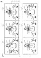
図3は、最適化されていない軌道計画によるロボットの動きを示すタイムライン300を示す。タイムライン300は、第1のマニュピレータ110で第1のテーブル132からボトル130をつかみ上げ、第1のマニュピレータ110から第2のマニュピレータ120へとボトル130を受け渡し、第2のテーブル133にボトルを置くといった、時間に亘るロボット動作を示すフレーム301から306を具備する。以下で示され説明されるように、ロボットの動作は、人間が同じタスクを完了する動作と比較すると、自然に見えない。当然のことながら、図に示された動作は、例示のためにすぎず、ここで説明された実施形態を限定するものではない。
FIG. 3 shows a
フレーム301において、ロボット100は、ボトル130を第1のマニュピレータ110で(例えば第1のマニュピレータの手で)把持する。ロボット100は、指を開いてボトル130近傍の位置へと第1のマニュピレータ110を動かし、次いでその指をボトル130周りで閉じてもよい。フレーム302において、ロボットは、第1のマニュピレータ110及びボトル130を受け渡し位置へと動かし終えている。第1のマニュピレータ110が動いていた間、第2のマニュピレータ120が静止したままだったことに留意されたい。これは人間がこのタスクを完了する仕方ではない。人間は、右腕が受け渡し位置へと物を動かしている間に彼又は彼女の左腕を動かす。フレーム303から305において、ロボット100は、ボトル130を受け取るために第2のマニュピレータ120の指129を開き、第2のマニュピレータ120の指129を閉じ、ボトル130の受け渡しを完了するために第1のマニュピレータ110の指119を開く。フレーム306において、ロボット100は、ボトル130を第2のテーブル133に置くため、第2のマニュピレータ120を第2のテーブル133へと動かされている。以下でより詳細に説明されるように、ここで説明される実施形態は、図3で示された動作より人間的な動作を実現するために、ロボットの動作を並列処理する。
In the
図4は、図3で示されたのと同じボトル130操作タスクを完了するために、ここで説明される1又は複数の実施形態による、最適化された軌道計画を用いるロボット100の動作を示す。フレーム401は、図3のフレーム301の動作と類似したロボット100の動作を示す。しかしながら、フレーム402において、第2のマニュピレータ120は、一方の手から他方の手への物の受け渡しを完了する人間の動作と同じように、ボトル130の受け取りを予測して、第1のマニュピレータ110と同時に動かされる。第1のマニュピレータ110及び第2のマニュピレータ120の両方が同時に動くため、最適化された軌道計画を完了するのにかかる時間は、最適化されていない軌道計画300を完了するのにかかる時間より短い。第2のテーブル132へのボトル130の受け渡しは、図3に対して上述したようにフレーム403から405において実行される(例えば第1のマニュピレータ110から第2のマニュピレータ120へとボトル130を受け渡すためにマニュピレータの指を開閉し、第2のマニュピレータ120を第2のテーブル132へと動かす)。
FIG. 4 illustrates the operation of the
図5Aについて参照すると、図3で示されたロボットの動作による最適化されていない軌道計画500が示されている。軌道計画500は、ロボット100によって受信され(received)てもよく、又は、使用者からの又は外部ソースからの拒否(reject)によりロボット100によって内部的に作成されてもよい。軌道計画500は、時間に亘りマニュピレータの特定の構成要素の動作を示す複数の動作区分を含む。図示された実施形態において、「RH」は、右手構成要素(例えば第1のマニュピレータ110の手構成要素118)を意味し、「RA」は、右腕構成要素を示し、「LH」は、左手構成要素を示し、且つ、「LA」は、左腕構成要素(例えば第2のマニュピレータ120の腕構成要素122)を示す。
Referring to FIG. 5A, a
軌道計画は、ロボットのマニュピレータを制御するアクチュエータ駆動ハードウェアに提供された逆運動学的命令で構成されてもよい。軌道計画は、操作可能にロボットを動かす任意の命令として構成されてもよい。ロボットを制御するために使用される実際の逆運動学的命令又は他の命令は、ここでは説明されない。実施形態は、ロボットのプログラムの任意の特定の形式に限定されるものではない。 The trajectory plan may consist of inverse kinematic instructions provided to the actuator drive hardware that controls the manipulator of the robot. The trajectory plan may be configured as any command that operably moves the robot. The actual inverse kinematic commands or other commands used to control the robot are not described here. Embodiments are not limited to any particular form of robot program.
軌道計画500のそれぞれの動作区分は、図3に示されたロボット100の動作に対応する。動作区分510において、ロボットは、対象物(例えば図3で示されたボトル130)の周りでその右手の指を閉じる。ロボットがその対象物をその右手で固定した後、次いでその右腕を動作区分511の受け渡し位置へと動かす。右腕及び右手が受け渡し位置に至ると、左腕がその動作区分512において受け渡し位置へと駆動され動かされる。動作区分514において、左手及び右手の両方で対象物を把持するために左手が閉じられる。動作区分515において、対象物を解放するため右手が開かれる。次いで、ロボットは、動作区分516でその左腕を目的の位置(例えば第2のテーブル132)へと動かし、次いでその左手を開いてその目的の位置で対象物を完全に解放する。繰り返すが、最適化されていない軌道計画500は、人間的ではないロボットの動作を実行し、実行するのに長い時間間隔がかかる。
Each operation section of the
ここで説明されて図示された実施形態は、受信され又はその他の方法で進展された最適化されていない軌道計画を、可動な動作区分を決定し、次いでその可動な動作区分及び全ての後続の動作区分を時間を戻す方へ移動された位置へと移動させることによって最適化することができる。可動な動作区分及びその可動な動作区分に続いて生じる動作区分を時間を戻す方へ移動させることによって、軌道計画は、分割して割り当てられた元の軌道計画がロボットによって同時に実行されるように並列処理される。最適化された軌道計画は、ロボットによって実行されるより人間的な動作を実現する。 The embodiment described and illustrated herein determines whether or not an unoptimized trajectory plan received or otherwise developed, determines a movable motion segment, then the movable motion segment and all subsequent Optimization can be achieved by moving the motion section to a position that has been moved back in time. By moving the moveable motion segment and the motion segment that follows the moveable motion segment back in time, the trajectory plan is such that the original trajectory plan assigned in segments is executed simultaneously by the robot. Parallel processing. Optimized trajectory planning realizes more human movements performed by the robot.
ここで図5Bを参照すると、第1の可動な動作区分MSは、それぞれの動作区分が適切にラベル付与(labeled)(例えば「RH」、「RA」等)された後に決定される。ある実施形態において、動作区分は、ロボットによって受信されるときに既にラベル付与されている。動作区分は、その動作区分(及びその後続の動作区分)がマニュピレータ間又は操作される対象物との間で競合を生じることなく(例えば対象物の落下)、時間を戻す方へ移動され得る場合に可動とみなされる。1つの実施形態において、それぞれの動作区分は、可動性を決定するため、最後の動作区分(例えば最も右の動作区分517)から最初の動作区分(最も左の動作区分510)へと開始され評価される。 Referring now to FIG. 5B, the first movable motion segment MS is determined after each motion segment is appropriately labeled (eg, “RH”, “RA”, etc.). In some embodiments, motion segments are already labeled when received by the robot. A motion segment can be moved back in time without causing a conflict between the manipulators and the manipulators being operated (and subsequent motion segments) (eg, the fall of the target). Considered movable. In one embodiment, each motion segment is initiated and evaluated from the last motion segment (eg, rightmost motion segment 517) to the first motion segment (leftmost motion segment 510) to determine mobility. Is done.
動作区分は、特定の条件規則を満たした場合に可動として設定されてもよい。1つの実施形態において、動作区分は、評価された特定の動作区分に隣接した前の動作区分が、その特定の動作区分と同じマニュピレータに対応しない場合に可動とみなされる。例えば、特定の動作区分が、「RA」とラベル付与され、その前の動作区分も「RA」とラベル付与されている場合、それは可動とはみなされない。異なる動作を実行しようとしているマニュピレータの構成要素の動作の実行を停止するのは好適ではない。 The motion category may be set as movable when a specific condition rule is satisfied. In one embodiment, a motion section is considered movable if the previous motion section adjacent to the particular motion section evaluated does not correspond to the same manipulator as that particular motion section. For example, if a particular motion category is labeled “RA” and the previous motion category is also labeled “RA”, it is not considered movable. It is not preferred to stop the execution of the manipulator component that is trying to perform a different operation.
可動な動作区分は、連結された動作区分として他の動作区分に連結されたものであってもならない。連結された動作区分は、1又は複数の付加的動作区分と関連した動作区分である。図5Bを参照すると、動作区分514から516は、これらの動作区分の間に、ロボットが右手から左手へと対象物を受け渡すため、連結されたものとみなされる。1又は複数の動作区分514から516が連結された列から外に動かされると、ロボットは対象物を落下させ、又は、一方の手から他方の手へと対象物を受け渡し損ねる。
A movable motion section may not be connected to another motion section as a connected motion section. A concatenated motion segment is a motion segment associated with one or more additional motion segments. Referring to FIG. 5B,
可動な動作区分は、その可動な動作区分と関連した1つの可動な構成要素のみ有するべきでもある。言い換えると、動作区分において腕の二重動作があってはならない。 A movable motion section should also have only one movable component associated with that movable motion section. In other words, there should be no double arm movement in the movement section.
本例示において、動作区分512は、上述した条件を満たすため、図5Bにおいて可動な動作区分MSとして設定される。従って、動作区分512及びその後続の動作区分513から517の全ては、軌道計画500を並列処理するように時間を戻す方へ動かされてもよい。
In this example, the
次いで、可動な動作区分が移動される移動された時間が決定される。可動な動作区分及びその後続の動作区分は、任意の移動された動作区分間で任意の移動されていない動作区分と競合しないように時間を戻す方へ移動されなければならない。1つの実施形態において、複数の移動された時間が決定され、最も短い移動された時間が移動された時間として選択される。それぞれの移動された動作区分は、どれだけ遠くまで時間を戻す方へ移動されるかを決定するように評価されてもよい。可動な動作区分の全ての移動された時間は、マニュピレータの構成要素及び対象物間の競合が回避されるようにするべきである。 Then, the moved time at which the movable motion section is moved is determined. A movable motion segment and its subsequent motion segments must be moved back in time so that they do not compete with any unmoved motion segments between any moved motion segments. In one embodiment, a plurality of moved times are determined and the shortest moved time is selected as the moved time. Each moved motion segment may be evaluated to determine how far it is moved back in time. All moved times of movable motion sections should be such that contention between manipulator components and objects is avoided.
1つの実施形態によれば、特定の動作区分のための可能な移動する時間を決定するために1又は複数の条件規則が適用されてもよい。動作区分は、同じ対象物を操作する他の動作区分上に移動されるべきではない。非現的例示として図5Bを参照すると、対象物Oを操作する動作区分516は、同様に対象物Oを操作する動作区分511と同時に又はその前に生じるように時間を戻す方へ移動されることができない。可動な動作区分512及びその後続を、動作区分516を動作区分511に又は動作区分511の前に移動させる移動された時間へと移動すると、競合を生じさせる。
According to one embodiment, one or more conditional rules may be applied to determine possible travel times for a particular motion segment. The motion section should not be moved over other motion sections that operate on the same object. Referring to FIG. 5B as a non-existent example, the
更に、評価において、特定の動作区分は、同じ構成要素と関連した他の動作区分上に移動されるべきではない。限定するものではないが一例として、動作区分515は、マニュピレータの右手構成要素と関連しており、同じその右手構成要素と関連した動作区分510上に移動されるべきではない。これは、2つの動作区分間で競合を生じさせる。
Furthermore, in an evaluation, a particular motion section should not be moved over other motion sections associated with the same component. By way of example and not limitation,
更に、連結された動作区分は、最適化された軌道計画がロボットによって実行されるときに対象物をうまく操作することを確実とするため、可動な動作区分が開始する時間を越えて移動されるべきではない。本例示において、連結された動作区分514から516は、可動な動作区分512が開始される動作区分511の終端を越えて移動されるべきではない。従って、連結された動作区分514は、動作区分511の終端の前に生じるように移動されるべきではない。
Furthermore, the coupled motion segments are moved beyond the time when the movable motion segment begins to ensure that the object is successfully manipulated when an optimized trajectory plan is executed by the robot. Should not. In this illustration, the linked
図5Cは、上述された条件規則に従って図5Aに示された軌道計画500の並列処理されたバージョンの例示的な最適化された軌道計画500’を示す。図5Cに示されたように、動作区分512は、可動な動作区分として選択された。次いで可動な動作区分512及びその後続の動作区分514から517は、上述された条件規則に従って移動されていない動作区分511が完了するまで連結された動作区分514が開始されないように、移動された時間へとその時間を戻す方へ移動される。従って、移動された動作区分512及び513は、最適化された軌道計画500’が並行処理されるように移動されていない動作区分510及び511と同時に生じる。
FIG. 5C shows an exemplary optimized trajectory plan 500 'of a parallel processed version of the
ここで図6を参照すると、最適化されていない軌道計画のタイムライン600及び最適化された軌道計画のタイムライン600’によるロボット100の動作が示されている。最適化されていない軌道計画のタイムライン600のフレーム601から606が、図3で示された最適化されていない軌道計画のタイムライン300のフレームと同等であることに留意されたい。図6に示されたように、フレーム602及び603によるロボットの動作は、破線領域Aによって示されたような最適化された軌道計画のタイムライン600’の1つのフレーム602/603内に統合されている。従って、ロボット100は、フレーム601においてその右手でボトル130を把持し、次いでその右腕110と左腕120とを同時に結合されたフレーム602/603の受け渡し位置へと動かす。ロボット100は、フレーム604及びフレーム605において右手及び左手間でボトル130の受け渡しを完了し、次いでボトル130をフレーム606において左腕120で第2のテーブル133へと動かす。最適化された軌道計画のタイムライン600’におけるロボットの動作は、最適化されていない軌道計画のタイムライン600におけるロボットの動作よりも、より人間的且つより時間効率の高いものである。
Referring now to FIG. 6, the operation of the
特定の実施形態において、1以上の可動な動作区分が見つけられ、ロボットの動作を更に最適化するために移動されてもよい。更に、ロボットの所望した動作を作成するために様々な条件規則が開発されてもよい。実施形態は、例えば大きなドアを開けるような多関節マニュピレータ動作を必要とする他のロボットのタスクのための軌道計画を最適化してもよい。 In certain embodiments, one or more movable motion segments may be found and moved to further optimize robot motion. In addition, various conditional rules may be developed to create the desired motion of the robot. Embodiments may optimize trajectory planning for other robot tasks that require articulated manipulator motion, such as opening large doors, for example.
ここで当然のことながら、本開示の実施形態は、ロボットが人間的且つ効率的な方法で動くように、多関節マニュピレータ動作を有するロボットの軌道計画を最適化する。ここで説明された実施形態によって最適化された軌道計画に従ったロボットの動作は、ロボットの観察者により予測可能となり得る。例えば、ロボットの観察者は、ロボットが物をつかみ上げて手と手の間でその物を受け渡す両腕を動かすことを予測し得る。ここで説明されたように最適化された軌道計画に従って動くロボットの観察者は、よりロボットを受け入れることができる。 It should be appreciated that embodiments of the present disclosure optimize trajectory planning for robots with articulated manipulator motion so that the robot moves in a human and efficient manner. The behavior of the robot according to the trajectory plan optimized by the embodiments described herein can be predictable by the observer of the robot. For example, a robot observer may expect the robot to pick up an object and move both arms that pass the object between hands. An observer of a robot moving according to an optimized trajectory plan as described herein can accept the robot more.
ここで特定の実施形態が図示され、説明されてきたが、当然のことながら、特許請求された主題の精神及び範囲から逸脱することなく様々な他の変形及び変更がなされてもよい。更に、特許請求された主題の様々な態様がここで説明されてきたが、こうした態様は統合されて実施される必要はない。従って、添付の特許請求の範囲は、特許請求された主題の範囲内にあるこうした全ての変形及び変更を包含する。 While particular embodiments have been illustrated and described herein, it will be appreciated that various other modifications and changes may be made without departing from the spirit and scope of the claimed subject matter. Moreover, although various aspects of the claimed subject matter have been described herein, such aspects need not be implemented in an integrated manner. Accordingly, the appended claims encompass all such variations and modifications that are within the scope of the claimed subject matter.
100 ロボット
102 頭部
104 カメラ
106 移動可能なベース
110 第1のマニュピレータ
112 アーム構成要素
114 前腕
116 手部
118 手構成要素
119 指
120 第2のマニュピレータ
122 アーム構成要素
124 前腕
126 手部
128 手構成要素
129 指
130 ボトル
132 テーブル
133 第2のテーブル
140 プロセッサ
141 ローカルインターフェース
142 入出力ハードウェア
143 メモリ構成要素
144 ロボットデータ/ロジック
145 軌道最適化ロジック
146 ネットワークインターフェースハードウェア
147 アクチュエータ駆動ハードウェア
300 タイムライン
301 フレーム
302 フレーム
303 フレーム
304 フレーム
305 フレーム
306 フレーム
400 タイムライン
401 フレーム
402 フレーム
403 フレーム
404 フレーム
405 フレーム
406 フレーム
500 最適化されていない軌道計画
500’ 最適化された軌道計画
510 動作区分
511 動作区分
512 動作区分
513 動作区分
514 動作区分
515 動作区分
516 動作区分
517 動作区分
600 最適化されていない軌道計画のタイムライン
600’ 最適化された軌道計画のタイムライン
601 フレーム
602 フレーム
603 フレーム
604 フレーム
605 フレーム
606 フレーム
RH 右手構成要素
RA 右腕構成要素
LH 左手構成要素
LA 左腕構成要素
MS 可動な動作区分
DESCRIPTION OF
Claims (20)
複数の順次的動作区分を有する軌道計画を受信することであって、該複数の順次的動作区分の各々が、前記第1のマニュピレータの構成要素又は前記第2のマニュピレータの構成要素に対応し、前記軌道計画が、前記ロボットによって時間間隔に亘り前記第1のマニュピレータ及び前記第2のマニュピレータを順次的に制御するために実行されるように操作可能な軌道計画を受信することと、
前記プロセッサによって自動的に前記軌道計画内で可動な動作区分を決定することと、
前記プロセッサによって自動的に該可動な動作区分及び前記可動な動作区分の後続の動作区分を、前記軌道計画の1又は複数の移動されていない動作区分が1又は複数の移動された動作区分と同時に生じるような移動された時間へと時間を戻す方へ移動させ、それによって最適化された軌道計画を作成することと、
前記第1のマニュピレータの1又は複数の構成要素が前記第2のマニュピレータの1又は複数の構成要素と同時に動かされるように前記最適化された軌道計画によって前記ロボットを制御することと、を含み、
前記動作区分が、当該動作区分が他のいかなる動作区分にも連結されていないときに可動となる、方法。 A method of controlling a robot comprising a processor, a first manipulator and a second manipulator,
Receiving a trajectory plan having a plurality of sequential motion segments, each of the plurality of sequential motion segments corresponding to a component of the first manipulator or a component of the second manipulator; Receiving a trajectory plan operable to be executed by the robot to sequentially control the first manipulator and the second manipulator over a time interval;
Automatically determining movable motion segments within the trajectory plan by the processor;
The moveable motion segment and the motion segment subsequent to the movable motion segment are automatically selected by the processor so that one or more unmoved motion segments of the trajectory plan coincide with one or more moved motion segments. Moving the time back to the time moved as it occurs, thereby creating an optimized trajectory plan;
Controlling the robot with the optimized trajectory plan such that one or more components of the first manipulator are moved simultaneously with the one or more components of the second manipulator;
The method wherein the motion section is movable when the motion section is not coupled to any other motion section.
当該動作区分に隣接した前の動作区分が当該動作区分と同じマニュピレータに対応していないとき、及び、
当該動作区分が前記第1のマニュピレータ又は前記第2のマニュピレータの1つの構成要素にのみ対応するときに可動となる請求項1に記載の方法。 The operation classification is
When the previous motion section adjacent to the motion section does not correspond to the same manipulator as the motion section; and
The method of claim 1, wherein the motion section is movable when it corresponds to only one component of the first manipulator or the second manipulator.
前記動作区分は、当該動作区分と同じ前記第1のマニュピレータ又は前記第2のマニュピレータの構成要素に関連した他の動作区分上に移動されることができず、
2以上の個々の動作区分を有する連結された前記動作区分は、前記可動な動作区分が開始する時間を越えて移動されることができない請求項1に記載の方法。 The motion section cannot be moved onto another motion section that operates the same object,
The motion section cannot be moved onto another motion section associated with the same component of the first manipulator or the second manipulator as the motion section;
The method of claim 1, wherein the linked motion segments having two or more individual motion segments cannot be moved beyond the time at which the movable motion segment begins.
前記最適化された軌道計画を作成するためにコンピュータ実行可能命令を保存し、
前記コンピュータ実行可能命令は、プロセッサによって実行されるとき、前記コンピュータ装置に、
複数の順次的動作区分を有する軌道計画であって、該複数の順次的動作区分の各々が、前記第1のマニュピレータの構成要素又は前記第2のマニュピレータの構成要素に対応し、前記ロボットによって時間間隔に亘り前記第1のマニュピレータ及び前記第2のマニュピレータを順次的に制御するために実行されるように操作可能な軌道計画を受信させ、
前記軌道計画内で可動な動作区分を決定させ、
前記プロセッサによって自動的に、該可動な動作区分及び前記可動な動作区分の後続の動作区分を、前記軌道計画の1又は複数の移動されていない動作区分が1又は複数の移動された動作区分と同時に生じるような移動された時間へと時間を戻す方へ移動させ、それによって前記最適化された軌道計画を作成させ、
前記動作区分が、当該動作区分が他のいかなる動作区分にも連結されていないときに可動となる、コンピュータ可読媒体。 A computer readable medium for use with a computer device to create a trajectory plan optimized to control a robot comprising a first manipulator and a second manipulator ,
Storing computer-executable instructions to create the optimized trajectory plan ;
When the computer-executable instructions are executed by a processor,
A trajectory plan having a plurality of sequential motion sections, each of the plurality of sequential motion sections corresponding to a component of the first manipulator or a component of the second manipulator and timed by the robot. Receiving a trajectory plan operable to be executed to sequentially control the first manipulator and the second manipulator over an interval;
Determining the motion category movable within the trajectory plan;
Automatically, by the processor, the movable motion segment and a subsequent motion segment of the movable motion segment, wherein one or more unmoved motion segments of the trajectory plan are one or more moved motion segments. Move the time back to the time moved to occur at the same time, thereby creating the optimized trajectory plan,
A computer readable medium that is movable when the motion section is not coupled to any other motion section .
当該動作区分に隣接した前の動作区分が当該動作区分と同じマニュピレータに対応していないとき、及び、
当該動作区分が前記第1のマニュピレータ又は前記第2のマニュピレータの1つの構成要素にのみ対応するときに可動となる請求項9に記載のコンピュータ可読媒体。 The operation classification is
When the previous motion section adjacent to the motion section does not correspond to the same manipulator as the motion section; and
The computer-readable medium of claim 9, wherein the computer-readable medium is movable when the motion section corresponds to only one component of the first manipulator or the second manipulator.
前記動作区分は、当該動作区分と同じ前記第1のマニュピレータ又は前記第2のマニュピレータの構成要素に関連した他の動作区分上に移動されることができず、
2以上の個々の動作区分を有する連結された前記動作区分は、前記可動な動作区分が開始する時間を越えて移動されることができない請求項9に記載のコンピュータ可読媒体。 The motion section cannot be moved onto another motion section that operates the same object,
The motion section cannot be moved onto another motion section associated with the same component of the first manipulator or the second manipulator as the motion section;
The computer-readable medium of claim 9, wherein the linked motion segments having two or more individual motion segments cannot be moved beyond the time at which the movable motion segment begins.
1又は複数の第2のマニュピレータアクチュエータと機械的に結合された第2のマニュピレータと、
プロセッサと、
最適化された軌道計画を作成するためにコンピュータ実行可能命令を保存するコンピュータ可読媒体と、を具備するロボットであって、該コンピュータ実行可能命令は、プロセッサによって実行されるとき、当該ロボットに、
複数の順次的動作区分を有する軌道計画であって、該複数の順次的動作区分の各々が、前記第1のマニュピレータの構成要素又は前記第2のマニュピレータの構成要素に対応し、当該ロボットによって時間間隔に亘り前記第1のマニュピレータ及び前記第2のマニュピレータを順次的に制御するために実行されるように操作可能な軌道計画を受信させ、
前記軌道計画内で可動な動作区分を決定させ、
前記プロセッサによって自動的に、該可動な動作区分及び前記可動な動作区分の後続の動作区分を、前記軌道計画の1又は複数の移動されていない動作区分が1又は複数の移動された動作区分と同時に生じるような移動された時間へと時間を戻す方へ移動させ、それによって前記最適化された軌道計画を作成し、
前記第1のマニュピレータの1又は複数の構成要素が前記第2のマニュピレータの1又は複数の構成要素と同時に動かされるように前記最適化された軌道計画を実行させ、
前記動作区分が、当該動作区分が他のいかなる動作区分にも連結されていないときに可動となる、ロボット。 A first manipulator mechanically coupled to one or more first manipulator actuators;
A second manipulator mechanically coupled to one or more second manipulator actuators;
A processor;
A computer-readable medium storing computer-executable instructions for creating an optimized trajectory plan, the computer-executable instructions when executed by a processor,
A trajectory plan having a plurality of sequential motion sections, each of the plurality of sequential motion sections corresponding to a component of the first manipulator or a component of the second manipulator, and time by the robot Receiving a trajectory plan operable to be executed to sequentially control the first manipulator and the second manipulator over an interval;
Determining the motion category movable within the trajectory plan;
Automatically, by the processor, the movable motion segment and a subsequent motion segment of the movable motion segment, wherein one or more unmoved motion segments of the trajectory plan are one or more moved motion segments. Move the time back to the time moved to occur at the same time, thereby creating the optimized trajectory plan,
Performing the optimized trajectory planning such that one or more components of the first manipulator are moved simultaneously with one or more components of the second manipulator;
A robot that is movable when the motion segment is not connected to any other motion segment.
当該動作区分に隣接した前の動作区分が当該動作区分と同じマニュピレータに対応していないとき、及び、
当該動作区分が前記第1のマニュピレータ又は前記第2のマニュピレータの1つの構成要素にのみ対応するときに可動となる請求項16に記載のロボット。 The operation classification is
When the previous motion section adjacent to the motion section does not correspond to the same manipulator as the motion section; and
The robot according to claim 16, wherein the robot is movable when the motion section corresponds to only one component of the first manipulator or the second manipulator.
前記動作区分は、当該動作区分と同じ前記第1のマニュピレータ又は前記第2のマニュピレータの構成要素に関連した他の動作区分上に移動されることができず、
2以上の個々の動作区分を有する連結された前記動作区分は、前記可動な動作区分が開始する時間を越えて移動されることができない請求項16に記載のロボット。 The motion section cannot be moved onto another motion section that operates the same object,
The motion section cannot be moved onto another motion section associated with the same component of the first manipulator or the second manipulator as the motion section;
The robot according to claim 16, wherein the linked motion segments having two or more individual motion segments cannot be moved beyond the time at which the movable motion segment begins.
Applications Claiming Priority (2)
| Application Number | Priority Date | Filing Date | Title |
|---|---|---|---|
| US13/350,179 | 2012-01-13 | ||
| US13/350,179 US8843235B2 (en) | 2012-01-13 | 2012-01-13 | Robots, computer program products, and methods for trajectory plan optimization |
Publications (3)
| Publication Number | Publication Date |
|---|---|
| JP2013144354A JP2013144354A (en) | 2013-07-25 |
| JP2013144354A5 JP2013144354A5 (en) | 2015-06-18 |
| JP6185247B2 true JP6185247B2 (en) | 2017-08-23 |
Family
ID=47631277
Family Applications (1)
| Application Number | Title | Priority Date | Filing Date |
|---|---|---|---|
| JP2013003133A Active JP6185247B2 (en) | 2012-01-13 | 2013-01-11 | Robot, computer program product and method for trajectory planning optimization |
Country Status (3)
| Country | Link |
|---|---|
| US (1) | US8843235B2 (en) |
| EP (1) | EP2614936B1 (en) |
| JP (1) | JP6185247B2 (en) |
Families Citing this family (8)
| Publication number | Priority date | Publication date | Assignee | Title |
|---|---|---|---|---|
| JP5516610B2 (en) * | 2012-01-19 | 2014-06-11 | 株式会社安川電機 | Robot, robot hand, and holding position adjustment method of robot hand |
| EP2685403A3 (en) | 2012-07-09 | 2017-03-01 | Technion Research & Development Foundation Limited | Natural machine interface system |
| JP6387599B2 (en) * | 2013-10-31 | 2018-09-12 | セイコーエプソン株式会社 | Robot, robot system, control apparatus and control method |
| US9701012B1 (en) * | 2014-10-30 | 2017-07-11 | Daniel Theobald | Controlled interaction between a mobile robot and another entity |
| US9910761B1 (en) | 2015-06-28 | 2018-03-06 | X Development Llc | Visually debugging robotic processes |
| CN105511266B (en) * | 2016-01-07 | 2018-09-11 | 无锡信捷电气股份有限公司 | The Delta method for planning track of robot of particle cluster algorithm is searched for based on gravitation |
| US11591170B2 (en) * | 2019-10-25 | 2023-02-28 | Dexai Robotics, Inc. | Robotic systems and methods for conveyance of items |
| CN112847376A (en) * | 2021-02-02 | 2021-05-28 | 广东技术师范大学 | Safe medicine purchasing robot and control method thereof |
Family Cites Families (44)
| Publication number | Priority date | Publication date | Assignee | Title |
|---|---|---|---|---|
| US3985238A (en) | 1973-03-17 | 1976-10-12 | Daikin Kogyo Co., Ltd. | Industrial robot |
| DE2530261C2 (en) | 1974-10-22 | 1986-10-23 | Asea S.p.A., Mailand/Milano | Programming device for a manipulator |
| JPS5840761B2 (en) | 1978-12-20 | 1983-09-07 | 工業技術院長 | Control device for human arm manipulator |
| JPS5766887A (en) | 1980-10-08 | 1982-04-23 | Fujitsu Fanuc Ltd | Hand for industrial robot |
| DE3277087D1 (en) | 1981-09-24 | 1987-10-01 | Hitachi Ltd | Control system for robot hand |
| CA1216343A (en) | 1983-05-02 | 1987-01-06 | Tomohiro Murata | Method and apparatus for controlling an operation sequence of a machinery |
| US5023808A (en) | 1987-04-06 | 1991-06-11 | California Institute Of Technology | Dual-arm manipulators with adaptive control |
| US4762455A (en) | 1987-06-01 | 1988-08-09 | Remote Technology Corporation | Remote manipulator |
| US5038089A (en) | 1988-03-23 | 1991-08-06 | The United States Of America As Represented By The Administrator Of The National Aeronautics And Space Administration | Synchronized computational architecture for generalized bilateral control of robot arms |
| JP2676397B2 (en) | 1989-01-05 | 1997-11-12 | 株式会社エイ・ティ・アール視聴覚機構研究所 | Dynamic trajectory generation method for dynamic system |
| US4974210A (en) | 1989-05-01 | 1990-11-27 | General Electric Company | Multiple arm robot with force control and inter-arm position accommodation |
| US5336982A (en) | 1993-03-24 | 1994-08-09 | The United States Of America As Represented By The Administrator Of The National Aeronautics And Space Administration | Dual-arm generalized compliant motion with shared control |
| JP4765155B2 (en) * | 2000-09-28 | 2011-09-07 | ソニー株式会社 | Authoring system, authoring method, and storage medium |
| JP4119080B2 (en) | 2000-11-17 | 2008-07-16 | 本田技研工業株式会社 | Humanoid robot arm structure |
| WO2002049410A2 (en) | 2000-12-15 | 2002-06-20 | Cyberoptics Corporation | Board align image acquisition device with improved interface |
| DE50208417D1 (en) * | 2001-04-05 | 2006-11-23 | Siemens Ag | ROBOT INTELLIGENCE IN NATURAL ENVIRONMENTS |
| JP3577028B2 (en) * | 2001-11-07 | 2004-10-13 | 川崎重工業株式会社 | Robot cooperative control system |
| WO2003061917A1 (en) | 2002-01-18 | 2003-07-31 | Honda Giken Kogyo Kabushiki Kaisha | Controller of legged mobile robot |
| DE10235943A1 (en) | 2002-08-06 | 2004-02-19 | Kuka Roboter Gmbh | Method and device for the synchronous control of handling devices |
| AU2003257309A1 (en) | 2002-08-13 | 2004-02-25 | Microbotics Corporation | Microsurgical robot system |
| US7386365B2 (en) | 2004-05-04 | 2008-06-10 | Intuitive Surgical, Inc. | Tool grip calibration for robotic surgery |
| DE602004019781D1 (en) | 2003-06-20 | 2009-04-16 | Fanuc Robotics America Inc | MULTIPLE ROBOT ARM TRACKING AND MIRROR JOG |
| JP4592276B2 (en) * | 2003-10-24 | 2010-12-01 | ソニー株式会社 | Motion editing apparatus, motion editing method, and computer program for robot apparatus |
| DE102004026813A1 (en) | 2004-06-02 | 2005-12-29 | Kuka Roboter Gmbh | Method and device for controlling handling devices |
| JP4027350B2 (en) | 2004-06-29 | 2007-12-26 | ファナック株式会社 | Robot standby position return program creation device |
| CN100553901C (en) | 2004-11-17 | 2009-10-28 | Thk株式会社 | Robot joint structure and robot finger |
| JP4382003B2 (en) * | 2005-03-23 | 2009-12-09 | 川崎重工業株式会社 | Robot control apparatus and robot control method |
| US7245975B2 (en) | 2005-04-20 | 2007-07-17 | Parker-Hannifin Corporation | Skew compensation |
| US7860609B2 (en) * | 2005-05-06 | 2010-12-28 | Fanuc Robotics America, Inc. | Robot multi-arm control system |
| JP2007090448A (en) | 2005-09-27 | 2007-04-12 | Honda Motor Co Ltd | Two-dimensional code detecting device, program for it, and robot control information generating device and robot |
| JP4801534B2 (en) | 2006-08-30 | 2011-10-26 | 本田技研工業株式会社 | Robot joint mechanism |
| CN101687321B (en) | 2007-07-05 | 2012-08-08 | 松下电器产业株式会社 | Robot arm control device and control method, robot and control program |
| US7979158B2 (en) * | 2007-07-31 | 2011-07-12 | Rockwell Automation Technologies, Inc. | Blending algorithm for trajectory planning |
| JP2009066685A (en) | 2007-09-11 | 2009-04-02 | Sony Corp | Robot device, and control method for robot device |
| JP5448326B2 (en) | 2007-10-29 | 2014-03-19 | キヤノン株式会社 | Gripping device and gripping device control method |
| JP4249794B1 (en) | 2007-10-29 | 2009-04-08 | ファナック株式会社 | Control device for robot for workpiece transfer |
| JP4560658B2 (en) | 2007-12-10 | 2010-10-13 | 本田技研工業株式会社 | Control device for legged mobile robot |
| JP2010105106A (en) * | 2008-10-29 | 2010-05-13 | Olympus Corp | Production device |
| JP2010240772A (en) * | 2009-04-06 | 2010-10-28 | Seiko Epson Corp | Device and method for controlling robot |
| FR2946160B1 (en) * | 2009-05-26 | 2014-05-09 | Aldebaran Robotics | SYSTEM AND METHOD FOR EDIT AND ORDER BEHAVIOR OF MOBILE ROBOT. |
| KR20110041950A (en) | 2009-10-16 | 2011-04-22 | 삼성전자주식회사 | Teaching and playback method using redundancy resolution control for manipulator |
| JP5528095B2 (en) | 2009-12-22 | 2014-06-25 | キヤノン株式会社 | Robot system, control apparatus and method thereof |
| JP5423441B2 (en) | 2010-02-03 | 2014-02-19 | 株式会社安川電機 | Work system, robot apparatus, and manufacturing method of machine product |
| KR102015307B1 (en) * | 2010-12-28 | 2019-08-28 | 삼성전자주식회사 | Robot and method for controlling the same |
-
2012
- 2012-01-13 US US13/350,179 patent/US8843235B2/en active Active
-
2013
- 2013-01-11 EP EP13151030.7A patent/EP2614936B1/en active Active
- 2013-01-11 JP JP2013003133A patent/JP6185247B2/en active Active
Also Published As
| Publication number | Publication date |
|---|---|
| US8843235B2 (en) | 2014-09-23 |
| JP2013144354A (en) | 2013-07-25 |
| US20130184866A1 (en) | 2013-07-18 |
| EP2614936B1 (en) | 2015-09-16 |
| EP2614936A3 (en) | 2014-07-23 |
| EP2614936A2 (en) | 2013-07-17 |
Similar Documents
| Publication | Publication Date | Title |
|---|---|---|
| JP6185247B2 (en) | Robot, computer program product and method for trajectory planning optimization | |
| JP6073688B2 (en) | Method and computer program product for evaluating grip pattern and robot incorporating the same | |
| JP6039434B2 (en) | Method for generating grip pattern used by robot and computer program product | |
| JP6695170B2 (en) | How to improve robot movement | |
| JP7198831B2 (en) | Autonomous robot with on-demand remote control | |
| JP2013144355A5 (en) | ||
| US10773382B2 (en) | Machine learning methods and apparatus for robotic manipulation and that utilize multi-task domain adaptation | |
| Makris et al. | Intuitive dual arm robot programming for assembly operations | |
| JP2019529135A (en) | Deep reinforcement learning for robot operation | |
| Breyer et al. | Comparing task simplifications to learn closed-loop object picking using deep reinforcement learning | |
| Chang et al. | Planning pre-grasp manipulation for transport tasks | |
| US20210200219A1 (en) | Robot plan online adjustment | |
| US20120165982A1 (en) | Apparatus for planning path of robot and method thereof | |
| WO2020057440A1 (en) | Assembling method, assembling apparatus and assembling device | |
| TW201941081A (en) | Methods and devices for generating robot's action sequence | |
| US20220105625A1 (en) | Device and method for controlling a robotic device | |
| JP2013144354A5 (en) | ||
| US20210060777A1 (en) | Robot planning from process definition graph | |
| Marino et al. | On the problem of moving objects with autonomous robots: A unifying high-level planning approach | |
| WO2022191414A1 (en) | Parameterized waypoint generation on dynamically parented non-static objects for robotic autonomous tasks | |
| JP7452657B2 (en) | Control device, control method and program | |
| US11577392B2 (en) | Splitting transformers for robotics planning | |
| US11747787B2 (en) | Combining transformers for robotics planning | |
| JPWO2021130929A5 (en) | ||
| JP7456552B2 (en) | Information processing device, information processing method, and program |
Legal Events
| Date | Code | Title | Description |
|---|---|---|---|
| A521 | Request for written amendment filed |
Free format text: JAPANESE INTERMEDIATE CODE: A523 Effective date: 20150427 |
|
| A621 | Written request for application examination |
Free format text: JAPANESE INTERMEDIATE CODE: A621 Effective date: 20150427 |
|
| A977 | Report on retrieval |
Free format text: JAPANESE INTERMEDIATE CODE: A971007 Effective date: 20160229 |
|
| A131 | Notification of reasons for refusal |
Free format text: JAPANESE INTERMEDIATE CODE: A131 Effective date: 20160301 |
|
| A601 | Written request for extension of time |
Free format text: JAPANESE INTERMEDIATE CODE: A601 Effective date: 20160601 |
|
| A521 | Request for written amendment filed |
Free format text: JAPANESE INTERMEDIATE CODE: A523 Effective date: 20160831 |
|
| A131 | Notification of reasons for refusal |
Free format text: JAPANESE INTERMEDIATE CODE: A131 Effective date: 20170131 |
|
| A521 | Request for written amendment filed |
Free format text: JAPANESE INTERMEDIATE CODE: A523 Effective date: 20170427 |
|
| TRDD | Decision of grant or rejection written | ||
| A01 | Written decision to grant a patent or to grant a registration (utility model) |
Free format text: JAPANESE INTERMEDIATE CODE: A01 Effective date: 20170627 |
|
| A61 | First payment of annual fees (during grant procedure) |
Free format text: JAPANESE INTERMEDIATE CODE: A61 Effective date: 20170727 |
|
| R150 | Certificate of patent or registration of utility model |
Ref document number: 6185247 Country of ref document: JP Free format text: JAPANESE INTERMEDIATE CODE: R150 |
|
| S111 | Request for change of ownership or part of ownership |
Free format text: JAPANESE INTERMEDIATE CODE: R313117 |
|
| R350 | Written notification of registration of transfer |
Free format text: JAPANESE INTERMEDIATE CODE: R350 |
|
| R250 | Receipt of annual fees |
Free format text: JAPANESE INTERMEDIATE CODE: R250 |
|
| R250 | Receipt of annual fees |
Free format text: JAPANESE INTERMEDIATE CODE: R250 |
|
| R250 | Receipt of annual fees |
Free format text: JAPANESE INTERMEDIATE CODE: R250 |
|
| R250 | Receipt of annual fees |
Free format text: JAPANESE INTERMEDIATE CODE: R250 |