JP7456552B2 - Information processing device, information processing method, and program - Google Patents

Information processing device, information processing method, and program Download PDF

Info

Publication number
JP7456552B2
JP7456552B2 JP2023508219A JP2023508219A JP7456552B2 JP 7456552 B2 JP7456552 B2 JP 7456552B2 JP 2023508219 A JP2023508219 A JP 2023508219A JP 2023508219 A JP2023508219 A JP 2023508219A JP 7456552 B2 JP7456552 B2 JP 7456552B2
Authority
JP
Japan
Prior art keywords
information
robot
input
attribute
unit
Prior art date
Legal status (The legal status is an assumption and is not a legal conclusion. Google has not performed a legal analysis and makes no representation as to the accuracy of the status listed.)
Active
Application number
JP2023508219A
Other languages
Japanese (ja)
Other versions
JPWO2022201314A1 (en
JPWO2022201314A5 (en
Inventor
隼太郎 櫻井
岳大 伊藤
Current Assignee (The listed assignees may be inaccurate. Google has not performed a legal analysis and makes no representation or warranty as to the accuracy of the list.)
NEC Corp
Original Assignee
NEC Corp
Priority date (The priority date is an assumption and is not a legal conclusion. Google has not performed a legal analysis and makes no representation as to the accuracy of the date listed.)
Filing date
Publication date
Application filed by NEC Corp filed Critical NEC Corp
Publication of JPWO2022201314A1 publication Critical patent/JPWO2022201314A1/ja
Publication of JPWO2022201314A5 publication Critical patent/JPWO2022201314A5/en
Application granted granted Critical
Publication of JP7456552B2 publication Critical patent/JP7456552B2/en
Active legal-status Critical Current
Anticipated expiration legal-status Critical

Links

Images

Classifications

    • BPERFORMING OPERATIONS; TRANSPORTING
    • B25HAND TOOLS; PORTABLE POWER-DRIVEN TOOLS; MANIPULATORS
    • B25JMANIPULATORS; CHAMBERS PROVIDED WITH MANIPULATION DEVICES
    • B25J9/00Programme-controlled manipulators
    • B25J9/16Programme controls
    • B25J9/1694Programme controls characterised by use of sensors other than normal servo-feedback from position, speed or acceleration sensors, perception control, multi-sensor controlled systems, sensor fusion
    • B25J9/1697Vision controlled systems
    • BPERFORMING OPERATIONS; TRANSPORTING
    • B25HAND TOOLS; PORTABLE POWER-DRIVEN TOOLS; MANIPULATORS
    • B25JMANIPULATORS; CHAMBERS PROVIDED WITH MANIPULATION DEVICES
    • B25J9/00Programme-controlled manipulators
    • B25J9/16Programme controls
    • B25J9/1656Programme controls characterised by programming, planning systems for manipulators
    • B25J9/1664Programme controls characterised by programming, planning systems for manipulators characterised by motion, path, trajectory planning
    • B25J9/1666Avoiding collision or forbidden zones
    • BPERFORMING OPERATIONS; TRANSPORTING
    • B25HAND TOOLS; PORTABLE POWER-DRIVEN TOOLS; MANIPULATORS
    • B25JMANIPULATORS; CHAMBERS PROVIDED WITH MANIPULATION DEVICES
    • B25J9/00Programme-controlled manipulators
    • B25J9/16Programme controls
    • B25J9/1656Programme controls characterised by programming, planning systems for manipulators
    • B25J9/1664Programme controls characterised by programming, planning systems for manipulators characterised by motion, path, trajectory planning
    • BPERFORMING OPERATIONS; TRANSPORTING
    • B25HAND TOOLS; PORTABLE POWER-DRIVEN TOOLS; MANIPULATORS
    • B25JMANIPULATORS; CHAMBERS PROVIDED WITH MANIPULATION DEVICES
    • B25J9/00Programme-controlled manipulators
    • B25J9/16Programme controls
    • B25J9/1656Programme controls characterised by programming, planning systems for manipulators
    • B25J9/1671Programme controls characterised by programming, planning systems for manipulators characterised by simulation, either to verify existing program or to create and verify new program, CAD/CAM oriented, graphic oriented programming systems
    • BPERFORMING OPERATIONS; TRANSPORTING
    • B25HAND TOOLS; PORTABLE POWER-DRIVEN TOOLS; MANIPULATORS
    • B25JMANIPULATORS; CHAMBERS PROVIDED WITH MANIPULATION DEVICES
    • B25J9/00Programme-controlled manipulators
    • B25J9/16Programme controls
    • B25J9/1679Programme controls characterised by the tasks executed
    • B25J9/1682Dual arm manipulator; Coordination of several manipulators
    • GPHYSICS
    • G05CONTROLLING; REGULATING
    • G05BCONTROL OR REGULATING SYSTEMS IN GENERAL; FUNCTIONAL ELEMENTS OF SUCH SYSTEMS; MONITORING OR TESTING ARRANGEMENTS FOR SUCH SYSTEMS OR ELEMENTS
    • G05B2219/00Program-control systems
    • G05B2219/30Nc systems
    • G05B2219/40Robotics, robotics mapping to robotics vision
    • G05B2219/40392Programming, visual robot programming language

Landscapes

  • Engineering & Computer Science (AREA)
  • Robotics (AREA)
  • Mechanical Engineering (AREA)
  • Manipulator (AREA)
  • Numerical Control (AREA)

Description

本開示は、ロボットの動作計画を修正する処理を行うための情報処理装置、修正システム、情報処理方法及び非一時的なコンピュータ可読媒体に関する。 The present disclosure relates to an information processing device, a modification system, an information processing method, and a non-transitory computer-readable medium for performing processing for modifying a robot's motion plan.

ロボットの最適経路に沿った動作を実機で再現した際、本来人が想定した動作と異なる挙動を示すことがある。例えば、アームの手先が複数の障害物を回避するような最適経路を生成した場合、アームの手先位置以外の部分が衝突する、アームの姿勢変化の大きさによる過負荷がかかってしまうといったことが想定される。また、アームが何かしらの物体を把持したまま動作を行う場合、把持している物体が周囲の人、動物、物体に衝突するといった状況が発生する可能性がある。このようにロボットの最適な動作計画が生成された後、その動作を可視化し、その動作を人が修正できるような機能が必要である。 When a robot's motion along the optimal path is reproduced on an actual machine, it may exhibit behavior that differs from what a human would originally expect. For example, if an optimal path is generated in which the tip of the arm avoids multiple obstacles, parts of the arm other than the tip of the arm may collide, or an overload may be applied due to the magnitude of changes in the arm's posture. is assumed. Further, when the arm performs an operation while gripping an object, a situation may occur in which the gripped object collides with surrounding people, animals, or objects. After the robot's optimal motion plan is generated in this way, there is a need for a function that allows humans to visualize the motion and modify it.

特許文献1には、オフラインプログラミングにより作成したロボット制御プログラムのポジション変数を修正する変数修正方法が開示されている。特許文献2には、パレタイズシステムのように選定入力されたプログラムによりロボットを駆動制御し、このロボットにより所定の製品(以下、ワークという)を取り扱うロボットシステムが開示されている。特許文献3には、ロボットシミュレータを用いて産業用ロボットの動作をシミュレートすることによりプログラミングを行なうロボット動作のシミュレーション方法が開示されている。特許文献4には、ロボットシミュレータを用いて産業用ロボットの動作をシミュレートすることによりプログラミングを行なうロボット動作のシミュレーション方法が開示されている。 Patent Document 1 discloses a variable modification method for modifying position variables of a robot control program created by offline programming. Patent Document 2 discloses a robot system, such as a palletizing system, in which a robot is driven and controlled by a program selected and input, and the robot handles a predetermined product (hereinafter referred to as a work). Patent Document 3 discloses a robot motion simulation method in which programming is performed by simulating the motion of an industrial robot using a robot simulator. Patent Document 4 discloses a robot motion simulation method in which programming is performed by simulating the motion of an industrial robot using a robot simulator.

特開昭62-106507号公報Japanese Unexamined Patent Publication No. 62-106507 特開平07-214485号公報Japanese Patent Application Publication No. 07-214485 特開平08-328632号公報Japanese Patent Application Publication No. 08-328632 特開2013-136123号公報Japanese Patent Application Publication No. 2013-136123

しかしながら、上記特許文献1~4に係る技術は、ロボットの動作シーケンスを修正する際、ロボットの動作空間内の物体に関する属性を適切に取得することができない。こうした属性は、ロボットの動作の制約条件となり得るが、こうした物体に関する属性の一部は、カメラなどの各種センサによっても正確に判断することが難しい場合がある。 However, the techniques according to Patent Documents 1 to 4 cannot appropriately acquire attributes regarding objects within the robot's operation space when modifying the robot's operation sequence. These attributes can serve as constraints on the robot's operation, but some of the attributes related to these objects may be difficult to accurately determine even with various sensors such as cameras.

本開示は、このような問題点を解決するためになされたものであり、ロボットの動作シーケンスを修正するにあたって、ロボットの動作空間内の物体の属性を取得可能な情報処理装置、修正システム、情報処理方法等を提供することを目的の1つとする。 The present disclosure has been made to solve such problems, and provides an information processing device, a correction system, and an information processing device capable of acquiring the attributes of objects in the robot's operation space when modifying the robot's operation sequence. One of the purposes is to provide a processing method, etc.

本開示の第1の態様にかかる情報処理装置は、
ロボットに対する動作シーケンスを修正するための入力を受け付ける入力受付部と、
前記ロボットの動作空間内の物体又は仮想物体の情報を表す物体情報を取得する物体情報取得部と、
前記入力受付部を介した前記入力に基づいて、前記物体又は前記仮想物体に関する属性情報を取得する属性情報取得部と、
を備える。
The information processing device according to the first aspect of the present disclosure includes:
an input reception unit that receives input for modifying the motion sequence for the robot;
an object information acquisition unit that acquires object information representing information about an object or a virtual object in the operating space of the robot;
an attribute information acquisition unit that acquires attribute information regarding the object or the virtual object based on the input via the input reception unit;
Equipped with

本開示の第2の態様にかかる修正システムは、
ロボットの動作シーケンスを表示するシーケンス表示部と、
前記表示結果に対して、ロボットに対する動作シーケンスを修正するための入力を受け付ける入力受付部と、
前記入力に基づいて、前記動作シーケンスの制御信号を前記ロボットに送信する制御信号処理部と、
前記ロボットの動作空間内の物体又は仮想物体の情報を表す物体情報を取得する物体情報取得部と、
前記入力受付部を介した前記入力に基づいて、前記物体又は前記仮想物体に関する属性情報を取得する属性情報取得部と、
前記物体情報と、前記属性情報を結合し、前記物体情報と前記属性情報との組み合わせた属性信号を生成する、属性信号生成部と、
前記属性信号生成部によって生成された、物体と属性の組み合わせの情報を有する前記属性信号を受信し、前記属性信号と、保存している記憶情報に基づいて、ロボットの動作空間を示す抽象状態を修正する修正情報を生成する、属性情報処理部を有する。
The correction system according to the second aspect of the present disclosure includes:
a sequence display section that displays the robot's operation sequence;
an input reception unit that receives input for modifying the operation sequence for the robot in response to the display result;
a control signal processing unit that transmits a control signal for the operation sequence to the robot based on the input;
an object information acquisition unit that acquires object information representing information about an object or a virtual object in the operating space of the robot;
an attribute information acquisition unit that acquires attribute information regarding the object or the virtual object based on the input via the input reception unit;
an attribute signal generation unit that combines the object information and the attribute information to generate an attribute signal that is a combination of the object information and the attribute information;
Receive the attribute signal generated by the attribute signal generation unit and having information on a combination of an object and an attribute, and generate an abstract state indicating an operation space of the robot based on the attribute signal and stored stored information. It has an attribute information processing unit that generates correction information to be corrected.

本開示の第3の態様にかかる情報処理方法は、
ロボットに対する動作シーケンスを修正するための入力を受け付け、
前記ロボットの動作空間内の物体又は仮想物体の情報を表す物体情報を取得し、
前記入力に基づいて、前記物体又は前記仮想物体に関する属性情報を取得する。
The information processing method according to the third aspect of the present disclosure includes:
accepts input for modifying the motion sequence for the robot;
Obtaining object information representing information about an object or a virtual object in the operation space of the robot,
Attribute information regarding the object or the virtual object is acquired based on the input.

本開示の第4の態様にかかるプログラムが格納された非一時的コンピュータ可読媒体は、前記プログラムが
ロボットに対する動作シーケンスを修正するための入力を受け付ける処理と、
前記ロボットの動作空間内の物体又は仮想物体の情報を表す物体情報を取得する処理と、
前記入力に基づいて、前記物体又は前記仮想物体に関する属性情報を取得する処理と、
をコンピュータに実行させる。
A non-transitory computer-readable medium storing a program according to a fourth aspect of the present disclosure includes a process in which the program receives an input for modifying an operation sequence for the robot;
a process of acquiring object information representing information about an object or a virtual object in the operating space of the robot;
a process of acquiring attribute information regarding the object or the virtual object based on the input;
have the computer execute it.

本開示の第5の態様にかかる情報処理装置は、ロボットが動作する空間と、前記空間における物体または仮想物体についての複数の属性候補を表示し、
前記複数の属性候補のうち、選択された属性候補を前記物体または仮想物体の属性に設定する。
An information processing device according to a fifth aspect of the present disclosure displays a space in which a robot operates and a plurality of attribute candidates for objects or virtual objects in the space,
A selected attribute candidate among the plurality of attribute candidates is set as an attribute of the object or virtual object.

本開示により、ロボットの動作空間内の物体の属性を取得可能な情報処理装置、修正システム、及び情報処理方法等を提供することができる。 According to the present disclosure, it is possible to provide an information processing device, a correction system, an information processing method, and the like that can acquire attributes of objects in a robot's operation space.

第1実施形態にかかる情報処理装置の機能ブロック図を示す。1 shows a functional block diagram of an information processing device according to a first embodiment. FIG. 第1実施形態にかかる情報処理方法を示すフローチャートである。4 is a flowchart showing an information processing method according to the first embodiment. 第2実施形態にかかる修正装置の機能ブロック図を示す。FIG. 13 shows a functional block diagram of a correction device according to a second embodiment. 第2実施形態にかかる修正方法を示すフローチャートである。7 is a flowchart showing a correction method according to a second embodiment. ロボット制御システムの構成を示す。The configuration of the robot control system is shown. ロボットコントローラのハードウェア構成を示す。The hardware configuration of the robot controller is shown. シーケンス処理装置のハードウェア構成を示す。The hardware configuration of the sequence processing device is shown. アプリケーション情報のデータ構造の一例を示す。An example of the data structure of application information is shown. ロボットコントローラの機能ブロック図の一例を示す。An example of a functional block diagram of a robot controller is shown. シーケンス処理装置の機能ブロック図の一例を示す。An example of a functional block diagram of a sequence processing device is shown. 動作空間の俯瞰図の一例を示す。An example of an overhead view of the operating space is shown. 第3実施形態におけるシーケンス処理前の計画表示画面の一例を示す。An example of a plan display screen before sequence processing in a third embodiment is shown. 第3実施形態におけるシーケンス処理中の計画表示画面の一例を示す。An example of a plan display screen during sequence processing in the third embodiment is shown. 第3実施形態におけるシーケンス処理後の計画表示画面の一例を示す。An example of a plan display screen after sequence processing in the third embodiment is shown. 第3実施形態におけるシーケンス処理後の計画表示画面の一例を示す。13 shows an example of a plan display screen after sequence processing in the third embodiment. 目標論理式生成部のブロックの一例を示す。An example of a block of the target logical formula generation unit is shown. 第3実施形態においてシーケンス処理装置が実行する修正処理の概要を示すフローチャートの一例である。12 is an example of a flowchart showing an overview of correction processing executed by the sequence processing device in the third embodiment. 第4実施形態におけるシーケンス処理中の計画表示画面の一例を示す。An example of a plan display screen during sequence processing in the fourth embodiment is shown. 第5実施形態におけるシーケンス処理中の計画表示画面の一例を示す。An example of a plan display screen during sequence processing in the fifth embodiment is shown.

以下では、本開示の実施形態について、図面を参照しながら詳細に説明する。各図面において、同一又は対応する要素には同一の符号が付されており、説明の明確化のため、必要に応じて重複説明は省略される。 Embodiments of the present disclosure will be described in detail below with reference to the drawings. In each drawing, the same or corresponding elements are denoted by the same reference numerals, and for clarity of explanation, redundant explanation will be omitted as necessary.

<第1実施形態>
図1は、第1実施形態にかかる情報処理装置の機能ブロック図を示す。
情報処理装置10は、プロセッサおよびメモリ等を含むコンピュータにより実現される。情報処理装置10は、ユーザがロボットに対する動作シーケンスを修正する際に、属性情報を取得するために使用され得る。
<First embodiment>
FIG. 1 shows a functional block diagram of an information processing apparatus according to a first embodiment.
The information processing device 10 is realized by a computer including a processor, memory, and the like. The information processing device 10 can be used to obtain attribute information when a user modifies an operation sequence for a robot.

情報処理装置10は、入力受付部72、物体情報取得部73および属性情報取得部74を備える。入力受付部72は、ロボットに対する動作シーケンスを修正するためのユーザからの入力を受け付ける。入力受付部72は、マウス、キーボード、タッチパネル、スタイラスペン又はマイクロフォンなど入力装置を介して、ユーザからの入力を受け付けることができる。 The information processing device 10 includes an input reception section 72, an object information acquisition section 73, and an attribute information acquisition section 74. The input accepting unit 72 accepts input from the user for modifying the operation sequence for the robot. The input reception unit 72 can receive input from a user via an input device such as a mouse, keyboard, touch panel, stylus pen, or microphone.

物体情報取得部73は、ロボットの動作空間内の物体又は仮想物体に関する情報を取得する。本明細書において、物体は、実際の物体(例えば、実際の障害物、ペットボトル、ドア)を指す。仮想物体は、ロボットの動作空間内に、ユーザによって設定された(例えば、描かれた)仮想的な物体(例えば、仮想障害物)を指す。物体情報取得部73は、入力受付部72を介したユーザからの入力に基づいて、ロボットの動作空間内の物体情報を取得してもよいし、カメラなどの各種センサにより、ロボットの動作空間内の物体情報を取得してもよい。例えば、物体情報取得部73は、画像認識技術を利用して、カメラによる撮影画像から、ロボットの動作空間内の物体情報(例えば、位置情報、形状、物体の種類)を取得することができる。他の実施形態では、例えば、物体又は仮想物体に関する物体情報は、ディスプレイに表示された物体又は仮想物体を、ユーザが選択することによって(すなわち、そのユーザ入力を受け付ける入力受付部72を介して)、当該物体又は仮想物体に関する情報を記憶した記憶部から取得され得る。 The object information acquisition unit 73 acquires information regarding objects or virtual objects within the robot's operating space. As used herein, an object refers to a real object (eg, a real obstacle, a plastic bottle, a door). A virtual object refers to a virtual object (e.g., a virtual obstacle) set (e.g., drawn) by a user in the operating space of the robot. The object information acquisition unit 73 may acquire object information within the robot's operating space based on input from the user via the input receiving unit 72, or may acquire object information within the robot's operating space using various sensors such as a camera. object information may be obtained. For example, the object information acquisition unit 73 can use image recognition technology to acquire object information (for example, position information, shape, and type of object) in the robot's operating space from an image captured by a camera. In other embodiments, for example, object information regarding an object or a virtual object is obtained by the user selecting the object or virtual object displayed on the display (i.e., via the input receiving unit 72 that accepts the user input). , may be acquired from a storage unit that stores information regarding the object or virtual object.

属性情報取得部74は、入力受付部72を介したユーザからの入力に基づいて、物体に関する属性情報を取得する。属性情報は、物体の属性を示す情報であり、より具体的には、物体とロボットとの関係に依存する情報であり得る。いくつかの実施形態では、ロボットが、ユーザによって描かれた仮想物体に接触又は仮想物体を通過することができない場合、仮想物体に「障害物」という属性が付与され、ロボットが、当該仮想物体を経由点として通過することができる場合、当該仮想物体に「経由点」という属性が付与される場合がある。また、他の実施形態では、ロボットが物体の一例であるふたに関連するタスク(例えば、開く)を実行できない場合、ふたに「Closed」という属性が付与され、ロボットがふたに関連するタスク(例えば、開く)を実行できる場合、ふたに「Open」という属性が付与される場合がある。さらに、他の実施形態では、例えば、ロボットが物体を移動させることができない場合、物体には「障害物」という属性情報が付与され、ロボットが物体を移動させることが可能である場合は、物体には、「対象物」という属性情報が付与される場合がある。すなわち、属性情報は、物体に対するロボットの制約条件を規定するものである。こうした属性情報の一部は、カメラなどの各種センサによっても正確に判断できないものを含み得る。 The attribute information acquisition unit 74 acquires attribute information regarding the object based on input from the user via the input reception unit 72. Attribute information is information indicating attributes of an object, and more specifically, may be information that depends on the relationship between the object and the robot. In some embodiments, if the robot is unable to touch or pass through a virtual object drawn by a user, the virtual object is given an attribute of "obstacle" and the robot If the virtual object can be passed through as a waypoint, the attribute of "waypoint" may be given to the virtual object. In other embodiments, if the robot is unable to perform a task related to a lid that is an example of an object (e.g., open), the lid is given an attribute "Closed" and the robot is assigned a task related to the lid (e.g., open). , Open), the attribute "Open" may be given to the lid. Furthermore, in other embodiments, for example, if the robot cannot move the object, the object is given attribute information "obstacle", and if the robot is able to move the object, the object is In some cases, attribute information such as "object" is assigned. That is, the attribute information defines constraints for the robot with respect to the object. Some of this attribute information may include information that cannot be accurately determined even by various sensors such as cameras.

物体情報取得部73により取得された物体又は仮想物体に関する情報に関連付けられた選択可能な複数の属性情報がユーザに提示され、ユーザの選択により、1の属性が取得される。 A plurality of selectable pieces of attribute information associated with information regarding the object or virtual object acquired by the object information acquisition unit 73 are presented to the user, and one attribute is acquired according to the user's selection.

情報処理装置10は、様々な物体情報および物体ごとに関連付けられた選択可能な複数の属性情報を記憶する記憶部を備えてもよいし、ネットワークを介してそのような記憶部と接続されていてもよい。 The information processing device 10 may include a storage unit that stores various object information and a plurality of selectable attribute information associated with each object, or may be connected to such a storage unit via a network. Good too.

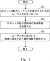
図2は、第1実施形態にかかる情報処理方法を示すフローチャートである。
入力受付部72は、ロボットに対する動作シーケンスを修正するためのユーザからの入力を受け付ける(ステップS1a)。物体情報取得部73は、ロボットの動作空間内の物体又は仮想物体の情報を取得する(ステップS2a)。属性情報取得部74は、ユーザからの入力に基づいて、物体又は仮想物体に関する属性情報を取得する(ステップS3a)。
FIG. 2 is a flowchart showing the information processing method according to the first embodiment.
The input accepting unit 72 accepts input from the user for modifying the operation sequence for the robot (step S1a). The object information acquisition unit 73 acquires information about an object or a virtual object within the robot's operation space (step S2a). The attribute information acquisition unit 74 acquires attribute information regarding the object or virtual object based on input from the user (step S3a).

以上説明した第1実施形態によれば、ロボットに対する動作シーケンスを修正するにあたり、ロボットの動作空間内の物体に関する属性を適切に取得することができる。 According to the first embodiment described above, when modifying the motion sequence for the robot, it is possible to appropriately acquire attributes regarding objects within the motion space of the robot.

<第2実施形態>
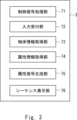
図3は、第2実施形態にかかる修正装置3の機能ブロック図を示す。修正装置3は、プロセッサおよびメモリ等を含むコンピュータにより実現される。修正装置3は、ユーザが、表示されたロボットに対する動作シーケンスを修正するために使用され得る。修正装置3は、後述するロボットコントローラと協働して使用され得る。図3に示すように、修正装置3は、制御信号処理部71、入力受付部72、物体情報取得部73、属性情報取得部74、属性信号生成部75、及びシーケンス表示部76を有する。修正装置3は、第1実施形態に係る情報処理装置10の一例である。
<Second embodiment>
FIG. 3 shows a functional block diagram of the correction device 3 according to the second embodiment. The modification device 3 is realized by a computer including a processor, memory, and the like. The modification device 3 can be used by a user to modify the motion sequence for the displayed robot. The modification device 3 can be used in cooperation with a robot controller described below. As shown in FIG. 3, the correction device 3 includes a control signal processing section 71, an input reception section 72, an object information acquisition section 73, an attribute information acquisition section 74, an attribute signal generation section 75, and a sequence display section 76. The modification device 3 is an example of the information processing device 10 according to the first embodiment.

制御信号処理部71は、ロボットコントローラから制御信号を受信した際に、サブタスクシーケンスの計画を表示するための信号を生成し、シーケンス表示部76に供給する。また、制御信号処理部71は、ロボットコントローラから制御信号を受信した際に、ユーザからの入力を受け付けるための入力受付信号を生成し、入力受付部に供給する。さらに、制御信号処理部71は、入力受付部72からロボットを動作させるための信号を受信すると、サブタスクシーケンスを示す制御信号をロボットに送信する。 When the control signal processing unit 71 receives a control signal from the robot controller, it generates a signal for displaying a subtask sequence plan and supplies it to the sequence display unit 76 . Further, when the control signal processing unit 71 receives a control signal from the robot controller, it generates an input acceptance signal for accepting input from the user, and supplies it to the input acceptance unit. Further, upon receiving a signal for operating the robot from the input receiving unit 72, the control signal processing unit 71 transmits a control signal indicating a subtask sequence to the robot.

シーケンス表示部76は、ロボットコントローラから受け取った制御信号をもとに、サブタスクシーケンスを表示する。 The sequence display section 76 displays the subtask sequence based on the control signal received from the robot controller.

入力受付部72は、入力装置を介したユーザからの入力を受け付ける。入力受付部72は、動作空間内における仮想物体の描画や、物体若しくは仮想物体の選択、物体及び描画した仮想物体の属性の変更といったロボット動作シーケンスの変更に必要な操作をユーザ入力として受け付ける。 The input accepting unit 72 accepts input from a user via an input device. The input receiving unit 72 receives as user input operations necessary for changing the robot operation sequence, such as drawing a virtual object in the action space, selecting an object or virtual object, and changing attributes of the object and the drawn virtual object.

物体情報取得部73は、ユーザが、入力装置を用いて、表示された動作空間内の物体若しくは仮想物体から所望の物体若しくは仮想物体を選択すると、当該物体若しくは仮想物体に関する物体情報を取得する。物体若しくは仮想物体に関する物体情報は、予め、修正装置3の内部又は修正装置3に接続された記憶部に記憶されている。 When the user uses an input device to select a desired object or virtual object from among the objects or virtual objects in the displayed action space, the object information acquisition unit 73 acquires object information regarding the object or virtual object. Object information regarding an object or a virtual object is stored in advance inside the modification device 3 or in a storage unit connected to the modification device 3.

属性情報取得部74は、ユーザが、入力装置を用いて、上記選択された物体についての属性を付与すると、当該物体に関する属性情報を取得する。例えば、前述したように、ユーザが、入力装置を用いて、表示された動作空間内の物体若しくは仮想物体から所望の物体若しくは仮想物体を選択すると、当該所望の物体若しくは仮想物体に関連付けられた複数の属性が表示装置(例えば、ディスプレイ)に選択可能に表示されてもよい。その後、ユーザが、入力装置を用いて、複数の属性から一の属性を選択すると、属性情報取得部74は、当該属性情報を取得する。 When the user uses an input device to assign an attribute to the selected object, the attribute information acquisition unit 74 acquires attribute information regarding the selected object. For example, as described above, when a user uses an input device to select a desired object or virtual object from objects or virtual objects in the displayed operation space, multiple objects associated with the desired object or virtual object are The attributes of may be selectably displayed on a display device (eg, a display). Thereafter, when the user selects one attribute from the plurality of attributes using the input device, the attribute information acquisition unit 74 acquires the attribute information.

属性信号生成部75、前述した物体情報と、属性情報とに基づき、取得した物体の情報と、取得した属性の情報を結合した情報を示す属性信号を生成し、ロボットコントローラに供給する。 The attribute signal generation unit 75 generates an attribute signal indicating information obtained by combining the acquired object information and the acquired attribute information based on the object information and attribute information described above, and supplies the generated attribute signal to the robot controller.

図4は、第2実施形態にかかる修正方法を示すフローチャートである。
シーケンス表示部76は、ロボットコントローラから受け取った制御信号をもとに、ロボットに対する動作シーケンス(サブタスクシーケンス)を表示する(ステップS1b)。入力受付部72は、表示された動作シーケンスに対して、入力装置を介したユーザからの入力を受け付ける(ステップS2b)。物体情報取得部73は、ユーザが、入力装置を用いて、表示された動作空間内の物体若しくは仮想物体から所望の物体若しくは仮想物体を選択すると、当該物体若しくは仮想物体に関する物体情報を取得する(ステップS3b)。属性情報取得部74は、ユーザが、入力装置を用いて、上記選択された物体についての属性を付与すると、当該物体に関する属性情報を取得する(ステップS4b)。属性信号生成部75は、前述した物体情報と、属性情報とに基づき、取得した物体の情報と、取得した属性の情報を結合する(ステップS5b)。属性信号生成部75は、これらを結合した情報を示す属性信号を生成し、ロボットコントローラに供給する。これにより、ロボットコントローラ側で、動作シーケンスの修正が行われる(ステップS6b)。
FIG. 4 is a flowchart showing a correction method according to the second embodiment.
The sequence display unit 76 displays an operation sequence (subtask sequence) for the robot based on the control signal received from the robot controller (step S1b). The input accepting unit 72 accepts input from the user via the input device for the displayed operation sequence (step S2b). When the user uses an input device to select a desired object or virtual object from among the objects or virtual objects in the displayed operation space, the object information acquisition unit 73 acquires object information regarding the object or virtual object ( Step S3b). When the user assigns an attribute to the selected object using the input device, the attribute information acquisition unit 74 acquires attribute information regarding the object (step S4b). The attribute signal generation unit 75 combines the acquired object information and the acquired attribute information based on the object information and attribute information described above (step S5b). The attribute signal generation unit 75 generates an attribute signal indicating the combined information, and supplies it to the robot controller. As a result, the operation sequence is corrected on the robot controller side (step S6b).

以上説明した第2実施形態によれば、ユーザによって付与された物体等についての属性情報に基づいて、ロボットに対する動作シーケンスを修正することができる。 According to the second embodiment described above, it is possible to modify the motion sequence for the robot based on the attribute information about the object etc. given by the user.

<第3実施形態>
(1)システム構成
図5は、第3実施形態に係るロボット制御システム100の構成を示す。
ロボット制御システム100は、主に、ロボットコントローラ1と、入力装置2と、シーケンス処理装置3と、記憶装置4と、ロボット5と、計測装置6と、を備える。
<Third embodiment>
(1) System Configuration FIG. 5 shows the configuration of a robot control system 100 according to the third embodiment.
The robot control system 100 mainly includes a robot controller 1, an input device 2, a sequence processing device 3, a storage device 4, a robot 5, and a measuring device 6.

ロボットコントローラ1は、ロボット5に実行させるタスク(「目的タスク」とも呼ぶ。)が指定された場合に、この目的タスクを、ロボット5が受付可能な単純なタスクのタイムステップ(時間刻み)毎のシーケンスに変換し、当該シーケンスに基づきロボット5を制御する。ロボットコントローラは、本明細書では、情報処理装置とも呼ばれる場合がある。以後では、ロボット5が受付可能な目的タスクを分解した細かいタスク(コマンド)を「サブタスク」とも呼ぶ。 When a task to be executed by the robot 5 (also referred to as a "target task") is specified, the robot controller 1 executes the target task at each time step (time step) of a simple task that the robot 5 can accept. It is converted into a sequence, and the robot 5 is controlled based on the sequence. The robot controller may also be referred to as an information processing device in this specification. Hereinafter, detailed tasks (commands) obtained by breaking down the target task that the robot 5 can accept will also be referred to as "subtasks."

ロボットコントローラ1は、入力装置2、シーケンス処理装置3、記憶装置4、ロボット5、及び計測装置6と電気的に接続している。例えば、ロボットコントローラ1は入力装置2から目的タスクを指定するための入力信号「S1」を受信する。また、ロボットコントローラ1は、入力装置2に対し、ロボット5に実行させるタスクに関する表示を行うための表示信号「S2」を送信する。さらにロボットコントローラ1は、ロボット5の制御に関する制御信号「S3」をロボット5に送信する。例えば、ロボットコントローラ1は、制御信号S3として、ロボット毎に実行させるサブタスクのシーケンス(「サブタスクシーケンス」)とも呼ぶ。)を、シーケンス処理装置3に送信する。さらに、ロボットコントローラ1は、計測装置6から出力信号「S6」を受信する。また、ロボットコントローラ1は、シーケンス処理装置3からロボットの動作空間内の特定の物体又は仮想物体に関する属性の情報に関する属性信号「S5」を受信する。 The robot controller 1 is electrically connected to an input device 2, a sequence processing device 3, a storage device 4, a robot 5, and a measuring device 6. For example, the robot controller 1 receives an input signal “S1” from the input device 2 for specifying a target task. Further, the robot controller 1 transmits a display signal "S2" to the input device 2 for displaying a task to be executed by the robot 5. Furthermore, the robot controller 1 transmits a control signal "S3" to the robot 5 regarding control of the robot 5. For example, the robot controller 1 uses the control signal S3 as a sequence of subtasks (also called a "subtask sequence") to be executed by each robot. ) is transmitted to the sequence processing device 3. Further, the robot controller 1 receives an output signal “S6” from the measuring device 6. The robot controller 1 also receives an attribute signal "S5" from the sequence processing device 3 regarding attribute information regarding a specific object or virtual object within the robot's operation space.

入力装置2は、ユーザが指定した目的タスクに関する入力を受け付けるインターフェースであり、例えば、タッチパネル、ボタン、キーボード、音声入力装置(例えば、マイクロフォン)、パーソナルコンピュータなどが該当する。入力装置2はユーザの入力に基づいて生成した入力信号S1をロボットコントローラ1へ送信する。 The input device 2 is an interface that receives input regarding a target task specified by the user, and includes, for example, a touch panel, buttons, a keyboard, a voice input device (eg, a microphone), a personal computer, and the like. The input device 2 transmits an input signal S1 generated based on user input to the robot controller 1.

シーケンス処理装置3は、ロボットコントローラ1から受け取った制御信号をもとに、サブタスクシーケンスの表示や、動作空間内における仮想物体の描画や、物体及び描画した仮想物体の属性の変更といった、ロボット動作シーケンスの変更に必要な操作をユーザが画面上で行う装置である。シーケンス処理装置3は、修正装置とも呼ばれ、第2実施形態の修正装置の一例である。シーケンス処理装置3は、ロボットコントローラ1から供給される制御信号S3に基づき、サブタスクシーケンスの表示を行い、サブタスクシーケンスの表示後、制御信号S3をロボット5に送信する。また、シーケンス処理装置3は、ロボットの動作空間内における物体の属性を表す属性信号S5をロボットコントローラ1に送信する。入力装置2は、入力部と表示部とを備えるタブレット端末であってもよく、据置型のパーソナルコンピュータであってもよい。 Based on the control signals received from the robot controller 1, the sequence processing device 3 processes the robot operation sequence, such as displaying a subtask sequence, drawing a virtual object in the movement space, and changing the attributes of the object and the drawn virtual object. This is a device that allows the user to perform the operations necessary to change the information on the screen. The sequence processing device 3 is also called a modification device, and is an example of the modification device of the second embodiment. The sequence processing device 3 displays the subtask sequence based on the control signal S3 supplied from the robot controller 1, and transmits the control signal S3 to the robot 5 after displaying the subtask sequence. Further, the sequence processing device 3 transmits an attribute signal S5 representing an attribute of an object in the robot's operation space to the robot controller 1. The input device 2 may be a tablet terminal including an input section and a display section, or may be a stationary personal computer.

記憶装置4はアプリケーション情報記憶部41を有する。アプリケーション情報記憶部41は、目的タスクからサブタスクのシーケンスを生成するために必要なアプリケーション情報を記憶する。アプリケーション情報の詳細は後述する。記憶装置4は、ロボットコントローラ1に接続又は内蔵されたハードディスクなどの外部記憶媒体であってもよく、フラッシュメモリなどの記憶媒体であってもよい。また、記憶装置4は、ロボットコントローラ1とデータ通信を行うサーバ装置であってもよい。この場合、記憶装置4は複数のサーバ装置から構成されてもよい。 The storage device 4 has an application information storage section 41 . The application information storage unit 41 stores application information necessary for generating a sequence of subtasks from a target task. Details of the application information will be described later. The storage device 4 may be an external storage medium such as a hard disk connected to or built into the robot controller 1, or may be a storage medium such as a flash memory. Further, the storage device 4 may be a server device that performs data communication with the robot controller 1. In this case, the storage device 4 may be composed of a plurality of server devices.

ロボット5は、ロボットコントローラ1から送信された制御信号S3に基づき、目的タスクに関連した動作を行う。ロボット5は、例えば、製造現場で利用される組み立てロボット、物流現場で荷物のピッキングを行うロボットである。ロボットアームの場合、単腕でも良いし、2つ以上の腕を持っていてもよい。ロボットアーム以外にも移動ロボットや、移動ロボットとロボットアームを組み合わせたロボットでも良い。 The robot 5 performs operations related to the target task based on the control signal S3 transmitted from the robot controller 1. The robot 5 is, for example, an assembly robot used at a manufacturing site or a robot that picks packages at a logistics site. In the case of a robot arm, it may have a single arm or two or more arms. In addition to the robot arm, it may also be a mobile robot or a robot that combines a mobile robot and a robot arm.

計測装置6は、目的タスクを達成するために、ロボットの動作空間の状態を計測するカメラ、測域センサ、ソナー、またはこれらの組み合わせであり得る1又は複数のセンサである。本実施形態では、計測装置6は、動作空間を撮像する少なくとも1台のカメラを含むものとする。計測装置6は生成した計測信号S6をロボットコントローラ1に供給する。計測信号S6には動作空間内を撮像した画像データが少なくとも含まれる。計測装置6は停止状態を保つ必要はなく、動作中のロボット5や、自走式の移動ロボット、飛行中のドローンに取り付けるセンサであってもよい。また、計測装置6は動作空間内の音を検出するセンサ(例えば、マイクロフォン)を含めてもよい。また、計測装置6は動作空間を撮像するセンサ(例えば、CCD(charge coupled device)又はCMOS(Complementary Metal Oxide Semiconductor)イメージセンサ)であって、動作空間外を含む任意の場所に取り付けられたセンサを含んでもよい。 The measurement device 6 is one or more sensors, which may be a camera, a range sensor, a sonar, or a combination thereof, that measure the state of the robot's operating space in order to accomplish the target task. In this embodiment, the measurement device 6 includes at least one camera that images the operating space. The measuring device 6 supplies the generated measurement signal S6 to the robot controller 1. The measurement signal S6 includes at least image data captured within the operating space. The measuring device 6 does not need to remain in a stopped state, and may be a sensor attached to the robot 5 in operation, a self-propelled mobile robot, or a drone in flight. The measurement device 6 may also include a sensor (eg, a microphone) that detects sound within the operating space. The measuring device 6 is a sensor (for example, a CCD (charge coupled device) or a CMOS (complementary metal oxide semiconductor) image sensor) that captures an image of the operating space, and is a sensor that is attached to any location including outside the operating space. May include.

なお、図5に示すロボット制御システム100の構成は一例であり、当該構成に種々の変更が行われてもよい。例えば複数台のロボット5が存在してもよい。また、ロボット5は複数のロボットアームなどの1つのみまたは2つ以上の制御対象物を備えてもよい。これらの場合であっても、ロボットコントローラ1は、目的タスクに基づき、ロボット5もしくはロボット5が備える制御対象物毎に実行すべきサブタスクシーケンスを生成し、当該サブタスクシーケンスを示す制御信号S3を、制御対象を有するロボット5に送信する。また、計測装置6はロボット5の一部であってもよい。また、入力装置2及びシーケンス処理装置3はロボットコントローラ1に内蔵されるなどの様態により、同一の装置として扱ってもよい。また、ロボットコントローラ1は複数の装置から構成されてもよい。この場合、ロボットコントローラ1を構成する複数の装置は、予め割り当てられた処理を実行するために必要な情報の授受を、これら複数の装置間において行う。また、ロボットコントローラ1とロボット5とは、一体に構成されてもよい。なお、ロボット制御システムの全部又は一部は、ユーザがロボットの動作シーケンスを修正するために使用され得るので、修正システムとも呼ばれる場合がある。 Note that the configuration of the robot control system 100 shown in FIG. 5 is an example, and various changes may be made to the configuration. For example, a plurality of robots 5 may exist. Further, the robot 5 may include only one or two or more control objects, such as a plurality of robot arms. Even in these cases, the robot controller 1 generates a subtask sequence to be executed for each robot 5 or a controlled object provided in the robot 5 based on the target task, and sends a control signal S3 indicating the subtask sequence to the control signal S3. It is sent to the robot 5 that has the target. Further, the measuring device 6 may be a part of the robot 5. Further, the input device 2 and the sequence processing device 3 may be treated as the same device by being built into the robot controller 1 or the like. Furthermore, the robot controller 1 may be composed of a plurality of devices. In this case, the plurality of devices constituting the robot controller 1 exchange information necessary for executing pre-allocated processing. Further, the robot controller 1 and the robot 5 may be integrally configured. Note that all or part of the robot control system may also be referred to as a modification system, since it can be used by a user to modify the robot's motion sequence.

(2)ハードウェア構成
図6は、ロボットコントローラ1のハードウェア構成を示す。ロボットコントローラ1は、ハードウェアとして、プロセッサ11とメモリ12と、インターフェース13とを含む。プロセッサ11、メモリ12及びインターフェース13は、データバス15を介して接続されている。
(2) Hardware Configuration FIG. 6 shows the hardware configuration of the robot controller 1. The robot controller 1 includes a processor 11, a memory 12, and an interface 13 as hardware. Processor 11, memory 12, and interface 13 are connected via data bus 15.

プロセッサ11は、メモリ12に記憶されているプログラムを実行することにより、ロボットコントローラ1の全体の制御を行うコントローラ(演算装置)として機能する。プロセッサ11は、例えば、CPU(Central Processing Unit)、GPU(Graphics Processing Unit)、TPU(Tensor Processing Unit)などのプロセッサである。プロセッサ11は複数のプロセッサから構成されてもよい。The processor 11 functions as a controller (computing device) that performs overall control of the robot controller 1 by executing a program stored in the memory 12. The processor 11 is, for example, a processor such as a CPU (Central Processing Unit), a GPU (Graphics Processing Unit), or a TPU (Tensor Processing Unit). The processor 11 may be composed of multiple processors.

メモリ12はRAM(Random Access Memory)、ROM(Read Only Memory)などの各種のメモリにより構成される。また、メモリ12には、ロボットコントローラ1が特定の処理を実行するためのプログラムが記憶される。また、メモリ12は作業メモリとして使用され、記憶装置4から取得した情報等を一時的に記憶する。また、メモリ12が記憶する情報の一部を、ロボットコントローラ1と通信可能な1又は複数の外部記憶媒体に記憶させても良い。また、ロボットコントローラ1に対して着脱可能な記憶媒体により記憶させても良い。 The memory 12 includes various types of memories such as RAM (Random Access Memory) and ROM (Read Only Memory). Further, the memory 12 stores a program for the robot controller 1 to execute a specific process. Further, the memory 12 is used as a working memory and temporarily stores information etc. acquired from the storage device 4. Further, part of the information stored in the memory 12 may be stored in one or more external storage media that can communicate with the robot controller 1. Further, the information may be stored in a storage medium that is detachable from the robot controller 1.

インターフェース13は、ロボットコントローラ1と他の装置とを電気的に接続するためのインターフェースである。これらのインターフェースは、他の装置とデータの送受信を無線通信により行うためのワイヤレスインターフェースであってもよく、他の装置とケーブル等を用いて有線接続を行うためのハードウェアインターフェースであっても良い。 The interface 13 is an interface for electrically connecting the robot controller 1 and other devices. These interfaces may be wireless interfaces for transmitting and receiving data with other devices through wireless communication, or may be hardware interfaces for making wired connections with other devices using cables, etc. .

なお、ロボットコントローラ1のハードウェア構成は、図6に示す構成に限定されない。例えば、ロボットコントローラ1は、入力装置2、シーケンス処理装置3、記憶装置4、及びスピーカーやイヤホン等の音出力装置と接続又は内蔵しても良い。これらの場合、ロボットコントローラ1は、入出力機能と記憶機能を備えたタブレット端末等であってもよい。 Note that the hardware configuration of the robot controller 1 is not limited to the configuration shown in FIG. 6. For example, the robot controller 1 may be connected to or built in an input device 2, a sequence processing device 3, a storage device 4, and a sound output device such as a speaker or earphone. In these cases, the robot controller 1 may be a tablet terminal or the like having an input/output function and a storage function.

図7はシーケンス処理装置3のハードウェア構成を示す。シーケンス処理装置3は、ハードウェアとして、プロセッサ21と、メモリ22と、インターフェース23と、入力部24aと、表示部24bと、出力部24cとを含む。プロセッサ21、メモリ22及びインターフェース23は、データバス25を介して接続されている。また、インターフェース23には、入力部24aと表示部24bと出力部24cとが接続されている。 FIG. 7 shows the hardware configuration of the sequence processing device 3. The sequence processing device 3 includes, as hardware, a processor 21, a memory 22, an interface 23, an input section 24a, a display section 24b, and an output section 24c. Processor 21, memory 22, and interface 23 are connected via data bus 25. Further, the interface 23 is connected to an input section 24a, a display section 24b, and an output section 24c.

プロセッサ21は、メモリ22に記憶されているプログラムを実行することにより、所定の処理を実行する。プロセッサ21は、例えば、CPU、GPU、TPUなどのプロセッサである。プロセッサ21は、インターフェース23を介して入力部24aが生成した信号を受信することで、取得した属性情報を属性信号S5に変換する処理を行い、インターフェース23を介してロボットコントローラ1に当該属性信号S5を送信する。また、プロセッサ21は、インターフェース23を介してロボットコントローラ1から受信した制御信号S3に基づき、表示部24bまたは出力部24cを、インターフェース23を介して制御することで属性情報を取得することができる。 The processor 21 executes a predetermined process by executing a program stored in the memory 22. The processor 21 is, for example, a processor such as a CPU, GPU, or TPU. The processor 21 receives the signal generated by the input unit 24a via the interface 23, performs a process of converting the acquired attribute information into an attribute signal S5, and transmits the attribute signal S5 to the robot controller 1 via the interface 23. Send. Further, the processor 21 can acquire attribute information by controlling the display section 24b or the output section 24c via the interface 23 based on the control signal S3 received from the robot controller 1 via the interface 23.

メモリ22はRAM、ROMなどの各種のメモリにより構成される。また、メモリ22には、シーケンス処理装置が実行する処理を実行するためのプログラムが記憶される。また、メモリ22はロボットコントローラ1から受信した制御信号S3を一時的に記憶する。 The memory 22 is composed of various types of memories such as RAM and ROM. The memory 22 also stores programs for executing processes executed by the sequence processing device. Furthermore, the memory 22 temporarily stores the control signal S3 received from the robot controller 1.

インターフェース23は、シーケンス処理装置3と他の装置とを電気的に接続するためのインターフェースである。これらのインターフェースは、他の装置とデータの送受信を無線通信により行うためのワイヤレスインターフェースであってもよく、他の装置とケーブル等を用いて有線接続を行うためのハードウェアインターフェースであっても良い。また、インターフェース23は、入力部24a、表示部24b及び出力部24cのインターフェース動作を行う。入力部24aは、ユーザの入力を受け付けるインターフェースであり、例えば、タッチパネル、ボタン、キーボード、音入力装置(例えば、マイクロフォン)などが該当する。表示部24bは、例えば、ディスプレイ、プロジェクタ等であり、プロセッサ21の制御に基づき表示を行う。また、出力部24cは、例えばスピーカであり、プロセッサ21の制御に基づき音出力を行う。The interface 23 is an interface for electrically connecting the sequence processing device 3 to other devices. These interfaces may be wireless interfaces for wirelessly transmitting and receiving data to other devices, or may be hardware interfaces for wired connection to other devices using cables or the like. The interface 23 also performs interface operations for the input unit 24a, the display unit 24b, and the output unit 24c. The input unit 24a is an interface that accepts user input, and corresponds to, for example, a touch panel, a button, a keyboard, a sound input device (for example, a microphone), etc. The display unit 24b is, for example, a display, a projector, etc., and displays based on the control of the processor 21. The output unit 24c is, for example, a speaker, and outputs sound based on the control of the processor 21.

なお、シーケンス処理装置3のハードウェア構成は、図7に示す構成に限定されない。例えば、入力部24a、表示部24b又は出力部24cの少なくともいずれかは、シーケンス処理装置3と電気的に接続する別体の装置として構成されてもよい。また、シーケンス処理装置3は、カメラなどの計測装置と接続してもよく、これらを内蔵してもよい。 Note that the hardware configuration of the sequence processing device 3 is not limited to the configuration shown in FIG. For example, at least one of the input section 24a, the display section 24b, and the output section 24c may be configured as a separate device electrically connected to the sequence processing device 3. Further, the sequence processing device 3 may be connected to a measuring device such as a camera, or may have a built-in measurement device.

(3)アプリケーション情報
次に、アプリケーション情報記憶部41が記憶するアプリケーション情報のデータ構造について説明する。
(3) Application Information Next, the data structure of the application information stored in the application information storage section 41 will be explained.

図8は、アプリケーション情報記憶部41に記憶されるアプリケーション情報のデータ構造の一例を示す。図8に示すように、アプリケーション情報記憶部41は、抽象状態指定情報I1と、制約条件情報I2と、動作限界情報I3と、サブタスク情報I4と、抽象モデル情報I5と、物体モデル情報I6と、属性情報I7と、を含む。 FIG. 8 shows an example of the data structure of application information stored in the application information storage unit 41. As shown in FIG. 8, the application information storage unit 41 stores abstract state specification information I1, constraint information I2, operation limit information I3, subtask information I4, abstract model information I5, object model information I6, Attribute information I7.

抽象状態指定情報I1は、サブタスクシーケンスの生成にあたり定義する必要がある抽象状態を指定する情報である。この抽象状態は、動作空間内における物体の抽象的な状態であって、後述する目標論理式において使用する命題として定められる。例えば、抽象状態指定情報I1は、目的タスクの種類毎に、定義する必要がある抽象状態を指定する。なお、目的タスクは、例えば、ピックアンドプレイス、対象物の持ち直し、対象物の回転などの種々の種類のタスクであってもよい。 The abstract state designation information I1 is information that designates an abstract state that needs to be defined when generating a subtask sequence. This abstract state is an abstract state of an object in the motion space, and is defined as a proposition used in a target logical formula described later. For example, the abstract state specification information I1 specifies an abstract state that needs to be defined for each type of target task. Note that the target task may be various types of tasks, such as pick-and-place, picking up an object, and rotating an object.

制約条件情報I2は、目的タスクを実行する際の制約条件を示す情報である。制約条件情報I2は、例えば、目的タスクがピックアンドプレイスの場合、ロボット5(ロボットアーム)が障害物に接触してはいけないという制約条件、ロボット5(ロボットアーム)同士が接触してはいけないという制約条件などを示す。なお、制約条件情報I2は、目的タスクの種類毎に夫々適した制約条件を記録した情報であってもよい。 The constraint condition information I2 is information indicating the constraint conditions when executing the target task. For example, when the target task is pick and place, the constraint information I2 includes a constraint that the robot 5 (robot arm) must not come into contact with an obstacle, and a constraint that the robots 5 (robot arms) must not come into contact with each other. Indicates constraints, etc. Note that the constraint information I2 may be information in which constraint conditions suitable for each type of target task are recorded.

動作限界情報I3は、ロボットコントローラ1により制御が行われるロボット5の動作限界に関する情報を示す。動作限界情報I3は、例えば、図5に示すロボット5の速度、加速度、角速度などの上限値又は下限値を規定する情報である。The operational limit information I3 indicates information regarding the operational limits of the robot 5 controlled by the robot controller 1. The operational limit information I3 is, for example, information that specifies upper or lower limits of the speed, acceleration, angular velocity, etc. of the robot 5 shown in FIG.

サブタスク情報I4は、ロボット5が受付可能なサブタスクの情報を示す。例えば、目的タスクがピックアンドプレイスの場合には、サブタスク情報I4は、ロボット5のロボットアームの移動であるリーチングと、ロボットアームによる把持であるグラスピングとをサブタスクとして規定することができる。サブタスク情報I4は、目的タスクの種類毎に使用可能なサブタスクの情報を示すものであってもよい。 Subtask information I4 indicates information on subtasks that the robot 5 can accept. For example, when the target task is pick and place, the subtask information I4 can define reaching, which is movement of the robot arm of the robot 5, and grasping, which is gripping by the robot arm, as subtasks. The subtask information I4 may indicate information on usable subtasks for each type of target task.

抽象モデル情報I5は、動作空間におけるダイナミクスを抽象化した抽象モデルに関する情報である。抽象モデルは、後述するように、現実のダイナミクスをハイブリッドシステムにより抽象化したモデルにより表されている。抽象モデル情報I5は、上述のハイブリッドシステムにおけるダイナミクスの切り替わりの条件を示す情報を含む。切り替わりの条件は、例えば、ロボット5により対象物をロボット5が掴んで所定位置に移動させるピックアンドプレイスの場合、対象物はロボット5により把持されなければ移動できないという条件などが該当する。抽象モデル情報I5は、目的タスクの種類毎に適した抽象モデルに関する情報を有している。 The abstract model information I5 is information regarding an abstract model that abstracts the dynamics in the motion space. As will be described later, the abstract model is represented by a model in which the dynamics of reality are abstracted by a hybrid system. Abstract model information I5 includes information indicating conditions for switching dynamics in the above-described hybrid system. The conditions for switching include, for example, in the case of pick-and-place, in which the robot 5 grabs an object and moves it to a predetermined position, the object cannot be moved unless it is gripped by the robot 5. The abstract model information I5 has information regarding an abstract model suitable for each type of target task.

物体モデル情報I6は、計測装置6が生成した計測信号S6から認識すべき動作空間内の各物体の物体モデルに関する情報である。上述の各物体には、例えば、ロボット5、障害物、ロボット5が扱う工具その他の対象物、ロボット5以外の移動体等が該当する。物体モデル情報I6は、例えば、上述した各物体の種類、位置、姿勢、実行中の動作などをロボットコントローラ1が認識するために必要な情報と、各物体の3次元形状を認識するためのCAD(computer-aided design)データなどの3次元形状情報とを含んでいる。前者の情報は、ニューラルネットワークなどの機械学習における学習モデルを学習することで得られた推論器のパラメータを含む。この推論器は、例えば、画像が入力された場合に、当該画像において被写体となる物体の種類、位置、姿勢等を出力するように予め学習される。The object model information I6 is information on the object model of each object in the operating space to be recognized from the measurement signal S6 generated by the measuring device 6. The above-mentioned objects include, for example, the robot 5, obstacles, tools and other objects handled by the robot 5, and moving bodies other than the robot 5. The object model information I6 includes, for example, information necessary for the robot controller 1 to recognize the type, position, posture, and operation being performed of each of the above-mentioned objects, and three-dimensional shape information such as CAD (computer-aided design) data for recognizing the three-dimensional shape of each object. The former information includes parameters of an inference device obtained by learning a learning model in machine learning such as a neural network. For example, when an image is input, this inference device is trained in advance to output the type, position, posture, and other information of the object that is the subject of the image.

属性情報I7は、物体又は仮想物体の属性(例えば、移動不可な障害物又は移動可能な対象物など)を示す情報であり、ロボットコントローラ1における内部処理を追加するための情報である。具体的には、属性情報I7は、物体又は仮想物体とロボットとの関係に依存するものであり、物体又は仮想物体に対するロボットの制約条件である。ロボットコントローラ1は、シーケンス処理装置3が生成した属性信号S5を受信すると、取得した属性に応じて、内部処理を行うことができる。例えば、仮想的な障害物を新たに生成する場合、シーケンス処理装置3において、ユーザが描画した障害物の位置ベクトルの値や、描画後の障害物の数の情報の更新を行う処理を実行することで、動作空間内に新たに障害物が配置された新たな動作空間におけるロボット制御を行うことができる。ロボットの動作空間内の物体を障害物から対象物に変更する別の例では、物体モデル情報I6における識別ラベルを移動不可な障害物から移動可能な対象物に変更する処理を行うことで、これまで障害物だったものを対象物とみなし、対象物とみなされた物体のピックアンドプレイスなどの動作を行うことが可能となる。 The attribute information I7 is information indicating an attribute of an object or a virtual object (for example, an immovable obstacle or a movable object), and is information for adding internal processing in the robot controller 1. Specifically, the attribute information I7 depends on the relationship between the object or virtual object and the robot, and is a constraint on the robot with respect to the object or virtual object. When the robot controller 1 receives the attribute signal S5 generated by the sequence processing device 3, it can perform internal processing according to the acquired attribute. For example, when generating a new virtual obstacle, the sequence processing device 3 executes processing to update the value of the position vector of the obstacle drawn by the user and the information on the number of obstacles after drawing. , the robot can be controlled in a new operating space in which obstacles are newly placed. In another example of changing the object in the robot's operation space from an obstacle to a target object, this can be done by changing the identification label in the object model information I6 from an immovable obstacle to a movable target object. It becomes possible to treat objects that were previously obstacles as targets, and to perform actions such as pick-and-place on objects that are considered targets.

上記属性情報(障害物又は対象物)は、ロボットが、物体を移動させることができるか否かを示す情報である。すなわち、この属性情報は、ロボットと物体との関係に基づくものである。他の実施形態では、後述するように、様々な属性を用いることができる。 The above attribute information (obstacle or target object) is information indicating whether or not the robot can move the object. That is, this attribute information is based on the relationship between the robot and the object. In other embodiments, various attributes may be used, as described below.

このように、様々な属性情報I7が、予め設定され、アプリケーション情報記憶部41に記憶されている。 In this way, various attribute information I7 is set in advance and stored in the application information storage section 41.

なお、アプリケーション情報記憶部41は、上述した情報の他、サブタスクシーケンスの生成処理、制御信号S3に関する種々の情報を記憶してもよい。 In addition to the above-mentioned information, the application information storage unit 41 may also store various information regarding the subtask sequence generation process and the control signal S3.

(4)機能ブロック図
(4-1)ロボットコントローラの機能ブロック図
図9はロボットコントローラ1の機能ブロック図の一例を示す。ロボットコントローラ1のプロセッサ11は、機能的には、抽象状態設定部31と、目標論理式生成部32と、タイムステップ論理式生成部33と、抽象モデル生成部34と、制御入力生成部35と、サブタスクシーケンス生成部36と、属性情報処理部37と、を有する。なお、図8では、各ブロック間で授受が行われるデータの一例が示されているが、これに限定されない。後述する他の機能ブロック図についても同様である。
(4) Functional block diagram (4-1) Functional block diagram of robot controller FIG. 9 shows an example of a functional block diagram of the robot controller 1. The processor 11 of the robot controller 1 functionally includes an abstract state setting section 31, a target logical formula generating section 32, a time step logical formula generating section 33, an abstract model generating section 34, and a control input generating section 35. , a subtask sequence generation section 36, and an attribute information processing section 37. Note that although FIG. 8 shows an example of data exchanged between blocks, the present invention is not limited to this. The same applies to other functional block diagrams to be described later.

抽象状態設定部31は、計測装置6から供給される出力信号S6に基づき、動作空間内における計測結果を示す情報(「計測情報Im」とも呼ぶ)を生成する。具体的には抽象状態設定部31は出力信号S6を受信した場合に物体モデル情報I6等を参照し、目的タスクの実行に関連する動作空間内の各物体の種類(ロボット5、障害物、ロボット5が扱う工具その他の対象物、ロボット5以外の移動体等)及び位置を認識し、この認識結果を計測情報Imとして生成する。また、抽象状態設定部31は、属性情報処理部37から供給される信号を受信した場合、前述の計測情報Imを更新し、属性を考慮した動作空間内の計測結果を示す情報を新たに生成する。抽象状態設定部31は、生成した計測情報Imを、抽象モデル生成部34に供給する。The abstract state setting unit 31 generates information indicating the measurement results in the operating space (also called "measurement information Im") based on the output signal S6 supplied from the measurement device 6. Specifically, when the abstract state setting unit 31 receives the output signal S6, it refers to the object model information I6, etc., recognizes the type and position of each object in the operating space related to the execution of the target task (robot 5, obstacles, tools and other objects handled by the robot 5, moving objects other than the robot 5, etc.), and generates the recognition result as measurement information Im. In addition, when the abstract state setting unit 31 receives a signal supplied from the attribute information processing unit 37, it updates the aforementioned measurement information Im and newly generates information indicating the measurement results in the operating space taking the attributes into consideration. The abstract state setting unit 31 supplies the generated measurement information Im to the abstract model generation unit 34.

また、抽象状態設定部31は、上述の計測情報Im及びアプリケーション情報記憶部41から取得した抽象状態指定情報I1等に基づき、目的タスクを実行時の動作空間内の抽象状態を設定する。この場合、抽象状態設定部31は、各抽象状態に対し、論理式で表すための命題を定義する。抽象状態設定部31は、設定した抽象状態を示す情報(「抽象状態設定情報Is」とも呼ぶ。)を目標論理式生成部32に供給する。 Further, the abstract state setting unit 31 sets an abstract state in the operation space when executing the target task based on the above-mentioned measurement information Im and the abstract state designation information I1 acquired from the application information storage unit 41. In this case, the abstract state setting unit 31 defines a proposition to be expressed by a logical formula for each abstract state. The abstract state setting section 31 supplies information indicating the set abstract state (also referred to as "abstract state setting information Is") to the target logical formula generation section 32.

目標論理式生成部32は、目的タスクに関する入力信号S1を入力装置2から受信した際に、抽象状態設定情報Isに基づき、入力信号S1が示す目的タスクを、最終的な達成状態を表す時相論理の論理式(「目標論理式Ltag」とも呼ぶ。)に変換する。この場合、目標論理式生成部32は、アプリケーション情報記憶部41から制約条件情報I2を参照することで、目的タスクの実行において満たすべき制約条件を、目標論理式Ltagに付加する。そして、目標論理式生成部32は、生成した目標論理式Ltagを、タイムステップ論理式生成部33に供給する。また、目標論理式生成部32は目的タスク実行に必要な入力を受け付けるタスク入力画面を表示するための表示信号S2を生成し、当該表示信号S2を入力装置2に供給する。 When receiving the input signal S1 regarding the target task from the input device 2, the target logical formula generation unit 32 converts the target task indicated by the input signal S1 into a time phase representing the final achievement state based on the abstract state setting information Is. It is converted into a logical formula (also called "target logical formula Ltag"). In this case, the target logical formula generation unit 32 adds the constraint conditions to be satisfied in the execution of the target task to the target logical formula Ltag by referring to the constraint information I2 from the application information storage unit 41. Then, the target logical formula generation unit 32 supplies the generated target logical formula Ltag to the time step logical formula generation unit 33. Further, the target logical formula generation unit 32 generates a display signal S2 for displaying a task input screen that receives input necessary for executing the target task, and supplies the display signal S2 to the input device 2.

タイムステップ論理式生成部33は、目標論理式生成部32から供給された目標論理式Ltagを、各タイムステップでの状態を表した論理式(「タイムステップ論理式Lts」とも呼ぶ。)に変換する。そして、タイムステップ論理式生成部33は、生成したタイムステップ論理式Ltsを、制御入力生成部35に供給する。 The time step logical formula generation unit 33 converts the target logical formula Ltag supplied from the target logical formula generation unit 32 into a logical formula (also referred to as “time step logical formula Lts”) representing the state at each time step. do. The time step logical formula generation unit 33 then supplies the generated time step logical formula Lts to the control input generation unit 35.

抽象モデル生成部34は、計測情報Imと、アプリケーション情報記憶部41が記憶する抽象モデル情報I5とに基づき、動作空間における現実のダイナミクス抽象化したモデルを生成する。 The abstract model generation unit 34 generates a model that abstracts the actual dynamics in the motion space based on the measurement information Im and the abstract model information I5 stored in the application information storage unit 41.

なお、抽象モデルは、

Figure 0007456552000001
と示す。 Note that the abstract model is
Figure 0007456552000001
It shows.

この場合、抽象モデル生成部34は、対象のダイナミクスを連続ダイナミクスと離散ダイナミクスとが混在したハイブリッドシステムとみなし、ハイブリッドシステムに基づく抽象モデルを生成する。抽象モデルの生成方法については後述する。抽象モデル生成部34は、生成した抽象モデルを、制御入力生成部35へ供給する。 In this case, the abstract model generation unit 34 regards the target dynamics as a hybrid system in which continuous dynamics and discrete dynamics are mixed, and generates an abstract model based on the hybrid system. The method for generating the abstract model will be described later. The abstract model generation unit 34 supplies the generated abstract model to the control input generation unit 35.

制御入力生成部35は、タイムステップ論理式生成部33から供給されるタイムステップ論理式Ltsと、抽象モデル生成部34から供給される抽象モデルとを満たし、評価関数を最適化するタイムステップ毎のロボット5への制御入力を決定する。そして、制御入力生成部35は、ロボット5へのタイムステップ毎の制御入力を示す情報(「制御入力情報Ic」とも呼ぶ。)を、サブタスクシーケンス生成部36へ供給する。 The control input generation section 35 satisfies the time step logical formula Lts supplied from the time step logical formula generation section 33 and the abstract model supplied from the abstract model generation section 34, and generates a value for each time step that optimizes the evaluation function. Determine the control input to the robot 5. Then, the control input generation unit 35 supplies information indicating the control input to the robot 5 at each time step (also referred to as “control input information Ic”) to the subtask sequence generation unit 36.

サブタスクシーケンス生成部36は、制御入力生成部35から供給される制御入力情報Icと、アプリケーション情報記憶部41が記憶するサブタスク情報I4とに基づき、サブタスクシーケンスを生成し、サブタスクシーケンスを示す制御信号S3を、シーケンス処理部3へ供給する。 The subtask sequence generation unit 36 generates a subtask sequence based on the control input information Ic supplied from the control input generation unit 35 and the subtask information I4 stored in the application information storage unit 41, and generates a control signal S3 indicating the subtask sequence. is supplied to the sequence processing section 3.

属性情報処理部37は、シーケンス処理装置3から供給される属性信号S5と、アプリケーション情報記憶部41が記憶する属性情報I7と、に基づき、特定の物体又は仮想物体の情報と、特定の属性の組み合わせに応じて、前述の抽象状態を修正するための修正情報Irを生成する。属性情報処理部37は、修正情報Irを、抽象状態設定部31に供給する。 The attribute information processing unit 37 calculates information on a specific object or virtual object and information on a specific attribute based on the attribute signal S5 supplied from the sequence processing device 3 and the attribute information I7 stored in the application information storage unit 41. Modification information Ir for modifying the above-mentioned abstract state is generated according to the combination. The attribute information processing section 37 supplies the modification information Ir to the abstract state setting section 31.

(4-2)シーケンス処理装置の機能ブロック図
図10はシーケンス処理装置3の機能ブロック図の一例である。シーケンス処理装置3のプロセッサ11は、機能的には、制御信号処理部71と、入力受付部72と、物体情報取得部73と、属性情報取得部74と、属性信号生成部75と、シーケンス表示部76と、を有する。なお、図10は、各ブロック間で授受が行われるデータの一例が示されているが、これに限定されない。後述する他の機能ブロック図についても同様である。
(4-2) Functional block diagram of sequence processing device FIG. 10 is an example of a functional block diagram of the sequence processing device 3. The processor 11 of the sequence processing device 3 functionally includes a control signal processing unit 71, an input reception unit 72, an object information acquisition unit 73, an attribute information acquisition unit 74, an attribute signal generation unit 75, and a sequence display It has a section 76. Note that although FIG. 10 shows an example of data exchanged between blocks, the present invention is not limited to this. The same applies to other functional block diagrams to be described later.

制御信号処理部71は、ロボットコントローラ1から制御信号S3を受信した際に、サブタスクシーケンスの計画を表示するための信号Ssを生成し、シーケンス表示部76に供給する。また、制御信号処理部71は、ロボットコントローラ1から制御信号を受信した際に、ユーザからの入力を受け付けるための入力受付信号Siを生成し、入力受付部72に供給する。さらに、制御信号処理部71は、入力受付部72からロボット5を動作させるための信号Saを受信すると、サブタスクシーケンスを示す制御信号S3をロボット5に送信する。 When the control signal processing unit 71 receives the control signal S3 from the robot controller 1, it generates a signal Ss for displaying the subtask sequence plan and supplies it to the sequence display unit 76. Further, when the control signal processing unit 71 receives a control signal from the robot controller 1, it generates an input acceptance signal Si for accepting input from the user, and supplies it to the input acceptance unit 72. Further, upon receiving the signal Sa for operating the robot 5 from the input receiving unit 72, the control signal processing unit 71 transmits a control signal S3 indicating a subtask sequence to the robot 5.

入力受付部72は、制御信号処理部71から入力受付信号Siが供給されると、ユーザによる画面上での操作が可能となる。そして、入力受付部72は、ユーザによって入力された内容を画面上にリアルタイムに表示するための入力表示信号Srを生成し、シーケンス表示部76に送信する。さらに入力受付部72は、ユーザによって、画面上で物体又は仮想物体を選択するという操作が行われた際に、画面上で物体又は仮想物体が選択されたことを示す物体選択信号Soを生成し、物体情報取得部73に供給する。また、入力受付部72は、ユーザによって、画面上で属性を選択するという操作が行われた際に、画面上で属性が選択されたことを示す属性選択信号Spを生成し、属性情報取得部74に供給する。さらに入力受付部72は、ロボット5を動作させるための信号Saを生成し、制御信号処理部71に供給する。 When the input reception unit 72 is supplied with the input reception signal Si from the control signal processing unit 71, it becomes possible for the user to perform operations on the screen. The input reception unit 72 then generates an input display signal Sr for displaying the content input by the user on the screen in real time, and transmits it to the sequence display unit 76. Furthermore, when the user performs an operation to select an object or virtual object on the screen, the input reception unit 72 generates an object selection signal So indicating that the object or virtual object has been selected on the screen. , is supplied to the object information acquisition section 73. Further, when the user performs an operation of selecting an attribute on the screen, the input reception unit 72 generates an attribute selection signal Sp indicating that the attribute has been selected on the screen, and the attribute information acquisition unit 74. Further, the input reception unit 72 generates a signal Sa for operating the robot 5 and supplies it to the control signal processing unit 71.

物体情報取得部73は、入力受付部72から物体選択信号Soが供給されると、物体選択信号Soに対応する物体の情報(例えば、位置ベクトル、物体の種類)を表す物体選択情報Ioを取得し、属性信号生成部75に供給される。例えば、物体の情報のうち、位置ベクトルは、計測装置6により計測され得る。例えば、物体の情報のうち、物体の種類は、計測装置6による撮影画像を画像認識技術により認識することで取得され得る。ユーザによって描かれた仮想物体の情報は、描画情報を記憶した記憶部から取得することができる。 When the object selection signal So is supplied from the input reception unit 72, the object information acquisition unit 73 acquires object selection information Io representing object information (for example, position vector, object type) corresponding to the object selection signal So. and is supplied to the attribute signal generation section 75. For example, among the object information, the position vector may be measured by the measuring device 6. For example, among the object information, the type of the object can be obtained by recognizing an image taken by the measuring device 6 using an image recognition technique. Information about the virtual object drawn by the user can be obtained from a storage unit that stores drawing information.

属性情報取得部74は、入力受付部72から物体選択信号Soが供給されると、物体選択信号Soに対応する属性選択情報Ipを取得し、属性信号生成部75に供給される。属性選択情報は、後述するが、様々な物体に対応して、複数の選択可能な属性情報として、記憶部に記憶されている。 When supplied with the object selection signal So from the input reception section 72, the attribute information acquisition section 74 acquires attribute selection information Ip corresponding to the object selection signal So, and supplies it to the attribute signal generation section 75. As will be described later, the attribute selection information is stored in the storage unit as a plurality of selectable attribute information corresponding to various objects.

属性信号生成部75は、物体選択情報Ioと、属性選択情報Ipとに基づき、取得した物体の情報と、取得した属性の情報を結合した情報を示す属性信号S5を生成する。属性信号S5は、ロボットコントローラ1の属性情報処理部37に供給されることで、「ユーザによって選択された特定の物体又は仮想物体が、特定の属性を付与された」ことを示す情報をロボットコントローラ1に知らせることができる。 The attribute signal generation unit 75 generates an attribute signal S5 indicating information obtained by combining the acquired object information and the acquired attribute information, based on the object selection information Io and the attribute selection information Ip. By being supplied to the attribute information processing unit 37 of the robot controller 1, the attribute signal S5 transmits information indicating that "a specific object or virtual object selected by the user has been given a specific attribute" to the robot controller. 1 can be notified.

(5)ロボットコントローラのブロック毎の処理詳細
次に、図9に示すロボットコントローラ1の機能ブロックごとの処理の詳細について、具体例を用いて説明する。
(5) Details of processing for each block of robot controller Next, details of processing for each functional block of the robot controller 1 shown in FIG. 9 will be explained using a specific example.

(5-1)抽象状態設定部
抽象状態設定部31は、物体モデル情報I6を参照し、動作空間を認識する技術に基づき、計測装置6から供給される出力信号S6を解析し、動作空間内の各物体の計測結果(種類、位置等)を示す計測情報Imを生成する。さらに抽象状態設定部31は、計測情報Imを生成すると共に、動作空間内の抽象状態を設定する。この場合、抽象状態設定部31は、抽象状態指定情報I1を参照し、動作空間内において設定すべき抽象状態を認識する。なお、動作空間内において設定すべき抽象状態は、目的タスクの種類によって異なる。よって、目的タスクの種類毎に設定すべき抽象状態が抽象状態指定情報I1に規定されている場合には、抽象状態設定部31は、入力信号S1により指定された目的タスクに対応する抽象状態指定情報I1を参照し、設定すべき抽象状態を認識する。
(5-1) Abstract state setting unit The abstract state setting unit 31 refers to the object model information I6, analyzes the output signal S6 supplied from the measuring device 6 based on the technology for recognizing the motion space, and Measurement information Im indicating measurement results (type, position, etc.) of each object is generated. Further, the abstract state setting unit 31 generates measurement information Im and sets an abstract state in the motion space. In this case, the abstract state setting unit 31 refers to the abstract state designation information I1 and recognizes the abstract state to be set within the motion space. Note that the abstract state to be set in the action space differs depending on the type of target task. Therefore, when the abstract state to be set for each type of target task is specified in the abstract state designation information I1, the abstract state setting unit 31 sets the abstract state designation corresponding to the target task specified by the input signal S1. The abstract state to be set is recognized by referring to the information I1.

図11はピックアンドプレイスを目的タスクとした場合の動作空間の俯瞰図の一例を示す。図11に示す動作空間には、2つのロボットアーム52a、52bと、4つの物体61a~61dと、障害物62aとが存在している。 FIG. 11 shows an example of a bird's-eye view of the operation space when the target task is pick-and-place. In the operation space shown in FIG. 11, two robot arms 52a and 52b, four objects 61a to 61d, and an obstacle 62a exist.

この場合、ロボットコントローラ1の抽象状態設定部31は、まず、計測装置6から受信した出力信号S6を、物体モデル情報I6等を用いて解析することで、物体61の状態、障害物62aの存在範囲、ゴール地点として設定される領域Gの存在範囲等を認識する。ここでは、抽象状態設定部31は、物体61a~61dの各々の中心の位置ベクトル「x1」~「x4」を、物体61a~61dの位置として認識する。また、抽象状態設定部31は、物体61を把持するロボットハンド53aの位置ベクトル「xr1」と、ロボットハンド53bの位置ベクトル「xr2」とを、ロボットアーム52aとロボットアーム52bの位置として認識する。同様に、抽象状態設定部31は、物体61a~61dの姿勢(図11の例では物体が球状のため不要)等、障害物62aの存在範囲、領域Gの存在範囲等を認識する。なお、抽象状態設定部31は、例えば、障害物62aを直方体とみなし、領域Gを矩形とみなす場合には、障害物62a及び領域Gの各頂点の位置ベクトルを認識する。そして、抽象状態設定部31は、出力信号S6に基づくこれらの認識結果を、計測情報Imとして生成する。 In this case, the abstract state setting unit 31 of the robot controller 1 first analyzes the output signal S6 received from the measuring device 6 using the object model information I6, etc. to determine the state of the object 61 and the presence of the obstacle 62a. The range, the existence range of the area G set as the goal point, etc. are recognized. Here, the abstract state setting unit 31 recognizes the position vectors "x1" to "x4" of the center of each of the objects 61a to 61d as the positions of the objects 61a to 61d. Further, the abstract state setting unit 31 recognizes the position vector "xr1" of the robot hand 53a that grips the object 61 and the position vector "xr2" of the robot hand 53b as the positions of the robot arm 52a and the robot arm 52b. Similarly, the abstract state setting unit 31 recognizes the postures of the objects 61a to 61d (unnecessary in the example of FIG. 11 because the objects are spherical), the existence range of the obstacle 62a, the existence range of the region G, and the like. Note that, for example, when the obstacle 62a is regarded as a rectangular parallelepiped and the region G is regarded as a rectangle, the abstract state setting unit 31 recognizes the position vector of each vertex of the obstacle 62a and the region G. Then, the abstract state setting unit 31 generates these recognition results based on the output signal S6 as measurement information Im.

また、抽象状態設定部31は、抽象状態指定情報I1を参照することで、目的タスクにおいて定義すべき抽象状態を決定する。この場合、抽象状態設定部31は、計測情報Imに基づき、動作空間内に存在する物体及び領域を認識し、当該物体及び領域に関する認識結果(例えば物体及び領域の種類毎の個数)と制約条件情報I2とに基づき、抽象状態を示す命題を定める。 Further, the abstract state setting unit 31 determines the abstract state to be defined in the target task by referring to the abstract state designation information I1. In this case, the abstract state setting unit 31 recognizes the objects and regions existing in the motion space based on the measurement information Im, and the recognition results regarding the objects and regions (for example, the number of each type of objects and regions) and the constraint conditions. Based on the information I2, a proposition indicating an abstract state is determined.

図11の例では、抽象状態設定部31は、計測情報Imにより特定される物体61a~61dに対し、夫々識別ラベル「1」~「4」を付す。また、抽象状態設定部31は、物体「i」(i=1~4)が最終的に載置されるべき目標地点である領域G(破線枠63参照)内に存在するという命題「g」を定義する。また、抽象状態設定部31は、計測情報Imにより特定される障害物62に対して識別ラベル「O」を付し、物体iが障害物Oに干渉しているという命題「o」を定義する。さらに、抽象状態設定部31は、ロボットアーム52同士が干渉するという命題「h」を定義する。 In the example of FIG. 11, the abstract state setting unit 31 assigns identification labels "1" to "4" to the objects 61a to 61d specified by the measurement information Im, respectively. Further, the abstract state setting unit 31 generates a proposition " g ” is defined. Further, the abstract state setting unit 31 attaches an identification label "O" to the obstacle 62 specified by the measurement information Im, and defines a proposition "o i " that the object i is interfering with the obstacle O. do. Further, the abstract state setting unit 31 defines a proposition "h" that the robot arms 52 interfere with each other.

図14は、シーケンス処理装置3によって修正された後の動作空間の俯瞰図を示す。図14に示す動作空間には、2つのロボットアーム52a、52bと、4つの物体61a~61dと、障害物62a、仮想障害物62bとが存在している。図11との違いは仮想障害物62bの存在の有無であり、図14に示すこの仮想障害物62bは、ロボットコントローラ1内の属性情報処理部37で抽象状態を修正するための修正情報Irを生成した際に、ユーザによって描かれた、仮想的な障害物である。この場合、抽象状態設定部31は、修正情報Irが供給されると、仮想障害物62bの実体が実際に動作空間に存在するものとみなし、動作空間内に新たに仮想障害物62bが配置されたかのように、再認識する。 FIG. 14 shows an overhead view of the operating space after it has been modified by the sequence processing device 3. In the operation space shown in FIG. 14 , there are two robot arms 52a and 52b, four objects 61a to 61d, an obstacle 62a, and a virtual obstacle 62b. The difference from FIG. 11 is the presence or absence of a virtual obstacle 62b, and this virtual obstacle 62b shown in FIG. A virtual obstacle drawn by the user when it is generated. In this case, when the abstract state setting unit 31 is supplied with the correction information Ir, it assumes that the entity of the virtual obstacle 62b actually exists in the motion space, and a new virtual obstacle 62b is placed in the motion space. As if, I recognized it again.

この場合、抽象状態設定部31は、修正前の動作空間内の認識に加え、属性情報処理部で生成された、仮想障害物62bの属性を反映した修正情報Irが供給されることで、仮想障害物62bの存在範囲を認識する。そして、抽象状態設定部31は、出力信号S6と、修正情報Irに基づくこれらの認識結果を、計測情報Imとして生成する。 In this case, in addition to the recognition in the motion space before modification, the abstract state setting section 31 is supplied with modification information Ir that reflects the attributes of the virtual obstacle 62b generated by the attribute information processing section. The existence range of the obstacle 62b is recognized. Then, the abstract state setting unit 31 generates the output signal S6 and the recognition results based on the correction information Ir as measurement information Im.

図14の例では、抽象状態設定部31は、計測情報Imにより特定される物体61a~61dに対し、夫々識別ラベル「1」~「4」を付す。また、抽象状態設定部31は、対象物「i」(i=1~4)が最終的に載置されるべき目標地点である領域G(破線枠63参照)内に存在するという命題「g」を定義する。また、抽象状態設定部31は、計測情報Imにより特定される障害物62aに対して識別ラベル「O」を付し、物体iが障害物Oに干渉しているという命題「o」を定義する。また、抽象状態設定部31は、修正情報Irにより特定される仮想障害物62bに対して識別ラベル「Ov」を付し、物体iが仮想障害物Ovに干渉しているという命題「ov」を定義する。さらに、抽象状態設定部31は、ロボットアーム52同士が干渉するという命題「h」を定義する。 In the example of FIG. 14, the abstract state setting unit 31 assigns identification labels "1" to "4" to the objects 61a to 61d specified by the measurement information Im, respectively. The abstract state setting unit 31 also generates a proposition “g” that the object “i” (i=1 to 4) exists in the area G (see broken line frame 63) which is the target point where the object “i” (i=1 to 4) should be finally placed. i ' is defined. Further, the abstract state setting unit 31 attaches an identification label "O" to the obstacle 62a specified by the measurement information Im, and defines a proposition "o i " that the object i is interfering with the obstacle O. do. Further, the abstract state setting unit 31 attaches an identification label "Ov" to the virtual obstacle 62b specified by the correction information Ir, and creates a proposition "ov i " that the object i interferes with the virtual obstacle Ov. Define. Furthermore, the abstract state setting unit 31 defines a proposition "h" that the robot arms 52 interfere with each other.

このように、抽象状態設定部31は、抽象状態指定情報I1を参照することで、定義すべき抽象状態を認識し、当該抽象状態を表す命題(上述の例ではg、o、ov、h)を、物体61の数、ロボットアーム52の数、障害物62の数等に応じてそれぞれ定義する。そして、抽象状態設定部31は、抽象状態を表す命題を示す情報を、抽象状態設定情報Isとして目標論理式生成部32に供給する。 In this way, the abstract state setting unit 31 recognizes the abstract state to be defined by referring to the abstract state specification information I1, and sets the proposition representing the abstract state (in the above example, g i , o i , ov i , h) are respectively defined according to the number of objects 61, the number of robot arms 52, the number of obstacles 62, etc. Then, the abstract state setting section 31 supplies information indicating a proposition representing the abstract state to the target logical formula generation section 32 as abstract state setting information Is.

(5-2)目標論理式生成部
図16は、目標論理式生成部32の機能的なブロック構成図である。図16に示すように、目標論理式生成部32は、機能的には、入力受付部321と、論理式変換部322と、制約条件情報取得部323と、制約条件付加部324とを有する。
(5-2) Target Logical Formula Generation Unit FIG. 16 is a functional block diagram of the target logical formula generation unit 32. As shown in FIG. 16, the target logical formula generation section 32 functionally includes an input reception section 321, a logical formula conversion section 322, a constraint information acquisition section 323, and a constraint addition section 324.

入力受付部321は、目的タスクの種類と、前記ロボットの作業対象となる対象物の最終状態と、を指定する入力信号S1の入力を受け付ける。また、入力受付部321は、これらの入力を受け付けるタスク入力画面の表示信号S2を、ロボットコントローラ1の目標論理式生成部32に送信する。 The input receiving unit 321 receives an input signal S1 specifying the type of target task and the final state of the object to be worked by the robot. In addition, the input accepting unit 321 transmits a display signal S2 of a task input screen that accepts these inputs to the target logical formula generating unit 32 of the robot controller 1.

論理式変換部322は、入力信号S1により指定された目的タスクを、時相論理を用いた論理式に変換する。なお、自然言語で表されたタスクを論理式に変換する方法は、種々の技術が存在する。例えば、図11の例において、「最終的に対象物(i=2)が領域Gに存在する」という目的タスクが与えられたとする。この場合、目標論理式生成部32は、目的タスクを線形論理式(LTL:Linear Temporary Logic)の「eventually」に相当する演算子「◇」と、抽象状態設定部31により定義された命題「g」と用いて、論理式「◇g」を生成する。また、目標論理式生成部32は、演算子「◇」以外の任意の時相論理の演算子(論理積「∧」、論理和「∨」、否定「¬」、論理包含「⇒」、always「□」、next「〇」、until「U」等)を用いて論理式を表現してもよい。また、線形時相論理に限らず、MTL(Metric Temporal Logic)やSTL(Signal Temporal Logic)などの任意の時相論理を用いて論理式を表現しても良い。 The logical formula conversion unit 322 converts the target task specified by the input signal S1 into a logical formula using temporal logic. Note that there are various techniques for converting tasks expressed in natural language into logical expressions. For example, in the example of FIG. 11, it is assumed that a target task of "finally the target object (i=2) exists in area G" is given. In this case, the target logical formula generation unit 32 defines the target task as an operator “◇” corresponding to “eventually” in a linear temporary logic (LTL) and a proposition “g” defined by the abstract state setting unit 31. i ” to generate the logical expression “◇g 2 ”. In addition, the target logical expression generation unit 32 generates an arbitrary temporal logic operator other than the operator “◇” (logical product “∧”, logical sum “∨”, negation “¬”, logical inclusion “⇒”, always A logical expression may be expressed using symbols such as "□", next "〇", until "U", etc.). Furthermore, the logical formula may be expressed using not only linear temporal logic but also any temporal logic such as MTL (Metric Temporal Logic) or STL (Signal Temporal Logic).

制約条件情報取得部323は、アプリケーション情報記憶部41から制約条件情報I2を取得する。なおタスクの種類毎に制約条件情報I2がアプリケーション情報記憶部41に記憶されている場合には、制約条件情報取得部323は、入力信号S1により指定された目的タスクの種類に対応する制約条件情報I2を、アプリケーション情報記憶部41から取得する。 The constraint information acquisition unit 323 acquires the constraint information I2 from the application information storage unit 41. Note that when the constraint information I2 is stored in the application information storage unit 41 for each type of task, the constraint information acquisition unit 323 acquires the constraint information corresponding to the type of target task specified by the input signal S1. I2 is acquired from the application information storage unit 41.

制約条件付加部324は、制約条件情報取得部323が取得した制約条件情報I2が示す制約条件を、論理式変換部322が生成した論理式に付加することで、目標論理式Ltagを生成する。 The constraint addition unit 324 generates the target logical formula Ltag by adding the constraint indicated by the constraint information I2 acquired by the constraint information acquisition unit 323 to the logical formula generated by the logical formula conversion unit 322.

例えば、ピックアンドプレイスに対応する制約条件として「ロボットアーム52同士が干渉しない」、「物体iは障害物Oに干渉しない」の2つが制約条件情報I2に含まれていた場合、制約条件付加部324は、これらの制約条件を論理式に変換する。具体的には、制約条件付加部324は、前述の説明において抽象状態設定部31により定義された命題「oi」及び命題「h」を用いて、上述の2つの制約条件を、夫々以下の論理式に変換する。
□¬h
□¬oi
For example, if the constraint information I2 includes two constraints corresponding to pick-and-place: "robot arms 52 do not interfere with each other" and "object i does not interfere with obstacle O", the constraint condition addition unit 324 converts these constraints into logical expressions. Specifically, the constraint addition unit 324 uses the proposition “o i ” and the proposition “h” defined by the abstract state setting unit 31 in the above explanation to apply the above two constraint conditions to the following, respectively. Convert to logical expression.
□¬h
i □¬o i

よって、この場合、制約条件付加部324は、「最終的に対象物(i=2)が領域Gに存在する」という目的タスクに対応する論理式「◇g」に、これらの制約条件の論理式を付加することで、以下の目標論理式Ltagを生成する。
(◇g2)∧(□¬h)∧(∧□¬oi
Therefore, in this case, the constraint addition unit 324 adds these constraints to the logical expression "◇g 2 " corresponding to the objective task "Finally, the object (i=2) exists in the area G". By adding the logical formula, the following target logical formula Ltag is generated.
(◇ g2 )∧(□¬h)∧(∧ i □¬o i )

なお、実際には、ピックアンドプレイスに対応する制約条件は、上述した2つに限られず、「ロボットアーム52が同じ対象物を掴まない」、「対象物同士が接触しない」などの制約条件が存在する。また、図14のような修正後の動作空間における制約条件には「物体iは仮想障害物Ovに干渉しない」といった制約条件が含まれる。このような制約条件についても同様に、制約条件情報I2に記憶され、目標論理式Ltagに反映される。 In reality, the constraint conditions corresponding to pick-and-place are not limited to the two mentioned above, but may include constraints such as "the robot arms 52 do not grasp the same object" and "the objects do not come into contact with each other." exist. Further, the constraint conditions in the modified motion space as shown in FIG. 14 include a constraint condition such as "object i does not interfere with virtual obstacle Ov". Such constraints are similarly stored in the constraint information I2 and reflected in the target logical formula Ltag.

(5-3)タイムステップ論理式生成部
タイムステップ論理式生成部33は、目的タスクを完了するタイムステップ数(「目標タイムステップ数」とも呼ぶ。)を定め、目標タイムステップ数で目標論理式Ltagを満たすような各タイムステップでの状態を表す命題の組み合わせを定める。通常、複数の組み合わせが、存在するため、タイムステップ論理式生成部33は、これらの組み合わせを論理和により結合した論理式を、タイムステップ論理式Ltsとして生成する。上述の組み合わせは、ロボット5に命令する動作シーケンスを表す論理式の候補となり、以後では「候補φ」とも呼ぶ。
(5-3) Time step logical formula generation unit The time step logical formula generation unit 33 determines the number of time steps (also referred to as “target time step number”) to complete the target task, and formulates a target logical formula using the target number of time steps. A combination of propositions representing the state at each time step that satisfies Ltag is determined. Since there are usually a plurality of combinations, the time step logical formula generation unit 33 generates a logical formula in which these combinations are combined by a logical sum as the time step logical formula Lts. The above-mentioned combination becomes a candidate for a logical expression representing an operation sequence to be commanded to the robot 5, and will also be referred to as a "candidate φ" hereinafter.

ここで図11の説明において例示した「最終的に対象物(i=2)が領域Gに存在する」という目的タスクが設定された場合のタイムステップ論理式生成部33(図9)の処理の具体例について説明する。 Here, we will explain the processing of the time step logical formula generation unit 33 (FIG. 9) when the objective task "finally the target object (i=2) exists in area G" is set as illustrated in the explanation of FIG. 11. A specific example will be explained.

この場合、タイムステップ論理式生成部33は、目標論理式Ltagとして、「(◇g)∧(□¬h)∧(∧□¬oi)」が目標論理式生成部32から供給される。この場合、タイムステップ論理式生成部33は、命題「g」をタイムステップの概念を含むように拡張した命題「gi,k」を用いる。ここで命題「gi,k」は「タイムステップkで物体iが領域Gに存在する」という命題である。ここで、目標タイムステップ数を「3」とした場合、目標論理式Ltagは、以下のように書き換えられる。
(◇g2,3)∧(∧k=1,2,3□¬h)∧(∧i,k1,2,3□¬oi
In this case, the time step logical formula generation unit 33 receives “(◇g 2 )∧(□¬h)∧(∧ i □¬o i )” from the target logical formula generation unit 32 as the target logical formula Ltag. Ru. In this case, the time step logical formula generation unit 33 uses a proposition "g i ,k " which is an extension of the proposition "g i " to include the concept of a time step. Here, the proposition "g i,k " is the proposition "object i exists in region G at time step k". Here, when the target number of time steps is "3", the target logical formula Ltag is rewritten as follows.
(◇g 2,3 )∧(∧ k=1,2,3 □¬h k )∧(∧ i,k = 1,2,3 □¬o i )

また、◇g2,3は以下の式に示すように書き換えることが可能である。 Moreover, ◇g 2, 3 can be rewritten as shown in the following formula.
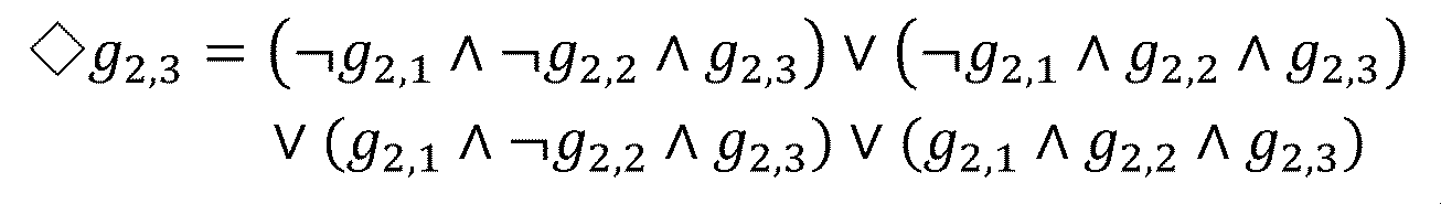
Figure 0007456552000002

このとき、上述した目標論理式Ltagは、以下に示す4つの候補「φ」~「φ」の論理和(φ∨φ∨φ∨φ)により表される。 At this time, the target logical formula Ltag described above is expressed by the logical sum (φ 1 ∨φ 2 ∨φ 3 ∨φ 4 ) of the four candidates “φ 1 ” to “φ 4 ” shown below.
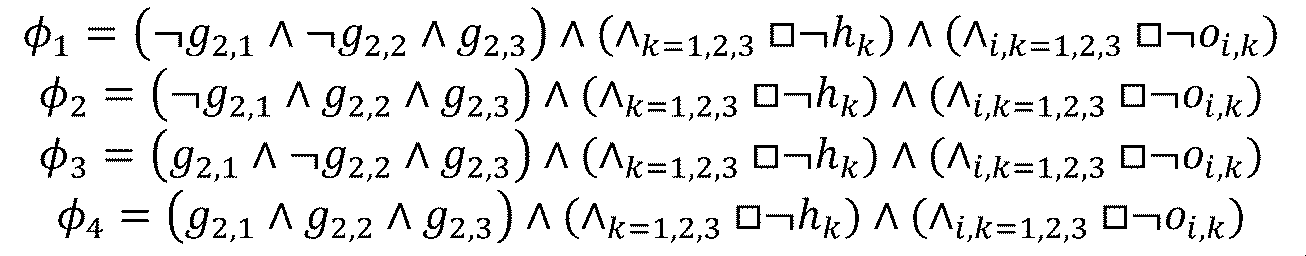
Figure 0007456552000003

よって、タイムステップ論理式生成部33は、4つの候補φ~φの論理和をタイムステップ論理式Ltsとして定める。この場合、タイムステップ論理式Ltsは、4つの候補φ~φの少なくともいずれかが真となる場合に真となる。 Therefore, the time step logical formula generation unit 33 determines the logical sum of the four candidates φ 1 to φ 4 as the time step logical formula Lts. In this case, the time step logical formula Lts becomes true when at least one of the four candidates φ 1 to φ 4 is true.

好適には、タイムステップ論理式生成部33は、生成された候補に対し、動作限界情報I3を参照することで、実現可能性を判定し、実現不可と判定した候補を除外するとよい。例えば、タイムステップ論理式生成部33は、動作限界情報I3に基づき、ロボットハンドが1タイムステップ当たりに移動可能な距離を認識する。また、タイムステップ論理式生成部33は、計測情報Imが示す各対象物及びロボットハンドの位置ベクトルに基づき、移動対象となる対象物(i=2)とロボットハンドとの距離を認識する。 Preferably, the time step logical formula generation unit 33 determines the feasibility of the generated candidates by referring to the operation limit information I3, and excludes candidates determined to be unfeasible. For example, the time step logical formula generation unit 33 recognizes the distance that the robot hand can move per one time step based on the operation limit information I3. Further, the time step logical formula generation unit 33 recognizes the distance between the object to be moved (i=2) and the robot hand based on the position vectors of each object and the robot hand indicated by the measurement information Im.

例えば、タイムステップ論理式生成部33は、ロボットハンド53a及びロボットハンド53bがいずれも、対象物(i=2)との距離が1タイムステップ当たりの移動可能距離よりも長いと判定した場合、上述の候補φ及び候補φは実現不可と判定する。この場合、タイムステップ論理式生成部33は、候補φ及び候補φをタイムステップ論理式Ltsから除外する。この場合、タイムステップ論理式Ltsは、候補φと候補φとの論理和(φ∨φ)となる。 For example, when it is determined that the distance between the robot hand 53a and the robot hand 53b is longer than the movable distance per time step for both the robot hand 53a and the robot hand 53b, the time step logical formula generation unit 33 Candidates φ 3 and φ 4 are determined to be unfeasible. In this case, the time step logical formula generation unit 33 excludes candidate φ 3 and candidate φ 4 from the time step logical formula Lts. In this case, the time step logical formula Lts is the logical sum (φ 1 ∨φ 2 ) of the candidate φ 1 and the candidate φ 2 .

このように、タイムステップ論理式生成部33は、動作限界情報I3を参照して実現不可能な候補をタイムステップ論理式Ltsから除外することで、後段の処理部の処理負荷を好適に低減させることができる。 In this way, the time step logical formula generation unit 33 refers to the operation limit information I3 and excludes unfeasible candidates from the time step logical formula Lts, thereby suitably reducing the processing load on the subsequent processing unit. be able to.

次に、目標タイムステップ数の設定方法について補足説明する。 Next, a supplementary explanation will be given of the method for setting the target time step number.

タイムステップ論理式生成部33は、例えば、ユーザ入力により指定された作業の見込み時間に基づき、目標タイムステップ数を決定する。この場合、タイムステップ論理式生成部33は、メモリ12又は記憶装置4に記憶された、1タイムステップ当たりの時間幅の情報に基づき、上述の見込み時間から目標タイムステップ数を算出する。他の例では、タイムステップ論理式生成部33は、目的タスクの種類毎に適した目標タイムステップ数を対応付けた情報を予めメモリ12又は記憶装置4に記憶しておき、当該情報を参照することで、実行すべき目的タスクの種類に応じた目標タイムステップ数を決定する。The time step logical formula generating unit 33 determines the target number of time steps based on, for example, the expected time of the task specified by user input. In this case, the time step logical formula generating unit 33 calculates the target number of time steps from the expected time based on the information on the time width per time step stored in the memory 12 or the storage device 4. In another example, the time step logical formula generating unit 33 stores in advance in the memory 12 or the storage device 4 information that associates the target number of time steps appropriate for each type of target task, and determines the target number of time steps according to the type of target task to be executed by referring to the information.

好適には、タイムステップ論理式生成部33は、目標タイムステップ数を所定の初期値に設定する。そして、タイムステップ論理式生成部33は、制御入力生成部35が制御入力を決定できるタイムステップ論理式Ltsが生成されるまで、目標タイムステップ数を徐々に増加させる。この場合、タイムステップ論理式生成部33は、設定した目標タイムステップ数により制御入力生成部35が最適化処理を行った結果、最適解を導くことができなかった場合、目標タイムステップ数を所定数(1以上の整数)だけ加算する。 Preferably, the time step logical formula generation unit 33 sets the target time step number to a predetermined initial value. Then, the time step logical formula generation unit 33 gradually increases the target time step number until the time step logical formula Lts with which the control input generation unit 35 can determine the control input is generated. In this case, if the control input generation unit 35 performs optimization processing using the set target number of time steps and is unable to derive an optimal solution, the time step logical formula generation unit 33 sets the target number of time steps to a predetermined number. Add only a number (an integer greater than or equal to 1).

このとき、タイムステップ論理式生成部33は、目標タイムステップ数の初期値を、ユーザが見込む目的タスクの作業時間に相当するタイムステップ数よりも小さい値に設定するとよい。これにより、タイムステップ論理式生成部33は、不必要に大きな目標タイムステップ数を設定することを好適に抑制する。 At this time, the time step logical formula generation unit 33 preferably sets the initial value of the target number of time steps to a value smaller than the number of time steps corresponding to the work time of the target task expected by the user. Thereby, the time step logical formula generation unit 33 suitably suppresses setting an unnecessarily large target time step number.

上述の目標タイムステップ数の設定方法による効果について補足説明する。一般に、目標タイムステップ数が大きいほど、制御入力生成部35による最適化処理において最適解が存在する可能性が高くなる一方で、最低化処理等の処理負荷や目的タスク達成に要するロボット5の所要時間が長くなる。以上を勘案し、タイムステップ論理式生成部33は、目標タイムステップ数の初期値を小さい値とし、制御入力生成部35の最適化処理における解が存在するまで徐々に目標タイムステップ数を大きくする。これにより、タイムステップ論理式生成部33は、制御入力生成部35の最適化処理における解が存在する範囲において可能な限り少ない目標タイムステップ数を設定することができる。従って、この場合、最適化処理における処理負荷の低減、及び、目的タスク達成に要するロボット5の所要時間の短縮を実現することができる。 A supplementary explanation will be given of the effect of the method for setting the target time step number described above. In general, the larger the target time step number, the higher the possibility that an optimal solution will exist in the optimization process by the control input generation unit 35, but the processing load such as the minimization process and the robot 5 required to achieve the target task increase. It takes longer. Taking the above into consideration, the time step logical formula generation unit 33 sets the initial value of the target time step number to a small value, and gradually increases the target time step number until a solution exists in the optimization process of the control input generation unit 35. . Thereby, the time step logical formula generation unit 33 can set the target number of time steps as small as possible within the range where a solution exists in the optimization process of the control input generation unit 35. Therefore, in this case, it is possible to reduce the processing load in the optimization process and shorten the time required for the robot 5 to accomplish the target task.

(5-4)抽象モデル生成部
抽象モデル生成部34は、計測情報Imと、抽象モデル情報I5とに基づき、抽象モデルを生成する。ここで、抽象モデル情報I5には、目的タスクの種類毎に、抽象モデルの生成に必要な情報が記録されている。例えば、目的タスクがピックアンドプレイスの場合には、対象物の位置や数、対象物を置く領域の位置、ロボット5の台数(又はロボットアーム52の数)等を特定しない汎用的な形式の抽象モデルが抽象モデル情報I5に記録されている。そして、抽象モデル生成部34は、抽象モデル情報I5に記録された汎用的な形式の抽象モデルに対し、計測情報Imが示す対象物の位置や数、対象物を置く領域の位置、ロボット5の台数等を反映することで、抽象モデルΣを生成する。
(5-4) Abstract Model Generation Unit The abstract model generation unit 34 generates an abstract model based on the measurement information Im and the abstract model information I5. Here, information necessary for generating an abstract model is recorded in the abstract model information I5 for each type of target task. For example, if the target task is pick and place, a general-purpose abstraction that does not specify the position and number of objects, the position of the area where the objects are placed, the number of robots 5 (or the number of robot arms 52), etc. The model is recorded in abstract model information I5. Then, the abstract model generation unit 34 generates the position and number of objects indicated by the measurement information Im, the position of the area where the objects are placed, and the robot 5's By reflecting the number of machines, etc., an abstract model Σ is generated.

ここで、ロボット5による目的タスクの作業時においては、動作空間内のダイナミクスが頻繁に切り替わる。例えば、ピックアンドプレイスでは、ロボットアーム52が物体iを掴んでいる場合には、当該物体iは動くが、ロボットアーム52が物体iを掴んでない場合には、当該物体iは動かない。 Here, when the robot 5 is working on a target task, the dynamics within the motion space change frequently. For example, in pick-and-place, when the robot arm 52 is grasping the object i, the object i moves, but when the robot arm 52 is not grasping the object i, the object i does not move.

以上を勘案し、本実施形態においては、ピックアンドプレイスの場合、物体iを掴むという動作を論理変数「δ」により抽象表現する。この場合、例えば、抽象モデル生成部34は、図1に示す動作空間に対して設定すべき抽象モデルを、以下の式(1)により定めることができる。 Taking the above into consideration, in the present embodiment, in the case of pick-and-place, the action of grabbing an object i is abstractly expressed using a logical variable "δ i ". In this case, for example, the abstract model generation unit 34 can determine the abstract model to be set for the motion space shown in FIG. 1 using the following equation (1).

Figure 0007456552000004

ここで、「u」は、ロボットハンドj(「j=1」はロボットハンド53a、「j=2」はロボットハンド53b)を制御するための制御入力を示し、「I」は単位行列を示す。なお、制御入力は、ここでは、一例として速度を想定しているが、加速度であってもよい。また、「δj,i」は、ロボットハンドjが物体iを掴んだ場合に「1」となり、その他の場合に「0」となる論理変数である。また、「xr1」、「xr2」は、ロボットハンドjの位置ベクトル、「x」~「x」は、物体iの位置ベクトルを示す。また、「h(x)」は、対象物を掴める程度に対象物の近傍にロボットハンドが存在する場合に「h(x)≧0」となる変数であり、論理変数δとの間で以下の関係を満たす。
δ=1 ⇔ h(x)≧0
Here, "u j " indicates a control input for controlling robot hand j ("j=1" is robot hand 53a, "j=2" is robot hand 53b), and "I" is a unit matrix. show. Note that although the control input is assumed to be speed as an example here, it may be acceleration. Moreover, "δ j,i " is a logical variable that becomes "1" when the robot hand j grasps the object i, and becomes "0" in other cases. Furthermore, “x r1 ” and “x r2 ” represent the position vectors of the robot hand j, and “x 1 ” to “x 4 ” represent the position vectors of the object i. Furthermore, “h(x)” is a variable that satisfies “h(x)≧0” when the robot hand is close enough to the object to be able to grasp the object, and the relationship between it and the logical variable δ is as follows: satisfies the relationship.
δ=1 ⇔ h(x)≧0

ここで、式(1)は、タイムステップkでの物体の状態とタイムステップk+1での物体の状態との関係を示した差分方程式である。そして、上記の式(1)では、把持の状態が離散値である論理変数により表わされ、物体の移動は連続値により表わされているため、式(1)はハイブリッドシステムを示している。 Here, equation (1) is a difference equation showing the relationship between the state of the object at time step k and the state of the object at time step k+1. In Equation (1) above, the grasp state is expressed by a logical variable with a discrete value, and the movement of the object is expressed by a continuous value, so Equation (1) indicates a hybrid system. .

式(1)では、ロボット5全体の詳細なダイナミクスではなく、対象物を実際に把持するロボット5の手先であるロボットハンドのダイナミクスのみを考慮している。これにより、制御入力生成部35により最適化処理の計算量を好適に削減することができる。 Equation (1) does not take into account the detailed dynamics of the entire robot 5, but only the dynamics of the robot hand, which is the tip of the robot 5 that actually grips the object. Thereby, the amount of calculation for optimization processing can be suitably reduced by the control input generation unit 35.

また、抽象モデル情報I5には、ダイナミクスが切り替わる動作(ピックアンドプレイスの場合には物体iを掴むという動作)に対応する論理変数及び計測情報Imから式(1)の差分方程式を導出するための情報が記録されている。よって、抽象モデル生成部34は、対象物の位置や数、対象物を置く領域(図11では領域G)、ロボット5の台数等が変動する場合であっても、抽象モデル情報I5と計測情報Imとを組み合わせることで、対象の動作空間の環境に即した抽象モデルを決定することができる。 In addition, the abstract model information I5 includes information for deriving the difference equation of equation (1) from the logical variables and measurement information Im that correspond to the action of switching the dynamics (the action of grabbing the object i in the case of pick-and-place). Information is recorded. Therefore, the abstract model generation unit 34 generates the abstract model information I5 and the measurement information even when the position and number of objects, the area where the objects are placed (region G in FIG. 11), the number of robots 5, etc. change. By combining with Im, it is possible to determine an abstract model that suits the environment of the target motion space.

なお、抽象モデル生成部34は、式(1)に示されるモデルに代えて、混合論理動的(MLD:Mixed Logical Dynamical)システムまたはペトリネットやオートマトンなどを組み合わせたハイブリッドシステムのモデルを生成してもよい。 Note that instead of the model shown in equation (1), the abstract model generation unit 34 generates a model of a mixed logical dynamical (MLD) system or a hybrid system that combines Petri nets, automatons, etc. Good too.

(5-5)制御入力生成部
制御入力生成部35は、タイムステップ論理式生成部33から供給されるタイムステップ論理式Ltsと、抽象モデル生成部34から供給される抽象モデルとに基づき、最適となるタイムステップ毎のロボット5に対するタイムステップ毎の制御入力を決定する。この場合、制御入力生成部35は、目的タスクに対する評価関数を定義し、抽象モデル及びタイムステップ論理式Ltsを制約条件として評価関数を最小化する最適化問題を解く。評価関数は、例えば、目的タスクの種類毎に予め定められ、メモリ12又は記憶装置4に記憶されている。
(5-5) Control Input Generation Unit The control input generation unit 35 generates an optimal Determine the control input for each time step to the robot 5 for each time step. In this case, the control input generation unit 35 defines an evaluation function for the target task, and solves an optimization problem for minimizing the evaluation function using the abstract model and the time step logical formula Lts as constraints. The evaluation function is determined in advance for each type of target task, for example, and is stored in the memory 12 or the storage device 4.

例えば、ピックアンドプレイスを目的タスクとした場合、制御入力生成部35は、運ぶ対象となる対象物と当該対象物を運ぶ目標地点との距離「d」と制御入力「u」とが最小となる(即ちロボット5が費やすエネルギーを最小化する)ように評価関数を定める。上述の距離dは、「最終的に対象物(i=2)が領域Gに存在する」という目的タスクの場合には、対象物(i=2)と領域Gとの距離に相当する。 For example, when pick and place is the target task, the control input generation unit 35 determines whether the distance “d k ” between the object to be carried and the target point to which the object is carried and the control input “u k ” are the minimum. The evaluation function is determined so that the energy consumed by the robot 5 is minimized. The above-mentioned distance dk corresponds to the distance between the object (i=2) and the region G in the case of the objective task of "finally the object (i=2) exists in the region G".

例えば、制御入力生成部35は、全タイムステップにおける距離dの2乗と制御入力uの2乗との和を評価関数として定め、抽象モデル及びタイムステップ論理式Lts(即ち候補φの論理和)を制約条件とする以下の式(2)に示す制約付き混合整数最適化問題を解く。 For example, the control input generation unit 35 determines the sum of the square of the distance d k and the square of the control input u k in all time steps as the evaluation function, and sets the abstract model and the time step logical formula Lts (that is, the candidate φ i Solve the constrained mixed integer optimization problem shown in Equation (2) below with the constraint condition ``OR''.

Figure 0007456552000005

ここで、「T」は、最適化の対象となるタイムステップ数であり、目標タイムステップ数であってもよく、後述するように、目標タイムステップ数よりも小さい所定数であってもよい。この場合、好適には、制御入力生成部35は、論理変数を連続値に近似する(連続緩和問題とする)。これにより、制御入力生成部35は、計算量を好適に低減することができる。なお、線形論理式(LTL)に代えてSTLを採用した場合には、非線形最適化問題として記述することが可能である。 Here, "T" is the number of time steps to be optimized, and may be the target number of time steps, or may be a predetermined number smaller than the target number of time steps, as will be described later. In this case, the control input generation unit 35 preferably approximates the logical variable to a continuous value (sets it as a continuous relaxation problem). Thereby, the control input generation unit 35 can suitably reduce the amount of calculation. Note that if STL is used instead of linear logic equations (LTL), it is possible to describe the problem as a nonlinear optimization problem.

また、制御入力生成部35は、目標タイムステップ数が長い場合(例えば所定の閾値より大きい場合)、最適化に用いるタイムステップ数を、目標タイムステップ数より小さい値(例えば上述の閾値)に設定してもよい。この場合、制御入力生成部35は、例えば、所定のタイムステップ数が経過する毎に、上述の最適化問題を解くことで、逐次的に制御入力uを決定する。 Furthermore, when the target number of time steps is long (e.g., larger than a predetermined threshold), the control input generating unit 35 may set the number of time steps used for optimization to a value smaller than the target number of time steps (e.g., the above-mentioned threshold). In this case, the control input generating unit 35 sequentially determines the control input u k by solving the above-mentioned optimization problem, for example, every time a predetermined number of time steps elapses.

好適には、制御入力生成部35は、目的タスクの達成状態に対する中間状態に相当する所定のイベント毎に、上述の最適化問題を解き、使用すべき制御入力uを決定してもよい。この場合、制御入力生成部35は、次のイベント発生までのタイムステップ数を、最適化に用いるタイムステップ数に設定する。上述のイベントは、例えば、動作空間におけるダイナミクスが切り替わる事象である。例えば、ピックアンドプレイスを目的タスクとした場合には、ロボット5が対象物を掴む、ロボット5が運ぶべき複数の対象物のうちの1つの対象物を目的地点へ運び終える、などがイベントとして定められる。イベントは、例えば、目的タスクの種類毎に予め定められており、目的タスクの種類毎にイベントを特定する情報が記憶装置4に記憶されている。 Preferably, the control input generation unit 35 may solve the above-mentioned optimization problem and determine the control input u k to be used for each predetermined event corresponding to an intermediate state with respect to the achievement state of the target task. In this case, the control input generation unit 35 sets the number of time steps until the next event occurs to the number of time steps used for optimization. The above-mentioned event is, for example, an event in which the dynamics in the motion space are switched. For example, if pick and place is the objective task, events such as the robot 5 grabbing an object or the robot 5 finishing transporting one of the multiple objects to the destination point are defined as events. It will be done. The event is determined in advance for each type of target task, for example, and information specifying the event for each type of target task is stored in the storage device 4.

(5-6)サブタスクシーケンス生成部
サブタスクシーケンス生成部36は、制御入力生成部35から供給される制御入力情報Icと、アプリケーション情報記憶部41が記憶するサブタスク情報I4とに基づき、サブタスクシーケンスSrを生成する。この場合、サブタスクシーケンス生成部36は、サブタスク情報I4を参照することで、ロボット5が受け付け可能なサブタスクを認識し、制御入力情報Icが示すタイムステップ毎の制御入力をサブタスクに変換する。
(5-6) Subtask sequence generation unit The subtask sequence generation unit 36 generates a subtask sequence Sr based on the control input information Ic supplied from the control input generation unit 35 and the subtask information I4 stored in the application information storage unit 41. generate. In this case, the subtask sequence generation unit 36 refers to the subtask information I4 to recognize subtasks that can be accepted by the robot 5, and converts the control input for each time step indicated by the control input information Ic into a subtask.

例えば、サブタスク情報I4には、ピックアンドプレイスを目的タスクとする場合にロボット5が受け付け可能なサブタスクとして、ロボットハンドの移動(リーチング)とロボットハンドの把持(グラスピング)の2つのサブタスクを示す関数が定義されている。この場合、リーチングを表す関数「Move」は、例えば、当該関数実行前のロボット5の初期状態、当該関数実行後のロボット5の最終状態、及び当該関数の実行に要する所要時間をそれぞれ引数とする関数である。また、グラスピングを表す関数「Grasp」は、例えば、当該関数実行前のロボット5の状態、及び当該関数実行前の把持対象の対象物の状態, 論理変数δをそれぞれ引数とする関数である。ここで、関数「Grasp」は、論理変数δが「1」のときに掴む動作を行うこと表し、論理変数δが「0」のときに放す動作を行うこと表す。この場合、サブタスクシーケンス生成部36は、関数「Move」を、制御入力情報Icが示すタイムステップ毎の制御入力により定まるロボットハンドの軌道に基づき決定し、関数「Grasp」を、制御入力情報Icが示すタイムステップ毎の論理変数δの遷移に基づき決定する。 For example, in the subtask information I4, functions indicating two subtasks, namely, moving (reaching) of the robot hand and grasping (grasping) of the robot hand, are defined as subtasks that the robot 5 can accept when the target task is pick-and-place. In this case, the function "Move" representing reaching is a function that takes as arguments, for example, the initial state of the robot 5 before the execution of the function, the final state of the robot 5 after the execution of the function, and the time required to execute the function. Furthermore, the function "Grasp" representing grasping is a function that takes as arguments, for example, the state of the robot 5 before the execution of the function, the state of the object to be grasped before the execution of the function, and the logical variable δ. Here, the function "Grasp" represents a grasping action when the logical variable δ is "1", and represents a releasing action when the logical variable δ is "0". In this case, the subtask sequence generation unit 36 determines the function "Move" based on the trajectory of the robot hand determined by the control input for each time step indicated by the control input information Ic, and determines the function "Grasp" based on the transition of the logical variable δ for each time step indicated by the control input information Ic.

そして、サブタスクシーケンス生成部36は、関数「Move」と関数「Grasp」とにより構成されるサブタスクシーケンスを示す制御信号S3を生成する。例えば、目的タスクが「最終的に対象物(i=2)が領域Gに存在する」の場合、サブタスクシーケンス生成部36は、対象物(i=2)に最も近いロボットハンドに対し、関数「Move」、関数「Grasp」、関数「Move」、関数「Grasp」のサブタスクシーケンスを生成する。この場合、対象物(i=2)に最も近いロボットハンドは、1回目の関数「Move」により対象物(i=2)の位置まで移動し、1回目の関数「Grasp」により対象物(i=2)を把持し、2回目の関数「Move」により領域Gまで移動し、2回目の関数「Grasp」により対象物(i=2)を領域Gに載置する。 Then, the subtask sequence generation unit 36 generates a control signal S3 indicating a subtask sequence composed of the function "Move" and the function "Grasp". For example, if the objective task is "Finally, the target object (i=2) exists in area G", the subtask sequence generation unit 36 generates the function " A subtask sequence of the function "Move", the function "Grasp", the function "Move", and the function "Grasp" is generated. In this case, the robot hand closest to the object (i = 2) moves to the position of the object (i = 2) by the first function "Move", and moves to the position of the object (i = 2) by the first function "Grasp". =2), move it to area G using the second function "Move", and place the object (i=2) in area G using the second function "Grasp".

また、サブタスクシーケンス生成部36は制御信号S3をシーケンス処理装置3のシーケンス表示部76に送信する。これは制御信号S3をロボット5に送信して実際に動かす前に、シーケンス処理装置3のシーケンス表示部76に送信後、事前に設定したロボット5と同種のロボットモデルによるサブタスクシーケンスを人の目で確認するためである。制御信号S3がシーケンス処理装置3のシーケンス表示部76に供給されると、シーケンス処理装置3のシーケンス表示部76に映っているロボット5と同種のロボットモデルが、生成したサブタスクシーケンスに則り動作する。この動作は繰り返し確認することが可能である。また、動作中に3次元方向に視点を回転及び平行移動させることが可能で、動作空間内のロボットのサブタスクシーケンスによる動作を、所望の視点で確認することが可能である。 Further, the subtask sequence generation section 36 transmits a control signal S3 to the sequence display section 76 of the sequence processing device 3. This is done by transmitting the control signal S3 to the robot 5 and before actually moving it, after transmitting it to the sequence display section 76 of the sequence processing device 3, a subtask sequence by a robot model of the same type as the robot 5 that has been set in advance is displayed with human eyes. This is for confirmation. When the control signal S3 is supplied to the sequence display section 76 of the sequence processing device 3, a robot model of the same type as the robot 5 displayed on the sequence display section 76 of the sequence processing device 3 operates according to the generated subtask sequence. This operation can be confirmed repeatedly. Furthermore, it is possible to rotate and translate the viewpoint in three dimensions during operation, and it is possible to confirm the operation of the robot in the operation space according to the subtask sequence from a desired viewpoint.

(5-7)属性情報処理部
属性情報処理部37は、シーケンス処理装置3の、属性信号生成部75で生成される属性信号S5と、アプリケーション情報記憶部41が記憶する属性情報I7とに基づき、修正情報Irを生成する。この場合、属性情報処理部37は、属性情報I7を参照することで、シーケンス処理装置3において、ユーザによって選択された物体と、ユーザによって選択された属性の組み合わせを認識し、物体と属性の組み合わせに応じて、抽象状態を修正するための修正情報Irを生成する。
(5-7) Attribute information processing unit The attribute information processing unit 37 is based on the attribute signal S5 generated by the attribute signal generation unit 75 of the sequence processing device 3 and the attribute information I7 stored in the application information storage unit 41. , generates modification information Ir. In this case, the attribute information processing unit 37 recognizes the combination of the object selected by the user and the attribute selected by the user in the sequence processing device 3 by referring to the attribute information I7, and Accordingly, modification information Ir for modifying the abstract state is generated.

例えば、図14の例では、対象物61dを領域Gに移動させるタスクにおいて、仮想障害物62bを新たに生成することで、仮想障害物62bを回避して、領域Gに移動する計画を新たに生成することが可能となる。 For example, in the example of FIG. 14, in the task of moving the object 61d to the area G, by newly generating the virtual obstacle 62b, a new plan for moving the object 61d to the area G while avoiding the virtual obstacle 62b is created. It becomes possible to generate.

図14に示す例において、属性情報処理部37は、シーケンス処理装置3の、属性信号生成部75より「ユーザによって描画された物体Ovに、障害物という属性が付与された」という情報を持つ属性信号S5が供給される。さらに、属性情報I7を参照することで、属性信号S5の情報をもとに、「動作空間内の特定の位置に新たに仮想障害物62bを生成する」という修正情報Irを生成する。修正情報Irが、抽象状態設定部31に供給されることで、「初めから動作空間内に仮想障害物62bが配置されている」という抽象状態を新たに設定することが可能となる。 In the example shown in FIG. 14, the attribute information processing unit 37 generates an attribute that has information from the attribute signal generation unit 75 of the sequence processing device 3 that “the object Ov drawn by the user has been given the attribute of an obstacle.” A signal S5 is provided. Further, by referring to the attribute information I7, the correction information Ir that "newly generate a virtual obstacle 62b at a specific position in the motion space" is generated based on the information of the attribute signal S5. By supplying the modification information Ir to the abstract state setting unit 31, it becomes possible to newly set an abstract state in which "the virtual obstacle 62b is placed in the motion space from the beginning."

また、図15の例では、対象物61dを領域Gに移動させるタスクにおいて、経由点62cを新たに生成することで、経由点62cを経由して、領域Gに移動する計画を新たに生成することが可能となる。 In addition, in the example of Figure 15, in the task of moving the object 61d to area G, by generating a new via point 62c, it is possible to generate a new plan to move to area G via via point 62c.

さらに、図15に示す例において、属性情報処理部37は、シーケンス処理装置3の、属性信号生成部75より「ユーザによって描画された物体Ovに、経由点という属性が付与された」という情報を持つ属性信号S5が供給される。さらに、属性情報I7を参照することで、属性信号S5の情報をもとに、「動作空間内の特定の位置に新たに経由点62cを生成する」という修正情報Irを生成する。修正情報Irが、抽象状態設定部31に供給されることで、「初めから動作空間内に経由点62cが設定されている」という抽象状態を新たに設定することが可能となる。 Furthermore, in the example shown in FIG. 15, the attribute information processing unit 37 receives information from the attribute signal generation unit 75 of the sequence processing device 3 that “the object Ov drawn by the user has been given the attribute of way point.” An attribute signal S5 having the same attribute is supplied. Furthermore, by referring to the attribute information I7, correction information Ir that "a new way point 62c is generated at a specific position in the motion space" is generated based on the information of the attribute signal S5. By supplying the modification information Ir to the abstract state setting unit 31, it becomes possible to newly set an abstract state in which "the way point 62c is set in the motion space from the beginning."

(6)シーケンス処理装置のブロック毎の処理詳細
次に、図10に示すシーケンス処理装置3の機能ブロックごとの処理の詳細について、具体例を用いて説明する。
(6) Details of processing for each block of sequence processing device Next, details of processing for each functional block of the sequence processing device 3 shown in FIG. 10 will be described using a specific example.

(6-1)制御信号処理部
制御信号処理部71は、ロボットコントローラ1からサブタスクシーケンスを示す制御信号S3を受信した際に、サブタスクシーケンスの計画を表示するための計画表示信号Ssを生成し、シーケンス表示部76に供給する。また、制御信号処理部71は、ロボットコントローラ1から制御信号を受信した際に、ユーザからの入力を受け付けるための入力受付信号Siを生成し、入力受付部72に供給する。入力受付信号Siには、動作空間内のロボット、障害物、対象物、その他動作空間を構築する物体の位置ベクトルや、形状などの情報も含まれる。また、制御信号処理部71は、受信した制御信号S3を返還せずに保存することが可能である。さらに、制御信号処理部71は、入力受付部72からロボット5を動作させるための信号Saを受信すると、保存していた制御信号S3をそのままロボット5に送信することで、サブタスクシーケンスに沿ったロボット動作を行うことが可能となる。
(6-1) Control signal processing unit When the control signal processing unit 71 receives the control signal S3 indicating the subtask sequence from the robot controller 1, it generates a plan display signal Ss for displaying the plan of the subtask sequence, The signal is supplied to the sequence display section 76. Further, when the control signal processing unit 71 receives a control signal from the robot controller 1, it generates an input acceptance signal Si for accepting input from the user, and supplies it to the input acceptance unit 72. The input acceptance signal Si also includes information such as the position vectors and shapes of robots, obstacles, objects, and other objects constructing the operating space in the operating space. Further, the control signal processing unit 71 can store the received control signal S3 without returning it. Furthermore, when the control signal processing unit 71 receives the signal Sa for operating the robot 5 from the input receiving unit 72, it sends the stored control signal S3 as it is to the robot 5, thereby making the robot follow the subtask sequence. It becomes possible to perform operations.

(6-2)入力受付部
入力受付部72は、制御信号処理部71から入力受付信号Siが供給されると、ユーザによる画面上での操作が可能となる。具体的には、入力受付信号Siには、動作空間内のロボット、障害物、対象物、その他動作空間を構築する物体の位置ベクトルや、形状などの情報も含まれており、入力受付部で変換処理を行うことで、これらの情報を反映させた操作が可能となる。
(6-2) Input Acceptance Unit When the input acceptance unit 72 is supplied with the input acceptance signal Si from the control signal processing unit 71, it becomes possible for the user to perform operations on the screen. Specifically, the input reception signal Si includes information such as the position vectors and shapes of robots, obstacles, objects, and other objects that construct the operation space in the operation space, and the input reception signal By performing the conversion process, it becomes possible to perform operations that reflect this information.

例えば、図13は第3実施形態におけるシーケンス処理時の画面である。このときユーザは、マウスなどの入力装置を用いて、画面上で、他の物体が干渉しない位置に、仮想物体Ovを描画することができる。その後、仮想物体Ovの近くに、属性選択ができるアイコン(図13では逆三角形のアイコン)が表示され、アイコンを画面上で選択すると、「障害物」又は「経由点」という2つの属性を選択することができる。このとき「障害物」を選択すると、仮想物体Ovは新しく生成された障害物とみなされる。一方で、「経由点」を選択すると、仮想物体Ovは新しく生成された経由点とみなされる。仮想物体Ovが経由点であるとみなされた場合、ロボットは、仮想物体Ovの領域内を経由することが制約条件として課せられる。 For example, FIG. 13 shows a screen during sequence processing in the third embodiment. At this time, the user can use an input device such as a mouse to draw the virtual object Ov on the screen at a position where it will not interfere with other objects. After that, an icon (an inverted triangle icon in Figure 13) that allows you to select an attribute is displayed near the virtual object Ov, and when you select the icon on the screen, you can select two attributes: "obstacle" or "way point". can do. If "obstacle" is selected at this time, the virtual object Ov is regarded as a newly generated obstacle. On the other hand, when "way point" is selected, the virtual object Ov is regarded as a newly generated way point. If the virtual object Ov is considered to be a waypoint, the robot is constrained to travel within the area of the virtual object Ov.

そして、入力受付部72は、ユーザによって入力された内容を画面上にリアルタイムに表示するための入力表示信号Srを生成し、シーケンス表示部76に送信する。これにより、画面上での仮想物体の描画、物体若しくは仮想物体の選択や属性の選択といった操作がリアルタイムで表示される。 The input reception unit 72 then generates an input display signal Sr for displaying the content input by the user on the screen in real time, and transmits it to the sequence display unit 76. As a result, operations such as drawing a virtual object on the screen, selecting an object or virtual object, and selecting an attribute are displayed in real time.

さらに入力受付部72は、ユーザによって、画面上で物体を描画したり、物体を選択したりする操作が行われた際に、画面上で物体が選択されたことを示す物体選択信号Soを生成し、物体情報取得部73に供給する。 Furthermore, when the user performs an operation such as drawing an object on the screen or selecting an object, the input reception unit 72 generates an object selection signal So indicating that the object has been selected on the screen. and supplies it to the object information acquisition section 73.

また、入力受付部72は、ユーザによって、画面上で属性を選択するという操作が行われた際に、画面上で属性が選択されたことを示す属性選択信号Spを生成し、属性情報取得部74に供給する。 Further, when the user performs an operation of selecting an attribute on the screen, the input reception unit 72 generates an attribute selection signal Sp indicating that the attribute has been selected on the screen, and the attribute information acquisition unit 74.

さらに入力受付部72は、ユーザの指示にしたがって、ロボット5を動作させるための動作信号Saを生成し、制御信号処理部71に供給する。具体的には、画面上に、サブタスクシーケンスに沿ってロボットを動作するか否かを判断するための選択肢が表示され、ユーザによって選択されることでロボット動作を行うかどうかが決定される。入力受付部72が、ユーザによって、ロボット動作を行うという入力を受け付けた場合、動作信号Saを生成し、制御信号処理部71に供給することでロボット動作が行われる。一方、ロボット動作を行わないという入力を受け付けた場合、入力受付部72は、シーケンス処理に関する入力を受け付けるようになり、動作空間内の仮想物体の描画、物体の選択や、物体毎に設定された属性の選択といった操作が可能となる。 Further, the input reception unit 72 generates an operation signal Sa for operating the robot 5 according to a user's instruction, and supplies it to the control signal processing unit 71. Specifically, options for determining whether or not to operate the robot according to the subtask sequence are displayed on the screen, and the selection by the user determines whether or not to perform the robot operation. When the input receiving unit 72 receives an input from the user to perform a robot action, the robot action is performed by generating an action signal Sa and supplying it to the control signal processing unit 71. On the other hand, when receiving an input indicating that the robot will not perform robot motion, the input receiving unit 72 accepts input regarding sequence processing, such as drawing of virtual objects in the motion space, selection of objects, and settings for each object. Operations such as selecting attributes become possible.

(6-3)物体情報取得部
物体情報取得部73は、入力受付部72から物体選択信号Soが供給されると、ユーザによって画面上で選択された物体の情報を表す、アプリケーション情報記憶部41から、選択された物体に対応する物体モデル情報I6である物体選択情報Ioを取得し、属性信号生成部75に供給される。この物体選択情報Ioには、選択した物体の位置ベクトル(例えば、x,y座標)、物体の形状(例えば、矩形、円形、円柱、球体)、物体の種類(物体の種別、又は実際の物体、若しくは仮想物体)といった物体に関する情報が含まれる。例えば、図13の例では、仮想物体Ovを選択した場合、Ovの「頂点の位置ベクトルの値」、「矩形」、「描画した物体」といった情報が取得される。また、いくつかの実施形態では、物体情報取得部73は、カメラによる撮影画像に対して、画像認識技法を行うことで、物体を認識することで、その物体情報を取得してもよい。
(6-3) Object Information Acquisition Unit When the object information acquisition unit 73 is supplied with the object selection signal So from the input reception unit 72, the object information acquisition unit 73 supplies the application information storage unit 41 with information about the object selected on the screen by the user. From there, object selection information Io, which is object model information I6 corresponding to the selected object, is acquired and supplied to the attribute signal generation section 75. This object selection information Io includes the position vector (for example, x, y coordinates) of the selected object, the shape of the object (for example, rectangle, circle, cylinder, sphere), the type of object (the type of object, , or virtual objects). For example, in the example of FIG. 13, when the virtual object Ov is selected, information such as "value of the position vector of the vertex", "rectangle", and "drawn object" of Ov is acquired. In some embodiments, the object information acquisition unit 73 may perform an image recognition technique on an image taken by a camera to recognize the object and acquire object information about the object.

(6-4)属性情報取得部
属性情報取得部74は、入力受付部72から属性選択信号Spが供給されると、アプリケーション情報記憶部41から、ユーザによって画面上で選択された属性の情報を表す属性選択情報Ipを取得する。取得された属性選択情報Ipは、属性信号生成部75に供給される。例えば、図13の例では、「障害物」、又は「経由点」のいずれかが選択された属性が取得される。
(6-4) Attribute information acquisition unit When the attribute selection signal Sp is supplied from the input reception unit 72, the attribute information acquisition unit 74 acquires information on the attribute selected on the screen by the user from the application information storage unit 41. Obtain the attribute selection information Ip to represent. The acquired attribute selection information Ip is supplied to the attribute signal generation section 75. For example, in the example of FIG. 13, the attribute in which either "obstacle" or "way point" is selected is acquired.

(6-5)属性信号生成部
属性信号生成部75は、物体選択情報Ioと、属性選択情報Ipとに基づき、取得した物体の情報と、取得した属性の情報を結合した情報を示す属性信号S5を生成する。属性信号S5は、属性情報処理部37に供給されることで、「ユーザによって選択された特定の物体が、特定の属性を付与された」という情報をロボットコントローラ1に知らせることができる。例えば、図13の例では、属性信号生成部75は「描画された位置に存在する仮想物体Ovが、障害物という属性を付与された」ということを示す属性信号S5を生成する。
(6-5) Attribute signal generation unit The attribute signal generation unit 75 generates an attribute signal indicating information obtained by combining the acquired object information and the acquired attribute information based on the object selection information Io and the attribute selection information Ip. Generate S5. By being supplied to the attribute information processing section 37, the attribute signal S5 can notify the robot controller 1 of information that "a specific object selected by the user has been given a specific attribute." For example, in the example of FIG. 13, the attribute signal generation unit 75 generates an attribute signal S5 indicating that "the virtual object Ov existing at the drawn position has been given the attribute of an obstacle."

(7)表示画面の詳細
シーケンス処理装置3のシーケンス表示部76に出力される情報について説明する。
(7) Details of Display Screen Information output to the sequence display section 76 of the sequence processing device 3 will be explained.

図12は、第3実施形態における、シーケンス処理前の計画の表示例である。この表示例は、シーケンス表示部76に、制御信号処理部71から表示信号Ssが供給されることで表示される最初の表示である。図12は、図11の作業俯瞰図に、サブタスクシーケンスの計画である計画64dが表示される。ユーザによって、計画64dが画面上で確認された後に、入力受付部72において、ロボットの動作を行うための動作信号Saを、制御信号処理部71に供給するかどうかを決定するための入力が画面上で行われる。 FIG. 12 is a display example of a plan before sequence processing in the third embodiment. This display example is the first display displayed when the display signal Ss is supplied to the sequence display section 76 from the control signal processing section 71. In FIG. 12, a plan 64d, which is a subtask sequence plan, is displayed in the work overhead view of FIG. After the user confirms the plan 64d on the screen, the input reception unit 72 displays an input on the screen for determining whether or not to supply the control signal processing unit 71 with the operation signal Sa for performing the robot operation. done above.

図13は、第3実施形態における、シーケンス処理中の計画の表示例である。この表示例は、入力受付部72において、ロボットの動作を行わないという入力を受け付けた後、ユーザによって物体62bが描画されたときの表示例である。このとき、描画した物体62bが選択されると、物体62bの近くに属性選択ができるアイコン66が表示され、アイコン66が選択されると、属性を示すウィンドウ67が表示される。第1実施形態においては、ウィンドウ67に、「障害物」及び「経由点」という複数の属性が表示され、どちらかの属性が画面上で選択されると、属性情報取得部74で、選択された属性の情報が取得される。 FIG. 13 is a display example of a plan during sequence processing in the third embodiment. This display example is a display example when the object 62b is drawn by the user after the input reception unit 72 receives an input indicating that the robot does not perform an action. At this time, when the drawn object 62b is selected, an icon 66 that allows attribute selection is displayed near the object 62b, and when the icon 66 is selected, a window 67 showing attributes is displayed. In the first embodiment, a plurality of attributes such as "obstacle" and "way point" are displayed in the window 67, and when one of the attributes is selected on the screen, the attribute information acquisition unit 74 selects the selected attribute. The information of the specified attributes is obtained.

)処理フロー
図17は、第3実施形態においてシーケンス処理装置3と、ロボットコントローラ1が実行するサブタスクシーケンスの処理の概要を示すフローチャートの一例である。
( 8 ) Processing Flow FIG. 17 is an example of a flowchart showing an overview of subtask sequence processing executed by the sequence processing device 3 and the robot controller 1 in the third embodiment.

まず、ロボットコントローラ1の抽象状態設定部31は、計測装置6から供給される出力信号S6に基づき、動作空間内の物体の計測結果を示す計測情報Imの生成及び抽象状態の設定を行う(ステップS11)。次に、ロボットコントローラ1の目標論理式生成部32、タイムステップ論理式33、抽象モデル生成部34、制御入力生成部35、サブタスクシーケンス生成部36の処理によって、サブタスクシーケンスの制御入力S3を生成する(ステップS12)。 First, the abstract state setting unit 31 of the robot controller 1 generates measurement information Im indicating the measurement result of an object in the motion space and sets an abstract state based on the output signal S6 supplied from the measurement device 6 (step S11). Next, the control input S3 of the subtask sequence is generated by the processing of the target logical formula generation unit 32, time step logical formula 33, abstract model generation unit 34, control input generation unit 35, and subtask sequence generation unit 36 of the robot controller 1. (Step S12).

次に、シーケンス処理装置3の制御信号処理部71によって、サブタスクシーケンスを表示するための信号Ssが生成され、シーケンス表示部によって、サブタスクシーケンスの計画が画面上に表示される(ステップS13)。そして、サブタスクシーケンスの計画が、ユーザにとって所望の計画であった場合、ユーザが入力装置を用いて指示を与えると、ロボット動作を行う信号Saが入力受付部72で生成され、制御信号処理部71に供給される。その後、制御信号S3がロボット5に供給され、ロボット動作が行われる(ステップS14;Yes)。 Next, the control signal processing unit 71 of the sequence processing device 3 generates a signal Ss for displaying the subtask sequence, and the sequence display unit displays the plan of the subtask sequence on the screen (step S13). If the plan of the subtask sequence is a plan desired by the user, when the user gives an instruction using the input device, the input reception unit 72 generates a signal Sa for performing robot operation, and the control signal processing unit 71 is supplied to After that, the control signal S3 is supplied to the robot 5, and the robot operates (step S14; Yes).

一方で、ユーザがサブタスクシーケンスの修正処理操作を必要と判断した場合、ユーザが入力装置を用いて指示を与えると、入力受付部72で、ステップS14;Noの場合に、ユーザによるシーケンス修正処理操作を受け付ける(ステップS15)。 On the other hand, if the user determines that a subtask sequence modification processing operation is necessary, and the user gives an instruction using the input device, the input reception unit 72 determines that the sequence modification processing operation by the user is performed in step S14; (Step S15).

次に、物体情報取得部73は、ユーザによって画面上で特定の物体が選択された場合、物体選択信号Soを受信し、選択された物体の位置ベクトル、形状、物体の種類といった物体の情報を表す、物体選択信号Soに対応した物体選択情報Ioを取得する(ステップS16)。さらに、属性情報取得部74は、ユーザによって画面上で属性が選択された場合、属性選択信号Spを受信し、選択された属性の情報を表す、属性選択信号Spに対応する属性情報Ipを取得する(ステップS17)。そして、属性信号生成部75は、物体選択情報Ioと、属性選択情報Ipとに基づき、取得した物体の情報と、取得した属性の情報を結合した情報を示す属性信号S5を生成する(ステップS18)。生成した属性信号S5は、ロボットコントローラ1に供給される。 Next, when a specific object is selected by the user on the screen, the object information acquisition unit 73 receives the object selection signal So and acquires object information such as the position vector, shape, and type of the selected object. Object selection information Io corresponding to the object selection signal So expressed is acquired (step S16). Further, when an attribute is selected by the user on the screen, the attribute information acquisition unit 74 receives an attribute selection signal Sp and acquires attribute information Ip corresponding to the attribute selection signal Sp representing information on the selected attribute. (Step S17). Based on the object selection information Io and the attribute selection information Ip, the attribute signal generation unit 75 generates an attribute signal S5 indicating information obtained by combining the acquired object information and the acquired attribute information (step S18 ). The generated attribute signal S5 is supplied to the robot controller 1.

そして、ロボットコントローラ1の属性情報処理部37は、シーケンス処理装置3の、属性信号生成部75で生成される属性信号S5と、アプリケーション情報記憶部41が記憶する属性情報I7とに基づき、抽象状態を新たに設定し、修正後の動作空間の状態を認識させるために必要な、修正情報Irを生成する(ステップS19)。その後、フローチャートの処理は、ステップS11に戻る。 Then, the attribute information processing unit 37 of the robot controller 1 generates an abstract state based on the attribute signal S5 generated by the attribute signal generation unit 75 of the sequence processing device 3 and the attribute information I7 stored in the application information storage unit 41. is newly set, and correction information Ir necessary for recognizing the state of the operation space after correction is generated (step S19). After that, the process in the flowchart returns to step S11.

抽象状態設定部31は、属性情報処理部37より供給される修正情報Irと、計測装置6から供給される出力信号S6に基づき、動作空間内の物体の計測結果を示す計測情報Imの生成及び抽象状態の設定を更新する(ステップS11)。その後、前述したように、ステップS12,S13、S14の各処理が実行される。 The abstract state setting unit 31 generates measurement information Im indicating the measurement result of the object in the motion space based on the correction information Ir supplied from the attribute information processing unit 37 and the output signal S6 supplied from the measurement device 6. The settings of the abstract state are updated (step S11). Thereafter, as described above, each process of steps S12, S13, and S14 is executed.

図17のフローチャートは、実行の具体的な順番を示しているが、実行の順番は描かれている形態と異なっていてもよい。例えば、2つ以上のステップの実行の順番は、示された順番に対して入れ替えられてもよい。また、図17の中で連続して示された2つ以上のステップは、同時に、または部分的に同時に実行されてもよい。さらに、いくつかの実施形態では、図17に示された1つまたは複数のステップがスキップまたは省略されてもよい。 Although the flowchart of FIG. 17 shows a specific order of execution, the order of execution may be different from that depicted. For example, the order of execution of two or more steps may be permuted relative to the order shown. Also, two or more steps shown sequentially in FIG. 17 may be performed simultaneously or partially simultaneously. Additionally, in some embodiments, one or more steps shown in FIG. 17 may be skipped or omitted.

上記の通り、シーケンス処理装置(修正装置)3とロボットコントローラ1は、協働してロボット1の動作を制御する。したがって、上記したロボットコントローラの機能ブロックと、シーケンス処理装置の機能ブロックは、単なる例示に過ぎない。他の実施形態では、シーケンス処理装置(修正装置)3の機能ブロックの一部又は全部が、ロボットコントローラ1の機能として含まれていてもよいし、あるいは、その逆であってもよい。 As described above, the sequence processing device (correction device) 3 and the robot controller 1 cooperate to control the operation of the robot 1. Therefore, the functional blocks of the robot controller and the functional blocks of the sequence processing device described above are merely examples. In other embodiments, some or all of the functional blocks of the sequence processing device (correction device) 3 may be included as functions of the robot controller 1, or vice versa.

<第4実施形態>
図18は、第4実施形態における、シーケンス処理装置3によるシーケンス修正中の画面の一例である。図18に表示しているタスクは、ロボットアーム80で「ペットボトル81を領域Gに運ぶ」というピックアンドプレイスのタスクであり、この例では、対象物体の状態に関する属性を付与することで、所望のタスクを実現することを目的としている。具体的には、ふたがついているペットボトル81に、「Open」、「Closed」という属性を付与することで、選択した属性に応じた状態に変化させた後に、ピックアンドプレイスのタスクを実行させる。計測装置6によっても、ペットボトルのふたが開いているか、閉まっているかは判断することができない。そのため、ユーザによって、「Open」、「Closed」という属性を付与することで、ロボットの動作シーケンスに適切な修正を行い、ロボットによる所望のタスクを実現することができる。「Open」という属性は、ペットボトルにふたが付いているが、ユーザ等によって一度ふたが開けられているため、ふたが完全には密閉されていない情報を示す。つまり、ロボットは、ふたに関連するタスク(例えば、開く)を実行できることを示す。一方、「Closed」という属性は、ペットボトルに、完全に密閉された状態でふたが付いているので、ロボットは、ふたに関連するタスク(例えば、開く)を実行できないことを示す。本実施形態にかかる属性情報も、ロボットと対象物との関係依存し得る。
<Fourth embodiment>
FIG. 18 is an example of a screen during sequence modification by the sequence processing device 3 in the fourth embodiment. The task displayed in FIG. 18 is a pick-and-place task in which the robot arm 80 “transports a plastic bottle 81 to area G.” In this example, by adding attributes related to the state of the target object, The goal is to accomplish the following tasks. Specifically, by assigning the attributes "Open" and "Closed" to the PET bottle 81 with a lid attached, the pick-and-place task is executed after changing the state according to the selected attribute. . Even with the measuring device 6, it is not possible to determine whether the lid of the plastic bottle is open or closed. Therefore, by assigning attributes such as "Open" and "Closed" by the user, it is possible to appropriately modify the robot's operation sequence and achieve a desired task by the robot. The attribute "Open" indicates information that the plastic bottle has a lid, but the lid is not completely sealed because the lid has been opened by a user or the like. That is, the robot is capable of performing lid-related tasks (eg, opening). On the other hand, the attribute "Closed" indicates that the plastic bottle has a lid attached in a completely sealed state, so that the robot cannot perform a task related to the lid (eg, opening). The attribute information according to this embodiment may also depend on the relationship between the robot and the object.

例えば、シーケンス処理装置3の入力受付部72は、ユーザによって、画面上でペットボトル81が選択されると、入力を受け付ける。その後、ペットボトル81の近くに、属性選択ができるアイコン82と、ペットボトル81の状態が視覚的にわかるウィンドウ84が表示される。さらに、ユーザがアイコンを画面上で選択すると、「Open」「Closed」という2つの属性を選択することができる。このとき、「Open」を選択すると、ロボットに対する「ペットボトル81のふたを開ける」という新たなタスクを生成することができる。すなわち、「ペットボトル81のふたを開ける」というタスクの後に、「ペットボトル81を領域Gに運ぶ」というタスクを段階的に行う計画を生成することができる。一方で、「Closed」を選択すると、ペットボトル81のふたがついている場合、ふたに関連するタスクは行わず、「ペットボトル81を領域Gに運ぶ」というタスクのみを実施する。 For example, the input receiving unit 72 of the sequence processing device 3 receives an input when a plastic bottle 81 is selected on the screen by the user. Thereafter, an icon 82 that allows attribute selection and a window 84 that visually shows the status of the plastic bottle 81 are displayed near the plastic bottle 81. Furthermore, when the user selects an icon on the screen, he or she can select two attributes: "Open" and "Closed." At this time, if "Open" is selected, a new task to "open the lid of the plastic bottle 81" can be generated for the robot. That is, it is possible to generate a plan for performing the task of "carrying the plastic bottle 81 to area G" in stages after the task of "opening the lid of the plastic bottle 81". On the other hand, when "Closed" is selected, if the lid of the plastic bottle 81 is attached, the task related to the lid is not performed, and only the task of "transporting the plastic bottle 81 to area G" is performed.

例えば、図18の例において、ペットボトルの初期状態が「ふたが開いている状態」だった場合、「Closed」を選択すると、「ペットボトル81のふたを閉じる」というタスクの後に、「ペットボトル81を領域Gに運ぶ」というタスクを実施する。一方で、「Open」を選択すると、ふたに関連するタスクは行わず、「ペットボトル81を領域Gに運ぶ」というタスクのみを実施する。 For example, in the example shown in FIG. 18, if the initial state of the PET bottle is "with the lid open", if you select "Closed", the task "Close the lid of PET bottle 81" is followed by "PET bottle 81". 81 to area G. On the other hand, when "Open" is selected, the task related to the lid is not performed, and only the task "transport the plastic bottle 81 to area G" is performed.

第4実施形態では、対象物の状態に関する属性を付与することで、所望のタスクを実現するための例として、ペットボトルのふたの開け閉めを行うタスクを取り上げた。その他の例として、ドアの場合、「開いている」又は「閉まっている」、といったように、対象物の状態を視覚的に決定することができる場合であれば、この実施形態にも含まれるものとする。 In the fourth embodiment, a task of opening and closing the lid of a plastic bottle is taken up as an example of realizing a desired task by assigning attributes related to the state of the object. As another example, in the case of a door, if the state of the object can be visually determined, such as "open" or "closed", it is also included in this embodiment. shall be taken as a thing.

<第5実施形態>
図19は、第5実施形態における、シーケンス処理装置3によるシーケンス修正中の画面の一例である。図19に表示しているタスクは、ロボットアーム90で「対象物92を領域Gに運ぶ」というピックアンドプレイスのタスクである。この例では、動作空間内の物体の種類に関する属性を付与することで、所望のタスクを実現することを目的としている。図19の例の状況は、対象物92のピックアンドプレイスのタスクを実施する際に、すぐ近くに配置されている大きな障害物91に接触してしまう可能性があるため、対象物92の位置まで、ロボットアーム90の手先を移動させることができない。そこで、「障害物91を移動させる」タスクを行った後に、「対象物92を領域Gに運ぶ」というタスクを実施するために、障害物91に属性を付与する。具体的には、障害物91に、「障害物」、又は「対象物」という属性を付与することで、選択した属性に応じた種類に変化させた後に、ピックアンドプレイスのタスクを実行させる。「障害物」という属性は、物体が移動できないことを示し、「対象物」という属性は、物体が移動可能であることを示す。本実施形態にかかる属性情報も、ロボットと対象物との関係を依存し得る。
<Fifth embodiment>
FIG. 19 is an example of a screen during sequence modification by the sequence processing device 3 in the fifth embodiment. The task displayed in FIG. 19 is a pick-and-place task in which the robot arm 90 “transports the object 92 to area G.” In this example, the purpose is to achieve a desired task by assigning attributes related to the types of objects in the action space. The situation in the example of FIG. 19 is such that when performing the pick-and-place task of the object 92, there is a possibility that the object 92 will come into contact with a large obstacle 91 located nearby. Until then, the tip of the robot arm 90 cannot be moved. Therefore, after performing the task of "moving the obstacle 91," an attribute is given to the obstacle 91 in order to perform the task of "transporting the object 92 to the area G." Specifically, by assigning an attribute of "obstacle" or "object" to the obstacle 91, the pick-and-place task is executed after the obstacle 91 is changed to a type according to the selected attribute. The attribute "obstacle" indicates that the object cannot be moved, and the attribute "object" indicates that the object is movable. The attribute information according to this embodiment may also depend on the relationship between the robot and the object.

例えば、シーケンス処理装置3の入力受付部72は、ユーザによって、画面上で障害物91が選択され、入力を受け付ける。その後、障害物91の近くに、属性選択ができるアイコン94と、障害物91の属性を示すウィンドウ95が表示され、アイコンを画面上で選択すると、「障害物」又は「対象物」という2つの属性を選択することができる。このとき、「対象物」を選択すると、障害物91を対象物91とみなすことができる。これにより「対象物91を移動させる」という新たなタスクを生成することができる。すなわち、「対象物91を移動させる」というタスクの後に、「対象物92を領域Gに運ぶ」というタスクを段階的に行う計画を生成することができる。一方で、「障害物」を選択すると、障害物91という物体の種類は「障害物」のまま変わらず、「対象物92を領域Gに運ぶ」というタスクの実施が不可能であるという結果に終わる。For example, the input receiving unit 72 of the sequence processing device 3 receives input when an obstacle 91 is selected on the screen by the user. After that, an icon 94 for selecting an attribute and a window 95 showing the attributes of the obstacle 91 are displayed near the obstacle 91, and when the icon is selected on the screen, two attributes, "obstacle" or "object", can be selected. At this time, when "object" is selected, the obstacle 91 can be regarded as the object 91. This makes it possible to generate a new task of "moving the object 91". In other words, a plan can be generated to perform the task of "moving the object 91" in stages, followed by the task of "carrying the object 92 to area G". On the other hand, when "obstacle" is selected, the type of the object of the obstacle 91 remains unchanged as "obstacle", and the result is that the task of "carrying the object 92 to area G" cannot be performed.

以上説明した様々な実施形態において、ユーザが物体に関する属性情報を付与することで、計測装置等によっても特定できない属性を物体に付与することができる。そのため、ロボットが目的タスクを達成するために、より柔軟な計画を生成することができる。 In the various embodiments described above, by the user assigning attribute information regarding the object, attributes that cannot be specified even by a measuring device or the like can be assigned to the object. Therefore, a more flexible plan can be generated for the robot to accomplish the desired task.

いくつかの実施の形態では、情報処理装置又は情報処理方法は、ロボットが動作する空間と、前記空間における物体または仮想物体についての複数の属性候補を表示し、前記複数の属性候補のうち、選択された属性候補を前記物体または仮想物体の属性に設定する。 In some embodiments, the information processing device or the information processing method displays a space in which the robot operates and a plurality of attribute candidates for objects or virtual objects in the space, and selects one of the plurality of attribute candidates. The attribute candidates are set as attributes of the object or virtual object.

<その他の実施形態>
尚、上述の実施形態では、ハードウェアの構成として説明したが、これに限定されるものではない。本開示は、任意の処理を、CPUにコンピュータプログラムを実行させることにより実現することも可能である。
<Other embodiments>
In addition, although the above-mentioned embodiment was explained as a hardware configuration, it is not limited to this. The present disclosure can also realize arbitrary processing by causing the CPU to execute a computer program.

上述の例において、プログラムは、様々なタイプの非一時的なコンピュータ可読媒体(non-transitory computer readable medium)を用いて格納され、コンピュータに供給することができる。非一時的なコンピュータ可読媒体は、様々なタイプの実体のある記録媒体(tangible storage medium)を含む。非一時的なコンピュータ可読媒体の例は、磁気記録媒体(例えばフレキシブルディスク、磁気テープ、ハードディスクドライブ)、光磁気記録媒体(例えば光磁気ディスク)、CD-ROM(Read Only Memory)、CD-R、CD-R/W、DVD(Digital Versatile Disc)、半導体メモリ(例えば、マスクROM、PROM(Programmable ROM)、EPROM(Erasable PROM)、フラッシュROM、RAM(Random Access Memory))を含む。また、プログラムは、様々なタイプの一時的なコンピュータ可読媒体(transitory computer readable medium)によってコンピュータに供給されてもよい。一時的なコンピュータ可読媒体の例は、電気信号、光信号、及び電磁波を含む。一時的なコンピュータ可読媒体は、電線及び光ファイバ等の有線通信路、又は無線通信路を介して、プログラムをコンピュータに供給できる。 In the examples above, the program may be stored and provided to the computer using various types of non-transitory computer readable media. Non-transitory computer-readable media includes various types of tangible storage media. Examples of non-transitory computer-readable media include magnetic recording media (e.g., flexible disks, magnetic tapes, hard disk drives), magneto-optical recording media (e.g., magneto-optical disks), CD-ROMs (Read Only Memory), CD-Rs, Includes CD-R/W, DVD (Digital Versatile Disc), and semiconductor memory (for example, mask ROM, PROM (Programmable ROM), EPROM (Erasable PROM), flash ROM, and RAM (Random Access Memory)). The program may also be provided to the computer on various types of transitory computer readable media. Examples of transitory computer-readable media include electrical signals, optical signals, and electromagnetic waves. The temporary computer-readable medium can provide the program to the computer via wired communication channels, such as electrical wires and fiber optics, or wireless communication channels.

なお、本開示は上記実施形態に限られたものではなく、趣旨を逸脱しない範囲で適宜変更することが可能である。また、本開示は、それぞれの実施形態を適宜組み合わせて実施されてもよい。 Note that the present disclosure is not limited to the above embodiments, and can be modified as appropriate without departing from the spirit. Further, the present disclosure may be implemented by appropriately combining the respective embodiments.

以上、実施形態(及び実施例)を参照して本願発明を説明したが、本願発明は上記実施形態(及び実施例)に限定されものではない。本願発明の構成や詳細には、本願発明のスコープ内で当業者が理解し得る様々な変更をすることができる。
Although the present invention has been described above with reference to the embodiments (and examples), the present invention is not limited to the above embodiments (and examples). The configuration and details of the present invention can be modified in various ways that can be understood by those skilled in the art within the scope of the present invention.

上記の実施形態の一部又は全部は、以下の付記のようにも記載されうるが、以下には限られない。
(付記1)
ロボットに対する動作シーケンスを修正するための入力を受け付ける入力受付部と、
前記ロボットの動作空間内の物体又は仮想物体の情報を表す物体情報を取得する物体情報取得部と、
前記入力受付部を介した前記入力に基づいて、前記物体又は前記仮想物体に関する属性情報を取得する属性情報取得部と、
を備える情報処理装置。
(付記2)
前記ロボットの動作シーケンスを表示するシーケンス表示部と、
前記表示結果に対して、入力された前記ロボットの動作を行うための信号を受け付ける、前記入力受付部と、
前記入力に基づいて、前記動作シーケンスの制御信号を前記ロボットに送信する制御信号処理部を更に備える、付記1に記載の情報処理装置。
(付記3)
前記物体情報と、前記属性情報を結合し、前記物体情報と前記属性情報との組み合わせた属性信号を生成する、属性信号生成部を更に備える、付記1又は2に記載の情報処理装置。
(付記4)
前記物体情報取得部は、前記入力受付部を介した前記入力に基づいて、前記物体又は仮想物体の情報を取得する、付記1~3のいずれか一項に記載の情報処理装置。
(付記5)
前記制御信号処理部は、前記ロボットの動作シーケンスの制御信号を、動作シーケンスを表示させるための表示信号に変換し、前記シーケンス表示部に供給する、付記2に記載の情報処理装置。
(付記6)
前記入力受付部は、前記入力を受け付け、前記物体又は仮想物体に対する操作、又は、前記物体又は仮想物体の属性をリアルタイムで表示させるための信号を生成し、シーケンス表示部に供給する、付記1~5のいずれか一項に記載の情報処理装置。
(付記7)
前記シーケンス表示部は、前記入力受付部が、前記物体又は仮想物体の選択に関する前記入力を受け付けると、前記物体又は仮想物体の複数の属性を選択可能に表示する、付記6に記載の情報処理装置。
(付記8)
前記属性情報は、前記ロボットと前記物体又は仮想物体との関係に基づくものである、付記1~7のいずれか一項に記載の情報処理装置。
(付記9)
前記属性情報は、前記ロボットが前記仮想物体を通過可能なことを示す情報、および前記ロボットが前記仮想物体を通過不可能なことを示す情報を含む、付記8に記載の情報処理装置。
(付記10)
前記属性情報は、前記ロボットが前記物体に関連するタスクを実行可能なことを示す情報、および前記ロボットが前記物体に関連するタスクを実行不可能なことを示す情報を含む、付記8に記載の情報処理装置。
(付記11)
前記属性情報は、前記物体が前記ロボットにより移動可能なことを示す情報、および前記物体が前記ロボットにより移動不可能なことを示す情報を含む、付記8に記載の情報処理装置。
(付記12)
ロボットの動作シーケンスを表示するシーケンス表示部と、
前記表示結果に対して、ロボットに対する動作シーケンスを修正するための入力を受け付ける入力受付部と、
前記入力に基づいて、前記動作シーケンスの制御信号を前記ロボットに送信する制御信号処理部と、
前記ロボットの動作空間内の物体又は仮想物体の情報を表す物体情報を取得する物体情報取得部と、
前記入力受付部を介した前記入力に基づいて、前記物体又は前記仮想物体に関する属性情報を取得する属性情報取得部と、
前記物体情報と、前記属性情報を結合し、前記物体情報と前記属性情報との組み合わせた属性信号を生成する、属性信号生成部と、
前記属性信号生成部によって生成された、物体と属性の組み合わせの情報を有する前記属性信号を受信し、前記属性信号と、保存している記憶情報に基づいて、ロボットの動作空間を示す抽象状態を修正する修正情報を生成する、属性情報処理部を有する、修正システム。
(付記13)
動作空間を計測する計測装置を更に備え、
前記属性情報処理部で生成した修正情報と、前記計測装置により計測された、ロボットの動作空間の計測結果を示す計測情報に基づいて、属性を考慮した抽象状態を設定する抽象状態設定部を有する、付記12に記載の修正システム。
(付記14)
ロボットに対する動作シーケンスを修正するための入力を受け付け、
前記ロボットの動作空間内の物体又は仮想物体の情報を表す物体情報を取得し、
前記入力に基づいて、前記物体又は前記仮想物体に関する属性情報を取得する、情報処理方法。
(付記15)
ロボットに対する動作シーケンスを修正するための入力を受け付ける処理と、
前記ロボットの動作空間内の物体又は仮想物体の情報を表す物体情報を取得する処理と、
前記入力に基づいて、前記物体又は前記仮想物体に関する属性情報を取得する処理と、
をコンピュータに実行させるプログラムを格納した非一時的なコンピュータ可読媒体。
(付記16)
ロボットが動作する空間と、前記空間における物体または仮想物体についての複数の属性候補を表示し、
前記複数の属性候補のうち、選択された属性候補を前記物体または仮想物体の属性に設定する、情報処理装置。
Part or all of the above embodiments may be described as in the following additional notes, but are not limited to the following.
(Additional note 1)
an input reception unit that receives input for modifying the motion sequence for the robot;
an object information acquisition unit that acquires object information representing information about an object or a virtual object in the operating space of the robot;
an attribute information acquisition unit that acquires attribute information regarding the object or the virtual object based on the input via the input reception unit;
An information processing device comprising:
(Additional note 2)
a sequence display unit that displays an operation sequence of the robot;
the input reception unit that receives an input signal for performing an operation of the robot in response to the display result;
The information processing device according to supplementary note 1, further comprising a control signal processing unit that transmits a control signal for the operation sequence to the robot based on the input.
(Additional note 3)
The information processing device according to appendix 1 or 2, further comprising an attribute signal generation unit that combines the object information and the attribute information to generate an attribute signal that is a combination of the object information and the attribute information.
(Additional note 4)
The information processing device according to any one of Supplementary Notes 1 to 3, wherein the object information acquisition unit acquires information about the object or virtual object based on the input via the input reception unit.
(Appendix 5)
The information processing device according to appendix 2, wherein the control signal processing unit converts a control signal for the operation sequence of the robot into a display signal for displaying the operation sequence, and supplies the signal to the sequence display unit.
(Appendix 6)
Supplementary notes 1 to 3, wherein the input receiving unit receives the input, generates a signal for displaying an operation on the object or virtual object, or an attribute of the object or virtual object in real time, and supplies the signal to a sequence display unit. 5. The information processing device according to any one of 5.
(Appendix 7)
The information processing device according to appendix 6, wherein the sequence display unit selectably displays a plurality of attributes of the object or virtual object when the input reception unit receives the input regarding selection of the object or virtual object. .
(Appendix 8)
8. The information processing device according to any one of appendices 1 to 7, wherein the attribute information is based on a relationship between the robot and the object or virtual object.
(Appendix 9)
The information processing device according to appendix 8, wherein the attribute information includes information indicating that the robot can pass through the virtual object and information indicating that the robot cannot pass through the virtual object.
(Appendix 10)
The attribute information includes information indicating that the robot is capable of executing a task related to the object, and information indicating that the robot is unable to execute a task related to the object, according to appendix 8. Information processing device.
(Appendix 11)
The information processing device according to appendix 8, wherein the attribute information includes information indicating that the object is movable by the robot and information indicating that the object cannot be moved by the robot.
(Appendix 12)
a sequence display section that displays the robot's operation sequence;
an input reception unit that receives input for modifying the operation sequence for the robot in response to the display result;
a control signal processing unit that transmits a control signal for the operation sequence to the robot based on the input;
an object information acquisition unit that acquires object information representing information about an object or a virtual object in the operating space of the robot;
an attribute information acquisition unit that acquires attribute information regarding the object or the virtual object based on the input via the input reception unit;
an attribute signal generation unit that combines the object information and the attribute information to generate an attribute signal that is a combination of the object information and the attribute information;
Receive the attribute signal generated by the attribute signal generation unit and having information on a combination of an object and an attribute, and generate an abstract state indicating an operation space of the robot based on the attribute signal and stored stored information. A correction system that includes an attribute information processing unit that generates correction information to be corrected.
(Appendix 13)
It is further equipped with a measuring device that measures the operating space.
an abstract state setting unit that sets an abstract state in consideration of attributes based on correction information generated by the attribute information processing unit and measurement information indicating a measurement result of the robot's motion space measured by the measurement device. , the correction system described in Appendix 12.
(Appendix 14)
accepts input for modifying the motion sequence for the robot;
Obtaining object information representing information about an object or a virtual object in the operation space of the robot,
An information processing method that obtains attribute information regarding the object or the virtual object based on the input.
(Additional note 15)
a process of accepting input for modifying a motion sequence for the robot;
a process of acquiring object information representing information about an object or a virtual object in the operating space of the robot;
a process of acquiring attribute information regarding the object or the virtual object based on the input;
A non-transitory computer-readable medium that stores a program that causes a computer to execute.
(Appendix 16)
displaying a space in which the robot operates and a plurality of attribute candidates for objects or virtual objects in the space;
An information processing device that sets a selected attribute candidate among the plurality of attribute candidates as an attribute of the object or virtual object.

1 ロボットコントローラ
2 入力装置
3 シーケンス処理装置(修正装置)
4 記憶装置
5 ロボット
6 計測装置
10 情報処理装置
41 アプリケーション情報記憶部
71 制御信号処理部
72 入力受付部
73 物体情報取得部
74 属性情報取得部
75 属性信号生成部
76 シーケンス表示部
100 ロボット制御システム(修正システム)
1 Robot controller 2 Input device 3 Sequence processing device (correction device)
4 Storage device 5 Robot 6 Measuring device 10 Information processing device 41 Application information storage section 71 Control signal processing section 72 Input reception section 73 Object information acquisition section 74 Attribute information acquisition section 75 Attribute signal generation section 76 Sequence display section 100 Robot control system ( correction system)

Claims (10)

ロボットに対する動作シーケンスを修正するための入力を受け付ける入力受付部と、
前記入力受付部を介した前記入力に基づいて、前記ロボットの動作空間内の物体又は仮想物体に関する属性情報を取得する属性情報取得部と、
を備える情報処理装置。
an input receiving unit that receives an input for modifying an operation sequence for the robot;
an attribute information acquisition unit that acquires attribute information regarding an object or a virtual object in a motion space of the robot based on the input via the input reception unit;
An information processing device comprising:
前記ロボットの動作空間内の物体又は仮想物体の情報を表す物体情報を取得する物体情報取得部を更に備える、請求項1に記載の情報処理装置。 The information processing device according to claim 1, further comprising an object information acquisition unit that acquires object information representing information about an object or a virtual object in the operating space of the robot. 前記ロボットの動作シーケンスを表示するシーケンス表示部と、
前記表示結果に対して、入力された前記ロボットの動作を行うための信号を受け付ける、前記入力受付部と、
前記入力に基づいて、前記動作シーケンスの制御信号を前記ロボットに送信する制御信号処理部を更に備える、請求項1に記載の情報処理装置。
a sequence display unit that displays an operation sequence of the robot;
the input reception unit that receives an input signal for performing an operation of the robot in response to the display result;
The information processing apparatus according to claim 1, further comprising a control signal processing unit that transmits a control signal for the operation sequence to the robot based on the input.
前記物体情報と、前記属性情報を結合し、前記物体情報と前記属性情報との組み合わせた属性信号を生成する、属性信号生成部を更に備える、請求項2に記載の情報処理装置。 The information processing device according to claim 2, further comprising an attribute signal generation unit that combines the object information and the attribute information to generate an attribute signal that is a combination of the object information and the attribute information. 前記物体情報取得部は、前記入力受付部を介した前記入力に基づいて、前記物体又は仮想物体の情報を取得する、請求項に記載の情報処理装置。 The information processing device according to claim 2 , wherein the object information acquisition unit acquires information about the object or virtual object based on the input via the input acceptance unit. 前記制御信号処理部は、前記ロボットの動作シーケンスの制御信号を、動作シーケンスを表示させるための表示信号に変換し、前記シーケンス表示部に供給する、請求項に記載の情報処理装置。 4. The information processing apparatus according to claim 3 , wherein the control signal processing section converts the control signal of the motion sequence of the robot into a display signal for displaying the motion sequence, and supplies the signal to the sequence display section. ロボットに対する動作シーケンスを修正するための入力を受け付け、
前記入力に基づいて、前記ロボットの動作空間内の物体又は仮想物体に関する属性情報を取得する、情報処理方法。
accepts input for modifying the motion sequence for the robot;
An information processing method that obtains attribute information regarding an object or a virtual object in an operation space of the robot based on the input.
前記ロボットの動作空間内の物体又は仮想物体の情報を表す物体情報を取得する、請求項7に記載の情報処理方法。 8. The information processing method according to claim 7, wherein object information representing information about an object or a virtual object in the operating space of the robot is acquired. ロボットに対する動作シーケンスを修正するための入力を受け付ける処理と、
前記入力に基づいて、前記ロボットの動作空間内の物体又は仮想物体に関する属性情報を取得する処理と、
をコンピュータに実行させるプログラム。
a process of accepting input for modifying a motion sequence for the robot;
A process of acquiring attribute information regarding an object or a virtual object in the operation space of the robot based on the input;
A program that causes a computer to execute.
前記ロボットの動作空間内の物体又は仮想物体の情報を表す物体情報を取得する処理をコンピュータに実行させる請求項9に記載のプログラム 10. The program according to claim 9 , which causes a computer to execute a process of acquiring object information representing information about an object or a virtual object in the operating space of the robot .
JP2023508219A 2021-03-23 2021-03-23 Information processing device, information processing method, and program Active JP7456552B2 (en)

Applications Claiming Priority (1)

Application Number Priority Date Filing Date Title
PCT/JP2021/012014 WO2022201314A1 (en) 2021-03-23 2021-03-23 Information processing device, modification system, information processing method, and non-transitory computer-readable medium

Publications (3)

Publication Number Publication Date
JPWO2022201314A1 JPWO2022201314A1 (en) 2022-09-29
JPWO2022201314A5 JPWO2022201314A5 (en) 2023-09-25
JP7456552B2 true JP7456552B2 (en) 2024-03-27

Family

ID=83396536

Family Applications (1)

Application Number Title Priority Date Filing Date
JP2023508219A Active JP7456552B2 (en) 2021-03-23 2021-03-23 Information processing device, information processing method, and program

Country Status (3)

Country Link
US (1) US20240042617A1 (en)
JP (1) JP7456552B2 (en)
WO (1) WO2022201314A1 (en)

Families Citing this family (2)

* Cited by examiner, † Cited by third party
Publication number Priority date Publication date Assignee Title
US20220355475A1 (en) * 2019-08-30 2022-11-10 Nec Corporation Information processing device, control method, and storage medium
WO2025203453A1 (en) * 2024-03-28 2025-10-02 日本電気株式会社 Robot system, recalculation method, and program

Citations (2)

* Cited by examiner, † Cited by third party
Publication number Priority date Publication date Assignee Title
JP2004272837A (en) 2003-03-12 2004-09-30 Toyota Motor Corp Intermediate body shape data creation device, tool path creation device, and final body production data creation system
JP2015520040A (en) 2012-06-21 2015-07-16 リシンク ロボティクス インコーポレイテッド Training and operating industrial robots

Family Cites Families (3)

* Cited by examiner, † Cited by third party
Publication number Priority date Publication date Assignee Title
JPH07328968A (en) * 1994-06-10 1995-12-19 Gijutsu Kenkyu Kumiai Shinjiyouhou Shiyori Kaihatsu Kiko Robot equipment
JPH11104984A (en) * 1997-10-06 1999-04-20 Fujitsu Ltd REAL ENVIRONMENT INFORMATION DISPLAY AND COMPUTER-READABLE RECORDING MEDIUM CONTAINING PROGRAM FOR EXECUTING REAL ENVIRONMENT INFORMATION DISPLAY PROCESS
JP2006003263A (en) * 2004-06-18 2006-01-05 Hitachi Ltd Visual information processing apparatus and application system

Patent Citations (2)

* Cited by examiner, † Cited by third party
Publication number Priority date Publication date Assignee Title
JP2004272837A (en) 2003-03-12 2004-09-30 Toyota Motor Corp Intermediate body shape data creation device, tool path creation device, and final body production data creation system
JP2015520040A (en) 2012-06-21 2015-07-16 リシンク ロボティクス インコーポレイテッド Training and operating industrial robots

Also Published As

Publication number Publication date
US20240042617A1 (en) 2024-02-08
WO2022201314A1 (en) 2022-09-29
JPWO2022201314A1 (en) 2022-09-29

Similar Documents

Publication Publication Date Title
JP7264253B2 (en) Information processing device, control method and program
JP7452619B2 (en) Control device, control method and program
JP7416197B2 (en) Control device, control method and program
JP7609169B2 (en) Control device, control method, and program
JP7456552B2 (en) Information processing device, information processing method, and program
JP7750282B2 (en) Control device, control method, and program
JP7452657B2 (en) Control device, control method and program
JP7468694B2 (en) Information collection device, information collection method, and program
JP7601215B2 (en) Control device, control method and program
JP7364032B2 (en) Control device, control method and program
JP7276466B2 (en) Information processing device, control method and program
JP7323045B2 (en) Control device, control method and program
JP7448024B2 (en) Control device, control method and program
JP7687389B2 (en) Motion planning device, motion planning method, and program
JP7416199B2 (en) Control device, control method and program
JP7609170B2 (en) Proposition setting device, proposition setting method and program
Peake et al. Cloud-based analysis and control for robots in industrial automation
WO2021171352A1 (en) Control device, control method, and recording medium
US20220402126A1 (en) Systems, computer program products, and methods for building simulated worlds
WO2022049756A1 (en) Determination device, determination method, and storage medium
JP7632694B2 (en) Control device, control system, control method and program
Wang et al. Reinforcement Learning based End-to-End Control of Bimanual Robotic Coordination
Mocan et al. FRAMEWORK FOR DEVELOPING A MULTIMODAL PROGRAMMING INTERFACE USED ON INDUSTRIAL ROBOTS.
JP2025060417A (en) ROBOT CONTROL SYSTEM, ROBOT CONTROL METHOD, AND PROGRAM

Legal Events

Date Code Title Description
A521 Request for written amendment filed

Free format text: JAPANESE INTERMEDIATE CODE: A523

Effective date: 20230630

A621 Written request for application examination

Free format text: JAPANESE INTERMEDIATE CODE: A621

Effective date: 20230630

TRDD Decision of grant or rejection written
A01 Written decision to grant a patent or to grant a registration (utility model)

Free format text: JAPANESE INTERMEDIATE CODE: A01

Effective date: 20240213

A61 First payment of annual fees (during grant procedure)

Free format text: JAPANESE INTERMEDIATE CODE: A61

Effective date: 20240226

R151 Written notification of patent or utility model registration

Ref document number: 7456552

Country of ref document: JP

Free format text: JAPANESE INTERMEDIATE CODE: R151