JP6184946B2 - Heat exchanger plate with bypass area - Google Patents
Heat exchanger plate with bypass area Download PDFInfo
- Publication number
- JP6184946B2 JP6184946B2 JP2014517705A JP2014517705A JP6184946B2 JP 6184946 B2 JP6184946 B2 JP 6184946B2 JP 2014517705 A JP2014517705 A JP 2014517705A JP 2014517705 A JP2014517705 A JP 2014517705A JP 6184946 B2 JP6184946 B2 JP 6184946B2
- Authority
- JP
- Japan
- Prior art keywords
- plate
- plates
- edge
- fluid
- heat exchanger
- Prior art date
- Legal status (The legal status is an assumption and is not a legal conclusion. Google has not performed a legal analysis and makes no representation as to the accuracy of the status listed.)
- Active
Links
- 238000005192 partition Methods 0.000 claims description 38
- 239000012809 cooling fluid Substances 0.000 claims description 35
- 239000012530 fluid Substances 0.000 claims description 24
- 238000011144 upstream manufacturing Methods 0.000 description 23
- 239000007789 gas Substances 0.000 description 4
- 239000000110 cooling liquid Substances 0.000 description 2
- 230000014509 gene expression Effects 0.000 description 2
- 230000000670 limiting effect Effects 0.000 description 2
- 239000007788 liquid Substances 0.000 description 2
- 239000000463 material Substances 0.000 description 2
- 239000000203 mixture Substances 0.000 description 2
- 229910000838 Al alloy Inorganic materials 0.000 description 1
- 229910052782 aluminium Inorganic materials 0.000 description 1
- XAGFODPZIPBFFR-UHFFFAOYSA-N aluminium Chemical compound [Al] XAGFODPZIPBFFR-UHFFFAOYSA-N 0.000 description 1
- 230000000295 complement effect Effects 0.000 description 1
- 239000002826 coolant Substances 0.000 description 1
- 238000004519 manufacturing process Methods 0.000 description 1
- 229910052751 metal Inorganic materials 0.000 description 1
- 239000002184 metal Substances 0.000 description 1
Images


Classifications
-
- F—MECHANICAL ENGINEERING; LIGHTING; HEATING; WEAPONS; BLASTING
- F28—HEAT EXCHANGE IN GENERAL
- F28D—HEAT-EXCHANGE APPARATUS, NOT PROVIDED FOR IN ANOTHER SUBCLASS, IN WHICH THE HEAT-EXCHANGE MEDIA DO NOT COME INTO DIRECT CONTACT
- F28D9/00—Heat-exchange apparatus having stationary plate-like or laminated conduit assemblies for both heat-exchange media, the media being in contact with different sides of a conduit wall
- F28D9/0006—Heat-exchange apparatus having stationary plate-like or laminated conduit assemblies for both heat-exchange media, the media being in contact with different sides of a conduit wall the plate-like or laminated conduits being enclosed within a pressure vessel
-
- F—MECHANICAL ENGINEERING; LIGHTING; HEATING; WEAPONS; BLASTING
- F28—HEAT EXCHANGE IN GENERAL
- F28D—HEAT-EXCHANGE APPARATUS, NOT PROVIDED FOR IN ANOTHER SUBCLASS, IN WHICH THE HEAT-EXCHANGE MEDIA DO NOT COME INTO DIRECT CONTACT
- F28D9/00—Heat-exchange apparatus having stationary plate-like or laminated conduit assemblies for both heat-exchange media, the media being in contact with different sides of a conduit wall
- F28D9/0031—Heat-exchange apparatus having stationary plate-like or laminated conduit assemblies for both heat-exchange media, the media being in contact with different sides of a conduit wall the conduits for one heat-exchange medium being formed by paired plates touching each other
- F28D9/0043—Heat-exchange apparatus having stationary plate-like or laminated conduit assemblies for both heat-exchange media, the media being in contact with different sides of a conduit wall the conduits for one heat-exchange medium being formed by paired plates touching each other the plates having openings therein for circulation of at least one heat-exchange medium from one conduit to another
- F28D9/0056—Heat-exchange apparatus having stationary plate-like or laminated conduit assemblies for both heat-exchange media, the media being in contact with different sides of a conduit wall the conduits for one heat-exchange medium being formed by paired plates touching each other the plates having openings therein for circulation of at least one heat-exchange medium from one conduit to another with U-flow or serpentine-flow inside conduits; with centrally arranged openings on the plates
-
- F—MECHANICAL ENGINEERING; LIGHTING; HEATING; WEAPONS; BLASTING
- F28—HEAT EXCHANGE IN GENERAL
- F28F—DETAILS OF HEAT-EXCHANGE AND HEAT-TRANSFER APPARATUS, OF GENERAL APPLICATION
- F28F13/00—Arrangements for modifying heat-transfer, e.g. increasing, decreasing
- F28F13/06—Arrangements for modifying heat-transfer, e.g. increasing, decreasing by affecting the pattern of flow of the heat-exchange media
-
- F—MECHANICAL ENGINEERING; LIGHTING; HEATING; WEAPONS; BLASTING
- F28—HEAT EXCHANGE IN GENERAL
- F28F—DETAILS OF HEAT-EXCHANGE AND HEAT-TRANSFER APPARATUS, OF GENERAL APPLICATION
- F28F9/00—Casings; Header boxes; Auxiliary supports for elements; Auxiliary members within casings
- F28F9/005—Other auxiliary members within casings, e.g. internal filling means or sealing means
-
- F—MECHANICAL ENGINEERING; LIGHTING; HEATING; WEAPONS; BLASTING
- F28—HEAT EXCHANGE IN GENERAL
- F28D—HEAT-EXCHANGE APPARATUS, NOT PROVIDED FOR IN ANOTHER SUBCLASS, IN WHICH THE HEAT-EXCHANGE MEDIA DO NOT COME INTO DIRECT CONTACT
- F28D21/00—Heat-exchange apparatus not covered by any of the groups F28D1/00 - F28D20/00
- F28D2021/0019—Other heat exchangers for particular applications; Heat exchange systems not otherwise provided for
- F28D2021/008—Other heat exchangers for particular applications; Heat exchange systems not otherwise provided for for vehicles
- F28D2021/0082—Charged air coolers
-
- F—MECHANICAL ENGINEERING; LIGHTING; HEATING; WEAPONS; BLASTING
- F28—HEAT EXCHANGE IN GENERAL
- F28F—DETAILS OF HEAT-EXCHANGE AND HEAT-TRANSFER APPARATUS, OF GENERAL APPLICATION
- F28F2250/00—Arrangements for modifying the flow of the heat exchange media, e.g. flow guiding means; Particular flow patterns
- F28F2250/10—Particular pattern of flow of the heat exchange media
- F28F2250/102—Particular pattern of flow of the heat exchange media with change of flow direction
Landscapes
- Engineering & Computer Science (AREA)
- Physics & Mathematics (AREA)
- Thermal Sciences (AREA)
- Mechanical Engineering (AREA)
- General Engineering & Computer Science (AREA)
- Heat-Exchange Devices With Radiators And Conduit Assemblies (AREA)
Description
本発明は、自動車の熱交換器のためのプレート、そのような熱交換器のプレートのコア、および、そのようなコアを備える熱交換器に関する。特に、本発明は給気冷却器の分野に関する。 The present invention relates to a plate for an automotive heat exchanger, a core of such a heat exchanger plate, and a heat exchanger comprising such a core. In particular, the invention relates to the field of charge air coolers.
ターボチャージャー付きエンジンと称されるターボチャージャーを備える自動車用のエンジンは既に良く知られている。そのようなターボチャージャー付きエンジンは、機能するために、空気の流入のためのシステムによって、または、空気とエンジンからの排気で収集される再循環排ガスと称される排ガスとの混合気の流入のためのシステムによって、給気される場合がある。エンジンのための充填空気という表現は、以下では、空気の流入のためのシステムからくる空気、および、空気と再循環排ガスとの混合気の流入のためのシステムからくる混合気の両方を示すために使用される。 Engines for automobiles equipped with a turbocharger, called a turbocharged engine, are already well known. Such turbocharged engines function in order to function by the inflow of a mixture of air and an exhaust gas called recirculated exhaust gas collected with the system for the inflow of air or with the exhaust from the engine. Depending on the system, it may be supplied with air. The expression charge air for the engine is used in the following to indicate both the air coming from the system for the inflow of air and the mixture coming from the system for the inflow of air and recirculated exhaust gas Used for.
エンジンのための充填空気の密度を増大させるために、給気冷却器(RAS)とも称される熱交換器を用いて前記充填空気を冷却することが従来技術から良く知られている。 In order to increase the density of the charge air for the engine, it is well known from the prior art to cool the charge air using a heat exchanger, also called a charge air cooler (RAS).
まず、チューブ・挿入体タイプの給気冷却器が主に使用されており、このタイプの給気冷却器は、チューブ内で循環する充填空気と車両の外部からきてチューブ間で循環する空気流との間で熱の交換を可能にする。 First, a tube / insert type air supply cooler is mainly used. This type of air supply cooler is composed of charged air circulating in the tube and air flow circulating between the tubes coming from outside the vehicle. Allows heat exchange between.
重ね合わされるプレートの積層体から形成されるコアを備え、充填空気と、冷却流体、一般的には液体との間の熱の交換を可能にする熱交換器も提案されてきた。プレートは、2つの横切るポートを備える長方形の長尺なパネルの形態を成す。積み重ねられたプレートは、冷却されるべき充填空気のための循環チャネルと、冷却流体のための循環チャネルとを交互に形成する。 Heat exchangers have also been proposed that include a core formed from a stack of stacked plates and allow heat exchange between the fill air and a cooling fluid, typically a liquid. The plate is in the form of a long rectangular panel with two transverse ports. The stacked plates alternately form circulation channels for the filling air to be cooled and circulation channels for the cooling fluid.
冷却されるべき充填空気は、上流側側面と称される熱交換器の側面のうちの一方を介して熱交換器内に入り、それにより、冷却されるべき充填空気のための循環チャネル内で循環して、冷却流体がその内側で循環する上下に位置されるプレートとの接触により冷却される。冷却された充填空気は、その後、下流側側面と称される反対側の側面を介して熱交換器から出る。“上流”および“下流”という表現も、明細書本文の残りの部分において、熱交換器のコア内での充填空気流のための入口および出口のそれぞれを示すために使用される。 The charged air to be cooled enters the heat exchanger via one of the sides of the heat exchanger, called the upstream side, and thereby in the circulation channel for the charged air to be cooled It circulates and is cooled by contact with the upper and lower plates that circulate inside it. The cooled charge air then exits the heat exchanger via the opposite side, referred to as the downstream side. The expressions “upstream” and “downstream” are also used in the remainder of the specification to indicate the respective inlet and outlet for the charge air flow within the core of the heat exchanger.
冷却流体を熱交換器内で循環させるために、冷却流体のための入口チャネルおよび収集チャネルがコアの一部に設けられる。したがって、プレートは、それらの2つのポートのそれぞれの周囲に、プレートが積み重ねられるときに冷却流体のためのこれらの入口チャネルおよび収集チャネルを形成するようにプレートの平面に対して垂直に延びる隆起縁部を備える。 In order to circulate the cooling fluid in the heat exchanger, an inlet channel and a collection channel for the cooling fluid are provided in a part of the core. Thus, the plate has a raised edge extending perpendicular to the plane of the plate to form these inlet and collection channels for the cooling fluid when the plates are stacked around each of their two ports A part.
しかしながら、冷却流体のための入口チャネルおよび収集チャネルに対応する熱交換器のコアの部分は、熱の交換に関与しない。したがって、流体との熱の交換を促すことを意図する交換領域と、冷却流体のための入口チャネルおよび収集チャネルが形成される領域に対応する、流体が前記交換領域を迂回できるようにするバイパス領域と称される領域とが観察され得る。より具体的には、ポートの周囲に位置される空間は、冷却されない或いは冷却が不十分な充填空気の循環をコアの上流側から下流側へと許容し、そのため、伝熱性能に関して大きな不都合がもたらされる。 However, the portion of the heat exchanger core that corresponds to the inlet and collection channels for the cooling fluid is not involved in heat exchange. Thus, a bypass region intended to facilitate the exchange of heat with the fluid and a bypass region that allows the fluid to bypass the exchange region, corresponding to the region where the inlet and collection channels for the cooling fluid are formed A region referred to as can be observed. More specifically, the space located around the port allows the circulation of the uncooled or insufficiently cooled filling air from the upstream side to the downstream side of the core, so that there is a great disadvantage regarding the heat transfer performance. Brought about.
熱交換器の上流側側面14に取り付けられるとともに充填空気流の一部がバイパス領域の位置で熱交換器のコア内に入らないようにすることができる壁12を備える図1に示される装置10は、既に良く知られている。しかしながら、そのような装置は、特に組み付けの理由で、満足できない。
The
状況を改善するため、本発明は、熱交換器のためのプレートであって、前記プレートが、熱交換器の他のプレートと積み重ねられて、冷却されるべき流体の通過(循環)を前記プレート間で許容するべく配置されるプレートの対を形成するようになっており、プレートが、流体との熱の交換を促すことを意図する交換領域と称される領域と、流体が前記交換領域を迂回できるようにし得るバイパス領域と称される領域とを有し、交換領域内で流体を強制的に通過(循環)させるように構成されるプレートを起点に生じる手段を更に備えることを特徴とするプレートに関する。 In order to improve the situation, the present invention is a plate for a heat exchanger, the plate being stacked with other plates of the heat exchanger to pass the fluid to be cooled ( circulation ) to the plate A pair of plates arranged to allow between, where the plate is intended to facilitate the exchange of heat with the fluid, an area referred to as an exchange area, and the fluid passes through the exchange area. Characterized in that it further comprises means that originate from a plate that has a region called a bypass region that can be bypassed and is configured to forcibly pass ( circulate ) fluid in the exchange region Regarding plates.
このように、バイパス領域は、プレートを起点に生じる手段により形成される。したがって、これらの手段は、プレートの製造時に形成され、もはや、先の解決策の場合のようにコアに取り付けられる必要がない。 In this way, the bypass region is formed by means that originates from the plate. These means are thus formed during the manufacture of the plate and no longer need to be attached to the core as in the previous solution.
好ましくは、プレートを起点に生じる手段は、プレートの平面に対して垂直に延びる。そのような形態は、交換領域へ向かう流体の循環を容易にする。 Preferably, the means originating at the plate extends perpendicular to the plane of the plate. Such a configuration facilitates fluid circulation towards the exchange region.
有利には、プレートは、2つの上流側縁部および下流側縁部を備えるパネルの形態を成すとともに、冷却流体用の入口ポートおよび前記冷却流体用の収集ポートをバイパス領域に備え、プレートを起点に生じる手段は、プレートの上流側縁部から延びて入口ポートの高さで流体の通過(循環)を遮断するように構成される上流側仕切り、および/または、プレートの下流側縁部から延びて収集ポートの高さで流体の通過(循環)を遮断するように構成される下流側仕切りを備える。 Advantageously, the plate is in the form of a panel with two upstream and downstream edges and comprises an inlet port for cooling fluid and a collecting port for said cooling fluid in the bypass region, starting from the plate Means extending from the upstream edge of the plate and extending from the downstream edge of the plate and / or configured to block fluid passage ( circulation ) at the height of the inlet port. And a downstream partition configured to block the passage ( circulation ) of fluid at the height of the collection port.
本発明の1つの態様によれば、上流側仕切りおよび/または下流側仕切りの長さは、上流側および/または下流側縁部の方向におけるポートの最大寸法と同一またはそれよりも大きい。したがって、冷却されるべき流体はその全体が交換領域へと方向付けられ、そのため、熱交換器がより一層効率的となる。 According to one aspect of the invention, the length of the upstream partition and / or the downstream partition is equal to or greater than the maximum dimension of the port in the direction of the upstream and / or downstream edge. Thus, the fluid to be cooled is directed in its entirety to the exchange region, thus making the heat exchanger more efficient.
本発明の更なる態様によれば、プレートは、長方形であって、2つの長い縁部と2つの短い縁部とを有し、前記長い縁部が前記上流側縁部および前記下流側縁部を規定し、入口ポートおよび収集ポートが短い縁部のうちの一方に近接する領域で穿孔される。 According to a further aspect of the invention, the plate is rectangular and has two long edges and two short edges, the long edges being the upstream edge and the downstream edge. And the inlet port and the collection port are perforated in a region proximate one of the short edges.
本発明の1つの態様によれば、上流側仕切りと下流側仕切りとが平行である。 According to one aspect of the present invention, the upstream partition and the downstream partition are parallel.
本発明の1つの態様によれば、上流側仕切りおよび下流側仕切りが斜めの先端縁を有する。 According to one aspect of the present invention, the upstream partition and the downstream partition have an oblique tip edge.
本発明の更なる態様によれば、プレートは、プレートを起点に生じ且つ入口ポートと収集ポートとの間で延びる中央仕切りをさらに備える。 According to a further aspect of the present invention, the plate further comprises a central partition extending between and inlet port and the collection port caused the plate to the starting point.
また、本発明は、先に規定された複数のプレートを備えるコアであって、前記プレートは、対を形成する2つの隣接するプレートが冷却されるべき流体のための循環チャネルを画定するとともに2つの異なる隣接する対の2つのプレートが冷却流体のための循環チャネルを形成するように上下に積み重ねられる、コアに関する。 The present invention is also a core comprising a plurality of plates as defined above, wherein said plates define a circulation channel for fluid to be cooled, with two adjacent plates forming a pair. It relates to a core in which two plates in two different adjacent pairs are stacked one above the other so as to form a circulation channel for the cooling fluid.
本発明の1つの態様によれば、プレートの1つの同じ対の2つのプレートの仕切りが重なり合う。 According to one aspect of the invention, two plates of the same pair of plates overlap.
有利には、プレートの1つの同じ対の2つのプレート間には、冷却されるべき流体と冷却流体との間の熱の交換を促すようにタービュレータが配置され、前記タービュレータは、仕切りの高さとほぼ同じ高さを有する。 Advantageously, a turbulator is arranged between the two plates of one and the same pair of plates so as to facilitate the exchange of heat between the fluid to be cooled and the cooling fluid, said turbulator being arranged at the height of the partition. Have approximately the same height.
また、本発明は、先に規定されたコアを備える熱交換器にも関連する。 The invention also relates to a heat exchanger comprising a core as defined above.
本発明の他の特徴および利点は、非限定的な一例として与えられる添付図面に関連してなされる以下の説明から理解できる。同一の参照符号が同様の対象に対して与えられる。 Other features and advantages of the present invention can be understood from the following description, taken in conjunction with the accompanying drawings, given by way of non-limiting example. The same reference signs are given for similar objects.
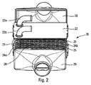
図2は、プレートの良く知られたコア21を有する良く知られた熱交換器20を描いている。なお、本発明に係るプレートは、良く知られたプレートの代わりにこのタイプの熱交換器で利用されてもよいことに留意されたい。
FIG. 2 depicts a well-known
そのような熱交換器20は、冷却されるべき流体と冷却液との間の熱の交換を可能にする。明細書本文の残りの部分では、冷却されるべき流体が空気である。このことは、本発明の範囲に何ら限定的な効果を与えず、そのため、熱交換器の他のタイプでは、冷却されるべき流体が他のガスとなり得る。
Such a
図2に示される熱交換器20は、
−冷却流体用の入口パイプ23aと、前記冷却液用の収集パイプ23bとを備える上壁22と、
−2つの側壁24a,24bと、
−1つの開放した上流側側面(見えない)および1つの開放した下流側側面26と、
−下壁と、
−下壁と上壁22との間で上下に積み重ねられたプレート25の複数の対を備えるコア21
を備える。
The
An
-Two
One open upstream side (not visible) and one open
-The lower wall;
A core 21 comprising a plurality of pairs of
Is provided.
そのようなコア21は、充填空気と、冷却流体、一般に液体との間の熱の交換を可能にする。このため、積み重ねられたプレート25は、冷却されるべき充填空気のための循環チャネルと、冷却流体のための循環チャネルとを交互に形成する。より具体的には、1つの同じ対の2つのプレート25は、冷却されるべき充填空気のための循環チャネルを形成し、また、2つの異なる隣接する対の2つのプレート25は、冷却流体のための循環チャネルを形成する。
Such a
熱交換器20のコア21のプレート25間で冷却流体を循環させるため、冷却流体のための入口チャネルおよび収集チャネルがコア21の一部に設けられる。
In order to circulate the cooling fluid between the
熱交換器20の入口パイプ23aおよび収集パイプ23bはそれぞれ、冷却流体用の循環チャネル内の冷却流体の流入および収集を可能にする。
The
冷却されるべき空気を流入させるため、冷却されるべき空気のための入口ボックス28が熱交換器20の開放した上流側側面に設置されてもよい。同様に、空気を収集するために、熱交換器20のプレート間を通過することにより冷却された後に、冷却された空気のための収集ボックス29が熱交換器20の開放した下流側側面26に設置されてもよい。
An
したがって、冷却流体は、入口パイプを介して熱交換器に入って、入口チャネル内で循環し、冷却流体用の循環チャネル内に積層されるプレートの対間で循環した後、収集チャネルを介して、その後に収集パイプを介して、熱交換器から出る。 Thus, the cooling fluid enters the heat exchanger via the inlet pipe, circulates in the inlet channel, circulates between pairs of plates stacked in the circulation channel for the cooling fluid, and then through the collection channel And then exit the heat exchanger via the collecting pipe.
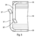
従来技術の前述した欠点の一部を排除するため、本発明は、図3に示されるように、熱交換器のためのコアのプレート30に関連する。そのようなプレート30は、ここでは、長手方向軸Xに沿って平面P内で延びるとともに、上面(31a)と、下面(見えない)と、2つの末端31b,31cと、プレート30の末端のうちの一方31bに近接する領域に設けられる冷却流体用の入口ポート32および冷却流体用の収集ポート34とを備える、長方形の長尺なパネルの形態を成して存在する。プレートはボウルの形態を成し(図3では逆さにされる)、冷却流体用の1または複数の循環チャネルを規定するために入口ポート32および収集ポート34がボウルの底部と連通する。
In order to eliminate some of the aforementioned drawbacks of the prior art, the present invention relates to a
プレート30は、冷却流体用の入口ポート32の周囲に、プレート30の平面Pに対して垂直に延びる縁部33を備える。同様に、プレート30は、冷却流体用の収集ポート34の周囲に、プレート30の平面Pに対して垂直に延びる縁部35を備える。縁部33,35は、プレート30の積層体により形成されるコアの高さに関して、冷却流体用の入口チャネルおよび収集チャネルのそれぞれをプレートの平面Pに対して垂直に形成できるようにする。
The
プレート30は、空気と冷却流体との間の熱の交換を促すことを意図する交換領域ZEと称される領域と、空気が前記交換領域ZEを迂回できるようにし得るバイパス領域ZBPと称される領域とを有する。
The
図3に示される本発明に係るプレート30では、プレートを起点に生じる手段が、交換領域ZE内で流体を強制的に循環させるように構成される。これらの手段は、ここでは、以下の形態を成す。
−ポート32の高さで、プレート30の長手方向軸に対して垂直な軸に沿って、プレート30の平面Pに対して略垂直に、プレート30の縁部から延びる長さLを有する上流側仕切り36、および、
−ポート34の高さで、プレート30の長手方向軸に対して垂直な軸に沿って、プレート30の平面Pに対して略垂直に、プレート30の縁部から延びる長さLを有する下流側仕切り37。
In the
The upstream side having a length L extending from the edge of the
The downstream side having a length L extending from the edge of the
したがって、バイパス領域ZBPは、上流側仕切り36と下流側仕切り37との間で延びる。交換領域はプレート30の残りの部分にわたって延びる。また、前記バイパス領域ZBPの高さにおける空気の通過が遮断される。
Therefore, the bypass region ZBP extends between the
本発明に係る2つのプレート30は、プレート30の対として、冷却されるべき空気流Fのための循環チャネルを形成するように、図4に示されるように上下に組み付けられてもよい。より具体的には、図3に示されるプレート30が、逆さにされるとともに、前記対を形成するように図3に示される他方の逆さにされないプレート30上に配置されてもよい。なお、プレート30の平面Pに対して垂直にポートの輪郭から延びる縁部33,35のサイズは、それらの縁部が相補的であるとともに2つのプレートが単一の対として組み付けられる際に入口チャネルおよび収集チャネルを形成するべく縁部同士が嵌合するように、1つの同じプレート対の2つのプレート間で異なってもよい。
The two
図4に示されるように、内部挿入体またはタービュレータ40が、例えば組み付け前に、プレート30の対の2つのプレート30間に挿入されてもよい。そのようなタービュレータ40は、熱の交換を向上できるようにする。
As shown in FIG. 4, an internal insert or
バイパス領域ZBPは、上流側仕切り36と、下流側仕切り37と、プレート30の対として組み付けられる2つのプレート30との間に形成される空間によっておおむね規定される。交換領域ZEは、タービュレータ40が挿入される空気の循環のための空間によって、プレート30の対として組み付けられる2つのプレート30間におおむね規定される。
The bypass region ZBP is generally defined by a space formed between the
プレート30の組み付けられた対のプレート30の長手方向軸Xに対して垂直な断面図である図5に示されるように、仕切り36,37のそれぞれの先端36’,37’は、仕切り36,37が容易に重ね合わされる、重なり合う、或いは、互いに嵌合するように構成されてもよい。
As shown in FIG. 5, which is a cross-sectional view perpendicular to the longitudinal axis X of the pair of
この目的のため、仕切り36,37は、例えば、斜めの先端縁を有してもよい。図5において、先端36’は、2つのプレート30の組み付けによって画定される空間の内部へ向けて曲げられ、また、先端37’は、2つのプレート30の組み付けによって画定される空間の外部へ向けて曲げられる。したがって、2つのプレートがプレート30の対として組み付けられるように重ね合わされる際には、先端36’,37’の対向する湾曲部が2つのプレート30の組み付けを更に容易にする。
For this purpose, the
同じ目的のため、1つの同じプレート30の仕切り36,37は、前記プレート30の長手方向軸Xに対して対称ではない。したがって、1つの同じプレート対の2つの同じプレート30が一方のプレートを他方のプレートに対して長手方向軸X周りに180°回転させた状態で互いに対向すると、一方のプレートの仕切り36は、他方のプレートの仕切り37に対して、プレート30の小さい側面の方向にオフセットされ、それにより、プレートの重ね合わせが容易になる。
For the same purpose, the
図6に示されるように、プレート30の対が熱交換器50内に設置されると、空気流Fは、冷却されるべき空気のための循環チャネルを画定するプレート30のそれぞれの対間で、上流側から下流側へ向けて、2つの異なる対のプレート30間の冷却流体循環用の各チャネル内で循環する冷却流体により冷却されるように、コア52を通過する。
As shown in FIG. 6, when a pair of
プレート30の材料から形成される仕切り36,37は、プレート30を積み重ねることによって、空気流Fを熱交換器50の上流側側面の高さで遮断できるようにする上流壁(見えない)を形成するとともに、空気流Fを熱交換器50の下流側側面の高さで遮断できるようにする下流壁54を形成する。したがって、上流壁および下流壁54は、コアのバイパス領域の高さで空気の循環を防止する。交換領域ZEは、冷却されるべき空気の循環のために開放するコアの上流部と下流部との間に画定される。
なお、図6では、明確にするため、入口パイプ23aおよび収集パイプ23bが部分的にのみ描かれ、また、熱交換器50の下壁51が見える。
In FIG. 6, for the sake of clarity, the
前述の実施形態において、交換領域ZE内で流体を強制的に循環させるように構成されるプレートを起点に生じる手段は、熱交換器50の上流面および下流面26の両方に配置される。本発明の更なる実施形態では、プレートを起点に生じる手段を例えば熱交換器50の上流面だけに配置することができる。
In the embodiment described above, the means originating from the plate configured to force the fluid to circulate in the exchange zone ZE are arranged on both the upstream and
図7に示される実施形態において、プレート70は、冷却流体のための循環チャネルを形成する入口ポート74と収集ポート76との間で延びる中央仕切りを備える。この場合のこの中央仕切りは、2つのプレート70a,70bの材料から形成されるとともに、交換領域ZEとバイパス領域ZBPとの間で空気流を遮断するようにプレート70a,70bに対して略垂直に延びる2つの隆起縁部71a,71bを備える。また、中央仕切りは、交換領域ZEとバイパス領域ZBPとの間での空気流の遮断を向上させるために、入口ポート74と収集ポート76との間に隆起縁部72a,72bを更に備える。
In the embodiment shown in FIG. 7, the plate 70 comprises a central divider that extends between an
入口ポート74と収集ポート76との間で冷却流体を案内するべく配置されるプレート70bのボウル形状形態73もこの図から理解され得る。
The bowl-shaped
プレート30およびコアの残りの部分は、有利には、金属、例えばアルミニウムおよび/またはアルミニウム合金から形成される。
The
Claims (12)
前記プレート(30)は、熱交換器(50)の他のプレート(30)と積み重ねられて、冷却されるべき流体の通過を前記プレート(30)間で許容するべく配置されるプレート(30)の対を形成するようになっており、前記プレート(30)は、流体との熱の交換を促すことを意図する交換領域(ZE)と称される領域と、流体が前記交換領域を迂回できるようにし得るバイパス領域(ZBP)と称される領域とを有し、
前記交換領域(ZE)内で流体を強制的に通過させるように構成される、前記プレート(30)を起点に生じ、前記バイパス領域(ZBP)から前記交換領域(ZE)に向かう方向に延びる手段(36,37)を更に備えることを特徴とするプレート(30)。 A plate (30) for a heat exchanger (50),
The plate (30) is stacked with the other plate (30) of the heat exchanger (50) and arranged to allow passage of the fluid to be cooled between the plates (30). The plate (30) is configured to form a pair called an exchange area (ZE) intended to facilitate the exchange of heat with the fluid and the fluid can bypass the exchange area A region called a bypass region (ZBP) that can be
Configured to forced through the fluid before Symbol exchange region (ZE), occurs starting from the said plate (30), extending in a direction toward the exchange region (ZE) from the bypass region (ZBP) Plate (30), further comprising means (36, 37).
前記プレート(30)を起点に生じる前記手段(36,37)は、前記プレート(30)の前記第1縁部から延びて前記入口ポート(32)の高さで流体の通過を遮断するように構成される第1縁部側仕切り(36)、および/または、前記プレート(30)の前記第2縁部から延びて前記収集ポート(34)の高さで流体の通過を遮断するように構成される第2縁部側仕切り(37)を備える請求項1または請求項2に記載のプレート。 The plate (30) is in the form of a panel comprising a first edge and a second edge opposite the first edge, and an inlet port (32) for cooling fluid and a collection port for the cooling fluid (34) is provided in the bypass region,
The means (36, 37) originating from the plate (30) extends from the first edge of the plate (30) and blocks the passage of fluid at the height of the inlet port (32). A first edge side partition (36) configured and / or extending from the second edge of the plate (30) and configured to block the passage of fluid at the height of the collection port (34) The plate of Claim 1 or Claim 2 provided with the 2nd edge part side partition (37) by which it is carried out.
前記長い縁部が前記第1縁部および前記第2縁部を規定し、
前記入口ポート(32)および前記収集ポート(34)が前記短い縁部のうちの一方に近接する領域で穿孔される請求項3に記載のプレート。 The plate (32) is rectangular and has two long edges and two short edges;
The long edge defines the first edge and the second edge;
The plate according to claim 3, wherein the inlet port (32) and the collection port (34) are perforated in a region proximate one of the short edges.
前記プレートは、対を形成する2つの隣接するプレート(30,70a,70b)が冷却されるべき流体のための循環チャネルを画定するとともに2つの異なる隣接する対の2つのプレート(30,70a,70b)が冷却流体のための循環チャネルを形成するように、他方の上面に一方が積み重ねられる、コア(52)。 A plate core (52) comprising a plurality of plates (30, 70a, 70b) according to any one of the preceding claims,
Said plates define a circulation channel for the fluid to be cooled, with two adjacent plates (30, 70a, 70b) forming a pair and two plates (30, 70a, A core (52), one stacked on top of the other so that 70b) forms a circulation channel for the cooling fluid.
前記タービュレータ(40)は、前記仕切り(36,37,71a,71b)の高さとほぼ同じ高さを有する請求項9または請求項10に記載のコア(52)。 Between the two plates (30, 70a, 70b) in one and the same pair of plates (30, 70), a turbulator (40 ) Is placed,
The core (52) according to claim 9 or 10, wherein the turbulator (40) has substantially the same height as the partition (36, 37, 71a, 71b).
Applications Claiming Priority (3)
| Application Number | Priority Date | Filing Date | Title |
|---|---|---|---|
| FR1102061A FR2977309B1 (en) | 2011-06-30 | 2011-06-30 | HEAT EXCHANGER BLADE WITH BYPASS AREA |
| FR1102061 | 2011-06-30 | ||
| PCT/EP2012/062585 WO2013001012A1 (en) | 2011-06-30 | 2012-06-28 | Heat exchanger plate with bypass zone |
Publications (2)
| Publication Number | Publication Date |
|---|---|
| JP2014518369A JP2014518369A (en) | 2014-07-28 |
| JP6184946B2 true JP6184946B2 (en) | 2017-08-23 |
Family
ID=46420188
Family Applications (1)
| Application Number | Title | Priority Date | Filing Date |
|---|---|---|---|
| JP2014517705A Active JP6184946B2 (en) | 2011-06-30 | 2012-06-28 | Heat exchanger plate with bypass area |
Country Status (9)
| Country | Link |
|---|---|
| US (1) | US9903661B2 (en) |
| EP (1) | EP2726805B1 (en) |
| JP (1) | JP6184946B2 (en) |
| CN (2) | CN103890525A (en) |
| ES (1) | ES2553447T3 (en) |
| FR (1) | FR2977309B1 (en) |
| MX (1) | MX338390B (en) |
| PL (1) | PL2726805T3 (en) |
| WO (1) | WO2013001012A1 (en) |
Families Citing this family (19)
| Publication number | Priority date | Publication date | Assignee | Title |
|---|---|---|---|---|
| DE102013216523A1 (en) * | 2013-08-21 | 2015-02-26 | Behr Gmbh & Co. Kg | Plate heat exchangers |
| DE102013019478B3 (en) | 2013-11-20 | 2015-01-22 | Modine Manufacturing Company | The heat exchanger assembly |
| KR101813048B1 (en) * | 2014-10-30 | 2017-12-29 | 린나이코리아 주식회사 | Plate type heat exchanger |
| KR101749059B1 (en) * | 2015-09-04 | 2017-06-20 | 주식회사 경동나비엔 | Wave plate heat exchanger |
| US9781867B2 (en) * | 2016-02-19 | 2017-10-03 | Ford Global Technologies, Llc | Power module assembly for a vehicle power inverter |
| JP6631409B2 (en) | 2016-05-23 | 2020-01-15 | 株式会社デンソー | Heat exchanger |
| US10697354B2 (en) * | 2016-08-25 | 2020-06-30 | Hanon Systems | Heat exchanger |
| CA3037066A1 (en) | 2016-10-14 | 2018-04-19 | Dana Canada Corporation | Heat exchanger having aerodynamic features to improve performance |
| JP6906130B2 (en) * | 2016-10-21 | 2021-07-21 | パナソニックIpマネジメント株式会社 | Heat exchanger and refrigeration system using it |
| JP6601384B2 (en) * | 2016-12-26 | 2019-11-06 | 株式会社デンソー | Intercooler |
| CN110199430B (en) * | 2017-01-19 | 2023-03-14 | 达纳加拿大公司 | Counterflow heat exchanger with in-line fittings |
| SI3372938T1 (en) * | 2017-03-10 | 2021-01-29 | Alfa Laval Corporate Ab | Plate package using a heat exchanger plate with integrated draining channel and a heat exchanger including such plate package |
| EP3372937B1 (en) * | 2017-03-10 | 2021-10-06 | Alfa Laval Corporate AB | Plate package for heat exchanger devices and a heat exchanger device |
| DE102017109708A1 (en) * | 2017-05-05 | 2018-11-08 | Benteler Automobiltechnik Gmbh | Cooling arrangement, fluid collector for a cooling arrangement and method for producing a fluid collector |
| EP3517873B1 (en) * | 2018-01-26 | 2021-07-21 | Modine Manufacturing Company | Heat exchanger and method of cooling a flow of heated air |
| DE202018004979U1 (en) | 2018-10-25 | 2020-01-28 | Reinz-Dichtungs-Gmbh | Plate-like liquid container and battery temperature control arrangement |
| DE102018129084A1 (en) | 2018-11-19 | 2020-05-20 | Modine Manufacturing Co. | Heat exchangers with smooth side walls |
| BE1026919B1 (en) * | 2018-12-24 | 2020-07-24 | Safran Aero Boosters Sa | AIR-OIL HEAT EXCHANGER |
| CN111029316A (en) * | 2019-12-31 | 2020-04-17 | 浙江银轮机械股份有限公司 | Chip, chip assembly, core and intercooler |
Family Cites Families (18)
| Publication number | Priority date | Publication date | Assignee | Title |
|---|---|---|---|---|
| JPS5623700A (en) * | 1979-08-03 | 1981-03-06 | Fuji Heavy Ind Ltd | Heat exchanger |
| JPS62136774U (en) * | 1986-02-14 | 1987-08-28 | ||
| DE4237672A1 (en) * | 1992-11-07 | 1994-05-11 | Mtu Friedrichshafen Gmbh | Heat-exchanger with flat tubes in stack - has inlet and outlet plenum chambers formed in stackable shaped components sealed to tube ends and connected to each other |
| CN1109232C (en) * | 1993-12-28 | 2003-05-21 | 昭和电工株式会社 | Plate heat exchanger |
| JP3965829B2 (en) * | 1999-05-25 | 2007-08-29 | 株式会社デンソー | Exhaust heat exchanger |
| US6318455B1 (en) * | 1999-07-14 | 2001-11-20 | Mitsubishi Heavy Industries, Ltd. | Heat exchanger |
| JP2002198078A (en) * | 2000-12-25 | 2002-07-12 | Calsonic Kansei Corp | Heat exchanger with catalyst for fuel cell |
| FR2855604B1 (en) * | 2003-05-28 | 2008-09-26 | Valeo Thermique Moteur Sa | PLATE HEAT EXCHANGER COMPRISING A CLOSING ELEMENT OF THE GAS LEAKS TO BE COLD. |
| DE10328638A1 (en) * | 2003-06-26 | 2005-01-20 | Modine Manufacturing Co., Racine | Heat exchanger in caseless plate design |
| JP2005055087A (en) * | 2003-08-05 | 2005-03-03 | Calsonic Kansei Corp | Laminated type heat exchanger |
| US20080041556A1 (en) * | 2006-08-18 | 2008-02-21 | Modine Manufacutring Company | Stacked/bar plate charge air cooler including inlet and outlet tanks |
| US8985198B2 (en) * | 2006-08-18 | 2015-03-24 | Modine Manufacturing Company | Stacked/bar plate charge air cooler including inlet and outlet tanks |
| FR2906017B1 (en) * | 2006-09-19 | 2012-12-21 | Valeo Systemes Thermiques | HEAT EXCHANGER, PARTICULARLY EXHAUST AIR COOLER. |
| US8678076B2 (en) * | 2007-11-16 | 2014-03-25 | Christopher R. Shore | Heat exchanger with manifold strengthening protrusion |
| SE532524C2 (en) * | 2008-06-13 | 2010-02-16 | Alfa Laval Corp Ab | Heat exchanger plate and heat exchanger assembly include four plates |
| US9239195B2 (en) * | 2011-04-26 | 2016-01-19 | Hyundai Motor Company | Heat exchanger for vehicle |
| DE102012008700A1 (en) * | 2012-04-28 | 2013-10-31 | Modine Manufacturing Co. | Heat exchanger with a radiator block and manufacturing process |
| US10962307B2 (en) * | 2013-02-27 | 2021-03-30 | Denso Corporation | Stacked heat exchanger |
-
2011
- 2011-06-30 FR FR1102061A patent/FR2977309B1/en not_active Expired - Fee Related
-
2012
- 2012-06-28 US US14/129,620 patent/US9903661B2/en active Active
- 2012-06-28 MX MX2014000208A patent/MX338390B/en active IP Right Grant
- 2012-06-28 CN CN201280032751.0A patent/CN103890525A/en active Pending
- 2012-06-28 CN CN201810310303.1A patent/CN108534572A/en active Pending
- 2012-06-28 ES ES12730956.5T patent/ES2553447T3/en active Active
- 2012-06-28 EP EP12730956.5A patent/EP2726805B1/en active Active
- 2012-06-28 PL PL12730956T patent/PL2726805T3/en unknown
- 2012-06-28 JP JP2014517705A patent/JP6184946B2/en active Active
- 2012-06-28 WO PCT/EP2012/062585 patent/WO2013001012A1/en active Application Filing
Also Published As
| Publication number | Publication date |
|---|---|
| CN103890525A (en) | 2014-06-25 |
| MX2014000208A (en) | 2014-04-25 |
| EP2726805A1 (en) | 2014-05-07 |
| US20140216700A1 (en) | 2014-08-07 |
| PL2726805T3 (en) | 2016-04-29 |
| CN108534572A (en) | 2018-09-14 |
| ES2553447T3 (en) | 2015-12-09 |
| US9903661B2 (en) | 2018-02-27 |
| JP2014518369A (en) | 2014-07-28 |
| MX338390B (en) | 2016-04-13 |
| FR2977309A1 (en) | 2013-01-04 |
| FR2977309B1 (en) | 2017-12-29 |
| WO2013001012A1 (en) | 2013-01-03 |
| EP2726805B1 (en) | 2015-08-19 |
Similar Documents
| Publication | Publication Date | Title |
|---|---|---|
| JP6184946B2 (en) | Heat exchanger plate with bypass area | |
| JP6058653B2 (en) | Especially heat exchanger for automobile | |
| US20070193732A1 (en) | Heat exchanger | |
| JP6116681B2 (en) | Heat transfer | |
| JP2018536133A (en) | Cooling system with integral core structure | |
| US20150129183A1 (en) | Heat exchanger having a cooler block and production method | |
| JP5585543B2 (en) | Vehicle cooling system | |
| US20190292979A1 (en) | Intercooler consisting of a liquid-cooled precooler and an air-cooled main cooler | |
| KR20140114770A (en) | Heat exchanger | |
| EP3561426B1 (en) | Heat exchange device | |
| US10202880B2 (en) | Exhaust heat exchanger | |
| US7774937B2 (en) | Heat exchanger with divided coolant chamber | |
| KR20140118878A (en) | Air to air heat exchanger | |
| JP2014500941A (en) | Heat exchanger and associated method of forming a flow perturbant | |
| US20150253085A1 (en) | Heat exchange for gas, particularly the exhaust gases of an engine | |
| KR20160113090A (en) | Heat exchanger for vehicle | |
| JP2009299968A (en) | Heat exchanger | |
| JP2004212041A (en) | Laminated type heat exchanger | |
| JP2009068809A (en) | Hybrid heat exchanger | |
| JP5531570B2 (en) | Boiling-cooled heat exchanger | |
| US10371465B2 (en) | Heat exchanger | |
| KR101423656B1 (en) | Exhaust gas heat exchanger | |
| JP6554182B2 (en) | Heat exchanger having a plurality of stacked plates | |
| JP2012197974A5 (en) | ||
| JP2012197974A (en) | Evaporator |
Legal Events
| Date | Code | Title | Description |
|---|---|---|---|
| A621 | Written request for application examination |
Free format text: JAPANESE INTERMEDIATE CODE: A621 Effective date: 20150626 |
|
| A977 | Report on retrieval |
Free format text: JAPANESE INTERMEDIATE CODE: A971007 Effective date: 20160622 |
|
| A131 | Notification of reasons for refusal |
Free format text: JAPANESE INTERMEDIATE CODE: A131 Effective date: 20160705 |
|
| A521 | Request for written amendment filed |
Free format text: JAPANESE INTERMEDIATE CODE: A523 Effective date: 20161005 |
|
| RD03 | Notification of appointment of power of attorney |
Free format text: JAPANESE INTERMEDIATE CODE: A7423 Effective date: 20170131 |
|
| A131 | Notification of reasons for refusal |
Free format text: JAPANESE INTERMEDIATE CODE: A131 Effective date: 20170221 |
|
| A521 | Request for written amendment filed |
Free format text: JAPANESE INTERMEDIATE CODE: A523 Effective date: 20170522 |
|
| TRDD | Decision of grant or rejection written | ||
| A01 | Written decision to grant a patent or to grant a registration (utility model) |
Free format text: JAPANESE INTERMEDIATE CODE: A01 Effective date: 20170627 |
|
| A61 | First payment of annual fees (during grant procedure) |
Free format text: JAPANESE INTERMEDIATE CODE: A61 Effective date: 20170726 |
|
| R150 | Certificate of patent or registration of utility model |
Ref document number: 6184946 Country of ref document: JP Free format text: JAPANESE INTERMEDIATE CODE: R150 |
|
| R250 | Receipt of annual fees |
Free format text: JAPANESE INTERMEDIATE CODE: R250 |
|
| R250 | Receipt of annual fees |
Free format text: JAPANESE INTERMEDIATE CODE: R250 |
|
| R250 | Receipt of annual fees |
Free format text: JAPANESE INTERMEDIATE CODE: R250 |
|
| R250 | Receipt of annual fees |
Free format text: JAPANESE INTERMEDIATE CODE: R250 |