JP6183333B2 - Hybrid car - Google Patents
Hybrid car Download PDFInfo
- Publication number
- JP6183333B2 JP6183333B2 JP2014227136A JP2014227136A JP6183333B2 JP 6183333 B2 JP6183333 B2 JP 6183333B2 JP 2014227136 A JP2014227136 A JP 2014227136A JP 2014227136 A JP2014227136 A JP 2014227136A JP 6183333 B2 JP6183333 B2 JP 6183333B2
- Authority
- JP
- Japan
- Prior art keywords
- motor
- torque
- wheel
- engine
- hybrid vehicle
- Prior art date
- Legal status (The legal status is an assumption and is not a legal conclusion. Google has not performed a legal analysis and makes no representation as to the accuracy of the status listed.)
- Expired - Fee Related
Links
Images


Classifications
-
- B—PERFORMING OPERATIONS; TRANSPORTING
- B60—VEHICLES IN GENERAL
- B60K—ARRANGEMENT OR MOUNTING OF PROPULSION UNITS OR OF TRANSMISSIONS IN VEHICLES; ARRANGEMENT OR MOUNTING OF PLURAL DIVERSE PRIME-MOVERS IN VEHICLES; AUXILIARY DRIVES FOR VEHICLES; INSTRUMENTATION OR DASHBOARDS FOR VEHICLES; ARRANGEMENTS IN CONNECTION WITH COOLING, AIR INTAKE, GAS EXHAUST OR FUEL SUPPLY OF PROPULSION UNITS IN VEHICLES
- B60K6/00—Arrangement or mounting of plural diverse prime-movers for mutual or common propulsion, e.g. hybrid propulsion systems comprising electric motors and internal combustion engines
- B60K6/20—Arrangement or mounting of plural diverse prime-movers for mutual or common propulsion, e.g. hybrid propulsion systems comprising electric motors and internal combustion engines the prime-movers consisting of electric motors and internal combustion engines, e.g. HEVs
- B60K6/42—Arrangement or mounting of plural diverse prime-movers for mutual or common propulsion, e.g. hybrid propulsion systems comprising electric motors and internal combustion engines the prime-movers consisting of electric motors and internal combustion engines, e.g. HEVs characterised by the architecture of the hybrid electric vehicle
- B60K6/44—Series-parallel type
- B60K6/445—Differential gearing distribution type
-
- B—PERFORMING OPERATIONS; TRANSPORTING
- B60—VEHICLES IN GENERAL
- B60W—CONJOINT CONTROL OF VEHICLE SUB-UNITS OF DIFFERENT TYPE OR DIFFERENT FUNCTION; CONTROL SYSTEMS SPECIALLY ADAPTED FOR HYBRID VEHICLES; ROAD VEHICLE DRIVE CONTROL SYSTEMS FOR PURPOSES NOT RELATED TO THE CONTROL OF A PARTICULAR SUB-UNIT
- B60W20/00—Control systems specially adapted for hybrid vehicles
- B60W20/10—Controlling the power contribution of each of the prime movers to meet required power demand
- B60W20/13—Controlling the power contribution of each of the prime movers to meet required power demand in order to stay within battery power input or output limits; in order to prevent overcharging or battery depletion
-
- B—PERFORMING OPERATIONS; TRANSPORTING
- B60—VEHICLES IN GENERAL
- B60K—ARRANGEMENT OR MOUNTING OF PROPULSION UNITS OR OF TRANSMISSIONS IN VEHICLES; ARRANGEMENT OR MOUNTING OF PLURAL DIVERSE PRIME-MOVERS IN VEHICLES; AUXILIARY DRIVES FOR VEHICLES; INSTRUMENTATION OR DASHBOARDS FOR VEHICLES; ARRANGEMENTS IN CONNECTION WITH COOLING, AIR INTAKE, GAS EXHAUST OR FUEL SUPPLY OF PROPULSION UNITS IN VEHICLES
- B60K28/00—Safety devices for propulsion-unit control, specially adapted for, or arranged in, vehicles, e.g. preventing fuel supply or ignition in the event of potentially dangerous conditions
- B60K28/10—Safety devices for propulsion-unit control, specially adapted for, or arranged in, vehicles, e.g. preventing fuel supply or ignition in the event of potentially dangerous conditions responsive to conditions relating to the vehicle
- B60K28/16—Safety devices for propulsion-unit control, specially adapted for, or arranged in, vehicles, e.g. preventing fuel supply or ignition in the event of potentially dangerous conditions responsive to conditions relating to the vehicle responsive to, or preventing, spinning or skidding of wheels
-
- B—PERFORMING OPERATIONS; TRANSPORTING
- B60—VEHICLES IN GENERAL
- B60K—ARRANGEMENT OR MOUNTING OF PROPULSION UNITS OR OF TRANSMISSIONS IN VEHICLES; ARRANGEMENT OR MOUNTING OF PLURAL DIVERSE PRIME-MOVERS IN VEHICLES; AUXILIARY DRIVES FOR VEHICLES; INSTRUMENTATION OR DASHBOARDS FOR VEHICLES; ARRANGEMENTS IN CONNECTION WITH COOLING, AIR INTAKE, GAS EXHAUST OR FUEL SUPPLY OF PROPULSION UNITS IN VEHICLES
- B60K6/00—Arrangement or mounting of plural diverse prime-movers for mutual or common propulsion, e.g. hybrid propulsion systems comprising electric motors and internal combustion engines
- B60K6/20—Arrangement or mounting of plural diverse prime-movers for mutual or common propulsion, e.g. hybrid propulsion systems comprising electric motors and internal combustion engines the prime-movers consisting of electric motors and internal combustion engines, e.g. HEVs
- B60K6/22—Arrangement or mounting of plural diverse prime-movers for mutual or common propulsion, e.g. hybrid propulsion systems comprising electric motors and internal combustion engines the prime-movers consisting of electric motors and internal combustion engines, e.g. HEVs characterised by apparatus, components or means specially adapted for HEVs
- B60K6/36—Arrangement or mounting of plural diverse prime-movers for mutual or common propulsion, e.g. hybrid propulsion systems comprising electric motors and internal combustion engines the prime-movers consisting of electric motors and internal combustion engines, e.g. HEVs characterised by apparatus, components or means specially adapted for HEVs characterised by the transmission gearings
- B60K6/365—Arrangement or mounting of plural diverse prime-movers for mutual or common propulsion, e.g. hybrid propulsion systems comprising electric motors and internal combustion engines the prime-movers consisting of electric motors and internal combustion engines, e.g. HEVs characterised by apparatus, components or means specially adapted for HEVs characterised by the transmission gearings with the gears having orbital motion
-
- B—PERFORMING OPERATIONS; TRANSPORTING
- B60—VEHICLES IN GENERAL
- B60K—ARRANGEMENT OR MOUNTING OF PROPULSION UNITS OR OF TRANSMISSIONS IN VEHICLES; ARRANGEMENT OR MOUNTING OF PLURAL DIVERSE PRIME-MOVERS IN VEHICLES; AUXILIARY DRIVES FOR VEHICLES; INSTRUMENTATION OR DASHBOARDS FOR VEHICLES; ARRANGEMENTS IN CONNECTION WITH COOLING, AIR INTAKE, GAS EXHAUST OR FUEL SUPPLY OF PROPULSION UNITS IN VEHICLES
- B60K6/00—Arrangement or mounting of plural diverse prime-movers for mutual or common propulsion, e.g. hybrid propulsion systems comprising electric motors and internal combustion engines
- B60K6/20—Arrangement or mounting of plural diverse prime-movers for mutual or common propulsion, e.g. hybrid propulsion systems comprising electric motors and internal combustion engines the prime-movers consisting of electric motors and internal combustion engines, e.g. HEVs
- B60K6/42—Arrangement or mounting of plural diverse prime-movers for mutual or common propulsion, e.g. hybrid propulsion systems comprising electric motors and internal combustion engines the prime-movers consisting of electric motors and internal combustion engines, e.g. HEVs characterised by the architecture of the hybrid electric vehicle
- B60K6/44—Series-parallel type
- B60K6/448—Electrical distribution type
-
- B—PERFORMING OPERATIONS; TRANSPORTING
- B60—VEHICLES IN GENERAL
- B60K—ARRANGEMENT OR MOUNTING OF PROPULSION UNITS OR OF TRANSMISSIONS IN VEHICLES; ARRANGEMENT OR MOUNTING OF PLURAL DIVERSE PRIME-MOVERS IN VEHICLES; AUXILIARY DRIVES FOR VEHICLES; INSTRUMENTATION OR DASHBOARDS FOR VEHICLES; ARRANGEMENTS IN CONNECTION WITH COOLING, AIR INTAKE, GAS EXHAUST OR FUEL SUPPLY OF PROPULSION UNITS IN VEHICLES
- B60K6/00—Arrangement or mounting of plural diverse prime-movers for mutual or common propulsion, e.g. hybrid propulsion systems comprising electric motors and internal combustion engines
- B60K6/20—Arrangement or mounting of plural diverse prime-movers for mutual or common propulsion, e.g. hybrid propulsion systems comprising electric motors and internal combustion engines the prime-movers consisting of electric motors and internal combustion engines, e.g. HEVs
- B60K6/50—Architecture of the driveline characterised by arrangement or kind of transmission units
- B60K6/52—Driving a plurality of drive axles, e.g. four-wheel drive
-
- B—PERFORMING OPERATIONS; TRANSPORTING
- B60—VEHICLES IN GENERAL
- B60W—CONJOINT CONTROL OF VEHICLE SUB-UNITS OF DIFFERENT TYPE OR DIFFERENT FUNCTION; CONTROL SYSTEMS SPECIALLY ADAPTED FOR HYBRID VEHICLES; ROAD VEHICLE DRIVE CONTROL SYSTEMS FOR PURPOSES NOT RELATED TO THE CONTROL OF A PARTICULAR SUB-UNIT
- B60W10/00—Conjoint control of vehicle sub-units of different type or different function
- B60W10/04—Conjoint control of vehicle sub-units of different type or different function including control of propulsion units
- B60W10/06—Conjoint control of vehicle sub-units of different type or different function including control of propulsion units including control of combustion engines
-
- B—PERFORMING OPERATIONS; TRANSPORTING
- B60—VEHICLES IN GENERAL
- B60W—CONJOINT CONTROL OF VEHICLE SUB-UNITS OF DIFFERENT TYPE OR DIFFERENT FUNCTION; CONTROL SYSTEMS SPECIALLY ADAPTED FOR HYBRID VEHICLES; ROAD VEHICLE DRIVE CONTROL SYSTEMS FOR PURPOSES NOT RELATED TO THE CONTROL OF A PARTICULAR SUB-UNIT
- B60W10/00—Conjoint control of vehicle sub-units of different type or different function
- B60W10/04—Conjoint control of vehicle sub-units of different type or different function including control of propulsion units
- B60W10/08—Conjoint control of vehicle sub-units of different type or different function including control of propulsion units including control of electric propulsion units, e.g. motors or generators
-
- B—PERFORMING OPERATIONS; TRANSPORTING
- B60—VEHICLES IN GENERAL
- B60W—CONJOINT CONTROL OF VEHICLE SUB-UNITS OF DIFFERENT TYPE OR DIFFERENT FUNCTION; CONTROL SYSTEMS SPECIALLY ADAPTED FOR HYBRID VEHICLES; ROAD VEHICLE DRIVE CONTROL SYSTEMS FOR PURPOSES NOT RELATED TO THE CONTROL OF A PARTICULAR SUB-UNIT
- B60W10/00—Conjoint control of vehicle sub-units of different type or different function
- B60W10/12—Conjoint control of vehicle sub-units of different type or different function including control of differentials
- B60W10/16—Axle differentials, e.g. for dividing torque between left and right wheels
-
- B—PERFORMING OPERATIONS; TRANSPORTING
- B60—VEHICLES IN GENERAL
- B60W—CONJOINT CONTROL OF VEHICLE SUB-UNITS OF DIFFERENT TYPE OR DIFFERENT FUNCTION; CONTROL SYSTEMS SPECIALLY ADAPTED FOR HYBRID VEHICLES; ROAD VEHICLE DRIVE CONTROL SYSTEMS FOR PURPOSES NOT RELATED TO THE CONTROL OF A PARTICULAR SUB-UNIT
- B60W20/00—Control systems specially adapted for hybrid vehicles
- B60W20/10—Controlling the power contribution of each of the prime movers to meet required power demand
- B60W20/15—Control strategies specially adapted for achieving a particular effect
-
- B—PERFORMING OPERATIONS; TRANSPORTING
- B60—VEHICLES IN GENERAL
- B60W—CONJOINT CONTROL OF VEHICLE SUB-UNITS OF DIFFERENT TYPE OR DIFFERENT FUNCTION; CONTROL SYSTEMS SPECIALLY ADAPTED FOR HYBRID VEHICLES; ROAD VEHICLE DRIVE CONTROL SYSTEMS FOR PURPOSES NOT RELATED TO THE CONTROL OF A PARTICULAR SUB-UNIT
- B60W2520/00—Input parameters relating to overall vehicle dynamics
- B60W2520/26—Wheel slip
-
- B—PERFORMING OPERATIONS; TRANSPORTING
- B60—VEHICLES IN GENERAL
- B60W—CONJOINT CONTROL OF VEHICLE SUB-UNITS OF DIFFERENT TYPE OR DIFFERENT FUNCTION; CONTROL SYSTEMS SPECIALLY ADAPTED FOR HYBRID VEHICLES; ROAD VEHICLE DRIVE CONTROL SYSTEMS FOR PURPOSES NOT RELATED TO THE CONTROL OF A PARTICULAR SUB-UNIT
- B60W2710/00—Output or target parameters relating to a particular sub-units
- B60W2710/06—Combustion engines, Gas turbines
-
- B—PERFORMING OPERATIONS; TRANSPORTING
- B60—VEHICLES IN GENERAL
- B60W—CONJOINT CONTROL OF VEHICLE SUB-UNITS OF DIFFERENT TYPE OR DIFFERENT FUNCTION; CONTROL SYSTEMS SPECIALLY ADAPTED FOR HYBRID VEHICLES; ROAD VEHICLE DRIVE CONTROL SYSTEMS FOR PURPOSES NOT RELATED TO THE CONTROL OF A PARTICULAR SUB-UNIT
- B60W2710/00—Output or target parameters relating to a particular sub-units
- B60W2710/08—Electric propulsion units
-
- B—PERFORMING OPERATIONS; TRANSPORTING
- B60—VEHICLES IN GENERAL
- B60W—CONJOINT CONTROL OF VEHICLE SUB-UNITS OF DIFFERENT TYPE OR DIFFERENT FUNCTION; CONTROL SYSTEMS SPECIALLY ADAPTED FOR HYBRID VEHICLES; ROAD VEHICLE DRIVE CONTROL SYSTEMS FOR PURPOSES NOT RELATED TO THE CONTROL OF A PARTICULAR SUB-UNIT
- B60W2710/00—Output or target parameters relating to a particular sub-units
- B60W2710/12—Differentials
-
- B—PERFORMING OPERATIONS; TRANSPORTING
- B60—VEHICLES IN GENERAL
- B60W—CONJOINT CONTROL OF VEHICLE SUB-UNITS OF DIFFERENT TYPE OR DIFFERENT FUNCTION; CONTROL SYSTEMS SPECIALLY ADAPTED FOR HYBRID VEHICLES; ROAD VEHICLE DRIVE CONTROL SYSTEMS FOR PURPOSES NOT RELATED TO THE CONTROL OF A PARTICULAR SUB-UNIT
- B60W2720/00—Output or target parameters relating to overall vehicle dynamics
- B60W2720/26—Wheel slip
-
- B—PERFORMING OPERATIONS; TRANSPORTING
- B60—VEHICLES IN GENERAL
- B60Y—INDEXING SCHEME RELATING TO ASPECTS CROSS-CUTTING VEHICLE TECHNOLOGY
- B60Y2200/00—Type of vehicle
- B60Y2200/90—Vehicles comprising electric prime movers
- B60Y2200/92—Hybrid vehicles
-
- Y—GENERAL TAGGING OF NEW TECHNOLOGICAL DEVELOPMENTS; GENERAL TAGGING OF CROSS-SECTIONAL TECHNOLOGIES SPANNING OVER SEVERAL SECTIONS OF THE IPC; TECHNICAL SUBJECTS COVERED BY FORMER USPC CROSS-REFERENCE ART COLLECTIONS [XRACs] AND DIGESTS
- Y02—TECHNOLOGIES OR APPLICATIONS FOR MITIGATION OR ADAPTATION AGAINST CLIMATE CHANGE
- Y02T—CLIMATE CHANGE MITIGATION TECHNOLOGIES RELATED TO TRANSPORTATION
- Y02T10/00—Road transport of goods or passengers
- Y02T10/60—Other road transportation technologies with climate change mitigation effect
- Y02T10/62—Hybrid vehicles
-
- Y—GENERAL TAGGING OF NEW TECHNOLOGICAL DEVELOPMENTS; GENERAL TAGGING OF CROSS-SECTIONAL TECHNOLOGIES SPANNING OVER SEVERAL SECTIONS OF THE IPC; TECHNICAL SUBJECTS COVERED BY FORMER USPC CROSS-REFERENCE ART COLLECTIONS [XRACs] AND DIGESTS
- Y10—TECHNICAL SUBJECTS COVERED BY FORMER USPC
- Y10S—TECHNICAL SUBJECTS COVERED BY FORMER USPC CROSS-REFERENCE ART COLLECTIONS [XRACs] AND DIGESTS
- Y10S903/00—Hybrid electric vehicles, HEVS
- Y10S903/902—Prime movers comprising electrical and internal combustion motors
- Y10S903/903—Prime movers comprising electrical and internal combustion motors having energy storing means, e.g. battery, capacitor
- Y10S903/904—Component specially adapted for hev
- Y10S903/909—Gearing
- Y10S903/91—Orbital, e.g. planetary gears
-
- Y—GENERAL TAGGING OF NEW TECHNOLOGICAL DEVELOPMENTS; GENERAL TAGGING OF CROSS-SECTIONAL TECHNOLOGIES SPANNING OVER SEVERAL SECTIONS OF THE IPC; TECHNICAL SUBJECTS COVERED BY FORMER USPC CROSS-REFERENCE ART COLLECTIONS [XRACs] AND DIGESTS
- Y10—TECHNICAL SUBJECTS COVERED BY FORMER USPC
- Y10S—TECHNICAL SUBJECTS COVERED BY FORMER USPC CROSS-REFERENCE ART COLLECTIONS [XRACs] AND DIGESTS
- Y10S903/00—Hybrid electric vehicles, HEVS
- Y10S903/902—Prime movers comprising electrical and internal combustion motors
- Y10S903/903—Prime movers comprising electrical and internal combustion motors having energy storing means, e.g. battery, capacitor
- Y10S903/93—Conjoint control of different elements
Landscapes
- Engineering & Computer Science (AREA)
- Chemical & Material Sciences (AREA)
- Combustion & Propulsion (AREA)
- Transportation (AREA)
- Mechanical Engineering (AREA)
- Automation & Control Theory (AREA)
- Hybrid Electric Vehicles (AREA)
- Control Of Vehicle Engines Or Engines For Specific Uses (AREA)
- Electric Propulsion And Braking For Vehicles (AREA)
Description
本発明は、ハイブリッド自動車に関し、詳しくは、エンジンと、動力を入出力可能な第1モータと、第1モータの回転軸とエンジンの出力軸と駆動輪に連結された駆動軸とに3つの回転要素が共線図において回転軸,出力軸,駆動軸の順に並ぶように接続されたプラネタリギヤと、駆動軸に減速ギヤを介して動力を入出力可能な第2モータと、第1モータおよび第2モータと電力をやりとり可能なバッテリと、を備えるハイブリッド自動車に関する。 The present invention relates to a hybrid vehicle. More specifically, the present invention relates to an engine, a first motor capable of inputting / outputting power, a rotation shaft of the first motor, an output shaft of the engine, and a drive shaft connected to a drive wheel. A planetary gear in which the elements are arranged in the order of the rotation axis, the output shaft, and the drive shaft in the alignment chart, a second motor capable of inputting and outputting power to the drive shaft via a reduction gear, a first motor, and a second motor The present invention relates to a hybrid vehicle including a motor and a battery capable of exchanging electric power.
従来、この種のハイブリッド自動車としては、エンジンと、第1モータと、駆動輪に連結された駆動軸とエンジンの出力軸と第1モータの回転軸とにリングギヤとキャリヤとサンギヤとが接続された動力分配統合機構(遊星歯車機構)と、駆動軸に動力を入出力可能な第2モータと、第1モータや第2モータと電力をやりとり可能なバッテリと、を備えるものが提案されている(例えば、特許文献1参照)。このハイブリッド自動車では、トラクションコントロール(TRC)がオフでモータからの動力だけで走行しているときには、スリップ速度から目標スリップ速度を減じた偏差がスリップが生じていない状態からある程度の値を超えると、偏差が大きいほど小さくなる傾向のトルクが第2モータから出力されるように第2モータを制御する。これにより、ある程度のスリップを許容するようにしている。 Conventionally, in this type of hybrid vehicle, an engine, a first motor, a drive shaft coupled to drive wheels, an output shaft of the engine, and a rotation shaft of the first motor are connected to a ring gear, a carrier, and a sun gear. A power distribution / integration mechanism (planetary gear mechanism), a second motor capable of inputting / outputting power to / from the drive shaft, and a battery capable of exchanging electric power with the first motor or the second motor have been proposed ( For example, see Patent Document 1). In this hybrid vehicle, when the traction control (TRC) is off and the vehicle is running only with the power from the motor, if the deviation obtained by subtracting the target slip speed from the slip speed exceeds a certain value from the state where no slip occurs, The second motor is controlled such that torque that tends to decrease as the deviation increases is output from the second motor. As a result, a certain amount of slip is allowed.
こうしたハイブリッド自動車において、エンジンからパワーを出力しているときに駆動輪の空転によるスリップが生じたとき、上述の制御を適用しようとすると、スリップ速度がある程度増加した後に、スリップ速度の増加に伴って走行用のトルク指令値やエンジンのパワー指令値を低下させることになる。このとき、エンジンの応答性が比較的低いために、エンジンのパワー指令値の低下に対して実際のパワーの低下が遅れ、第1モータの発電電力の低下が遅れる。この第1モータの発電電力の低下の遅れと、スリップ速度の増加(第2モータの回転数の増加)とにより、第2モータから出力してもよいトルクの許容下限が大きくなる(絶対値としては小さくなる、即ち、値0に近づく)。これは、バッテリへの入力電力が許容入力電力(入力制限)を超過しないようにするためである。こうした理由により、第2モータのトルク(パワー)を十分に低下させることができず、スリップ速度が目標スリップ速度に対してオーバーシュートすることがある。このため、スリップ速度が適切に安定しないことがある。 In such a hybrid vehicle, when slip occurs due to idling of the drive wheels while outputting power from the engine, if the above control is applied, the slip speed increases to some extent, and then increases with the slip speed. The torque command value for driving and the power command value of the engine are reduced. At this time, since the responsiveness of the engine is relatively low, the actual power decrease is delayed with respect to the decrease in the engine power command value, and the decrease in the generated power of the first motor is delayed. The allowable lower limit of the torque that may be output from the second motor is increased by the delay in the decrease in the generated power of the first motor and the increase in slip speed (increase in the rotation speed of the second motor) (as an absolute value). Becomes smaller, ie, approaches the value 0). This is to prevent the input power to the battery from exceeding the allowable input power (input limit). For these reasons, the torque (power) of the second motor cannot be sufficiently reduced, and the slip speed may overshoot the target slip speed. For this reason, the slip speed may not be properly stabilized.
本発明のハイブリッド自動車は、スリップ速度をより適切に安定させることを主目的とする。 The main purpose of the hybrid vehicle of the present invention is to stabilize the slip speed more appropriately.
本発明のハイブリッド自動車は、上述の主目的を達成するために以下の手段を採った。 The hybrid vehicle of the present invention employs the following means in order to achieve the main object described above.
本発明のハイブリッド自動車は、
エンジンと、動力を入出力可能な第1モータと、前記第1モータの回転軸と前記エンジンの出力軸と駆動輪に連結された駆動軸とに3つの回転要素が共線図において前記回転軸,前記出力軸,前記駆動軸の順に並ぶように接続されたプラネタリギヤと、前記駆動軸に動力を入出力可能な第2モータと、前記第1モータおよび前記第2モータと電力をやりとり可能なバッテリと、前記バッテリの許容入出力電力の範囲内で走行するように前記エンジンと前記第1モータと前記第2モータとを制御する制御手段と、を備えるハイブリッド自動車であって、
前記制御手段は、前記駆動輪の空転によるスリップが生じたときには、前記駆動輪と路面との間の動摩擦力と釣り合う釣合駆動力に基づいて上限駆動力を設定し、該上限駆動力以下の駆動力が前記駆動輪に出力されるように前記エンジンと前記第1モータと前記第2モータとを制御する手段である、
ことを特徴とする。
The hybrid vehicle of the present invention
An engine, a first motor capable of inputting / outputting power, a rotation shaft of the first motor, an output shaft of the engine, and a drive shaft connected to a drive wheel have three rotation elements in the collinear diagram. , The planetary gear connected in order of the output shaft and the drive shaft, a second motor capable of inputting and outputting power to the drive shaft, and a battery capable of exchanging power with the first motor and the second motor And a control means for controlling the engine, the first motor, and the second motor so as to run within a range of allowable input / output power of the battery,
The control means sets an upper limit driving force based on a balance driving force that balances a dynamic frictional force between the driving wheel and a road surface when slippage due to idling of the driving wheel occurs, and the control means Means for controlling the engine, the first motor, and the second motor such that a driving force is output to the driving wheel;
It is characterized by that.
この本発明のハイブリッド自動車では、駆動輪の空転によるスリップが生じたときには、駆動輪と路面との間の動摩擦力と釣り合う釣合駆動力に基づいて上限駆動力を設定し、上限駆動力以下の駆動力が駆動輪に出力されるようにエンジンと第1モータと第2モータとを制御する。このように、駆動輪の空転によるスリップが生じたときに、駆動輪に出力する駆動力をこの上限駆動力に迅速に(スリップ速度がある程度増加する前に)制限することにより、第2モータのトルクを十分に小さくすることができる。そして、釣合駆動力に基づく上限駆動力を用いることにより、駆動輪のスリップ速度をより適切に安定させることができる。 In the hybrid vehicle of the present invention, when slippage due to idling of the drive wheels occurs, the upper limit drive force is set based on the balance drive force that balances the dynamic frictional force between the drive wheel and the road surface, The engine, the first motor, and the second motor are controlled so that the driving force is output to the driving wheels. As described above, when slipping due to idling of the driving wheel occurs, the driving force output to the driving wheel is quickly limited to the upper limit driving force (before the slip speed increases to some extent), thereby Torque can be made sufficiently small. And the slip speed of a driving wheel can be stabilized more appropriately by using the upper limit driving force based on the balance driving force.
こうした本発明のハイブリッド自動車において、前記制御手段は、前記駆動輪の空転によるスリップが生じたときには、前記釣合駆動力と、前記駆動輪の目標スリップ速度と現在のスリップ速度との差分であるスリップ差分が打ち消されるようにするための補正駆動力と、の和を前記上限駆動力に設定する手段である、ものとすることもできる。こうすれば、駆動輪のスリップ速度を目標スリップ速度に近づけて安定させることができる。 In such a hybrid vehicle of the present invention, when the slip due to idling of the drive wheel occurs, the control means is a slip that is a difference between the balance drive force, the target slip speed of the drive wheel, and the current slip speed. The sum of the correction driving force for canceling out the difference and the upper limit driving force may be set as the upper limit driving force. If it carries out like this, the slip speed of a driving wheel can be brought close to the target slip speed, and can be stabilized.
また、本発明のハイブリッド自動車において、前記制御手段は、少なくとも前記許容入出力電力の絶対値が所定値以下のときに、前記駆動輪の空転によるスリップが生じたときには、前記上限駆動力以下の駆動力が前記駆動輪に出力されるように制御する手段である、ものとすることもできる。 In the hybrid vehicle of the present invention, the control means drives at or below the upper limit driving force when slipping occurs due to idling of the driving wheels when at least the absolute value of the allowable input / output power is at or below a predetermined value. It can also be a means for controlling the force to be output to the drive wheel.
さらに、本発明のハイブリッド自動車において、前記駆動輪とは異なる第2駆動輪に連結された第2駆動軸に動力を入出力可能であると共に前記バッテリと電力をやりとり可能な第3モータを更に備え、前記制御手段は、前記バッテリの最大許容入出力電力の範囲内で走行するように前記エンジンと前記第1モータと前記第2モータと前記第3モータとを制御する手段であり、更に、前記制御手段は、前記第2駆動輪の空転によるスリップが生じたときには、前記第2駆動輪と路面との間の動摩擦力と釣り合う第2釣合駆動力に基づいて第2上限駆動力を設定し、該第2上限駆動力以下の駆動力が前記第2駆動輪に出力されるように前記第3モータを制御する手段である、ものとすることもできる。このように、第2釣合駆動力に基づく第2上限駆動力を用いて第3モータを制御することにより、第2駆動輪のスリップ速度をより適切に安定させることができる。 Furthermore, the hybrid vehicle of the present invention further includes a third motor capable of inputting / outputting power to / from a second drive shaft connected to a second drive wheel different from the drive wheel and exchanging electric power with the battery. The control means is means for controlling the engine, the first motor, the second motor, and the third motor so as to run within a range of maximum allowable input / output power of the battery, and The control means sets a second upper limit driving force based on a second balanced driving force that balances a dynamic frictional force between the second driving wheel and the road surface when slippage occurs due to idling of the second driving wheel. The third motor may be a means for controlling the third motor so that a driving force equal to or less than the second upper limit driving force is output to the second driving wheel. Thus, the slip speed of the second drive wheel can be more appropriately stabilized by controlling the third motor using the second upper limit drive force based on the second balance drive force.
第3モータを備える態様の本発明のハイブリッド自動車において、前記制御手段は、前記第2駆動輪の空転によるスリップが生じたときには、前記第2釣合駆動力と、前記第2駆動輪の目標スリップ速度と現在のスリップ速度との差分である第2スリップ差分が打ち消されるようにするための第2補正駆動力と、の和を前記第2上限駆動力に設定する手段である、ものとすることもできる。こうすれば、第2駆動輪のスリップ速度を目標スリップ速度に近づけて安定させることができる。 In the hybrid vehicle of the present invention having a third motor, the control means may be configured such that when slippage occurs due to idling of the second drive wheel, the second balance drive force and a target slip of the second drive wheel. It is a means for setting the sum of the second correction driving force for canceling out the second slip difference, which is the difference between the speed and the current slip speed, to the second upper limit driving force. You can also. In this way, the slip speed of the second drive wheel can be stabilized close to the target slip speed.
第3モータを備える態様の本発明のハイブリッド自動車において、前記制御手段は、少なくとも前記許容入出力電力の絶対値が所定値以下のときに、前記駆動輪の空転によるスリップが生じたときには、前記上限駆動力以下の駆動力が前記駆動輪に出力されるように制御する手段である、ものとすることもできる。 In the hybrid vehicle according to the aspect of the invention including the third motor, the control unit may be configured such that when the absolute value of the allowable input / output power is equal to or less than a predetermined value and slip occurs due to idling of the drive wheel, the upper limit It may be a means for controlling so that a driving force equal to or less than the driving force is output to the driving wheel.
第3モータを備える態様の本発明のハイブリッド自動車において、前記制御手段は、前記駆動輪と前記第2駆動輪とのいずれか一方または両方に空転によるスリップが生じたときには、前記駆動輪のトルクと前記第2駆動輪のトルクの分配比が許容範囲内となるように制御する手段である、ものとすることもできる。こうすれば、駆動輪のトルクと第2駆動輪のトルクとの分配比が許容範囲から外れるのを抑制することができる。ここで、「許容分配比範囲」は、走行性能を十分に確保可能な分配比の範囲である、ものとすることもできる。 In the hybrid vehicle according to the aspect of the invention including the third motor, the control unit may calculate the torque of the driving wheel when slipping due to idling occurs in one or both of the driving wheel and the second driving wheel. It may be a means for controlling the distribution ratio of the torque of the second driving wheel to be within an allowable range. By so doing, it is possible to prevent the distribution ratio between the torque of the drive wheels and the torque of the second drive wheels from deviating from the allowable range. Here, the “allowable distribution ratio range” may be a distribution ratio range that can sufficiently ensure traveling performance.
次に、本発明を実施するための形態を実施例を用いて説明する。 Next, the form for implementing this invention is demonstrated using an Example.
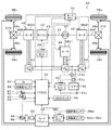
図1は、本発明の一実施例としてのハイブリッド自動車20の構成の概略を示す構成図である。実施例のハイブリッド自動車20は、図示するように、エンジン22と、プラネタリギヤ30と、モータMG1,MG2,MG3と、インバータ41,42,43と、バッテリ50と、ブレーキアクチュエータ94と、ハイブリッド用電子制御ユニット(以下、HVECUという)70と、を備える。
FIG. 1 is a configuration diagram showing an outline of the configuration of a
エンジン22は、ガソリンや軽油などを燃料として動力を出力する内燃機関として構成されている。このエンジン22は、エンジン用電子制御ユニット(以下、エンジンECUという)24により運転制御されている。
The
エンジンECU24は、図示しないが、CPUを中心とするマイクロプロセッサとして構成されており、CPUの他に、処理プログラムを記憶するROMやデータを一時的に記憶するRAM,入出力ポート,通信ポートを備える。エンジンECU24には、エンジン22を運転制御するのに必要な各種センサからの信号、例えば、クランクシャフト26の回転位置を検出するクランクポジションセンサ23からのクランク角θcrなどが入力ポートを介して入力されている。また、エンジンECU24からは、エンジン22を運転制御するための種々の制御信号、例えば、燃料噴射弁への駆動信号,スロットルバルブのポジションを調節するスロットルモータへの駆動信号,イグナイタと一体化されたイグニッションコイルへの制御信号などが出力ポートを介して出力されている。エンジンECU24は、クランクポジションセンサ23により検出されたクランク角θcrに基づいてクランクシャフト26の回転数、即ち、エンジン22の回転数Neを演算している。エンジンECU24は、HVECU70と通信ポートを介して接続されており、HVECU70からの制御信号によりエンジン22を運転制御すると共に必要に応じてエンジン22の運転状態に関するデータをHVECU70に出力する。
Although not shown, the engine ECU 24 is configured as a microprocessor centered on a CPU, and includes a ROM for storing a processing program, a RAM for temporarily storing data, an input / output port, and a communication port in addition to the CPU. . The engine ECU 24 receives signals from various sensors necessary for controlling the operation of the
プラネタリギヤ30は、シングルピニオン式の遊星歯車機構として構成されている。プラネタリギヤ30のサンギヤには、モータMG1の回転子が接続されている。プラネタリギヤ30のリングギヤには、前輪38a,38bにデファレンシャルギヤ37Fを介して連結された駆動軸36Fが接続されている。プラネタリギヤ30のキャリヤには、エンジン22のクランクシャフト26が接続されている。
The
モータMG1は、例えば同期発電電動機として構成されており、上述したように回転子がプラネタリギヤ30のサンギヤに接続されている。モータMG2は、例えば同期発電電動機として構成されており、回転子が駆動軸36Fに接続されている。モータMG3は、例えば同期発電電動機として構成されており、後輪38c,38dにデファレンシャルギヤ37Rを介して連結された駆動軸36Rが接続されている。モータMG1,MG2,MG3は、モータ用電子制御ユニット(以下、モータECUという)40によってインバータ41,42,43の図示しないスイッチング素子がスイッチング制御されることにより、回転駆動される。
The motor MG1 is configured as a synchronous generator motor, for example, and the rotor is connected to the sun gear of the
モータECU40は、図示しないが、CPUを中心とするマイクロプロセッサとして構成されており、CPUの他に、処理プログラムを記憶するROMやデータを一時的に記憶するRAM,入出力ポート,通信ポートを備える。モータECU40には、モータMG1,MG2,MG3を駆動制御するのに必要な各種センサからの信号、例えば、モータMG1,MG2,MG3の回転子の回転位置を検出する回転位置検出センサ44,45,46からの回転位置θm1,θm2,θm3,モータMG1,MG2,MG3の各相に流れる電流を検出する電流センサからの相電流などが入力ポートを介して入力されている。モータECU40からは、インバータ41,42,43の図示しないスイッチング素子へのスイッチング制御信号などが出力ポートを介して出力されている。モータECU40は、回転位置検出センサ44,45,46により検出されたモータMG1,MG2,MG3の回転子の回転位置θm1,θm2,θm3に基づいてモータMG1,MG2,MG3の回転数Nm1,Nm2,Nm3を演算している。モータECU40は、HVECU70と通信ポートを介して接続されており、HVECU70からの制御信号によってモータMG1,MG2,MG3を駆動制御すると共に必要に応じてモータMG1,MG2,MG3の駆動状態に関するデータをHVECU70に出力する。
Although not shown, the
バッテリ50は、例えばリチウムイオン二次電池やニッケル水素二次電池として構成されており、インバータ41,42,43を介してモータMG1,MG2,MG3と電力をやりとりする。このバッテリ50は、バッテリ用電子制御ユニット(以下、バッテリECUという)52により管理されている。
The
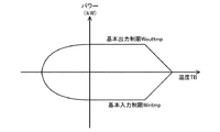
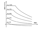
バッテリECU52は、図示しないが、CPUを中心とするマイクロプロセッサとして構成されており、CPUの他に、処理プログラムを記憶するROMやデータを一時的に記憶するRAM,入出力ポート,通信ポートを備える。バッテリECU52には、バッテリ50を管理するのに必要な信号、例えば、バッテリ50の端子間に設置された電圧センサ51aからの電池電圧VB,バッテリ50の出力端子に取り付けられた電流センサ51bからの電池電流IB,バッテリ50に取り付けられた温度センサ51cからの電池温度TBなどが入力ポートを介して入力されている。バッテリECU52は、バッテリ50を管理するために、電流センサ51bにより検出された電池電流IBの積算値に基づいてそのときのバッテリ50から放電可能な電力の容量の全容量に対する割合である蓄電割合SOCを演算したり、演算した蓄電割合SOCと温度センサ51cにより検出された電池温度TBとに基づいてバッテリ50を充放電してもよい許容入出力電力である入出力制限Win,Woutを演算したりしている。バッテリ50の入出力制限Win,Woutは、電池温度TBに基づいて入出力制限Win,Woutの基本値である基本入出力制限Wintmp,Wouttmpを設定し、バッテリ50の蓄電割合SOCに基づいて入出力制限用補正係数kin,koutを設定し、基本入出力制限Wintmp,Wouttmpに入出力制限用補正係数kin,koutを乗じることにより、設定することができる。図2に、バッテリ50の電池温度Tbと基本入出力制限Wintmp,Wouttmpとの関係の一例を示し、図3に、バッテリ50の蓄電割合SOCと入出力制限用補正係数kin,koutとの関係の一例を示す。バッテリECU52は、HVECU70と通信ポートを介して接続されており、必要に応じてバッテリ50の状態に関するデータをHVECU70に出力する。
Although not shown, the
ブレーキアクチュエータ94は、前輪38a,38bや後輪38c,38dに制動力を付与するためのアクチュエータとして構成されている。具体的には、ブレーキアクチュエータ94は、ブレーキペダル85の踏み込みに応じて生じるマスタシリンダ92の圧力(ブレーキ圧)と車体速Vcとに応じて車両に作用させる制動力を設定して、その制動力のうちブレーキの分担分に応じた制動力が前輪38a,38bや後輪38c,38dに作用するようにブレーキホイールシリンダ96a,96b,96c,96dの油圧を調整したり、ブレーキペダル85の踏み込みとは無関係に、制動力が前輪38a,38bや後輪38c,38dに作用するようにブレーキホイールシリンダ96a,96b,96c,96dへの油圧を調整したりすることができるように構成されている。このブレーキアクチュエータ94は、ブレーキ用電子制御ユニット(以下、ブレーキECUという)98により駆動制御されている。
The
ブレーキECU98は、図示しないが、CPUを中心とするマイクロプロセッサとして構成されており、CPUの他に、処理プログラムを記憶するROMやデータを一時的に記憶するRAM,入出力ポート,通信ポートを備える。ブレーキECU98には、ブレーキアクチュエータ94を駆動制御するのに必要な各種センサからの信号、例えば、マスタシリンダ92に取り付けられた図示しない圧力センサにより検出されるマスタシリンダ圧(ブレーキ踏力Fb),前輪38a,38bや後輪38c,38dに取り付けられた車輪速センサ99a〜99dからの車輪速Vwa〜Vwd,操舵角センサ99stからの操舵角θstなどが入力ポートを介して入力されている。ブレーキECU98からは、ブレーキアクチュエータ94への駆動制御信号などが出力ポートを介して出力されている。ブレーキECU94は、HVECU70と通信ポートを介して接続されており、HVECU70からの制御信号によってブレーキアクチュエータ92を駆動制御したり、必要に応じてブレーキアクチュエータ92の状態に関するデータをHVECU70に出力する。ブレーキECU98は、車輪速センサ99a〜99dからの前輪38a,38bや後輪38c,38dの車輪速Vwa〜Vwdや操舵角センサ99stからの操舵角θstなどの信号を入力し、運転者がブレーキペダル85を踏み込んだときに前輪38a,38bや後輪38c,38dのいずれかがロックによりスリップするのを防止するアンチロックブレーキ装置機能(ABS)や運転者がアクセルペダル83を踏み込んだときに前輪38a,38bのいずれかが空転によりスリップするのを防止するトラクションコントロール(TRC),車両が旋回走行しているときに姿勢を保持する姿勢保持制御(VSC)などの車両挙動安定制御を行なう。
Although not shown, the
HVECU70は、図示しないが、CPUを中心とするマイクロプロセッサとして構成されており、CPUの他に、処理プログラムを記憶するROMやデータを一時的に記憶するRAM,入出力ポート,通信ポートを備える。HVECU70には、イグニッションスイッチ80からのイグニッション信号,シフトレバー81の操作位置を検出するシフトポジションセンサ82からのシフトポジションSP,アクセルペダル83の踏み込み量を検出するアクセルペダルポジションセンサ84からのアクセル開度Acc,ブレーキペダル85の踏み込み量を検出するブレーキペダルポジションセンサ86からのブレーキペダルポジションBP,加速度センサ88からの車体加速度αc,姿勢保持制御オフスイッチ(以下、VSCオフスイッチという)89からのスイッチ信号などが入力ポートを介して入力されている。HVECU70は、加速度センサ88により検出された車体加速度αcの積算値に基づいて車体速Vcを演算している。HVECU70は、上述したように、エンジンECU24やモータECU40,バッテリECU52と通信ポートを介して接続されており、エンジンECU24やモータECU40,バッテリECU52と各種制御信号やデータのやりとりを行なっている。
Although not shown, the
こうして構成された実施例のハイブリッド自動車20は、エンジン22の運転を伴って走行するハイブリッド走行モード(HV走行モード)やエンジン22の運転を停止して走行する電動走行モード(EV走行モード)で走行する。
The
次に、こうして構成された実施例のハイブリッド自動車20の動作、特に、低温時などバッテリ50の入出力制限Win,Woutの絶対値が十分に小さく且つVSCオフスイッチ89がオンである(姿勢保持制御(VSC)を行なわない)ときの動作について説明する。図4および図5は、実施例のHVECU70により実行されるVSCオフ時駆動制御ルーチンの一例を示すフローチャートである。このルーチンは、バッテリ50の入出力制限Win,Woutの絶対値が閾値Wref(例えば2kWや3kWなど)以下で且つVSCオフスイッチ89がオフのときに、所定時間毎(例えば、数msec毎)に繰り返し実行される。
Next, the operation of the
VSCオフ時駆動制御ルーチンが実行されると、HVECU70は、まず、アクセルペダルポジションセンサ84からのアクセル開度Acc,加速度センサ88からの車体加速度αc,車体速Vc,モータMG1,MG2,MG3の回転数Nm1,Nm2,Nm3,バッテリ50の入出力制限Win,Wout,操舵角θst,前輪スリップ速度Vsf,後輪スリップ速度Vsrなどのデータを入力する(ステップS100)。
When the VSC off-time drive control routine is executed, the
ここで、車体速Vcは、加速度センサ88により検出された車体加速度αcに基づいて演算された値を入力するものとした。モータMG1,MG2,MG3の回転数Nm1,Nm2,Nm3は、回転位置検出センサ44,45,46により検出されたモータMG1,MG2,MG3の回転子の回転位置θm1,θm2,θm3に基づいて演算された値をモータECU40から通信により入力するものとした。バッテリ50の入出力制限Win,Woutは、温度センサ51cにより検出された電池温度TBと、電流センサ51bにより検出された電池電流IBの積算値に基づくバッテリ50の蓄電割合SOCと、に基づいて設定された値をバッテリECU52から通信により入力するものとした。操舵角θstは、操舵角センサ99stにより検出された値をブレーキECU98から通信により入力するものとした。前輪スリップ速度Vsfは、前輪38a,38bの車輪速Vwa,Vwbの平均値Vwfを車体速に換算した値Vcfから車体速Vcを減じた値を入力するものとした。後輪スリップ速度Vsrは、後輪38c,38dの車輪速Vwc,Vwdの平均値Vwrを車体速に換算した値Vcrから車体速Vcを減じた値を入力するものとした。なお、前輪38a,38bや後輪38c,38dの車輪速Vwa〜Vwdは、車輪速センサ99a〜99dにより検出された値をブレーキECU98から通信により入力するものとした。
Here, as the vehicle body speed Vc, a value calculated based on the vehicle body acceleration αc detected by the
こうしてデータを入力すると、入力したアクセル開度Accと車体速Vcとに基づいて、走行に要求される要求トルクTd*を設定する(ステップS110)。ここで、要求トルクTd*は、実施例では、アクセル開度Accと車体速Vcと要求トルクTd*との関係を予め定めて要求トルク設定用マップとして図示しないROMに記憶しておき、アクセル開度Accと車体速Vcとが与えられると記憶したマップから対応する要求トルクTd*を導出して設定するものとした。要求トルク設定用マップの一例を図6に示す。 When the data is input in this way, the required torque Td * required for traveling is set based on the input accelerator opening Acc and the vehicle speed Vc (step S110). Here, the required torque Td * is stored in a ROM (not shown) as a required torque setting map by predetermining the relationship among the accelerator opening Acc, the vehicle speed Vc, and the required torque Td * in the embodiment. When the degree Acc and the vehicle body speed Vc are given, the corresponding required torque Td * is derived from the stored map and set. An example of the required torque setting map is shown in FIG.
続いて、車体加速度αcや操舵角θstに基づいて、前輪要求分配比Df*および後輪要求分配比Dr*を設定する(ステップS120)。ここで、前輪要求分配比Df*,後輪要求分配比Dr*は、それぞれ、前輪38a,38bのトルクと後輪38c,38dのトルクとの和に対する前輪38a,38b,後輪38c,38dのトルクの割合(以下、前輪,後輪分配比という)Df,Drの要求値である。前輪要求分配比Df*と後輪要求分配比Dr*との和は値1となる。前輪要求分配比Df*および後輪要求分配比Dr*は、実施例では、後輪要求分配比Dr*が最大後輪分配比Drmax以下となる範囲内で、車体加速度αcが大きいほど後輪要求分配比Dr*が大きくなる(前輪要求分配比Df*が小さくなる)傾向で、且つ、操舵角θstの絶対値が大きいほど後輪要求分配比Dr*が大きくなる(前輪要求分配比Df*が小さくなる)傾向に設定するものとした。こうした傾向に前輪要求分配比Df*および後輪要求分配比Dr*を設定するのは、加速時や旋回時の走行性能を向上させるためである。また、最大後輪分配比Drmaxは、走行性能を十分に確保可能な後輪分配比Dr*の上限であり、車両の質量Mに対して停車時に前輪38a,38b,後輪38c,38dに作用する質量の割合である前輪静荷重分配比Kwsf,後輪静荷重分配比Kwsrなどに基づいて定めることができ、例えば、0.55や0.60,0.65などを用いることができる。
Subsequently, the front wheel required distribution ratio Df * and the rear wheel required distribution ratio Dr * are set based on the vehicle body acceleration αc and the steering angle θst (step S120). Here, the front wheel required distribution ratio Df * and the rear wheel required distribution ratio Dr * are respectively the
こうして前輪要求分配比Df*および後輪要求分配比Dr*を設定すると、要求トルクTd*に前輪要求分配比Df*を乗じて、前輪38a,38bに要求される前輪要求トルクTf*を計算すると共に要求トルクTd*に後輪要求分配比Dr*を乗じて、後輪38c,38dに要求される後輪要求トルクTr*を計算する(ステップS130)。
When the front wheel required distribution ratio Df * and the rear wheel required distribution ratio Dr * are thus set, the front wheel required torque Tf * required for the
次に、前輪38a,38bと後輪38c,38dとのいずれか一方または両方が空転によりスリップしているか否かを判定する(ステップS140)。ここで、前輪38a,38bが空転によりスリップしているか否かの判定は、前輪スリップ速度Vsfと閾値Vsfrefとの比較により行なうものとした。閾値Vsfrefは、例えば、1km/hや2km/h,3km/hなどを用いることができる。また、後輪38c,38dが空転によりスリップしているか否かの判定は、後輪スリップ速度Vsrと閾値Vsrrefとの比較により行なうものとした。閾値Vsrrefは、例えば、1km/hや2km/h,3km/hなどを用いることができる。
Next, it is determined whether any one or both of the
ステップS140で前輪38a,38bも後輪38c,38dも空転によりスリップしていないと判定されたときには、次式(1)に示すように、前輪要求トルクTf*にモータMG2の回転数Nm2(駆動軸36Fの回転数)を乗じた値(Tf*・Nm2)と、後輪要求トルクTr*にモータMG3の回転数Nm3(駆動軸36Rの回転数)を乗じた値(Tr*・Nm3)と、の和からバッテリ50の充放電要求パワーPb*(バッテリ50から放電するときが正の値)を減じて、エンジン22に要求される要求パワーPe*を計算する(ステップS270)。ここで、値(Tf*・Nm2)は、前輪38a,38bに要求されるパワーを意味し、値(Tr*・Nm3)は、後輪38c,38dに要求されるパワーを意味する。
When it is determined in step S140 that neither the
Pe*=Tf*・Nm2+Tr*・Nm3-Pb* (1) Pe * = Tf * ・ Nm2 + Tr * ・ Nm3-Pb * (1)
こうしてエンジン22の要求パワーPe*を計算すると、計算した要求パワーPe*と、エンジン22を効率よく運転するための動作ラインと、に基づいてエンジン22の目標回転数Ne*および目標トルクTe*を設定する(ステップS280)。図7は、エンジン22の動作ラインの一例と目標回転数Ne*および目標トルクTe*を設定する様子とを示す説明図である。エンジン22の目標回転数Ne*および目標トルクTe*は、図示するように、エンジン22の動作ラインと要求パワーPe*が一定の曲線(要求パワーPe*の等パワーライン)との交点として求めることができる。
When the required power Pe * of the
こうしてエンジン22の目標トルクTe*を設定すると、エンジン22の目標トルクTe*に応答遅れ補償(むだ時間補償や一次遅れ補償)を施して、エンジン22のトルクTeの推定値としての推定出力トルクTeestを設定する(ステップS290)。ここで、エンジン22の目標トルクTe*に対する応答遅れ補償は、エンジン22からのトルクの目標トルクTe*に対する応答遅れ(むだ時間や一次遅れ)の程度として予め実験や解析などによって定めた値を用いて目標トルクTe*に施す補償である。
When the target torque Te * of the
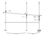
次に、エンジン22の目標回転数Ne*とモータMG2の回転数Nm2(駆動軸36Fの回転数)とプラネタリギヤ30のギヤ比ρとを用いて次式(2)によりモータMG1の目標回転数Nm1*を計算し、計算した目標回転数Nm1*とモータMG1の現在の回転数Nm1とエンジン22の目標トルクTe*とプラネタリギヤ30のギヤ比ρとを用いて式(2)によりモータMG1のトルク指令Tm1*の仮の値としての仮トルクTm1tmpを計算する(ステップS300)。ここで、式(2)は、プラネタリギヤ30の回転要素に対する力学的な関係式である。図8は、HV走行モードで走行する際のプラネタリギヤ30の回転要素における回転数とトルクとの力学的な関係を示す共線図の一例を示す説明図である。図中、左のS軸はモータMG1の回転数Nm1であるサンギヤの回転数を示し、C軸はエンジン22の回転数Neであるキャリヤの回転数を示し、R軸はモータMG2の回転数Nm2であるリングギヤ(駆動軸36F)の回転数を示す。また、図中、R軸上の2つの太線矢印は、モータMG1から出力されてプラネタリギヤ30を介して駆動軸36Fに作用するトルクと、モータMG2から出力されて駆動軸36Fに作用するトルクと、を示す。式(2)は、この共線図を用いれば容易に導くことができる。また、式(3)は、モータMG1を目標回転数Nm1*で回転させる(エンジン22を目標回転数Ne*で回転させる)ためのフィードバック制御における関係式である。式(3)中、右辺第1項はフィードフォワード項であり、右辺第2項,第3項はフィードバック項の比例項,積分項である。また、式(3)中、右辺第2項の「kpn」は比例項のゲインであり、右辺第3項の「kin」は積分項のゲインである。
Next, using the target rotational speed Ne * of the
Nm1*=Ne*・(1+ρ)/ρ-Nm2/ρ (2)
Tm1tmp=-ρ・Te*/(1+ρ)+kpn・(Nm1*-Nm1)+kin・∫(Nm1*-Nm1)dt (3)
Nm1 * = Ne * ・ (1 + ρ) / ρ-Nm2 / ρ (2)
Tm1tmp = -ρ ・ Te * / (1 + ρ) + kpn ・ (Nm1 * -Nm1) + kin ・ ∫ (Nm1 * -Nm1) dt (3)
続いて、次式(4)に示すように、モータMG1の仮トルクTm1tmpをプラネタリギヤ30のギヤ比ρで除した値を前輪要求トルクTf*に加えて、モータMG2のトルク指令Tm2*の仮の値としての仮トルクTm2tmpを計算する(ステップS310)。そして、後輪要求トルクTr*をモータMG3のトルク指令Tm3*の仮の値としての仮トルクTm3tmpに設定する(ステップS320)。ここで、式(4)は、図6の共線図を用いれば容易に導くことができる。
Subsequently, as shown in the following formula (4), a value obtained by dividing the temporary torque Tm1tmp of the motor MG1 by the gear ratio ρ of the
Tm2tmp=Tf*+Tm1tmp/ρ (4) Tm2tmp = Tf * + Tm1tmp / ρ (4)
こうしてモータMG1,MG2,MG3の仮トルクTm1tmp,Tm2tmp,Tm3tmpを設定すると、モータMG1,MG2,MG3の総消費電力Pmがバッテリ50の入出力制限Win,Woutの範囲内となる電力条件と、前輪38a,38bのトルク(−Tm1*/ρ+Tm2*)と後輪38c,38dのトルク(Tm3*)とについての前輪,後輪分配比が前輪,後輪要求分配比Df*,Dr*となる分配比条件とを満たすように、モータMG1,MG2,MG3の仮トルクTm1tmp,Tm2tmp,Tm3tmpを制限して(必要に応じて補正して)、トルク指令Tm1*,Tm2*,Tm3*を設定する(ステップS330)。
When the temporary torques Tm1tmp, Tm2tmp, and Tm3tmp of the motors MG1, MG2, and MG3 are set in this way, the power condition that the total power consumption Pm of the motors MG1, MG2, and MG3 is within the range of the input / output limits Win and Wout of the
ここで、モータMG1,MG2,MG3の総消費電力Pmは、モータMG1,MG2,MG3の消費電力Pm1,Pm2,Pm3の和として計算するものとした。モータMG1の消費電力Pm1は、モータMG1のトルク指令Tm1*と回転数Nm1との積として計算するものとした。モータMG2の消費電力Pm2は、モータMG2のトルク指令Tm2*と回転数Nm2との積として計算するものとした。モータMG3の消費電力Pm3は、モータMG3のトルク指令Tm3*と回転数Nm3との積として計算するものとした。なお、図8から分かるように、モータMG1は、エンジン22の回転数を押さえ込む方向のトルクを出力する。このため、モータMG1の回転数Nm1が正の場合、モータMG1の消費電力Pm1は負の値(発電側の値)となる。
Here, the total power consumption Pm of the motors MG1, MG2, and MG3 is calculated as the sum of the power consumptions Pm1, Pm2, and Pm3 of the motors MG1, MG2, and MG3. The power consumption Pm1 of the motor MG1 is calculated as the product of the torque command Tm1 * of the motor MG1 and the rotation speed Nm1. The power consumption Pm2 of the motor MG2 is calculated as the product of the torque command Tm2 * of the motor MG2 and the rotation speed Nm2. The power consumption Pm3 of the motor MG3 is calculated as the product of the torque command Tm3 * of the motor MG3 and the rotation speed Nm3. As can be seen from FIG. 8, the motor MG <b> 1 outputs a torque in a direction to hold down the rotational speed of the
このステップS330の処理では、モータMG1,MG2,MG3の仮トルクTm1tmp,Tm2tmp,Tm3tmpをトルク指令Tm1*,Tm2*,Tm3*に設定すると仮定して計算したモータMG1,MG2,MG3の仮総消費電力Pmtmpがバッテリ50の入出力制限Win,Woutの範囲内となるときには、仮トルクTm1tmp,Tm2tmp,Tm3tmpをトルク指令Tm1*,Tm2*,Tm3*に設定する。また、仮総消費電力Pmtmpがバッテリ50の入出力制限Win,Woutの範囲外となるときには、電力条件と分配比条件とを満たすように仮トルクTm1tmp,Tm2tmp,Tm3tmpを補正してトルク指令Tm1*,Tm2*,Tm3*を設定する。具体的には、まず、モータMG1の仮トルクTm1tmpをトルク指令Tm1*に設定する。続いて、次式(5),(6)に示すように、バッテリ50の入出力制限Win,WoutからモータMG1の消費電力Pm1を減じた値をモータMG3の回転数Nm3で除して、モータMG3から出力してもよいトルクの上下限としてのトルク制限Tm3min,Tm3maxを計算する。そして、モータMG3の仮トルクTm3tmpをトルク制限Tm3min,Tm3maxで制限してトルク指令Tm3*を設定する。次に、式(7),(8)に示すように、バッテリ50の入出力制限Win,WoutからモータMG1,MG3の消費電力Pm1,Pm3を減じた値をモータMG2の回転数Nm2で除して、モータMG2から出力してもよいトルクの上下限としてのトルク制限Tm2min,Tm2maxを計算する。そして、モータMG2の仮トルクTm2tmpをトルク制限Tm2min,Tm2maxで制限してトルク指令Tm2*を設定する。
In the process of step S330, the temporary total consumption of the motors MG1, MG2, and MG3 calculated on the assumption that the temporary torques Tm1tmp, Tm2tmp, and Tm3tmp of the motors MG1, MG2, and MG3 are set to the torque commands Tm1 *, Tm2 *, and Tm3 *. When the power Pmtmp falls within the ranges of the input / output limits Win and Wout of the
Tm3min=(Win-Pm1)/Nm3 (5)
Tm3max=(Wout-Pm1)/Nm3 (6)
Tm2min=(Win-Pm1-Pm3)/Nm2 (7)
Tm2max=(Wout-Pm1-Pm3)/Nm2 (8)
Tm3min = (Win-Pm1) / Nm3 (5)
Tm3max = (Wout-Pm1) / Nm3 (6)
Tm2min = (Win-Pm1-Pm3) / Nm2 (7)
Tm2max = (Wout-Pm1-Pm3) / Nm2 (8)
こうしてエンジン22の目標回転数Ne*や目標トルクTe*,モータMG1,MG2,MG3のトルク指令Tm1*,Tm2*,Tm3*を設定すると、エンジン22の目標回転数Ne*や目標トルクTe*についてはエンジンECU24に送信し、モータMG1,MG2,MG3のトルク指令Tm1*,Tm2*,Tm3*についてはモータECU40にそれぞれ送信して(ステップS340)、本ルーチンを終了する。エンジン22の目標回転数Ne*と目標トルクTe*とを受信したエンジンECU24は、目標回転数Ne*と目標トルクTe*とに基づいてエンジン22が運転されるようにエンジン22の吸入空気量制御や燃料噴射制御,点火制御などを行なう。また、モータMG1,MG2,MG3のトルク指令Tm1*,Tm2*,Tm3*を受信したモータECU40は、モータMG1,MG2,MG3がトルク指令Tm1*,Tm2*,Tm3*で駆動されるようにインバータ41,42,43のスイッチング素子のスイッチング制御を行なう。
When the target rotational speed Ne * and target torque Te * of the
ステップS140で前輪38a,38bと後輪38c,38dとのいずれか一方または両方が空転によりスリップしていると判定されたときには、前輪38a,38bが空転によりスリップしているか否かを判定する(ステップS150)。そして、前輪38a,38bが空転によりスリップしていると判定されたときには、次式(9)に示すように、前輪38a,38bと路面との間の動摩擦係数μfと、車両の質量Mと、重力加速度gと、車両の質量Mに対する前輪38a,38bに作用する質量の割合である前輪動荷重分配比Kwdfと、の積として、前輪38a,38bと路面との間の動摩擦力と釣り合う前輪釣合トルクTbfを計算する(ステップS160)。ここで、動摩擦係数μfは、例えば、前輪38a,38bに出力するトルク(−Tm1*/ρ+Tm2*)とモータMG2の回転数Nm2(駆動軸36Fの回転数)とに基づいて演算することができる。前輪動荷重分配比Kwdfと、車両の質量Mに対する後輪38c,38dに作用する質量の割合である後輪動荷重分配比Kwdrと、の和は値1となる。この前輪動荷重分配比Kwdf,後輪動荷重分配比Kwdrは、例えば、車両の質量Mに対して停車時に前輪38a,38b,後輪38c,38dに作用する質量の割合である前輪静荷重分配比Kwsf,後輪静荷重分配比Kwsrと車体加速度αcとに基づいて演算することができる。前輪静荷重分配比Kwsfと後輪静荷重分配比Kwsrとの和は値1であり、前輪静荷重分配比Kwsf,後輪静荷重分配比Kwsrは、それぞれ、例えば0.6,0.4である。
When it is determined in step S140 that one or both of the
Tbf=μf・M・g・Kwdf (9) Tbf = μf ・ M ・ g ・ Kwdf (9)
続いて、前輪釣合トルクTbfと前輪スリップ速度Vsfと目標前輪スリップ速度Vsf*とを用いて次式(10)により前輪上限トルクTfmaxを計算し(ステップS170)、ステップS130で設定した前輪要求トルクTf*を前輪上限トルクTfmaxで制限(上限ガード)して前輪要求トルクTf*を再設定する(ステップS180)。ここで、目標前輪スリップ速度Vsf*は、例えば、25km/hや30km/h,35km/hなどを用いることができる。また、式(10)は、前輪スリップ速度Vsfを目標前輪スリップ速度Vsf*に近づけるためのフィードバック制御における関係式である。式(10)中、右辺第1項はフィードフォワード項であり、右辺第2項,第3項はフィードバック項の比例項,積分項である。また、式(10)中、右辺第2項の「kpsf」は比例項のゲインであり、右辺第3項の「kisf」は積分項のゲインである。実施例では、比例項,積分項のゲインkpsf,kisfは、比較的小さい値を用いるものとした。したがって、前輪上限トルクTfmaxは、前輪38a,38bの空転によるスリップの開始直後には、フィードバック項(特に積分項)の影響が十分に小さいために、前輪釣合トルクTbfに略等しい値となる。その後、前輪上限トルクTfmaxは、フィードバック項(特に積分項)の影響が滑らかに大きくなり、目標前輪スリップ速度Vsf*と前輪スリップ速度Vsfとの差分(Vsf*−Vsf)を値0に滑らかに近づけるための値となる。比例項,積分項のゲインkpsf,kisfは、具体的には、前輪要求トルクTf*(エンジン22の要求パワーPe*)の変化に対してエンジン22のパワーPeが十分に追従できる程度の値を用いるものとした。なお、モータMG1,MG2は、基本的に、エンジン22より応答性が高いため、エンジン22が追従できればモータMG1,MG2も追従できる。
Subsequently, the front wheel upper limit torque Tfmax is calculated by the following equation (10) using the front wheel balancing torque Tbf, the front wheel slip speed Vsf, and the target front wheel slip speed Vsf * (step S170), and the front wheel required torque set in step S130 is calculated. The front wheel required torque Tf * is reset by limiting Tf * with the front wheel upper limit torque Tfmax (upper limit guard) (step S180). Here, for example, 25 km / h, 30 km / h, 35 km / h, or the like can be used as the target front wheel slip speed Vsf *. Expression (10) is a relational expression in feedback control for bringing the front wheel slip speed Vsf close to the target front wheel slip speed Vsf *. In Expression (10), the first term on the right side is a feedforward term, and the second and third terms on the right side are a proportional term and an integral term of the feedback term. In Expression (10), “kpsf” in the second term on the right side is the gain of the proportional term, and “kisf” in the third term on the right side is the gain of the integral term. In the embodiment, relatively small values are used for the gains kpsf and kisf of the proportional term and the integral term. Accordingly, the front wheel upper limit torque Tfmax is substantially equal to the front wheel balancing torque Tbf because the influence of the feedback term (particularly the integral term) is sufficiently small immediately after the start of slip due to the idling of the
Tfmax=Tbf+kpsf・(Vsf*-Vsf)+kisf・∫(Vsf*-Vsf)dt (10) Tfmax = Tbf + kpsf ・ (Vsf * -Vsf) + kisf ・ ∫ (Vsf * -Vsf) dt (10)
ステップS150で前輪38a,38bが空転によりスリップしていないと判定されたときには、ステップS160〜S180の処理を実行しない。即ち、前輪要求トルクTf*を再設定しない。
When it is determined in step S150 that the
次に、後輪38c,38dが空転によりスリップしているか否かを判定する(ステップS190)。そして、後輪38c,38dが空転によりスリップしていると判定されたときには、次式(11)に示すように、後輪38c,38dと路面との間の動摩擦係数μrと、車両の質量Mと、重力加速度gと、後輪動荷重分配比Kwdrと、の積として、後輪38c,38dと路面との間の動摩擦力と釣り合う後輪釣合トルクTbrを計算する(ステップS200)。ここで、動摩擦係数μrは、例えば、後輪38c,38dに出力するトルク(Tm3*)とモータMG3の回転数Nm3(駆動軸36Rの回転数)とに基づいて演算することができる。
Next, it is determined whether or not the
Tbr=μr・M・g・Kwdr (11) Tbr = μr ・ M ・ g ・ Kwdr (11)
続いて、後輪釣合トルクTbrと後輪スリップ速度Vsrと目標後輪スリップ速度Vsr*とを用いて次式(12)により後輪上限トルクTrmaxを計算し(ステップS210)、ステップS130で設定した後輪要求トルクTr*を後輪上限トルクTrmaxで制限(上限ガード)して後輪要求トルクTr*を再設定する(ステップS220)。ここで、目標後輪スリップ速度Vsr*は、例えば、25km/hや30km/h,35km/hなどを用いることができる。また、式(12)は、後輪スリップ速度Vsrを目標後輪スリップ速度Vsr*に近づけるためのフィードバック制御における関係式である。式(12)中、右辺第1項はフィードフォワード項であり、右辺第2項,第3項はフィードバック項の比例項,積分項である。また、式(12)中、右辺第2項の「kpsr」は比例項のゲインであり、右辺第3項の「kisr」は積分項のゲインである。実施例では、比例項,積分項のゲインkpsr,kisrは、比較的小さい値を用いるものとした。したがって、後輪上限トルクTrmaxは、後輪38c,38dの空転によるスリップの開始直後には、フィードバック項(特に積分項)の影響が十分に小さいために、後輪釣合トルクTbrに略等しい値となる。その後、後輪上限トルクTrmaxは、フィードバック項(特に積分項)の影響が滑らかに大きくなり、目標後輪スリップ速度Vsr*と後輪スリップ速度Vsrとの差分(Vsr*−Vsr)を滑らかに値0に近づけるための値となる。比例項,積分項のゲインkpsr,kisrは、具体的には、走行性や姿勢安定性などを考慮して、上述の比例項,積分項のゲインkpsf,kisfと同程度の値を用いるものとした。
Subsequently, the rear wheel upper limit torque Trmax is calculated by the following equation (12) using the rear wheel balancing torque Tbr, the rear wheel slip speed Vsr, and the target rear wheel slip speed Vsr * (step S210), and is set in step S130. The rear wheel required torque Tr * is limited by the rear wheel upper limit torque Trmax (upper limit guard), and the rear wheel required torque Tr * is reset (step S220). Here, for example, 25 km / h, 30 km / h, 35 km / h, or the like can be used as the target rear wheel slip speed Vsr *. Expression (12) is a relational expression in feedback control for bringing the rear wheel slip speed Vsr closer to the target rear wheel slip speed Vsr *. In Expression (12), the first term on the right side is a feedforward term, and the second and third terms on the right side are a proportional term and an integral term of the feedback term. In Expression (12), “kpsr” in the second term on the right side is the gain of the proportional term, and “kisr” in the third term on the right side is the gain of the integral term. In the embodiment, relatively small values are used for the gains kpsr and kisr of the proportional term and the integral term. Accordingly, the rear wheel upper limit torque Trmax is substantially equal to the rear wheel balancing torque Tbr because the influence of the feedback term (particularly the integral term) is sufficiently small immediately after the start of slip due to the idling of the
Trmax=Tbr+kpsr・(Vsr*-Vsr)+kisr・∫(Vsr*-Vsr)dt (12) Trmax = Tbr + kpsr ・ (Vsr * -Vsr) + kisr ・ ∫ (Vsr * -Vsr) dt (12)
ステップS190で後輪38c,38dが空転によりスリップしていないと判定されたときには、ステップS200〜S220の処理を実行しない。即ち、後輪要求トルクTr*を再設定しない。
When it is determined in step S190 that the
次に、次式(13)に示すように、前輪要求トルクTf*と後輪要求トルクTr*との和で後輪要求トルクTr*を除して想定後輪分配比Dresを計算し(ステップS230)、計算した想定後輪分配比Dresを最大後輪分配比Drmaxと比較する(ステップS240)。そして、想定後輪分配比Dresが最大後輪分配比Drmaxより大きいときには、値1から最大後輪分配比Drmaxを減じた値を前輪要求分配比Df*に再設定すると共に最大後輪分配比Drmaxを後輪要求分配比Dr*に再設定し(ステップS250)、次式(14)に示すように、前輪要求トルクTf*に最大後輪分配比Drmaxを乗じてこれを前輪要求分配比Df*で除して、後輪要求トルクTr*を再設定し(ステップS260)、想定後輪分配比Dresが最大後輪分配比Drmax以下のときには、ステップS250,S260の処理を実行しない。ここで、ステップS260の処理は、前輪分配比,後輪分配比がそれぞれ値(1−Drmax),最大後輪分配比Drmaxとなるように後輪要求トルクTr*を再設定する処理である。上述のステップS160〜S180の処理によって前輪要求トルクTf*を再設定したりステップS200〜S220の処理によって後輪要求トルクTr*を再設定したりすると、基本的には、後輪想定分配比Dresは、後輪要求分配比Dr*とは異なる値となる。したがって、後輪分配比Drが最大後輪分配比Drmax以下となるようにすることにより、走行性能を十分に確保することができる。
Next, as shown in the following equation (13), an estimated rear wheel distribution ratio Dres is calculated by dividing the rear wheel required torque Tr * by the sum of the front wheel required torque Tf * and the rear wheel required torque Tr * (step S13). S230), the calculated assumed rear wheel distribution ratio Dres is compared with the maximum rear wheel distribution ratio Drmax (step S240). When the assumed rear wheel distribution ratio Dres is larger than the maximum rear wheel distribution ratio Drmax, a value obtained by subtracting the maximum rear wheel distribution ratio Drmax from the
Dres=Tr*/(Tf*+Tr*) (13)
Tr*=Tf*・Drmax/(1-Drmax) (14)
Dres = Tr * / (Tf * + Tr *) (13)
Tr * = Tf * ・ Drmax / (1-Drmax) (14)
そして、上述のステップS270〜S340の処理を実行して、具体的には、要求パワーPe*を設定し(ステップS270)、エンジン22の目標回転数Ne*および目標トルクTe*を設定し(ステップS280)、モータMG1,MG2,MG3のトルク指令Tm1*,Tm2*,Tm3*を設定し(ステップS290〜S330)、エンジン22の目標回転数Ne*および目標トルクTe*をエンジンECU24に送信すると共にモータMG1,MG2,MG3のトルク指令Tm1*,Tm2*,Tm3*をモータECU40に送信して(ステップS340)、本ルーチンを終了する。
Then, the processes of steps S270 to S340 described above are executed. Specifically, the required power Pe * is set (step S270), and the target rotational speed Ne * and the target torque Te * of the
実施例では、こうした制御により、前輪38a,38bの空転によるスリップが生じた直後には、前輪上限トルクTfmaxが前輪釣合トルクTbfに略等しい値となり、この前輪上限トルクTfmaxによって前輪要求トルクTf*が制限される。これにより、前輪スリップ速度Vsfをある程度の値で安定させる(収束させる)ことができる。そして、その後、前輪上限トルクTfmaxが差分(Vsf*−Vsf)を値0に滑らかに近づけるための値となり、この前輪上限トルクTfmaxによって前輪要求トルクTf*が制限される。これにより、前輪スリップ速度Vsfを目標前輪スリップ速度Vsf*に滑らかに近づけてその付近で安定させる(略一定にする)ことができる。同様に、後輪38c,38dの空転によるスリップが生じた直後には、後輪上限トルクTrmaxが後輪釣合トルクTbrに略等しい値となり、この後輪上限トルクTrmaxによって後輪要求トルクTr*が制限される。これにより、後輪スリップ速度Vsrをある程度の値で安定させる(収束させる)ことができる。そして、その後、後輪上限トルクTrmaxが差分(Vsr*−Vsr)を値0に滑らかに近づけるための値となり、この後輪上限トルクTrmaxによって後輪要求トルクTr*が制限される。これにより、後輪スリップ速度Vsrを目標後輪スリップ速度Vsr*に滑らかに近づけてその付近で安定させる(略一定にする)ことができる。これらの結果、運転者に与えるスリップ感をより向上させることができる。
In this embodiment, the front wheel upper limit torque Tfmax becomes substantially equal to the front wheel balance torque Tbf immediately after slippage due to idling of the
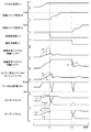
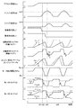
図9および図10は、バッテリ50の入出力制限Win,Woutの絶対値が閾値Wref以下で且つVSCオフスイッチ89がオフのときの、アクセル開度Acc,前輪スリップ速度Vsf,後輪スリップ速度Vsr,前輪38a,38bと路面との間の動摩擦係数μf,後輪38c,38dと路面との間の動摩擦係数μr,前輪要求トルクTf*および前輪トルクTf,後輪要求トルクTr*および後輪トルクTr,エンジン22の要求パワーPe*およびパワーPe,モータMG1,MG2,MG3の総消費電力Pm,モータMG2のトルクTm2,トルク制限Tm2min,Tm2max,モータMG3のトルクTm3,トルク制限Tm3min,Tm3maxの時間変化の様子を模式的に示す説明図である。
9 and 10 show the accelerator opening degree Acc, the front wheel slip speed Vsf, and the rear wheel slip speed Vsr when the absolute values of the input / output limits Win and Wout of the
図9は、実施例の様子を示し、図10は、比較例の様子を示す。比較例としては、前輪スリップ速度Vsfから目標前輪スリップ速度Vsf*を減じた値(Vsf−Vsf*)の増加に伴って前輪要求トルクTf*を徐々に小さくすると共に後輪スリップ速度Vsrから目標後輪スリップ速度Vsr*を減じた値(Vsr−Vsr*)の増加に伴って後輪要求トルクTr*を徐々に小さくする比較例制御を行なう場合を考えるものとした。 FIG. 9 shows a state of the example, and FIG. 10 shows a state of the comparative example. As a comparative example, the front wheel required torque Tf * is gradually decreased as the value obtained by subtracting the target front wheel slip speed Vsf * from the front wheel slip speed Vsf (Vsf−Vsf *) and the target rear wheel slip speed Vsr A case is considered in which comparative example control is performed in which the rear wheel required torque Tr * is gradually decreased as the value obtained by reducing the wheel slip speed Vsr * (Vsr−Vsr *) increases.
比較例の場合、図10に示すように、時刻t21に前輪38a,38bの空転によるスリップが生じると、値(Vsf−Vsf*)がある程度増加した時刻t22から値(Vsf−Vsf*)の増加に伴って前輪要求トルクTf*を徐々に低下させ、これに応じてエンジン22の要求パワーPe*を徐々に低下させる。このとき、エンジン22の応答性が比較的低いために、エンジン22のパワーPeの低下が遅れ、モータMG1の消費電力Pm1の増加(発電電力の低下)が遅れる。そして、このモータMG1の消費電力Pm1の増加の遅れと、モータMG2の回転数Nm2の増加とにより、トルク制限Tm2minが大きくなる(絶対値としては小さくなる、即ち、値0に近づく)。これは、バッテリ50への入力電力が入力制限Winを超過しないようにするためである。いま、入力制限Winの絶対値が閾値Wref以下のときを考えているから、トルク制限Tm2minの絶対値が非常に小さくなることがある。こうした理由により、モータMG2のトルクTm2を十分に小さくすることができず、前輪スリップ速度Vsfが目標前輪スリップ速度Vsf*に対してオーバーシュートすることがある。なお、前輪スリップ速度Vsfの増加時には、モータMG2の回転数Nm2の増加により、トルク制限Tm2maxの絶対値も小さくなる。
In the case of the comparative example, as shown in FIG. 10, when slip occurs due to idling of the
そして、時刻t23に前輪スリップ速度Vsfがピークとなり、その後に前輪スリップ速度Vsfが低下し始めると、値(Vsf−Vsf*)の低下に伴って前輪要求トルクTf*を増加させ、これに応じてエンジン22の要求パワーPe*を増加させる。しかし、エンジン22の低応答性のために、エンジン22のパワーPeの増加が遅れ、モータMG1の消費電力Pm1の低下(発電電力の増加)が遅れる。そして、モータMG1の消費電力Pm1の低下の遅れにより、トルク制限Tm2maxの増加も遅れる。このトルク制限Tm2maxは、バッテリ50からの出力電力が出力制限Woutを超過しないようにするために定められるものである。いま、出力制限Woutの絶対値が閾値Wref以下のときを考えているから、トルク制限Tm2maxの絶対値が非常に小さいことがある。こうした理由により、モータMG2のトルクTm2を十分に大きくすることができず、前輪スリップ速度Vsfが目標前輪スリップ速度Vsf*に対してアンダーシュートし、ひいては、スリップが解消することがある。
Then, when the front wheel slip speed Vsf reaches a peak at time t23 and thereafter the front wheel slip speed Vsf starts to decrease, the front wheel required torque Tf * is increased with a decrease in the value (Vsf−Vsf *). The required power Pe * of the
前輪38a,38bの空転によるスリップが解消した後の時刻t24に、前輪38a,38bの空転によるスリップが再度生じると、上述の比較例の制御により、前輪スリップ速度Vsfが目標前輪スリップ速度Vsf*に対して再度オーバーシュートおよびアンダーシュートし得る。
If slip due to idling of the
比較例の場合、このように前輪スリップ速度Vsfが目標前輪スリップ速度Vsf*に対してオーバーシュートとアンダーシュートとを繰り返す、即ち、前輪スリップ速度Vsfが安定しないことがある。なお、図10では、後輪スリップ速度Vsrは、目標後輪スリップ速度Vsr*をオーバーシュートしていないが、前輪スリップ速度Vsfと同様に、安定していないことが分かる。 In the case of the comparative example, the front wheel slip speed Vsf repeats overshoot and undershoot with respect to the target front wheel slip speed Vsf * as described above, that is, the front wheel slip speed Vsf may not be stabilized. In FIG. 10, the rear wheel slip speed Vsr does not overshoot the target rear wheel slip speed Vsr *, but it is understood that the rear wheel slip speed Vsr is not stable like the front wheel slip speed Vsf.
実施例の場合、図9に示すように、時刻t11に前輪38a,38bの空転によるスリップが生じると、前輪上限トルクTfmaxにより前輪要求トルクTf*を低下させる。実施例では、前輪38a,38bのスリップ開始直後には、式(10)におけるフィードバック項(特に積分項)の影響が十分に小さいために前輪上限トルクTfmaxが前輪釣合トルクTbfに略等しい値となり、この前輪上限トルクTfmaxによって前輪要求トルクTf*が制限されることにより、前輪スリップ速度Vsfをある程度の値で収束させることができる。ところで、実施例では、前輪38a,38bのスリップ開始直後(前輪スリップ速度Vsfがそれほど大きくないとき)に前輪要求トルクTf*を低下させ始めてエンジン22の要求パワーPe*も低下させ始めるから、比較例に比して、トルク制限Tm2minがある程度大きくなる(絶対値としてはある程度小さくなる)前にモータMG2のトルクTm2を低下させることができる。これにより、モータMG2のトルクTm2を十分に低下させることができ、前輪スリップ速度Vsfが目標前輪スリップ速度Vsf*をオーバーシュートするのを抑制することができる。なお、実施例でも、モータMG1の消費電力Pm1の増加(発電電力の低下)の遅れと、モータMG2の回転数Nm2の増加とにより、トルク制限Tm2minの絶対値が小さくなっており、モータMG2の回転数Nm2の増加により、トルク制限Tm2maxの絶対値が小さくなっている。
In the case of the embodiment, as shown in FIG. 9, when slip occurs due to idling of the
そして、その後、式(10)におけるフィードバック項(特に積分項)の影響が大きくなって前輪上限トルクTfmaxが差分(Vsf*−Vsf)を値0に近づけるための値となり、この前輪上限トルクTfmaxによって前輪要求トルクTf*が制限されることにより、前輪スリップ速度Vsfを目標前輪スリップ速度Vsf*に滑らかに近づけてその付近で略一定にすることができる。なお、このときには、フィードバック項(特に積分項)の影響によって前輪上限トルクTfmaxを滑らかに変化させることにより、エンジン22の応答遅れによる不都合を生じさせずに、前輪スリップ速度Vsfを目標前輪スリップ速度Vsf*に近づけることができる。
After that, the influence of the feedback term (particularly the integral term) in the equation (10) becomes large, and the front wheel upper limit torque Tfmax becomes a value for bringing the difference (Vsf * −Vsf) close to the
こうした制御により、前輪スリップ速度Vsfが目標前輪スリップ速度Vsf*に対してオーバーシュートしたりアンダーシュートしたりするのを抑制することができる。即ち、前輪スリップ速度Vsfを目標前輪スリップ速度Vsf*付近でより安定させることができる。 By such control, it is possible to suppress the front wheel slip speed Vsf from overshooting or undershooting the target front wheel slip speed Vsf *. That is, the front wheel slip speed Vsf can be more stabilized near the target front wheel slip speed Vsf *.
時刻t12に後輪38c,38dの空転によるスリップが生じたときには、前輪38a,38bの空転によるスリップが生じたときの前輪要求トルクTf*と同様に後輪要求トルクTr*を変化させることにより、後輪スリップ速度Vsrが目標後輪スリップ速度Vsr*に対してオーバーシュートしたりアンダーシュートしたりするのを抑制することができる。即ち、後輪スリップ速度Vsrを目標後輪スリップ速度Vsr*付近でより安定させることができる。
When slipping due to idling of the
以上説明した実施例のハイブリッド自動車20によれば、VSCオフスイッチ89がオンのときにおいて、前輪38a,38bの空転によるスリップが生じたときには、その開始直後(前輪スリップ速度Vsfがそれほど大きくないとき)に前輪要求トルクTf*を低下させ始めてエンジン22の要求パワーPe*も低下させ始めるから、前輪スリップ速度Vsfが目標前輪スリップ速度Vsf*をオーバーシュートするのを抑制することができる。そして、前輪38a,38bと路面との間の動摩擦力と釣り合う前輪釣合トルクTbfに基づく前輪上限トルクTfmax以下の範囲内で前輪要求トルクTf*を設定するから、前輪スリップ速度Vsfをある程度の値で安定させることができる。同様に、後輪38c,38dの空転によるスリップが生じたときには、その開始直後に後輪要求トルクTr*を低下させ始めるから、後輪スリップ速度Vsrが目標後輪スリップ速度Vsr*をオーバーシュートするのを抑制することができ、後輪38c,38dと路面との間の動摩擦力と釣り合う後輪釣合トルクTbrに基づく後輪上限トルクTrmax以下の範囲内で後輪要求トルクTr*を設定するから、後輪スリップ速度Vsrをある程度の値で安定させることができる。これらの結果、運転者に与えるスリップ感を向上させることができる。
According to the
そして、前輪釣合トルクTbfと、目標前輪スリップ速度Vsf*と前輪スリップ速度Vsfとの差分(Vsf*−Vsf)を打ち消すためのフィードバック項と、の和を前輪上限トルクTfmaxに設定するから、前輪スリップ速度Vsfを目標前輪スリップ速度Vsf*に近づけてその付近で安定させることができる。同様に、後輪釣合トルクTbrと、目標後輪スリップ速度Vsr*と後輪スリップ速度Vsrとの差分(Vsr*−Vsr)を打ち消すためのフィードバック項と、の和を後輪上限トルクTrmaxに設定するから、後輪スリップ速度Vsrを目標後輪スリップ速度Vsr*に近づけてその付近で安定させることができる。これらの結果、運転者に与えるスリップ感をより向上させることができる。 Since the sum of the front wheel balancing torque Tbf and the feedback term for canceling the difference (Vsf * −Vsf) between the target front wheel slip speed Vsf * and the front wheel slip speed Vsf is set to the front wheel upper limit torque Tfmax, The slip speed Vsf can be brought close to the target front wheel slip speed Vsf * and stabilized in the vicinity thereof. Similarly, the sum of the rear wheel upper limit torque Trmax is the sum of the rear wheel balancing torque Tbr and the feedback term for canceling the difference (Vsr * −Vsr) between the target rear wheel slip speed Vsr * and the rear wheel slip speed Vsr. Therefore, the rear wheel slip speed Vsr can be brought close to the target rear wheel slip speed Vsr * and stabilized in the vicinity thereof. As a result, the slip feeling given to the driver can be further improved.
実施例のハイブリッド自動車20では、VSCオフスイッチ89がオンのときにおいて、バッテリ50の入出力制限Win,Woutの絶対値が閾値Wref以下で且つ前輪38a,38bの空転によるスリップが生じたときに、前輪釣合トルクTbfに基づく前輪上限トルクTfmax以下の範囲内で前輪要求トルクTf*を設定してエンジン22とモータMG1,MG2とを制御するものとしたが、バッテリ50の入出力制限Win,Woutの絶対値が閾値Wrefより大きく且つ前輪38a,38bの空転によるスリップが生じたときも、実施例と同様に、前輪釣合トルクTbfに基づく前輪上限トルクTfmax以下の範囲内で前輪要求トルクTf*を設定してエンジン22とモータMG1,MG2とを制御するものとしてもよい。また、バッテリ50の入出力制限Win,Woutの絶対値が閾値Wrefより大きく且つ前輪38a,38bの空転によるスリップが生じたときに、上述の比較例の制御を行なっても前輪スリップ速度Vsfが目標前輪スリップ速度Vsf*に対してオーバーシュートやアンダーシュートしないと想定されるのであれば、上述の比較例の制御を行なうものとしてもよい。ところで、後輪38c,38dの空転によるスリップが生じたときには、走行性や姿勢安定性を考慮して、前輪38a,38bの空転によるスリップが生じたときと同様の制御を行なうのが好ましい。
In the
実施例のハイブリッド自動車20では、前輪38a,38bの空転によるスリップが生じたときの、差分(Vsf*−Vsf)を打ち消すためのフィードバック項には、比例項と積分項とを用いるものとしたが、積分項だけを用いるものとしてもよい。同様に、実施例では、後輪38c,38dの空転によるスリップが生じたときの、差分(Vsr*−Vsr)を打ち消すためのフィードバック項には、比例項と積分項とを用いるものとしたが、積分項だけを用いるものとしてもよい。
In the
実施例のハイブリッド自動車20では、前輪38a,38bの空転によるスリップが生じたときには、前輪釣合トルクTbfと、差分(Vsf*−Vsf)を打ち消すためのフィードバック項と、の和を前輪上限トルクTfmaxに設定するものとしたが、前輪釣合トルクTbfを前輪上限トルクTfmaxに設定するものとしてもよい。この場合でも、前輪スリップ速度Vsfをある程度の速度で安定させることができる。同様に、実施例では、後輪38c,38dの空転によるスリップが生じたときには、後輪釣合トルクTbrと、差分(Vsr*−Vsr)を打ち消すためのフィードバック項と、の和を後輪上限トルクTrmaxに設定するものとしたが、後輪釣合トルクTbrを後輪上限トルクTrmaxに設定するものとしてもよい。この場合でも、後輪スリップ速度Vsrをある程度の速度で安定させることができる。
In the
実施例のハイブリッド自動車20では、エンジン22の推定出力トルクTeestは、今回にVSCオフ時駆動制御ルーチンを実行しときに設定したエンジン22の目標トルクTe*に応答遅れ補償(むだ時間補償や一次遅れ補償)を施して設定するものとしたが、前回にVSCオフ時駆動制御ルーチンを実行しときに設定したモータMG1のトルク指令(前回Tm1*)とプラネタリギヤ30のギヤ比ρとを用いて次式(15)により計算するものとしてもよい。
In the
Teest=-(1+ρ)・前回Tm1*/ρ (15) Teest =-(1 + ρ) ・ previous Tm1 * / ρ (15)
実施例のハイブリッド自動車20では、前輪38a,38bや後輪38c,38dの空転によるスリップが生じているときに、前輪要求トルクTf*と後輪要求トルクTr*とを用いて計算した想定後輪分配比Dresが最大後輪分配比Drmaxより大きいときには、前輪分配比,後輪分配比がそれぞれ値(1−Drmax),最大後輪分配比Drmaxとなるように後輪要求トルクTr*を再設定するものとしたが、こうした後輪要求トルクTr*の再設定を行なわないものとしてもよい。
In the
実施例のハイブリッド自動車20では、前輪38a,38bに連結された駆動軸36Fにプラネタリギヤ30を介して接続されたエンジン22およびモータMG1と、駆動軸36に接続されたモータMG2と、後輪38c,38dに連結された駆動軸36Rに接続されたモータMG3と、を備えるものとしたが、モータMG3を備えないものとしてもよい。即ち、実施例のハイブリッド自動車20では、4輪駆動のハイブリッド自動車としたが、2輪駆動のハイブリッド自動車としてもよいのである。
In the
実施例の主要な要素と課題を解決するための手段の欄に記載した発明の主要な要素との対応関係について説明する。実施例では、エンジン22が「エンジン」に相当し、モータMG1が「第1モータ」に相当し、プラネタリギヤ30が「プラネタリギヤ」に相当し、モータMG2が「第2モータ」に相当し、バッテリ50が「バッテリ」に相当し、HVECU70とエンジンECU24とモータECU40とが「制御手段」に相当する。
The correspondence between the main elements of the embodiment and the main elements of the invention described in the column of means for solving the problems will be described. In the embodiment, the
なお、実施例の主要な要素と課題を解決するための手段の欄に記載した発明の主要な要素との対応関係は、実施例が課題を解決するための手段の欄に記載した発明を実施するための形態を具体的に説明するための一例であることから、課題を解決するための手段の欄に記載した発明の要素を限定するものではない。即ち、課題を解決するための手段の欄に記載した発明についての解釈はその欄の記載に基づいて行なわれるべきものであり、実施例は課題を解決するための手段の欄に記載した発明の具体的な一例に過ぎないものである。 The correspondence between the main elements of the embodiment and the main elements of the invention described in the column of means for solving the problem is the same as that of the embodiment described in the column of means for solving the problem. Therefore, the elements of the invention described in the column of means for solving the problems are not limited. That is, the interpretation of the invention described in the column of means for solving the problems should be made based on the description of the column, and the examples are those of the invention described in the column of means for solving the problems. It is only a specific example.
以上、本発明を実施するための形態について実施例を用いて説明したが、本発明はこうした実施例に何等限定されるものではなく、本発明の要旨を逸脱しない範囲内において、種々なる形態で実施し得ることは勿論である。 As mentioned above, although the form for implementing this invention was demonstrated using the Example, this invention is not limited at all to such an Example, In the range which does not deviate from the summary of this invention, it is with various forms. Of course, it can be implemented.
本発明は、ハイブリッド自動車の製造産業などに利用可能である。 The present invention can be used in the manufacturing industry of hybrid vehicles.
20 ハイブリッド自動車、22 エンジン、23 クランクポジションセンサ、24 エンジン用電子制御ユニット(エンジンECU)、26 クランクシャフト、30 プラネタリギヤ、36F,36R 駆動軸、37F,37R デファレンシャルギヤ、38a,38b 前輪、38c,38d 後輪、40 モータ用電子制御ユニット(モータECU)、41,42,43 インバータ、44,45,46 回転位置検出センサ、50 バッテリ、51a 電圧センサ、51b 電流センサ、51c 温度センサ、52 バッテリ用電子制御ユニット(バッテリECU)、70 ハイブリッド用電子制御ユニット(HVECU)、80 イグニッションスイッチ、81 シフトレバー、82 シフトポジションセンサ、83 アクセルペダル、84 アクセルペダルポジションセンサ、85 ブレーキペダル、86 ブレーキペダルポジションセンサ、88 加速度センサ、89 姿勢保持制御オフスイッチ(VSCオフスイッチ)、92 マスタシリンダ、94 ブレーキアクチュエータ、96a〜96d ブレーキホイールシリンダ、98 ブレーキ用電子制御ユニット(ブレーキECU)、99a〜99d 車輪速センサ、99st 操舵角センサ、MG1,MG2,MG3 モータ。 20 hybrid vehicle, 22 engine, 23 crank position sensor, 24 engine electronic control unit (engine ECU), 26 crankshaft, 30 planetary gear, 36F, 36R drive shaft, 37F, 37R differential gear, 38a, 38b front wheel, 38c, 38d Rear wheel, 40 motor electronic control unit (motor ECU), 41, 42, 43 inverter, 44, 45, 46 rotational position detection sensor, 50 battery, 51a voltage sensor, 51b current sensor, 51c temperature sensor, 52 battery electronics Control unit (battery ECU), 70 Hybrid electronic control unit (HVECU), 80 Ignition switch, 81 Shift lever, 82 Shift position sensor, 83 Accelerator pedal, 84 Xel pedal position sensor, 85 brake pedal, 86 brake pedal position sensor, 88 acceleration sensor, 89 attitude hold control off switch (VSC off switch), 92 master cylinder, 94 brake actuator, 96a to 96d brake wheel cylinder, 98 brake electronics Control unit (brake ECU), 99a to 99d wheel speed sensor, 99st steering angle sensor, MG1, MG2, MG3 motor.
Claims (6)
動力を入出力可能な第1モータと、
前記第1モータの回転軸と前記エンジンの出力軸と駆動輪に連結された駆動軸とに、3つの回転要素が、共線図において前記回転軸,前記出力軸,前記駆動軸の順に並ぶように接続されたプラネタリギヤと、
前記駆動軸に動力を入出力可能な第2モータと、
前記第1モータおよび前記第2モータと電力をやりとり可能なバッテリと、
前記バッテリの許容入出力電力の範囲内で走行するように前記エンジンと前記第1モータと前記第2モータとを制御する制御手段と、
を備えるハイブリッド自動車であって、
前記制御手段は、前記駆動輪の空転によるスリップが生じたときには、前記駆動輪と路面との間の動摩擦力と釣り合う釣合駆動力と、前記駆動輪の目標スリップ速度と現在のスリップ速度との差分であるスリップ差分が打ち消されるようにするための補正駆動力と、の和を上限駆動力に設定し、該上限駆動力以下の駆動力が前記駆動輪に出力されるように前記エンジンと前記第1モータと前記第2モータとを制御する手段である、
ことを特徴とするハイブリッド自動車。 Engine,
A first motor capable of inputting and outputting power;
Three rotating elements are arranged in the order of the rotating shaft, the output shaft, and the driving shaft in the alignment chart on the rotating shaft of the first motor, the output shaft of the engine, and the driving shaft connected to the driving wheel. Planetary gear connected to the
A second motor capable of inputting and outputting power to the drive shaft;
A battery capable of exchanging electric power with the first motor and the second motor;
Control means for controlling the engine, the first motor, and the second motor so as to run within a range of allowable input / output power of the battery;
A hybrid vehicle comprising:
When a slip occurs due to idling of the drive wheel, the control means determines a balance drive force that balances a dynamic friction force between the drive wheel and a road surface, a target slip speed of the drive wheel, and a current slip speed. The sum of the correction driving force for canceling out the slip difference, which is the difference, is set as the upper limit driving force, and the engine and the engine so that the driving force equal to or lower than the upper limit driving force is output to the driving wheels. Means for controlling the first motor and the second motor;
A hybrid vehicle characterized by that.
前記制御手段は、少なくとも前記許容入出力電力の絶対値が所定値以下のときに、前記駆動輪の空転によるスリップが生じたときには、前記上限駆動力以下の駆動力が前記駆動輪に出力されるように制御する手段である、
ことを特徴とするハイブリッド自動車。 The hybrid vehicle according to claim 1 ,
The control means outputs a driving force equal to or less than the upper limit driving force to the driving wheel when a slip occurs due to idling of the driving wheel when at least the absolute value of the allowable input / output power is not more than a predetermined value. Is a means to control,
A hybrid vehicle characterized by that.
前記駆動輪とは異なる第2駆動輪に連結された第2駆動軸に動力を入出力可能であると共に前記バッテリと電力をやりとり可能な第3モータを更に備え、
前記制御手段は、前記バッテリの最大許容入出力電力の範囲内で走行するように前記エンジンと前記第1モータと前記第2モータと前記第3モータとを制御する手段であり、
更に、前記制御手段は、前記第2駆動輪の空転によるスリップが生じたときには、前記第2駆動輪と路面との間の動摩擦力と釣り合う第2釣合駆動力に基づいて第2上限駆動力を設定し、該第2上限駆動力以下の駆動力が前記第2駆動輪に出力されるように前記第3モータを制御する手段である、
ことを特徴とするハイブリッド自動車。 A hybrid vehicle according to claim 1 or 2 ,
A third motor capable of inputting / outputting power to / from a second drive shaft coupled to a second drive wheel different from the drive wheel and capable of exchanging electric power with the battery;
The control means is means for controlling the engine, the first motor, the second motor, and the third motor so as to run within a range of the maximum allowable input / output power of the battery,
Further, when slippage occurs due to the idling of the second drive wheel, the control means has a second upper limit drive force based on a second balance drive force that balances the dynamic friction force between the second drive wheel and the road surface. And controlling the third motor so that a driving force equal to or less than the second upper limit driving force is output to the second driving wheel.
A hybrid vehicle characterized by that.
前記制御手段は、前記第2駆動輪の空転によるスリップが生じたときには、前記第2釣合駆動力と、前記第2駆動輪の目標スリップ速度と現在のスリップ速度との差分である第2スリップ差分が打ち消されるようにするための第2補正駆動力と、の和を前記第2上限駆動力に設定する手段である、
ことを特徴とするハイブリッド自動車。 A hybrid vehicle according to claim 3 ,
When a slip occurs due to idling of the second drive wheel, the control means is a second slip that is a difference between the second balance driving force, a target slip speed of the second drive wheel, and a current slip speed. A means for setting a sum of the second correction driving force and the second upper limit driving force for canceling the difference to the second upper limit driving force;
A hybrid vehicle characterized by that.
前記制御手段は、少なくとも前記許容入出力電力の絶対値が所定値以下のときに、前記駆動輪の空転によるスリップが生じたときには、前記上限駆動力以下の駆動力が前記駆動輪に出力されるように制御する手段である、
ことを特徴とするハイブリッド自動車。 The hybrid vehicle according to claim 3 or 4 ,
The control means outputs a driving force equal to or less than the upper limit driving force to the driving wheel when a slip occurs due to idling of the driving wheel when at least the absolute value of the allowable input / output power is not more than a predetermined value. Is a means to control,
A hybrid vehicle characterized by that.
前記制御手段は、前記駆動輪と前記第2駆動輪とのいずれか一方または両方に空転によるスリップが生じたときには、前記駆動輪のトルクと前記第2駆動輪のトルクの分配比が許容範囲内となるように制御する手段である、
ことを特徴とするハイブリッド自動車。
A hybrid vehicle according to any one of claims 3 to 5 ,
When the slip due to idling occurs in one or both of the driving wheel and the second driving wheel, the control means has a distribution ratio between the torque of the driving wheel and the torque of the second driving wheel within an allowable range. It is a means to control so that
A hybrid vehicle characterized by that.
Priority Applications (2)
| Application Number | Priority Date | Filing Date | Title |
|---|---|---|---|
| JP2014227136A JP6183333B2 (en) | 2014-11-07 | 2014-11-07 | Hybrid car |
| US14/933,845 US9643594B2 (en) | 2014-11-07 | 2015-11-05 | Hybrid car |
Applications Claiming Priority (1)
| Application Number | Priority Date | Filing Date | Title |
|---|---|---|---|
| JP2014227136A JP6183333B2 (en) | 2014-11-07 | 2014-11-07 | Hybrid car |
Publications (2)
| Publication Number | Publication Date |
|---|---|
| JP2016088381A JP2016088381A (en) | 2016-05-23 |
| JP6183333B2 true JP6183333B2 (en) | 2017-08-23 |
Family
ID=55911603
Family Applications (1)
| Application Number | Title | Priority Date | Filing Date |
|---|---|---|---|
| JP2014227136A Expired - Fee Related JP6183333B2 (en) | 2014-11-07 | 2014-11-07 | Hybrid car |
Country Status (2)
| Country | Link |
|---|---|
| US (1) | US9643594B2 (en) |
| JP (1) | JP6183333B2 (en) |
Families Citing this family (13)
| Publication number | Priority date | Publication date | Assignee | Title |
|---|---|---|---|---|
| JP6540580B2 (en) * | 2016-04-11 | 2019-07-10 | トヨタ自動車株式会社 | Vehicle control device |
| JP6800659B2 (en) * | 2016-08-25 | 2020-12-16 | 株式会社東芝 | Hybrid vehicle system |
| JP6776502B2 (en) * | 2016-09-23 | 2020-10-28 | 日立オートモティブシステムズ株式会社 | Electric vehicle controls, control methods and control systems |
| JP7017895B2 (en) * | 2017-09-28 | 2022-02-09 | 株式会社Subaru | Vehicle driving force control device |
| JP7017894B2 (en) * | 2017-09-28 | 2022-02-09 | 株式会社Subaru | Vehicle driving force control device |
| CN109572673B (en) * | 2017-09-29 | 2020-12-25 | 比亚迪股份有限公司 | Hybrid electric vehicle, power system thereof and whole vehicle control method |
| JP7043908B2 (en) * | 2018-03-15 | 2022-03-30 | トヨタ自動車株式会社 | Power generation control method for vehicles equipped with power generation equipment and vehicle-mounted power generation equipment |
| JP6984558B2 (en) * | 2018-07-26 | 2021-12-22 | トヨタ自動車株式会社 | Vehicle driving support device |
| JP2020041481A (en) * | 2018-09-11 | 2020-03-19 | 川崎重工業株式会社 | Power generation system and propulsion device including the same |
| JP7300362B2 (en) * | 2019-10-07 | 2023-06-29 | 株式会社Subaru | electric vehicle |
| KR102720112B1 (en) * | 2019-12-16 | 2024-10-23 | 현대자동차주식회사 | Eco-friendly vehicle and method of controlling driving force for the same |
| CN113442907B (en) * | 2020-03-24 | 2023-12-01 | 广州汽车集团股份有限公司 | A method and device for controlling vehicle speed under low-speed conditions |
| JP7725883B2 (en) * | 2021-06-16 | 2025-08-20 | 日産自動車株式会社 | Hybrid vehicle control method and hybrid vehicle control device |
Family Cites Families (19)
| Publication number | Priority date | Publication date | Assignee | Title |
|---|---|---|---|---|
| JP2001105919A (en) * | 1999-10-08 | 2001-04-17 | Toyota Motor Corp | Control device for front and rear wheel drive vehicles |
| JP4157504B2 (en) * | 2004-03-30 | 2008-10-01 | トヨタ自動車株式会社 | POWER OUTPUT DEVICE, HYBRID VEHICLE HAVING THE SAME, AND METHOD FOR CONTROLLING POWER OUTPUT DEVICE |
| JP4637770B2 (en) * | 2006-03-01 | 2011-02-23 | 三菱ふそうトラック・バス株式会社 | Control device for hybrid electric vehicle |
| JP2007245805A (en) * | 2006-03-14 | 2007-09-27 | Mitsubishi Fuso Truck & Bus Corp | Control device for hybrid electric vehicle |
| JP4770756B2 (en) * | 2007-02-27 | 2011-09-14 | トヨタ自動車株式会社 | Vehicle and control method thereof |
| JP4976990B2 (en) * | 2007-11-22 | 2012-07-18 | トヨタ自動車株式会社 | HYBRID VEHICLE, ITS CONTROL METHOD, AND DRIVE DEVICE |
| JP2009165326A (en) * | 2008-01-10 | 2009-07-23 | Toyota Motor Corp | Vehicle and control method thereof |
| JP2009190564A (en) * | 2008-02-14 | 2009-08-27 | Toyota Motor Corp | Vehicle control device |
| JP5093365B2 (en) * | 2009-05-27 | 2012-12-12 | トヨタ自動車株式会社 | Hybrid vehicle drive control apparatus and method |
| WO2013076902A1 (en) * | 2011-11-25 | 2013-05-30 | 日産自動車株式会社 | Drive control device for vehicle and drive control method for vehicle |
| US9227620B2 (en) * | 2012-03-15 | 2016-01-05 | Nissan Motor Co., Ltd. | Engine start control device and engine start control method for hybrid electric vehicle |
| JP5824406B2 (en) * | 2012-04-20 | 2015-11-25 | 日立建機株式会社 | Electric drive vehicle |
| US9556590B2 (en) * | 2012-06-04 | 2017-01-31 | Hitachi Construction Machinery Co., Ltd. | Construction vehicle |
| JP6115371B2 (en) * | 2013-07-22 | 2017-04-19 | 株式会社デンソー | Vehicle control device |
| MX352115B (en) * | 2013-07-29 | 2017-11-09 | Nissan Motor | Vehicle regenerative braking control device. |
| KR101509988B1 (en) * | 2013-11-26 | 2015-04-07 | 현대자동차주식회사 | Method for controlling four wheel driving of vehicle |
| US9680407B2 (en) * | 2014-05-20 | 2017-06-13 | Mitsubishi Electric Corporation | Electric motor control device |
| US20160009311A1 (en) * | 2014-07-09 | 2016-01-14 | ZF Steering Systems, LLC | Friction clutch for steering column |
| US9579991B2 (en) * | 2014-10-02 | 2017-02-28 | Ford Global Technologies, Llc | Vehicle system and method for controlling torque delivery during transmission engagements with road grade and mass estimation |
-
2014
- 2014-11-07 JP JP2014227136A patent/JP6183333B2/en not_active Expired - Fee Related
-
2015
- 2015-11-05 US US14/933,845 patent/US9643594B2/en not_active Expired - Fee Related
Also Published As
| Publication number | Publication date |
|---|---|
| US9643594B2 (en) | 2017-05-09 |
| JP2016088381A (en) | 2016-05-23 |
| US20160129901A1 (en) | 2016-05-12 |
Similar Documents
| Publication | Publication Date | Title |
|---|---|---|
| JP6183333B2 (en) | Hybrid car | |
| JP6107792B2 (en) | Automobile | |
| JP5856465B2 (en) | vehicle | |
| JP6075355B2 (en) | Automobile | |
| JP2016088380A (en) | Hybrid car | |
| JP4479458B2 (en) | Vehicle and control method thereof | |
| JP2019156007A (en) | Control device for hybrid vehicle | |
| JP4196962B2 (en) | Car | |
| JP4089608B2 (en) | Car | |
| JP6331981B2 (en) | Automobile | |
| JP5556586B2 (en) | Hybrid car | |
| JP5672054B2 (en) | Hybrid vehicle and control method thereof | |
| JP6036546B2 (en) | Hybrid car | |
| JP5880404B2 (en) | Hybrid car | |
| JP2019131137A (en) | Hybrid vehicle | |
| JP4066985B2 (en) | Power output apparatus, automobile equipped with the same, and control method of power output apparatus | |
| JP2017178013A (en) | Hybrid car | |
| JP2017088029A (en) | Hybrid car | |
| JP4301252B2 (en) | POWER OUTPUT DEVICE, ITS CONTROL METHOD, AND VEHICLE | |
| JP6493252B2 (en) | Hybrid car | |
| JP4566110B2 (en) | Vehicle, power output device, vehicle control method, and power output device control method | |
| JP2013189034A (en) | Hybrid vehicle | |
| CN100363198C (en) | Power output device, its control method and automobile | |
| JP2012218577A (en) | Hybrid vehicle | |
| JP7013837B2 (en) | Hybrid vehicle |
Legal Events
| Date | Code | Title | Description |
|---|---|---|---|
| A621 | Written request for application examination |
Free format text: JAPANESE INTERMEDIATE CODE: A621 Effective date: 20160303 |
|
| A977 | Report on retrieval |
Free format text: JAPANESE INTERMEDIATE CODE: A971007 Effective date: 20161226 |
|
| A131 | Notification of reasons for refusal |
Free format text: JAPANESE INTERMEDIATE CODE: A131 Effective date: 20170110 |
|
| A521 | Request for written amendment filed |
Free format text: JAPANESE INTERMEDIATE CODE: A523 Effective date: 20170213 |
|
| TRDD | Decision of grant or rejection written | ||
| A01 | Written decision to grant a patent or to grant a registration (utility model) |
Free format text: JAPANESE INTERMEDIATE CODE: A01 Effective date: 20170627 |
|
| A61 | First payment of annual fees (during grant procedure) |
Free format text: JAPANESE INTERMEDIATE CODE: A61 Effective date: 20170710 |
|
| R151 | Written notification of patent or utility model registration |
Ref document number: 6183333 Country of ref document: JP Free format text: JAPANESE INTERMEDIATE CODE: R151 |
|
| LAPS | Cancellation because of no payment of annual fees |