JP5093365B2 - Hybrid vehicle drive control apparatus and method - Google Patents
Hybrid vehicle drive control apparatus and method Download PDFInfo
- Publication number
- JP5093365B2 JP5093365B2 JP2010546753A JP2010546753A JP5093365B2 JP 5093365 B2 JP5093365 B2 JP 5093365B2 JP 2010546753 A JP2010546753 A JP 2010546753A JP 2010546753 A JP2010546753 A JP 2010546753A JP 5093365 B2 JP5093365 B2 JP 5093365B2
- Authority
- JP
- Japan
- Prior art keywords
- state
- generator
- oil
- hybrid vehicle
- lock mechanism
- Prior art date
- Legal status (The legal status is an assumption and is not a legal conclusion. Google has not performed a legal analysis and makes no representation as to the accuracy of the status listed.)
- Expired - Fee Related
Links
Images


Classifications
-
- B—PERFORMING OPERATIONS; TRANSPORTING
- B60—VEHICLES IN GENERAL
- B60W—CONJOINT CONTROL OF VEHICLE SUB-UNITS OF DIFFERENT TYPE OR DIFFERENT FUNCTION; CONTROL SYSTEMS SPECIALLY ADAPTED FOR HYBRID VEHICLES; ROAD VEHICLE DRIVE CONTROL SYSTEMS FOR PURPOSES NOT RELATED TO THE CONTROL OF A PARTICULAR SUB-UNIT
- B60W10/00—Conjoint control of vehicle sub-units of different type or different function
- B60W10/10—Conjoint control of vehicle sub-units of different type or different function including control of change-speed gearings
-
- B—PERFORMING OPERATIONS; TRANSPORTING
- B60—VEHICLES IN GENERAL
- B60K—ARRANGEMENT OR MOUNTING OF PROPULSION UNITS OR OF TRANSMISSIONS IN VEHICLES; ARRANGEMENT OR MOUNTING OF PLURAL DIVERSE PRIME-MOVERS IN VEHICLES; AUXILIARY DRIVES FOR VEHICLES; INSTRUMENTATION OR DASHBOARDS FOR VEHICLES; ARRANGEMENTS IN CONNECTION WITH COOLING, AIR INTAKE, GAS EXHAUST OR FUEL SUPPLY OF PROPULSION UNITS IN VEHICLES
- B60K6/00—Arrangement or mounting of plural diverse prime-movers for mutual or common propulsion, e.g. hybrid propulsion systems comprising electric motors and internal combustion engines ; Control systems therefor, i.e. systems controlling two or more prime movers, or controlling one of these prime movers and any of the transmission, drive or drive units Informative references: mechanical gearings with secondary electric drive F16H3/72; arrangements for handling mechanical energy structurally associated with the dynamo-electric machine H02K7/00; machines comprising structurally interrelated motor and generator parts H02K51/00; dynamo-electric machines not otherwise provided for in H02K see H02K99/00
- B60K6/20—Arrangement or mounting of plural diverse prime-movers for mutual or common propulsion, e.g. hybrid propulsion systems comprising electric motors and internal combustion engines ; Control systems therefor, i.e. systems controlling two or more prime movers, or controlling one of these prime movers and any of the transmission, drive or drive units Informative references: mechanical gearings with secondary electric drive F16H3/72; arrangements for handling mechanical energy structurally associated with the dynamo-electric machine H02K7/00; machines comprising structurally interrelated motor and generator parts H02K51/00; dynamo-electric machines not otherwise provided for in H02K see H02K99/00 the prime-movers consisting of electric motors and internal combustion engines, e.g. HEVs
- B60K6/42—Arrangement or mounting of plural diverse prime-movers for mutual or common propulsion, e.g. hybrid propulsion systems comprising electric motors and internal combustion engines ; Control systems therefor, i.e. systems controlling two or more prime movers, or controlling one of these prime movers and any of the transmission, drive or drive units Informative references: mechanical gearings with secondary electric drive F16H3/72; arrangements for handling mechanical energy structurally associated with the dynamo-electric machine H02K7/00; machines comprising structurally interrelated motor and generator parts H02K51/00; dynamo-electric machines not otherwise provided for in H02K see H02K99/00 the prime-movers consisting of electric motors and internal combustion engines, e.g. HEVs characterised by the architecture of the hybrid electric vehicle
- B60K6/44—Series-parallel type
- B60K6/445—Differential gearing distribution type
-
- B—PERFORMING OPERATIONS; TRANSPORTING
- B60—VEHICLES IN GENERAL
- B60W—CONJOINT CONTROL OF VEHICLE SUB-UNITS OF DIFFERENT TYPE OR DIFFERENT FUNCTION; CONTROL SYSTEMS SPECIALLY ADAPTED FOR HYBRID VEHICLES; ROAD VEHICLE DRIVE CONTROL SYSTEMS FOR PURPOSES NOT RELATED TO THE CONTROL OF A PARTICULAR SUB-UNIT
- B60W20/00—Control systems specially adapted for hybrid vehicles
-
- B—PERFORMING OPERATIONS; TRANSPORTING
- B60—VEHICLES IN GENERAL
- B60K—ARRANGEMENT OR MOUNTING OF PROPULSION UNITS OR OF TRANSMISSIONS IN VEHICLES; ARRANGEMENT OR MOUNTING OF PLURAL DIVERSE PRIME-MOVERS IN VEHICLES; AUXILIARY DRIVES FOR VEHICLES; INSTRUMENTATION OR DASHBOARDS FOR VEHICLES; ARRANGEMENTS IN CONNECTION WITH COOLING, AIR INTAKE, GAS EXHAUST OR FUEL SUPPLY OF PROPULSION UNITS IN VEHICLES
- B60K6/00—Arrangement or mounting of plural diverse prime-movers for mutual or common propulsion, e.g. hybrid propulsion systems comprising electric motors and internal combustion engines ; Control systems therefor, i.e. systems controlling two or more prime movers, or controlling one of these prime movers and any of the transmission, drive or drive units Informative references: mechanical gearings with secondary electric drive F16H3/72; arrangements for handling mechanical energy structurally associated with the dynamo-electric machine H02K7/00; machines comprising structurally interrelated motor and generator parts H02K51/00; dynamo-electric machines not otherwise provided for in H02K see H02K99/00
- B60K6/20—Arrangement or mounting of plural diverse prime-movers for mutual or common propulsion, e.g. hybrid propulsion systems comprising electric motors and internal combustion engines ; Control systems therefor, i.e. systems controlling two or more prime movers, or controlling one of these prime movers and any of the transmission, drive or drive units Informative references: mechanical gearings with secondary electric drive F16H3/72; arrangements for handling mechanical energy structurally associated with the dynamo-electric machine H02K7/00; machines comprising structurally interrelated motor and generator parts H02K51/00; dynamo-electric machines not otherwise provided for in H02K see H02K99/00 the prime-movers consisting of electric motors and internal combustion engines, e.g. HEVs
- B60K6/22—Arrangement or mounting of plural diverse prime-movers for mutual or common propulsion, e.g. hybrid propulsion systems comprising electric motors and internal combustion engines ; Control systems therefor, i.e. systems controlling two or more prime movers, or controlling one of these prime movers and any of the transmission, drive or drive units Informative references: mechanical gearings with secondary electric drive F16H3/72; arrangements for handling mechanical energy structurally associated with the dynamo-electric machine H02K7/00; machines comprising structurally interrelated motor and generator parts H02K51/00; dynamo-electric machines not otherwise provided for in H02K see H02K99/00 the prime-movers consisting of electric motors and internal combustion engines, e.g. HEVs characterised by apparatus, components or means specially adapted for HEVs
- B60K6/26—Arrangement or mounting of plural diverse prime-movers for mutual or common propulsion, e.g. hybrid propulsion systems comprising electric motors and internal combustion engines ; Control systems therefor, i.e. systems controlling two or more prime movers, or controlling one of these prime movers and any of the transmission, drive or drive units Informative references: mechanical gearings with secondary electric drive F16H3/72; arrangements for handling mechanical energy structurally associated with the dynamo-electric machine H02K7/00; machines comprising structurally interrelated motor and generator parts H02K51/00; dynamo-electric machines not otherwise provided for in H02K see H02K99/00 the prime-movers consisting of electric motors and internal combustion engines, e.g. HEVs characterised by apparatus, components or means specially adapted for HEVs characterised by the motors or the generators
- B60K2006/268—Electric drive motor starts the engine, i.e. used as starter motor
-
- B—PERFORMING OPERATIONS; TRANSPORTING
- B60—VEHICLES IN GENERAL
- B60K—ARRANGEMENT OR MOUNTING OF PROPULSION UNITS OR OF TRANSMISSIONS IN VEHICLES; ARRANGEMENT OR MOUNTING OF PLURAL DIVERSE PRIME-MOVERS IN VEHICLES; AUXILIARY DRIVES FOR VEHICLES; INSTRUMENTATION OR DASHBOARDS FOR VEHICLES; ARRANGEMENTS IN CONNECTION WITH COOLING, AIR INTAKE, GAS EXHAUST OR FUEL SUPPLY OF PROPULSION UNITS IN VEHICLES
- B60K6/00—Arrangement or mounting of plural diverse prime-movers for mutual or common propulsion, e.g. hybrid propulsion systems comprising electric motors and internal combustion engines ; Control systems therefor, i.e. systems controlling two or more prime movers, or controlling one of these prime movers and any of the transmission, drive or drive units Informative references: mechanical gearings with secondary electric drive F16H3/72; arrangements for handling mechanical energy structurally associated with the dynamo-electric machine H02K7/00; machines comprising structurally interrelated motor and generator parts H02K51/00; dynamo-electric machines not otherwise provided for in H02K see H02K99/00
- B60K6/20—Arrangement or mounting of plural diverse prime-movers for mutual or common propulsion, e.g. hybrid propulsion systems comprising electric motors and internal combustion engines ; Control systems therefor, i.e. systems controlling two or more prime movers, or controlling one of these prime movers and any of the transmission, drive or drive units Informative references: mechanical gearings with secondary electric drive F16H3/72; arrangements for handling mechanical energy structurally associated with the dynamo-electric machine H02K7/00; machines comprising structurally interrelated motor and generator parts H02K51/00; dynamo-electric machines not otherwise provided for in H02K see H02K99/00 the prime-movers consisting of electric motors and internal combustion engines, e.g. HEVs
- B60K6/22—Arrangement or mounting of plural diverse prime-movers for mutual or common propulsion, e.g. hybrid propulsion systems comprising electric motors and internal combustion engines ; Control systems therefor, i.e. systems controlling two or more prime movers, or controlling one of these prime movers and any of the transmission, drive or drive units Informative references: mechanical gearings with secondary electric drive F16H3/72; arrangements for handling mechanical energy structurally associated with the dynamo-electric machine H02K7/00; machines comprising structurally interrelated motor and generator parts H02K51/00; dynamo-electric machines not otherwise provided for in H02K see H02K99/00 the prime-movers consisting of electric motors and internal combustion engines, e.g. HEVs characterised by apparatus, components or means specially adapted for HEVs
- B60K6/38—Arrangement or mounting of plural diverse prime-movers for mutual or common propulsion, e.g. hybrid propulsion systems comprising electric motors and internal combustion engines ; Control systems therefor, i.e. systems controlling two or more prime movers, or controlling one of these prime movers and any of the transmission, drive or drive units Informative references: mechanical gearings with secondary electric drive F16H3/72; arrangements for handling mechanical energy structurally associated with the dynamo-electric machine H02K7/00; machines comprising structurally interrelated motor and generator parts H02K51/00; dynamo-electric machines not otherwise provided for in H02K see H02K99/00 the prime-movers consisting of electric motors and internal combustion engines, e.g. HEVs characterised by apparatus, components or means specially adapted for HEVs characterised by the driveline clutches
- B60K2006/381—Arrangement or mounting of plural diverse prime-movers for mutual or common propulsion, e.g. hybrid propulsion systems comprising electric motors and internal combustion engines ; Control systems therefor, i.e. systems controlling two or more prime movers, or controlling one of these prime movers and any of the transmission, drive or drive units Informative references: mechanical gearings with secondary electric drive F16H3/72; arrangements for handling mechanical energy structurally associated with the dynamo-electric machine H02K7/00; machines comprising structurally interrelated motor and generator parts H02K51/00; dynamo-electric machines not otherwise provided for in H02K see H02K99/00 the prime-movers consisting of electric motors and internal combustion engines, e.g. HEVs characterised by apparatus, components or means specially adapted for HEVs characterised by the driveline clutches characterized by driveline brakes
-
- Y—GENERAL TAGGING OF NEW TECHNOLOGICAL DEVELOPMENTS; GENERAL TAGGING OF CROSS-SECTIONAL TECHNOLOGIES SPANNING OVER SEVERAL SECTIONS OF THE IPC; TECHNICAL SUBJECTS COVERED BY FORMER USPC CROSS-REFERENCE ART COLLECTIONS [XRACs] AND DIGESTS
- Y02—TECHNOLOGIES OR APPLICATIONS FOR MITIGATION OR ADAPTATION AGAINST CLIMATE CHANGE
- Y02T—CLIMATE CHANGE MITIGATION TECHNOLOGIES RELATED TO TRANSPORTATION
- Y02T10/00—Road transport of goods or passengers
- Y02T10/60—Other road transportation technologies with climate change mitigation effect
- Y02T10/62—Hybrid vehicles
Description
本発明は、ハイブリッド車両の駆動制御装置及び方法の技術分野に関する。 The present invention relates to a technical field of a drive control apparatus and method for a hybrid vehicle.
この種の装置として、動力源として内燃機関に加えて電動機を備えると共に、内燃機関の動力により発電する発電機とこの発電機によって発電される電力を蓄積可能なバッテリを備えるハイブリッド車両が知られている。このようなハイブリッド車両では、内燃機関の動力は、例えばプラネタリギアにより構成される動力分割機構によって、発電機の回転軸と、車軸に連結される駆動軸とに分割される。 As this type of device, there is known a hybrid vehicle that includes an electric motor in addition to an internal combustion engine as a power source, and includes a generator that generates electric power by the power of the internal combustion engine and a battery that can store electric power generated by the generator. Yes. In such a hybrid vehicle, the power of the internal combustion engine is divided into a rotating shaft of the generator and a drive shaft connected to the axle by a power split mechanism constituted by a planetary gear, for example.
このようなハイブリッド車両において、内燃機関から駆動軸へのエネルギーの伝達効率を高めるために、駆動軸に出力すべき目標駆動トルクが内燃機関の最大出力トルクより小さい場合には、発電機の回転軸を機械的にロックして、内燃機関の出力軸と駆動軸とを機械的に直結する技術が知られている。この技術によれば、内燃機関の動力を、発電機や電動機を介することなく、駆動軸に直接出力することができるので、発電機や電動機におけるエネルギー損失の発生を無くすことができ、伝達効率を高めることが可能である。例えば特許文献1等では、発電機の回転軸の機械的なロックが意図せずに開放された場合、それ以降、この発電機の機械的なロックを一律禁止する技術が開示されている。また、特許文献3等では、内燃機関のバルブを制御する油圧制御弁(所謂、OCV:Oil Control Valve)に異物が噛み込まれたことが検出された場合、OCVに印加する電流を最大電流、最小電流と交互に変化させ、オイルポンプによる作動油により異物を流す技術が開示されている。
In such a hybrid vehicle, if the target drive torque to be output to the drive shaft is smaller than the maximum output torque of the internal combustion engine in order to increase the energy transfer efficiency from the internal combustion engine to the drive shaft, the rotating shaft of the generator Is known that mechanically locks the shaft and mechanically directly connects the output shaft and the drive shaft of the internal combustion engine. According to this technology, the power of the internal combustion engine can be directly output to the drive shaft without going through the generator or electric motor, so that the generation of energy loss in the generator or electric motor can be eliminated, and the transmission efficiency can be improved. It is possible to increase. For example,
しかしながら、上述した特許文献1等によれば、ハイブリッド車両における発電機の機械的なロック機構内に異物が混入して、発電機の回転軸の機械的なロック及びロックの開放が適切に実施されない可能性があるという技術的な問題点が生じる。
However, according to the above-described
詳細には、発電機のロック機構は、ロック機構内のオイルの循環によって潤滑されていると共に冷却されている。この循環されるオイルに混じって、発電機のロック機構内に鉄粉等の異物が混入する可能性がある。加えて、発電機のロック機構内の摺動部、回転部、支持部又は押圧部等の構成要素の動作によって、磨耗された鉄粉等の異物が発生する可能性がある。更に、発電機のロック機構内の各構成要素の連結部などにこの異物が堆積してしまう可能性がある。 Specifically, the generator lock mechanism is lubricated and cooled by the circulation of oil in the lock mechanism. There is a possibility that foreign matters such as iron powder may enter the lock mechanism of the generator by being mixed with the circulated oil. In addition, foreign substances such as worn iron powder may be generated by the operation of components such as a sliding portion, a rotating portion, a supporting portion, or a pressing portion in the lock mechanism of the generator. Furthermore, there is a possibility that the foreign matter accumulates on the connecting portion of each component in the lock mechanism of the generator.
これらの異物は、発電機のロック機構内の摺動部等に引っ掛かったり、回転部と支持部との間の摩擦係数を変化させるため、発電機のロック機構において、意図しないロックが実施されてしまったり、ロックが意図しないで開放されてしまったりして、発電機の回転軸の機械的なロック及びロックの開放が適切に実施されない可能性があるという技術的な問題点が生じる。ひいては、この意図しないロック及び意図しないロックの開放に起因して、ハイブリッド車両において、伝達効率及び燃費効率の向上が妨げられてしまう可能性があるという技術的な問題点が生じる。 These foreign objects are caught on the sliding part in the lock mechanism of the generator, or change the coefficient of friction between the rotating part and the support part. There is a technical problem in that the mechanical lock and unlocking of the rotating shaft of the generator may not be performed properly due to the unintentional release or the lock being unintentionally released. As a result, due to the unintentional lock and the unintentional unlocking, there arises a technical problem that there is a possibility that improvement in transmission efficiency and fuel efficiency may be hindered in the hybrid vehicle.
そこで、本発明は、例えば上記の問題点に鑑みなされたものであり、発電機の回転軸の機械的なロック及びロックの開放を適切に実施することが可能なハイブリッド車両の駆動制御装置及び方法を提供することを課題とする。 Therefore, the present invention has been made in view of the above-mentioned problems, for example, and a hybrid vehicle drive control apparatus and method capable of appropriately performing mechanical locking and unlocking of a rotating shaft of a generator. It is an issue to provide.
上記課題を解決するために、本発明に係るハイブリッド車両の駆動制御装置は、内燃機関と、前記内燃機関の動力により発電可能であると共に該発電により得られた電力を蓄電池に充電可能な発電機と、前記内燃機関の動力を、駆動軸及び前記発電機の回転軸に分割する動力分割機構と、前記発電機及び前記蓄電池の少なくとも一方から供給される電力に応じた動力を前記駆動軸に出力可能な電動機と、前記発電機の回転軸が停止した状態で前記発電機を固定可能なロック機構と、を備え、前記ロック機構は、前記発電機のロータに固定されると共に、前記ロータと一体回転可能な第1部材と、前記第1部材の前記ロータ側とは反対側に対向して配置され、前記第1部材と係合可能な第2部材と、前記第2部材の前記第1部材側とは反対側の面に対向する面を有し、電磁力を発生可能なケースと、を有し、前記ロック機構は、(i)前記第1部材、前記第2部材及び前記ケースが互いに係合しない非係合状態とされることにより、前記発電機の回転軸が回転可能な第1状態を実現可能であると共に、(ii)前記ケースに電磁力が発生することにより前記第1部材、前記第2部材及び前記ケースが互いに係合する係合状態とされることにより、前記発電機の回転軸が停止した状態で固定される第2状態を実現可能であり、前記非係合状態から前記係合状態へと状態変化する係合動作及び前記係合状態から前記非係合状態へと状態変化する非係合動作により発生する熱を伝導可能であると共に、前記係合動作及び前記非係合動作を潤滑可能なオイルの前記ロック機構への循環を制御するオイル制御弁と、前記発電機の回転軸が回転していない所定期間において、前記第1状態及び第2状態のうち一方の状態から前記第1状態及び前記第2状態のうち他方の状態へと切り替えた後、前記他方の状態から前記一方の状態へと切り替えるように前記ロック機構を制御すると共に、前記オイルが循環するように前記オイル制御弁を制御する制御手段と、を更に備える。 In order to solve the above-described problems, a drive control apparatus for a hybrid vehicle according to the present invention includes an internal combustion engine and a generator capable of generating electric power by the power of the internal combustion engine and charging electric power obtained by the electric power generation to a storage battery. A power split mechanism that divides the power of the internal combustion engine into a drive shaft and a rotating shaft of the generator, and outputs power to the drive shaft according to electric power supplied from at least one of the generator and the storage battery And a lock mechanism capable of fixing the generator while the rotating shaft of the generator is stopped. The lock mechanism is fixed to the rotor of the generator and integrated with the rotor. A rotatable first member, a second member disposed opposite to the rotor side of the first member, and engageable with the first member; and the first member of the second member On the opposite side And a case capable of generating an electromagnetic force, wherein the locking mechanism is (i) a non-engaged state in which the first member, the second member, and the case are not engaged with each other. Thus, it is possible to realize a first state in which the rotating shaft of the generator can rotate, and (ii) when the electromagnetic force is generated in the case, the first member, the second member, and the When the cases are engaged with each other, the second state in which the rotating shaft of the generator is fixed in a stopped state can be realized, and the non-engaged state is changed to the engaged state. It can conduct heat generated by the engaging operation that changes state and the non-engaging operation that changes state from the engaged state to the non-engaged state, and can lubricate the engaging operation and the non-engaging operation. The circulation of oil to the locking mechanism And the oil control valve in a predetermined time period in which the rotating shaft is not rotating of the generator, from one state of said first state and a second state to the other state of said first state and said second state after switching, it controls the locking mechanism to switch to the to one state from the other states, further comprising a control means for the oil to control the oil control valve so as to circulate.
本発明に係るハイブリッド車両の駆動制御装置によれば、その制御対象となるハイブリッド車両は、動力源としての内燃機関及び電動機の他に、発電機、動力分割機構及び蓄電池を備える。電動機は、例えば、モータ又はモータジェネレータを含んで構成される。発電機は、例えば、ジェネレータ又はモータジェネレータを含んで構成される。動力分割機構は、例えば、プラネタリギアを含んで構成され、内燃機関の動力を、発電機の回転軸と、例えば車軸に連結される駆動軸とに分割する。発電機によって発電された電力は、電動機に供給される或いは蓄電池に充電される。 According to the hybrid vehicle drive control apparatus of the present invention, the hybrid vehicle to be controlled includes a generator, a power split mechanism, and a storage battery in addition to the internal combustion engine and the electric motor as power sources. The electric motor includes, for example, a motor or a motor generator. The generator includes, for example, a generator or a motor generator. The power split mechanism is configured to include, for example, a planetary gear, and splits the power of the internal combustion engine into a rotating shaft of a generator and a drive shaft connected to, for example, an axle. The electric power generated by the generator is supplied to the electric motor or charged in the storage battery.
このハイブリッド車両は、発電機の回転軸が回転可能な第1状態(所謂、回転可能状態)及び発電機の回転軸が停止した状態で固定される第2状態(所謂、固定状態)のうちいずれか一方の状態からいずれか他方の状態へと発電機の動作状態を切り替え可能なロック機構を備えている。 This hybrid vehicle has either a first state (so-called rotatable state) in which the rotating shaft of the generator can rotate or a second state (so-called fixed state) in which the rotating shaft of the generator is fixed. A lock mechanism capable of switching the operation state of the generator from one state to the other state is provided.
本発明に係る「発電機の動作状態」とは、発電機の回転動作、回転状態、停止動作及び停止状態を意味することに加えて、発電機の回転状態を物理的又は機構的に制限可能な手段の動作及び状態を意味することを包括する、発電機及び発電機の回転状態を制限可能な手段の動作若しくは状態を意味する。発電機の回転状態を制限可能な手段の動作状態は、典型的には、係合手段がハイブリッド車両の一部に係合しているか否かを意味すると共に、係合手段が上述の一部に係合する際の係合動作或いは係合している係合状態を意味する。 The “operating state of the generator” according to the present invention means a rotating operation, a rotating state, a stopping operation, and a stopping state of the generator, and the rotating state of the generator can be limited physically or mechanically. This means the operation or state of the generator and the means capable of limiting the rotation state of the generator. The operating state of the means capable of limiting the rotational state of the generator typically means whether or not the engaging means is engaged with a part of the hybrid vehicle, and the engaging means is a part of the above-mentioned part. It means an engagement operation when engaged with or an engaged state of engagement.
ロック機構によって、発電機の回転軸が回転可能な第1状態に切り替えられることにより、内燃機関の動力が、発電機の回転軸と駆動軸とに分割されて出力される。他方、ロック機構によって、発電機の回転軸が停止した状態で固定される第2状態に切り替えられることにより、内燃機関の動力が、発電機を介することなく、動力分割機構を介して駆動軸に直接出力される。切り替え手段は、典型的には、内燃機関を搭載するハイブリッド車両の一部に係合することにより発電機の回転を制動可能な係合手段を意味する。より典型的には、ロック機構として、係合、解放又はスリップ等の動作によって、各種の動力伝達状態を相互に切り換えることのできるクラッチ(所謂、ドッキング切替機構)と、入力部材の回転速度と出力部材の回転速度との比を制御する変速機とを例示できる。この変速機として、変速比を段階的(即ち、不連続的)に変更可能な変速機と、変速比を無段階(即ち、連続的)に変更可能な変速機を例示できる。また、クラッチとして、摩擦式クラッチ、流体式クラッチ又は電磁式クラッチを例示できる。 By switching to the first state in which the rotating shaft of the generator can rotate by the lock mechanism , the power of the internal combustion engine is divided into the rotating shaft and the drive shaft of the generator and output. On the other hand, the lock mechanism is switched to the second state in which the rotating shaft of the generator is fixed in a stopped state, whereby the power of the internal combustion engine is transferred to the drive shaft via the power split mechanism without passing through the generator. Output directly. The switching means typically means engagement means capable of braking the rotation of the generator by engaging a part of a hybrid vehicle on which the internal combustion engine is mounted. More typically, as a lock mechanism , a clutch (so-called docking switching mechanism) that can switch between various power transmission states by an operation such as engagement, release or slip, and the rotation speed and output of the input member A transmission that controls the ratio of the rotational speed of the member can be exemplified. Examples of the transmission include a transmission that can change the gear ratio stepwise (that is, discontinuously) and a transmission that can change the gear ratio steplessly (that is, continuously). Examples of the clutch include a friction clutch, a fluid clutch, and an electromagnetic clutch.
特に、制御手段の制御下で、ロック機構によって、発電機の回転軸が回転していない所定期間において、発電機の動作状態を一方の状態から他方の状態へと切り替えられる。ここに、本発明に係る所定期間とは、発電機の回転軸が実質的に回転していない期間を意味し、発電機の回転軸が例えばゆっくりと回転をし始めた瞬間も発電機の回転軸が実質的に回転していないとして含む期間を意味する。 In particular, under the control of the control means, the operating state of the generator can be switched from one state to the other state by a lock mechanism during a predetermined period when the rotating shaft of the generator is not rotating. Here, the predetermined period according to the present invention means a period in which the rotating shaft of the generator is not substantially rotated, and the generator rotates even at the moment when the rotating shaft of the generator starts to rotate slowly, for example. It means the period of time that the shaft includes as not substantially rotating.
また、典型的には、発電機の動作状態を一方の状態から他方の状態へと1回だけ切り替えられてよいし、発電機の動作状態を一方の状態から他方の状態へと切り替えられた後、発電機の動作状態を他方の状態から一方の状態へと切り替えられてよい。或いは、発電機の動作状態を一方の状態から他方の状態へと切り替えた後、発電機の動作状態を他方の状態から一方の状態へと連続的に切り替える連続切り替えが行われてよい。或いは、この連続切り替えが、単位時間当たり所定回数だけ行われてよい。 Typically, the generator operating state may be switched only once from one state to the other state, or after the generator operating state is switched from one state to the other state. The operating state of the generator may be switched from the other state to one state. Alternatively, after the operating state of the generator is switched from one state to the other state, continuous switching may be performed in which the operating state of the generator is continuously switched from the other state to one state. Alternatively, this continuous switching may be performed a predetermined number of times per unit time.
これにより、発電機の回転軸が回転していない所定期間に、ロック機構による発電機の動作状態の切り替えを予備的に行い、切り替えの際の故障原因となる原因物質に対して物理的な作用を及ぼすことが可能である。典型的には、係合手段がハイブリッド車両の一部に係合する際若しくは係合が開放される際の故障原因となる係合手段とハイブリッド車両の一部との間の空間に存在する異物に対して物理的な力を及ぼし、この異物を係合手段から除去することが可能である。 As a result, during the predetermined period when the rotating shaft of the generator is not rotating, the operation state of the generator is preliminarily switched by the lock mechanism , and the physical action is taken against the causative substance that causes the failure at the time of switching. Can be exerted. Typically, a foreign object present in a space between the engaging means and a part of the hybrid vehicle that causes a failure when the engaging means is engaged with or released from a part of the hybrid vehicle. It is possible to apply a physical force to the object and remove the foreign matter from the engaging means.
これにより、切り替えの際の故障原因となる原因物質の影響を効果的に低減させ、発電機の動作状態の切り替えの際、故障が発生することを効果的に防止可能である。 Thereby, it is possible to effectively reduce the influence of the causative substance that causes the failure at the time of switching, and to effectively prevent the occurrence of the failure at the time of switching the operating state of the generator.
これにより、切り替え故障の発生を殆ど又は完全に防止しつつ、発電機の回転軸が回転可能な第1状態と、発電機の回転軸が停止した状態で固定される第2状態とを切り替えることが可能であり、ハイブリッド車両の駆動制御装置における伝達効率及び燃費効率を顕著に向上させることができる。 As a result, switching between a first state in which the rotating shaft of the generator can rotate and a second state in which the rotating shaft of the generator is stopped is prevented while almost or completely preventing a switching failure. Therefore, transmission efficiency and fuel efficiency in the hybrid vehicle drive control device can be significantly improved.
加えて、切り替えの際の故障原因となる原因物質に対して物理的な作用を及ぼすために、新たな部品を追加することが無いため、ハイブリッド車両の駆動制御装置を低コストで実現可能である。 In addition, since there is no need to add new parts in order to exert a physical action on the causative substance that causes the failure at the time of switching, a hybrid vehicle drive control device can be realized at low cost. .
仮に、発電機の動作状態の切り替えを予備的に行ったことにより、一方の状態又は他方の状態に固着した場合でも、所望となる状態になるように実際に切り替える前に、切り替えが行われるので、運転者に与える違和感を効果的に低減することが可能である。 Even if the generator is preliminarily switched in the operating state, even if it is fixed in one state or the other, the switching is performed before actually switching to the desired state. It is possible to effectively reduce the uncomfortable feeling given to the driver.
本発明のハイブリッド車両の駆動制御装置の一態様は、前記制御手段は、前記所定期間として、前記発電機の動作状態が前記第1状態であり且つ前記発電機の回転軸が回転していない期間に、前記発電機の動作状態を前記第1状態から前記第2状態へと切り替えるように前記ロック機構を制御する。 In one aspect of the drive control apparatus for a hybrid vehicle of the present invention, the control means is configured such that, as the predetermined period, the operating state of the generator is the first state and the rotating shaft of the generator is not rotating. In addition, the lock mechanism is controlled so that the operating state of the generator is switched from the first state to the second state.
この態様によれば、発電機の回転軸が回転可能な第1状態から発電機の回転軸が停止した状態で固定される第2状態へ切り替えるので、切り替えの際の故障原因となる原因物質に対して、例えば衝撃力等の物理的な作用をより大きく及ぼすことが可能である。この結果、切り替えの故障原因となる原因物質の影響をより効果的に低減させ、発電機の動作状態の切り替えの際、故障が発生することをより効果的に防止可能である。 According to this aspect, the first state in which the rotating shaft of the generator can rotate is switched to the second state that is fixed when the rotating shaft of the generator is stopped. On the other hand, it is possible to exert a larger physical effect such as impact force. As a result, it is possible to more effectively reduce the influence of the causative substance that causes the switching failure, and more effectively prevent the occurrence of a failure when switching the operating state of the generator.
本発明のハイブリッド車両の駆動制御装置の他の態様は、前記制御手段は、前記所定期間において、前記一方の状態から前記他方の状態へと切り替えた後、前記他方の状態から前記一方の状態へと切り替えることを、2回以上の回数だけ行うように前記ロック機構を制御する。 Other aspects of the drive control apparatus for a hybrid vehicle of the present invention, the control means, wherein the predetermined period after switching prior SL from one state to the other state from the previous SL other state of the one The lock mechanism is controlled so that switching to the state is performed twice or more times.
この態様によれば、発電機の回転軸が回転可能な第1状態と、発電機の回転軸が停止した状態で固定される第2状態とを連続的に切り替えるので、切り替えの際の故障原因となる原因物質に対して、例えば衝撃力等の物理的な作用をより大きく及ぼすことが可能である。この結果、切り替えの故障原因となる原因物質の影響をより効果的に低減させ、発電機の動作状態の切り替えの際、故障が発生することをより効果的に防止可能である。 According to this aspect, since the first state in which the rotating shaft of the generator can rotate and the second state in which the rotating shaft of the generator is fixed are continuously switched, the cause of failure at the time of switching For example, a physical action such as impact force can be exerted on the causative substance. As a result, it is possible to more effectively reduce the influence of the causative substance that causes the switching failure, and more effectively prevent the occurrence of a failure when switching the operating state of the generator.
本発明のハイブリッド車両の駆動制御装置の他の態様は、前記制御手段は、前記所定期間として、前記発電機の回転軸が回転し始めた時点を含む期間に、前記一方の状態から前記他方の状態へと切り替えるように前記ロック機構を制御する。 Other aspects of the drive control apparatus for a hybrid vehicle of the present invention, the control means, as the predetermined period, the period including the time when the rotation shaft of the generator begins to rotate, the other from the front SL one state The lock mechanism is controlled so as to switch to the state.
この態様によれば、発電機の回転軸が回転可能な第1状態と、発電機の回転軸が停止した状態で固定される第2状態との連続的切り替えが多数回、行われるので、切り替えの際の故障原因となる原因物質に対して、例えば衝撃力等の物理的な作用をより大きく及ぼすことが可能である。この結果、切り替えの故障原因となる原因物質の影響をより効果的に低減させ、発電機の動作状態の切り替えの際、故障が発生することをより効果的に防止可能である。 According to this aspect, the continuous switching between the first state in which the rotating shaft of the generator can rotate and the second state in which the rotating shaft of the generator is fixed is performed many times. For example, a physical action such as an impact force can be exerted more greatly on the causative substance that causes the failure at the time of failure. As a result, it is possible to more effectively reduce the influence of the causative substance that causes the switching failure, and more effectively prevent the occurrence of a failure when switching the operating state of the generator.
本発明のハイブリッド車両の駆動制御装置の他の態様は、前記制御手段は、前記所定期間において、前記係合動作と前記非係合動作とが組みとなって行われる組み動作を単位時間当たり所定回数だけ行うように前記ロック機構を制御する。 Other aspects of the drive control apparatus for a hybrid vehicle of the present invention, the control means, wherein the predetermined time period, per unit time a set operation performed from the prior SL engagement operation said a non-engagement operation is a set The lock mechanism is controlled so as to be performed a predetermined number of times.
この態様によれば、組み動作が単位時間当たり所定回数だけ行われるので、切り替えの際の故障原因となる原因物質に対して、例えば衝撃力等の物理的な作用をより大きく及ぼすことが可能である。ここに、本発明に係る単位時間当たり所定回数、所謂、周波数は、物理的な作用をより増大させる単位時間当たり回数を意味する。この単位時間当たり所定回数は、典型的には、(i)係合手段の重さ、(ii)非係合状態から係合状態へと状態変化する際或いは係合状態から非係合状態へと状態変化する際の係合手段の機構的若しくは機械的な弾性係数、又は(iii)これらの係合手段の重さ並びに係合手段の機構的若しくは機械的な弾性係数に基づいた共振周波数を意味してよい。 According to this aspect, since the assembling operation is performed a predetermined number of times per unit time, it is possible to exert a larger physical action such as impact force on the causative substance that causes the failure at the time of switching. is there. Here, the predetermined number of times per unit time according to the present invention, so-called frequency, means the number of times per unit time for further increasing the physical action. The predetermined number of times per unit time is typically (i) the weight of the engaging means, (ii) when the state changes from the disengaged state to the engaged state, or from the engaged state to the disengaged state. And (iii) the resonance frequency based on the weight of these engaging means and the mechanical or mechanical elastic coefficient of the engaging means. May mean.
この結果、切り替えの故障原因となる原因物質をより効果的に除去することが可能であり、発電機の動作状態の切り替えの際、故障が発生することをより効果的に防止可能である。 As a result, it is possible to more effectively remove the causative substance that causes the switching failure, and it is possible to more effectively prevent the occurrence of a failure when the operating state of the generator is switched.
本発明のハイブリッド車両の駆動制御装置の他の態様は、前記発電機として、第1電動発電機と、前記電動機として、第2電動発電機とを備え、前記制御手段は、前記所定期間として、前記第1電動発電機又は前記第2電動発電機によって前記内燃機関を始動するクランキングを開始した時点を含む期間に、前記発電機の動作状態を前記一方の状態から前記他方の状態へと切り替えるように前記ロック機構を制御する。 Another aspect of the drive control device for a hybrid vehicle of the present invention includes a first motor generator as the generator, and a second motor generator as the motor, and the control means has the predetermined period as: The operation state of the generator is switched from the one state to the other state during a period including the time when cranking for starting the internal combustion engine by the first motor generator or the second motor generator is started. The lock mechanism is controlled as follows.
この態様によれば、物理的な作用として、第1又は第2電動発電機によって内燃機関を始動するクランキングを開始した時点に発生する第1又は第2電動発電機の遠心力又は第1又は第2電動発電機で発生する振動を、切り替えの際の故障原因となる原因物質に対して及ぼすことが可能である。この結果、例えば切り替えの故障原因となる原因物質を係合手段から除去し、この原因物質の影響をより効果的に低減させ、発電機の動作状態の切り替えの際、故障が発生することをより効果的に防止可能である。 According to this aspect, as a physical action, the centrifugal force of the first or second motor generator generated at the time of starting cranking for starting the internal combustion engine by the first or second motor generator or the first or second The vibration generated in the second motor generator can be applied to a causative substance that causes a failure at the time of switching. As a result, for example, the causative substance that causes the switching failure is removed from the engaging means, the influence of the causative substance is more effectively reduced, and the occurrence of a failure when the operating state of the generator is switched is more reduced. It can be effectively prevented.
本発明のハイブリッド車両の駆動制御装置の他の態様は、前記発電機として、第1電動発電機と、前記電動機として、第2電動発電機とを備え、前記制御手段は、前記所定期間として、前記第1電動発電機又は前記第2電動発電機によって電力に応じた動力を前記駆動軸に出力し始めた時点を含む期間に、前記発電機の動作状態を前記一方の状態から前記他方の状態へと切り替えるように前記ロック機構を制御する。 Another aspect of the drive control device for a hybrid vehicle of the present invention includes a first motor generator as the generator, and a second motor generator as the motor, and the control means has the predetermined period as: The operation state of the generator is changed from the one state to the other state during a period including a time point when the first motor generator or the second motor generator starts to output power corresponding to electric power to the drive shaft. The lock mechanism is controlled to switch to
この態様によれば、物理的な作用として、第1又は第2電動発電機によって電力に応じた動力を駆動軸に出力し始めた時点に発生する第1又は第2電動発電機の遠心力又は第1又は第2電動発電機で発生する振動を、切り替えの際の故障原因となる原因物質に対して及ぼすことが可能である。この結果、例えば切り替えの故障原因となる原因物質を係合手段から除去し、この原因物質の影響をより効果的に低減させ、発電機の動作状態の切り替えの際、故障が発生することをより効果的に防止可能である。 According to this aspect, as a physical action, the centrifugal force of the first or second motor generator generated when the first or second motor generator starts to output power corresponding to the electric power to the drive shaft or It is possible to apply the vibration generated in the first or second motor generator to the causative substance that causes a failure at the time of switching. As a result, for example, the causative substance that causes the switching failure is removed from the engaging means, the influence of the causative substance is more effectively reduced, and the occurrence of a failure when the operating state of the generator is switched is more reduced. It can be effectively prevented.
本発明のハイブリッド車両の駆動制御装置の他の態様は、前記制御手段は、前記所定期間において、前記オイル制御弁によって前記オイルの循環量を増大させることに加えて又は代えて、前記オイルの温度に応じて、前記オイル制御弁によって前記オイルを循環させる循環時間を変化させる。 In another aspect of the drive control apparatus for a hybrid vehicle of the present invention, the control means is configured to increase or reduce the oil temperature during the predetermined period in addition to or instead of increasing the oil circulation amount by the oil control valve. Accordingly, the circulation time for circulating the oil is changed by the oil control valve.
この態様によれば、物理的な作用として、オイル制御弁によって循環されるオイルによる粘性力を、増大されたオイルの循環量や循環時間に応じて、切り替えの際の故障原因となる原因物質に対して効果的に及ぼすことが可能である。この結果、切り替えの故障原因となる原因物質を係合手段からより効果的に除去し、発電機の動作状態の切り替えの際、故障が発生することをより効果的に防止可能である。 According to this aspect, as a physical action, the viscous force caused by the oil circulated by the oil control valve is converted into a causative substance that causes a failure at the time of switching according to the increased oil circulation amount and circulation time. It is possible to effectively act against it. As a result, the causative substance that causes the switching failure can be more effectively removed from the engaging means, and the occurrence of a failure can be more effectively prevented when the operating state of the generator is switched.
本発明のハイブリッド車両の駆動制御装置の他の態様は、前記制御手段は、前記所定期間において、前記発電機の動作状態を前記一方の状態から前記他方の状態へと切り替えるように前記切り替え手段を制御する前に、前記オイル制御弁によって前記係合手段の近傍の前記オイルを循環させる。 In another aspect of the drive control apparatus for a hybrid vehicle of the present invention, the control means is configured to switch the switching means so as to switch the operation state of the generator from the one state to the other state during the predetermined period. Before the control, the oil in the vicinity of the engaging means is circulated by the oil control valve.
この態様によれば、係合手段の近傍に存在する原因物質に対して物理的な力を及ぼし、この原因物質を係合手段から効果的に除去することが可能である。 According to this aspect, it is possible to exert a physical force on the causative substance existing in the vicinity of the engaging means, and to effectively remove the causative substance from the engaging means.
典型的には、ハイブリッド車両の駆動制御装置を、例えば数時間停止した後にオイル制御弁によってオイルの循環を開始する場合、オイル循環の開始直後はオイルフィルタに捕獲していた異物がオイル系統内を遊離している可能性が高い。このため、上述した発電機の動作状態の切り替えによる異物除去を実施する前に、係合手段とハイブリッド車両の一部との間の空間内のオイルが全て入れ替わる程度、オイルを循環させ、オイルフィルタによって異物を捕捉することが望ましい。 Typically, when the oil control valve starts oil circulation after stopping the drive control device of the hybrid vehicle for several hours, for example, the foreign matter captured in the oil filter immediately passes through the oil system immediately after the oil circulation starts. There is a high possibility that it is free. Therefore, before the foreign matter removal by switching the operation state of the generator described above, the oil is circulated to the extent that all the oil in the space between the engaging means and a part of the hybrid vehicle is replaced, and the oil filter It is desirable to capture the foreign matter.
上記課題を解決するために、本発明に係るハイブリッド車両の駆動制御方法は、内燃機関と、前記内燃機関の動力により発電可能であると共に該発電により得られた電力を蓄電池に充電可能な発電機と、前記内燃機関の動力を、駆動軸及び前記発電機の回転軸に分割する動力分割機構と、前記発電機及び前記蓄電池の少なくとも一方から供給される電力に応じた動力を前記駆動軸に出力可能な電動機と、前記発電機の回転軸が停止した状態で前記発電機を固定可能なロック機構と、を備え、前記ロック機構は、前記発電機のロータに固定されると共に、前記ロータと一体回転可能な第1部材と、前記第1部材の前記ロータ側とは反対側に対向して配置され、前記第1部材と係合可能な第2部材と、前記第2部材の前記第1部材側とは反対側の面に対向する面を有し、電磁力を発生可能なケースと、を有し、前記ロック機構は、(i)前記第1部材、前記第2部材及び前記ケースが互いに係合しない非係合状態とされることにより、前記発電機の回転軸が回転可能な第1状態を実現可能であると共に、(ii)前記ケースに電磁力が発生することにより前記第1部材、前記第2部材及び前記ケースが互いに係合する係合状態とされることにより、前記発電機の回転軸が停止した状態で固定される第2状態を実現可能であり、前記非係合状態から前記係合状態へと状態変化する係合動作及び前記係合状態から前記非係合状態へと状態変化する非係合動作により発生する熱を伝導可能であると共に、前記係合動作及び前記非係合動作を潤滑可能なオイルの前記ロック機構への循環を制御するオイル制御弁を更に備えるハイブリッド車両の駆動制御装置におけるハイブリッド車両の駆動制御方法であって、前記発電機の回転軸が回転していない所定期間において、前記第1状態及び第2状態のうち一方の状態から前記第1状態及び前記第2状態のうち他方の状態へと切り替えた後、前記他方の状態から前記一方の状態へと切り替えるように前記ロック機構を制御すると共に、前記オイルが循環するように前記オイル制御弁を制御する制御工程を備える。 In order to solve the above-described problems, a drive control method for a hybrid vehicle according to the present invention includes an internal combustion engine and a generator capable of generating electric power by the power of the internal combustion engine and charging a storage battery with electric power obtained by the electric power generation. A power split mechanism that divides the power of the internal combustion engine into a drive shaft and a rotating shaft of the generator, and outputs power to the drive shaft according to electric power supplied from at least one of the generator and the storage battery And a lock mechanism capable of fixing the generator while the rotating shaft of the generator is stopped. The lock mechanism is fixed to the rotor of the generator and integrated with the rotor. A rotatable first member, a second member disposed opposite to the rotor side of the first member, and engageable with the first member; and the first member of the second member On the opposite side And a case capable of generating an electromagnetic force, wherein the locking mechanism is (i) a non-engaged state in which the first member, the second member, and the case are not engaged with each other. Thus, it is possible to realize a first state in which the rotating shaft of the generator can rotate, and (ii) when the electromagnetic force is generated in the case, the first member, the second member, and the When the cases are engaged with each other, the second state in which the rotating shaft of the generator is fixed in a stopped state can be realized, and the non-engaged state is changed to the engaged state. It can conduct heat generated by the engaging operation that changes state and the non-engaging operation that changes state from the engaged state to the non-engaged state, and can lubricate the engaging operation and the non-engaging operation. The circulation of oil to the locking mechanism A drive control method for a hybrid vehicle in the driving control device further comprising a hybrid vehicle of the oil control valve in a predetermined time period in which the rotating shaft is not rotating of the generator, the one of the first state and the second state After switching from one state to the other of the first state and the second state, the lock mechanism is controlled to switch from the other state to the one state, and the oil circulates. A control step of controlling the oil control valve .
本発明に係るハイブリッド車両の駆動制御方法によれば、上述した本発明に係るハイブリッド車両の駆動制御装置が有する各種利益を享受することが可能となる。尚、上述した本発明に係るハイブリッド車両の駆動制御装置が有する各種態様に対応して、本発明に係るハイブリッド車両の駆動制御方法も各種態様を採ることが可能である。 According to the hybrid vehicle drive control method of the present invention, it is possible to receive various benefits of the above-described hybrid vehicle drive control device of the present invention. Incidentally, in response to the various aspects of the hybrid vehicle drive control apparatus according to the present invention described above, the hybrid vehicle drive control method according to the present invention can also adopt various aspects.
本発明の作用及び他の利得は次に説明する実施するための最良の形態から明らかにされる。 The operation and other advantages of the present invention will become apparent from the best mode for carrying out the invention described below.
以下、図面を参照して、本発明の好適な各種実施形態について説明する。 Various preferred embodiments of the present invention will be described below with reference to the drawings.
(第1実施形態)
(基本構成)
第1実施形態に係るハイブリッド車両の駆動制御装置の構成について、図1を参照して説明する。ここに、図1は、第1実施形態に係るハイブリッド車両の駆動制御装置の構成を概念的に示すブロック図である。(First embodiment)
(Basic configuration)
The configuration of the hybrid vehicle drive control device according to the first embodiment will be described with reference to FIG. FIG. 1 is a block diagram conceptually showing the structure of the drive control apparatus for the hybrid vehicle according to the first embodiment.
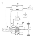
図1において、本実施形態に係るハイブリッド車両10は、エンジン200、第1のモータジェネレータMG1(以下、適宜「MG1」と略称する)、第2のモータジェネレータMG2(以下、適宜「MG2」と略称する)、駆動軸50、動力分割機構300、ロック機構400、PCU(PowerControlUnit)500、バッテリ600、減速機11、車軸12、車輪13、アクセル開度センサ14及びECU100を備えている。
In FIG. 1, a
エンジン200は、本発明に係る「内燃機関」の一例たるガソリンエンジンであり、ハイブリッド車両10の主たる動力源として機能するように構成されている。エンジン200の出力軸であるクランクシャフト210は、後述する動力分割機構300のキャリア304に連結されている。尚、本発明における「内燃機関」とは、例えば2サイクル又は4サイクルレシプロエンジン等を含み、少なくとも一の気筒を有し、当該気筒内部の燃焼室において、例えばガソリン、軽油或いはアルコール等の各種燃料を含む混合気が燃焼した際に発生する力を、例えばピストン、コネクティングロッド及びクランクシャフト等の物理的又は機械的な伝達手段を適宜介して動力として取り出すことが可能に構成された機関を包括する概念である。
The
第1のモータジェネレータMG1は、本発明に係る「発電機」の一例たる電動発電機であり、エンジン200からトルクの供給を受けてその回転軸が回転することにより、バッテリ600を充電するための、或いは第2のモータジェネレータMG2に電力を供給するための発電を主として行うことが可能に構成されている。
The first motor generator MG1 is a motor generator that is an example of a “generator” according to the present invention. The motor generator MG1 receives torque supplied from the
第2のモータジェネレータMG2は、本発明に係る「電動機」の一例たる電動発電機であり、エンジン200の動力を補助(即ち、アシスト)する電動機として、或いはバッテリ600を充電するための発電機として機能するように構成されている。より具体的には、第2のモータジェネレータMG2は、駆動力或いは制動力をアシストする装置であり、駆動力をアシストする場合には、第1のモータジェネレータMG1及びバッテリ600の少なくとも一方から電力が供給されて電動機として機能し、制動力をアシストする場合には、ハイブリッド車両10の車輪13側から伝達されるトルクによって回転させられて電力を発電する発電機として機能するように構成されている。第2のモータジェネレータMG2は、駆動軸50に対し動力を供給することが可能となるように、その回転軸が駆動軸50に連結されている。
The second motor generator MG2 is a motor generator that is an example of the “motor” according to the present invention, and serves as a motor that assists (that is, assists) the power of the
駆動軸50は、ハイブリッド車両10の車輪である車輪13に連結される車軸12に、デファレンシャル等の各種減速ギア装置を含む減速機構11を介して連結されている。
The
動力分割機構300は、プラネタリギア(遊星歯車機構)を含んでおり、エンジン200の動力を第1のモータジェネレータMG1の回転軸及び駆動軸50に分割或いは分配することが可能に構成されている。より具体的には、動力分割機構300は、外歯歯車のサンギア301と、サンギア301と同心円上に配置された内歯歯車のリングギア302と、サンギア301及びリングギア302に噛合するピニオンギア303と、ピニオンギア303を自転且つ公転自在に保持するキャリア304とを備えており、サンギア301、リングギア302及びキャリア304が3つの回転要素として相互に差動作用を生じるように構成されている。キャリア304には、エンジン200の出力軸であるクランクシャフト210が連結されている。サンギア301には、第1のモータジェネレータMG1の回転軸が連結されている。リングギア302には、駆動軸50が連結されている。動力分割機構300は、キャリア304から入力されるエンジン200からの動力を、サンギア301側(即ち、第1のモータジェネレータMG1側)とリングギア302側(即ち、駆動軸50側)とにそのギア比に応じて分配する。
Power split
ロック機構400は、本発明に係る「切り替え手段」の一例であり、第1のモータジェネレータMG1の回転軸を停止した状態で機械的に固定すること(即ち、第1のモータジェネレータMG1をロックすること)が可能に構成されている。と共に、ロック機構400は、第1のモータジェネレータMG1の回転軸を回転可能な状態で開放すること(即ち、第1のモータジェネレータMG1のロックを開放すること)が可能に構成されている。
The
詳細には、ロック機構400によって第1のモータジェネレータMG1がロックされた場合、エンジン200からの動力は、動力分割機構300によって第1のモータジェネレータMG1には分配されず、駆動軸50に出力されることになる。この際、典型的には、第2のモータジェネレータMG2は停止され、駆動軸50にはエンジン200からの駆動力のみが伝達される(即ち、ハイブリッド車両10は、エンジン200から出力される駆動力のみで走行することになる)。より詳細には、例えば、要求駆動力あるいはエンジンの負荷が小さい場合には、ロック機構400によって第1のモータジェネレータMG1の回転が阻止されて、動力分配機構300の実質的な変速比に設定されてよい。即ち、エンジンの回転数が可及的に低回転数に抑制される。その場合、動力分配機構300では、第1モータジェネレータMG1による発電は行われず、また第1モータジェネレータMG1が電動機として機能することもない。従って、第2モータジェネレータMG2で発電して第1モータジェネレータMG1に給電したり、或いはバッテリーから第1モータジェネレータMG1に給電する必要がないので、電力の消費が生じない。即ち、このようにして設定されるロック状態では動力の循環が生じず、動力損失やそれに伴う燃費の悪化を防止若しくは抑制することができる。尚、ロック機構は、後述されるように、例えばカム型の機構、ドッキング機構、くし形状機構、ATなどいずれの方式の機構でよい。
Specifically, when the first motor generator MG1 is locked by the
PCU500は、バッテリ600から取り出した直流電力を交流電流に変換して第1のモータジェネレータMG1及び第2のモータジェネレータMG2に供給すると共に、第1のモータジェネレータMG1及び第2のモータジェネレータMG2によって発電された交流電力を直流電力に変換してバッテリ600に供給することが可能に構成されたインバータ等を含み、バッテリ600と各モータジェネレータとの間の電力の入出力を個別に制御することが可能に構成された制御ユニットである。PCU500は、ECU100と電気的に接続されており、ECU100によってその動作が制御される構成となっている。
The
バッテリ600は、第1のモータジェネレータMG1及び第2のモータジェネレータMG2に電力を供給する電力供給源として機能することが可能に構成された充電可能な蓄電池である。
The
アクセル開度センサ14は、ハイブリッド車両10のアクセルペダル(不図示)の操作量たるアクセル開度を検出することが可能に構成されたセンサである。アクセル開度センサ14は、ECU100と電気的に接続されており、検出されたアクセル開度は、ECU100によって一定又は不定の周期で把握される構成となっている。
The
ECU100は、CPU(CentralProcessingUnit)、ROM(ReadOnlyMemory)及びRAM(RandomAccessMemory)等を備え、ハイブリッド車両10の動作全体を制御することが可能に構成された電子制御ユニットであり、本発明に係る「ハイブリッド車両の駆動制御装置」の一例である。ECU100は、CPU(CentralProcessingUnit)、ROM(ReadOnlyMemory)及びRAM(RandomAccessMemory)等を備え、エンジン200の動作全体を制御することが可能に構成された電子制御ユニットである。
The
制御部110は、ECU100の一部を構成し、アクセル開度センサ14によって検出されたアクセル開度に応じて定められる目標駆動トルク及び駆動軸50の回転数である駆動軸回転数(即ち、駆動軸回転速度)に応じて、ロック機構400を制御することが可能に構成されている。加えて、制御部110は、この目標駆動トルク及びこの駆動軸回転速度に加えて、エンジンの回転速度、第1のモータジェネレータMG1の回転速度及び第2のモータジェネレータMG2の回転速度に応じて、ロック機構400を制御することが可能に構成されている。尚、制御部110を含むECU100によるロック機構400の制御については、後に図6を参照して詳細に説明する。
The
(ロック機構に供給する潤滑油の供給システムの基本構成)
次に、図2を参照して、本実施形態に係るロック機構に供給する潤滑油の供給システムの基本構成について説明する。ここに、図2は、本実施形態に係るロック機構に供給する潤滑油の供給システムの基本構成を図式的に示したブロック図である。(Basic configuration of the supply system for the lubricating oil supplied to the lock mechanism)
Next, with reference to FIG. 2, a basic configuration of a supply system for lubricating oil supplied to the lock mechanism according to the present embodiment will be described. FIG. 2 is a block diagram schematically showing a basic configuration of a supply system for lubricating oil supplied to the lock mechanism according to the present embodiment.
図2に示されるように、本実施形態に係るロック機構に供給する潤滑油の供給システムは、大別すると、潤滑油(以下、適宜、オイルと称す)を潤滑させる潤滑系1000と、内燃機関の動力によってオイルの油圧を変化可能な機構式ポンプ系2000と、ロック機構400を含む冷却潤滑系40と、内燃機関の動力に依存しない電動力によってオイルの油圧を変化可能な電動式ポンプ系3000とを備えて構成されている。
As shown in FIG. 2, the supply system of the lubricating oil supplied to the lock mechanism according to the present embodiment is roughly divided into a
潤滑系1000は、オイルパン1010、メインオイルライン1020、シリンダヘッド1030、吸気用カムジャーナル1040、排気用カムジャーナル1050、チェーンテンショナ1060、オイルジェット1070、チェーン1080、クランクジャーナル1090、クランクピン1100、コンロッドオイルジェット1110、及び、ピストン1120を備えて構成されている。これらの潤滑系1000を構成する構成要素については、周知の要素を使用できるので、各要素の説明は省略する。
The
機構式ポンプ系2000は、オイルストレーナ201、機構式オイルポンプ202、圧力調整弁202a、サブオイルホール203、オイルフィルタ204、及び、圧力調整弁204aを備えて構成されている。
The
機構式オイルポンプ202は、潤滑系1000における潤滑油の循環に加えて、ロック機構400を潤滑及び冷却する潤滑油をオイル制御弁41に供給させる。これにより、ロック機構400を潤滑及び冷却することができる。特に、圧力調整弁202aは、機構式ポンプ202の流出側及び流入側の圧力を調整する。また、圧力調整弁204aは、オイルフィルタ204の流出側及び流入側の圧力を調整する。
The
冷却潤滑系40は、ロック機構400、オイル制御弁41、制御弁42、及び、制御弁43を備えて構成されている。
The
オイル制御弁41は、弁特性を変更するために供給された潤滑油の貯留空間を変更する。典型的には、オイル制御弁41はロック機構400を潤滑及び冷却するための油圧バルブである。
The oil control valve 41 changes the storage space for the lubricating oil supplied to change the valve characteristics. Typically, the oil control valve 41 is a hydraulic valve for lubricating and cooling the
制御弁42は、開弁された場合、機構式ポンプ系2000によってメインオイルライン102及びシリンダヘッド103を介して潤滑油をオイル制御弁41に供給する。他方で、閉弁された場合、潤滑油をオイル制御弁41に供給しない。
When the control valve 42 is opened, the
制御弁43は、開弁された場合、後述の電動式ポンプ系3000によって潤滑油をオイル制御弁41に供給する。他方で、閉弁された場合、潤滑油をオイル制御弁41に供給しない。
When the control valve 43 is opened, lubricating oil is supplied to the oil control valve 41 by an
電動式ポンプ系3000は、電動式オイルポンプ301、及び、オイルストレーナ302を備えて構成されている。電動式オイルポンプ401は、例えば内燃機関の始動時に、ロック機構400を潤滑及び冷却させる潤滑油をオイル制御弁41に供給させる。
The
この電動式オイルポンプ301は、機構式オイルポンプ202と比較して、内燃機関の機関回転数に影響されないので、ロック機構400を潤滑及び冷却するための潤滑油をより高精度且つ安定的にオイル制御弁41に供給することができる。
Since this
制御部110は、オイル制御弁41によってロック機構400を潤滑及び冷却するための潤滑油の供給量(或いは循環量)又は供給時間(或いは循環時間)を変化させることによって、ロック機構400内の、例えばドッキングクラッチ等の係合手段の近傍に存在する異物を除去する。
The
(ロック機構の動作)
ここで、図3及び図4を参照して、MG1ロックの誤開放が発生した場合を含むMG1のロック機構の動作について説明する。尚、本実施形態では、例えば電磁カム方式によるロック機構について説明したが、本発明は、例えばくし形状の噛み合いドッキング装置に適用してよい。或いは、本発明は、例えば摩擦力を利用した摩擦式クラッチ装置に適用してよい。或いは、本発明は、例えば湿式多板を利用したクラッチ装置等の他の方式のクラッチ装置に適用してよい。(Operation of lock mechanism)
Here, with reference to FIG. 3 and FIG. 4, the operation of the lock mechanism of MG1 including the case where the erroneous release of MG1 lock occurs will be described. In the present embodiment, for example, an electromagnetic cam type locking mechanism has been described. However, the present invention may be applied to, for example, a comb-shaped meshing docking device. Alternatively, the present invention may be applied to, for example, a friction clutch device using a frictional force. Alternatively, the present invention may be applied to other types of clutch devices such as a clutch device using a wet multi-plate.
ここに、図3は、本実施形態に係るMG1ロック機構における、外観を図式的に示した外観平面図である。図4は、本実施形態に係るMG1ロック機構における、MG1ロックの開放時の一の断面を図式的に示した断面図(図4(a))及びMG1ロックの実施時一の断面を図式的に示した断面図(図4(b))である。尚、図4(a)及び図4(b)の断面図は、図3中の線分A−A’を断面として、矢印Xから見た断面図である。 FIG. 3 is an external plan view schematically showing the external appearance of the MG1 locking mechanism according to the present embodiment. FIG. 4 is a cross-sectional view (FIG. 4A) schematically showing one cross-section when the MG1 lock is released in the MG1 lock mechanism according to the present embodiment, and a schematic cross-section when the MG1 lock is implemented. It is sectional drawing shown in (FIG.4 (b)). Note that the cross-sectional views of FIGS. 4A and 4B are cross-sectional views taken from the arrow X, with the line segment A-A ′ in FIG.
(ロック機構の基本構成)
図3、図4(a)及び図4(b)に示されるように、MG1のロック機構400は、部材401と、部材402と、ボール420と、ケース450とを備えて構成されている。特に、図4(a)或いは図4(b)中の、例えば隙間SPなどに存在する黒塗り星型及び黒塗りの五角形は夫々、ロック機構400内の潤滑油に含まれている異物を概念的に示している。(Basic structure of the lock mechanism)
As shown in FIGS. 3, 4 (a), and 4 (b), the
部材401は、MG1と平面401aを介して固定されており、MG1と共に回転可能である。
The
部材402は、例えば電磁力等によって、MG1の側からハイブリッド車両に静止状態で固定されているケース450の摩擦面450aの側へ向かう付勢力を受ける(図4(a)及び図4(b)中の右側から左側へ向かう方向を参照)。これにより、部材402は、MG1の側からケース450の摩擦面450aに向かって移動し、摩擦面450aに接触することにより、摩擦面450aに吸着される。これにより、ロック機構400内のカム機構を回転させ、MG1の回転軸に対して固定トルクを発生させる。これにより、MG1の回転軸を停止した状態で固定可能である。
The
ボール420は、球状の剛体であり部材401と部材402との間に配置され、部材401及び部材402に付勢力を与えることが可能である。
The
(ロック機構の開放状態)
図4(a)に示されるように、MG1ロックが開放されている場合、ロック機構400において、部材402と、ハイブリッド車両に静止状態で固定されているケース450との間には隙間SPがあり、ボール420及び部材402は、部材401と同様にして、MG1と共に回転している。尚、図4(a)中の矢印は、部材401、部材402及びMG1の回転方向を示している。(Lock mechanism opened)
As shown in FIG. 4A, when the MG1 lock is released, in the
即ち、ロック機構400において、部材402がケース450に係合しなく、それに伴い部材401及びボール420も係合しない非係合状態になることにより、MG1の回転軸が回転可能な回転可能状態或いは開放状態(即ち本発明に係る「第1状態」の一例)が形成されている。
That is, in the
(ロック機構の係合状態)
図4(b)に示されるように、MG1ロックが実施されている場合、部材402は、MG1側からケース450に向かう方向へ第1の付勢力F1を受け、ケース450の摩擦面450aに接触した際に生じる摩擦力により吸着状態となって固定されている。尚、第1の付勢力F1は、典型的には、MG1をロックするための駆動電流がケース450側で流れることによって磁性の性質を有する部材402に対して発生する電磁力であってよい。(Lock mechanism engaged state)
As shown in FIG. 4B, when the MG1 lock is performed, the
部材402は、この第1の付勢力F1に加えて、部材401からボール420を介して、部材402をケース450側に押し付けることにより生じる機構的な力である第2の付勢力F2を受け、ケース450の摩擦面450aに接した際に生じる摩擦力により吸着状態となって固定されている。これにより、ボール420及び部材402は、部材401の回転を停止させると共に、MG1の回転を停止させることによって、MG1ロックが正常に実施されている。
In addition to the first urging force F1, the
即ち、ロック機構400において、部材402がケース450の摩擦面450aに接触し摩擦力により停止し、それに伴い、ボール420を介して部材401の動作が停止し、これにより、部材401、部材402及びボール420がケース450に係合した係合状態になる。即ち、ロック機構400において、部材401、部材402及びボール420がケース450に係合した係合状態によって、MG1の回転軸が停止した固定状態或いは係合状態(即ち、本発明に係る「第2状態」の一例)が形成されている。このように、部材401、部材402及びボール420によって、本発明に係る「係合手段」の一例が構成されている。ケース450によって、本発明に係る「ハイブリッド車両の一部」の一例が構成されている。
That is, in the
特に、ロック機構400は、このような部材401、部材402及びボール420を備え、電磁力である第1の付勢力F1に加えて、上述の機構的な力である第2の付勢力F2を発生させる構成をとることにより、MG1を、部材401、部材402及びボール420を介して、ケース450の摩擦面450aに押し付けるための付勢力を、効率的且つ簡便に大きくさせることが可能である。これにより、第1の付勢力F1によってのみMG1をロックする場合と比較して、MG1の回転軸を停止した状態で固定するための固定トルクを、効率的且つ簡便に大きくさせることが可能である。
In particular, the
即ち、ECU100の制御下で、上述したMG1ロックが開放されている状態と、上述したMG1ロックが実施されている状態との切り替えである異物除去処理が行われることにより、部材401、部材402、ボール420、及び、ケース450の内壁の間に存在する異物を除去することができる。異物除去処理を行うタイミング等の異物除去処理の詳細については、後述される。
That is, under the control of the
(運転領域)
次に、図5を参照して、本実施形態に係るハイブリッド車両の運転領域について説明する。ここに、図5は、本実施形態に係るハイブリッド車両における、目標駆動トルク及び駆動軸回転数によって規定される運転領域を示すマップである。図5では、横軸に駆動軸回転数(即ち、駆動軸回転速度)を示し、縦軸に目標駆動トルク(即ち、駆動軸の目標駆動トルク)を示している。また、EV(ElectricVehicle)走行が行われる運転領域を「EV走行」として示し、電気CVT(Continuously Variable Transmission)走行が行われる運転領域を「電気CVT走行」として示し、第1のモータジェネレータMG1がロックされる運転領域を「MG1ロック走行」として示している。また、図5に示すマップは、エンジン200が定常燃焼状態にある場合に出力すると予め推定された出力トルクに基づいて予め作成されている。(Operating area)
Next, with reference to FIG. 5, the driving | running | working area | region of the hybrid vehicle which concerns on this embodiment is demonstrated. FIG. 5 is a map showing an operation region defined by the target drive torque and the drive shaft speed in the hybrid vehicle according to the present embodiment. In FIG. 5, the horizontal axis indicates the drive shaft rotation speed (that is, the drive shaft rotation speed), and the vertical axis indicates the target drive torque (that is, the target drive torque of the drive shaft). Further, an operation region where EV (Electric Vehicle) travel is performed is indicated as “EV travel”, an operation region where electric CVT (Continuously Variable Transmission) travel is performed is denoted as “electric CVT travel”, and the first motor generator MG1 is locked. The operation range to be performed is indicated as “MG1 lock travel”. Further, the map shown in FIG. 5 is created in advance based on output torque estimated in advance to be output when the
ECU100は、図5に示すマップ上において、目標駆動トルク及び駆動軸回転数によって定まる点(以下、「運転動作点」と称する)が、どの位置にくるかによって、運転モードを「EV走行モード」、「電気CVT走行モード」及び「MG1ロック走行」のいずれにするかを決定する。尚、本実施形態では、目標駆動トルク及び駆動軸回転数によって定まる運転動作点に加えて又は代えて、エンジンの出力トルク及び駆動軸回転数によって定まる動作点の座標上の位置に基づいて、運転モードを「EV走行モード」、「電気CVT走行モード」及び「MG1ロック走行」のいずれにするかを決定してよい。
The
具体的には、ECU100は、運転動作点が、図5に示すマップ上において、「EV走行」にあると判定した場合には、運転モードを「EV走行モード」に設定し、「電気CVT走行」にあると判定した場合には、運転モードを「電気CVTモード」に設定し、「MG1ロック走行」にあると判定した場合には、運転モードを「MG1ロックモード」に設定する。
Specifically, when the
ECU100は、運転モードを「EV走行モード」に設定した場合には、ハイブリッド車両10が、第2のモータジェネレータMG2からの駆動力のみで走行するEV走行を行うように、エンジン200、ロック機構400及びPCU500を制御する。
When the operation mode is set to “EV travel mode”,
ECU100は、運転モードを「電気CVT走行モード」に設定した場合には、ハイブリッド車両10が、エンジン200から動力分割機構300を介して駆動軸50に出力される駆動力と第2のモータジェネレータMG2から駆動軸50に出力される駆動力とで走行する電気CVT走行を行うように、エンジン200、ロック機構400及びPCU500を制御する。具体的には、ECU100は、運転モードを「電気CVT走行モード」に設定した場合には、エンジン200からの動力が第1のモータジェネレータMG1及び駆動軸50に分配されて、第1のモータジェネレータMG1で発電が行われると共に第2のモータジェネレータMG2からの駆動力が駆動軸50に出力されるように、エンジン200、ロック機構400及びPCU500を制御する。
When the operation mode is set to the “electric CVT travel mode”,
ECU100は、運転モードを「MG1ロックモード」に設定した場合には、ハイブリッド車両10が、エンジン200からの駆動力のみで走行するように、エンジン200、ロック機構400及びPCU500を制御する。具体的には、ECU100は、運転モードを「MG1ロックモード」に設定した場合には、第1のモータジェネレータMG1がロックされるように、ロック機構400を制御する。運転モードが「MG1ロックモード」である場合、後述されるように、伝達効率及び燃費効率を向上させることが可能である。
When the operation mode is set to “MG1 lock mode”,
尚、ECU100は、運転モードを「EV走行モード」又は「電気CVT走行モード」に設定した場合には、第1のモータジェネレータMG1がロックされないように、ロック機構400を制御する。
The
(動作原理)
次に、図6乃至図8を参照して、本発明の本実施形態に係るハイブリッド車両の駆動制御装置における動作原理について説明する。ここに、図6は、本実施形態に係るハイブリッド車両の駆動制御装置を統括制御するECUにおける、異物除去処理を含む制御処理の流れを示したフローチャートである。尚、図6で示された制御処理は、ECU100によって、所定周期で繰り返し実行される。図7は、本実施形態に係るハイブリッド車両の駆動制御装置を統括制御するECUにおける制御処理におけるエンジンの始動要求フラグ、MG1ロックの駆動電流、エンジンの始動要求フラグ、及びMG1の回転速度の時間軸上の変化を示したグラフ群(図7(a)、図7(b)、図7(c)及び図7(d))である。図8は、本実施形態に係る異物除去処理を行う際のハイブリッド車両の共線図の一例である。尚、図8中の縦軸が各回転軸の回転数を示し、横軸は、各ギヤのギヤ比を距離的な関係で示している。(Operating principle)
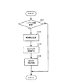
Next, with reference to FIGS. 6 to 8, the operation principle of the drive control apparatus for a hybrid vehicle according to the present embodiment of the present invention will be described. FIG. 6 is a flowchart showing a flow of control processing including foreign matter removal processing in the ECU that performs overall control of the hybrid vehicle drive control device according to the present embodiment. The control process shown in FIG. 6 is repeatedly executed by the
図6に示されるように、ECU100の制御下で、エンジンの始動が要求されているか否かが判定される(ステップS101)。具体的には、エンジンの始動が要求される場合、図7(a)に示されるように、時刻T1で、例えばドライバーによって、エンジンの始動が要求され、ECU100の制御下で、エンジン始動要求フラグが「Off」から「On」へと変化される。
As shown in FIG. 6, it is determined whether engine start is requested under the control of ECU 100 (step S <b> 101). Specifically, when engine start is requested, as shown in FIG. 7A, at time T1, for example, a driver requests engine start, and an engine start request flag is controlled under the control of the
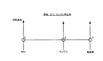
このステップS101の判定の結果、エンジンの始動が要求されていると判定される場合(ステップS101:Yes)、ECU100の制御下で、上述したMG1ロックが開放されている状態と、上述したMG1ロックが実施されている状態との切り替えである異物除去処理が行われる(ステップS102)。具体的には、図7(b)に示されるように、ECUの制御下で、時刻T1の後の所定期間において、MG1をロックするための駆動電流の「On」と「Off」が複数回繰り返されることにより異物除去処理が行われる。ここに、本実施形態に係る所定期間とは、MG1ロックが開放状態であって、且つ、MG1が回転を停止した停止状態である期間を意味する。具体的には、図8の共線図に示されるように、ハイブリッド車両において、MG1の回転数がゼロであり、且つ、エンジンの回転数がゼロであり、且つ、駆動軸の回転数がゼロである状態にある期間を意味する。
As a result of the determination in step S101, when it is determined that engine start is requested (step S101: Yes), the state in which the above-described MG1 lock is released under the control of the
より具体的には、図7(b)に示されるように、時刻T1の後の所定期間おいて、MG1をロックするための駆動電流の印加状態が「Off」から「On」へ変化されると共に、駆動電流の印加状態が「On」から「Off」へ変化されることにより、ロック機構400の開放状態と、係合状態と、開放状態との切り替えCH1が行われる。概ね同様にして、最初の切り替えCH1の後、駆動電流の印加状態が「Off」から「On」へ変化されると共に、駆動電流の印加状態が「On」から「Off」へ変化されることにより、ロック機構400の開放状態と、係合状態と、開放状態との切り替えCH2が行われる。概ね同様にして、2回目の切り替えCH2の後、駆動電流の印加状態が「Off」から「On」へ変化されると共に、駆動電流の印加状態が「On」から「Off」へ変化されることにより、ロック機構400の開放状態と、係合状態と、開放状態との切り替えCH3が行われる。尚、この所定期間において、ロック機構400の開放状態と、係合状態と、開放状態との切り替えは、単位時間当たり所定回数だけ行ってよい。この単位時間当たり所定回数は、典型的には、(i)ロック機構の部材401、部材402及びボール420(上述した図4(a)及び図4(b)等を参照)の重さ、(ii)ロック機構の開放状態から係合状態へと状態変化する際或いはロック機構の係合状態から開放状態へと状態変化する際のロック機構の機構的若しくは機械的な弾性係数、又は(iii)これらのロック機構の部材401、部材402及びボール420の重さ並びにロック機構の機構的若しくは機械的な弾性係数に基づいた共振周波数であってよい。
More specifically, as shown in FIG. 7B, in a predetermined period after time T1, the application state of the drive current for locking MG1 is changed from “Off” to “On”. At the same time, when the drive current application state is changed from “On” to “Off”, the
この結果、切り替えの故障原因となる異物をより効果的に除去することが可能であり、MG1ロックの切り替えの際、故障が発生することをより効果的に防止可能である。 As a result, it is possible to more effectively remove foreign substances that cause the switching failure, and it is possible to more effectively prevent the occurrence of a failure when switching the MG1 lock.
次に、ECU100の制御下で、エンジンの始動が許可される(ステップS103)。具体的には、図7(c)に示されるように、ECUの制御下で、異物除去処理の完了後、時刻T2で、エンジン始動許可フラグが「Off」から「On」へと変化される。 Next, engine start is permitted under the control of the ECU 100 (step S103). Specifically, as shown in FIG. 7C, under the control of the ECU, after completion of the foreign substance removal process, the engine start permission flag is changed from “Off” to “On” at time T2. .
次に、ECU100の制御下で、MG1の回転速度の制御が行われる(ステップS104)。具体的には、図7(d)に示されるように、ECUの制御下で、時刻T1の後、例えば「EV走行モード」又は「電気CVT走行モード」等の運転モードに応じて、MG1の回転速度が制御される。
Next, under the control of the
特に、発電機の回転軸が回転し始めた時点P1を含む期間において、ロック機構400の開放状態と、係合状態と、開放状態との切り替えを行ってよい。これにより、物理的な作用として、MG1の回転軸が回転し始めた時点に発生するMG1の遠心力又はMG1で発生する振動を、異物に対して及ぼすことが可能である。この結果、異物をロック機構の可動部から除去し、この異物の影響をより効果的に低減させ、ロック機構400の切り替えの際、故障が発生することをより効果的に防止可能である。
In particular, the
他方、上述したステップS101の判定の結果、ステップS101の判定の結果、エンジンの始動が要求されていると判定されない場合(ステップS101:No)、ECU100の制御下で、本実施形態に係る異物除去処理を含む制御処理は、一旦終了する。
On the other hand, as a result of the determination in step S101 described above, as a result of the determination in step S101, it is not determined that the engine is requested to start (step S101: No), the foreign object removal according to the present embodiment is controlled under the control of the
このように、本実施形態では、制御部110を含むECU100の制御下で、MG1の回転軸が回転していない所定期間に、ロック機構400の開放状態とロック機構400の係合状態との切り替えを行い、ロック機構400内に存在する異物に対して物理的な力を及ぼし、この異物を部材401、部材402、ボール420及びケース450の摩擦面450a(上述した図4(a)及び図4(b)を参照)から除去する。これにより、ロック機構400の開放状態と係合状態との切り替えの際の故障原因となるロック機構400内の異物の影響を効果的に低減させ、MG1ロックの実施とMG1ロックの開放との切り替えの際、故障が発生することを効果的に防止可能である。
As described above, in the present embodiment, switching between the unlocked state of the
これにより、MG1ロックの実施とMG1ロックの開放との切り替え故障の発生を殆ど又は完全に防止しつつ、MG1の回転軸が回転可能なMG1ロックが開放された状態と、MG1の回転軸が停止した状態で固定されるMG1ロックが実施された状態とを切り替えることが可能であり、ハイブリッド車両の駆動制御装置における伝達効率及び燃費効率を顕著に向上させることができる。 As a result, the state in which the MG1 lock capable of rotating the MG1 rotation shaft is released and the MG1 rotation shaft is stopped while almost or completely preventing the occurrence of a switching failure between the MG1 lock implementation and the MG1 lock release. It is possible to switch between the state in which the MG1 lock fixed in the performed state is performed, and the transmission efficiency and fuel efficiency in the hybrid vehicle drive control device can be significantly improved.
(オイル制御弁によるオイルの循環)
特に、本実施形態では、ECU100の制御下で、所定期間において、オイル制御弁41によって、オイルの循環量を増大させてよい。このことに加えて又は代えて、ECU100の制御下で、所定期間において、オイル制御弁41(図2を参照)によって、オイルの温度に応じて、オイル制御弁によってオイルを循環させる循環時間を変化させる。これにより、物理的な作用として、オイル制御弁41によって循環されるオイルによる粘性力を、増大されたオイルの循環量や循環時間に応じて、ロック機構400内の異物に対して効果的に及ぼすことが可能である。この結果、ロック機構400内において、異物をより効果的に除去し、MG1ロックの実施とMG1ロックの開放との切り替えの際、故障が発生することをより効果的に防止可能である。(Oil circulation by oil control valve)
In particular, in the present embodiment, the oil circulation amount may be increased by the oil control valve 41 during a predetermined period under the control of the
加えて、本実施形態では、ECU100の制御下で、所定期間において、ロック機構400の開放状態と、係合状態と、開放状態との切り替えを行う前に、オイル制御弁41によってロック機構内のオイルを全て循環させてよい。これにより、ロック機構内に存在する異物に対して物理的な力を及ぼし、この異物を係合手段から効果的に除去することが可能である。典型的には、ハイブリッド車両の駆動制御装置を、例えば数時間停止した後にオイル制御弁41によってオイルの循環を開始する場合、オイル循環の開始直後はオイルフィルタ204(図2を参照)に捕獲していた異物がオイル系統内を遊離している可能性が高い。このため、上述したMG1ロックの実施とMG1ロックの開放との切り替えによる異物除去を実施する前に、ロック機構内のオイルが全て入れ替わる程度、オイルを循環させ、オイルフィルタ204によって異物を捕捉することが望ましい。
In addition, in the present embodiment, under the control of the
(本実施形態に係る作用と効果との検討)
次に、図9を参照して、本実施形態に係る作用と効果について検討する。ここに、図9は、一般例に係る意図しないMG1ロックの開放(所謂、誤開放)が発生した場合のハイブリッド車両の共線図(図9(a))及び一般例に係る意図しないMG1ロック(所謂、誤係合)が発生した場合のハイブリッド車両の共線図(図9(b))である。(Examination of actions and effects according to this embodiment)
Next, with reference to FIG. 9, the operation and effect according to the present embodiment will be examined. FIG. 9 is an alignment chart (FIG. 9A) of the hybrid vehicle when an unintentional MG1 lock release (so-called erroneous release) according to the general example occurs and an unintended MG1 lock according to the general example. FIG. 9B is a collinear diagram (FIG. 9B) of the hybrid vehicle when (so-called erroneous engagement) occurs.
図9(a)に示されるように、ハイブリッド車両の走行中、MG1ロックの実施の最中に、意図しないMG1ロックの開放(所謂、MG1ロックの誤開放)が発生した場合、駆動軸での駆動力が抜けたように低下してしまうと共にMG1の回転数が急上昇してしまう。このMG1ロックの誤開放が検出される時点で、ECUの制御下で、MG1の回転速度制御が行われる。この際、瞬間的にはエンジンの回転数が上昇してしまうため、運転者に違和感を与えてしまう。このような運転者へ違和感を与えることを防止するために、MG1ロックの誤開放が発生した以降におけるMG1ロックを一律的に禁止する。このため、ハイブリッド車両において、MG1ロックによる伝達効率及び燃費効率の向上が妨げられる可能性があるという技術的な問題点が生じる。 As shown in FIG. 9 (a), when an unintentional MG1 lock release (so-called erroneous release of MG1 lock) occurs during the execution of the MG1 lock while the hybrid vehicle is running, As the driving force is lost, the driving force decreases and the rotational speed of MG1 increases rapidly. When the erroneous release of the MG1 lock is detected, the rotational speed control of the MG1 is performed under the control of the ECU. At this time, since the engine speed instantaneously increases, the driver feels uncomfortable. In order to prevent such a driver from feeling uncomfortable, the MG1 lock after the erroneous release of the MG1 lock is uniformly prohibited. For this reason, in the hybrid vehicle, there arises a technical problem that there is a possibility that improvement in transmission efficiency and fuel efficiency due to MG1 lock may be hindered.
MG1ロックの誤開放について、詳細には、ロック機構400において、機構的な原因又は物理的な原因により、部材402と、ケース450との間に隙間が生じて、MG1ロックの誤開放が発生してしまうのである。この機構的な原因としての、例えば路面からの反力が、駆動軸を介して、MG1の回転軸に伝達された、予想外の外部入力トルクにより、部材402と、ケース450との間に隙間が生じて、MG1ロックの誤開放が発生してしまうことが考えられる。或いは、この物理的な原因としての、部材402をケース450に向かって押し付けるように移動させる際に異物や凹凸部等の障害物に引っ掛かることにより、部材402と、ケース450との間に隙間が生じて、MG1ロックの誤開放が発生してしまうことが考えられる。
Regarding the erroneous release of the MG1 lock, in detail, in the
或いは、図9(b)に示されるように、ハイブリッド車両が、例えば「電気CVTモード」で走行中、意図しないMG1ロックの実施(所謂、MG1ロックの誤係合)が発生した場合、MG1の回転数が急降下してしまうと共に、瞬間的にエンジンの回転数が降下してしまうにも関わらず、駆動軸での駆動力は維持される。このため、駆動軸の半径方向に生じるせん断力が発生し、駆動軸が折れ曲がったり、せん断されてしまう可能性が生じ、ハイブリッド車両が物理的に破損してしまう可能性が生じる。 Alternatively, as shown in FIG. 9B, when an unintentional MG1 lock (so-called MG1 lock misengagement) occurs while the hybrid vehicle is running in, for example, the “electric CVT mode”, The driving force on the drive shaft is maintained despite the sudden decrease in the rotational speed and the instantaneous decrease in the rotational speed of the engine. For this reason, a shearing force generated in the radial direction of the drive shaft is generated, the drive shaft may be bent or sheared, and the hybrid vehicle may be physically damaged.
これに対して、本実施形態によれば、ECU100の制御下で、MG1の回転軸が回転していない所定期間に、ロック機構400の開放状態とロック機構400の係合状態との切り替えを行い、ロック機構400内に存在する異物に対して物理的な力を及ぼし、この異物をロック機構400から除去する。これにより、ロック機構400の開放状態と係合状態との切り替えの際の故障原因となるロック機構400内の異物の影響を効果的に低減させ、MG1ロックの実施とMG1ロックの開放との切り替えの際、故障が発生することを効果的に防止可能である。
On the other hand, according to the present embodiment, switching between the unlocked state of the
この結果、MG1ロックの実施とMG1ロックの開放との切り替え故障の発生を殆ど又は完全に防止しつつ、MG1の回転軸が回転可能なMG1ロックが開放された状態と、MG1の回転軸が停止した状態で固定されるMG1ロックが実施された状態とを切り替えることが可能であり、ハイブリッド車両の駆動制御装置における伝達効率及び燃費効率を顕著に向上させることができる。 As a result, the state in which the MG1 lock capable of rotating the MG1 rotation shaft is released and the MG1 rotation shaft is stopped while almost or completely preventing the occurrence of a switching failure between the MG1 lock implementation and the MG1 lock release. It is possible to switch between the state in which the MG1 lock fixed in the performed state is performed, and the transmission efficiency and fuel efficiency in the hybrid vehicle drive control device can be significantly improved.
(第2実施形態)
次に、図10及び図11を参照して、本発明の第2実施形態に係るハイブリッド車両の駆動制御装置における動作原理について説明する。ここに、図10は、第2実施形態に係るハイブリッド車両の駆動制御装置を統括制御するECUにおける、異物除去処理を含む制御処理の流れを示したフローチャートである。尚、図10で示された制御処理は、ECU100によって、所定周期で繰り返し実行される。また、図11は、第2実施形態に係る異物除去処理を行う所定期間におけるハイブリッド車両の共線図の一及び他の例(図11(a)及び図11(b))である。尚、図11(a)及び図11(b)中の縦軸が各回転軸の回転数を示し、横軸は、各ギヤのギヤ比を距離的な関係で示している。(Second Embodiment)
Next, with reference to FIG.10 and FIG.11, the operation principle in the drive control apparatus of the hybrid vehicle which concerns on 2nd Embodiment of this invention is demonstrated. FIG. 10 is a flowchart showing the flow of control processing including foreign matter removal processing in the ECU that performs overall control of the hybrid vehicle drive control device according to the second embodiment. The control process shown in FIG. 10 is repeatedly executed by the
図10に示されるように、ECU100の制御下で、上述したMG1ロックが実施されている状態との切り替えである異物除去処理を行う期間である所定期間であるか否かが判定される(ステップS201)。具体的には、図11(a)の共線図に示されるように、ハイブリッド車両が停車中であり、且つ、エンジンを始動する際のMG1によるクランキングが開始される時点を含む所定期間であるか否かが判定される。このような所定期間において、異物除去処理が行われることにより、物理的な作用として、MG1によって内燃機関を始動するクランキングを開始した時点に発生するMG1の遠心力又はMG1で発生する振動を、異物に対して及ぼすことが可能である。この結果、異物をロック機構内の係合部分から除去し、この異物の影響をより効果的に低減させ、MG1ロックの実施とMG1ロックの開放との切り替えの際、故障が発生することをより効果的に防止可能である。
As shown in FIG. 10, under the control of the
或いは、具体的には、図11(b)の共線図に示されるように、ハイブリッド車両が停車中の状態から、MG2によってEV走行が開始される時点を含む所定期間であるか否かが判定される。このような所定期間において、異物除去処理が行われることにより、物理的な作用として、MG2によってMG1が逆回転を開始した時点に発生するMG1の遠心力又はMG1で発生する振動を、異物に対して及ぼすことが可能である。この結果、異物をロック機構内の係合部分から除去し、この異物の影響をより効果的に低減させ、MG1ロックの実施とMG1ロックの開放との切り替えの際、故障が発生することをより効果的に防止可能である。 Or, specifically, as shown in the collinear diagram of FIG. 11B, whether or not the hybrid vehicle is in a predetermined period including a time point at which EV driving is started by the MG2 from the stopped state. Determined. By performing the foreign matter removal process in such a predetermined period, as a physical action, the centrifugal force of MG1 generated when MG1 starts reverse rotation by MG2 or the vibration generated by MG1 is applied to the foreign matter. Can be applied. As a result, the foreign matter is removed from the engagement portion in the lock mechanism, the influence of the foreign matter is more effectively reduced, and a failure occurs when switching between the MG1 lock implementation and the MG1 lock release. It can be effectively prevented.
本発明は、上述した実施形態に限られるものではなく、請求の範囲及び明細書全体から読み取れる発明の要旨或いは思想に反しない範囲で適宜変更可能であり、そのような変更を伴うハイブリッド車両の駆動制御装置及び方法もまた本発明の技術的範囲に含まれるものである。 The present invention is not limited to the above-described embodiments, and can be appropriately changed without departing from the gist or concept of the invention that can be read from the claims and the entire specification. Control devices and methods are also within the scope of the present invention.
本発明は、ハイブリッド車両の駆動制御装置及び方法に利用可能である。 The present invention is applicable to a drive control apparatus and method for a hybrid vehicle.
10…ハイブリッド車両、50…駆動軸、100…ECU、110…制御部、200…エンジン、300…動力分割機構、400…ロック機構、600…バッテリ、1000…潤滑系と、40…冷却潤滑系と、2000…機構式ポンプ系、3000…電動式ポンプ系、MG1…第1のモータジェネレータ、MG2…第2のモータジェネレタ。
DESCRIPTION OF
Claims (10)
前記内燃機関の動力により発電可能であると共に該発電により得られた電力を蓄電池に充電可能な発電機と、
前記内燃機関の動力を、駆動軸及び前記発電機の回転軸に分割する動力分割機構と、
前記発電機及び前記蓄電池の少なくとも一方から供給される電力に応じた動力を前記駆動軸に出力可能な電動機と、
前記発電機の回転軸が停止した状態で前記発電機を固定可能なロック機構と、
を備え、
前記ロック機構は、
前記発電機のロータに固定されると共に、前記ロータと一体回転可能な第1部材と、
前記第1部材の前記ロータ側とは反対側に対向して配置され、前記第1部材と係合可能な第2部材と、
前記第2部材の前記第1部材側とは反対側の面に対向する面を有し、電磁力を発生可能なケースと、
を有し、
前記ロック機構は、(i)前記第1部材、前記第2部材及び前記ケースが互いに係合しない非係合状態とされることにより、前記発電機の回転軸が回転可能な第1状態を実現可能であると共に、(ii)前記ケースに電磁力が発生することにより前記第1部材、前記第2部材及び前記ケースが互いに係合する係合状態とされることにより、前記発電機の回転軸が停止した状態で固定される第2状態を実現可能であり、
前記非係合状態から前記係合状態へと状態変化する係合動作及び前記係合状態から前記非係合状態へと状態変化する非係合動作により発生する熱を伝導可能であると共に、前記係合動作及び前記非係合動作を潤滑可能なオイルの前記ロック機構への循環を制御するオイル制御弁と、
前記発電機の回転軸が回転していない所定期間において、前記第1状態及び第2状態のうち一方の状態から前記第1状態及び前記第2状態のうち他方の状態へと切り替えた後、前記他方の状態から前記一方の状態へと切り替えるように前記ロック機構を制御すると共に、前記オイルが循環するように前記オイル制御弁を制御する制御手段と、
を更に備える
ことを特徴とするハイブリッド車両の駆動制御装置。An internal combustion engine;
A generator capable of generating power with the power of the internal combustion engine and charging a storage battery with the electric power obtained by the power generation;
A power split mechanism that splits the power of the internal combustion engine into a drive shaft and a rotary shaft of the generator;
An electric motor capable of outputting power corresponding to electric power supplied from at least one of the generator and the storage battery to the drive shaft;
A lock mechanism capable of fixing the generator with the rotating shaft of the generator stopped;
With
The locking mechanism is
A first member fixed to the rotor of the generator and rotatable integrally with the rotor;
A second member disposed opposite to the rotor side of the first member and engageable with the first member;
A case having a surface facing the surface of the second member opposite to the first member, and capable of generating electromagnetic force;
Have
The lock mechanism (i) realizes a first state in which the rotating shaft of the generator is rotatable by being in a disengaged state in which the first member, the second member, and the case are not engaged with each other. And (ii) when the electromagnetic force is generated in the case, the first member, the second member, and the case are brought into an engaged state so that the rotating shaft of the generator is engaged. A second state can be realized that is fixed in a stopped state,
The heat generated by the engagement operation that changes state from the non-engagement state to the engagement state and the non-engagement operation state change from the engagement state to the non-engagement state can be conducted, and An oil control valve that controls circulation of oil that can lubricate the engagement operation and the non-engagement operation to the lock mechanism;
In a predetermined period when the rotating shaft of the generator is not rotating, after switching from one state of the first state and the second state to the other state of the first state and the second state, Control means for controlling the lock mechanism so as to switch from the other state to the one state, and for controlling the oil control valve so that the oil circulates ;
A drive control apparatus for a hybrid vehicle , further comprising:
前記電動機として、第2電動発電機とを備え、
前記制御手段は、前記所定期間として、前記第1電動発電機又は前記第2電動発電機によって前記内燃機関を始動するクランキングを開始した時点を含む期間に、前記発電機の動作状態を前記一方の状態から前記他方の状態へと切り替えるように前記ロック機構を制御することを特徴とする請求項1に記載のハイブリッド車両の駆動制御装置。As the generator, a first motor generator,
As the electric motor, comprising a second motor generator,
The control means sets the operating state of the generator as the predetermined period during a period including a time point when cranking for starting the internal combustion engine by the first motor generator or the second motor generator is started. The drive control apparatus for a hybrid vehicle according to claim 1, wherein the lock mechanism is controlled to switch from the state to the other state.
前記電動機として、第2電動発電機とを備え、
前記制御手段は、前記所定期間として、前記第1電動発電機又は前記第2電動発電機によって電力に応じた動力を前記駆動軸に出力し始めた時点を含む期間に、前記発電機の動作状態を前記一方の状態から前記他方の状態へと切り替えるように前記ロック機構を制御することを特徴とする請求項1に記載のハイブリッド車両の駆動制御装置。As the generator, a first motor generator,
As the electric motor, comprising a second motor generator,
The control means includes an operating state of the generator in a period including a time point when the first motor generator or the second motor generator starts to output power corresponding to electric power to the drive shaft as the predetermined period. 2. The drive control apparatus for a hybrid vehicle according to claim 1, wherein the lock mechanism is controlled so as to switch from one state to the other state.
前記発電機の回転軸が回転していない所定期間において、前記第1状態及び第2状態のうち一方の状態から前記第1状態及び前記第2状態のうち他方の状態へと切り替えた後、前記他方の状態から前記一方の状態へと切り替えるように前記ロック機構を制御すると共に、前記オイルが循環するように前記オイル制御弁を制御する制御工程を備える
ことを特徴とするハイブリッド車両の駆動制御方法。An internal combustion engine, a generator capable of generating electric power by the power of the internal combustion engine and charging a storage battery with electric power obtained by the power generation, and dividing the power of the internal combustion engine into a drive shaft and a rotating shaft of the generator A power split mechanism, an electric motor capable of outputting power corresponding to electric power supplied from at least one of the generator and the storage battery to the drive shaft, and the generator in a state where the rotating shaft of the generator is stopped. A lock mechanism that can be fixed, and the lock mechanism is fixed to the rotor of the generator, and is capable of rotating integrally with the rotor, and a side of the first member opposite to the rotor side. A second member that can be engaged with the first member and a surface that faces the surface of the second member opposite to the first member, and can generate electromagnetic force. A case, and the locking mechanism (I) The first state in which the rotating shaft of the generator can rotate can be realized by disengaging the first member, the second member, and the case from each other. (Ii) A state in which the rotating shaft of the generator is stopped when the first member, the second member, and the case are engaged with each other when electromagnetic force is generated in the case. The second state can be realized, and the engagement operation changes from the non-engagement state to the engagement state and the non-engagement state changes from the engagement state to the non-engagement state. In a drive control device for a hybrid vehicle, further comprising an oil control valve capable of conducting heat generated by an operation and controlling circulation of oil to the lock mechanism capable of lubricating the engagement operation and the non-engagement operation Hybrid A drive control method for de vehicle,
In a predetermined period when the rotating shaft of the generator is not rotating, after switching from one state of the first state and the second state to the other state of the first state and the second state, It controls the locking mechanism to switch to the one state from the other states, and a control step of the oil to control the oil control valve so as to circulate
A drive control method for a hybrid vehicle.
Applications Claiming Priority (1)
| Application Number | Priority Date | Filing Date | Title |
|---|---|---|---|
| PCT/JP2009/059677 WO2010137129A1 (en) | 2009-05-27 | 2009-05-27 | Apparatus and method for controlling drive of hybrid vehicle |
Publications (2)
| Publication Number | Publication Date |
|---|---|
| JPWO2010137129A1 JPWO2010137129A1 (en) | 2012-11-12 |
| JP5093365B2 true JP5093365B2 (en) | 2012-12-12 |
Family
ID=43222270
Family Applications (1)
| Application Number | Title | Priority Date | Filing Date |
|---|---|---|---|
| JP2010546753A Expired - Fee Related JP5093365B2 (en) | 2009-05-27 | 2009-05-27 | Hybrid vehicle drive control apparatus and method |
Country Status (5)
| Country | Link |
|---|---|
| US (1) | US8452472B2 (en) |
| EP (1) | EP2439119B1 (en) |
| JP (1) | JP5093365B2 (en) |
| CN (1) | CN102143872B (en) |
| WO (1) | WO2010137129A1 (en) |
Families Citing this family (8)
| Publication number | Priority date | Publication date | Assignee | Title |
|---|---|---|---|---|
| CN102348586B (en) * | 2009-03-12 | 2014-07-16 | 丰田自动车株式会社 | Device for preventing false lock |
| WO2010137129A1 (en) * | 2009-05-27 | 2010-12-02 | トヨタ自動車株式会社 | Apparatus and method for controlling drive of hybrid vehicle |
| US8618752B2 (en) * | 2010-07-21 | 2013-12-31 | Superior Electron, Llc | System, architecture, and method for minimizing power consumption and increasing performance in electric vehicles |
| CN103338957A (en) * | 2011-01-27 | 2013-10-02 | 丰田自动车株式会社 | Vehicle, and vehicle control method |
| WO2013140544A1 (en) * | 2012-03-21 | 2013-09-26 | トヨタ自動車株式会社 | Drive control device for hybrid vehicle |
| JP5772782B2 (en) * | 2012-10-15 | 2015-09-02 | トヨタ自動車株式会社 | vehicle |
| JP6183333B2 (en) * | 2014-11-07 | 2017-08-23 | トヨタ自動車株式会社 | Hybrid car |
| CN109183587A (en) * | 2018-09-25 | 2019-01-11 | 昆明理工大学 | A kind of pavement cutting machine of hybrid power |
Citations (7)
| Publication number | Priority date | Publication date | Assignee | Title |
|---|---|---|---|---|
| JPH08322108A (en) * | 1995-05-25 | 1996-12-03 | Aqueous Res:Kk | Hybrid vehicle |
| JPH1044789A (en) * | 1996-08-05 | 1998-02-17 | Aqueous Res:Kk | Hybrid powered automobile |
| JP2001152888A (en) * | 1999-11-25 | 2001-06-05 | Denso Corp | Variable valve-timing control device of internal combustion engine |
| JP2001234768A (en) * | 2000-02-23 | 2001-08-31 | Denso Corp | Valve control device for internal combustion engine |
| JP2003002588A (en) * | 2001-06-20 | 2003-01-08 | Hitachi Constr Mach Co Ltd | Braking device for winch, and hoist gear for crane provided with the braking device |
| JP2006298132A (en) * | 2005-04-20 | 2006-11-02 | Nissan Motor Co Ltd | Brake control device |
| WO2010137129A1 (en) * | 2009-05-27 | 2010-12-02 | トヨタ自動車株式会社 | Apparatus and method for controlling drive of hybrid vehicle |
Family Cites Families (8)
| Publication number | Priority date | Publication date | Assignee | Title |
|---|---|---|---|---|
| US5823281A (en) * | 1995-05-25 | 1998-10-20 | Kabushikikaisha Equos Reseach | Hybrid vehicle |
| JP3951562B2 (en) * | 2000-06-28 | 2007-08-01 | アイシン・エィ・ダブリュ株式会社 | Hybrid type vehicle |
| JP2002051407A (en) | 2000-08-03 | 2002-02-15 | Toyota Motor Corp | Controller for power train |
| JP3815220B2 (en) * | 2000-12-27 | 2006-08-30 | アイシン・エィ・ダブリュ株式会社 | Hybrid vehicle and control method thereof |
| JP4236084B2 (en) * | 2002-08-09 | 2009-03-11 | アイシン・エィ・ダブリュ株式会社 | Hybrid vehicle drive control device, hybrid vehicle drive control method, and hybrid vehicle drive control program |
| JP3891146B2 (en) | 2003-05-22 | 2007-03-14 | トヨタ自動車株式会社 | Hybrid vehicle drive system |
| JP4023444B2 (en) * | 2003-12-24 | 2007-12-19 | トヨタ自動車株式会社 | Hybrid vehicle drive system |
| JP3783716B2 (en) * | 2004-01-22 | 2006-06-07 | トヨタ自動車株式会社 | Control device for hybrid vehicle |
-
2009
- 2009-05-27 WO PCT/JP2009/059677 patent/WO2010137129A1/en active Application Filing
- 2009-05-27 CN CN200980130498.0A patent/CN102143872B/en active Active
- 2009-05-27 JP JP2010546753A patent/JP5093365B2/en not_active Expired - Fee Related
- 2009-05-27 US US13/056,923 patent/US8452472B2/en active Active
- 2009-05-27 EP EP09845196.6A patent/EP2439119B1/en active Active
Patent Citations (7)
| Publication number | Priority date | Publication date | Assignee | Title |
|---|---|---|---|---|
| JPH08322108A (en) * | 1995-05-25 | 1996-12-03 | Aqueous Res:Kk | Hybrid vehicle |
| JPH1044789A (en) * | 1996-08-05 | 1998-02-17 | Aqueous Res:Kk | Hybrid powered automobile |
| JP2001152888A (en) * | 1999-11-25 | 2001-06-05 | Denso Corp | Variable valve-timing control device of internal combustion engine |
| JP2001234768A (en) * | 2000-02-23 | 2001-08-31 | Denso Corp | Valve control device for internal combustion engine |
| JP2003002588A (en) * | 2001-06-20 | 2003-01-08 | Hitachi Constr Mach Co Ltd | Braking device for winch, and hoist gear for crane provided with the braking device |
| JP2006298132A (en) * | 2005-04-20 | 2006-11-02 | Nissan Motor Co Ltd | Brake control device |
| WO2010137129A1 (en) * | 2009-05-27 | 2010-12-02 | トヨタ自動車株式会社 | Apparatus and method for controlling drive of hybrid vehicle |
Also Published As
| Publication number | Publication date |
|---|---|
| EP2439119A4 (en) | 2013-06-19 |
| WO2010137129A1 (en) | 2010-12-02 |
| EP2439119B1 (en) | 2014-09-03 |
| CN102143872B (en) | 2014-06-18 |
| US8452472B2 (en) | 2013-05-28 |
| CN102143872A (en) | 2011-08-03 |
| US20120059540A1 (en) | 2012-03-08 |
| JPWO2010137129A1 (en) | 2012-11-12 |
| EP2439119A1 (en) | 2012-04-11 |
Similar Documents
| Publication | Publication Date | Title |
|---|---|---|
| JP5093365B2 (en) | Hybrid vehicle drive control apparatus and method | |
| RU2480360C2 (en) | Automotive gearshift drive system and method of gear shifting | |
| US8469859B2 (en) | Control apparatus for hybrid vehicle | |
| KR101556488B1 (en) | Control device for vehicle | |
| KR101905060B1 (en) | Driving system for vehicle | |
| US9688132B2 (en) | Hybrid vehicle | |
| US20160167639A1 (en) | Control device for vehicle | |
| KR20150122065A (en) | Hybrid vehicle control apparatus | |
| US11173915B2 (en) | Hybrid vehicle drive apparatus | |
| CN111712391A (en) | Drive device for hybrid vehicle | |
| JP2009115186A (en) | Vehicle control device and hybrid vehicle mounted with the control device | |
| JP5527264B2 (en) | Control device for hybrid vehicle | |
| JP4586929B1 (en) | Control device for hybrid vehicle | |
| JP2012153230A (en) | Hybrid vehicle control device | |
| JP2012081793A (en) | Control device for hybrid vehicle | |
| JP2010143281A (en) | Control device for hybrid drive device | |
| JP5229088B2 (en) | Hybrid vehicle drive control apparatus and method | |
| JP2012081792A (en) | Hybrid vehicle control device | |
| JP2014213635A (en) | Control device for hybrid vehicle | |
| JP5510165B2 (en) | Control device for hybrid vehicle | |
| JP2011037322A (en) | Controller of hybrid vehicle | |
| JP2010269668A (en) | Hybrid vehicle controller | |
| JP2012056421A (en) | Hybrid vehicle control device | |
| JP5229089B2 (en) | Hybrid vehicle drive control apparatus and method | |
| JP2012056487A (en) | Hybrid vehicle control device |
Legal Events
| Date | Code | Title | Description |
|---|---|---|---|
| TRDD | Decision of grant or rejection written | ||
| A01 | Written decision to grant a patent or to grant a registration (utility model) |
Free format text: JAPANESE INTERMEDIATE CODE: A01 Effective date: 20120821 |
|
| A01 | Written decision to grant a patent or to grant a registration (utility model) |
Free format text: JAPANESE INTERMEDIATE CODE: A01 |
|
| A61 | First payment of annual fees (during grant procedure) |
Free format text: JAPANESE INTERMEDIATE CODE: A61 Effective date: 20120903 |
|
| R151 | Written notification of patent or utility model registration |
Ref document number: 5093365 Country of ref document: JP Free format text: JAPANESE INTERMEDIATE CODE: R151 |
|
| FPAY | Renewal fee payment (event date is renewal date of database) |
Free format text: PAYMENT UNTIL: 20150928 Year of fee payment: 3 |
|
| LAPS | Cancellation because of no payment of annual fees |