JP6182759B2 - Shutter device - Google Patents
Shutter device Download PDFInfo
- Publication number
- JP6182759B2 JP6182759B2 JP2013240297A JP2013240297A JP6182759B2 JP 6182759 B2 JP6182759 B2 JP 6182759B2 JP 2013240297 A JP2013240297 A JP 2013240297A JP 2013240297 A JP2013240297 A JP 2013240297A JP 6182759 B2 JP6182759 B2 JP 6182759B2
- Authority
- JP
- Japan
- Prior art keywords
- wing
- slat
- movable wing
- opening
- guide rail
- Prior art date
- Legal status (The legal status is an assumption and is not a legal conclusion. Google has not performed a legal analysis and makes no representation as to the accuracy of the status listed.)
- Active
Links
Images


Description
本発明は、建物の開口部に用いられていてスラットによって採光や通風等の可能なシャッター装置に関する。 The present invention relates to a shutter device that is used in an opening of a building and can be daylighted or ventilated by a slat.
従来、スラットをブラインドとして用いた採光や通風等の可能なシャッターカーテンとして、例えば特許文献1に記載されたシャッター装置が提案されている。
このシャッター装置は固定羽と可動羽が重ねて設けられたスラットが上下方向に複数連結されていて、シャッターカーテンが建物の開口部を閉鎖させた閉鎖状態で可動羽を開閉操作させることができる。
Conventionally, for example, a shutter device described in Patent Document 1 has been proposed as a shutter curtain capable of daylighting or ventilation using a slat as a blind.
In this shutter device, a plurality of slats each provided with a fixed wing and a movable wing are connected in the vertical direction, and the movable wing can be opened and closed in a closed state where the shutter curtain closes the opening of the building.
このシャッター装置は、上下方向に配列された複数のスラットにおいて上側の固定羽で下側のスラットに設けた可動羽を押すことで、下側の可動羽を回動させて開作動させ、固定羽の開口を通して採光や通風ができるようになっている。しかも、開状態にある可動羽によって外部から室内を視認しにくい状態にすることができる。 In this shutter device, a plurality of slats arranged in the vertical direction push the movable wing provided on the lower slat with the upper fixed wing, thereby rotating the lower movable wing to open the fixed wing. Lighting and ventilation can be made through the opening. In addition, the movable wing in the open state can make it difficult to visually recognize the room from the outside.
上述したシャッター装置では、上側のスラットと下側のスラットとの連結部や各スラットにおける固定羽に対する可動羽の連結部には、両端部に固定部材が設置され、上側のスラットに対して下側のスラットが横ずれたり、各スラットの固定羽に対して可動羽が横ずれしたりすることを防いでいる。 In the shutter device described above, the connecting portion between the upper slat and the lower slat and the connecting portion of the movable wing with respect to the fixed wing in each slat are provided with fixing members at both ends, and lower than the upper slat. The slats of the slats are prevented from being laterally displaced, and the movable wings are not laterally displaced relative to the fixed wings of each slat.
また、特許文献2に記載されたシャッター装置では、スラット端部を収納したガイドレール部に設けたリンク機構でスラットの開閉作動等を安定させて行っている。そして、リンク機構を動かすことでスラットの開き角度を調整するので各スラットの細かな開閉動作を制御することができる。
Further, in the shutter device described in
しかしながら、特許文献2に記載されたシャッター装置では、リンク機構をスラットごとに連動させる構成であるために、スラットごとにリンクやその駆動機構等の多数の専用部品が必要になり、部品点数が非常に多くなるという欠点があった。
However, since the shutter device described in
本発明は、このような課題に鑑みてなされたものであって、スラットの開閉作動を少ない部品で簡単な機構を用いて制御できるようにしたシャッター装置を提供することを目的とする。 The present invention has been made in view of such problems, and an object of the present invention is to provide a shutter device that can control the opening / closing operation of a slat using a simple mechanism with few parts.
本発明によるシャッター装置は、開口を設けた固定羽と開口を開閉可能な可動羽とを備えたスラットが上下方向に複数連結されていて、上下のスラットの相対移動によって可動羽を開作動させるようにしたシャッター装置であって、スラットの端部の上下動をガイドする受け入れ部を有するガイドレール部と、ガイドレール部の受け入れ部内に対向して設けられていて可動羽の端部に形成した支持部に当接可能な抵抗体とを備え、少なくともいずれか一方の抵抗体は、一部の抵抗体が他の抵抗体より接触抵抗が大きいものを混在させたことを特徴とする。
本発明によるシャッター装置によれば、スラットの可動羽が開作動した状態でその端部に形成した支持部がガイドレール部の受け入れ部内に対向して設けた抵抗体に当接して開状態にある可動羽を支持でき、特に一部の抵抗体の接触抵抗が大きいので開状態にある可動羽の支持部の開閉作動に抵抗して安定して保持できる。また、抵抗体として接触抵抗の大きい一部の抵抗体と接触抵抗の小さい他の抵抗体とを混在させたことで、簡単な構成で確実に可動羽を開状態に保持できると共に、閉状態では抵抗体に当接しないか当接が少ないために容易に上下動できる。
In the shutter device according to the present invention, a plurality of slats each including a fixed wing provided with an opening and a movable wing capable of opening and closing the opening are connected in the vertical direction, and the movable wing is opened by relative movement of the upper and lower slats. A guide rail portion having a receiving portion for guiding the vertical movement of the end portion of the slat, and a support formed in the receiving portion of the guide rail portion so as to be opposed to the end portion of the movable wing. And at least one of the resistors is characterized in that some of the resistors have a larger contact resistance than the other resistors.
According to the shutter device of the present invention, when the movable wing of the slat is opened, the support portion formed at the end of the slat is in the open state in contact with the resistor provided facing the receiving portion of the guide rail portion. The movable wing can be supported, and in particular, the contact resistance of some of the resistors is large, so that it can be stably held by resisting the opening / closing operation of the support portion of the movable wing in the open state. In addition, by mixing some resistors with high contact resistance and other resistors with low contact resistance as resistors, the movable wings can be reliably held in an open state with a simple configuration, and in the closed state It can easily move up and down because it does not contact the resistor or has little contact.
また、抵抗体は複数の繊維からなる繊維体であることが好ましい。
抵抗体が複数の繊維からなることで、可動羽の支持部が開閉作動する際に、繊維が個別に変位して作動時の抵抗が比較的小さく、しかも開状態にある可動羽と繊維体との当接による抵抗が接触抵抗の大きい一部の抵抗体によって大きく設定される。
Moreover, it is preferable that a resistor is a fiber body which consists of a some fiber.
Since the resistor is composed of a plurality of fibers, when the support portion of the movable wing is opened and closed, the fibers are individually displaced so that the resistance during operation is relatively small, and the movable wing and the fiber body are in an open state. The resistance due to the contact is set by a part of the resistors having a large contact resistance.
また、ガイドレール部の受け入れ部の対向する内面に繊維体がガイドレール部の長手方向に沿ってそれぞれ設けられ、接触抵抗の大きい一部の繊維はガイドレール部の長手方向に沿って配列されていてもよい。
ガイドレール部の受け入れ部の対向する内面に繊維体がガイドレール部の長手方向に沿ってそれぞれ設けられているため、上下方向に複数連結されたスラットの各可動羽が開状態で、支持部が長手方向に沿って配列された繊維体に当接し、しかも接触抵抗の大きい一部の繊維も長手方向に配列しているから、上下方向の各スラットの可動羽を大きな接触抵抗で確実に保持できる。
なお、接触抵抗の大きい繊維は比較的太さの大きい繊維である。
In addition, fiber bodies are respectively provided along the longitudinal direction of the guide rail portion on the opposing inner surfaces of the receiving portions of the guide rail portion, and some fibers having a large contact resistance are arranged along the longitudinal direction of the guide rail portion. May be.
Since the fiber bodies are respectively provided along the longitudinal direction of the guide rail portion on the inner surface of the guide rail portion facing the receiving portion, the movable wings of the plurality of slats connected in the vertical direction are open, and the support portion is Since some fibers having a large contact resistance are in contact with the fibers arranged in the longitudinal direction and also arranged in the longitudinal direction, the movable wings of each slat in the vertical direction can be reliably held with a large contact resistance. .
A fiber having a large contact resistance is a fiber having a relatively large thickness.
本発明によるシャッター装置によれば、スラットの可動羽が開作動した状態でその端部に形成した支持部がガイドレール部の受け入れ部内に設けた抵抗体に当接して開状態にある可動羽を支持でき、特に一部の抵抗体の接触抵抗が大きいので開状態にある可動羽の支持部の上下動に抵抗して安定して保持できる。 According to the shutter device of the present invention, when the movable wing of the slat is opened, the support portion formed at the end of the slat is in contact with the resistor provided in the receiving portion of the guide rail portion, and the movable wing is in the open state. Particularly, since the contact resistance of some of the resistors is large, it can be stably held by resisting the vertical movement of the support portion of the movable wing in the open state.
また、抵抗体として接触抵抗の大きい一部の抵抗体と接触抵抗の小さい他の抵抗体とを混在させたことで、可動羽を開状態に保持できると共に、閉状態では抵抗体に当接しないか当接が少ないために容易に上下動できる。
しかも、ガイドレール部の受け入れ部内に対向して抵抗体を設置するだけでよいから部品点数が少なくてコストを低廉にできる。
In addition, by mixing some resistors with high contact resistance and other resistors with low contact resistance as a resistor, the movable wing can be held in the open state and not in contact with the resistor in the closed state. It can move up and down easily because there is little contact.
In addition, since it is only necessary to install the resistor in the receiving portion of the guide rail portion, the number of parts can be reduced and the cost can be reduced.
以下、本発明の実施形態によるシャッター装置を図1乃至図14に基づいて説明する。
図1及び図2に示す実施形態によるシャッター装置1は、建物の開口部2にフレーム3が形成され、フレーム3は上枠3aと下枠3bと左右一対の縦枠3cとで四角形枠状に形成されている。フレーム3の上側の天板4と上枠3aとの間にシャッターユニット6が設置されている。シャッターユニット6の下側における両側の縦枠3cに一対のガイドレール部7が上下方向に取り付けられている。
Hereinafter, a shutter device according to an embodiment of the present invention will be described with reference to FIGS.
The shutter device 1 according to the embodiment shown in FIGS. 1 and 2 has a frame 3 formed in an
シャッターユニット6の内部にはシャフト8と駆動モータ9とが設置され、シャフト8には長尺の複数のスラット10が上下方向に連結されたシャッターカーテン12が巻回されている。駆動モータ9の正逆回転により、シャッターカーテン12を巻き上げれば開口部2の開口状態を得られ、シャッターカーテン12を繰り出して下端まで降下させれば開口部2の閉鎖状態を得られる。シャッターカーテン12の上下動はその両端部を挟むガイドレール部7によってガイドされる。
A shaft 8 and a drive motor 9 are installed inside the
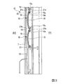
次にシャッターカーテン12の構造について図3〜図6により説明する。シャッターカーテン12はその上端部と下端部の巾木13との間に複数のスラット10が互いに回動可能に上下方向に連結されている。各スラット10は開口14を備えた固定羽15と、固定羽15に対して回動可能な可動羽16とを備え、上側のスラット10の固定羽15の下端部と下側のスラット10の可動羽16の上端部とが回動可能に連結されて上下方向に連なっている。なお、図5、図6において、上側の2枚の可動羽16は固定羽15に当接した閉状態を示し、下側の2枚の可動羽16は固定羽15から開作動した開状態を示しているが、可動羽16は閉状態と開状態または開作動の途中で停止保持可能である。
Next, the structure of the
各スラット10における固定羽15と可動羽16は横幅方向に長尺に形成された略長板状であり、縦断面視で円弧状に湾曲して形成されている。固定羽15は開口14が長円形状に形成され、1または複数、例えば3つの開口14が上下方向に互いに分離して形成されている。なお、各開口14にネットを貼り付けてもよい。
本実施形態に示す例では、図6及び図7に示すように、3つの開口14は固定羽15の縦幅方向の上側に偏って配列されて形成されているが、縦幅方向全体に等間隔に配列形成されていてもよい。固定羽15の複数の開口14を上側に偏らせて配列形成することで、可動羽16が開状態に保持された際に外部から開口14内を視認し難く、太陽光等の外部光は下側の可動羽16の外面と上側の可動羽16の内面に反射して開口14から入射し、柔らかい光を室内で採光することができる。採風についても開状態にある可動羽16と固定羽15の間隙から複数の開口14を通して室内に流入可能であり、その逆も可能である。
The
In the example shown in this embodiment, as shown in FIGS. 6 and 7, the three
なお、一例として、図7(a)、(b)に示すスラット10において、固定羽15の下端から10cm前後の位置に縦幅5mmの開口14を5mm間隔で3カ所上方に形成する。開口14の縦幅を5mm以下にすることで子供の指でも通り抜けられないようにした。最も下側の開口14は開状態の可動羽16の下端より上方に位置するので、安全性と遮光とプライバシーを確保でき、しかも、採光や風の柔らかさや量等を調整することができる。
As an example, in the
しかも、3つの開口14は固定羽15の横幅方向(長手方向)に沿って所定間隔で複数組形成されている。
また、可動羽16は、図5において、中央領域に形成され且つ縦幅方向の長さが固定羽15と略同一で固定羽15の開口14を開閉可能な本体部16aと、その両端部が切り欠かれて縦幅方向の長さの小さい支持部16bとを形成している。そして、固定羽15の両端部と可動羽16の小幅の両支持部16bは両側のガイドレール部7内にそれぞれ挿入されて上下動をガイドされる。
Moreover, a plurality of sets of three
In addition, the
次に、複数のスラット10の連結構造について図3,4及び図8によって説明する。複数のスラット10の連結構造は左右同一構成であり、本実施形態では図8で一方の端部のみを示して説明する。
各スラット10において、固定羽15の上端部には室外側を向く第一フック部15aが形成され、更に第一フック部15aの付け根には可動羽16の開作動をストップさせるストッパー15bが形成されている。また、固定羽15の下端部にも第二フック部15cが形成され、更に第二フック部15cには下側の可動羽16を押圧して開作動させる押圧部18が形成されている。
Next, the connection structure of the plurality of
In each
一方、可動羽16には上端部に固定羽15の第一フック部15a内に回動可能に挿入された断面略円弧状の係止部20と、第一フック部15aを外側から室内側に覆う断面略L字状の第一係合部21aとを備え、更に第一係合部21aの途中から分岐して上方に延びていて、上側に位置するスラット10の固定羽15の下端部に形成した第二フック部15c内に回動可能に挿入される第二係合部21bとが形成されている。上下のスラット10は、上側の固定羽15の第二フック部15cと下側の可動羽16の第二係合部21bとが回動可能に嵌合することで連結されている。
しかも、係止部20と第一係合部21aの間には、上側の固定羽15の押圧部18の押圧を受けて可動羽16を第一フック部15aと第二フック部15cを中心に回動させて開作動させる受け面16cが形成されている。
On the other hand, the
Moreover, the
そのため、図3及び図8において、可動羽16の本体部16aが固定羽15に当接している閉位置にある状態から、シャッターカーテン12をわずかに下方移動させて上側の固定羽15の押圧部18で下側の可動羽16の受け面16cを押すことで、図4に示すように、可動羽16が回動して固定羽15から離間する方向に開作動することになる。この場合、可動羽16の開作動は第一係合部21aが固定羽15のストッパー15bに当接することで停止し、固定羽15に対して可動羽16は所定角度、例えば鋭角で開いた状態に保持される。
この状態で、図7に示すように、固定羽15の開口14は外部から視認し難く、太陽光等の外部光は下側の可動羽16の外面とその上の可動羽16の内面に反射して開口14から入射して採光する。
Therefore, in FIGS. 3 and 8, the
In this state, as shown in FIG. 7, the
また、図8(a)、(b)に示す上下に連結されたスラット10において、固定羽15の上端部に形成された第一フック部15aはその幅方向の長さが両端で短くなっており、その外側で可動羽16の第一係合部21aが切り欠かれた切欠部23を介してその外側端部の第一係合部21aがかしめられて第一かしめ部24Aが形成されている。そのため、各スラット10の固定羽15に対して可動羽16の幅方向の摺動範囲は両端の第一かしめ部24Aで規制されており、スラット10の固定羽15から可動羽16が幅方向に横ずれしたり外れたりすることを阻止できる。
8A and 8B, the
また、上側の固定羽15に形成した下端部の第二フック部15cはその幅方向の長さが両端で短くなっており、その外側で可動羽16の第二係合部21bが切り欠かれた切欠部25を介してその外側端部の第二係合部21bがかしめられて第二かしめ部24Bが形成されている。そのため、上側の固定羽15に対して下側の可動羽16の幅方向の摺動範囲は両端の第二かしめ部24Bで規制されており、上側の固定羽15から下側の可動羽16が幅方向に横ずれしたり外れたりすることを阻止できる。
Further, the
なお、可動羽16の第一係合部21aと第二係合部21bは両側の支持部16b間の長さと同一長さであり、固定羽15の第一フック部15aは第一係合部21aの両側の切欠部23までの長さであり、第二フック部15cは第二係合部21bの両側の切欠部25までの長さを有している。
The
次にシャッターカーテン12の上下動をガイドするガイドレール部7の構造について図9から図14により説明する。ガイドレール部7もシャッターカーテン12の両側に配設されているが、両者は同一構造であるため、一方のガイドレール部7で説明する。
図9、図10、図11に示すように、フレーム3の左右の縦枠3cに固定される一対のガイドレール部7は、シャッターカーテン12の各スラット10を上下動可能にガイドする断面略U字状の受け入れ部27と縦枠3cに連結する取り付け部28とを有している。受け入れ部27の開口を通して各スラット10の固定羽15の端部と可動羽16の支持部16bとが内部に挿入されている。図11に示すように、スラット10が開状態にある場合に、スラット10の両端部の水平方向の開き幅と受け入れ部27の開口幅とをほぼ同一に設定する。
Next, the structure of the
As shown in FIGS. 9, 10, and 11, the pair of
そして、受け入れ部27の対向する内面27a、27bにはそれぞれ繊維体としてモヘア30が基部29に植設されている。モヘア30はガイドレール部7の受け入れ部27の開口とシャッターカーテン12との隙間を埋め、シャッターカーテン12の上下動をガイドする消音材としての機能を有する。
内面27a、27bのモヘア30は複数列の繊維で構成されており、室内側と室外側の内面27a、27bに設けたモヘア30a、30bは図12(a)に示すように比較的太さが小さく硬さが小さい繊維31と比較的太さが大きく硬さが大きい繊維32との2種類の繊維で構成されている。なお、室内側の内面27aに設けたモヘア30aについては図12(b)に示すように一種類の上述した硬さの小さい繊維31で構成されていてもよい。
And the
The
例えば、各内面27a、27bにおけるモヘア30a、30bがガイドレール部7の上下方向に3列で延びているとして、室内側と室外側の内面27a、27bのモヘア30a、30bは図12(a)に示すように柔らかい2列の繊維31と太さが大きく硬い1列の繊維32とで構成されている。或いは、室内側の内面27aのモヘア30aは図12(b)に示すように例えば3列全て繊維31で柔らかく、室外側の内面27bのモヘア31bは図12(a)に示すように柔らかい2列の繊維31と硬い1列の繊維32で構成されていてもよい。
For example, assuming that the
そのため、閉状態にあるスラット10は、図10及び図13に示すように、ガイドレール部7の受け入れ部27の内面27a、27bに設けたモヘア30a、30b間に収まり、上下動可能とされている。
一方、開状態にある各スラット10は、図11及び図14に示すように、可動羽16の小幅の支持部16bが受け入れ部27内の両側の内面27a,27bのモヘア30a、30bに当接する。特に室外側で第一及び第二係合部21a、21bから比較的離間した支持部16bの端部が硬さの大きい繊維32の列を混在させたモヘア30bに当接することで、自重による降下に抵抗して阻止する。また、手動等で、スラット10を外部から上側に上げようとした場合にもモヘア30a、30b、特に硬さの大きい繊維32の列で抵抗する。更に、閉状態でも各スラット10を両側のモヘア30a,30bに当接しないかわずかに当接する程度であるため、シャッターカーテン12の開閉操作音を消音して上下動可能に保持できる。
Therefore, the
On the other hand, as shown in FIGS. 11 and 14, in each
本実施形態によるシャッター装置1は上述した構成を備えており、次にその作用を説明する。シャッターカーテン12が建物の開口部2を開口状態から閉鎖状態に閉じる場合、図示しないスイッチによって駆動モータ9を一方向に回転駆動させてシャッターカーテン12をシャフト8に巻き上げた状態から繰り出し、図2及び図3に示すように、シャッターカーテン12の各スラット10の可動羽16が固定羽15に当接した閉状態で、両側のガイドレール部7にガイドされて降下させる。
The shutter device 1 according to the present embodiment has the above-described configuration, and the operation thereof will be described next. When the
そして、シャッターカーテン12の下端部の巾木13がフレーム3の下枠3bに当接して、負荷が変化することを駆動モータ9に取り付けたエンコーダ等の検知手段で検知するか、巾木13または下枠3b等に設けたセンサ等で検知することで停止する。この状態で開口部2はシャッターカーテン12で閉鎖されている。
Then, the
この状態から、通風または採光のために可動羽16を開作動させるには、更に駆動モータ9でシャッターカーテン12をわずかに下方移動させる。これによって、各スラット10の固定羽15の下端部の押圧部18で下側のスラット10の可動羽16の受け面16cを押すことで、可動羽16が第一フック部15aを嵌合する第一係合部21aと第二フック部15cに嵌合される第二係合部21bとを中心に回転することで所定角度だけ室外側に開作動し、第一係合部21aが固定羽15のストッパー15bに当接して開状態で停止する。
In order to open the
この状態で、図7に示すように、屋外の風が固定羽15の開口14を通して室内に送られ、太陽光等の光が下側の可動羽16や上側の可動羽16で反射して開口14を通して室内を柔らかい光が照射する。採風も同様に固定羽15の開口14を通して室内外に柔らかく流通する。また、開状態にある可動羽16の下端部より上方に固定羽15の複数の開口14が配設されているから、外部から開口14を通して室内を視認し難く、各開口14の縦幅も小さいのでプライバシーを保護すると共に防犯上の安全性を向上できる。
In this state, as shown in FIG. 7, outdoor wind is sent indoors through the
また、建物の開口部2を開放するには、駆動モータ9を逆回転させてシャッターカーテン12を若干上方移動させることで押圧部18が可動羽16の受け面16cから離れ、可動羽16をその自重によって固定羽15に当接させて開口14を閉作動させる。その後、駆動モータ9を更に逆回転させてシャッターカーテン12をシャフト8に巻き上げればよい。
また、各スラット10が閉状態で上下動する場合には、図10及び図13に示すように、各スラット10の固定羽15と可動羽16は、その両端部がガイドレール部7の各受け入れ部27における内面27a、27bのモヘア30a、30b間でいなして消音させて上下動する。また、スラット10の可動羽16を外部から人為的に開こうとしても、両内面27a、27bのモヘア30a、30bが当接して抵抗する。
Further, in order to open the
Further, when each
一方、スラット10の可動羽16が固定羽15に対して開状態にある場合には、スラット10はガイドレール部7の各受け入れ部27における内面27a、27bのモヘア30a、30b間と同一幅になり、互いに当接する。しかも、図11及び図14に示すように、可動羽16の両端の支持部16bは開いた状態で内面27bの硬い繊維32を含むモヘア30bに当接することで、自重による降下方向の荷重に対して抵抗し、モヘア30a、30bの硬さで可動羽16を開状態に維持する。また、固定羽15の押圧部18が可動羽16の受け面16cから離れた場合には支持部16bがモヘア30b,30aの抵抗に打ち勝って自重で閉作動することを許容する。
On the other hand, when the
しかも、上述したシャッターカーテン12の開閉作動と、各スラット10における可動羽16が開口14を設けた固定羽15に対する開閉作動を行うに際し、各可動羽16は第一かしめ部24Aと第二かしめ部24Bによって固定羽15に対して横ずれすることを規制できる。
Moreover, when the opening / closing operation of the
上述のように、本実施形態によるシャッター装置1によれば、シャッターカーテン12の各スラット10において、可動羽16は第一かしめ部24Aによって固定羽15の第一フック部15aに対して横ずれしないように規制されるため、組立後に可動羽16が固定羽15から横ずれしたり、外れたりすることを規制できる。また、各可動羽16は第二かしめ部24Bによって上側の固定羽15の第二フック部15cに対して横ずれしないように規制されるため、組立後に可動羽16を含むスラット10が上側のスラット10の固定羽15から横ずれしたり、外れたりすることを規制できる。
As described above, according to the shutter device 1 according to the present embodiment, in each
また、可動羽16の第一係合部21aの両端に設けた第一かしめ部24Aと第二係合部21bの両端に設けた第二かしめ部24Bは、それぞれ切欠部23,25によって相対回動に寄与するその内側の部分と分離されているため、第一係合部21a及び第二係合部21bの両端部をかしめても固定羽15に対する可動羽16の回動に影響を与えない。
そのため、本実施形態によるシャッター装置1は、別部品の取り付け工程をなくして自動機による製造を容易にして加工コストを低廉にできる。しかも、第一及び第二かしめ部24A、24Bを可動羽16の同一面側に設けたので、かしめ作業が一層容易である。
Further, the
For this reason, the shutter device 1 according to the present embodiment can be easily manufactured by an automatic machine without a separate component attaching step, and the processing cost can be reduced. Moreover, since the first and
また、各スラット10の両端部を挿入して上下動をガイドするガイドレール部7の各受け入れ部27の内面27a、27bにモヘア30a、30bを設け、少なくとも室外側のモヘア30bは繊維31に硬さの比較的大きい繊維32を混在させたので、可動羽16が開いた際に支持部16bに当接するモヘア30bの抵抗を大きくすることで、支持部16bを安定して係止させて開状態に維持できると共にモヘア30a、30bの経年劣化を抑制できる。しかも、可動羽16が閉状態では、モヘア30a、30bによってスラット10をいなすことで安定して上下動させることができる。
Further,
また、各スラット10において、固定羽15の上側に偏らせて複数の開口14を配列させたため、可動羽16を開状態にした場合、室外から開口14を通して室内を他人が視認することを抑制できるので、安全性と遮光とプライバシーを確保できると共に、開口14を通る採光や風の量を調整することをバランスさせることができる。
Further, in each
なお、本発明によるシャッター装置1は、上述した実施形態に限定されるものではなく、本発明の要旨を逸脱しない範囲で適宜の変更や置換等が可能である。以下に、本発明の変形例について説明するが、上述した実施形態で説明した部品や部材等と同一または同様なものについては同一の符号を用いて説明する。 The shutter device 1 according to the present invention is not limited to the above-described embodiment, and can be appropriately changed or replaced without departing from the gist of the present invention. Hereinafter, modifications of the present invention will be described, but the same or similar components or members described in the above-described embodiment will be described using the same reference numerals.
例えば、上述した実施形態では、可動羽16における第一係合部21aの両端に形成した第一かしめ部24Aの内側に切欠部23を形成したが、切欠部23は設けなくてもよい。この場合、少なくとも固定羽15の第一フック部15aの両端部の外側に離間した位置で可動羽16の第一係合部21aに(第一フック部15aとの相対回動に影響を与えないように)第一かしめ部24Aを形成すればよい。同様に、固定羽15の第二フック部15cの両端部の外側に離間した位置で可動羽16の第二係合部21bに(第二フック部15cとの相対回動に影響を与えないように)第二かしめ部24Bを形成すれば、第二係合部21bに切欠部25を設けなくてもよい。これらによって、固定羽15と可動羽16の相対回動に悪影響を与えないで第一及び第二かしめ部24A,24Bを形成できる。
For example, in the above-described embodiment, the
また、上述した実施形態では、可動羽16の第一係合部21aと第二係合部21bの両端部に第一かしめ部24Aと第二かしめ部24Bをそれぞれ形成して固定羽15の第一フック部15a、第二フック部15cと横ずれしたりしないようにしたが、この構成に代えて可動羽16の第一係合部21aと第二係合部21bの両端を短く形成し、固定羽15の第一フック部15aと第二フック部15cを第一係合部21aと第二係合部21bより両端を長く形成し、第一係合部21aと第二係合部21bの両端外側に切欠部を形成して、或いは切欠部を形成しないで、その外側の両端部に第一かしめ部24Aと第二かしめ部24Bをそれぞれ形成して可動羽16の横ずれを防ぐようにしてもよい。
In the above-described embodiment, the
なお、繊維体としてのモヘア30a、30bとして、ガイドレール部7の受け入れ部27の対向する両内面27a、27bに比較的太さの大きい繊維32と太さの小さい繊維31を混在させたモヘア30a、30bを設置したが、室内側の内面27aに設けたモヘア30aは硬さの小さい繊維31だけを長手方向に沿って配列させて構成してもよい。この場合でも、可動羽16の支持部16bがモヘア30a、30bに当接して開状態に維持される。或いは、室外側の内面27bのモヘア30bを硬さの小さい繊維31だけで構成してもよい。
また、モヘア30a、30bにおいて、太さの大きい繊維32は太さの小さい繊維31の列に並んで配列する構成に限定されるものではなく、繊維31の任意の列に混在させてもよく、或いは複数の列にランダムに混在させてもよい。モヘア30b等を構成する繊維は2種類に限定されるものではなく、硬さの異なる3種類以上でもよい。
In addition, as
Further, in the
また、可動羽16の支持部16bを開状態で維持する抵抗体として、モヘア30に限定されるものではなく、例えばスポンジ等の弾性体等、他の抵抗体を設けてもよい。
Further, the resistor that maintains the
また、固定羽15に設けた開口14は縦幅方向に3つに限定されるものではなく、2つまたは4つ以上でもよく、適宜の複数の開口14を形成できる。また、開口14は固定羽15の横幅方向に延在するものに限定されない。例えば、固定羽15の縦幅方向に延びる開口14を横幅方向に複数配列させて1組の開口としてもよい。或いは、開口14を斜めに形成して平行に複数配列させてもよい。また、上述した実施形態では、固定羽15の開口14は、開状態にある可動羽16の下端部の水平方向の延長線に対して上側に偏心して位置させたが、下側にずれていてもよい。
Further, the number of the
なお、本発明における固定羽の第一フック部15aは第一保持部を構成し、第二フック部15cは第二保持部を構成する。
In addition, the
1 シャッター装置
2 開口部
7 ガイドレール部
10 スラット
12 シャッターカーテン
14 開口
15 固定羽
15a 第一フック部
15b ストッパー
15c 第二フック部
16 可動羽
16a 本体部
16b 支持部
16c 受け面
18 押圧部
20a 係止部
21a 第一係合部
21b 第二係合部
23、25 切欠部
24A 第一かしめ部
24B 第二かしめ部
27 受け入れ部
30,30a、30b モヘア
31、32 繊維
DESCRIPTION OF SYMBOLS 1
Claims (3)
前記スラットの端部の上下動をガイドする受け入れ部を有するガイドレール部と、
前記ガイドレール部の受け入れ部内に対向して設けられていて前記可動羽の端部に設けた支持部に当接可能な抵抗体とを備え、
少なくともいずれか一方の前記抵抗体は、一部の前記抵抗体が他の前記抵抗体より接触抵抗が大きいものを混在させたことを特徴とするシャッター装置。 A shutter device in which a plurality of slats including a fixed wing provided with an opening and a movable wing capable of opening and closing the opening are connected in the vertical direction, and the movable wing is opened by relative movement of the upper and lower slats. Because
A guide rail portion having a receiving portion for guiding the vertical movement of the end portion of the slat;
A resistor provided opposite to the receiving portion of the guide rail portion and capable of contacting a support portion provided at an end of the movable wing;
At least one of the resistors is a shutter device in which some of the resistors have a contact resistance larger than that of the other resistors.
Priority Applications (2)
| Application Number | Priority Date | Filing Date | Title |
|---|---|---|---|
| JP2013240297A JP6182759B2 (en) | 2013-11-20 | 2013-11-20 | Shutter device |
| PCT/JP2014/080753 WO2015076330A1 (en) | 2013-11-20 | 2014-11-20 | Shutter device |
Applications Claiming Priority (1)
| Application Number | Priority Date | Filing Date | Title |
|---|---|---|---|
| JP2013240297A JP6182759B2 (en) | 2013-11-20 | 2013-11-20 | Shutter device |
Publications (2)
| Publication Number | Publication Date |
|---|---|
| JP2015098748A JP2015098748A (en) | 2015-05-28 |
| JP6182759B2 true JP6182759B2 (en) | 2017-08-23 |
Family
ID=53375534
Family Applications (1)
| Application Number | Title | Priority Date | Filing Date |
|---|---|---|---|
| JP2013240297A Active JP6182759B2 (en) | 2013-11-20 | 2013-11-20 | Shutter device |
Country Status (1)
| Country | Link |
|---|---|
| JP (1) | JP6182759B2 (en) |
Families Citing this family (1)
| Publication number | Priority date | Publication date | Assignee | Title |
|---|---|---|---|---|
| JP6122081B1 (en) * | 2015-10-20 | 2017-04-26 | 積水ハウス株式会社 | Blind shutter |
Family Cites Families (4)
| Publication number | Priority date | Publication date | Assignee | Title |
|---|---|---|---|---|
| JPH0656481U (en) * | 1992-12-28 | 1994-08-05 | 昭和オリファ株式会社 | Insulation curtain device |
| JP4925733B2 (en) * | 2006-06-06 | 2012-05-09 | 三和シヤッター工業株式会社 | Silent structure for shutter |
| ES2365048T3 (en) * | 2007-09-20 | 2011-09-21 | Peter Bichler | ROLLING BLIND AND CORRESPONDING ELEMENT. |
| JP5770660B2 (en) * | 2012-03-14 | 2015-08-26 | 三和シヤッター工業株式会社 | Window shutter fire prevention structure |
-
2013
- 2013-11-20 JP JP2013240297A patent/JP6182759B2/en active Active
Also Published As
| Publication number | Publication date |
|---|---|
| JP2015098748A (en) | 2015-05-28 |
Similar Documents
| Publication | Publication Date | Title |
|---|---|---|
| US7472738B2 (en) | Screen device | |
| FI70978B (en) | LAMELLGARDIN | |
| JP5473258B2 (en) | Roll blind weight bar | |
| KR20180128362A (en) | Bottom rail assembly for a covering with adjustable roller position and related methods | |
| EP2900894B1 (en) | Control and movement device for mosquito screens, curtains and the like | |
| KR101048674B1 (en) | Roll blinds | |
| EP2405096B1 (en) | Device for winding up and unwinding raising cords of a screen such as a window covering | |
| JP6182759B2 (en) | Shutter device | |
| KR20150083999A (en) | Covering device | |
| ITBO20120024U1 (en) | GUIDE GROUP, FOR CURTAINS, OUTDOOR TENDONS AND SIMILAR DEVICES | |
| JP6182760B2 (en) | Shutter device | |
| JP6291225B2 (en) | Shutter device | |
| JP4126380B1 (en) | Folding shutter | |
| WO2015076330A1 (en) | Shutter device | |
| JP5353941B2 (en) | Structure of blind device and window frame | |
| JP2010270496A (en) | Structure with ventilation function | |
| JP7002995B2 (en) | Automatic door device | |
| JP6454134B2 (en) | Shutter box mounting structure | |
| JP2009243103A (en) | Wire screen device | |
| JP2011169086A (en) | Blind | |
| KR101920255B1 (en) | Blind Integrated Window | |
| JP2012097492A (en) | Roll screen device | |
| JP7236226B2 (en) | Shielding device | |
| JP2016069948A (en) | shutter | |
| JP6695733B2 (en) | Guide member |
Legal Events
| Date | Code | Title | Description |
|---|---|---|---|
| A621 | Written request for application examination |
Free format text: JAPANESE INTERMEDIATE CODE: A621 Effective date: 20160628 |
|
| TRDD | Decision of grant or rejection written | ||
| A01 | Written decision to grant a patent or to grant a registration (utility model) |
Free format text: JAPANESE INTERMEDIATE CODE: A01 Effective date: 20170627 |
|
| A61 | First payment of annual fees (during grant procedure) |
Free format text: JAPANESE INTERMEDIATE CODE: A61 Effective date: 20170630 |
|
| R150 | Certificate of patent or registration of utility model |
Ref document number: 6182759 Country of ref document: JP Free format text: JAPANESE INTERMEDIATE CODE: R150 |
|
| S111 | Request for change of ownership or part of ownership |
Free format text: JAPANESE INTERMEDIATE CODE: R313111 |
|
| R350 | Written notification of registration of transfer |
Free format text: JAPANESE INTERMEDIATE CODE: R350 |