JP6181498B2 - Antenna device - Google Patents
Antenna device Download PDFInfo
- Publication number
- JP6181498B2 JP6181498B2 JP2013201983A JP2013201983A JP6181498B2 JP 6181498 B2 JP6181498 B2 JP 6181498B2 JP 2013201983 A JP2013201983 A JP 2013201983A JP 2013201983 A JP2013201983 A JP 2013201983A JP 6181498 B2 JP6181498 B2 JP 6181498B2
- Authority
- JP
- Japan
- Prior art keywords
- antenna
- shielding plate
- base
- radiating element
- integrated
- Prior art date
- Legal status (The legal status is an assumption and is not a legal conclusion. Google has not performed a legal analysis and makes no representation as to the accuracy of the status listed.)
- Expired - Fee Related
Links
Images


Landscapes
- Variable-Direction Aerials And Aerial Arrays (AREA)
- Details Of Aerials (AREA)
Description
本発明は、複数のアンテナを搭載したアンテナ装置に関する。 The present invention relates to an antenna device equipped with a plurality of antennas.
従来、複数のアンテナを搭載した統合アンテナ装置が利用されている。このような統合アンテナは、例えば、移動体(例えば、自動車、鉄道車両、船舶、等)、または、移動端末(例えば、スマートフォン、携帯電話機、PDA(Personal Digital Assistance)、タブレット端末、等)に搭載される。例えば、下記特許文献1には、3G(3rd Generation:第3世代携帯電話)用の第1の平面アンテナ、地上デジタル放送用の第2の平面アンテナ、および、GPS(Global Positioning System:全地球測位システム)用の第3の平面アンテナを備えた、統合アンテナ装置が開示されている。このような、統合アンテナを使用することで、例えば、アンテナ装置の小型化、設置スペースの削減、設置コストの削減、等の効果が得られる。
Conventionally, an integrated antenna device equipped with a plurality of antennas has been used. Such an integrated antenna is mounted on, for example, a mobile body (for example, an automobile, a railway vehicle, a ship, etc.) or a mobile terminal (for example, a smartphone, a mobile phone, a PDA (Personal Digital Assistance), a tablet terminal, etc.). Is done. For example, the following
しかしながら、従来の統合アンテナ装置においては、複数のアンテナが互いに近接している場合、良好なアイソレーション特性を得ることができなくなる虞がある。したがって、従来の統合アンテナ装置では、良好なアイソレーション特性を得るためには、複数のアンテナを互いに離間させる必要がある。このため、従来の統合アンテナ装置では、良好なアイソレーション特性を得つつ、統合アンテナ装置を小型化することは困難であった。 However, in the conventional integrated antenna device, there is a possibility that good isolation characteristics cannot be obtained when a plurality of antennas are close to each other. Therefore, in the conventional integrated antenna device, it is necessary to separate a plurality of antennas from each other in order to obtain good isolation characteristics. For this reason, in the conventional integrated antenna device, it has been difficult to reduce the size of the integrated antenna device while obtaining good isolation characteristics.
本発明は、上記の問題に鑑みてなされたものであり、その目的は、良好なアイソレーション特性を得ることが可能な、小型の統合アンテナを実現することにある。 The present invention has been made in view of the above problems, and an object thereof is to realize a small integrated antenna capable of obtaining a good isolation characteristic.
上記課題を解決するために、本発明に係るアンテナ装置は、ベースと、前記ベースをグラウンドとして使用する逆Fアンテナであって、前記ベースの表面と対向する平面上に放射素子を有する第1のアンテナと、前記第1のアンテナの放射素子と同一面上に放射素子を有する第2のアンテナと、前記第1のアンテナと前記第2のアンテナとの間において、前記ベースの表面に立設された第1の遮蔽板と、を備えることを特徴とする。 In order to solve the above-described problems, an antenna device according to the present invention is a first inverted F antenna using a base and the base as a ground, and has a radiating element on a plane facing the surface of the base. An antenna, a second antenna having a radiating element on the same plane as the radiating element of the first antenna, and a surface of the base between the first antenna and the second antenna. And a first shielding plate.
上記構成によれば、第1のアンテナと第2のアンテナとの間において、第1のアンテナから第2のアンテナ方向に放射された電波を、第1の遮蔽板によって遮蔽することができる。特に、第1のアンテナと第2のアンテナとの間の隙間に、遮蔽板を立設させる構成を採用しているため、第1のアンテナと第2のアンテナとの間隔を広げることなく、第2のアンテナに対する第1のアンテナの放射の影響を抑制することができる。すなわち、上記構成によれば、統合アンテナを大型化することなく、良好なアイソレーション特性を得ることができる。さらに、上記構成によれば、第1の遮蔽板を設けるだけといった簡単な構成により、比較的低コストで、上記第1のアンテナの放射の影響を抑制することができる。 According to the above configuration, radio waves radiated from the first antenna toward the second antenna can be shielded by the first shielding plate between the first antenna and the second antenna. In particular, since a configuration in which a shielding plate is erected in the gap between the first antenna and the second antenna is employed, the first antenna and the second antenna can be increased without increasing the distance between them. The influence of the radiation of the first antenna on the second antenna can be suppressed. That is, according to the said structure, a favorable isolation characteristic can be acquired, without enlarging an integrated antenna. Furthermore, according to the above configuration, the influence of the radiation of the first antenna can be suppressed at a relatively low cost by a simple configuration in which only the first shielding plate is provided.
上記アンテナ装置において、前記第2のアンテナは、円偏波受信用アンテナであり、前記アンテナ装置は、前記ベースの表面に立設された第2の遮蔽板をさらに備え、前記第1の遮蔽板および前記第2の遮蔽板は、前記第2のアンテナを間に挟んで、互いに対称的な位置に配置されていることが好ましい。 In the antenna device, the second antenna is a circularly polarized wave receiving antenna, and the antenna device further includes a second shielding plate erected on the surface of the base, and the first shielding plate It is preferable that the second shielding plate is disposed at a symmetrical position with the second antenna interposed therebetween.
上記構成によれば、第2のアンテナの周囲において、第1の遮蔽板と第2の遮蔽板とが互いに対称的に配置されるため、第2のアンテナにおける放射パターンの偏り(最大利得方向の傾き)を抑制することができる。特に、円偏波受信用アンテナは、地平面に対して垂直な方向に最大利得が得られることが好ましいとされるため、このような放射パターンの偏りを抑制する構成が有用である。 According to the above configuration, since the first shielding plate and the second shielding plate are arranged symmetrically around the second antenna, the bias of the radiation pattern in the second antenna (in the maximum gain direction) (Tilt) can be suppressed. In particular, since it is preferable that the circularly polarized wave receiving antenna has a maximum gain in a direction perpendicular to the ground plane, a configuration that suppresses such a deviation in the radiation pattern is useful.
上記アンテナ装置において、前記第1のアンテナの放射素子および前記第2のアンテナの放射素子と同一面上に放射素子を有する第3のアンテナをさらに備え、前記第2の遮蔽板は、前記第2のアンテナと前記第3のアンテナとの間において、前記ベースの表面に立設されていることが好ましい。 The antenna device may further include a third antenna having a radiating element on the same plane as the radiating element of the first antenna and the radiating element of the second antenna, and the second shielding plate may include the second shielding plate. It is preferable to stand on the surface of the base between the third antenna and the third antenna.
上記構成によれば、さらに、第3のアンテナを実装しつつ、第3のアンテナの放射による影響(または、第3のアンテナに対する放射の影響)を抑制することができる。 According to the said structure, the influence by the radiation | emission of a 3rd antenna (or the influence of the radiation | emission with respect to a 3rd antenna) can be suppressed further, mounting a 3rd antenna.
上記アンテナ装置において、前記第1の遮蔽板の上端部の高さ位置は、前記第1のアンテナの放射素子および前記第2のアンテナの放射素子との同一面の高さ以上であることが好ましい。 In the antenna device, the height position of the upper end portion of the first shielding plate is preferably equal to or higher than the height of the same surface of the radiating element of the first antenna and the radiating element of the second antenna. .
上記構成によれば、第1のアンテナから第2のアンテナ方向に放射された電波の遮蔽度を高めることができるため、第2のアンテナに対する第1のアンテナの放射の影響の抑制効果を高めることができる。 According to the above configuration, since the shielding degree of the radio wave radiated from the first antenna toward the second antenna can be increased, the effect of suppressing the influence of the radiation of the first antenna on the second antenna is enhanced. Can do.
上記アンテナ装置において、前記第1の遮蔽板には、前記ベースの表面と交わる方向に切り欠かれたスリットが、前記ベースの表面に沿って複数並べて形成されていてもよい。 In the antenna device, a plurality of slits cut out in a direction intersecting the surface of the base may be formed in the first shielding plate along the surface of the base.
上記構成によれば、特定の周波数帯域における、第1のアンテナの送信波が第2のアンテナに及ぼす影響(アイソレーション特性)を、より良好なものへと調整することができる。特に、各スリットの幅、および、隣り合うスリットの間隔を適切に調整することにより、第2のアンテナの動作帯域におけるアイソレーション特性を、より良好なものへと調整することができる。 According to the above configuration, the influence (isolation characteristics) that the transmission wave of the first antenna has on the second antenna in a specific frequency band can be adjusted to a better one. In particular, by appropriately adjusting the width of each slit and the interval between adjacent slits, the isolation characteristic in the operating band of the second antenna can be adjusted to a better one.
本発明によれば、良好なアイソレーション特性を得ることが可能な、小型の統合アンテナを実現することができる。 According to the present invention, it is possible to realize a small integrated antenna capable of obtaining good isolation characteristics.
以下、添付の図面を参照して、本発明の一実施形態に係るアンテナ装置について説明する。なお、本書において、「水平」(または「平行」)との表現は、対象物に対して概ね水平(または平行)であればよく、少なくとも対象物に沿っていればよいことを意図したものであり、したがって、厳密な水平(または「平行」)状態から多少の傾きを有していたとしても、「水平」(または「平行」)の概念に含まれる。同様に、「垂直」との表現は、対象物に対して概ね垂直であればよく、少なくとも対象物と交わる方向に沿っていればよいことを意図したものであり、したがって、厳密な垂直状態から多少の傾きを有していたとしても、「垂直」の概念に含まれる。さらに、本書において、「同一」との表現は、対象物に対して概ね同一であればよく、したがって、厳密に同一な状態から多少のズレが生じていたとしても、「同一」の概念に含まれる。 Hereinafter, an antenna device according to an embodiment of the present invention will be described with reference to the accompanying drawings. In this document, the expression “horizontal” (or “parallel”) is intended to be substantially horizontal (or parallel) to the object, and at least along the object. Therefore, even if there is a slight inclination from the strictly horizontal (or “parallel”) state, it is included in the concept of “horizontal” (or “parallel”). Similarly, the expression “vertical” is intended to be substantially perpendicular to the object, and at least along the direction intersecting the object, and therefore from a strictly vertical state. Even if it has a slight inclination, it is included in the concept of “vertical”. Further, in this document, the expression “same” may be substantially the same as the object, and therefore, even if there is a slight deviation from the exact same state, it is included in the concept of “same”. It is.
〔第1実施形態〕
初めに、図1〜図3を参照して、本発明の第1実施形態に係る統合アンテナ装置100Aについて説明する。図1は、本発明の第1実施形態に係る統合アンテナ装置100Aの構成を示す外観斜視図である。図2は、図1に示す統合アンテナ装置100Aの上面図である。図3は、図2に示す統合アンテナ装置100AのA−A断面図である。
[First Embodiment]
First, an integrated
本実施形態の統合アンテナ装置100Aは、1つの逆Fアンテナ(直線偏波送信用のアンテナ)および2つのループアンテナ(円偏波受信用のアンテナ)が、一枚のベース(後述するベース101)上に統合されたアンテナ装置であり、例えば、自動車用のアンテナ装置として、自動車のルーフ部に装着される。図1に示すように、統合アンテナ装置100Aは、ベース101と、第1のアンテナ110と、第2のアンテナ120と、第1の遮蔽板130と、を備えている。図1に示すように、統合アンテナ装置100Aは、上記3つのアンテナがベース101上に立体的に配置された構成を有しており、特に、上記逆Fアンテナ(第1のアンテナ110)が立体的な形状を有しているため、当該逆Fアンテナによる平面占有面積が小さく、これにより、装置全体の小型化が実現されている。
In the integrated
(ベース101)
ベース101は、その表面上に各構成部材(第1のアンテナ110、第2のアンテナ120、第1の遮蔽板130)が配置される、板状部材である。ベース101は、後述する第1のアンテナ110のグラウンド板として機能するように、導電性を有する材料(例えば、銅、アルミニウムなどの金属)が用いられる。
(Base 101)
The
(第1のアンテナ110)
第1のアンテナ110は、水平面と垂直面とが組み合わされた立体的な形状を有する逆Fアンテナであり、LTE(Long Term Evolution)アンテナとして機能する。LTEアンテナの動作帯域は、例えば、698〜960MHz、1427〜1510MHz、1710〜2690MHzである。第1のアンテナ110は、その一部分(後述する第1の部分112A)が支持板104の表面上に実装されている。支持板104は、ベース101の表面に対して平行な(すなわち、水平な)板状部材である。支持板104は、ベース101の表面に立設された支柱105によって、その裏側が支持されている。本実施形態では、支持板104の材料としてアクリル樹脂を用いているが、これに限らない。
(First antenna 110)
The
(第2のアンテナ120)
第2のアンテナ120は、平面状の2つのループアンテナが同一基板上に統合されたものである。上記2つのループアンテナのうち、一のループアンテナはGPSアンテナ(動作周波数:1575.42MHz)として機能し、他のループアンテナはSDARS(Satellite Digital Audio Radio Service)アンテナ(動作帯域:2320〜2345MHz)として機能する。第2のアンテナ120は、平板状を有しており、支持板102の表面上に実装されている。支持板102は、ベース101の表面に対して平行な(すなわち、水平な)板状部材である。支持板102は、ベースの表面に立設された支柱103によって、その裏側が支持されている。本実施形態では、支持板102の材料としてアクリル樹脂を用いているが、これに限らない。なお、ベース101と支持板102との間に形成されている空間には、他の構成部材(例えば、各アンテナにて生成された電気信号を増幅するためのアンテナ回路)が設けられてもよい。これにより、ベース101上のスペースを有効に利用することができ、アンテナ装置のさらなる小型化が可能となる。
(Second antenna 120)
The
(第1のアンテナ110の具体的な構成)
図1に示すように、第1のアンテナ110は、アンテナ基板111と、当該アンテナ基板111の表面上に形成されたアンテナパターン112とを備えて構成されている。アンテナ基板111には、例えば、薄板状の誘電体フィルム(例えば、ポリイミドフィルム)が用いられる。アンテナパターン112には、例えば、薄膜状の導体箔(例えば、銅箔)が用いられる。アンテナパターン112は、第1の部分112A、第2の部分112B、第3の部分112C、および、第4の部分112Dを有する。
(Specific configuration of first antenna 110)
As shown in FIG. 1, the
第1の部分112Aは、ベース101の表面に対して平行な部分であり、支持板102の表面上に実装されている部分である。また、第1の部分112Aは、第2のアンテナの放射素子と同一平面上に形成されている部分である。第4の部分112Dは、ベース101の表面に対して平行な部分であり、ベース101の表面上に実装されている部分である。第1の部分112Aおよび第4の部分112Dは、互いに平行である。
The first portion 112 </ b> A is a portion that is parallel to the surface of the
第2の部分112Bおよび第3の部分112Cは、ベース101の表面に対して垂直な部分であり、第1の部分112Aの縁部と第4の部分112Dの縁部との間に形成されている部分である。このうち、第2の部分112Bは、その上縁部が第1の部分112Aの縁部と連結されており、その下縁部が第4の部分112Dの縁部と連結されている。一方、第3の部分112Cは、その上縁部が第1の部分112Aの縁部と連結されているが、その下縁部は第4の部分112Dの縁部と連結されていない。すなわち、図1に示すように、第3の部分112Cの下縁部と、第4の部分112Dとの間には隙間が生じている。この隙間を挟んで、第3の部分112Cおよび第4の部分112Dの各々に、逆Fアンテナの給電点が設けられる。例えば、同軸ケーブルの内側導体が、第3の部分112Cの給電点(図示省略)に接続され、同軸ケーブルの外側導体が、第4の部分112Dの給電点(図示省略)に接続される。なお、図1に示す例では、第1の部分112Aの裏面のみが、支持板102によって支持されているが、第2の部分112Bおよび第3の部分112Cの裏面も、支持板等によって支持されてもよい。
The
このように構成されたアンテナパターン112は、第1の部分112Aおよび第3の部分112Cが、逆Fアンテナの放射素子として機能し、第4の部分112Dが、逆Fアンテナのグラウンドとして機能し、第2の部分112Bが、逆Fアンテナの短絡部として機能する。なお、第4の部分112Dは、ベース101の表面上に面接触しているため、当該ベース101は、第1のアンテナ110のグラウンドとして機能する。
In the antenna pattern 112 configured in this manner, the
上述した第1のアンテナ110の立体的な形状は、例えば、平面状のアンテナ基板111の表面に対し、第1の部分112A、第2の部分112B、第3の部分112C、および、第4の部分112Dを一体的に形成した後、各部の境界部分(第1の部分112Aと第2の部分112Bとの境界部分、第1の部分112Aと第3の部分112Cとの境界部分、および、第3の部分112Cと第4の部分112Dとの境界部分)を山折りに折り曲げることにより、形成することができる。
The three-dimensional shape of the
(第2のアンテナ120の具体的な構成)
図2に示すように、第2のアンテナ120は、アンテナ基板121と、当該アンテナ基板121の表面上に形成されたアンテナパターン122A,122B,123A,123Bとを備えて構成されている。上記アンテナ基板121には、例えば、薄板状の誘電体フィルム(例えば、ポリイミドフィルム)が用いられる。上記各アンテナパターンには、例えば、薄膜状の導体箔(例えば、銅箔)が用いられる。
(Specific configuration of second antenna 120)
As shown in FIG. 2, the
アンテナパターン122Aおよびアンテナパターン122Bは、上述のSDARSアンテナを構成する。図2に示すように、アンテナパターン122Aは、概ね楕円形の環状を成しており、ループアンテナの放射素子として機能する。アンテナパターン122Bは、アンテナパターン122Aの周囲を取り囲むような、概ね矩形状を有しており、ループアンテナの無給電素子として機能する。
The
一方、アンテナパターン123Aおよびアンテナパターン123Bは、上述のGPSアンテナを構成する。アンテナパターン123Aは、アンテナパターン122Bの周囲を取り囲むような、概ね矩形の環状を成しており、ループアンテナの放射素子として機能する。アンテナパターン123Bは、アンテナパターン123Aの周囲を取り囲むような形状を有しており、ループアンテナの無給電素子として機能する。
On the other hand, the
本実施形態では、アンテナパターン123Bは、2本の帯状の導体箔からなる。上記2本の導体箔のうち、一の導体箔は、上記アンテナパターン123Aがなす四角形の左辺(図中x軸負側の辺)および下辺(図中y軸負側の辺)に沿った、直角に折れ曲がるL字形状をなしている。一方、他の導体箔は、上記四角形の右辺(図中x軸正側の辺)および上辺(図中y軸正側の辺)に沿った、直角に折れ曲がるL字形状をなしている。
In the present embodiment, the
なお、上述の各ループアンテナにおいて、上記無給電素子は、放射素子から離隔されており、無給電素子と放射素子との間には、直流的な導通がない。無給電素子を設けたことにより、ループアンテナの入力インピーダンスを変化させ、インピーダンス整合を図ることが可能となっている。また、無給電素子を設けたことにより、ループアンテナにおけるゲインの集中を緩和し、ゲインの集中に起因する受信障害(例えば、衛星が天頂以外の方向に位置する場合や、アンテナ形成面を水平に保てなかった場合に生じる受信障害)を抑制することが可能となっている。 In each loop antenna described above, the parasitic element is separated from the radiating element, and there is no DC conduction between the parasitic element and the radiating element. By providing the parasitic element, it is possible to change the input impedance of the loop antenna to achieve impedance matching. Also, by providing a parasitic element, the gain concentration in the loop antenna is reduced, and reception interference caused by gain concentration (for example, when the satellite is located in a direction other than the zenith, It is possible to suppress a reception failure that occurs when it cannot be maintained.
(第1の遮蔽板130)
本実施形態の統合アンテナ装置100Aにおいて、注目すべきは、第1の遮蔽板130が設けられている点である。第1の遮蔽板130は、第1のアンテナ110と第2のアンテナ120とを互いに遮蔽するように、第1のアンテナ110と第2のアンテナ120との間において、ベース101の表面上に垂直に立設されている板状部材である。第1の遮蔽板130には、導電性を有する材料(例えば、銅、アルミニウムなどの金属)が用いられる。
(First shielding plate 130)
What should be noted in the
図2に示すように、統合アンテナ装置100Aを上方(図中z軸正方向)から見たとき、第2のアンテナ120は、矩形状を成しており、第1のアンテナ110は、第2のアンテナ120の外側において、第2のアンテナ120の左辺および下辺に沿って、直角に折れ曲がるL字状を成している。このように、第1のアンテナ110が第2のアンテナ120に近接していると、第2のアンテナ120が、第1のアンテナ110の放射の影響を受けて、良好なアイソレーション特性が得られなくなる虞がある。
As shown in FIG. 2, when the
そこで、本実施形態の統合アンテナ装置100Aは、第1のアンテナ110と第2のアンテナ120との間に、第1のアンテナ110と第2のアンテナ120とを互いに遮蔽するための第1の遮蔽板130が設けられている。具体的には、第1の遮蔽板130は、図2に示すように、第1のアンテナ110と第2のアンテナ120との間において、第1のアンテナ110と第2のアンテナ120とを互いに遮蔽するように、第2のアンテナ120の左辺および下辺に沿って、直角に折れ曲がるL字状を成して配置されている。
Therefore, the
特に、本実施形態の第1の遮蔽板130は、図3に示すように、その上端の高さ位置が、第1のアンテナ110のアンテナ形成面(第1の部分112Aの形成面)、および、第2のアンテナ120のアンテナ形成面(アンテナパターン122A,122B,123A,123Bの形成面)と同一である。このように、第1の遮蔽板130は、その上端の高さ位置が、少なくとも、上記第1のアンテナ110のアンテナ形成面および上記第2のアンテナ120のアンテナ形成面にまで達していることが好ましい。
In particular, as shown in FIG. 3, the
上記の構成により、本実施形態の統合アンテナ装置100Aは、第1のアンテナ110と第2のアンテナ120との間において、第1のアンテナ110から放射された電波を、第1の遮蔽板130によって遮蔽することができ、これにより、第1のアンテナ110と第2のアンテナ120との間隔を広げることなく、第2のアンテナ120に対する第1のアンテナ110の放射の影響を抑制することができる。すなわち、統合アンテナ装置100Aを大型化することなく、良好なアイソレーション特性を得ることができる。特に、本実施形態の統合アンテナ装置100Aは、板状の第1の遮蔽板130を設けるだけといった簡単な構成により、比較的低コストで、上記第1のアンテナ110の放射の影響を抑制することができる。
With the above configuration, the
〔変形例〕
図4は、本実施形態の統合アンテナ装置100Aにおける、第1の遮蔽板130の変形例を示す図である。図4に示すように、第1の遮蔽板130は、横方向(ベース101の表面に沿った方向)に並んでいる、複数のスリット(縦方向(ベース101の表面に交わる方向)に切り欠かれた部分)が形成されていてもよい。すなわち、第1の遮蔽板130は、図4に示すような櫛状を成していてもよい。このように第1の遮蔽板130にスリットを設けることにより、特定の周波数帯域における、第1のアンテナ110の送信波が第2のアンテナ120に及ぼす影響(アイソレーション特性)を、より良好なものへと調整することができる。各スリットの幅W1、及び、隣り合うスリットの間隔W2は、シミュレーション結果等に基づいて、好適な値に調整されることが好ましい。例えば、各スリットの幅W1、および、隣り合うスリットの間隔W2を適切に調整することにより、GPSアンテナの動作周波数(1575.42MHz)におけるアイソレーション特性を、より良好なものへと調整することができる。なお、スリットの形状は、上述したような縦方向に延伸する形状に限らない。
[Modification]
FIG. 4 is a diagram showing a modification of the
〔第2実施形態〕
次に、図5を参照して、本発明の第2実施形態に係る統合アンテナ装置100Bについて説明する。図5は、本発明の第2実施形態に係る統合アンテナ装置Bの上面図である。第2実施形態の統合アンテナ装置100Bは、さらに第2の遮蔽板140を備える点で、第1実施形態の統合アンテナ装置100Aと異なる。
[Second Embodiment]
Next, an
(第2の遮蔽板140)
第2の遮蔽板140は、第1の遮蔽板130と同様に、ベース101の表面上に垂直に立設されている板状部材である。また、第2の遮蔽板140は、第1の遮蔽板130と同様に、導電性を有する材料(例えば、銅、アルミニウムなどの金属)が用いられる。
(Second shielding plate 140)
Similar to the
図5に示すように、統合アンテナ装置100Bを上方(図中z軸正方向)から見たとき、第2の遮蔽板140は、第2のアンテナ120を間に挟んで、第1の遮蔽板130に対して対称的(点対称)に配置されている。具体的には、第2の遮蔽板140は、図5に示すように、第2のアンテナ120の外側において、第2のアンテナ120を外部から遮蔽するように、第2のアンテナ120の右辺および上辺に沿って、直角に折れ曲がるL字状を成して配置されている。
As shown in FIG. 5, when the
特に、第2の遮蔽板140は、第1の遮蔽板130と同様に、その上端の高さ位置が、第1のアンテナ110のアンテナ形成面(第1の部分112Aの形成面)、および、第2のアンテナ120のアンテナ形成面(アンテナパターン122A,122B,123A,123Bの形成面)と同一である。このように、第2の遮蔽板140は、その上端の高さ位置が、少なくとも、上記第1のアンテナ110のアンテナ形成面および上記第2のアンテナ120のアンテナ形成面にまで達していることが好ましい。
In particular, as with the
上記構成により、第2実施形態に係る統合アンテナ装置100Bは、第2のアンテナ120の周囲において、第1の遮蔽板130と第2の遮蔽板140とが互いに対称的に配置されるため、第2のアンテナ120における放射パターンの偏りを抑制することができる。
With the above configuration, the
〔第3実施形態〕
次に、図6を参照して、本発明の第3実施形態に係る統合アンテナ装置100Cについて説明する。図6は、本発明の第3実施形態に係る統合アンテナ装置Cの上面図である。第3実施形態の統合アンテナ装置100Cは、さらに第3のアンテナ150を備える点で、第2実施形態の統合アンテナ装置100Bと異なる。
[Third Embodiment]
Next, an integrated antenna device 100C according to a third embodiment of the present invention will be described with reference to FIG. FIG. 6 is a top view of an integrated antenna device C according to the third embodiment of the present invention. The integrated antenna device 100C of the third embodiment is different from the
(第3のアンテナ150)
第3のアンテナ150の構成および機能は、第1のアンテナ110と同様である。すなわち、第3のアンテナ150は、水平面と垂直面とが組み合わされた立体的な形状を有する逆Fアンテナであり、LTEアンテナとして機能する。但し、第3のアンテナ150は、第1のアンテナ110と対称的な形状を有している。図6に示すように、統合アンテナ装置100Cを上方(図中z軸正方向)から見たとき、第3のアンテナ150は、第2のアンテナ120の外側において、第2のアンテナ120の右辺および上辺に沿って、直角に折れ曲がるL字状を成している。このように、第3のアンテナ150が第2のアンテナ120に近接していると、第2のアンテナ120が、第3のアンテナ150の放射の影響を受けて、良好なアイソレーション特性が得られなくなる虞がある。
(Third antenna 150)
The configuration and function of the
そこで、本実施形態の統合アンテナ装置100Cは、第3のアンテナ150と第2のアンテナ120との間に、第3のアンテナ150と第2のアンテナ120とを互いに遮蔽するための第2の遮蔽板140が設けられている。具体的には、第2の遮蔽板140は、図6に示すように、第3のアンテナ150と第2のアンテナ120との間において、第3のアンテナ150と第2のアンテナ120とを互いに遮蔽するように、第2のアンテナ120の右辺および上辺に沿って、直角に折れ曲がるL字状を成して配置されている。
Therefore, the integrated antenna device 100C of the present embodiment has a second shielding for shielding the
上記の構成により、本実施形態の統合アンテナ装置100Cは、第3のアンテナ150と第2のアンテナ120との間において、第3のアンテナ150から放射された電波を、第2の遮蔽板140によって遮蔽することができ、その結果、第1のアンテナ110および第2のアンテナ120に対する、第3のアンテナ150の放射の影響を抑制することができる。加えて、第3のアンテナ150に対する、第1のアンテナ110の放射の影響を抑制することができる。特に、本実施形態の統合アンテナ装置100Cは、板状の第2の遮蔽板140を設けるだけといった簡単な構成により、比較的低コストで、上記第3のアンテナ150による放射の影響、および、上記第3のアンテナ150に対する放射の影響を抑制することができる。
With the above configuration, the integrated antenna device 100 </ b> C of the present embodiment transmits radio waves radiated from the
すなわち、本実施形態の統合アンテナ装置100Cは、第1の遮蔽板130および第2の遮蔽板140を設けたことにより、受信用のアンテナである第2のアンテナ120において、送信用のアンテナである第1のアンテナ110の放射の影響と、送信用のアンテナである第3のアンテナ150の放射の影響との各々を、抑制することができる。
That is, the integrated antenna device 100C of the present embodiment is a transmitting antenna in the
なお、本実施形態において、第3のアンテナ150は、LTEアンテナ以外のアンテナであってもよい。また、第3のアンテナ150は、送信用のアンテナであってもよく、受信用のアンテナであってもよい。例えば、第3のアンテナ150に、受信用のアンテナであるDAB−Lアンテナ(動作帯域:1452〜1498MHz)を用いてもよい。この場合、受信用のアンテナである第2のアンテナ120および第3のアンテナ150の双方において、送信用のアンテナである第1のアンテナ110からの放射の影響を抑制することができる。反対に、第3のアンテナ150に、送信用のアンテナを用いた場合、受信用のアンテナである第2のアンテナ120において、送信用のアンテナである第1のアンテナ110および第3のアンテナ150の双方からの放射の影響を抑制することができる。
In the present embodiment, the
〔実施例〕
本実施例では、上述した統合アンテナ装置100A,Bを用いて、下記実施例1〜4、および、下記比較例のそれぞれについて実施した。
〔Example〕
In the present Example, it implemented about each of the following Examples 1-4 and the following comparative example using
(実施例1)
第1の遮蔽板130 :あり
第2の遮蔽板140 :なし
第1の遮蔽板130のスリット:なし
(実施例2)
第1の遮蔽板130 :あり
第2の遮蔽板140 :なし
第1の遮蔽板130のスリット:あり
(実施例3)
第1の遮蔽板130 :あり
第2の遮蔽板140 :あり
第1の遮蔽板130のスリット:なし
第2の遮蔽板140のスリット:なし
(実施例4)
第1の遮蔽板130 :あり
第2の遮蔽板140 :あり
第1の遮蔽板130のスリット:あり
第2の遮蔽板140のスリット:あり
(比較例)
第1の遮蔽板130 :なし
第2の遮蔽板140 :なし
なお、本実施例において統合アンテナ装置に適用した各種条件は以下のとおりである。
Example 1
First shielding plate 130: Present Second shielding plate 140: None Slit of the first shielding plate 130: None (Example 2)
First shielding plate 130: Available Second shielding plate 140: None Slit of the first shielding plate 130: Available (Example 3)
First shielding plate 130: Present Second shielding plate 140: Present Slit of first shielding plate 130: None Slit of second shielding plate 140: None (Example 4)
First shielding plate 130: Available Second shielding plate 140: Available Slit of first shielding plate 130: Available Slit of second shielding plate 140: Available (Comparative example)
First shielding plate 130: None Second shielding plate 140: None Various conditions applied to the integrated antenna device in this example are as follows.
第2のアンテナ120と、第1の遮蔽板130との間隔:5mm
第1のアンテナ110と、第1の遮蔽板130との間隔:5mm
各スリットの幅W1 :1mm
隣り合うスリットの間隔W2 :1mm
(検証1)
上記実施例1、2、および上記比較例のそれぞれについて、第2のアンテナ120(GPSアンテナ)のアイソレーション特性S21(第1のアンテナ110の送信波が第2のアンテナ120に及ぼす影響)を測定した。図7は、本実施例における、第2のアンテナ120のアイソレーション特性(挿入損失)S21の大きさの周波数依存性を表すグラフである。
Distance between
Distance between the
Width of each slit W1: 1mm
Adjacent slit interval W2: 1 mm
(Verification 1)
For each of the first and second embodiments and the comparative example, the isolation characteristic S21 of the second antenna 120 (GPS antenna) (the influence of the transmission wave of the
図7から、第1の遮蔽板130を設けた場合(上記実施例1、2)のほうが、第1の遮蔽板130を設けない場合(上記比較例)よりも、略全ての周波数帯域において、アイソレーション特性S21の大きさが低く抑えられており、すなわち、良好なアイソレーション特性が得られることがわかる。
From FIG. 7, in the case where the
また、GPSアンテナの動作周波数(1575.42MHz)においては、第1の遮蔽板130にスリットを設けた場合(上記実施例2)のほうが、第1の遮蔽板130にスリットを設けない場合(上記実施例1)よりも、アイソレーション特性S21の大きさが低く抑えられており、すなわち、より良好なアイソレーション特性が得られることがわかる。
In addition, at the GPS antenna operating frequency (1575.42 MHz), when the
(検証2)
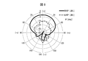
上記実施例1〜4、および上記比較例のそれぞれについて、GPSアンテナの動作周波数である1575.42MHzにおける、第2のアンテナ120(GPSアンテナ)の放射パターンを測定した。図8〜10は、1575.42MHzにおける第2のアンテナ120の放射パターンを示すグラフである。それぞれ、統合アンテナ装置100を上方から見たときに、第2のアンテナ120の中心を通り、且つ、第2のアンテナ120の上辺および下辺と平行なxz面における、右旋円偏波(RHCP:Right Handed Circularly Polarized Wave)と、左旋円偏波(LHCP:Left Handed Circularly Polarized Wave)とに関する放射パターンを示す。
(Verification 2)
For each of the above Examples 1 to 4 and the above Comparative Example, the radiation pattern of the second antenna 120 (GPS antenna) at 1575.42 MHz, which is the operating frequency of the GPS antenna, was measured. 8 to 10 are graphs showing the radiation pattern of the
図8は、本実施例(比較例)における、第2のアンテナ120の放射パターンを示すグラフである。図8に示すように、第1の遮蔽板130および第2の遮蔽板140を設けない場合、第2のアンテナ120の放射パターンにおいて、最大利得方向に殆ど偏りが生じていない。
FIG. 8 is a graph showing the radiation pattern of the
図9(a)は、本実施例(実施例1)における、第2のアンテナ120の放射パターンを示すグラフである。図9(b)は、本実施例(実施例3)における、第2のアンテナ120の放射パターンを示すグラフである。図9(a)に示すように、第1の遮蔽板130のみを設けた場合、第2のアンテナ120の放射パターンにおいて、最大利得方向に偏りが生じている。一方、図9(b)に示すように、第1の遮蔽板130および第2の遮蔽板140の双方を設けた場合、第2のアンテナ120の放射パターンにおいて、最大利得方向の偏りが殆ど生じない。
FIG. 9A is a graph showing the radiation pattern of the
図10(a)は、本実施例(実施例2)における、第2のアンテナ120の放射パターンを示すグラフである。図10(b)は、本実施例(実施例4)における、第2のアンテナ120の放射パターンを示すグラフである。図10(a)に示すように、スリットを有する第1の遮蔽板130のみを設けた場合、第2のアンテナ120の放射パターンにおいて、最大利得方向に偏りが生じている。一方、図10(b)に示すように、それぞれがスリットを有する、第1の遮蔽板130および第2の遮蔽板140の双方を設けた場合、第2のアンテナ120の放射パターンにおいて、最大利得方向に殆ど偏りが生じない。
FIG. 10A is a graph showing the radiation pattern of the
本実施例により、遮蔽板を設けることにより、良好なアイソレーション特性を得られることが確認された。また、遮蔽板にスリットを設けることにより、特定の周波数帯域において、より良好なアイソレーション特性を得られることが確認された。また、遮蔽板を対称的に設けることにより、円偏波受信用アンテナにおける最大利得方向の傾きを抑制できることが確認された。 According to this example, it was confirmed that good isolation characteristics can be obtained by providing a shielding plate. Further, it was confirmed that better isolation characteristics can be obtained in a specific frequency band by providing a slit in the shielding plate. It was also confirmed that the inclination in the maximum gain direction in the circularly polarized wave receiving antenna can be suppressed by providing the shielding plates symmetrically.
〔付記事項〕
本発明は上述した実施形態に限定されるものではなく、請求項に示した範囲で種々の変更が可能である。すなわち、請求項に示した範囲で適宜変更した技術的手段を組み合わせて得られる実施形態についても本発明の技術的範囲に含まれる。
[Additional Notes]
The present invention is not limited to the above-described embodiments, and various modifications can be made within the scope shown in the claims. That is, embodiments obtained by combining technical means appropriately modified within the scope of the claims are also included in the technical scope of the present invention.
例えば、第1のアンテナ110は、少なくともベースをグラウンドとして使用する逆Fアンテナであればよく、LTE用アンテナ以外のアンテナであってもよい。また、第1のアンテナ110は、少なくとも第2のアンテナ120のアンテナ形成面と同一平面上に放射素子を有していればよく、その構成(例えば、アンテナ基板の形状、アンテナパターンの形状、ベースへの実装方法)は、実施形態に示したものに限らない。
For example, the
また、第2のアンテナ120は、少なくとも円偏波受信用アンテナであればよく、GPS用アンテナおよびSDARSアンテナ以外のアンテナであってもよい。また、第2のアンテナ120は、少なくとも第1のアンテナ110のアンテナ形成面と同一平面上に放射素子を有していればよく、その構成(例えば、アンテナ基板の形状、アンテナパターンの形状、ベースへの実装方法)実施形態に示したものに限らない。
The
本発明は、移動体又は移動端末に搭載されるアンテナ装置として、あるいは、そのようなアンテナ装置に搭載されるアンテナとして、好適に利用することができる。移動体の例としては、自動車、鉄道車両、船舶などが挙げられる。移動端末の例としては、スマートフォン、携帯電話機、PDA、タブレット端末などが挙げられる。 The present invention can be suitably used as an antenna device mounted on a mobile body or a mobile terminal, or as an antenna mounted on such an antenna device. Examples of the moving body include an automobile, a railway vehicle, and a ship. Examples of mobile terminals include smartphones, mobile phones, PDAs, and tablet terminals.
100A 統合アンテナ装置
100B 統合アンテナ装置
100C 統合アンテナ装置
101 ベース
102 支持板
103 支柱
104 支持板
105 支柱
110 第1のアンテナ(逆Fアンテナ)
111 アンテナ基板
112 アンテナパターン
112A 第1の部分(放射素子)
112B 第2の部分(短絡部)
112C 第3の部分(放射素子)
112D 第4の部分(グラウンド)
120 第2のアンテナ(円偏波受信用アンテナ)
121 アンテナ基板
122A アンテナパターン(放射素子)
122B アンテナパターン(無給電素子)
123A アンテナパターン(放射素子)
123B アンテナパターン(無給電素子)
130 第1の遮蔽板
140 第2の遮蔽板
150 第3のアンテナ
100A
111 Antenna substrate 112
112B 2nd part (short-circuit part)
112C Third part (radiating element)
112D Fourth part (ground)
120 Second antenna (circular polarization receiving antenna)
121
122B Antenna pattern (parasitic element)
123A Antenna pattern (radiating element)
123B Antenna pattern (parasitic element)
130
Claims (4)
前記ベースをグラウンドとして使用する逆Fアンテナであって、前記ベースの表面と対向する平面上に放射素子を有する第1のアンテナと、
前記第1のアンテナの放射素子と同一面上に放射素子を有する第2のアンテナと、
前記第1のアンテナと前記第2のアンテナとの間において、前記ベースの表面に立設された第1の遮蔽板と、
を備え、
前記第2のアンテナは、衛星からの円偏波を受信するための円偏波受信用アンテナであり、
前記第2のアンテナの周囲には、前記第1の遮蔽板と、前記ベースの表面に立設された第2の遮蔽板とが、前記第2のアンテナを間に挟んで、互いに対称的な位置に配置され、
前記第1のアンテナの放射素子は、前記ベースの表面と対向する平面上に設けられる第1の部分と、前記第1の部分と前記ベースとに交わる第2の部分と、前記第1の部分と交わり、且つ前記ベースと交わらない第3の部分と、を含み、
前記第3の部分は、前記第1の部分の、前記第1の遮蔽板および前記第2の遮蔽板の配置側とは反対側の縁部と連結されていることを特徴とするアンテナ装置。 Base and
An inverted-F antenna using the base as a ground, the first antenna having a radiating element on a plane facing the surface of the base;
A second antenna having a radiating element on the same plane as the radiating element of the first antenna;
A first shielding plate erected on the surface of the base between the first antenna and the second antenna;
Equipped with a,
The second antenna is a circularly polarized wave receiving antenna for receiving circularly polarized waves from a satellite;
Around the second antenna, the first shielding plate and the second shielding plate erected on the surface of the base are symmetrical with each other with the second antenna interposed therebetween. Placed in position,
The radiating element of the first antenna includes a first portion provided on a plane facing the surface of the base, a second portion intersecting the first portion and the base, and the first portion. And a third portion that does not intersect with the base,
Said third portion, said first portion, the antenna device characterized that you have been connected to the edge opposite to the arrangement side of the first shielding plate and the second shielding plate.
前記第3のアンテナは、逆Fアンテナであり、
前記第2の遮蔽板は、
前記第2のアンテナと前記第3のアンテナとの間において、前記ベースの表面に立設されている
ことを特徴とする請求項1に記載のアンテナ装置。 A third antenna having a radiating element on the same plane as the radiating element of the first antenna and the radiating element of the second antenna;
The third antenna is an inverted F antenna;
The second shielding plate is
The antenna device according to claim 1 , wherein the antenna device is erected on a surface of the base between the second antenna and the third antenna.
前記第1のアンテナの放射素子および前記第2のアンテナの放射素子との同一面の高さ以上である
ことを特徴とする請求項1または2に記載のアンテナ装置。 The height position of the upper end of the first shielding plate is
The antenna device according to claim 1 or 2, characterized in that at least the height of the same surface of said first antenna radiation element and the radiating element of the second antenna.
ことを特徴とする請求項1から3のいずれか一項に記載のアンテナ装置。 The slit which was notched in the direction which crosses the surface of the said base in the said 1st shielding board is formed in multiple numbers along the surface of the said base. The any one of Claim 1 to 3 characterized by the above-mentioned. The antenna device according to one item.
Priority Applications (1)
| Application Number | Priority Date | Filing Date | Title |
|---|---|---|---|
| JP2013201983A JP6181498B2 (en) | 2013-09-27 | 2013-09-27 | Antenna device |
Applications Claiming Priority (1)
| Application Number | Priority Date | Filing Date | Title |
|---|---|---|---|
| JP2013201983A JP6181498B2 (en) | 2013-09-27 | 2013-09-27 | Antenna device |
Publications (2)
| Publication Number | Publication Date |
|---|---|
| JP2015070408A JP2015070408A (en) | 2015-04-13 |
| JP6181498B2 true JP6181498B2 (en) | 2017-08-16 |
Family
ID=52836714
Family Applications (1)
| Application Number | Title | Priority Date | Filing Date |
|---|---|---|---|
| JP2013201983A Expired - Fee Related JP6181498B2 (en) | 2013-09-27 | 2013-09-27 | Antenna device |
Country Status (1)
| Country | Link |
|---|---|
| JP (1) | JP6181498B2 (en) |
Families Citing this family (4)
| Publication number | Priority date | Publication date | Assignee | Title |
|---|---|---|---|---|
| JP2017126837A (en) * | 2016-01-12 | 2017-07-20 | 原田工業株式会社 | Composite antenna device |
| JP7224716B2 (en) | 2017-03-29 | 2023-02-20 | 株式会社ヨコオ | antenna device |
| JP7203883B2 (en) * | 2021-03-31 | 2023-01-13 | 原田工業株式会社 | Composite antenna device |
| JP7311078B1 (en) * | 2022-01-12 | 2023-07-19 | 三菱電機株式会社 | antenna device |
Family Cites Families (4)
| Publication number | Priority date | Publication date | Assignee | Title |
|---|---|---|---|---|
| US7079083B2 (en) * | 2004-11-30 | 2006-07-18 | Kathrein-Werke Kg | Antenna, in particular a mobile radio antenna |
| US8462071B1 (en) * | 2010-05-26 | 2013-06-11 | Exelis Inc. | Impedance matching mechanism for phased array antennas |
| WO2012011796A1 (en) * | 2010-07-19 | 2012-01-26 | Laird Technologies, Inc. | Multiple-antenna systems with enhanced isolation and directivity |
| JP5464126B2 (en) * | 2010-11-09 | 2014-04-09 | 日立金属株式会社 | Base station antenna for mobile communication and base station antenna system for mobile communication |
-
2013
- 2013-09-27 JP JP2013201983A patent/JP6181498B2/en not_active Expired - Fee Related
Also Published As
| Publication number | Publication date |
|---|---|
| JP2015070408A (en) | 2015-04-13 |
Similar Documents
| Publication | Publication Date | Title |
|---|---|---|
| JP4121424B2 (en) | Dual polarized antenna | |
| JP6528748B2 (en) | Antenna device | |
| US11196175B2 (en) | Antenna device | |
| US10727589B2 (en) | Antenna device | |
| US8674884B2 (en) | Dual-band circularly polarized antenna | |
| JP5628453B2 (en) | antenna | |
| JP2018121143A (en) | Composite antenna device | |
| JP2022022348A (en) | Slot-equipped patch antenna | |
| JP6181498B2 (en) | Antenna device | |
| JP6825013B2 (en) | Vehicle antenna | |
| JP2020096390A (en) | Antenna device | |
| JP2011077827A (en) | Antenna device | |
| JP2007336296A (en) | Plane type antenna | |
| JP5314610B2 (en) | Compound antenna device | |
| JPWO2014133155A1 (en) | Integrated antenna and manufacturing method thereof | |
| JP5767578B2 (en) | Antenna device | |
| JP2017139686A (en) | Antenna and base station | |
| JP2007124016A (en) | Integrated antenna | |
| JP5837452B2 (en) | Antenna device | |
| JP2013175895A (en) | Antenna | |
| JP2010171507A (en) | In-vehicle composite antenna | |
| JP2011015329A (en) | Integrated antenna | |
| JP2017103709A (en) | Satellite wave reception antenna device | |
| JP5663117B2 (en) | Inverted F type antenna | |
| JP2014011692A (en) | Integrated antenna device |
Legal Events
| Date | Code | Title | Description |
|---|---|---|---|
| A621 | Written request for application examination |
Free format text: JAPANESE INTERMEDIATE CODE: A621 Effective date: 20160526 |
|
| A977 | Report on retrieval |
Free format text: JAPANESE INTERMEDIATE CODE: A971007 Effective date: 20170216 |
|
| A131 | Notification of reasons for refusal |
Free format text: JAPANESE INTERMEDIATE CODE: A131 Effective date: 20170221 |
|
| A521 | Request for written amendment filed |
Free format text: JAPANESE INTERMEDIATE CODE: A523 Effective date: 20170424 |
|
| TRDD | Decision of grant or rejection written | ||
| A01 | Written decision to grant a patent or to grant a registration (utility model) |
Free format text: JAPANESE INTERMEDIATE CODE: A01 Effective date: 20170704 |
|
| A61 | First payment of annual fees (during grant procedure) |
Free format text: JAPANESE INTERMEDIATE CODE: A61 Effective date: 20170720 |
|
| R151 | Written notification of patent or utility model registration |
Ref document number: 6181498 Country of ref document: JP Free format text: JAPANESE INTERMEDIATE CODE: R151 |
|
| R250 | Receipt of annual fees |
Free format text: JAPANESE INTERMEDIATE CODE: R250 |
|
| LAPS | Cancellation because of no payment of annual fees |