JP6181002B2 - Stator and brushless motor - Google Patents
Stator and brushless motor Download PDFInfo
- Publication number
- JP6181002B2 JP6181002B2 JP2014122328A JP2014122328A JP6181002B2 JP 6181002 B2 JP6181002 B2 JP 6181002B2 JP 2014122328 A JP2014122328 A JP 2014122328A JP 2014122328 A JP2014122328 A JP 2014122328A JP 6181002 B2 JP6181002 B2 JP 6181002B2
- Authority
- JP
- Japan
- Prior art keywords
- outer peripheral
- conducting wire
- bobbin
- conductive
- groove
- Prior art date
- Legal status (The legal status is an assumption and is not a legal conclusion. Google has not performed a legal analysis and makes no representation as to the accuracy of the status listed.)
- Active
Links
Images


Classifications
-
- H—ELECTRICITY
- H02—GENERATION; CONVERSION OR DISTRIBUTION OF ELECTRIC POWER
- H02K—DYNAMO-ELECTRIC MACHINES
- H02K3/00—Details of windings
- H02K3/04—Windings characterised by the conductor shape, form or construction, e.g. with bar conductors
- H02K3/28—Layout of windings or of connections between windings
-
- H—ELECTRICITY
- H02—GENERATION; CONVERSION OR DISTRIBUTION OF ELECTRIC POWER
- H02K—DYNAMO-ELECTRIC MACHINES
- H02K1/00—Details of the magnetic circuit
- H02K1/06—Details of the magnetic circuit characterised by the shape, form or construction
- H02K1/12—Stationary parts of the magnetic circuit
- H02K1/14—Stator cores with salient poles
- H02K1/146—Stator cores with salient poles consisting of a generally annular yoke with salient poles
-
- H—ELECTRICITY
- H02—GENERATION; CONVERSION OR DISTRIBUTION OF ELECTRIC POWER
- H02K—DYNAMO-ELECTRIC MACHINES
- H02K1/00—Details of the magnetic circuit
- H02K1/06—Details of the magnetic circuit characterised by the shape, form or construction
- H02K1/22—Rotating parts of the magnetic circuit
- H02K1/27—Rotor cores with permanent magnets
- H02K1/2706—Inner rotors
-
- H—ELECTRICITY
- H02—GENERATION; CONVERSION OR DISTRIBUTION OF ELECTRIC POWER
- H02K—DYNAMO-ELECTRIC MACHINES
- H02K15/00—Methods or apparatus specially adapted for manufacturing, assembling, maintaining or repairing of dynamo-electric machines
- H02K15/08—Forming windings by laying conductors into or around core parts
- H02K15/095—Forming windings by laying conductors into or around core parts by laying conductors around salient poles
-
- H—ELECTRICITY
- H02—GENERATION; CONVERSION OR DISTRIBUTION OF ELECTRIC POWER
- H02K—DYNAMO-ELECTRIC MACHINES
- H02K3/00—Details of windings
- H02K3/46—Fastening of windings on the stator or rotor structure
- H02K3/52—Fastening salient pole windings or connections thereto
- H02K3/521—Fastening salient pole windings or connections thereto applicable to stators only
- H02K3/522—Fastening salient pole windings or connections thereto applicable to stators only for generally annular cores with salient poles
-
- H—ELECTRICITY
- H02—GENERATION; CONVERSION OR DISTRIBUTION OF ELECTRIC POWER
- H02K—DYNAMO-ELECTRIC MACHINES
- H02K5/00—Casings; Enclosures; Supports
- H02K5/04—Casings or enclosures characterised by the shape, form or construction thereof
- H02K5/12—Casings or enclosures characterised by the shape, form or construction thereof specially adapted for operating in liquid or gas
-
- H—ELECTRICITY
- H02—GENERATION; CONVERSION OR DISTRIBUTION OF ELECTRIC POWER
- H02K—DYNAMO-ELECTRIC MACHINES
- H02K2203/00—Specific aspects not provided for in the other groups of this subclass relating to the windings
- H02K2203/06—Machines characterised by the wiring leads, i.e. conducting wires for connecting the winding terminations
Description
本明細書に開示の技術は、ステータ及びブラシレスモータに関する。 The technology disclosed in this specification relates to a stator and a brushless motor.
特許文献1には、電機子のティースを覆うインシュレータに、導線を巻回することによってコイルを形成する技術が開示されている。コイルは、導線がインシュレータの外周に互いに平行に巻回される第1層と、導線が第1層上において互いに平行に巻回される第2層を含む。 Patent Document 1 discloses a technique for forming a coil by winding a conductive wire around an insulator that covers the armature teeth. The coil includes a first layer in which the conductive wires are wound around the outer periphery of the insulator in parallel with each other, and a second layer in which the conductive wires are wound in parallel with each other on the first layer.
ティースに取り付けられるボビン上に導線を巻回する際には、例えばステータの外壁等のステータの他の部分を避けながら導線を巻回しなければならない。 When winding a conducting wire on a bobbin attached to a tooth, the conducting wire must be wound while avoiding other portions of the stator such as an outer wall of the stator.
本明細書では、ステータの他の部分を避けながら適切に導線を巻き回し得る技術を提供する。 In this specification, the technique which can wind a conducting wire appropriately, avoiding the other part of a stator is provided.
本明細書で開示される技術は、モータに用いられるステータに関する。ステータは、外周部と、複数のティースと、複数のボビンと、複数のコイルと、を備える。外周部は、筒状を有する。複数のティースは、外周部の内周面から内周側に伸びる。複数のティースは、外周部の周方向に間隔を開けて並ぶ。複数のボビンは、複数のティースに取り付けられる。各ボビンは、各ティースの外周部側の第1の端と第1の端の反対側の第2の端との中間位置において、当該ティースの側面を一巡する。複数のコイルは、複数のボビン上に配置されている。複数のボビンのそれぞれは、第1の端側の端において、当該ボビンの外周面のうち、少なくとも互いに対向する一対の面に位置する溝を備える。複数のコイルのそれぞれは、当該コイルの導線がボビン外から溝内に配置される導入部と、導入部に連続して配置されており、ボビンに1又は2回巻回される導線のうち、溝内に隣接して配置される1又は2本の導線を含む調整部と、それぞれがティースの延伸方向に沿って導線が隣接して並ぶ複数の導線層と、を備える。少なくとも互いに対向する一対の面上に配置される複数の導線層の最下の導線層は、調整部に含まれる導線及びボビンの外周面に接触している。複数個のコイルのそれぞれにおいて、少なくとも互いに対向する一対の面上に配置される複数の導線層のうち、奇数層目の導線層では、導線は、第1の端側から第2の端側に向かって順に巻回されており、少なくとも互いに対向する一対の面上に配置される複数層の導線層のうち、偶数層目の導線層では、導線は、第2の端側から第1の端側に向かって順に巻回されている。複数層の導線層のうち、奇数層目の導線層では、第1の端側の端に位置する導線と外周部の内周面とは、半ピッチ離間しており、複数層の導線層のうち、2層目以上の導線層では、ボビンの導入部側の端面上に配置される導線以外の導線は、1層下の導線層の隣接する2本の導線の間に形成される凹部に沿って配置されており、導入部側の端面上に配置される導線は、1つ下の導線層の導線と交差する方向に配置されている。 The technology disclosed in this specification relates to a stator used in a motor. The stator includes an outer peripheral portion, a plurality of teeth, a plurality of bobbins, and a plurality of coils. The outer peripheral portion has a cylindrical shape. The plurality of teeth extend from the inner peripheral surface of the outer peripheral portion toward the inner peripheral side. The plurality of teeth are arranged at intervals in the circumferential direction of the outer peripheral portion. The plurality of bobbins are attached to the plurality of teeth. Each bobbin makes a round of the side surface of the tooth at an intermediate position between the first end on the outer peripheral side of each tooth and the second end opposite to the first end. The plurality of coils are disposed on the plurality of bobbins. Each of the plurality of bobbins includes a groove positioned on at least a pair of surfaces facing each other in the outer peripheral surface of the bobbin at the end on the first end side. Each of the plurality of coils has an introduction portion in which the lead wire of the coil is arranged in the groove from the outside of the bobbin, and is continuously arranged in the introduction portion, and among the conductor wires wound once or twice on the bobbin, The adjustment part containing the 1 or 2 conducting wire arrange | positioned adjacently in a groove | channel, and the several conducting wire layer which each arranges an adjacent conducting wire along the extending | stretching direction of teeth are provided. The lowest conductor layer of the plurality of conductor layers arranged on at least a pair of surfaces facing each other is in contact with the conductor wire included in the adjustment portion and the outer peripheral surface of the bobbin. In each of the plurality of coils, among the plurality of conductor layers arranged on at least a pair of surfaces facing each other, in the odd-numbered conductor layer, the conductor is from the first end side to the second end side. Of the plurality of conductive layers arranged at least on a pair of surfaces facing each other, in the even-numbered conductive layers, the conductive wires are connected to the first end from the second end side. It is wound in order toward the side. Among the plurality of conductive layers, in the odd-numbered conductive layers, the conductive wires located at the end on the first end side and the inner peripheral surface of the outer peripheral portion are separated by a half pitch, Among them, in the second and higher conductive layers, the conductive wires other than the conductive wires arranged on the end surface on the introduction portion side of the bobbin are in a recess formed between two adjacent conductive wires in the lower conductive layer. The conducting wire arranged on the end surface on the introduction portion side is arranged in a direction intersecting with the conducting wire of the next lower conducting wire layer.
溝が形成されているボビンの面上では、偶数層目の導線層は、第2の端から第1の端に向かって巻回されている。この構成では、偶数層目の導線層において、外周部付近の導線を巻回する状況では、巻回すべき導線の第2の端側に隣接する導線が、既に配置されている。このため、外周部付近の導線は、隣接する導線に案内されて、外周部付近に適切に巻回される。この結果、導線あるいは導線を巻回させるための装置が、外周部と干渉することを避けながら巻回することができる。 On the surface of the bobbin where the groove is formed, the even-numbered conductive layer is wound from the second end toward the first end. In this configuration, in the situation where the conductive wire near the outer peripheral portion is wound in the even-numbered conductive wire layer, the conductive wire adjacent to the second end side of the conductive wire to be wound is already arranged. For this reason, the conducting wire in the vicinity of the outer peripheral portion is guided by the adjacent conducting wire and appropriately wound around the outer peripheral portion. As a result, the conducting wire or the device for winding the conducting wire can be wound while avoiding interference with the outer peripheral portion.
一方、溝が形成されているボビンの面上では、奇数層目の導線層は、第1の端から第2の端に向かって巻回されている。この構成では、奇数層目の導線層の導線の巻回を開始する際に、外周部を避けながら巻回する必要がある。上記の構成では、奇数層目の導線層の第1の端側の端に位置する導線は、外周部の内周面と半ピッチだけ離間している。この結果、奇数層目の導線層の第1の端側の端に位置する導線が、外周部の内周面と離間せずに位置する構成と比較して、当該導線を巻回する際に、導線あるいは導線を巻回させるための装置が、外周部に干渉することを回避し得る。 On the other hand, on the surface of the bobbin in which the groove is formed, the odd-numbered conductive layer is wound from the first end toward the second end. In this configuration, when starting to wind the conductors of the odd-numbered conductor layers, it is necessary to wind while avoiding the outer peripheral portion. In said structure, the conducting wire located in the end of the odd-numbered conducting wire layer on the first end side is separated from the inner peripheral surface of the outer peripheral portion by a half pitch. As a result, when winding the conducting wire as compared with the configuration in which the conducting wire located at the end on the first end side of the odd-numbered conducting layer is not separated from the inner peripheral surface of the outer peripheral portion, It can be avoided that the lead wire or the device for winding the lead wire interferes with the outer peripheral portion.
本明細書で開示される技術は、モータに用いられるステータに関する。ステータは、外周部と、複数のティースと、複数のボビンと、複数のコイルと、を備える。外周部は、筒状を有する。複数のティースは、外周部の内周面から内周側に伸びる。複数のティースは、外周部の周方向に間隔を開けて並ぶ。複数のボビンは、複数のティースに取り付けられる。各ボビンは、各ティースの外周部側の第1の端と第1の端の反対側の第2の端との中間位置において、当該ティースの側面を一巡する。複数のコイルは、複数のボビン上に配置されている。複数のボビンのそれぞれは、溝と、拡幅部と、を備える。溝は、第1の端側の端において、当該ボビンの外周面のうち、少なくとも互いに対向する一対の面に位置する。拡幅部は、溝のうち、一対の面の一方に位置する部分において、溝の幅を拡幅する。拡幅部の幅は、導線の線径よりも小さい。複数のコイルのそれぞれは、当該コイルの導線がボビン外から、溝のうち、一対の面の他方に位置する部分に配置される導入部と、導入部に連続して配置されており、ボビンに1又は2回巻回される導線のうち、溝内に配置される1又は2本の導線を含む調整部と、それぞれがティースの延伸方向に沿って導線が隣接して並ぶ複数の導線層と、を備える。少なくとも互いに対向する一対の面上に配置される複数の導線層の最下の導線層は、調整部に含まれる導線及びボビンの外周面に接触している。複数個のコイルのそれぞれにおいて、少なくとも互いに対向する一対の面上に配置される複数の導線層のうち、奇数層目の導線層では、導線は、第1の端側から第2の端側に向かって順に巻回されており、少なくとも互いに対向する一対の面上に配置される複数層の導線層のうち、偶数層目の導線層では、導線は、第2の端側から第1の端側に向かって順に巻回されている。複数層の導線層のうち、2層目以上の導線層では、ボビンの導入部側の端面上に配置される導線以外の導線は、1層下の導線層の隣接する2本の導線の間に形成される凹部に沿って配置されており、導入部側の端面上に配置される導線は、1つ下の導線層の導線と交差する方向に配置されている。 The technology disclosed in this specification relates to a stator used in a motor. The stator includes an outer peripheral portion, a plurality of teeth, a plurality of bobbins, and a plurality of coils. The outer peripheral portion has a cylindrical shape. The plurality of teeth extend from the inner peripheral surface of the outer peripheral portion toward the inner peripheral side. The plurality of teeth are arranged at intervals in the circumferential direction of the outer peripheral portion. The plurality of bobbins are attached to the plurality of teeth. Each bobbin makes a round of the side surface of the tooth at an intermediate position between the first end on the outer peripheral side of each tooth and the second end opposite to the first end. The plurality of coils are disposed on the plurality of bobbins. Each of the plurality of bobbins includes a groove and a widened portion. The grooves are located on at least a pair of surfaces that face each other on the outer peripheral surface of the bobbin at the end on the first end side. The widened portion widens the width of the groove in a portion of the groove located on one of the pair of surfaces. The width of the widened portion is smaller than the wire diameter of the conducting wire. Each of the plurality of coils is arranged continuously from the outside of the bobbin to the portion of the groove that is located on the other of the pair of surfaces, and the introduction portion. Of the conducting wires wound once or twice, an adjustment portion including one or two conducting wires arranged in the groove, and a plurality of conducting layers each of which is arranged adjacent to each other along the extending direction of the teeth . The lowest conductor layer of the plurality of conductor layers arranged on at least a pair of surfaces facing each other is in contact with the conductor wire included in the adjustment portion and the outer peripheral surface of the bobbin. In each of the plurality of coils, among the plurality of conductor layers arranged on at least a pair of surfaces facing each other, in the odd-numbered conductor layer, the conductor is from the first end side to the second end side. Of the plurality of conductive layers arranged at least on a pair of surfaces facing each other, in the even-numbered conductive layers, the conductive wires are connected to the first end from the second end side. It is wound in order toward the side. Among the plurality of conductor layers, in the conductor layers of the second and higher layers, the conductors other than the conductor arranged on the end surface on the bobbin introducing portion side are between two adjacent conductors in the conductor layer one layer below. The conducting wire arranged on the end surface on the introduction portion side is arranged in a direction intersecting with the conducting wire of the next lower conducting wire layer.
以下に説明する実施例の主要な特徴を列記する。なお、以下に記載する技術要素は、それぞれ独立した技術要素であって、単独であるいは各種の組合せによって技術的有用性を発揮するものである。 The main features of the embodiments described below are listed. Note that the technical elements described below are independent technical elements, and exhibit technical usefulness alone or in various combinations.
(特徴1)ステータでは、1層目の導線層において、最初に巻回される特定の導線は、調整部に巻き回されている導線に沿って配置されていてもよい。この構成によれば、1層目の導線層の導線のうち、最初に巻回される導線を適切に位置決めすることができる。この結果、1層目の導線層の導線が乱れることを抑制することができる。 (Feature 1) In the stator, in the first conductor layer, the specific conductor wound first may be arranged along the conductor wound around the adjusting portion. According to this structure, the conducting wire wound first among the conducting wires of the 1st conducting wire layer can be positioned appropriately. As a result, it is possible to prevent the conductor of the first conductor layer from being disturbed.
(特徴2)ステータにおいて、調整部では、導線は、溝を形成する側壁に隣接して、1回巻回されていてもよい。1層目の導線層のうち、最初に巻回される特定の導線は、調整部に巻回されている導線と側壁の上端との間に沿って配置されていてもよい。この構成によれば、調整部の導線と溝の側壁とによって、1層目の導線層の導線のうち、最初に巻回される導線を適切に位置決めすることができる。この結果、1層目の導線層の導線が乱れることを抑制することができる。 (Feature 2) In the stator, in the adjustment portion, the conducting wire may be wound once adjacent to the side wall forming the groove. Among the first conductive layer, the specific conductive wire wound first may be arranged between the conductive wire wound around the adjusting portion and the upper end of the side wall. According to this structure, the conducting wire wound first among the conducting wires of the first conducting wire layer can be appropriately positioned by the conducting wire of the adjusting portion and the side wall of the groove. As a result, it is possible to prevent the conductor of the first conductor layer from being disturbed.
(特徴3)ステータにおいて、調整部では、導線は、隣接して2本配置されていてもよい。第2の端側に位置する導線は、溝を形成する側壁に隣接していてもよい。1層目の導線層のうち、最初に巻回される導線は、調整部の導線と側壁の上端との間に沿って配置されていてもよい。この構成によれば、調整部の導線と溝の側壁とによって、1層目の導線層の導線のうち、最初に巻回される導線を適切に位置決めすることができる。この結果、1層目の導線層の導線が乱れることを抑制することができる。 (Characteristic 3) In the stator, two conductors may be arranged adjacent to each other in the adjustment portion. The conducting wire located on the second end side may be adjacent to the side wall forming the groove. Of the first conductor layer, the conductor wound first may be disposed between the conductor of the adjustment unit and the upper end of the side wall. According to this structure, the conducting wire wound first among the conducting wires of the first conducting wire layer can be appropriately positioned by the conducting wire of the adjusting portion and the side wall of the groove. As a result, it is possible to prevent the conductor of the first conductor layer from being disturbed.
(特徴4)ステータにおいて、調整部では、導線は、隣接して2本配置されていてもよい。1層目の導線層のうち、最初に巻回される特定の導線は、調整部の隣接する導線の間に形成される凹部に沿って巻き回されていてもよい。この構成によれば、調整部の隣接する導線によって、1層目の導線層の導線のうち、最初に巻回される導線を適切に位置決めすることができる。この結果、1層目の導線層の導線が乱れることを抑制することができる。 (Feature 4) In the stator, two wires may be arranged adjacent to each other in the adjustment portion. Of the first conductive layer, the specific conductive wire that is wound first may be wound along a recess formed between the adjacent conductive wires of the adjustment unit. According to this structure, the conducting wire wound first can be appropriately positioned among the conducting wires of the first conducting layer by the conducting wires adjacent to the adjustment unit. As a result, it is possible to prevent the conductor of the first conductor layer from being disturbed.
(特徴5)ステータにおいて、奇数層目の導線層の第1の端側の端に位置する導線と外周部の内周面とは、半ピッチ離間しており、偶数層の導線層の第1の端側の端に位置する導線は、外周部の内周面に当接していてもよい。この構成によれば、導線の巻回回数を多くすることができる。 (Characteristic 5) In the stator, the conductive wire located at the first end side of the odd-numbered conductive layer and the inner peripheral surface of the outer peripheral portion are separated by a half pitch, and the first of the even-numbered conductive layers. The conducting wire located at the end of the end may be in contact with the inner peripheral surface of the outer peripheral portion. According to this configuration, the number of windings of the conducting wire can be increased.
(特徴6)ステータにおいて、溝は、第1の端側の端において、当該ボビンの外周面を一巡してもよい。この構成によれば、偶数層目の導線層において、外周部付近の導線を巻回する状況では、巻回すべき導線の第2の端側に隣接する導線が、既に、ボビンを一巡して配置されている。このため、外周部付近の導線は、隣接する導線に、ボビンの全周に亘って案内されて、外周部付近に適切に巻回される。これにより、導線を適切に、第1の端側に配置することができる。 (Feature 6) In the stator, the groove may make a round of the outer peripheral surface of the bobbin at the end on the first end side. According to this configuration, in the situation where the conductor wire near the outer peripheral portion is wound in the even-numbered conductor layer, the conductor wire adjacent to the second end side of the conductor wire to be wound is already arranged around the bobbin. Has been. For this reason, the conducting wire in the vicinity of the outer peripheral portion is guided over the entire circumference of the bobbin by the adjacent conducting wire and appropriately wound around the outer peripheral portion. Thereby, a conducting wire can be appropriately arranged on the first end side.
(特徴7)上記のステータを備えるモータ及び当該モータを備えるポンプも新規で有用である。 (Feature 7) A motor including the stator and a pump including the motor are also novel and useful.
(特徴8)ステータでは、溝は、ボビンの外周面のうち、少なくとも、外周部の軸方向に伸びる一対の面に位置していてもよい。複数のボビンのそれぞれは、溝のうち、一対の面の一方に位置する部分において、溝の幅を拡幅する拡幅部を備えていてもよい。拡幅部の幅は、導線の線径よりも小さくてもよい。導入部は、溝のうち、一対の面の他方に位置する部分に配置されていてもよい。この構成よると、調整部上に巻回される導線が調整部上から脱落することを抑制することができる。 (Feature 8) In the stator, the groove may be located on at least a pair of surfaces extending in the axial direction of the outer peripheral portion of the outer peripheral surface of the bobbin. Each of the plurality of bobbins may include a widened portion that widens the width of the groove in a portion of the groove located on one of the pair of surfaces. The width of the widened portion may be smaller than the wire diameter of the conducting wire. The introduction portion may be disposed in a portion of the groove located on the other of the pair of surfaces. According to this structure, it can suppress that the conducting wire wound on an adjustment part falls off from an adjustment part.
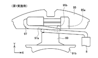
(第1実施例)
図1に示すように、本実施例のステータ60及びモータ部50は、燃料ポンプ10に用いられる。燃料ポンプ10は、燃料タンク(図示省略)内に配置され、自動車等の車両のエンジン(図示省略)に燃料(例えばガソリン等)を供給する。図1に示すように、燃料ポンプ10は、モータ部50の他に、ポンプ部30を備える。モータ部50とポンプ部30は、ハウジング2内に配置されている。ハウジング2は、両端が開口された円筒形状を有する。
(First embodiment)
As shown in FIG. 1, the
ポンプ部30は、ケーシング32とインペラ34を備える。ケーシング32は、ハウジング2の下端の開口を閉塞する。ケーシング32の下端には、吸入口38が設けられている。ケーシング32の上端には、ケーシング32内とモータ部50とを連通する連通孔(図示省略)が設けられている。ケーシング32内には、インペラ34が収容されている。
The
モータ部50は、ポンプ部30の上方に位置する。モータ部50は、ブラシレスモータであり、三相モータである。モータ部50は、ロータ54と、ステータ60と、ターミナル70と、を備える。ロータ54は、永久磁石を備える。ロータ54の中心には、シャフト52が貫通して固定されている。シャフト52の下端は、インペラ34の中心部に挿入され、貫通している。ロータ54は、シャフト52の両端部に配置された軸受けによって、シャフトを中心に回転可能に支持されている。なお実施例では、図1の状態で上下を規定する。即ち、モータ部50から見てポンプ部30は「下」に位置し、ポンプ部30から見てモータ部50は「上」に位置する。
The
ステータ60は、樹脂層66に覆われている。樹脂層66は、ハウジング2の上端の開口を閉塞する。樹脂層66の上端には、吐出口11が形成されている。吐出口11は、モータ部50と燃料ポンプ10外の燃料経路とを連通する。吐出口11は、ポンプ部30で昇圧された燃料を、燃料経路に吐出するための開口である。樹脂層66では、ステータ60を覆う部分と吐出口11とが、樹脂で一体成形されている。なお、ステータ60を覆う部分と吐出口11とは、別体で構成されていてもよい。
The
ステータ60は、コア本体90と、コア本体90に配置される複数(本実施例では6個)のコイル96とを備える。ステータ60の上端には、ターミナル70が取付けられている。ターミナル70は、制御回路を介してバッテリ(ともに図示省略)に接続される。ターミナル70は、ステータ60のコイル96に電力を供給するための端子である。
The
コア本体90は、コアプレート群(92,92,・)と、コアプレート群(92,92,・)の表面に設けられたインシュレータ94と、を備える。コアプレート群(92,92、・)は、複数枚のコアプレート92によって構成されている。なお、図1では、見易さを優先して、複数枚のコアプレート92の断面を示すハッチングは省略されている。複数枚のコアプレート92は上下方向に積層されており、各コアプレート92は磁性体材料によって形成されている。インシュレータ94は、絶縁性の樹脂材料によって形成されている。インシュレータ94は、積層された複数枚のコアプレート92からなるコアプレート群(92,92・・)の表面を覆っている。
The
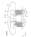
図2に示すように、コア本体90は、6個の部分コアU1,V1,W1,U2,V2,W2を備える。6個の部分コアU1〜W2は、円筒形状に配置されている。6個の部分コアU1〜W2は、2個のU相の部分コアU1,U2と、2個のV相の部分コアV1,V2と、2個のW相の部分コアW1,W2で構成されている。なお、各部分コアU1〜W2は略同一構成であるため、部分コアW1について代表して説明する。
As shown in FIG. 2, the
部分コアW1は、外周部95とティース91(図3参照)とボビン99(図3参照)とを備える。外周部95は、部分コアW1の最も外周側に位置する。外周部95は、コアプレート92の外周部分と、コアプレート92の外周部分を覆うインシュレータ94とによって構成されている。外周部95の外周面は、部分円筒形状を有する。外周部95の内周面は、平板形状を有する。外周部95は、隣接する部分コアU2,V1のそれぞれの外周部95に連結されている。6個の部分コアU1〜W2が、それぞれの外周部95において連結されることにより、筒形状が形成されている。
The partial core W1 includes an outer
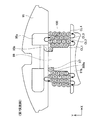
図3に示すように、外周部95の中央部には、ステータ60の中心に向かって伸びるティース91が配置されている。なお、図3では、部分コアW1と、部分コアW1に隣接する部分コアV1,U2が記載されているが、図3に示すコア本体90の展開状態では、6個の部分コアU1〜W2が、部分コアW1,V1,U2に示されるように、直線状に配置されている。
As shown in FIG. 3, a
ティース91は、コアプレート92のうち、外周部95を構成するコアプレート92の外周部分から、外周部95の内周側に伸びる部分によって構成されている。なお、図3では、コアプレート92のうち、部分コアW1に対応する部分のみが記載されているが、実際には、コアプレート92は、6個の部分コアU1〜W2に対応する部分が連結されている。
The
図2に示すように、6個の部分コアU1〜W2に配置されている6個のティース91は、外周部95の周方向に等間隔に配置されている。図3に示すように、ティース91の中間部分91aは、外周部95から外周部95の内周側(図3の下側)に伸びている。ティース91の内周端は、外周部95の周方向に広がっており、ロータ54の外周面に倣う形状を有する。ティース91は、インシュレータ94によって覆われている。ティース91の内周側の端には、インシュレータ94に覆われている内周部91bが配置されている。
As shown in FIG. 2, the six
ボビン99は、ティース91を覆うインシュレータ94のうち、中間部分91aを覆う部分によって構成されている。ボビン99は、中間部分91aの側面を一巡している。より詳細には、ボビン99は、中間部分91aのうち、外周部95とティース91の内周端との間に位置する4個の面を覆っている。ボビン99の外周面には、導線97を支持するためのガイド99aが配置されている。ガイド99aは、ボビン99の外周面に、凹状に形成されている。ガイド99aは、少なくともボビン99の4個の角部のそれぞれに形成されている。なお、ガイド99aは、ボビン99外周面の全周に亘って形成されていてもよい。ガイド99aは、導線97の外形に倣った形状を有する。
The
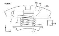
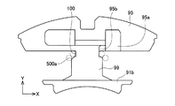
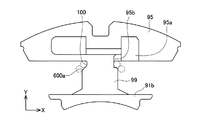
ボビン99の外周部95側の端には、溝100が形成されている。溝100では、ボビン99の外周面が、他の部分のボビン99の外周面よりも凹んでいる。言い換えると、溝100では、ボビン99の外周面が、他の部分のボビン99の外周面よりも、ティース91の近くに位置している。溝100は、ボビン99の外周面の全周に亘って形成されている。このため、溝100が形成されているボビン99の周長は、他の部分のボビン99の周長よりも短い。溝100の幅(即ちステータ60の径方向における溝100の長さ)は、導線97の線径にほぼ等しい。溝100の深さ(即ち溝100の断面において、溝100の幅に垂直方向の長さ)は、導線97の線径にほぼ等しい。
A
図2に示すように、ボビン99には、コイル96が配置されている。コイル96は、導線97がボビン99に巻回されることによって作製されている。コイル96は、端子70に電気的に接続されている。部分コアW1のコイル96は、部分コアW2のコイル96と接続されており、部分コアW1のコイル96及び部分コアW2のコイル96には、同位相の電位が供給される。同様に、部分コアU1のコイル96は、部分コアU2のコイル96と接続されており、部分コアU1のコイル96及び部分コアU2のコイル96には、同位相の電位が供給される。さらに、同様に、部分コアV1のコイル96は、部分コアV2のコイル96と接続されており、部分コアV1のコイル96及び部分コアV2のコイル96には、同位相の電位が供給される。
As shown in FIG. 2, a
(導線の巻回方法)
次に、図4〜10を参照して、導線97を巻回して、コイル96を作製する方法を説明する。導線97は、図3に示すように、部分コアU1〜W2が、直線状に並んだ状態で巻回される。なお、図4以降の図面では、図面の見易さを優先して、ボビン99に形成されているガイド99aを省略する等、簡略化して記載する。導線97は、図4から図9の順に巻回される。なお、図7は、図6に示される状態と同じタイミングにおける導線97の巻回状態を示す図であり、図6が部分コアW1の上方から見ているのに対して、部分コアW1の下方から見た図である。図10は、コイル96が作製された後の状態を示しており、導線97は、ボビン99の上面の位置における断面で示されている。
(Wire winding method)
Next, with reference to FIGS. 4 to 10, a method for producing the
図4に示すように、最初に、導線97の一端を、外周部95の上端に位置する係止部95aに係止する。なお、導線97は、巻回装置8から供給される。そして、係止部95aに係止された導線97を、ボビン99の左側からボビン99の上面を超えて、ボビン99の右側まで引く。次いで、図5に示すように、巻回装置8を、ボビン99の周方向に移動させて、導線97を溝100内に巻回する。
As shown in FIG. 4, first, one end of the
この結果、図5に示すように、導線97は、係止部95aから溝100までの導入部97aを経て、溝100内に配置される。より詳細には、導線97は、導入部97aから、外周部95に形成された拡張部95bを介して、溝100内に導入される。拡張部95bは、溝100の幅を、外周部95側に拡張している。拡張部95bは、溝100の幅が下方に向かって徐々に小さくなるように形成されている。言い換えると、ロータ60の径方向の拡張部95bの長さは、下方の向かうに従って徐々に短くなっている。そして、拡張部95bは、溝100の上下方向の中央位置において消滅する。拡張部95bは、導線97をボビン99に巻回する際に、導入部97aの導線97が干渉することを抑制するために設けられている。従って、拡張部95b内の導線97は、導線97をボビン99に巻回している間に、導線97に押されて、Y軸方向に移動する場合がある。
As a result, as shown in FIG. 5, the
図5の状態から、さらに、巻回装置8をボビン99の周方向に移動させるとともに、Y軸に沿った導線97の進行に合わせて、Y軸に平行に内周部91bに向かって移動させる。これにより、図6,7に示すように、調整部97bと1層目の導線層CL1とが形成される。調整部97bは、溝100内において、導線97が1回だけ巻回されることによって形成される。導線層CL1では、ボビン99の外周部95側の端から反対側の端に向かって、導線97が密に、即ち、隣接して巻回されている。即ち、コイル96のピッチは、導線97の線径に等しい。詳細には、導線層CL1のボビン99の外周部95側の端の導線97は、調整部97bの導線97と溝100の側面とよって形成される凹部(図10の凹部X1参照)に沿って巻回されている。この構成によれば、導線層CL1の導線97のうち、最初に巻回される導線97を適切に位置決めすることができる。この結果、以降に巻回される導線層CL1の導線97が乱れることを抑制することができる。導線層CL1のボビン99の外周部95側の端の導線97(即ち、図10の導線C3,C4)は、外周部95の内周面から、略半ピッチ(即ち、導線97の線径の1/2の長さ)だけ離間している。一方、導線層CL1のボビン99内周部91b側の端の導線97(即ち、図10の導線C11,C12)は、内周部91bに当接している。
From the state of FIG. 5, the winding
図6,7を比較して明らかなように、第1層目の導線層CL1では、ボビン99の上端面上に配置される導線97は、X軸に対して傾斜している一方、ボビン99の下端面上に配置される導線97は、導線97の進行方向(即ちY軸方向)に対して垂直(即ちX軸方向に平行)に巻回されている。
6 and 7, in the first conductor layer CL1, the
続いて、巻回装置8を、ボビン99の周方向に移動させるとともに、Y軸に沿った導線97の進行に合わせて、内周部91bから外周部95に向かって移動させる。この結果、図8に示すように、2層目の導線層CL2が形成される。導線層CL2では、ボビン99の内周部91b側の端から外周部95側の端に向かって、導線97が密に巻回されている。詳細には、導線層CL2では、内周部91b側の端の導線97(即ち図10の導線C11,C12)は、内周部91bに当接しており、外周部95側の端の導線97(即ち図10の導線C19,C20)は、外周部95に当接している。また、導線層CL2のうちの両端の導線97(即ち図10の導線C13〜C18)は、導線層CL1の導線97の間に形成される凹部に沿って巻回されている。
Subsequently, the winding
図8に示すように、外周部95側の端の導線97(即ち図10の導線C19,C20)を巻回する際には、導線97を、外周部95側の端の導線97の1巻前の導線97(即ち図10の導線C17,C18)に接触させながら巻回する。より詳細には、図10の導線C21に示される位置に導線97を配置して巻回すると、導線97は、導線C17に沿って滑り落ちて、導線C19の位置に収まる。このため、巻回装置8を、外周部95に当接する程度に、外周部95に近づけなくても巻回することができる。
As shown in FIG. 8, when winding the
また、導線層CL2では、ボビン99の上端面上に配置される導線97は、X軸に対して導線97のY軸に沿った進行方向に傾斜している一方、ボビン99の下端面上に配置される導線97は、X軸に平行に巻回されている。ボビン99の上端面上に配置される導線97は、導線層CL1の導線97と交差するように傾斜している。
Also, in the conductor layer CL2, the
次いで、図8の状態から、3層目の導線層CL3(図10参照)を形成するために、巻回装置8をボビン99の周方向に移動させる。この結果、導線層CL3の外周部95側の端に巻回される導線97(即ち図10の導線C21,C22)は、導線層CL2の外周部95側の端から2巻巻回されている導線97(図10の導線C17〜C20)によって形成される凹部X2に沿って巻回される。
Next, from the state of FIG. 8, the winding
この結果、導線層CL3のボビン99の外周部95側の端の導線97(即ち図10の導線C21,C22)は、外周部95の内周面から、略半ピッチだけ離間している。この構成によれば、巻回装置8を、外周部95に当接する程度に、外周部95に近づけなくても巻回することができる。
As a result, the
図9の状態から、巻回装置8を、ボビン99の周方向及び外周部95と内周部91bとの間で移動させて、導線層CL3、CL4を形成することによって、コイル96が作製される。なお、コイル96の導線97の端は、部分コアW2に配置されているコイル96の導線97に接続される。同様に、部分コアU1のコイル96の導線97の端は、部分コアU2に配置されているコイル96の導線97に接続され、部分コアV1のコイル96の導線97の端は、部分コアV2に配置されているコイル96の導線97に接続される。
From the state of FIG. 9, the
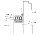
図10に示すように、コイル96では、奇数層の導線層CL1、CL3では、導線C3,C4,C21,C22は、外周部95の内周面から導線97の線径の1/2だけ離間している。一方、偶数層の導線層CL2、CL4では、導線C19,C20,C37は、外周部95の内周面に当接している。なお、変形例では、コイル96は、5層以上の導線層が巻回されていてもよい。本変形例でも、奇数層の導線層CL1、CL3・・・では、導線は、外周部95の内周面から導線97の線径の1/2だけ離間し、偶数層の導線層CL2、CL4・・・では、導線は、外周部95の内周面に当接していてもよい。
As shown in FIG. 10, in the
(本実施例の効果)
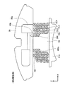
図11,12に記載されている比較例と比較して、本実施例の効果を説明する。比較例では、ボビン199に溝100は形成されておらず、外周部95側の端から内周部91b側の端まで同一の周長を有する。この比較例では、図12に示すように、1層目の導線層の導線97は、外周部95の内周面に当接する一方、2層目の導線層CL2の導線97は、外周部95の内周面から略半ピッチだけ離間している。この構成では、できる限りコイル96の導線97に密に巻回しようとすると、3層目の導線層CL3では、外周部95側の端の導線97は、外周部95の内周面に当接するように配置する必要がある。
(Effect of this embodiment)
The effect of the present embodiment will be described in comparison with the comparative example described in FIGS. In the comparative example, the
しかしながら、外周部95側の端の導線97は、3層目の導線層CL3の導線97のうち、最初に巻回される導線である。このため、3層目の導線層には、外周部95側の端の導線97を案内するような導線は巻回されていない。外周部95側の端の導線97は、2層目の導線層の外周部95側の端の導線97と、外周部95の内周面と、の間の凹部に沿って巻回される。このため、巻回装置8を、外周部95に近づけた状態で、導線97を巻回しなければならない。また、この状態では、巻回装置8から伸びる導線97を強く引っ張ると、導線97が、2層目の導線層の外周部95側の端の導線97と、外周部95の内周面と、の間の凹部から脱落してしまい、適切に巻回することができない場合がある。
However, the
一方、図10に示すように、本実施例のステータ60では、調整部97bが配置されているために、奇数層の導線層CL1,CL3(即ち、導線C3,C4,C21,C22)は、外周部95の内周面から略半ピッチだけ離間している。このため、比較例のような状況を回避することができる。また、偶数層の導線層CL2,CL4(即ち、導線C19,C20,C37)は、外周部95の内周面に当接しているが、偶数層の導線層CL2,CL4では、導線97は、内周部91bから外周部95に向かって巻回されている。このため、導線C19,C20,C37を巻回する状況では、既に、偶数層の導線層CL2,CL4において、外周部95の内周面に当接する導線97に隣接する導線97(即ち、導線C17,C18,C35)が巻回されている。このため、導線C19,C20,C37は、導線C17,C18,C35に案内されて適切に巻回される。本実施例の構成によれば、導線97を、外周部95に強く接触させることなく、高密度に適切に巻回することができる。
On the other hand, as shown in FIG. 10, in the
また、図12に示す比較例では、3層目の導線層のうち、最初に巻回される導線97を巻回する際に、当該導線97は、導入部97aの導線97と干渉する。このため、導線97を外周部95の内周面に当接するように巻回することが難しい。一方、本実施例では、2層目の導線層CL2のうち、外周部95側の端に巻回される導線97、及び、3層目の導線層CL3のうち、外周部95側の端に巻回される導線97は、図9に示すように、導線層CL2の外周部95側の2本の導線97(図10の導線C17とC19,C18とC20)の間に沿って巻回されるため、巻回時に、導入部97aの導線97によって影響を受けない。本実施例のステータ60によれば、導線97の巻回時に、導線97が導入部97aに当接し、巻き崩れることを回避することができる。
Moreover, in the comparative example shown in FIG. 12, when winding the
(第2実施例)
図13,14を参照して、第1実施例と異なる点を説明する。本実施例は、第1実施例と比較して、溝200の形状が、第1実施例の溝100の形状と異なる。また、本実施例は、第1実施例と比較して、コイル96を構成する導線97の巻回方法が異なる。
(Second embodiment)
Points different from the first embodiment will be described with reference to FIGS. In the present embodiment, the shape of the
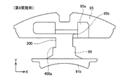
図14に示すように、溝200は、溝100と同様に、ボビン99の外周部95側の端に配置されており、溝200では、ボビン99の外周面が、他の部分のボビン99の外周面よりも凹んでいる。溝200の幅は、導線97の線径の2倍にほぼ等しい。その他の溝200の構成は、溝100の構成と同様である。
As shown in FIG. 14, the
(導線の巻回方法)
図13に示すように、導線97は、第1実施例と同様に、導入部97aを経て、溝200内に配置される。そして、導線97は、溝200内において、2回だけ巻回される。この結果、溝200内には、Y軸方向に隣接する2本の導線97が配置される。図14に示すように、溝200内の導線97は、外周部95aから内周部91bに向かう方向、即ち、導線C1,C2,C3,C4の順に巻回される。これにより、溝200内に、調整部297bが形成される。
(Wire winding method)
As shown in FIG. 13, the
調整部297bが形成されると、続いて、図13の矢印に示されるように、導線97は、調整部297b上に巻回される。この結果、導線層CL1の最初の導線C5,C6が巻回される。導線層C5,C6は、調整部297bの導線C1,C2,C3,C4によって形成される凹部X201に沿って巻回される。この構成によれば、導線層CL1の導線97のうち、最初に巻回される導線97を適切に位置決めすることができる。この結果、以降に巻回される導線層CL1の導線97が乱れることを抑制することができる。なお、この巻回方法では、導線層CL1の導線97のうち、最初に巻回される導線97は、調整部297bを形成する導線97と、ボビン99の上端側で交差する。
If the
続いて、図14に示すように、第1実施例と同様に、導線97が導線層CL1〜CL4まで巻回され、コイル96が作製される。なお、コイル96は、5層以上の導線層によって作製されていてもよい。
Subsequently, as shown in FIG. 14, similarly to the first embodiment, the
本実施例においても、第1実施例と同様の効果を奏することができる。 In this embodiment, the same effect as that of the first embodiment can be obtained.
(第3実施例)
図15〜17を参照して、第2実施例と異なる点を説明する。本実施例は、第2実施例と比較して、コイル96を構成する導線97の巻回方法が異なる。
(Third embodiment)
Points different from the second embodiment will be described with reference to FIGS. This embodiment is different from the second embodiment in the winding method of the
(導線の巻回方法)
図15に示すように、導線97は、第2実施例と同様に、導入部97aを経て、溝200内に配置される。そして、導線97は、溝200内において、2回だけ巻回される。この結果、溝200内には、外周部95aと内周部91bとの方向に隣接する2本の導線97が配置される。図17に示すように、溝200内の導線97は、外周部95aから内周部91bに向かう方向、即ち、導線C1,C2,C3,C4の順に巻回される。これにより、溝200内に、調整部397bが形成される。
(Wire winding method)
As shown in FIG. 15, the
調整部397bが形成されると、続いて、導線97は、導線層CL1のうち、最初に巻回される導線97を、調整部397bの内周部91b側の端の導線97と溝200の側面とよって形成される凹部X301(図17参照)に沿って巻回されている。この構成によれば、導線層CL1の導線97のうち、最初に巻回される導線97を適切に位置決めすることができる。この結果、以降に巻回される導線層CL1の導線97が乱れることを抑制することができる。
When the
続いて、導線97は、内周部91bに向かって巻回される。図16に示すように、導線層CL1の導線97が内周部91bに当接するまで巻回されると(図17の導線C9,C10)、第1,2実施例と同様に、導線層CL2の内周部91b側の端の導線97(図17の導線C11,C12)から順に、導線層CL2が形成される。
Subsequently, the
図17に示すように、導線層CL2の導線C15,C16が巻回されると、次いで、導線97は、調整部397bの導線C1〜C4上に、巻回される。即ち、導線C15,C16が巻回されると、導線層CL1を形成する導線97が巻回される。次いで、導線C5,C6,C17,C18上に、導線層CL2を形成する導線C19,C20が巻回され、次いで、導線C21,C22が巻回される。これにより、導線層CL2が形成される。以降、第1,2実施例と同様に、導線97が巻回されて、導線層CL1〜CL4を有するコイル96が作製される。
As shown in FIG. 17, when the conducting wires C15 and C16 of the conducting wire layer CL2 are wound, the
本実施例においても、第1,2実施例と同様の効果を奏することができる。 In this embodiment, the same effects as in the first and second embodiments can be obtained.
(第4実施例)
上述した各実施例では、溝100は、ボビン99の外周面の全周に亘って形成されている。しかしながら、本実施例では、溝100は、ボビン99の外周面のうち、ティース91の中間部分91aを挟んで対向する一対の面(即ち、上下方向に伸びる一対の面)に形成されていている。この場合、導入部97aの下端は、溝100に配置される導線97に連続している。図21、図22には、ボビン99のうち、上下方向に伸びる一対の面に溝100が形成されている場合の導線97の巻回状態を示す図である。図21は、導線97が、ボビン99の上面の位置における断面で示されており、図22は、導線97が、ボビン99の上面の中央位置において、ボビン99の上面の垂直な断面で示されている。なお、図中の導線97内の数字は、導線97の巻き数を示す。
(Fourth embodiment)
In each embodiment described above, the
図21に示すように、1巻き目(即ち導線97内の数字が「1」)の導線97は、溝100内に配置されている。一方、図22に示すように、溝100が形成されていない面では、1巻き目の導線97は、1層目の最初に巻回される導線に相当する。溝100が設けられている面では、1層目の導線層CL1〜4層目の導線層CL4のそれぞれにおいて、導線97は、4回、5回、4回、5回巻回されている。これに対して、溝100が設けられていない面では、導線層CL1〜導線層CL4のそれぞれにおいて、導線97は、5回、4回、5回、4回巻回されている。
As shown in FIG. 21, the first wire 97 (that is, the number in the
2層目の導線層CL2の外周部95側の端に位置する導線(図21の即ち導線97内の数字が「10」)は、上記した第1〜第3実施例と同様に、隣接する導線(図21の即ち導線97内の数字が「9」)に沿って滑り落ちて、2層目の導線層の外周部95側の端に収まる。図22に示すように、上下方向に伸びる面において、2層目の導線層の外周部95側の端に位置する導線97は、ボビン99の上下端面では、3層目の導線層の外周部95側の端に位置する。この場合であっても、導線97は、上下方向に伸びる面の2層目の導線(図21の即ち導線97内の数字が「9」)によって案内されているため、巻回装置8を、外周部95に当接する程度に、外周部95に近づけなくても巻回することができる。
The conductive wire located at the end of the second conductive layer CL2 on the outer
本実施例においても、第1〜3実施例と同様の効果を奏することができる。 Also in this embodiment, the same effects as those of the first to third embodiments can be obtained.
なお、変形例では、溝100は、ボビン99の外周面のうち、少なくともティース91の中間部分91aを挟んで対向する一対の面のうち、ボビン99の上下端面に形成されていてもよい。この場合、導入部97aの下端は、溝100に配置される導線97に連続していてもよい。
In the modification, the
以上、本発明の実施形態について詳細に説明したが、これらは例示に過ぎず、特許請求の範囲を限定するものではない。特許請求の範囲に記載の技術には、以上に例示した具体例を様々に変形、変更したものが含まれる。 As mentioned above, although embodiment of this invention was described in detail, these are only illustrations and do not limit a claim. The technology described in the claims includes various modifications and changes of the specific examples illustrated above.
(1)上述した各実施例では、ブラシレスモータを燃料ポンプ10に用いた例であったが、本明細書に開示するブラシレスモータは、冷却水ポンプ等の電動ポンプや、他の装置に用いられてもよい。
(1) In each of the above-described embodiments, the brushless motor is used as the
(2)上記した第2実施例では、溝200内の導線97は、外周部95aから内周部91bに向かう方向に順に巻回されている。しかしながら、図18〜20に示すように、調整部297bでは、導入部97aから導線97が溝200に導入されると、溝200を一回巻回する間に、溝200の内周部91b側の端(図18のPで示される位置)に進行していてもよい。続いて、導線97は、ボビン99の上端を、Y軸に平行に配置される。次いで、図19に示すように、導線97が、ボビン99の一方の側面(図18における右側の側面)において交差され、図20に示すように、ボビン99の他方の側面(図18における左側の側面)において平行に配置されるように、巻回されていてもよい。
(2) In the second embodiment described above, the
(3)上述した実施例では、6スロットの3相モータであるモータ部50が記載されているが、モータは、3×N(Nは、正の整数)個のスロットを有する3相の交流モータであってもよい。この場合、3×N個の部分コアが、ステータに含まれていてもよい。そして、3×N個の部分コアは、N個のコアグループに分類されていてもよい。そして、各コアグループに属する3個の部分コアは、ステータの周方向に並んで配置されてよい。1個のコアグループに属する3個の部分コアでは、対向面は、当接していてもよい。一方、コアグループ間に位置する対向面のうちの少なくとも1組の対向面は、間隔を空けて配置されていてもよい。なお、同一のコアグループの隣接する部分コアに含まれる1組の対向面が、間隔を空けて配置されていてもよい。
(3) In the above-described embodiment, the
(第5実施例)
図23,24を参照して、第1実施例と異なる点を説明する。本実施例は、第1実施例と比較して、溝100の一部において、溝100の幅、即ち、溝100のステータ60の径方向(即ちY軸方向)の長さが、第1実施例の溝100の幅よりkだけ長い。kは、0より大きく、導線97の線径よりも細い。これにより、溝100の幅は、W(Wは、溝100に巻回される回数に、導線97の線径Dを乗算した値)+k(0<k<D)となる。例えば、kは、導線97の線径の1/4以上3/4以下であってもよい。
(5th Example)
A difference from the first embodiment will be described with reference to FIGS. In the present embodiment, compared with the first embodiment, in a part of the
具体的には、ボビン99の外周面の全周に亘って形成されている溝100のうち、外周部95の軸方向(即ち図23の紙面垂直方向)に伸びる部分であって、拡張部95bが形成されていない側の部分に、拡幅部100aが配置されている。拡幅部100aは、溝100の外周部95側の端に配置されている。拡幅部100aは、外周部95の内周面に形成されている。拡幅部100aの深さ、即ち、溝100のステータ60の径方向の長さは、上記したkである。また、拡幅部100aの高さ、即ち、外周部95の内周面に平行な方向(即ちX軸方向)の長さは、導線97の線径と略同一である。拡幅部100aは、XY平面に垂直な方向に、ボビン99と同一の長さを有する。なお、変形例では、拡幅部100aは、XY平面に垂直な方向に、ボビン99よりも短くてもよい。
Specifically, in the
図24に示すように、第1実施例と同様の巻回方法を用いて、導線97を巻回させると、導線C2が巻回される段階では、導線C2は、Y軸方向において、導線C1と同じ位置に巻回されている。そして、導線C4が巻回される段階では、導線C4は、導線C2と溝100の側面との間に配置される。このとき、導線C2は、導線C4によって、拡幅部100a側に押圧され、外周部95に当接するまで移動される。これにより、導線C2と溝100の側面との間に、凹部X5が形成される。凹部X5のY軸方向の長さは、上記したkと同一である。導線C4は、凹部X5に嵌った状態で、凹部X5に沿って巻回される。この構成よれば、凹部X5によって、導線C4を、適切に位置決めすることができる。この結果、導線C5以降が巻回される段階で、導線C4が凹部X5から内周部91a側に移動して、導線層CL1の導線97が乱れることを抑制することができる。
As shown in FIG. 24, when the
(第6実施例)
図25,26を参照して、第2実施例と異なる点を説明する。本実施例は、第2実施例と比較して、溝200の一部において、溝200の幅、即ち、溝200のステータ60の径方向(即ちY軸方向)の長さが、第2実施例の溝200の幅よりkだけ長い。kは、0より大きく、導線97の線径よりも細い。例えば、kは、導線97の線径の1/4以上3/4以下であってもよい。
(Sixth embodiment)
Points different from the second embodiment will be described with reference to FIGS. In the present embodiment, compared with the second embodiment, the width of the
具体的には、溝200の外周部95側の端には、拡幅部100aと同様の拡幅部200aが配置されている。図26に示すように、第2実施例と同様の巻回方法を用いて、導線97を巻回させると、導線C1〜C4が巻回される段階では、導線C2,C4のそれぞれは、Y軸方向において、導線C1,C3のそれぞれと同じ位置に巻回されている。そして、導線C6が巻回される段階では、導線C6は、導線C2と導線C4との間に配置される。このとき、導線C2は、導線C6によって、拡幅部100a側に押圧され、外周部95に当接するまで移動される。これにより、導線C2と導線C4との間に、凹部X6が形成される。凹部X6のY軸方向の長さは、上記したkと同一である。導線C6は、凹部X5に嵌った状態で、凹部X5に沿って巻回される。この構成よれば、凹部X5によって、導線C6を、適切に位置決めすることができる。この結果、導線C6以降が巻回される段階で、導線C6が凹部X5から内周部91bに移動して、導線層CL1の導線97が乱れることを抑制することができる。
Specifically, a widened
(第7実施例)
図27,28を参照して、第5実施例と異なる点を説明する。本実施例では、拡幅部300aは、溝100の内周部91b側に配置されている。言い換えると、溝100の幅は、拡幅部300aが形成されている部分において、内周部91b側に、kだけ拡幅されている。拡幅部300aは、XY平面に垂直な方向に、ボビン99と同一の長さを有する。なお、変形例では、拡幅部300aは、XY平面に垂直な方向に、ボビン99よりも短くてもよい。
(Seventh embodiment)
Points different from the fifth embodiment will be described with reference to FIGS. In the present embodiment, the widened
図28に示すように、第1実施例と同様の巻回方法を用いて、導線97を巻回させると、導線C2が巻回される段階では、導線C2は、Y軸方向において、導線C1と同じ位置に巻回されている。そして、導線C4が巻回される段階では、導線C4は、導線C2と溝100の側面との間に形成されている凹部X7に嵌った状態で、凹部X7に沿って巻回される。この構成よれば、凹部X7によって、導線C4を、適切に位置決めすることができる。この結果、導線C7以降が巻回される段階で、導線C4が凹部X7から内周部91bに移動して、導線層CL1の導線97が乱れることを抑制することができる。
As shown in FIG. 28, when the
(第8実施例)
図29,30を参照して、第6実施例と異なる点を説明する。本実施例では、拡幅部400aは、第7実施例との拡幅部300aと同様に、溝200の内周部91a側に配置されている。この構成では、図30に示すように、導線C1〜C4が巻回される段階では、導線C2,C4のそれぞれは、Y軸方向において、導線C1,C3のそれぞれと同じ位置に巻回されている。そして、導線C6が巻回される段階では、導線C6は、導線C2と導線C4との間に配置される。このとき、導線C4は、導線C6によって、内周部91a側に押圧され、拡幅部400aの側面に当接するまで移動される。これにより、導線C2と導線C4との間に、凹部X8が形成される。導線C6は、凹部X8に嵌った状態で、凹部X8に沿って巻回される。この構成よれば、凹部X8によって、導線C6を、適切に位置決めすることができる。この結果、導線C6以降が巻回される段階で、導線C6が凹部X5から内周部91bに移動して、導線層CL1の導線97が乱れることを抑制することができる。
(Eighth embodiment)
The difference from the sixth embodiment will be described with reference to FIGS. In the present embodiment, the widened
以上、本発明の実施形態について詳細に説明したが、これらは例示に過ぎず、特許請求の範囲を限定するものではない。特許請求の範囲に記載の技術には、以上に例示した具体例を様々に変形、変更したものが含まれる。 As mentioned above, although embodiment of this invention was described in detail, these are only illustrations and do not limit a claim. The technology described in the claims includes various modifications and changes of the specific examples illustrated above.
例えば、第7実施例の拡幅部300aは、溝100の深さ(即ちX軸方向の長さ)と同一の深さを有しているが、拡幅部300aの形状は、これに限定されない。例えば、図31に示すように、拡幅部500aの深さは、溝100よりも浅くてもよい。その他の拡幅部500aの形状は、拡幅部300aの形状と同様であってもよい。
For example, the widened
また、例えば、第7実施例の拡幅部300aの幅(即ち、Y軸方向の長さ)は、X軸方向に一定であるが、拡幅部300aの形状は、これに限定されない。例えば、図32に示すように、拡幅部600aの幅は、X軸方向に沿って変化してもよい。例えば、拡幅部600aは、溝100の内周部91b側の側壁を面取りすることによって作製してもよい。
For example, the width (that is, the length in the Y-axis direction) of the widened
さらに、例えば、図33に示すように、ボビン99の溝100を形成する面を、湾曲面700aに形成することによって、拡幅部を形成してもよい。あるいは、図34に示すように、ボビン99の溝100側の端部が、X軸に沿って、拡張部95aが形成されている側から徐々に低くなる傾斜面800aを形成することによって、溝100を拡幅させてもよい。
Further, for example, as shown in FIG. 33, the widened portion may be formed by forming a surface on which the
上記の拡幅部500a〜800aは、一般的に言うと、「拡幅部は、溝のうち、少なくともボビンの外周側の端部(あるいは、ティースの側面から離間している側の端部)の幅を拡幅する」ということができる。また、上記の拡幅部500a〜800aも、「溝のうち、一対の面の他方に位置する部分では、溝の幅が、W(Wは、前記調整部に巻回される回数に、導線の線径Dを乗算した値)+k(0<k<D)である」構成、及び「溝のうち、一対の面の一方に位置する部分において、溝の幅を拡幅する」構成に該当する。なお、拡幅部500a〜800aは、溝200を拡幅するための拡幅部としても適用することが可能である。
Generally speaking, the widened
また、本明細書または図面に説明した技術要素は、単独であるいは各種の組合せによって技術的有用性を発揮するものであり、出願時請求項記載の組合せに限定されるものではない。また、本明細書または図面に例示した技術は複数目的を同時に達成するものであり、そのうちの一つの目的を達成すること自体で技術的有用性を持つものである。 The technical elements described in this specification or the drawings exhibit technical usefulness alone or in various combinations, and are not limited to the combinations described in the claims at the time of filing. In addition, the technology illustrated in the present specification or the drawings achieves a plurality of objects at the same time, and has technical utility by achieving one of the objects.
10:燃料ポンプ、30:ポンプ部、50:モータ部、54:ロータ、60:ステータ、90:コア本体、91:ティース、91a:中間部分、91b:内周部、95:外周部、96:コイル、99:ボビン、U1,V1,W1,U2,V2,W2:部分コア 10: Fuel pump, 30: Pump part, 50: Motor part, 54: Rotor, 60: Stator, 90: Core body, 91: Teeth, 91a: Intermediate part, 91b: Inner peripheral part, 95: Outer peripheral part, 96: Coil, 99: Bobbin, U1, V1, W1, U2, V2, W2: Partial core
Claims (10)
筒状の外周部と、
前記外周部の内周面から内周側に伸びる複数のティースであって、前記外周部の周方向に間隔を開けて並ぶ前記複数のティースと、
前記複数のティースに取り付けられる複数のボビンであって、各ボビンは、各ティースの外周部側の第1の端と前記第1の端の反対側の第2の端との中間位置において、当該ティースの側面を一巡する、前記複数のボビンと、
前記複数のボビン上に配置されている複数のコイルと、を備え、
前記複数のボビンのそれぞれは、前記第1の端側の端において、当該ボビンの外周面のうち、少なくとも互いに対向する一対の面に位置する溝を備え、
前記複数のコイルのそれぞれは、
当該コイルの導線が前記ボビン外から前記溝内に配置される導入部と、
導入部に連続して配置されており、前記ボビンに1又は2回巻回される前記導線のうち、前記溝内に隣接して配置される1又は2本の前記導線を含む調整部と、
それぞれが前記ティースの延伸方向に沿って前記導線が隣接して並ぶ複数の導線層であって、前記少なくとも互いに対向する一対の面上に配置される前記複数の導線層の最下の導線層は、前記調整部に含まれる前記導線及び前記ボビンの前記外周面に接触している、前記複数の導線層と、を備え、
前記少なくとも互いに対向する一対の面上に配置される前記複数個のコイルのそれぞれにおいて、
前記少なくとも互いに対向する一対の面上に配置される前記複数の導線層のうち、奇数層目の導線層では、導線は、前記第1の端側から前記第2の端側に向かって順に巻回されているとともに、前記第1の端側の端に位置する導線と前記外周部の前記内周面とは、半ピッチ離間しており、
前記少なくとも互いに対向する一対の面上に配置される前記複数層の導線層のうち、偶数層目の導線層では、導線は、前記第2の端側から前記第1の端側に向かって順に巻回されており、
前記複数層の導線層のうち、2層目以上の導線層では、前記ボビンの前記導入部側の端面上に配置される導線以外の導線は、1層下の導線層の隣接する2本の導線の間に形成される凹部に沿って配置されており、前記導入部側の端面上に配置される導線は、前記1つ下の導線層の導線と交差する方向に配置されている、ステータ。 A stator used in a motor,
A cylindrical outer periphery;
A plurality of teeth extending from the inner peripheral surface of the outer peripheral portion toward the inner peripheral side, and the plurality of teeth arranged at intervals in the circumferential direction of the outer peripheral portion;
A plurality of bobbins attached to the plurality of teeth, each bobbin being at an intermediate position between a first end on the outer peripheral side of each tooth and a second end opposite to the first end; A plurality of bobbins that go around the side of the teeth;
A plurality of coils disposed on the plurality of bobbins,
Each of the plurality of bobbins includes a groove located on at least a pair of opposite surfaces of the outer peripheral surface of the bobbin at the end on the first end side,
Each of the plurality of coils is
An introduction part in which the conductive wire of the coil is disposed in the groove from the outside of the bobbin;
An adjustment unit including one or two conductors arranged adjacent to each other in the groove among the conductors that are continuously arranged in the introduction part and wound around the bobbin one or two times;
Each of the plurality of conductor layers in which the conductors are arranged adjacent to each other along the extending direction of the teeth, and the lowest conductor layer of the plurality of conductor layers disposed on the pair of surfaces facing each other at least A plurality of conductor layers in contact with the outer circumference of the conductor and the bobbin included in the adjustment unit,
In each of the plurality of coils disposed on at least a pair of surfaces facing each other,
Among the plurality of conductor layers arranged on at least the pair of surfaces facing each other, in the odd-numbered conductor layers, the conductors are wound in order from the first end side toward the second end side. The lead wire positioned at the end on the first end side and the inner peripheral surface of the outer peripheral portion are spaced apart by a half pitch,
Among the plurality of conductive layers arranged on at least a pair of surfaces facing each other, in an even-numbered conductive layer, the conductive wires are sequentially from the second end side toward the first end side. Is wound,
Among the plurality of conductive layers, in the second or more conductive layers, the conductive wires other than the conductive wires arranged on the end surface on the introduction part side of the bobbin are two adjacent conductive layers in the lower layer. The stator is disposed along a recess formed between the conductors, and the conductor disposed on the end surface on the introduction portion side is disposed in a direction intersecting with the conductor of the one lower conductor layer. .
前記複数のボビンのそれぞれは、前記溝のうち、前記一対の面の一方に位置する部分において、前記溝の幅を拡幅する拡幅部であって、前記拡幅部の幅は、前記導線の線径よりも小さい、前記拡幅部を備え、
前記導入部は、前記溝のうち、前記一対の面の他方に位置する部分に配置される、請求項1に記載のステータ。 The groove is located on at least a pair of surfaces extending in the axial direction of the outer peripheral portion of the outer peripheral surface of the bobbin,
Each of the plurality of bobbins is a widened portion that widens the width of the groove in a portion of the groove located on one of the pair of surfaces, and the width of the widened portion is a wire diameter of the conductor. Smaller than the widened portion,
The stator according to claim 1, wherein the introduction portion is disposed in a portion of the groove located on the other of the pair of surfaces.
前記特定の導線は、前記調整部に巻回されている前記導線と前記側壁の上端との間に沿って配置されている、請求項3に記載のステータ。 In the adjusting portion, the conducting wire is wound once adjacent to the side wall forming the groove,
The stator according to claim 3, wherein the specific conducting wire is disposed between the conducting wire wound around the adjustment portion and an upper end of the side wall.
前記特定の導線は、前記調整部の前記導線と前記側壁の上端との間に沿って配置されている、請求項3に記載のステータ。 In the adjusting portion, the two conducting wires are arranged adjacent to each other, and the conducting wire located on the second end side is adjacent to a side wall that forms the groove,
The stator according to claim 3, wherein the specific conducting wire is disposed between the conducting wire of the adjustment portion and an upper end of the side wall.
前記特定の導線は、前記調整部の隣接する前記導線の間に形成される凹部に沿って巻き回されている、請求項3に記載のステータ。 In the adjustment unit, two conductors are arranged adjacent to each other,
The stator according to claim 3, wherein the specific conducting wire is wound along a recess formed between the conducting wires adjacent to the adjustment unit.
前記偶数層の導線層の前記第1の端側の端に位置する導線は、前記外周部の前記内周面に当接している、請求項1から6のいずれか一項に記載のステータ。 The conducting wire located at the end of the odd-numbered conducting wire layer on the first end side and the inner peripheral surface of the outer peripheral portion are separated by a half pitch,
The stator according to any one of claims 1 to 6, wherein a conductive wire located at an end of the even-numbered conductive layer on the first end side is in contact with the inner peripheral surface of the outer peripheral portion.
前記ティースの前記第2の端側に配置されるロータと、を備えるブラシレスモータ。 A stator according to any one of claims 1 to 8,
A brushless motor comprising: a rotor disposed on the second end side of the teeth.
筒状の外周部と、
前記外周部の内周面から内周側に伸びる複数のティースであって、前記外周部の周方向に間隔を開けて並ぶ前記複数のティースと、
前記複数のティースに取り付けられる複数のボビンであって、各ボビンは、各ティースの外周部側の第1の端と前記第1の端の反対側の第2の端との中間位置において、当該ティースの側面を一巡する、前記複数のボビンと、
前記複数のボビン上に配置されている複数のコイルと、を備え、
前記複数のボビンのそれぞれは、
前記第1の端側の端において、当該ボビンの外周面のうち、少なくとも、前記外周部の軸方向に伸びて互いに対向する一対の面に位置する溝と、
前記溝のうち、前記一対の面の一方に位置する部分において、前記溝の幅を拡幅する拡幅部であって、前記拡幅部の幅は、前記導線の線径よりも小さい、前記拡幅部と、を備え、
前記複数のコイルのそれぞれは、
当該コイルの導線が前記ボビン外から、前記溝のうち、前記一対の面の他方に位置する部分に配置される導入部と、
導入部に連続して配置されており、前記ボビンに1又は2回巻回される前記導線のうち、前記溝内に配置される1又は2本の前記導線を含む調整部と、
それぞれが前記ティースの延伸方向に沿って前記導線が隣接して並ぶ複数の導線層であって、前記少なくとも互いに対向する一対の面上に配置される前記複数の導線層の最下の導線層は、前記調整部に含まれる前記導線及び前記ボビンの前記外周面に接触している、前記複数の導線層と、を備え、
前記少なくとも互いに対向する一対の面上に配置される前記複数個のコイルのそれぞれにおいて、
前記少なくとも互いに対向する一対の面上に配置される前記複数の導線層のうち、奇数層目の導線層では、導線は、前記第1の端側から前記第2の端側に向かって順に巻回されており、
前記少なくとも互いに対向する一対の面上に配置される前記複数層の導線層のうち、偶数層目の導線層では、導線は、前記第2の端側から前記第1の端側に向かって順に巻回されており、
前記複数層の導線層のうち、2層目以上の導線層では、前記ボビンの前記導入部側の端面上に配置される導線以外の導線は、1層下の導線層の隣接する2本の導線の間に形成される凹部に沿って配置されており、前記導入部側の端面上に配置される導線は、前記1つ下の導線層の導線と交差する方向に配置されている、ステータ。 A stator used in a motor,
A cylindrical outer periphery;
A plurality of teeth extending from the inner peripheral surface of the outer peripheral portion toward the inner peripheral side, and the plurality of teeth arranged at intervals in the circumferential direction of the outer peripheral portion;
A plurality of bobbins attached to the plurality of teeth, each bobbin being at an intermediate position between a first end on the outer peripheral side of each tooth and a second end opposite to the first end; A plurality of bobbins that go around the side of the teeth;
A plurality of coils disposed on the plurality of bobbins,
Each of the plurality of bobbins is
At the end on the first end side, among the outer peripheral surfaces of the bobbin, at least grooves extending in the axial direction of the outer peripheral portion and positioned on a pair of surfaces facing each other,
Among the grooves, in a portion located on one of the pair of surfaces, a widened portion that widens the width of the groove, and the width of the widened portion is smaller than the wire diameter of the conducting wire, With
Each of the plurality of coils is
An introduction portion in which the conductive wire of the coil is disposed from the outside of the bobbin to a portion of the groove located on the other of the pair of surfaces;
An adjustment unit including one or two conductors arranged in the groove, among the conductors that are continuously arranged in the introduction part and wound around the bobbin one or two times;
Each of the plurality of conductor layers in which the conductors are arranged adjacent to each other along the extending direction of the teeth, and the lowest conductor layer of the plurality of conductor layers disposed on the pair of surfaces facing each other at least A plurality of conductor layers in contact with the outer circumference of the conductor and the bobbin included in the adjustment unit,
In each of the plurality of coils disposed on at least a pair of surfaces facing each other,
Among the plurality of conductor layers arranged on at least the pair of surfaces facing each other, in the odd-numbered conductor layers, the conductors are wound in order from the first end side toward the second end side. Has been turned,
Among the plurality of conductive layers arranged on at least a pair of surfaces facing each other, in an even-numbered conductive layer, the conductive wires are sequentially from the second end side toward the first end side. Is wound,
Among the plurality of conductive layers, in the second or more conductive layers, the conductive wires other than the conductive wires arranged on the end surface on the introduction part side of the bobbin are two adjacent conductive layers in the lower layer. The stator is disposed along a recess formed between the conductors, and the conductor disposed on the end surface on the introduction portion side is disposed in a direction intersecting with the conductor of the one lower conductor layer. .
Priority Applications (6)
| Application Number | Priority Date | Filing Date | Title |
|---|---|---|---|
| JP2014122328A JP6181002B2 (en) | 2014-03-20 | 2014-06-13 | Stator and brushless motor |
| CN201480077346.XA CN106165265B (en) | 2014-03-20 | 2014-11-28 | Stator and brushless motor |
| DE112014006488.2T DE112014006488T5 (en) | 2014-03-20 | 2014-11-28 | Stator and brushless motor |
| KR1020167021985A KR101792451B1 (en) | 2014-03-20 | 2014-11-28 | Stator and brushless motor |
| US15/127,289 US10164493B2 (en) | 2014-03-20 | 2014-11-28 | Stator and brushless motor |
| PCT/JP2014/081559 WO2015141069A1 (en) | 2014-03-20 | 2014-11-28 | Stator and brushless motor |
Applications Claiming Priority (3)
| Application Number | Priority Date | Filing Date | Title |
|---|---|---|---|
| JP2014058659 | 2014-03-20 | ||
| JP2014058659 | 2014-03-20 | ||
| JP2014122328A JP6181002B2 (en) | 2014-03-20 | 2014-06-13 | Stator and brushless motor |
Publications (2)
| Publication Number | Publication Date |
|---|---|
| JP2015195693A JP2015195693A (en) | 2015-11-05 |
| JP6181002B2 true JP6181002B2 (en) | 2017-08-16 |
Family
ID=54144065
Family Applications (1)
| Application Number | Title | Priority Date | Filing Date |
|---|---|---|---|
| JP2014122328A Active JP6181002B2 (en) | 2014-03-20 | 2014-06-13 | Stator and brushless motor |
Country Status (6)
| Country | Link |
|---|---|
| US (1) | US10164493B2 (en) |
| JP (1) | JP6181002B2 (en) |
| KR (1) | KR101792451B1 (en) |
| CN (1) | CN106165265B (en) |
| DE (1) | DE112014006488T5 (en) |
| WO (1) | WO2015141069A1 (en) |
Families Citing this family (15)
| Publication number | Priority date | Publication date | Assignee | Title |
|---|---|---|---|---|
| JP6444653B2 (en) * | 2014-08-18 | 2018-12-26 | 愛三工業株式会社 | Stator and electric pump |
| WO2017072912A1 (en) * | 2015-10-29 | 2017-05-04 | 三菱電機株式会社 | Rotating electric machine |
| JP6537438B2 (en) * | 2015-11-09 | 2019-07-03 | 三菱電機株式会社 | Stator of rotating electric machine |
| GB2557347A (en) * | 2016-12-08 | 2018-06-20 | Ge Energy Power Conversion Uk Ltd | Salient pole rotors and methods for winding rotor coils thereon |
| CN110168861A (en) * | 2017-01-11 | 2019-08-23 | 三菱电机株式会社 | The manufacturing method of segmentation iron core unit, rotating electric machine, the manufacturing method of segmentation iron core unit and rotating electric machine |
| EP3576257B1 (en) * | 2017-01-27 | 2021-11-17 | Hitachi Industrial Equipment Systems Co., Ltd. | Axial gap type rotating electric machine |
| US10312770B2 (en) * | 2017-02-25 | 2019-06-04 | Applied Motion Products, Inc. | Motor with integrated connector enclosure |
| JP6869092B2 (en) * | 2017-04-27 | 2021-05-12 | 日立Astemo株式会社 | Stator used for rotary electric machine, rotary electric machine, and manufacturing method of stator |
| EP3410577A1 (en) * | 2017-06-02 | 2018-12-05 | Siemens Aktiengesellschaft | Cable duct |
| CN109428423B (en) * | 2017-08-22 | 2020-09-25 | 马渊马达株式会社 | Stator and manufacturing method thereof, motor and manufacturing method thereof, and winding method |
| JP2019097309A (en) * | 2017-11-22 | 2019-06-20 | 日立オートモティブシステムズ株式会社 | Rotary electric machine and stator |
| JP7258625B2 (en) * | 2019-03-27 | 2023-04-17 | 株式会社山田製作所 | motor stator |
| DE102019211262A1 (en) * | 2019-07-30 | 2021-02-04 | Brose Fahrzeugteile SE & Co. Kommanditgesellschaft, Würzburg | Coil carrier for a stator winding of an electric motor |
| DE102020119680A1 (en) | 2020-07-27 | 2022-01-27 | Audi Aktiengesellschaft | Star disk for a rotor of a separately excited synchronous machine |
| US20240063675A1 (en) * | 2020-12-28 | 2024-02-22 | Panasonic Holdings Corporation | Insulator, electric motor, and applied equipment |
Family Cites Families (16)
| Publication number | Priority date | Publication date | Assignee | Title |
|---|---|---|---|---|
| JPS5424262Y2 (en) * | 1973-09-10 | 1979-08-17 | ||
| US3979615A (en) * | 1975-02-05 | 1976-09-07 | Amp Incorporated | Field assembly for electric motors |
| JPH11341720A (en) | 1998-05-26 | 1999-12-10 | Aisin Seiki Co Ltd | Coil for electric motor |
| JP3437927B2 (en) * | 1998-06-10 | 2003-08-18 | 日本サーボ株式会社 | Coil bobbin |
| JP4076837B2 (en) | 2002-10-21 | 2008-04-16 | アスモ株式会社 | Insulator and rotating magnetic field type electric motor |
| US7026739B2 (en) * | 2003-05-23 | 2006-04-11 | Honda Motor Co., Ltd | Stator and insulating bobbin and a manufacturing method of the stator |
| JP4826718B2 (en) | 2004-07-27 | 2011-11-30 | 日本電産株式会社 | Armature for motor and motor |
| JP4483480B2 (en) * | 2004-08-27 | 2010-06-16 | アイシン精機株式会社 | Stator and motor |
| JP4428652B2 (en) | 2004-10-12 | 2010-03-10 | アスモ株式会社 | Insulator, electric motor, and winding method |
| JP2007006636A (en) * | 2005-06-24 | 2007-01-11 | Daikin Ind Ltd | Core for armature, armature, and motor |
| JP5214150B2 (en) * | 2007-01-26 | 2013-06-19 | オリエンタルモーター株式会社 | Stator structure for rotating electrical machines |
| JP5146637B2 (en) * | 2007-03-14 | 2013-02-20 | 株式会社安川電機 | Insulator, stator and motor |
| JP5703837B2 (en) | 2011-02-25 | 2015-04-22 | 三菱電機株式会社 | Manufacturing method of electric motor |
| JP5938856B2 (en) * | 2011-06-28 | 2016-06-22 | 日産自動車株式会社 | Stator, motor and insulator using the stator |
| JP2013208021A (en) | 2012-03-29 | 2013-10-07 | Mitsuba Corp | Stator core |
| JP5652671B2 (en) * | 2012-05-22 | 2015-01-14 | 株式会社デンソー | Motor and fuel pump using the same |
-
2014
- 2014-06-13 JP JP2014122328A patent/JP6181002B2/en active Active
- 2014-11-28 CN CN201480077346.XA patent/CN106165265B/en active Active
- 2014-11-28 US US15/127,289 patent/US10164493B2/en active Active
- 2014-11-28 DE DE112014006488.2T patent/DE112014006488T5/en active Pending
- 2014-11-28 KR KR1020167021985A patent/KR101792451B1/en active IP Right Grant
- 2014-11-28 WO PCT/JP2014/081559 patent/WO2015141069A1/en active Application Filing
Also Published As
| Publication number | Publication date |
|---|---|
| WO2015141069A1 (en) | 2015-09-24 |
| CN106165265B (en) | 2018-07-06 |
| KR20160106740A (en) | 2016-09-12 |
| JP2015195693A (en) | 2015-11-05 |
| US10164493B2 (en) | 2018-12-25 |
| KR101792451B1 (en) | 2017-10-31 |
| DE112014006488T5 (en) | 2016-12-01 |
| CN106165265A (en) | 2016-11-23 |
| US20170141634A1 (en) | 2017-05-18 |
Similar Documents
| Publication | Publication Date | Title |
|---|---|---|
| JP6181002B2 (en) | Stator and brushless motor | |
| US11063488B2 (en) | Stator for electric rotating machine | |
| US9531227B2 (en) | Stator structure for rotary electric machine | |
| CN106416024B (en) | Axial-gap rotary electric machine | |
| CN105637738A (en) | Clusters of polynomials for data points | |
| CN108141082B (en) | Rotating electrical machine | |
| KR20130127505A (en) | Stator of rotating electric machine and wire winding method for same | |
| JP6153143B2 (en) | Rotating electric machine and method for manufacturing coil of rotating electric machine | |
| CN106471718A (en) | Axial-gap rotary electric machine | |
| CN109075624A (en) | For accommodating the public laminated member of a variety of conductor geometries in motor | |
| JP6334365B2 (en) | Manufacturing method of rotating electrical machine | |
| CN103107609A (en) | Stator structure of hairpin winding motor and manufacturing method thereof | |
| JP2017131046A (en) | Coil and stator of rotary electric machine using the same | |
| US8736132B2 (en) | Stator of rotating electrical machine | |
| JP5071067B2 (en) | Armature | |
| JP6331978B2 (en) | Stator winding manufacturing method | |
| JP2010171399A (en) | Winding structure | |
| JP2009148084A (en) | Armature | |
| JP2010226812A (en) | Stator and wave-winding coil | |
| JP2011182579A (en) | Rotary electric machine | |
| CN108539953B (en) | Cylindrical linear motor winding structure and method thereof | |
| JP5799904B2 (en) | Stator winding | |
| JP5726156B2 (en) | Insulator and stator | |
| JP5915150B2 (en) | Helical wound sheet coil | |
| JP2017011812A (en) | Stator and electrically-driven pump |
Legal Events
| Date | Code | Title | Description |
|---|---|---|---|
| A621 | Written request for application examination |
Free format text: JAPANESE INTERMEDIATE CODE: A621 Effective date: 20160912 |
|
| TRDD | Decision of grant or rejection written | ||
| A01 | Written decision to grant a patent or to grant a registration (utility model) |
Free format text: JAPANESE INTERMEDIATE CODE: A01 Effective date: 20170704 |
|
| A61 | First payment of annual fees (during grant procedure) |
Free format text: JAPANESE INTERMEDIATE CODE: A61 Effective date: 20170719 |
|
| R150 | Certificate of patent or registration of utility model |
Ref document number: 6181002 Country of ref document: JP Free format text: JAPANESE INTERMEDIATE CODE: R150 |
|
| R250 | Receipt of annual fees |
Free format text: JAPANESE INTERMEDIATE CODE: R250 |
|
| R250 | Receipt of annual fees |
Free format text: JAPANESE INTERMEDIATE CODE: R250 |