JP6180761B2 - Inspection kit - Google Patents
Inspection kit Download PDFInfo
- Publication number
- JP6180761B2 JP6180761B2 JP2013050974A JP2013050974A JP6180761B2 JP 6180761 B2 JP6180761 B2 JP 6180761B2 JP 2013050974 A JP2013050974 A JP 2013050974A JP 2013050974 A JP2013050974 A JP 2013050974A JP 6180761 B2 JP6180761 B2 JP 6180761B2
- Authority
- JP
- Japan
- Prior art keywords
- labeling substance
- region
- pad
- liquid sample
- substance holding
- Prior art date
- Legal status (The legal status is an assumption and is not a legal conclusion. Google has not performed a legal analysis and makes no representation as to the accuracy of the status listed.)
- Active
Links
- 238000007689 inspection Methods 0.000 title claims description 33
- 239000000126 substance Substances 0.000 claims description 271
- 238000002372 labelling Methods 0.000 claims description 190
- 238000012360 testing method Methods 0.000 claims description 106
- 239000007788 liquid Substances 0.000 claims description 104
- 238000010521 absorption reaction Methods 0.000 claims description 62
- XLYOFNOQVPJJNP-UHFFFAOYSA-N water Substances O XLYOFNOQVPJJNP-UHFFFAOYSA-N 0.000 claims description 52
- 238000011161 development Methods 0.000 claims description 35
- 238000011144 upstream manufacturing Methods 0.000 claims description 24
- 238000001514 detection method Methods 0.000 claims description 18
- 238000003825 pressing Methods 0.000 claims description 16
- 230000014759 maintenance of location Effects 0.000 claims description 14
- 239000000835 fiber Substances 0.000 claims description 13
- 238000005304 joining Methods 0.000 claims description 7
- 230000001629 suppression Effects 0.000 claims description 7
- 239000012528 membrane Substances 0.000 description 48
- 230000003100 immobilizing effect Effects 0.000 description 20
- 238000002474 experimental method Methods 0.000 description 17
- 239000002245 particle Substances 0.000 description 15
- 239000000427 antigen Substances 0.000 description 12
- 102000036639 antigens Human genes 0.000 description 12
- 108091007433 antigens Proteins 0.000 description 12
- 238000005259 measurement Methods 0.000 description 10
- 238000000034 method Methods 0.000 description 9
- 239000013076 target substance Substances 0.000 description 9
- 238000012986 modification Methods 0.000 description 8
- 230000004048 modification Effects 0.000 description 8
- 238000003317 immunochromatography Methods 0.000 description 6
- 238000002360 preparation method Methods 0.000 description 6
- 230000002829 reductive effect Effects 0.000 description 6
- 241000700605 Viruses Species 0.000 description 5
- 230000002745 absorbent Effects 0.000 description 5
- 239000002250 absorbent Substances 0.000 description 5
- 210000004027 cell Anatomy 0.000 description 5
- 208000037797 influenza A Diseases 0.000 description 5
- 239000000463 material Substances 0.000 description 5
- 238000011896 sensitive detection Methods 0.000 description 5
- 239000000243 solution Substances 0.000 description 5
- 241000699666 Mus <mouse, genus> Species 0.000 description 4
- 239000003446 ligand Substances 0.000 description 4
- 238000004519 manufacturing process Methods 0.000 description 4
- 230000000717 retained effect Effects 0.000 description 4
- 230000035945 sensitivity Effects 0.000 description 4
- 239000004793 Polystyrene Substances 0.000 description 3
- 238000010790 dilution Methods 0.000 description 3
- 239000012895 dilution Substances 0.000 description 3
- 230000005484 gravity Effects 0.000 description 3
- 238000012123 point-of-care testing Methods 0.000 description 3
- 229920002223 polystyrene Polymers 0.000 description 3
- NHBKXEKEPDILRR-UHFFFAOYSA-N 2,3-bis(butanoylsulfanyl)propyl butanoate Chemical compound CCCC(=O)OCC(SC(=O)CCC)CSC(=O)CCC NHBKXEKEPDILRR-UHFFFAOYSA-N 0.000 description 2
- 206010003445 Ascites Diseases 0.000 description 2
- 208000035473 Communicable disease Diseases 0.000 description 2
- 102000004190 Enzymes Human genes 0.000 description 2
- 108090000790 Enzymes Proteins 0.000 description 2
- 241000712431 Influenza A virus Species 0.000 description 2
- 239000000020 Nitrocellulose Substances 0.000 description 2
- 239000000853 adhesive Substances 0.000 description 2
- 230000001070 adhesive effect Effects 0.000 description 2
- 238000003149 assay kit Methods 0.000 description 2
- 230000006835 compression Effects 0.000 description 2
- 238000007906 compression Methods 0.000 description 2
- 238000001035 drying Methods 0.000 description 2
- 239000002657 fibrous material Substances 0.000 description 2
- 230000004927 fusion Effects 0.000 description 2
- 210000004408 hybridoma Anatomy 0.000 description 2
- 229920001220 nitrocellulos Polymers 0.000 description 2
- BASFCYQUMIYNBI-UHFFFAOYSA-N platinum Chemical compound [Pt] BASFCYQUMIYNBI-UHFFFAOYSA-N 0.000 description 2
- 239000008213 purified water Substances 0.000 description 2
- 230000000452 restraining effect Effects 0.000 description 2
- 239000006228 supernatant Substances 0.000 description 2
- 241000712461 unidentified influenza virus Species 0.000 description 2
- 241000894006 Bacteria Species 0.000 description 1
- 238000002965 ELISA Methods 0.000 description 1
- 101900222562 Influenza A virus Nucleoprotein Proteins 0.000 description 1
- 241000699670 Mus sp. Species 0.000 description 1
- 206010035226 Plasma cell myeloma Diseases 0.000 description 1
- 238000005119 centrifugation Methods 0.000 description 1
- 238000006243 chemical reaction Methods 0.000 description 1
- 239000000084 colloidal system Substances 0.000 description 1
- 230000000052 comparative effect Effects 0.000 description 1
- 239000003431 cross linking reagent Substances 0.000 description 1
- 238000003745 diagnosis Methods 0.000 description 1
- 230000000694 effects Effects 0.000 description 1
- 239000003365 glass fiber Substances 0.000 description 1
- PCHJSUWPFVWCPO-UHFFFAOYSA-N gold Chemical compound [Au] PCHJSUWPFVWCPO-UHFFFAOYSA-N 0.000 description 1
- 230000036039 immunity Effects 0.000 description 1
- 238000003018 immunoassay Methods 0.000 description 1
- 239000011344 liquid material Substances 0.000 description 1
- 239000003550 marker Substances 0.000 description 1
- 239000000203 mixture Substances 0.000 description 1
- 201000000050 myeloid neoplasm Diseases 0.000 description 1
- 239000004745 nonwoven fabric Substances 0.000 description 1
- 229910052697 platinum Inorganic materials 0.000 description 1
- 230000002441 reversible effect Effects 0.000 description 1
- 210000000952 spleen Anatomy 0.000 description 1
- 239000011550 stock solution Substances 0.000 description 1
- 238000010998 test method Methods 0.000 description 1
Images


Classifications
-
- G—PHYSICS
- G01—MEASURING; TESTING
- G01N—INVESTIGATING OR ANALYSING MATERIALS BY DETERMINING THEIR CHEMICAL OR PHYSICAL PROPERTIES
- G01N33/00—Investigating or analysing materials by specific methods not covered by groups G01N1/00 - G01N31/00
- G01N33/48—Biological material, e.g. blood, urine; Haemocytometers
- G01N33/50—Chemical analysis of biological material, e.g. blood, urine; Testing involving biospecific ligand binding methods; Immunological testing
- G01N33/53—Immunoassay; Biospecific binding assay; Materials therefor
- G01N33/543—Immunoassay; Biospecific binding assay; Materials therefor with an insoluble carrier for immobilising immunochemicals
- G01N33/54366—Apparatus specially adapted for solid-phase testing
- G01N33/54386—Analytical elements
- G01N33/54387—Immunochromatographic test strips
- G01N33/54388—Immunochromatographic test strips based on lateral flow
-
- G—PHYSICS
- G01—MEASURING; TESTING
- G01N—INVESTIGATING OR ANALYSING MATERIALS BY DETERMINING THEIR CHEMICAL OR PHYSICAL PROPERTIES
- G01N33/00—Investigating or analysing materials by specific methods not covered by groups G01N1/00 - G01N31/00
- G01N33/48—Biological material, e.g. blood, urine; Haemocytometers
- G01N33/50—Chemical analysis of biological material, e.g. blood, urine; Testing involving biospecific ligand binding methods; Immunological testing
- G01N33/53—Immunoassay; Biospecific binding assay; Materials therefor
- G01N33/558—Immunoassay; Biospecific binding assay; Materials therefor using diffusion or migration of antigen or antibody
Landscapes
- Health & Medical Sciences (AREA)
- Immunology (AREA)
- Life Sciences & Earth Sciences (AREA)
- Engineering & Computer Science (AREA)
- Molecular Biology (AREA)
- Biomedical Technology (AREA)
- Chemical & Material Sciences (AREA)
- Hematology (AREA)
- Urology & Nephrology (AREA)
- Food Science & Technology (AREA)
- Biochemistry (AREA)
- Cell Biology (AREA)
- Biotechnology (AREA)
- Medicinal Chemistry (AREA)
- Physics & Mathematics (AREA)
- Analytical Chemistry (AREA)
- Microbiology (AREA)
- General Health & Medical Sciences (AREA)
- General Physics & Mathematics (AREA)
- Pathology (AREA)
- Sampling And Sample Adjustment (AREA)
- Investigating Or Analysing Biological Materials (AREA)
- Automatic Analysis And Handling Materials Therefor (AREA)
- Apparatus Associated With Microorganisms And Enzymes (AREA)
Description
本発明は、イムノクロマト法による検査キットに関する。 The present invention relates to a test kit using an immunochromatography method.
抗原―抗体等の特異的反応を利用して、特定の被検出物質を検出する免疫測定法として、例えば、イムノクロマト法が知られている。 For example, immunochromatography is known as an immunoassay method for detecting a specific substance to be detected using a specific reaction such as an antigen-antibody.
イムノクロマト法は、POCT(Point Of Care Test)として広く活用される検査法である。POCTは、検査結果を即座に医師が判断し、迅速な治療を行えるように、検査機関に患者の検体を送るのではなく、患者の近くで行う検査である。このため、イムノクロマト法は、細菌やウイルスに由来する感染症、特に免疫力の低い乳幼児や高齢者などが感染した場合や、一刻を争う治療が必要な感染症の診断に用いられており、迅速かつ高感度の検出が求められる。 The immunochromatography method is a test method widely used as POCT (Point Of Care Test). POCT is a test performed in the vicinity of a patient, rather than sending the patient's sample to a testing institution so that a doctor can immediately determine the test result and perform rapid treatment. For this reason, immunochromatography is used for the diagnosis of infectious diseases derived from bacteria and viruses, especially infants with low immunity, such as infants and the elderly, and infectious diseases that require immediate treatment. In addition, highly sensitive detection is required.
イムノクロマト法による測定には、簡易な検査キットが用いられる(特許文献1参照)。検査キットは、(1)毛細管現象により液体試料を下流に展開し、(2)液体試料中の被検出物質を検出するキットである。液体試料中に被検出物質が含まれるか否かは、液体試料の展開方向下流に設けられたテストラインが標識されるか否かにより判定される。 A simple test kit is used for measurement by immunochromatography (see Patent Document 1). The test kit is (1) a liquid sample is developed downstream by capillary action, and (2) a substance to be detected in the liquid sample is detected. Whether or not the substance to be detected is contained in the liquid sample is determined by whether or not the test line provided downstream in the development direction of the liquid sample is labeled.
図15は、従来のイムノクロマト法の検査キットの側面図である。検査キットaは、液体試料を展開して被検出物質を検出するキット本体bと、キット本体bの下流で液体試料を吸い上げる吸収パッドcと、キット本体b及び吸収パッドcを設置するシートdとを有する。キット本体bは、複数の部材、具体的には、試料滴下パッドe、標識化物質保持パッドf、及び、固定化メンブレンgを有する。これらの部材e〜gは、液体試料を展開させるため、隣りあう部材の少なくとも一部が互いに接続される。以下、キット本体bの各部材を説明する。 FIG. 15 is a side view of a conventional immunochromatographic test kit. The test kit a includes a kit body b for developing a liquid sample to detect a substance to be detected, an absorption pad c for sucking the liquid sample downstream of the kit body b, and a sheet d for installing the kit body b and the absorption pad c. Have The kit body b has a plurality of members, specifically, a sample dropping pad e, a labeling substance holding pad f, and an immobilizing membrane g. In order to develop the liquid sample, these members e to g are connected to each other at least a part of the adjacent members. Hereinafter, each member of the kit body b will be described.
試料滴下パッドeは、液体試料を滴下するためのパッドである。 The sample dropping pad e is a pad for dropping a liquid sample.
標識化物質保持パッドfは、標識化物質が一様に保持されるパッドである。標識化物質保持パッドfは、標識化物質を含有する溶液をパッドに含浸した後、これを乾燥して作成される。なお、ここでいう標識化物質とは、液体試料中の被検出物質(抗原又は抗体)に特異的に結合する第1の物質(抗体又は抗原)を、標識となる不溶性担体粒子又は酵素標識リガンド、蛍光標識リガンドに固定化した物質である。 The labeling substance holding pad f is a pad on which the labeling substance is uniformly held. The labeling substance holding pad f is prepared by impregnating the pad with a solution containing the labeling substance and then drying the pad. The labeled substance here refers to an insoluble carrier particle or enzyme-labeled ligand that serves as a label for the first substance (antibody or antigen) that specifically binds to the substance to be detected (antigen or antibody) in the liquid sample. , A substance immobilized on a fluorescently labeled ligand.
固定化メンブレンgは、液体試料中の被検出物質に特異的に結合する第2の物質(抗体又は抗原)が、ライン状に固定されるパッドである。 The immobilized membrane g is a pad on which a second substance (antibody or antigen) that specifically binds to a substance to be detected in a liquid sample is fixed in a line.
上記検査キットaによる典型的な操作を以下に示す。 A typical operation using the test kit a will be described below.
液体試料を試料滴下パッドeに滴下すると、液体試料は、試料滴下パッドeを展開し、標識化物質保持パッドfとの接合面hを介して標識化物質保持パッドfに流入する。標識化物質保持パッドfでは、液体試料により一様に保持された標識化物質が流れだし、液体試料とともに固定化メンブレンgとの接合面iを介して固定化メンブレンgに流入する。さらに、液体試料は、固定化メンブレンgを展開し、吸収パッドcとの接合面jを介して吸収パッドcに吸水される。 When the liquid sample is dropped onto the sample dropping pad e, the liquid sample expands the sample dropping pad e and flows into the labeling substance holding pad f through the bonding surface h with the labeling substance holding pad f. In the labeling substance holding pad f, the labeling substance uniformly held by the liquid sample flows out and flows into the immobilized membrane g together with the liquid sample through the joint surface i with the immobilized membrane g. Further, the liquid sample spreads the immobilizing membrane g and is absorbed by the absorption pad c through the joint surface j with the absorption pad c.
以上の操作において、液体試料に被検出物質が含まれる場合には、被検出物質は標識化物質の第1の物質に結合する。そして、固定化メンブレンg上でライン状に固定化された第2の物質が固定化試料となり、これに標識化物質が結合した被検出物質が特異的に結合し、ライン状に捕獲される。この結果、標識化物質がライン状に捕獲されることで標識されたテストラインを目視などにより確認でき、試料中の被検出物質が検出される。 In the above operation, when the detection target substance is contained in the liquid sample, the detection target substance binds to the first substance of the labeling substance. Then, the second substance immobilized in a line on the immobilizing membrane g becomes an immobilized sample, and the substance to be detected, to which the labeled substance is bound, specifically binds and is captured in a line. As a result, the labeled test line can be visually confirmed by capturing the labeled substance in a line, and the detected substance in the sample is detected.
イムノクロマト法による検査キットは、迅速かつ高感度の検出が求められる。従って、標識化物質保持パッドに保持された標識化物質を、より速く固定化メンブレンのテストライン位置まで展開させ、かつ、テストラインを識別しやすいようにテストライン付近に標識化物質を残さないように確実に展開させることが必要となる。 Test kits based on immunochromatography require rapid and sensitive detection. Therefore, the labeling substance held on the labeling substance holding pad can be expanded to the test line position of the immobilized membrane faster and the labeling substance should not be left near the test line so that the test line can be easily identified. It is necessary to ensure that it is deployed.
しかし、標識化物質保持パッド内に滞留してしまうなどにより、迅速かつ確実な展開が阻害されることがあった。 However, rapid and reliable development may be hindered due to retention in the labeling substance holding pad.
従って、本発明の課題は、迅速かつ高感度な検出が可能な検査キットを提供することにある。 Accordingly, an object of the present invention is to provide a test kit capable of rapid and highly sensitive detection.
検査キットは、液体試料を展開方向に展開させて、液体試料に含まれる被検出物質を検出するキットであり、液体試料を滴下する部分を含む滴下領域と、滴下領域の展開方向下流に少なくとも一部が接続され、被検出物質に特異に結合する物質に標識を固定した標識化物質が保持される標識化物質保持領域と、被検出物質を介して標識化物質を捕集する検出ゾーンを有し、標識化物質保持領域の展開方向下流にその少なくとも一部が接続され、液体試料により標識化物質保持領域から流れ出した標識化物質を検出ゾーンに展開させる展開領域と、前記液体試料が下流に展開するときに、標識化物質が標識化物質保持領域に滞留するのを抑制する滞留抑制手段を有する。 The test kit is a kit for detecting a substance to be detected contained in a liquid sample by developing the liquid sample in the developing direction, and at least one of a dropping region including a portion where the liquid sample is dropped and a downstream of the dropping region in the developing direction. And a detection zone for collecting the labeled substance via the target substance, and a labeled substance holding region for holding the labeled substance with the label immobilized on the substance that specifically binds to the target substance. A development region in which at least a part of the labeling substance holding region is connected downstream of the development direction of the labeling substance holding region and the labeling substance flowing out from the labeling substance holding region by the liquid sample is developed in the detection zone; It has a retention suppressing means for suppressing the labeling substance from staying in the labeling substance holding region when it is deployed.
検査キットは、標識化物質を含む液体試料が、展開方向下流の領域から、隣接する展開方向上流の領域へ逆流するのを抑制する逆流抑制手段を、さらに有する。 The test kit further includes a backflow suppression unit that suppresses the backflow of the liquid sample containing the labeling substance from the downstream region in the development direction to the adjacent upstream region in the development direction.
逆流抑制手段は、展開方向下流の領域の吸水力が、展開方向上流の領域の吸水力に比べて高く設定されるようにしてもよい。 The reverse flow suppressing means may be configured such that the water absorption force in the downstream region in the deployment direction is set higher than the water absorption force in the upstream region in the deployment direction.
逆流抑制手段は、標識化物質保持領域と滴下領域との間に設けられてもよい。 The backflow suppressing means may be provided between the labeling substance holding area and the dropping area.
滞留抑制手段は、吸水力が一様な標識化物質保持領域において、その最上流部に標識化物質を含まない未含有部分を配置させてなる。 The staying suppression means is configured such that in the labeled substance holding region having a uniform water absorption force, an uncontained portion that does not contain the labeled substance is arranged at the most upstream part.
滞留抑制手段は、さらに、滴下領域が未含有部分のみに接続されてなる。 Furthermore, the dwelling suppression means is configured such that the dripping region is connected only to the non-containing portion.
滞留抑制手段は、さらに、滴下領域の下流側の端面が未含有部分の上流側の端面に接続されてなる。 The retention suppressing means is further configured such that the downstream end surface of the dropping region is connected to the upstream end surface of the non-containing portion.
滴下領域と標識化物質保持領域とは、一片の部材によって一体的に形成されてもよい。 The dropping area and the labeling substance holding area may be integrally formed by a single piece of member.
一片の部材は、吸水力が一様の繊維部材であって、前記標識化物質保持領域は、標識化物質保持領域となる部分が押圧されることによって形成されてもよい。 The one piece member may be a fiber member having a uniform water absorption force, and the labeling substance holding region may be formed by pressing a portion that becomes the labeling substance holding region.
滞留抑制手段は、標識化物質保持領域の上流側の端面に、滴下領域の下流側の端面が接続されてなる。 The staying suppression means is formed by connecting the end face on the downstream side of the dropping area to the end face on the upstream side of the labeling substance holding area.
滴下領域と標識化物質保持領域とは、一片の部材によって一体的に形成されてもよい。 The dropping area and the labeling substance holding area may be integrally formed by a single piece of member.
一片の部材は、吸水力が一様の繊維部材であって、前記標識化物質保持領域は、標識化物質保持領域となる部分が押圧されることによって形成されてもよい。 The one piece member may be a fiber member having a uniform water absorption force, and the labeling substance holding region may be formed by pressing a portion that becomes the labeling substance holding region.
検査キットは、液体試料を滴下する部分を含む滴下領域と、滴下領域の展開方向下流に少なくとも一部が接続され、被検出物質に特異に結合する物質に標識を固定した標識化物質が保持される標識化物質保持領域と、被検出物質を介して標識化物質を捕集する検出ゾーンを有し、標識化物質保持領域の展開方向下流に、その少なくとも一部が接続され、液体試料により標識化物質保持領域から流れ出した標識化物質を検出ゾーンに展開させる展開領域とを有する。さらに、標識化物質保持領域の吸水力が滴下領域の吸水力に比べて高く設定されるとともに、標識化物質保持領域の最上流部に標識化物質を含まない未含有部分を設けた。 In the test kit, a dropping region including a portion where a liquid sample is dropped and at least a part of the dropping region are connected downstream in the development direction of the dropping region, and a labeling substance in which a label is fixed to a substance that specifically binds to the target substance is held. A labeled substance holding area and a detection zone for collecting the labeled substance via the substance to be detected. At least a part of the labeled substance holding area is connected downstream of the developing direction of the labeled substance holding area and labeled with a liquid sample. And a development area for developing the labeling substance flowing out from the chemical substance holding area in the detection zone. Further, the water absorption capacity of the labeling substance holding area is set higher than the water absorption capacity of the dropping area, and an uncontained portion not containing the labeling substance is provided in the most upstream part of the labeling substance holding area.
検査キットは、液体試料を滴下する部分を含む滴下領域と、滴下領域の展開方向下流に少なくとも一部が接続され、被検出物質に特異に結合する物質に標識を固定した標識化物質が保持される領域のみで構成される標識化物質保持領域と、被検出物質を介して標識化物質を捕集する検出ゾーンを有し、標識化物質保持領域の展開方向下流に、その少なくとも一部が接続され、液体試料により標識化物質保持領域から流れ出した標識化物質を前記検出ゾーンに展開させる展開領域とを有する。さらに、標識化物質保持領域の吸水力が滴下領域の吸水力に比べて高く設定されるとともに、標識化物質保持領域の上流側の端面に滴下領域の下流側の端面が接続される。 In the test kit, a dropping region including a portion where a liquid sample is dropped and at least a part of the dropping region are connected downstream in the development direction of the dropping region, and a labeling substance in which a label is fixed to a substance that specifically binds to the target substance is held. And a detection zone that collects the labeling substance via the substance to be detected, and at least a part of the labeling substance holding area is connected downstream in the direction of deployment of the labeling substance holding area. And a development region for developing the labeling substance flowing out from the labeling substance holding region by the liquid sample in the detection zone. Further, the water absorption force of the labeling substance holding region is set higher than the water absorption force of the dropping region, and the end surface on the downstream side of the dropping region is connected to the upstream end surface of the labeling substance holding region.
本発明によれば、迅速かつ高感度の検出を行うことができる。 According to the present invention, rapid and highly sensitive detection can be performed.
以下、各図を参照しながら、本発明の幾つかの実施形態を説明する。なお、以下の説明において、同一の構造部を持ち、同一の符号を付した部分は、原則として同一の動作を行うため、重複する説明を省略する。
<<第一実施形態>>
Hereinafter, several embodiments of the present invention will be described with reference to the drawings. In the following description, portions having the same structure and denoted by the same reference numerals perform the same operation as a general rule, and therefore redundant description is omitted.
<< First Embodiment >>
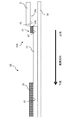
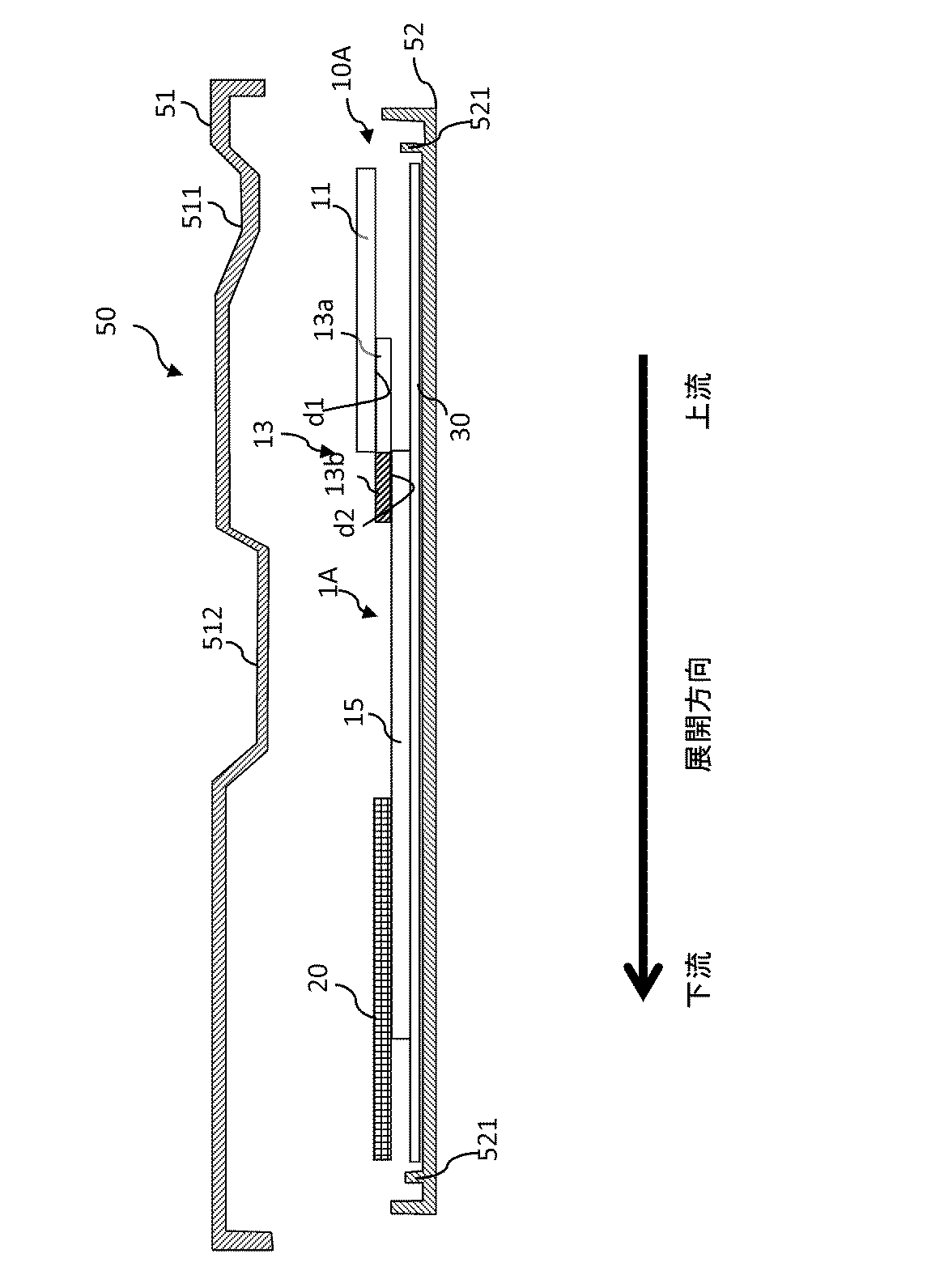
図1は、第一実施形態にかかる検査キット1Aの一例を示す平面図である。図2は、図1の検査キット1Aの側面図である。以下、第一実施形態にかかる検査キット1Aを、図を参照して説明する。
<検査キットの構成>
FIG. 1 is a plan view showing an example of a
<Configuration of inspection kit>
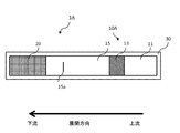
検査キット1Aは、液体試料を展開方向(以下、単に展開方向という場合がある)に展開させて、液体試料に含まれる被検出物質(抗原又は抗体、以下同じ)を検出するキットである。具体的には、検査キット1Aに滴下された液体試料の展開方向下流に設けられたテストラインが標識されるか否かにより、液体試料に被検出物質が含まれるか否かが判定される。液体試料の展開方向を矢印で図に示す。
The
検査キット1Aは、キット本体10Aと、吸収パッド20と、シート30とを有する。シート30は、例えば、防水性があり、上面が粘着性のある周知のシートでよい。シート30の上面には、キット本体10Aと吸収パッド20とが接続して配置される。キット本体10Aは、液体試料を展開することで、被検出物質(抗原又は抗体、以下同じ)の有無が判定される。吸収パッド20は、キット本体10Aを展開する液体試料を吸い上げる。
<各部材の説明>
The
<Description of each member>
キット本体10Aは、滴下領域としての試料滴下パッド11、標識化物質保持領域としての標識化物質保持パッド13、及び、展開領域としての固定化メンブレン15を有する。
The kit
試料滴下パッド11は、展開方向の最上流に配置される。試料滴下パッド11は、液体試料が滴下される滴下部分を有する(図示なし)。試料滴下パッド11は、所定の吸水力を有する。具体的には、試料滴下パッド11は、比較的吸水力の低い繊維部材で形成される。また、試料滴下パッド11は、比較的目が粗く液体の展開速度の速い繊維部材で形成される。
The
標識化物質保持パッド13は、その少なくとも一部が、試料滴下パッド11の展開方向下流に接続される。具体的には、標識化物質保持パッド13の展開方向上流側の端部は、試料滴下パッド11の展開方向下流側の端部の下に重ねて配置される。これにより、標識化物質保持パッド13の上面と試料滴下パッド11の下面によって接合面d1が形成される。標識化物質保持パッド13は、試料滴下パッド11よりも吸水力が高く、液体の展開速度が遅い。例えば、標識化物質保持パッド13は、試料滴下パッド11よりも、目の細かい繊維部材で形成される。また、標識化物質保持パッド13の吸水力は、一様である。液体試料は、接合面d1を介して、試料滴下パッド11を展開するよりも強い力で標識化物質保持パッド13に吸水される。
At least a part of the labeling
標識化物質保持パッド13には、標識化物質が保持される。標識化物質保持パッド13は、標識化物質を含有しない未含有部分13aと、標識化物質を含有する含有部分13bを有する。なお、接合面d1は、図示例のように、未含有部分13aの上面の全面に試料滴下パッド11の下面が接合することにより形成されてもよいし、未含有部分13aの上面の一部が試料滴下パッド11の下面に接合して形成されてもよい。
A labeling substance is held on the labeling
含有部分13bには、例えば、標識化物質が一様に保持されるが、これに限られない。ここで、標識化物質とは、液体試料中の被検出物質に特異的に結合する物質(抗体又は抗体、以下同じ)が、標識となる不溶性担体粒子、酵素標識リガンド、又は蛍光標識リガンドに固定化された物質である。標識となる不溶性担体粒子には、例えば、金コロイド、白金コロイド、着色粒子、蛍光粒子などがある。標識化物質保持パッド13に保持された標識化物質は、液体試料により流れ出し、液体試料とともに下流に展開する。液体試料に被検出物質が含まれる場合は、被検出物質と標識化物質とが特異的に結合し、標識化結合物質となって下流側に展開する。
For example, the labeling substance is uniformly held in the containing
固定化メンブレン15は、その少なくとも一部が、標識化物質保持パッド13の展開方向下流に接続される。具体的には、固定化メンブレン15の展開方向上流側の端部は、標識化物質保持パッド13の展開方向下流側の端部の下に重ねて配置される。これにより、固定化メンブレン15の上面と標識化物質保持パッド13の下面によって接合面d2が形成される。固定化メンブレン15は、標識化物質保持パッド13よりも吸水力が高く、液体の展開速度が遅い。例えば、固定化メンブレン15は、ニトロセルロースメンブレンなどの標識化物質保持パッド13よりも目の細かい繊維部材(膜体)で形成される。液体試料は、接合面d2を介して、標識化物質保持パッド13を展開するよりも強い力で固定化メンブレン15に吸水される。
At least a part of the immobilizing
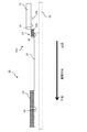
なお、図2では、接合面d2において、固定化メンブレン15の上面に含有部分13bのみが接するように配置されるがこれに限られない。例えば、図3に示すように、固定化メンブレン15の上面には、含有部分13bのみならず未含有部分13aが接するように配置されてもよい。また、例えば、図4に示すように、固定化メンブレン15の上面には、含有部分13bの一部が接するように配置されてもよい。
In addition, in FIG. 2, it arrange | positions so that only the containing
固定化メンブレン15は、被検出物質と特異的に結合する物質(抗体又は抗原、以下同じ)を固定化した領域である検出ゾーン15aを有する(図1参照)。検出ゾーン15aに標識化結合物質が特異的に結合し、標識化物質がライン状に捕獲されることで、テストラインが標識される。なお、図示はしないが、固定化メンブレン15は、さらに、コントロール用物質(抗体又は抗原、以下同じ)を固定化した領域であるコントロールゾーンを有するようにしてもよい。コントロールゾーンは、検出ゾーン15aの下流側に配置されるのが望ましい。この場合、標識化物質保持パッド13に、コントロール用物質に特異的に結合する物質(抗原又は抗体)に、標識のための不溶性担体粒子等を固定化させたコントロール用標識化物質をさらに保持させるなどにより、コントロールゾーンに(これらの標識化物質を含む)液体試料が展開したことが確認できる。
The
吸収パッド20は、キット本体10の液体試料を吸収するパッドである。吸収パッド20は、その少なくとも一部が、固定化メンブレン15の展開方向下流に接続される。具体的には、固定化メンブレン15の展開方向下流側の端部に、吸収パッド20の展開方向上流側の端部が載置される。これにより、吸収パッド20の上面と固定化メンブレン15の下面によって接合面d3が形成される。液体試料は、接合面d3を介して吸収パッドに吸水される。
The
なお、図2では(後述する他の側面図も同様である)、試料滴下パッド11、標識化物質保持パッド13及び吸収パッド20において、他の部材と接していない部分がシート30から離れているが、これらの部分はシート30に接着されていてもよい。
In FIG. 2 (the same applies to other side views described later), portions of the
また、検査キット1Aは、その上面を防水性のある材質の図示しないカバーで覆うようにしてもよい。この場合、カバーは、テストラインが視認できるように透明であり、かつ、滴下部分には、液体試料を通す開口が形成されてもよい。
Moreover, you may make it cover the test |
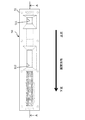
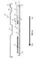
また、検査キット1Aは、ケースに収容して使用するようにしてもよい。図5は、ケース50の一例を示す平面図である。図6は、図5のA−A断面図である。
Moreover, you may make it use the test |
ケース50は、検査キット1を収容するケース本体52と、ケース本体52を覆う蓋体51とを有する。ケース本体52には、検査キット1の位置決めをする複数の突出部521が設けられる。蓋体51には、試料滴下領域パッド11に液体試料を滴下する為の開口部511、及び、固定化メンブレン15上のテストラインを視認するための開口部512が形成される。カバーで覆った検査キット1Aがケース50に収容されてもよいし、検査キット1Aがそのままケース50に収容されてもよい。なお、蓋体51及びケース52には、蓋体51を閉止する為のストッパーが設けられてもよい。
<各機能の説明>
The
<Description of each function>
検査キット1Aは、液体試料の迅速かつ確実な展開のために、第1及び/又は第2の機能を備える。第1の機能は、標識化物質を含む液体試料の、展開方向下流の部材から隣接する展開方向上流の部材への逆流を抑制する機能である。具体的には、第1の機能は、試料滴下パッド11の吸水力が標識化物質保持パッドの吸水力よりも低いという構成によってなされる。この構成により、標識化物質を含む液体試料の、標識化物質保持パッド13から試料滴下パッド11への逆流が抑制される。また、第1の機能は、標識化物質保持パッド13の吸水力が固定化メンブレン15の吸水力よりも低いという構成によってなされる。この構成により、標識化物質を含む液体試料の、固定化メンブレン15から標識化物質保持パッド13への逆流が抑制される。
The
第2の機能は、液体試料が標識化物質保持パッド13から固定化メンブレン15へ展開するときに、標識化物質が標識化物質保持パッド13に滞留するのを抑制する機能である。ここで、滞留とは、上流から下流に向かう液体試料の流れが乱れた場合に、その流れの乱れに巻き込まれて、標識化物質の流れが滞ることを意味する。液体試料の流れの乱れは、次の2つの事象が原因で起こりうる。
The second function is a function of suppressing the retention of the labeling substance on the labeling
1つは、試料滴下パッド11に比べて標識化物質保持パッド13の吸水力が高いという吸水力の段差により、標識化物質保持パッド13中に勢いよく液体試料が流れ込むことによる。もう1つは、接合面d1自体が障害になることによる。具体的には、接合面d1では、目の粗さの異なる繊維部材が接しており、また、2つの部材の間にごく僅かな隙間も存在するために、液体試料がスムースに流れないことによる。
One is that the liquid sample flows into the labeling
前述の通り、従来の検査キットaでは標識化物質を全体に一様に保持した標識化物質保持パッドfを用いていた(図15参照)。このため、接合面hからの流入による液体試料の流れの乱れに巻き込まれて、標識化試料が滞留するおそれがあった。さらには、試料滴下パッドeの下面が、標識化物質保持パッドfの上面に比較的広い範囲で接合されていた。このため、接合面hから液体が流入する範囲が広く、かつ、重力によって毛細管現象だけで流入するよりも勢いよく液体試料が標識化物質保持パッドfに流入し、液体試料の流れの乱れが増し、標識化物質の滞留を起こしていた。 As described above, in the conventional test kit a, the labeling substance holding pad f that holds the labeling substance uniformly is used (see FIG. 15). For this reason, there is a concern that the labeled sample may be retained due to the disturbance of the flow of the liquid sample due to the inflow from the joining surface h. Furthermore, the lower surface of the sample dropping pad e was bonded to the upper surface of the labeling substance holding pad f in a relatively wide range. For this reason, the range in which the liquid flows in from the joint surface h is wide, and the liquid sample flows into the labeling substance holding pad f more vigorously than inflowing only by capillary action due to gravity, and the disturbance of the flow of the liquid sample increases. , Retention of the labeled substance occurred.
第2の機能は、標識化物質保持パッド13の吸水力が一様であり、かつ、その最上流に未含有部分13aを配置させたという構成によってなされる。この構成により、従来のように、標識化物質を一様に保持した標識化物質保持パッドを用いた場合に比べて、最上流の未含有部分13aと含有部分13bの吸水力が一様であるため、標識化物質が存在する部分での液体試料の流れの乱れが少なく、液体試料の流れの乱れに巻き込まれて滞留する標識化物質を低減できる。また、第2の機能は、試料滴下パッド11が未含有部分13aにのみ接するという構成によってなされる。このとき、試料滴下パッド11は、未含有部分13aにのみに接していれば(つまり試料滴下パッド11が含有部分13bに接していなければ)、どのような位置に配置されてもよい。このように配置することで、液体試料は、試料滴下パッド11、未含有部分13a、含有部分13b、固定化メンブレン15の順に展開する。従って、液体試料の流入位置である接合面d2下に標識化物質が保持されていないため、接合面d2付近で液体試料の流れの乱れに巻き込まれる標識化物質の滞留を低減できる。
The second function is achieved by a configuration in which the water absorption force of the labeling
また、標識化物質の滞留が抑制されることで、含有部分13bから固定化メンブレン15に標識化物質をより速く流入させることができ、その後に標識化物質をほとんど含まない液体試料が流れることになるため、標識化物質が残留しにくい。
<検査キット内部の振る舞い>
In addition, since the retention of the labeling substance is suppressed, the labeling substance can be caused to flow faster from the containing
<Behavior of inspection kit>
以下、液体試料の滴下による検査キット1A内部の振る舞いを簡単に説明する。
Hereinafter, the behavior inside the
上述したように、キット本体10Aの各種部材は、吸水力の高い順に、固定化メンブレン15、標識化物質保持パッド13、試料滴下パッド11である。これら部材を上述のように配置したことにより、検査キット1Aの試料滴下パッド11に滴下される液体試料は、以下のように流れる。
(*)液体試料は、試料滴下パッド11を展開し、接合面d1を介して、試料滴下パッド11を展開するよりも高い吸水力で標識化物質保持パッド13に吸収される。この際、第2の機能により、液体試料は、未含有部分13aに流入し、未含有部分13aで流れを整え、未含有部分13aから含有部分13bに向かって静かに流れながら、含有部分13bに保持された標識化物質を流し出す。
(*)流し出された標識化物質は、接合面d2を介して、標識化物質保持パッド13を展開するよりも強い力(吸水力)で液体試料とともに固定化メンブレン15に吸収される。このとき、含有部分13bからおおよそ標識化物質が流し出された後も、未含有部分13aに残る液体試料が標識化物質を流し出す。
(*)液体試料に被検出物質が含まれる場合には、展開中、被検出物質に標識化物質が結合し標識化結合物質が生成される。その後、検出ゾーン15aの固定化試料に標識化結合物質が結合し、テストラインとして標識される。
(*)固定化メンブレン15を展開した液体試料は、接合面d3に到達すると、吸収パッド20に吸収される。
As described above, the various members of the kit main body 10 </ b> A are the immobilized
(*) The liquid sample is developed on the
(*) The labeling substance that has flowed out is absorbed by the immobilizing
(*) When the substance to be detected is contained in the liquid sample, the labeling substance is bound to the substance to be detected during the development to generate a labeled binding substance. Thereafter, the labeled binding substance binds to the immobilized sample in the
(*) When the liquid sample in which the immobilized
以上より、検査キット1Aは、第2の機能によって、液体試料が接合面d1から最上流の未含有部分13aのみに流入し、その後、吸水力が一様な含有部分13bに流れることで、液体試料の流れの乱れに標識化物質が巻き込まれるのを防ぎ、標識化物質の滞留を抑制できる。また、標識化物質が液体試料の流れの乱れに巻き込まれた場合であっても、第1の機能により、上流側の部材へ逆流するのを防止できる。これら機能を設けたことにより、標識化物質が、より速く固定化メンブレン15に流入し、さらに残りの液体試料が標識化物質の流れを促進させることができ、迅速かつ高感度の検出を行うことができる。
<<第二実施形態>>
As described above, the
<< Second Embodiment >>
図7は、第二実施形態にかかる検査キットの一例を示す平面図である。以下、図を参照して、第二実施形態にかかる検査キット1Bの一例を説明する。
FIG. 7 is a plan view showing an example of a test kit according to the second embodiment. Hereinafter, an example of the
標識化物質保持領域としての標識化物質保持パッド13は、その少なくとも一部が、滴下領域としての試料滴下パッド11の展開方向下流に接続される。具体的には、隣り合う標識化物質保持パッド13の展開方向上流側の端面と、試料滴下パッド11の展開方向下流側の端面とが接するように配置される。これにより、接合面d4が形成される。
At least a part of the labeling
本実施形態にかかる第2の機能をなす構成として、標識化物質保持パッド13の最上流に未含有部分13aを設けたことに加え、未含有部分13aの上流側の端面に、試料滴下パッド11の下流側の端面が接続する。従って、検査キット1Bは、液体試料の流入位置に標識化物質が保持されていないため、液体試料の流れの乱れに巻き込まれて標識化物質が滞留するのを抑制することができる。加えて、検査キット1Bは、未含有部分13aの端面と試料滴下パッド11の端面とを隣りあわせて接続することで、未含有部分13aの上に試料滴下パッド11を重ねて配置する場合に比べて接合面d4の面積が小さくでき、また、重力の影響を受けずに液体試料の流入量を少なくできるため、液体試料の流れの乱れを抑えて、標識化物質の滞留をより抑制できる。
As a configuration having the second function according to the present embodiment, in addition to providing the
上記では、それぞれ別個の部材で形成された、標識化物質保持パッド13の上流側の端面と、試料滴下パッド11の下流側の端面とを接続させていた。しかし、これらは、標識化物質保持領域と滴下領域とが、一片の部材によって一体的に形成されてもよい。以下、詳細に説明する。
In the above, the upstream end surface of the labeling
図8は、本実施形態にかかる1つの変形例を示す側面図である。図9は、図8の第1のパッド17を示す平面図である。
FIG. 8 is a side view showing one modification according to the present embodiment. FIG. 9 is a plan view showing the
キット本体10Baは、展開領域としての固定化メンブレン15と、第1のパッド17とを有する。第1のパッド17は、所定の吸水力を有する滴下領域171と、滴下領域171よりも吸水力の高い標識化物質保持領域172とが,一片の部材によって一体的に形成されたパッドである。標識化物質保持領域172は、標識化物質を含有しない未含有部分172aと、標識化物質が含有される含有部分172bとを有する。含有部分172bは、例えば、標識化物質を一様に保持するが、これに限られない。第1のパッド17は、標識化物質保持領域172の吸水力が滴下領域171よりも高くなるように、標識化物質保持領域172のみを圧縮形成してもよい。具体的には、例えば、第1のパッド17は、標識化物質保持領域172の吸水力が滴下領域171よりも高くなるように加熱圧縮等により形成された一体形成のパッドでも良いし、標識化物質保持領域172の吸水力が滴下領域171よりも高くなるように異なる材質の繊維を熱融着等により貼り合わせて一体にしたパッドでも良い。
The kit body 10Ba has an immobilizing
検査キット1Baは、第1のパッド17において、吸水力の異なる滴下領域及び標識化物質保持領域を一片の部材によって一体形成することで、組み立てを簡易にすることができる。
The test kit 1Ba can be easily assembled by integrally forming the dropping area and the labeling substance holding area having different water absorption capabilities with one piece of member in the
図10は、本実施形態にかかる他の1つの変形例を示す側面図である。 FIG. 10 is a side view showing another modification according to the present embodiment.
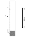
本例の検査キット1Dでは、目の粗さ(つまり、吸水力)が均一な繊維材としての第1のパッド27の長手方向の下流側の端部を所望の圧力で押圧することにより、標識化物質保持領域が形成される。具体的には、例えば、第1のパッド27は、ケース60に収容されることにより、標識化物質保持領域となる部分が所望の圧力で押圧される。以下、これを説明する。
In the
第1のパッド27は、標識化物質を一様に含有する含有領域27Bを有する。含有領域27Bは、第1のパッド27の長手方向の一方の端部を、標識化物質を含有する溶液に含浸した後、乾燥して形成する。なお、第1のパッド27の含有領域27B以外の領域27A(以下、未含有領域27Aという場合がある)には、標識化物質は保持されない。
The first pad 27 has a containing
ケース60は、検査キット1Dを収容するケース本体62と、ケース本体62を覆う蓋体61とを有する。ケース本体62には、例えば、検査キット1の位置決めをする複数の突出部621が立設される。蓋体61には、試料滴下領域171に液体資料を滴下する為の開口部611、及び、固定化メンブレン15上のテストラインを視認するための開口部612が形成される。蓋体61には、第1のパッド27に標識化物質保持領域を形成するための押圧部613Aが形成される。押圧部613Aは、ケース60に検査キット1Dを収容した状態で、第1のパッド27の下流側の端部(具体的には、含有領域27B及び未含有領域27Aの下流側の一部分)に対向する位置に設けられる。従って、第1のパッド27の検査キット1Dがケース本体62に収容された場合には、押圧部613Aによって、第1のパッド27の下流側の端部の繊維がつぶれて、第1のパッド27に吸水力の段差ができ、試料滴下領域と、試料滴下領域よりも吸水力の高い標識化物質保持領域とが形成される。
The
上記実施形態においては、ケース60に押圧部613Aを設けたことにより、ケース60に組み込む前に第1のパッド27を加工する必要がなく、簡易な製造が可能となる。なお、蓋体61には、固定化メンブレン15の下流側(例えば、テストライン位置よりも下流側であって、吸収パッド20と固定化メンブレン15の接合面d2付近)を押圧するための突起614を設けてもよい。これにより、固定化メンブレン15の下流側の繊維がつぶれて、液体試料の流れをスムースにすることができる。
In the above embodiment, by providing the
また、上記では、ケース60の蓋体61に押圧部613Aを形成していたがこれに限られない。例えば、押圧部は、ケース本体62の底部に突出形成してもよい。さらに、ケース60を用いずに、第1のパッド27の下流側の端部を所定の押圧力で上下方向から拘束する拘束部材などを用いてもよい。
<<第三実施形態>>
Moreover, although the
<< Third embodiment >>
図11は、第三実施形態にかかる検査キットの一例を示す平面図である。以下、図を参照して、第三実施形態にかかる検査キット1Cの一例を説明する。
FIG. 11 is a plan view showing an example of a test kit according to the third embodiment. Hereinafter, an example of a
本実施形態においては、標識化物質保持パッド13は、未含有部分を有さず、含有部分13bのみで形成される。含有部分13bは、例えば、標識化物質を一様に保持するが、これに限られず一様でなくてもよい。
In the present embodiment, the labeling
標識化物質保持パッド13は、その少なくとも一部が、滴下領域としての試料滴下パッド11の展開方向下流に接続される。具体的には、隣り合う標識化物質保持パッド13の展開方向上流側の端面と、試料滴下パッド11の展開方向下流側の端面とが接続される。これにより、接合面d6が形成される。
At least a part of the labeling
本実施形態にかかる第2の機能は、標識化物質保持パッド13(つまり含有部分13b)の上流側の端面に、試料滴下パッド11の下流側の端面が接続される構成によってなる。従って、検査キット1Cは、標識化物質保持パッド13の端面と試料滴下パッド11の端面とを隣り合わせて配置することで、標識化物質保持パッド13に試料滴下パッド11を重ねて配置する場合に比べてこれらの接合面の面積が小さくできるため、液体試料の流入量を少なくできかつ重力の影響も受けずに、液体試料の流れの乱れを抑えて、液体試料の流れの乱れに巻き込まれる標識化物質の滞留を抑制できる。
The second function according to the present embodiment has a configuration in which the downstream end surface of the
上記では、標識化物質保持パッド13の上流側の端面と試料滴下パッド11の下流側の端面とを接続させていた。しかし、これらは、標識化物質保持領域と滴下領域とが、一片の部材によって一体的に形成されてもよい。以下、詳細に説明する。
In the above, the upstream end face of the labeling
図12は、本実施形態にかかる1つの変形例を示す側面図である。図13は、図12の第2のパッド18を示す平面図である。
FIG. 12 is a side view showing one modification according to the present embodiment. FIG. 13 is a plan view showing the
キット本体10Caは、展開領域としての固定化メンブレン15と、第2のパッド18とを有する。第2のパッド18は、所定の吸水力を有する滴下領域181と、滴下領域181よりも吸水力の高い標識化物質保持領域182とが一体的に形成されたパッドである。標識化物質保持領域182は、未含有部分を有さず、含有部分182bのみで形成される。含有部分182bは、例えば、標識化物質を一様に保持するが、これに限られない。第2のパッド18は、標識化物質保持領域182の吸水力が滴下領域181よりも高くなるように、標識化物質保持領域182のみを圧縮形成してもよい。具体的には、例えば、第2のパッド18は、標識化物質保持領域182の吸水力が滴下領域181よりも高くなるように加熱圧縮等により形成された一体形成のパッドでも良いし、標識化物質保持領域182の吸水力が滴下領域181よりも高くなるように異なる材質の繊維を熱融着等により貼り合わせて一体にしたパッドでも良い。
The kit main body 10Ca includes an immobilizing
検査キット1Caは、第2のパッド18において、吸水力の異なる滴下領域と標識化物質保持領域とを含む一片の部材によって一体形成することで、組み立てを簡易にすることができる。
The test kit 1Ca can be easily assembled in the
図14は、本実施形態にかかる他の1つの変形例を示す側面図である。 FIG. 14 is a side view showing another modification according to the present embodiment.
本例では、前述した、目の粗さ(つまり、吸水力)が均一な繊維材としての第1のパッド27とケース60とを用いる。第1のパッド27は、例えば、ケース60に収容されることにより、標識化物質保持領域となる部分が所望の圧力で押圧される。
In this example, the first pad 27 and the
蓋体には、押圧部613Bが形成される。押圧部613Bの位置は、ケース60に検査キット1Dを収容した状態で、第1のパッド27の下流側の端部(具体的には、含有領域27Bのみ)に対向する位置に設定される。従って、第1のパッド27の検査キット1Dがケース本体62に収容された場合には、押圧部613Bによって、第1のパッド27の下流側の端部の繊維がつぶれて、第1のパッド27に吸水力の段差ができ、試料滴下領域と、試料滴下領域よりも吸水力の高い標識化物質保持領域とが形成される。
A
上記実施形態においては、ケース60に押圧部613Bを設けたことにより、ケース60に組み込む前に第1のパッド27を加工する必要がなく、簡易な製造が可能となる。
In the above embodiment, by providing the
また、上記では、ケース60の蓋体61に押圧部613Bを形成していたがこれに限られない。例えば、押圧部は、ケース本体62の底部に突出形成してもよい。さらに、ケース60を用いずに、第1のパッド27の下流側の端部を所定の押圧力で上下方向から拘束する拘束部材などを用いてもよい。
Moreover, although the
以上、本発明の幾つかの実施形態を説明したが、これらは本発明の説明のための例示であって、本発明の範囲をこれらの実施形態にのみ限定する趣旨ではない。本発明は、他の種々の形態でも実施することが可能である。 As mentioned above, although several embodiment of this invention was described, these are the illustrations for description of this invention, Comprising: It is not the meaning which limits the scope of the present invention only to these embodiment. The present invention can be implemented in various other forms.
次に、実施例1として、本発明にかかる検査キットと従来の検査キットとの比較実験について説明する。 Next, as Example 1, a comparative experiment between a test kit according to the present invention and a conventional test kit will be described.
以下、2つの実験を説明する。なお、実験には、A型インフルエンザウイルス抗原(被検出物質)検出のための検査キットを用いた。また、標識となる不溶性担体粒子に蛍光ポリスチレン粒子を用いた。
<<第1の実験>>
Two experiments will be described below. In the experiment, a test kit for detecting influenza A virus antigen (substance to be detected) was used. In addition, fluorescent polystyrene particles were used as insoluble carrier particles serving as labels.
<< First Experiment >>
第1の実験は、第一実施形態にかかる検査キットと、従来の検査キットとの標識化物質の展開速度を対比するための実験である。具体的には、液体試料滴下後、所定時間毎のテストライン位置付近(以下、バックグラウンドという場合がある)に残留する標識化物質の有無を判定する。以下の実験の説明においては、従来の検査キットを検査キットA、第一実施形態にかかる検査キットを検査キットBとして説明する。また、バックグラウンドに残留する標識化物質の有無を判定する時間をバックグランド判定時間という。以下、順に説明する。 The first experiment is an experiment for comparing the development rate of the labeled substance between the test kit according to the first embodiment and the conventional test kit. Specifically, after the liquid sample is dropped, the presence / absence of a labeling substance remaining in the vicinity of the test line position (hereinafter sometimes referred to as background) every predetermined time is determined. In the following description of the experiment, the conventional test kit will be described as test kit A, and the test kit according to the first embodiment will be described as test kit B. The time for determining the presence or absence of the labeled substance remaining in the background is referred to as background determination time. Hereinafter, it demonstrates in order.
<抗体の作製> <Production of antibody>
抗体の作製は、次の手順で行った。
(*)A型インフルエンザウイルス抗原をBALB/cマウスに免疫して、一定期間飼育したマウスから脾臓を摘出し、マウスミエローマ細胞と融合させて、融合細胞(ハイブリドーマ)を生成した。
(*)融合細胞(ハイブリドーマ)を所定温度下で維持し、A型インフルエンザウイルスNP抗原を固相化したプレートを用いたELISAにより、上清の抗体活性を確認しながら細胞の純化(単クローン化)を行った。
(*)取得した単クローン化細胞2株を、それぞれBALB/cマウスに腹腔投与し、所定期間後、それぞれのマウスから抗体含有腹水を採取した。
(*)得られた2種類の腹水からそれぞれIgGを精製し、2種類の精製抗A型インフルエンザウイルスNP抗体を得た。
The antibody was produced by the following procedure.
(*) A BALB / c mouse was immunized with influenza A virus antigen, and the spleen was extracted from a mouse bred for a certain period and fused with mouse myeloma cells to generate a fused cell (hybridoma).
(*) Maintaining the fused cells (hybridoma) at a predetermined temperature, and purifying the cells by confirming the antibody activity of the supernatant by ELISA using a plate on which influenza A virus NP antigen is immobilized (monocloning) )
(*) Each of the obtained 2 cloned monoclonal cells was intraperitoneally administered to BALB / c mice, and after a predetermined period, antibody-containing ascites was collected from each mouse.
(*) IgG was purified from each of the obtained two types of ascites to obtain two types of purified anti-influenza A virus NP antibodies.
<固定化メンブレンの作製> <Preparation of immobilized membrane>
固定化メンブレンの作製は、次の手順で行った。
(*)第1の抗A型インフルエンザウイルスNP抗体を精製水で所定濃度に希釈した。
(*)希釈溶液をニトロセルロースメンブレンの所定の位置にライン状に塗布・乾燥させて、抗A型インフルエンザウイルスNP抗体を固定した検出ゾーンを生成し、固定化メンブレンを得た。
The immobilization membrane was produced by the following procedure.
(*) The first anti-influenza A virus NP antibody was diluted to a predetermined concentration with purified water.
(*) The diluted solution was applied to a predetermined position of the nitrocellulose membrane in a line and dried to generate a detection zone on which the anti-influenza A virus NP antibody was immobilized, thereby obtaining an immobilized membrane.
<標識化物質の調製> <Preparation of labeling substance>
標識化物質の調製は、次の手順で行った。
(*)第2の抗A型インフルエンザウイルスNP抗体を精製水で所定濃度に希釈し、希釈溶液に蛍光ポリスチレン粒子を加え撹拌した。
(*)架橋剤を加えさらに撹拌し、遠心操作により、上清を除いた後調整し、標識化物質(抗A型インフルエンザウイルNP抗体結合蛍光ポリスチレン粒子)を得た。
The labeled substance was prepared by the following procedure.
(*) The second anti-influenza A virus NP antibody was diluted with purified water to a predetermined concentration, and fluorescent polystyrene particles were added to the diluted solution and stirred.
(*) A cross-linking agent was added, the mixture was further stirred, and the supernatant was removed by centrifugation to prepare a labeling substance (anti-influenza A influenza virus NP antibody-binding fluorescent polystyrene particles).
<標識化物質保持パッドの作製> <Preparation of labeled substance holding pad>
標識化物質保持パッドの作製は、次の通りである。
標識化物質を2.0,1.5,1.2,0.8,0.4μgになるように、それぞれパッド(グラスファイバー不織布)に塗布し、乾燥させた。具体的には、上記5種類の粒子量のパッド(2.0,1.5,1.2,0.8,0.4μg)について、それぞれ、標識化物質が一様に塗布された従来型の標識化物質保持パッド(A)と、未含有部分を有する第一実施形態に係る標識化物質保持パッド(B)とを作成した。
The production of the labeling substance holding pad is as follows.
The labeling substances were applied to pads (glass fiber nonwoven fabric) so as to be 2.0, 1.5, 1.2, 0.8, and 0.4 μg, respectively, and dried. Specifically, the conventional labeling substance holding pad (A) in which the labeling substance is uniformly applied to the five kinds of particle amount pads (2.0, 1.5, 1.2, 0.8, 0.4 μg), respectively. And the labeled substance holding pad (B) which concerns on 1st embodiment which has a non-containing part was created.
<検査キットの組み立て> <Assembly of inspection kit>
検査キットの組み立ては、次の通りである。
粘着性有するシートの上面に、キット本体(固定化メンブレン、標識化物質保持パッド及び試料滴下パッド)と吸収パッドとを配置する。従来の検査キットAの配置は、図11の通りである(図中では、検査キットa)。第一実施形態の検査キットBの配置は、図1及び2の通りである(図中では、検査キット1A)。
The assembly of the inspection kit is as follows.
A kit body (an immobilizing membrane, a labeling substance holding pad and a sample dropping pad) and an absorption pad are disposed on the upper surface of the adhesive sheet. The arrangement of the conventional test kit A is as shown in FIG. 11 (in the figure, test kit a). The arrangement of the test kit B of the first embodiment is as shown in FIGS. 1 and 2 (in the figure, the
<液体試料の調製> <Preparation of liquid sample>
所定の条件により、液体試料を調製した。 A liquid sample was prepared according to predetermined conditions.
<バックグラウンド測定> <Background measurement>
バックグラウンド測定は、次の手順で行った。
(*)液体試料50μLを、滴下パッドに滴下し、各検査キットに標識化物質が展開する様子を観察した。固定化メンブレンに標識化物質を目視で観察した。
(*)観察は1分毎に行った。
(*)また、正確を期すためトランスイルミネーター上での観察とした。明らかに標識化物質が残っている場合をバックグラウンド(+)、標識化物質がほとんど見えない場合をバックグラウンド(−)と判定した。
<結果>
The background measurement was performed according to the following procedure.
(*) A liquid sample (50 μL) was dropped onto a dropping pad, and the appearance of the labeling substance on each test kit was observed. The labeled substance was visually observed on the immobilized membrane.
(*) Observation was performed every minute.
(*) Also, for the sake of accuracy, observation on a transilluminator was performed. The case where the labeling substance remained clearly was judged as background (+), and the case where the labeling substance was hardly visible was judged as background (-).
<Result>
結果を表1に示す。
標識化物質保持パッドに保持される粒子量が全ての場合において、検査キットBは検査キットAに比べて、短い時間でバックグランド(−)と判定された。つまり、標識化物質保持パッドに保持される標識化物質の量に関わらず、検査キットAよりも検査キットBが迅速に標識化物質を展開できることが本実験においてわかった。別の見方をする場合、滴加後比較的早い判定時間である8〜10分では、検査キットAよりも検査キットBの方がより多くの標識化物質を載せることができることがわかった。 In all cases where the amount of particles held on the labeling substance holding pad was the test kit B, the test kit B was determined to be background (-) in a shorter time than the test kit A. That is, it was found in this experiment that the test kit B can develop the labeling substance more quickly than the test kit A regardless of the amount of the labeling substance held on the labeling substance holding pad. From another point of view, it was found that the test kit B can load more labeled substance than the test kit A at 8 to 10 minutes, which is a relatively early determination time after the addition.
<<第2の実験>> << Second Experiment >>
第1の実験から、検査キットBは、検査キットAよりも迅速に標識化物質を含む液体試料を展開できることはわかった。しかし、迅速であっても感度がよくなければ、正確な判定は行えない。第2の実験は、第一実施形態にかかる検査キットと、従来の検査キットとの標識化物質の感度を対比するための実験である。以下、順に説明する。
<液体試料(被検出物質を含む)の調製>
From the first experiment, it was found that the test kit B can develop the liquid sample containing the labeled substance more rapidly than the test kit A. However, accurate determination cannot be made if the sensitivity is not good even if it is rapid. The second experiment is an experiment for comparing the sensitivity of the labeled substance between the test kit according to the first embodiment and the conventional test kit. Hereinafter, it demonstrates in order.
<Preparation of liquid sample (including substance to be detected)>
液体試料(被検出物質を含む)の調製は、以下の通りである。
原液には、被検出物質(A型インフルエンザウイルスNP抗原)溶液を用い、2倍希釈系列(21、22、23、24、25、26、27)の7種の液体試料(被検出物質を含む)を調製
した。
<測定>
The preparation of the liquid sample (including the substance to be detected) is as follows.
As the stock solution, a substance to be detected (type A influenza virus NP antigen) solution is used, and seven types of liquids of a 2-fold dilution series (2 1 , 2 2 , 2 3 , 2 4 , 2 5 , 2 6 , 2 7 ) are used. A sample (including a substance to be detected) was prepared.
<Measurement>
測定は、次の手順で行った。
(*)検査キットA及びBに、上記7種の液体試料(被検出物質を含む)を50μL滴下し、測定時間経過後に、テストラインの標識が目視により識別できるか否かを判定した。
(*)測定時間は8分とした。
(*)実験2では、実験1での測定時間8分の時に、バックグラウンドが(−)であった以下の検査キットを対象とした。つまり、迅速な検査を行うための測定時間を8分と仮定し、実験1でバックグラウンド(−)となる測定時間が8分以上のものについては、対象外とした。
・検査キットA(粒子量:0.4μg)
・検査キットB(粒子量:0.8μg及び1.5μg)
(*)また、正確を期すためトランスイルミネーター上での観察とした。テストラインの標識が識別可能な場合をテストライン(+)、テストラインの標識が識別不可能な場合をテストライン(−)と判定した。
The measurement was performed according to the following procedure.
(*) 50 μL of the above seven types of liquid samples (including the substance to be detected) were dropped on the test kits A and B, and it was determined whether or not the test line label could be visually identified after the measurement time had elapsed.
(*) Measurement time was 8 minutes.
(*) In
・ Test kit A (Particle amount: 0.4μg)
・ Test kit B (Particle amount: 0.8μg and 1.5μg)
(*) Also, for the sake of accuracy, observation on a transilluminator was performed. The test line (+) was determined when the test line label was identifiable, and the test line (-) was determined when the test line label was not identifiable.
<結果>
結果を表2に示す。
The results are shown in Table 2.
上記は、液体試料(被検出物質を含む)を各検査キットに滴下して8分後のテストライン判定である。検査キットBは検査キットAに比べて、テストライン(+)となる液体試料(被検出物質を含む)の希釈率が高かった。特に、1.5μgの粒子量の標識化物質保持パッドを有する検査キットBでは、26という高い希釈率の液体試料(被検出物質を含む)を用いてもテストラインの標識が識別できた。つまり、滴下後比較的早い8分という時間において、検査キットAに比べて検査キットBの方が、感度が高いことが本実験においてわかった。 The above is a test line determination 8 minutes after a liquid sample (including a substance to be detected) is dropped on each test kit. The test kit B had a higher dilution rate of the liquid sample (including the substance to be detected) serving as the test line (+) than the test kit A. In particular, in the test kit B having a labeled substance holding pad having a particle amount of 1.5 μg, the test line label could be identified even when a liquid sample (including the substance to be detected) having a high dilution ratio of 26 was used. That is, it was found in this experiment that the test kit B has higher sensitivity than the test kit A at a time of 8 minutes, which is relatively early after dropping.
上記第1及び第2の実験より、検査キットBは、検査キットAに比べて迅速かつ高感度な被検出物質の検出が可能であることがわかった。 From the first and second experiments, it was found that the test kit B can detect the detection target substance more quickly and with higher sensitivity than the test kit A.
1A.検査キット 10A.キット本体 11.試料滴下パッド 13.標識化物質保持パッド 13a.未含有部分 13b.含有部分 15.固定化メンブレン 20.吸収パッド 30.シート
1A.
Claims (5)
前記液体試料を滴下する部分を含む滴下領域と、
前記滴下領域の展開方向下流に少なくとも一部が接続され、前記被検出物質に特異に結合する物質に標識を固定した標識化物質が保持される標識化物質保持領域と、
前記被検出物質を介して前記標識化物質を捕集する検出ゾーンを有し、前記標識化物質保持領域の展開方向下流に、その少なくとも一部が接続され、前記液体試料により前記標識化物質保持領域から流れ出した前記標識化物質を前記検出ゾーンに展開させる展開領域と、
前記液体試料が下流に展開するときに、前記標識化物質が前記標識化物質保持領域に滞留するのを抑制する滞留抑制手段と、
前記標識化物質を含む液体試料が、展開方向下流の領域から、隣接する展開方向上流の領域へ逆流するのを抑制する逆流抑制手段と、
を有し、
前記滞留抑制手段においては、
前記標識化物質保持領域が、前記標識化物質が一様に保持された含有部分と、前記標識化部分を含まない未含有部分と、で構成され、
前記標識化物質保持領域の吸水力が、一様に設定され、
前記標識化物質保持領域の最上流部に前記未含有部分が配置され、
前記標識化物質保持領域の前記未含有部分の下流に前記含有部分が配置され、
前記滴下領域の下流側と、前記未含有部分と、を接合させた第1の接合面が形成され、
前記含有部分と、前記展開領域の上流側と、を接合させた第2の接合面が形成され、
前記逆流抑制手段においては、
前記標識化物質保持領域の吸水力が、前記滴下領域の吸水力よりも高く設定され、
前記展開領域の吸水力が、前記標識化物質保持領域の吸水力よりも高く設定される、
検査キット。
A test kit for developing a liquid sample in a development direction to detect a substance to be detected contained in the liquid sample,
A dropping region including a portion for dropping the liquid sample;
A labeled substance holding region in which at least a part is connected downstream in the development direction of the dropping area, and a labeled substance holding a label on a substance that specifically binds to the substance to be detected is held;
It has a detection zone for collecting the labeled substance through the substance to be detected, and at least a part thereof is connected downstream of the labeling substance holding region in the developing direction, and the labeled substance is held by the liquid sample. A deployment region for deploying the labeled substance flowing out of the region to the detection zone;
When the liquid sample is developed downstream, a retention suppressing unit that suppresses retention of the labeling substance in the labeling substance holding region;
Backflow suppression means for suppressing the liquid sample containing the labeling substance from flowing backward from the downstream region in the development direction to the adjacent upstream region in the development direction;
I have a,
In the retention suppression means,
The labeling substance holding region is composed of a containing part in which the labeling substance is uniformly held, and a non-containing part not containing the labeling part,
The water absorption capacity of the labeling substance holding region is set uniformly,
The non-containing part is arranged at the most upstream part of the labeling substance holding region,
The containing part is arranged downstream of the non-containing part of the labeling substance holding region,
A first joining surface is formed by joining the downstream side of the dripping region and the non-containing portion,
A second joining surface is formed by joining the containing portion and the upstream side of the development region;
In the backflow suppression means,
The water absorption capacity of the labeling substance holding area is set higher than the water absorption capacity of the dropping area,
The water absorption capacity of the development area is set higher than the water absorption capacity of the labeling substance holding area.
Inspection kit.
請求項1に記載の検査キット。The test kit according to claim 1.
請求項2に記載の検査キット。The test kit according to claim 2.
請求項3記載の検査キット。
The test kit according to claim 3, wherein the dripping region and the labeling substance holding region are integrally formed by a single piece of member.
請求項4記載の検査キット。
5. The inspection according to claim 4 , wherein the one piece member is a fiber member having a uniform water absorption force, and the labeling substance holding region is formed by pressing a portion that becomes the labeling substance holding region. kit.
Priority Applications (6)
| Application Number | Priority Date | Filing Date | Title |
|---|---|---|---|
| JP2013050974A JP6180761B2 (en) | 2013-03-13 | 2013-03-13 | Inspection kit |
| KR1020157025810A KR102182713B1 (en) | 2013-03-13 | 2014-03-12 | Examination kit |
| ES14764277T ES2752466T3 (en) | 2013-03-13 | 2014-03-12 | Exam kit |
| US14/775,176 US9897601B2 (en) | 2013-03-13 | 2014-03-12 | Test kit |
| EP14764277.1A EP2975407B1 (en) | 2013-03-13 | 2014-03-12 | Examination kit |
| PCT/JP2014/056518 WO2014142179A1 (en) | 2013-03-13 | 2014-03-12 | Examination kit |
Applications Claiming Priority (1)
| Application Number | Priority Date | Filing Date | Title |
|---|---|---|---|
| JP2013050974A JP6180761B2 (en) | 2013-03-13 | 2013-03-13 | Inspection kit |
Publications (2)
| Publication Number | Publication Date |
|---|---|
| JP2014178152A JP2014178152A (en) | 2014-09-25 |
| JP6180761B2 true JP6180761B2 (en) | 2017-08-16 |
Family
ID=51536830
Family Applications (1)
| Application Number | Title | Priority Date | Filing Date |
|---|---|---|---|
| JP2013050974A Active JP6180761B2 (en) | 2013-03-13 | 2013-03-13 | Inspection kit |
Country Status (6)
| Country | Link |
|---|---|
| US (1) | US9897601B2 (en) |
| EP (1) | EP2975407B1 (en) |
| JP (1) | JP6180761B2 (en) |
| KR (1) | KR102182713B1 (en) |
| ES (1) | ES2752466T3 (en) |
| WO (1) | WO2014142179A1 (en) |
Families Citing this family (4)
| Publication number | Priority date | Publication date | Assignee | Title |
|---|---|---|---|---|
| JP6180761B2 (en) | 2013-03-13 | 2017-08-16 | デンカ生研株式会社 | Inspection kit |
| JP6105335B2 (en) | 2013-03-13 | 2017-03-29 | デンカ生研株式会社 | Inspection kit |
| JP6777468B2 (en) * | 2016-09-01 | 2020-10-28 | デンカ株式会社 | Inspection kit |
| CN117269479A (en) * | 2017-12-15 | 2023-12-22 | 电化株式会社 | Inspection kit and method for detecting substance to be detected using inspection kit |
Family Cites Families (26)
| Publication number | Priority date | Publication date | Assignee | Title |
|---|---|---|---|---|
| JP3134231B2 (en) | 1991-04-16 | 2001-02-13 | 東洋紡績株式会社 | Solid-phase biological specific reaction measurement method and instrument therefor |
| US5356782A (en) * | 1992-09-03 | 1994-10-18 | Boehringer Mannheim Corporation | Analytical test apparatus with on board negative and positive control |
| ES2264580T3 (en) | 1998-03-30 | 2007-01-01 | Orasure Technologies, Inc. | COLLECTION DEVICE FOR ANALYSIS IN A SINGLE STAGE OF ORAL FLUIDS. |
| JP2001021562A (en) | 1999-07-09 | 2001-01-26 | Nitto Denko Corp | Test piece for enzyme immunity chromatograph |
| GB9925461D0 (en) * | 1999-10-27 | 1999-12-29 | Genosis Ltd | Assay device |
| US6699722B2 (en) * | 2000-04-14 | 2004-03-02 | A-Fem Medical Corporation | Positive detection lateral-flow apparatus and method for small and large analytes |
| JP2002202307A (en) | 2000-12-27 | 2002-07-19 | Iatron Lab Inc | Immunochromatography |
| US6492127B2 (en) | 2001-01-23 | 2002-12-10 | Varian, Inc. | Lateral flow testing device with on-board chemical reactant |
| JP2003083970A (en) * | 2001-07-03 | 2003-03-19 | Mitsubishi Chemicals Corp | Method for measuring substance to be inspected using test piece and measuring instrument therefor |
| US20040161857A1 (en) | 2002-04-05 | 2004-08-19 | Keiko Yugawa | Test strip for chromatography and process for producing the same |
| US6875185B2 (en) | 2002-07-29 | 2005-04-05 | Branan Medical Corporation | Integrated confirmation sample in a body fluid test device and method of using |
| WO2006093797A2 (en) | 2005-02-28 | 2006-09-08 | Mj Biologics, Inc. | Method and kit for detecting porcine reproductive and respiratory syndrome virus |
| EP1909103A4 (en) | 2005-07-14 | 2011-05-04 | Panasonic Corp | Analyzer and analyzing method |
| JP2007086026A (en) * | 2005-09-26 | 2007-04-05 | Sysmex Corp | Kit for immuno-chromatography, and testing vessel |
| KR100735080B1 (en) | 2006-08-03 | 2007-07-03 | (주)래피젠 | Immunochromatographic strip for use in immunoassay and kit comprising the same |
| JP2008164520A (en) | 2006-12-28 | 2008-07-17 | Aisin Seiki Co Ltd | Detection device utilizing antigen-antibody reaction |
| US20110124130A1 (en) | 2008-04-03 | 2011-05-26 | Peter Wagner | Device and method for analysis of samples with depletion of analyte content |
| JP2010156571A (en) | 2008-12-26 | 2010-07-15 | Fujifilm Corp | Chromatography device |
| KR20120107840A (en) | 2009-04-15 | 2012-10-04 | 렐리아 다이어그노스틱 시스템스, 인크. | Diagnostic devices and related method |
| US8105843B2 (en) * | 2009-11-04 | 2012-01-31 | Buchanan Thomas M | Methods and devices to enhance sensitivity and evaluate sample adequacy and reagent reactivity in rapid lateral flow immunoassays |
| WO2012012500A1 (en) | 2010-07-20 | 2012-01-26 | Nurx Pharmaceuticals, Inc. | Optical reader systems and lateral flow assays |
| JP5347114B2 (en) * | 2010-09-14 | 2013-11-20 | アドテック株式会社 | Immunological examination tool |
| JP2012189346A (en) * | 2011-03-09 | 2012-10-04 | Tanaka Kikinzoku Kogyo Kk | Absorption pad |
| JP5083433B2 (en) * | 2011-05-30 | 2012-11-28 | パナソニック株式会社 | Chromatographic quantitative measurement device |
| JP6105335B2 (en) | 2013-03-13 | 2017-03-29 | デンカ生研株式会社 | Inspection kit |
| JP6180761B2 (en) | 2013-03-13 | 2017-08-16 | デンカ生研株式会社 | Inspection kit |
-
2013
- 2013-03-13 JP JP2013050974A patent/JP6180761B2/en active Active
-
2014
- 2014-03-12 US US14/775,176 patent/US9897601B2/en active Active
- 2014-03-12 EP EP14764277.1A patent/EP2975407B1/en active Active
- 2014-03-12 WO PCT/JP2014/056518 patent/WO2014142179A1/en active Application Filing
- 2014-03-12 ES ES14764277T patent/ES2752466T3/en active Active
- 2014-03-12 KR KR1020157025810A patent/KR102182713B1/en active IP Right Grant
Also Published As
| Publication number | Publication date |
|---|---|
| KR20150126865A (en) | 2015-11-13 |
| US20160041161A1 (en) | 2016-02-11 |
| EP2975407B1 (en) | 2019-08-07 |
| JP2014178152A (en) | 2014-09-25 |
| WO2014142179A1 (en) | 2014-09-18 |
| EP2975407A4 (en) | 2016-11-02 |
| KR102182713B1 (en) | 2020-11-24 |
| US9897601B2 (en) | 2018-02-20 |
| ES2752466T3 (en) | 2020-04-06 |
| EP2975407A1 (en) | 2016-01-20 |
Similar Documents
| Publication | Publication Date | Title |
|---|---|---|
| JP6105335B2 (en) | Inspection kit | |
| KR101157042B1 (en) | Improved Lateral Flow Immunoassay And Device Therefor | |
| JP6247741B2 (en) | Detection method based on immunochromatography capable of determining sample-unadded sample as unsuitable sample and test strip used therefor | |
| JP6180761B2 (en) | Inspection kit | |
| UA19871U (en) | Diagnostic device for detecting analyte | |
| JP6084759B1 (en) | Immunological detection method and test strip used therefor | |
| CN101553729A (en) | Saturation assay | |
| WO2021065300A1 (en) | Immunological test method and jig for condensation | |
| WO2016031892A1 (en) | Immunochromatography test strip | |
| CN103370621A (en) | Device and method for immunotrials | |
| KR20200102420A (en) | Immunochromatography device | |
| AU2020203425B2 (en) | Device and method for detecting blood group antigens by means of an incomplete antibody | |
| WO2022024925A1 (en) | Test reagent with ameliorated signal reduction | |
| JP6470147B2 (en) | Immunological detection method | |
| JP7337371B2 (en) | Immunochromatography measurement device | |
| JP2004279208A (en) | Flow-through type ligand detection device and its manufacturing method | |
| JP2009145079A (en) | Strip for chromatography analysis | |
| JP2006275932A (en) | Application method of reagent | |
| JP2018036199A (en) | Inspection kit |
Legal Events
| Date | Code | Title | Description |
|---|---|---|---|
| A621 | Written request for application examination |
Free format text: JAPANESE INTERMEDIATE CODE: A621 Effective date: 20160222 |
|
| A131 | Notification of reasons for refusal |
Free format text: JAPANESE INTERMEDIATE CODE: A131 Effective date: 20170124 |
|
| A521 | Request for written amendment filed |
Free format text: JAPANESE INTERMEDIATE CODE: A523 Effective date: 20170324 |
|
| TRDD | Decision of grant or rejection written | ||
| A01 | Written decision to grant a patent or to grant a registration (utility model) |
Free format text: JAPANESE INTERMEDIATE CODE: A01 Effective date: 20170711 |
|
| A61 | First payment of annual fees (during grant procedure) |
Free format text: JAPANESE INTERMEDIATE CODE: A61 Effective date: 20170719 |
|
| R150 | Certificate of patent or registration of utility model |
Ref document number: 6180761 Country of ref document: JP Free format text: JAPANESE INTERMEDIATE CODE: R150 |
|
| S111 | Request for change of ownership or part of ownership |
Free format text: JAPANESE INTERMEDIATE CODE: R313111 |
|
| R350 | Written notification of registration of transfer |
Free format text: JAPANESE INTERMEDIATE CODE: R350 |
|
| R250 | Receipt of annual fees |
Free format text: JAPANESE INTERMEDIATE CODE: R250 |
|
| R250 | Receipt of annual fees |
Free format text: JAPANESE INTERMEDIATE CODE: R250 |
|
| R250 | Receipt of annual fees |
Free format text: JAPANESE INTERMEDIATE CODE: R250 |
|
| R250 | Receipt of annual fees |
Free format text: JAPANESE INTERMEDIATE CODE: R250 |
|
| R250 | Receipt of annual fees |
Free format text: JAPANESE INTERMEDIATE CODE: R250 |