JP6178983B2 - Dust collector and air purifier using the same - Google Patents
Dust collector and air purifier using the same Download PDFInfo
- Publication number
- JP6178983B2 JP6178983B2 JP2013199527A JP2013199527A JP6178983B2 JP 6178983 B2 JP6178983 B2 JP 6178983B2 JP 2013199527 A JP2013199527 A JP 2013199527A JP 2013199527 A JP2013199527 A JP 2013199527A JP 6178983 B2 JP6178983 B2 JP 6178983B2
- Authority
- JP
- Japan
- Prior art keywords
- dust
- air
- cylindrical casing
- generating unit
- port
- Prior art date
- Legal status (The legal status is an assumption and is not a legal conclusion. Google has not performed a legal analysis and makes no representation as to the accuracy of the status listed.)
- Active
Links
Images


Description
本発明は、含塵空気を旋回させることにより塵埃を分離・捕集する集塵装置およびこれを用いた空気浄化装置に関するものである。 The present invention relates to a dust collector that separates and collects dust by swirling dust-containing air, and an air purification device using the dust collector.
この種の集塵装置は、一般にサイクロン方式と呼ばれており、遠心力を利用して、空気中に含まれた塵や埃を分離し、清浄空気(集塵装置を通す前と比較して、集塵装置を通した後の粉塵の空気中濃度が低くなった空気)を得るものである。 This type of dust collector is generally called a cyclone system, and it uses centrifugal force to separate dust and dust contained in the air, and clean air (compared with that before passing through the dust collector). , Air in which the concentration of dust after passing through the dust collector is low).
従来、この種の集塵装置として、以下のものが知られている(例えば特許文献1参照)。 Conventionally, the following is known as this kind of dust collector (for example, refer to patent documents 1).
以下、その集塵装置について図4を参照しながら説明する。 Hereinafter, the dust collector will be described with reference to FIG.
図4に示すように、筒状のケーシング101とその一端に筒状の空気の流入口102、その他端には筒状の空気の流出口103とからなり、ケーシング101内部に、空気を旋回させるための螺旋翼104を備え、ケーシング101の外周面には、含塵空気から分離した塵を排出する排出口105があり、その排出口105と接続した形で、塵を溜めておく集塵室106とから構成されている。
As shown in FIG. 4, a cylindrical casing 101, a
図4に示す集塵装置は、筒状の気流入口102からケーシング101の軸方向と同一方向にケーシング101内に流入する。その後、気流はケーシング101内に備えられた螺旋翼104により90°近く向きを曲げられ、螺旋翼104とケーシング101側面部に沿って、旋回しながらケーシング101の軸方向に進む。
The dust collector shown in FIG. 4 flows into the casing 101 from the
気流入口102は、ケーシング101よりも径が小さく、圧力損失が大きくなる一因となっていた。
The
そこで本発明は、上記従来の課題を解決するものであり、圧力損失を低減できる集塵装置およびこれを用いた空気浄化装置を提供することを目的とする。 SUMMARY OF THE INVENTION The present invention solves the above-described conventional problems, and an object thereof is to provide a dust collector that can reduce pressure loss and an air purifier using the dust collector.
そして、この目的を達成するために、本発明の集塵装置は、塵埃を含んだ空気の送風路内の上流側の円筒の一端に空気の流入口、下流側の他端に空気の流出口を配置し、前記円筒の外周部に塵埃の排出口を有する筒状ケーシングを備えた渦流発生ユニットと、前記渦流発生ユニットで分離し前記排出口から排出される塵埃を溜めておく集塵室とを備えた集塵装置であって、前記渦流発生ユニットは、前記流入口側の筒状ケーシング内に、該筒状ケーシングの中心軸の周りを螺旋状に旋回する旋回促進面を備え、前記旋回促進面の上流側の端部である始端を含み、軸方向の落差によって螺旋開口を形成したもので、前記螺旋開口から旋回促進面の旋回方向とは反対方向に少なくとも90度の範囲は、前記筒状ケーシングの側面側から見て、前記旋回促進面の外面側の軌跡が見えるように前記側面に切り欠部を設け、前記流入口は、前記筒状ケーシングの上流側の端面により構成される面に加え、前記切り欠部も流入口としたものであって、前記渦流発生ユニットは複数を備え、それぞれの前記渦流発生ユニットは、前記流出口を備えた筒状ケーシングの一方の底面と前記旋回促進面を備えた他方の底面を同一側になるように隣接配置し、さらに、前記渦流発生ユニットの少なくとも一つの螺旋開口は、隣接する他の渦流発生ユニットの側面と接触するように配置したものであり、これにより初期の目的を達成するものである。 In order to achieve this object, the dust collector of the present invention includes an air inflow port at one end of an upstream cylinder in an air blowing path containing dust and an air outflow port at the other end of the downstream side. And a vortex generating unit comprising a cylindrical casing having a dust outlet on the outer periphery of the cylinder , and a dust collection chamber for storing the dust separated by the vortex generator and discharged from the outlet a dust collecting apparatus wherein the vortex generating unit, to the inlet side of the cylindrical casing, comprising a swirl facilitating surface for pivoting about a central axis of the cylindrical casing in a spiral, the pivoting A spiral opening is formed by an axial drop including an initial end that is an upstream end of the promotion surface, and a range of at least 90 degrees from the spiral opening in a direction opposite to the turning direction of the turning promotion surface is Seen from the side of the cylindrical casing, A cutout portion is provided on the side surface so that a locus on the outer surface side of the rotation promoting surface can be seen, and the inflow port is formed by an end surface on the upstream side of the cylindrical casing, and the cutout portion is also provided at the inflow port. The eddy current generation unit includes a plurality of vortex flow generation units, and each of the vortex flow generation units has the same bottom surface on one side of the cylindrical casing provided with the outlet and the other bottom surface provided with the swirl promoting surface. Further, at least one spiral opening of the eddy current generating unit is disposed so as to contact a side surface of another adjacent eddy current generating unit , thereby achieving the initial purpose. To do.
また、本発明の空気浄化装置は、吸気口と排気口を有する本体と、前記本体内に送風手段と、前記送風手段により空気を流す送風路内に集塵装置を設けた空気浄化装置であって、前記集塵装置は、前記吸気口に連通する送風路内の上流側の円筒の一端に空気の流入口、下流側の他端に空気の流出口を配置し、前記円筒の外周部に塵埃の排出口を有する筒状ケーシングを備えた渦流発生ユニットと、前記渦流発生ユニットで分離し前記排出口から排出される塵埃を溜めておく集塵室とを備え、前記渦流発生ユニットは、前記流入口側の筒状ケーシング内に、該筒状ケーシングの中心軸の周りを螺旋状に旋回する旋回促進面を備え、前記旋回促進面の上流側の端部である始端を含み、軸方向の落差によって螺旋開口を形成したもので、前記螺旋開口から旋回促進面の旋回方向とは反対方向に少なくとも90度の範囲は、前記筒状ケーシングの側面側から見て、前記旋回促進面の外面側の軌跡が見えるように前記側面に切り欠部を設け、前記流入口は、前記筒状ケーシングの上流側の端面により構成される面に加え、前記切り欠部も流入口とし、前記集塵装置の空気の前記流入口から塵埃を含んだ空気を取り込み、前記集塵装置の渦流発生ユニットにより塵埃を除去した空気を前記排気口より吹出す構成としたものであり、これにより初期の目的を達成するものである。 The air purifying apparatus of the present invention is an air purifying apparatus in which a main body having an intake port and an exhaust port, an air blowing means in the main body, and a dust collecting device in an air passage through which air flows by the air blowing means. The dust collector has an air inlet at one end of an upstream cylinder in the air passage communicating with the air inlet, and an air outlet at the other end of the downstream side. comprising a vortex generating unit with a tubular casing having a discharge port of the dust, and the vortex flow is separated at generating unit dust reservoir to keep dust collecting chamber to be discharged from said discharge port, prior Kiuzu flow generating unit, The cylindrical casing on the inflow side includes a turning promotion surface that spirally turns around the central axis of the cylindrical casing, includes a start end that is an upstream end of the turning promotion surface, and includes an axial direction. A spiral opening is formed by a head drop, and the spiral opening A range of at least 90 degrees in the direction opposite to the turning direction of the turning promotion surface from the side is provided with a notch on the side surface so that the locus on the outer surface side of the turning promotion surface can be seen when viewed from the side of the cylindrical casing. provided, the inlet, in addition to the surface formed by the end surface of the upstream side of the tubular casing, including the cut-out portions is also the inlet, the dust from the inlet of the air before Symbol precipitator air And the air from which dust has been removed by the eddy current generating unit of the dust collector is blown out from the exhaust port, thereby achieving the initial purpose.
本発明によれば、塵埃を含んだ空気の送風路内の上流側の円筒の一端に空気の流入口、下流側の他端に空気の流出口を配置し、前記円筒の外周部に塵埃の排出口を有する筒状ケーシングを備えた渦流発生ユニットと、前記渦流発生ユニットで分離し前記排出口から排出される塵埃を溜めておく集塵室とを備えた集塵装置であって、前記渦流発生ユニットは、前記流入口側の筒状ケーシング内に、該筒状ケーシングの中心軸の周りを螺旋状に旋回する旋回促進面を備え、前記旋回促進面の上流側の端部である始端を含み、軸方向の落差によって螺旋開口を形成したもので、前記螺旋開口から旋回促進面の旋回方向とは反対方向に少なくとも90度の範囲は、前記筒状ケーシングの側面側から見て、前記旋回促進面の外面側の軌跡が見えるように前記側面に切り欠部を設け、前記流入口は、前記筒状ケーシングの上流側の端面により構成される面に加え、前記切り欠部も流入口としたものであって、前記渦流発生ユニットは複数を備え、それぞれの前記渦流発生ユニットは、前記流出口を備えた筒状ケーシングの一方の底面と前記旋回促進面を備えた他方の底面を同一側になるように隣接配置し、さらに、前記渦流発生ユニットの少なくとも一つの螺旋開口は、隣接する他の渦流発生ユニットの側面と接触するように配置したことにより、流入口は、旋回促進面側の筒状ケーシングの底面に存在し、筒状ケーシングと同面積の円形の開口と、前記切り欠部による開口とを合わせたものが流入口となるため、流入口の面積が大きく、そこを通る空気の流速は低くなり、圧力損失が低減される。
また、本発明の空気浄化装置は、吸気口と排気口を有する本体と、前記本体内に送風手段と、前記送風手段により空気を流す送風路内に集塵装置を設けた空気浄化装置であって、前記集塵装置は、前記吸気口に連通する送風路内の上流側の円筒の一端に空気の流入口、下流側の他端に空気の流出口を配置し、前記円筒の外周部に塵埃の排出口を有する筒状ケーシングを備えた渦流発生ユニットと、前記渦流発生ユニットで分離し前記排出口から排出される塵埃を溜めておく集塵室とを備え、前記渦流発生ユニットは、前記流入口側の筒状ケーシング内に、該筒状ケーシングの中心軸の周りを螺旋状に旋回する旋回促進面を備え、前記旋回促進面の上流側の端部である始端を含み、軸方向の落差によって螺旋開口を形成したもので、前記螺旋開口から旋回促進面の旋回方向とは反対方向に少なくとも90度の範囲は、前記筒状ケーシングの側面側から見て、前記旋回促進面の外面側の軌跡が見えるように前記側面に切り欠部を設け、前記流入口は、前記筒状ケーシングの上流側の端面により構成される面に加え、前記切り欠部も流入口とし、前記集塵装置の空気の前記流入口から塵埃を含んだ空気を取り込み、前記集塵装置の渦流発生ユニットにより塵埃を除去した空気を前記排気口より吹出す構成としたことにより、流入口の面積が大きく、そこを通る空気の流速は低くなり、圧力損失が低減される。
According to the present invention, an air inflow port is disposed at one end of the upstream cylinder in the air blowing path containing dust, and an air outflow port is disposed at the other end of the downstream side. A dust collector comprising: a vortex generating unit having a cylindrical casing having a discharge port; and a dust collecting chamber for collecting dust separated by the vortex generating unit and discharged from the discharge port. The generating unit includes a turning promotion surface that spirally turns around the central axis of the cylindrical casing in the cylindrical casing on the inlet side, and a starting end that is an upstream end of the turning promotion surface is provided. A spiral opening is formed by a drop in the axial direction, and a range of at least 90 degrees from the spiral opening in a direction opposite to the turning direction of the turning promotion surface is the turning direction when viewed from the side of the cylindrical casing. To see the outer track of the promotion surface A cutout portion is provided on the side surface, and the inflow port is a surface constituted by an upstream end surface of the cylindrical casing, and the cutout portion is also an inflow port, and the vortex generating unit is Each of the eddy current generating units is arranged adjacent to each other so that one bottom surface of the cylindrical casing provided with the outflow port and the other bottom surface provided with the turning promotion surface are on the same side, The at least one spiral opening of the vortex generating unit is arranged so as to be in contact with the side surface of another adjacent vortex generating unit, so that the inflow port exists on the bottom surface of the cylindrical casing on the swirl promoting surface side, and the cylindrical shape Since the inflow port is a combination of a circular opening of the same area as the casing and the opening by the notch, the area of the inflow port is large, the flow velocity of air passing therethrough is reduced, and the pressure loss is reduced. .
The air purifying apparatus of the present invention is an air purifying apparatus in which a main body having an intake port and an exhaust port, an air blowing means in the main body, and a dust collecting device in an air passage through which air flows by the air blowing means. The dust collector has an air inlet at one end of an upstream cylinder in the air passage communicating with the air inlet, and an air outlet at the other end of the downstream side. An eddy current generating unit including a cylindrical casing having a dust discharge port; and a dust collection chamber for storing dust separated by the vortex flow generation unit and discharged from the discharge port. The cylindrical casing on the inflow side includes a turning promotion surface that spirally turns around the central axis of the cylindrical casing, includes a start end that is an upstream end of the turning promotion surface, and includes an axial direction A spiral opening is formed by a drop. A range of at least 90 degrees in the direction opposite to the turning direction of the turning promotion surface from the side is provided with a notch on the side surface so that the locus on the outer surface side of the turning promotion surface can be seen when viewed from the side of the cylindrical casing. The inflow port is provided with an upstream surface of the cylindrical casing and in addition to the cutout portion as an inflow port, and air containing dust from the inflow port of the dust collector By adopting a structure that blows out air from the exhaust port, air that has been collected and removed by the eddy current generation unit of the dust collector, the area of the inflow port is large, the flow velocity of air passing therethrough is reduced, and pressure loss is reduced Is done.
本発明の請求項1記載の集塵装置は、塵埃を含んだ空気の送風路内の上流側の円筒の一端に空気の流入口、下流側の他端に空気の流出口を配置し、前記円筒の外周部に塵埃の排出口を有する筒状ケーシングを備えた渦流発生ユニットと、前記渦流発生ユニットで分離し前記排出口から排出される塵埃を溜めておく集塵室とを備えた集塵装置であって、前記渦流発生ユニットは、前記流入口側の筒状ケーシング内に、該筒状ケーシングの中心軸の周りを螺旋状に旋回する旋回促進面を備え、前記旋回促進面の上流側の端部である始端を含み、軸方向の落差によって螺旋開口を形成したもので、前記螺旋開口から旋回促進面の旋回方向とは反対方向に少なくとも90度の範囲は、前記筒状ケーシングの側面側から見て、前記旋回促進面の外面側の軌跡が見えるように前記側面に切り欠部を設け、前記流入口は、前記筒状ケーシングの上流側の端面により構成される面に加え、前記切り欠部も流入口としたものであって、前記渦流発生ユニットは複数を備え、それぞれの前記渦流発生ユニットは、前記流出口を備えた筒状ケーシングの一方の底面と前記旋回促進面を備えた他方の底面を同一側になるように隣接配置し、さらに、前記渦流発生ユニットの少なくとも一つの螺旋開口は、隣接する他の渦流発生ユニットの側面と接触するように配置したものである。 Dust collector according to a first aspect of the present invention, the inlet air to the upstream side of the one end of the cylinder of the air passage of air containing dust, the outlet of air are arranged at the other end of the downstream side, the A dust collecting unit comprising a vortex generating unit having a cylindrical casing having a dust outlet on the outer periphery of the cylinder , and a dust collecting chamber for storing the dust separated by the vortex generating unit and discharged from the outlet. an apparatus, said vortex flow generating unit, to the inlet side of the cylindrical casing, comprising a swirl facilitating surface for pivoting about a central axis of the cylindrical casing spirally upstream of the swirl promoting surface A spiral opening is formed by a drop in the axial direction, and a range of at least 90 degrees from the spiral opening in a direction opposite to the turning direction of the turning promotion surface is a side surface of the cylindrical casing. Viewed from the side, on the outer surface side of the turning promotion surface The cut-out portions cut into the side surface as marks visible provided, the inlet, in addition to the surface formed by the end surface of the upstream side of the cylindrical casing, there is obtained by said cut out portions inflow port, The eddy current generating unit includes a plurality, and each of the eddy current generating units is arranged adjacent to each other so that one bottom surface of the cylindrical casing provided with the outlet and the other bottom surface provided with the swirl promoting surface are on the same side. Further, at least one spiral opening of the eddy current generating unit is arranged so as to be in contact with a side surface of another adjacent eddy current generating unit .
これにより、流入口は、旋回促進面側の筒状ケーシングの切断面である円形の開口と、筒状ケーシングの側面の切り欠部とを合わせたものであるため、流入口の面積が大きく、空気の流速は低くなり、圧力損失が低減される。流入口から入った空気は螺旋開口を通り、旋回促進面によりスムーズに旋回流となり、筒状ケーシング内の旋回流と流入してきた気流が干渉することがないため、さらに圧力損失を低減することができる。 Thereby, since the inflow port is a combination of the circular opening that is the cut surface of the cylindrical casing on the turning promotion surface side and the cutout portion on the side surface of the cylindrical casing, the area of the inflow port is large, The air flow rate is lowered and the pressure loss is reduced. The air entering from the inlet passes through the spiral opening and becomes a swirl flow smoothly by the swirl promoting surface, and the swirl flow in the cylindrical casing does not interfere with the flowing air flow, so that the pressure loss can be further reduced. it can.
特に、螺旋開口を形成する筒状ケーシングの側面上にある一辺には、隣接した渦流発生ユニットの側面によって、流入口から広がるように湾曲した面が構成されることとなり、この面により、周囲の空気がスムーズに流入口を通り螺旋開口に流れ込むようになり、圧力損失を低減することができる。つまり、隣接した渦流発生ユニットの側面が吸気ガイドを兼ねる。また、複数の渦流発生ユニットを並べた場合、渦流発生ユニットの手前にある塵埃が流入口に向かう際に、切り欠部から流入しようとするものと、塵埃の持つ慣性力により、隣の切り欠部との間である筒状ケーシングの側面に向かって進むものがあるが、渦流発生ユニットの側面が隣接した螺旋開口に接触していることで、塵埃がその側面に沿って隣接した螺旋開口に誘導されるため、捕集効率が向上できる。 In particular , on one side on the side surface of the cylindrical casing forming the spiral opening, a side surface of the adjacent vortex generating unit forms a curved surface so as to spread from the inflow port. Air smoothly flows through the inlet and into the spiral opening, and pressure loss can be reduced. That is, the side surface of the adjacent vortex generating unit also serves as an intake guide. In addition, when multiple eddy current generating units are arranged, the dust in front of the eddy current generating unit is likely to flow in from the notch when it goes to the inlet, and due to the inertial force of the dust, the adjacent notch Some of them move toward the side of the cylindrical casing between them, but the side of the eddy current generating unit is in contact with the adjacent spiral opening, so that dust can move to the adjacent spiral opening along that side. Since it is induced, the collection efficiency can be improved.
また、請求項2記載の集塵装置は、螺旋開口は、旋回促進面の始端と、軸方向の落差によって形成される前記始端に対向する辺と、中心軸に沿う一辺と、前記筒状ケーシングの側面上にあって前記中心軸の軸方向と同一な方向の一辺とで構成され、前記側面上の一辺に筒状ケーシングから離れる方向に湾曲した吸気ガイドを正接配置したものである。
The dust collection device according to
これにより、渦流発生ユニットを複数隣接配置した構成において、全ての螺旋開口は隣接した渦流発生ユニットの側面によって、徐々に絞られる構造となるため、筒状ケーシングの側面上にある螺旋開口の一辺を後ろ側から回り込んで入ろうとする空気がなくなり、さらに、螺旋開口に向けて緩やかに断面積が小さく変化するために、圧力損失を低減することができる。 As a result, in a configuration in which a plurality of eddy current generation units are arranged adjacent to each other, all the spiral openings are gradually narrowed by the side surfaces of the adjacent vortex generation units, so one side of the spiral opening on the side surface of the cylindrical casing is Since there is no air going around from the rear side and the cross-sectional area gradually changes toward the spiral opening, the pressure loss can be reduced.
また、請求項3記載の空気浄化装置は、吸気口と排気口を有する本体と、この本体内に送風手段と、前記送風手段により空気を流す送風路内に請求項1〜2いずれか一項に記載の集塵装置を設け、前記集塵装置の空気の流入口から塵埃を含んだ空気を取り込み、前記集塵装置の渦流発生ユニットにより塵埃を除去した空気を前記排気口より吹出す構成としたものである。
Moreover, the air purification apparatus of
これにより、空気浄化装置として使用することができるようになり、塵埃を含んだ空気のある場所に設置して使用することで、空気中から塵埃を除去して、周囲の空気を清浄化することができる。特に、空気浄化装置に微細な粒子を捕集するためのフィルタを搭載する場合、フィルタの上流側に本発明の集塵装置を構成することで、目に見えるようなホコリ等である粗塵によるフィルタの目詰まりを抑制することができ、フィルタを長期間使用することが可能となる。粗塵は本発明の集塵装置の集塵室に集められる。集塵室は風路とは別の空間となるため、粗塵によって目詰まりすることはない。 As a result, it can be used as an air purification device, and it can be installed in a place with dusty air to remove dust from the air and clean the surrounding air. Can do. In particular, when a filter for collecting fine particles is mounted on the air purifying device, the dust collecting device of the present invention is configured on the upstream side of the filter, so that the dust is visible such as dust. The clogging of the filter can be suppressed, and the filter can be used for a long time. Coarse dust is collected in the dust collection chamber of the dust collector of the present invention. Since the dust collection chamber is a separate space from the air passage, it is not clogged by coarse dust.
また、請求項4記載の空気浄化装置は、吸気口と排気口を有する本体と、前記本体内に送風手段と、前記送風手段により空気を流す送風路内に集塵装置を設けた空気浄化装置であって、前記集塵装置は、前記吸気口に連通する送風路内の上流側の円筒の一端に空気の流入口、下流側の他端に空気の流出口を配置し、前記円筒の外周部に塵埃の排出口を有する筒状ケーシングを備えた渦流発生ユニットと、前記渦流発生ユニットで分離し前記排出口から排出される塵埃を溜めておく集塵室とを備え、前記渦流発生ユニットは、前記流入口側の筒状ケーシング内に、該筒状ケーシングの中心軸の周りを螺旋状に旋回する旋回促進面を備え、前記旋回促進面の上流側の端部である始端を含み、軸方向の落差によって螺旋開口を形成したもので、前記螺旋開口から旋回促進面の旋回方向とは反対方向に少なくとも90度の範囲は、前記筒状ケーシングの側面側から見て、前記旋回促進面の外面側の軌跡が見えるように前記側面に切り欠部を設け、前記流入口は、前記筒状ケーシングの上流側の端面により構成される面に加え、前記切り欠部も流入口とし、前記集塵装置の空気の前記流入口から塵埃を含んだ空気を取り込み、前記集塵装置の渦流発生ユニットにより塵埃を除去した空気を前記排気口より吹出す構成としたものである。
The air purification device of
これにより、空気浄化装置として使用することができるようになり、塵埃を含んだ空気のある場所に設置して使用することで、空気中から塵埃を除去して、周囲の空気を清浄化することができる。特に、空気浄化装置に微細な粒子を捕集するためのフィルタを搭載する場合、フィルタの上流側に本発明の集塵装置を構成することで、目に見えるようなホコリ等である粗塵によるフィルタの目詰まりを抑制することができ、フィルタを長期間使用することが可能となる。粗塵は本発明の集塵装置の集塵室に集められる。集塵室は風路とは別の空間となるため、粗塵によって目詰まりすることはない。As a result, it can be used as an air purification device, and it can be installed in a place with dusty air to remove dust from the air and clean the surrounding air. Can do. In particular, when a filter for collecting fine particles is mounted on the air purifying device, the dust collecting device of the present invention is configured on the upstream side of the filter, so that the dust is visible such as dust. The clogging of the filter can be suppressed, and the filter can be used for a long time. Coarse dust is collected in the dust collection chamber of the dust collector of the present invention. Since the dust collection chamber is a separate space from the air passage, it is not clogged by coarse dust.
以下、本発明の実施の形態について図面を参照しながら説明する。 Hereinafter, embodiments of the present invention will be described with reference to the drawings.
(実施の形態1)
図1に示すように、空気浄化装置30は、その本体1の背面下部に吸気口2、上部に排気口3とを備え、空気浄化装置30の本体1の内部に集塵装置4と、エアフィルタ5と、脱臭フィルタ6と、加湿フィルタ7と、送風手段8とを備えている。集塵装置4は吸気口2に図2(a)に示す正面を対向させて配置している。
(Embodiment 1)
As shown in FIG. 1, the
さらに、空気浄化装置30を操作するための、操作部9と加湿フィルタ7や送風手段8などを制御する制御部10とからなる。また、キャスター31は円形上のタイヤであり、空気浄化装置30の移動を楽にするためのものであり、さらに空気浄化装置30の底部と床面の間に隙間を作っている。
Furthermore, it consists of the
本体1は、略四角形状の筐体により構成される。
The
吸気口2は、本体1の下部前面であるが、本実施の形態では、そこに集塵装置4を配置している。
Although the
空気浄化装置30は、送風手段8を運転することにより、下部の吸気口2から塵埃を含む空気を取り入れ、集塵装置4で、塵埃を除去し、ここで除去しきれなかったより細かな塵埃は、集塵装置4の下流側に設置したエアフィルタ5で捕集し、さらに脱臭フィルタ6を通過しニオイ成分を除去して、空気をより清浄化し、加湿フィルタ7により空気を加湿し、送風手段8を通して、排気口3より清浄空気を排気するものである。
The
なお、本実施の形態では、空気浄化装置30の筐体形状は四角形状であるが、これに限らず、円筒形状や多角形形状など他の形状であってもよい。
In the present embodiment, the housing shape of the
エアフィルタ5は、ろ材をプリーツ状に織り込んでおり、外形は四角形状である。これにより、少ないスペースでろ材の面積を多く取れるようにしている。このようにすることで、ろ材の面積が大きい方が、ろ材を通過する風速が遅くなり、圧力損失を低く抑えることができるほか、塵埃の堆積による圧力損失の上昇を緩やかにすることができるため、エアフィルタ5を長期間使用することができる。また、本発明における集塵装置4がエアフィルタ5の上流側に配置されることで、目に見えるような大き目のホコリ等は集塵装置4で捕集されるため、エアフィルタ5の目詰まりを抑制することができ、さらにエアフィルタ5を長期間使用することができる。
The
加湿フィルタ7は、水分を保持できる円形状のフィルタであり、図示していないモータにより回転する。その際、加湿フィルタ7は、水トレー7aに溜まっている水に浸漬される。これにより、水に浸漬していない部分の加湿フィルタ7には風が流れて、水の気化作用を利用して、通過した空気を加湿する。加湿され水分が減ったフィルタは回転しているため、再度水トレー7aの水に浸漬され、水分を保持する。
The
脱臭フィルタ6は、エアフィルタ5の下流側に配置しており、粒状の活性炭を、フィルタ状として形態を維持する役割を果たす骨材の周囲にまんべんなく付着させたものとなっている。これにより、活性炭の吸着効果により、においの元となる分子が吸着されて脱臭されるとともに、粒状の活性炭を利用することで表面積を多くでき、脱臭効果をより高めたものとなっている。
The
なお、脱臭フィルタ6は、活性炭に限らず、触媒を用いたものなど他の方法でもよい。また、活性炭自体をハニカム状にしたものでもよい。
The
送風手段8は、遠心送風機を用いており、その周方向に風が吹出すため、本体1の筐体構造により上向きの風に変えて、排気口3から空気が排出されるようにしている。なお、送風手段8は、遠心送風機に限らず軸流送風機や斜流ファン、クロスフローファン等を用いても良い。
The
本空気浄化装置30は、処理する空気の汚れ具合に応じて、運転風量を可変させる事ができる。操作部9によって、運転風量を手動で可変させるか、自動で可変させるかを選択する。自動の場合は、ホコリの量を検知できる塵埃センサー(図示しない)等を用いて、その汚れ具合に応じて、制御部10から送風手段8を制御して風量を可変させている。
The
次に集塵装置4の構成について説明をする。
Next, the configuration of the
集塵装置4は図2(a)(b)に示すように、渦流発生ユニット11が5個と、その流出側にフタのように配置した流出面15と、集塵室12とから構成され、図2(b)では集塵室12の上部は開口しているが、実際にはフタが配置される。
As shown in FIGS. 2A and 2B, the
集塵室12は、四角箱型形状であり、そのうちの1つの側面と渦流発生ユニット11を5個並べて接続している。 The dust collection chamber 12 has a square box shape, and one side surface of the dust collection chamber 12 and five vortex generator units 11 are connected side by side.
このように、1個の集塵室12に対して、渦流発生ユニット11を何個接続してもよいが、集塵性能や圧力損失、送風手段8の動力、騒音などから総合的に判断して使用個数を決めることが望ましい。そして、集塵室12の下部は、取り外し可能なゴミトレー12aを備えている。このゴミトレー12aは、集塵室12の下部に引き出し構造のように収納されており、横にスライドすることで取り外すことができ、溜まった塵埃を簡単に捨てることができる。 In this way, any number of eddy current generating units 11 may be connected to one dust collection chamber 12, but comprehensive judgment is made based on dust collection performance, pressure loss, power of the blowing means 8, noise, and the like. It is desirable to determine the number used. And the lower part of the dust collection chamber 12 is equipped with the removable garbage tray 12a. The dust tray 12a is housed in a lower part of the dust collecting chamber 12 like a drawer structure, can be removed by sliding sideways, and accumulated dust can be easily discarded.
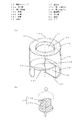
渦流発生ユニット11は図3(a)に示すように、筒状ケーシング13と、螺旋状の旋回促進面14と、流出面15とリブ22から構成されている。なお、筒状ケーシング13の中心を通る中心軸13aを図3(a)中に一点鎖線で示している。
As shown in FIG. 3A, the vortex generating unit 11 includes a
筒状ケーシング13は、その外周面の下流側(図3(a)においては上部)に、塵埃を排出するための開口となる排出口16を設けており、図2(b)に示すように、集塵室12の中に排出口16とその周辺の筒状ケーシング13が食い込むような構造となっている。
The
ここで、筒状ケーシング13の上流側(図3(a)においては下部)の構造について説明する。 Here, the structure of the upstream side of the cylindrical casing 13 (lower part in FIG. 3A) will be described.
旋回促進面14は、筒状ケーシング13の上流側の内部に配置し、その上流側の端部を始端14a、下流側の端部を終端14bとする。筒状ケーシング13を中心軸13aと垂直で始端14aを通る面で切断して出来た開口を第一の流入口17aとする。なお、始端14aよりもさらに上流側で筒状ケーシング13を切断してもよい。つまり、始端14aと筒状ケーシング13の上流側端面との間が空いた構成となっていてもよい。
The turning
次に、旋回促進面14の始端14aを含み、旋回促進面14の落差によって開口した部分を螺旋開口18とし、この螺旋開口18から旋回促進面14の旋回方向とは反対方向に90度の範囲を、筒状ケーシング13の側面側から見て、旋回促進面14の外面側の軌跡14cが見えるように前記側面に切り欠部を設けたその開口を第二の流入口17bとする。この流入口17については、上流側から斜めに見た図3(b)で示している。また本実施の形態では、切り欠部に角が出ないように、丸みをつけている。また、切り欠く角度は螺旋開口から90度を超えていても良いが、後述する吸気ガイドの役割を担うため、大きくても180度の範囲内となる。
Next, a portion including the start end 14 a of the turning
螺旋開口18は、旋回促進面14の始端14aと終端14bの対向するそれぞれの一辺と、旋回促進面14の中心部分にある、中心軸13aに沿った中心棒19による一辺と、筒状ケーシングの側面上の旋回促進面14の始端14aと終端14bの端部を結んだ一辺の四辺により構成される。なお、本実施の形態では、旋回促進面14は360度の螺旋形状であるが、360度以上であってもよく、その場合、旋回促進面14の終端14bの一辺が螺旋開口18の一辺ではなく、旋回促進面14の始端14aから終端14bまでの間の面上となる。
The
また、旋回促進面14は360度未満であって、筒状ケーシング13の上流側から旋回促進面14を見た平面視において、始端14aと終端14bの間の隙間が数mm程度存在していてもよい。こうすることで、旋回促進面14を金型で樹脂成型する場合に、螺旋開口18部分で金型同士が接触するための抜き勾配を取ることができ、製造を容易にすることができる。
Further, the turning
また、旋回促進面14は、その中心に螺旋状の面と接合された中心棒19を備えており、構造的に旋回促進面14支えることで強度を増している。中心棒19は、円柱状であり、下流側の端部はドーム形状とすることで、断面の急激な変化を抑え、圧力損失の増加を抑制している。なお本実施の形態では、この中心棒19は旋回促進面14の始端14aから終端14bまでの長さとなっているが、旋回促進面14の始端14aから流出面15まで延ばしてもよい。その場合、旋回促進面14の終端14bから流出面15までの間で、流出面15に向うにつれ徐々に中心棒19の直径を大きくするような形状としてもよい。こうすることで、空気の流れる空間が徐々に狭まり、空気の旋回する速さが増し、遠心力が増加し、集塵性能がよくなる。
Further, the turning
次に、流出面15は筒状ケーシング13の下流側に蓋をした形状のものであり、流出面と同心円で流出口21が開口している。この流出口21は筒状ケーシング13よりも小さい円である。
Next, the
そして、リブ22は、流出口21の端部から上流側に向かって突出した形状となっており、このリブ22の突出長さRは、筒状ケーシング13の直径φの0.01〜0.2倍の長さが望ましく、本実施の形態では、0.1倍の突出長さとなっている。
The
このリブ22は、旋回流が流出口21を通って下流側へ流れる時に、塵埃が下流側へ流れていく際の抵抗となるため、捕集性能をより向上させることができる。突出長さRは0.2倍を超えた長さにすると、気流そのものへの抵抗となってしまい、圧力損失を増大させてしまう。なお、リブ22がなくても塵埃の捕集は可能である。
Since this
流出面15は、筒状ケーシング13の内径よりも小さい開口を有した形状となっており、この開口が渦流発生ユニット11の流出口21となる。本実施の形態では、筒状ケーシング13の軸に垂直となるように流出面15があるが、この流出面15は、例えば、中央に向かってなだらかに、上流側(図3(a)において下側)に向かって傾斜していてもよい。
The
次に集塵室12について説明する。 Next, the dust collection chamber 12 will be described.
すでに説明したが集塵室12は、四角箱型形状であり、そのうちの1つの側面と渦流発生ユニット11が接続される。加えて、渦流発生ユニット11の排出口16が集塵室12の中に入り込むように接続している。なお、集塵室12の複数の面と渦流発生ユニットが接続されてもよい。集塵室12は、渦流発生ユニット11を除いて空気の出入りがないような、密閉構造となっている。また、集塵室12の容積はできる限り大きくしたほうが良い。容積が小さいと堆積した塵埃が巻き上げられ、渦流発生ユニット11に戻る再飛散現象が発生しやすくなるからである。本実施の形態では、渦流発生ユニット11の軸方向の長さと集塵室12の高さを同じとした。 As already described, the dust collection chamber 12 has a square box shape, and one side of the dust collection chamber 12 is connected to the eddy current generating unit 11. In addition, the discharge port 16 of the vortex generating unit 11 is connected so as to enter the dust collection chamber 12. Note that a plurality of surfaces of the dust collection chamber 12 and the eddy current generating unit may be connected. The dust collection chamber 12 has a sealed structure so that air does not enter and exit except for the vortex generating unit 11. The volume of the dust collection chamber 12 should be as large as possible. This is because if the volume is small, the accumulated dust is wound up and a re-scattering phenomenon that returns to the vortex generating unit 11 is likely to occur. In the present embodiment, the axial length of the vortex generating unit 11 and the height of the dust collecting chamber 12 are the same.
さらに、排出口16と接続した集塵室12の一面は、排出口16近傍で、その面の一部を傾斜させることで、排出口16付近に堆積した塵埃が、集塵室12の底面に落下しやすいような形状としている。 Further, one surface of the dust collection chamber 12 connected to the discharge port 16 is in the vicinity of the discharge port 16, and a part of the surface is inclined so that dust accumulated near the discharge port 16 is deposited on the bottom surface of the dust collection chamber 12. The shape is easy to fall.
また集塵室12は、引き出しのような二重構造となっており、内側にゴミトレー12aを備えている。ゴミトレー12aは四角箱型形状であり、天面は開口しており、排出口16を通ってきた塵埃はゴミトレー12aに堆積する。このゴミトレー12aは図1における空気浄化装置30の正面図の左側から引き出せる構造となっており、塵埃が堆積した場合、ゴミトレー12aを引き出して、簡単に塵埃を捨てることができる。
The dust collection chamber 12 has a double structure like a drawer, and has a dust tray 12a inside. The dust tray 12a has a square box shape, the top surface is open, and the dust that has passed through the discharge port 16 accumulates on the dust tray 12a. The dust tray 12a has a structure that can be pulled out from the left side of the front view of the
次に、本発明の集塵装置4における集塵の原理について説明をする。
Next, the principle of dust collection in the
空気の流れは、図3(b)の矢印で示すように、第一の流入口17aと第二の流入口17bから螺旋開口18を通り、渦流発生ユニット11の内部で旋回流が発生し、流出口21から出る。
As shown by the arrows in FIG. 3B, the air flow passes through the
この時、螺旋開口18から入った空気は、旋回促進面14に沿う流れと筒状ケーシング13の円筒の側面に沿う流れによって、図3(a)における上部方向に旋回をしながら進むこととなる。
At this time, the air that has entered from the
この際、空気中に浮遊している塵埃(重さを持った粒子または繊維)は、旋回流に載って旋回する際に筒状ケーシング13の中心から外周方向に向かう遠心力を受ける。遠心力を受けた塵埃は、筒状ケーシング13の外周方向へ向かい、その外周付近(筒状ケーシング13の内壁面付近)を旋回する。外周面に設けた排出口16付近を塵埃が通ると、塵埃には遠心力が働いているため、さらに外側へ行こうと、排出口16から筒状ケーシング13の外側へ飛び出す。
At this time, dust (particles or fibers having a weight) floating in the air receives a centrifugal force from the center of the
そして、塵埃は集塵室12内へ入る。旋回していた時の慣性力も残っており、塵埃は集塵室12内でも多少飛び続けるが、重力に引っ張られ、集塵室12内で落下する。 The dust enters the dust collection chamber 12. The inertial force at the time of turning also remains, and the dust continues to fly somewhat in the dust collection chamber 12 but is pulled by gravity and falls in the dust collection chamber 12.
集塵室12内には排出口16以外に開口部はないため、多くの空気が渦流発生ユニット11から集塵室12へ流れたり、逆に集塵室12から渦流発生ユニット11へ流れたりすることはないが、多少の空気の出入りはある。 Since there is no opening other than the discharge port 16 in the dust collection chamber 12, a large amount of air flows from the vortex generating unit 11 to the dust collecting chamber 12, or conversely, flows from the dust collecting chamber 12 to the vortex generating unit 11. There is nothing, but there is some air in and out.
渦流発生ユニット11において、塵埃は旋回しながら下流側(図3(a)においては上部)へ向かっている。流出面15を備えることで、筒状ケーシング13の内壁面近傍ではなく、もう少し中心側を旋回している塵埃があったとすると、流出面15がなければ排出口16から塵埃は排出されないが、その塵埃が流出面15に衝突すれば、それ以上は下流側へは移動できず、旋回によって遠心力は働き続けているため、流出面15に沿って筒状ケーシング13の内壁面方向へ移動し、排出口16から集塵室12へ移動する。このため、流出面15を備えると、塵埃の捕集性能を向上させることができる。
In the vortex generating unit 11, the dust is turning toward the downstream side (upper part in FIG. 3A) while turning. By providing the
塵埃が流出面15に衝突することを想定しているため、流出面15に設けた流出口21は筒状ケーシング13の内径より小さい必要がある。また塵埃は流出面15に衝突しても旋回し続けるため、流出面15の流出口21の中心が筒状ケーシング13の中心軸13a上になるように流出口21を設けた方が、塵埃が流出面15の開口すなわち流出口21から出る量を最も少なくすることができる。すなわち、捕集性能を上げることができる。
Since it is assumed that dust collides with the
排出口16は、できる限り多くの塵埃を排出させるために、旋回促進面14より下流側(図3(a)においては上側)に設けたほうが良い。塵埃が遠心力によって筒状ケーシング13の内壁面側に移動する時間が必要なため、排出口16が上流側にあると、多くの塵埃を排出できなくなってしまう。
In order to discharge as much dust as possible, the discharge port 16 should be provided on the downstream side (upper side in FIG. 3A) from the turning
塵埃の排出をより多くするために、本実施の形態において排出口16は、筒状ケーシング13の最下流側、つまり流出面15と接触する部分に設けている。これにより、塵埃が遠心力を受けて筒状ケーシング13の内壁面側に移動する時間をできるだけ稼げるため、塵埃が排出口16から出る量を増やせるとともに、流出面15に衝突して筒状ケーシング13の内壁面側へ移動してきた塵埃もスムーズに排出口16から出すことができるため、捕集性能をより高めることができる。なお、排出口16の形状は、四角形状となっているが、これに限定されるものではない。
In this embodiment, the discharge port 16 is provided at the most downstream side of the
次に、螺旋開口18部分の空気の流れについて説明をする。
Next, the air flow in the
旋回促進面14が、下流側(図3(a)においては上部)に向かいながら、螺旋状の面を描いており、螺旋開口18から入った空気は旋回促進面14によって、スムーズに下流側(図3(a)においては上部)へ向かう流れに変わりながら、筒状ケーシング13の内壁によって、スムーズに旋回する流れへと変化する。つまり、螺旋開口18から入った空気の流れはスムーズに下流側への方向性を持った旋回流となっている。
The
これにより、流入気流と旋回気流が干渉することが無いため、圧力損失を低く抑えることができる。さらに、螺旋開口18が筒状ケーシング13から飛び出す構造ではなはなく、旋回促進面14と筒状ケーシング13とで一体となっていることで、流入のための余分なスペースやそれを構成する部材が必要とならず、小型な渦流発生ユニット11となる。
Thereby, since an inflow air current and a turning air current do not interfere, a pressure loss can be suppressed low. In addition, the
さらに、本発明においては螺旋開口18の幅を自由に設定することができることが特徴であり、中心棒19側へ大きく広げることができる。すなわち、中心棒19の径により、螺旋開口18の幅を自由に設定することができ、中心棒19の径を小さくする、または中心棒19を使用しないことにより、螺旋開口18の幅を大きくすることができる。これにより、螺旋開口18の面積が広くなることで、風速を遅くすることができ、流入による圧力損失を低減することができる。
Furthermore, the present invention is characterized in that the width of the
次に、本発明のポイントとなる第一の流入口17a、第二の流入口17b部分について説明をする。 Next, the 1st inflow port 17a and the 2nd inflow port 17b part used as the point of this invention are demonstrated.
第一の流入口17aは、筒状ケーシング13と同じ面積である。これに加え、側面の切り欠部が第二の流入口17bとなる。渦流発生ユニット11によって処理される空気は、これらの流入口17を通ってくるため、それらの面積は広く、流入速度は低減され、圧力損失を低く抑えることができる。
The first inflow port 17 a has the same area as the
また、本実施の形態のように複数の渦流発生ユニット11を並べて使用する際、図2(a)の正面図に示すように、流出面15と、第一の流入口17aを同一側になるように隣接配置し、さらに、渦流発生ユニット11の少なくとも一つの螺旋開口18は、隣接する他の渦流発生ユニット11の側面と接触するように配置する構成にすると以下の作用が創出できる。
Further, when a plurality of eddy current generating units 11 are used side by side as in the present embodiment, as shown in the front view of FIG. 2A, the
螺旋開口18を中心に見た場合、そこに流入しようとする空気は、隣接した渦流発生ユニット11の側面によって、徐々に絞られる構造となっている。特に、筒状ケーシング13内の旋回流は外周側が強い。螺旋開口18において、外周側にあたる一辺が何も無い状態であると、その一辺を後ろ側から回り込んで入ろうとする空気などで圧力損失が増加してしまう。
When viewed from the center of the
本発明の渦流発生ユニット11では、前記一辺は、隣接した渦流発生ユニット11の側面が正接配置されており、口を開くように、外側に広がる湾曲した構造とすることで、回り込んで入ろうとする空気が無く、また螺旋開口18に向けて緩やかに断面積が小さく変化するために、圧力損失を大きく低減することができる。
In the eddy current generating unit 11 according to the present invention, the side of the adjacent eddy current generating unit 11 is tangentially arranged on the one side, and a curved structure that spreads outward so as to open the mouth is likely to enter. Since there is no air to perform and the cross-sectional area changes gradually toward the
さらに、図2(a)の正面図において、渦流発生ユニット11の手前にある塵埃が、螺旋開口18へ向かって流れて行くときに、第二の流入口17bを通って螺旋開口18に入るものと螺旋開口18同士の間の筒状ケーシング13の側面に向かって進むものがある。本発明において、螺旋開口18同士の間の面は筒状ケーシング13と同様の径で滑らかに湾曲した円弧状になっており、その湾曲した側面に衝突した塵埃は、隣の渦流発生ユニット11の第二の流入口17bを通り、螺旋開口18に流入する。これにより、より確実に空気中に浮遊している塵埃を渦流発生ユニット11に取り込むことができ、捕集効率を向上させることができる。
Furthermore, in the front view of FIG. 2A, when dust in front of the vortex generating unit 11 flows toward the
図2(a)に示すように複数の渦流発生ユニット11を隣接配置した場合、螺旋開口18が他の渦流発生ユニット11の側面と接触しない場合がある。図2(a)の正面図においては、右端の螺旋開口18がそれである。この場合、他の螺旋開口18と同様に、圧力損失を低減するために、筒状ケーシング13の側面上の一辺に外側に広がる湾曲した吸気ガイドを設けることで、全ての渦流発生ユニット11において同様に圧力損失を低減することができる。なお、図2(a)における右端以外の渦流発生ユニット11も、隣接した渦流発生ユニット11の側面が吸気ガイドの役目を果たしている。
When a plurality of eddy current generation units 11 are arranged adjacent to each other as shown in FIG. 2A, the
以上の集塵装置4を図1の説明で前述したように空気浄化装置30の吸気口2部分に備えることで、集塵装置4で、目に見えるような粗塵を捕集し、より細かい塵埃をエアフィルタ5で捕集する空気浄化装置30において、エアフィルタ5への目詰まりを遅らせることができ、エアフィルタ5を長期間使用し続けることが可能となる。
As described above with reference to FIG. 1, the
もし、本発明の集塵装置4を備えていない場合、エアフィルタ5の前面に粗塵が堆積し、目詰まりが発生し、風量が低下して、空気浄化装置30としての能力が低下する。そのため、定期的にエアフィルタ5の前面に堆積した粗塵を除去する必要があった。例えば、掃除機などを使用して堆積した塵埃を除去していた。
If the
しかし、本集塵装置4で粗塵を回収すれば、ゴミトレー12aに堆積していくため、ある程度堆積した時点で、ゴミトレー12aを引き出し、捨てるだけでよいので、メンテナンス性が大幅に向上する空気浄化装置30を提供することができる。さらに、家庭での使用を想定すると、空気浄化装置30から発生する騒音はできる限り抑える必要がある。
However, if coarse dust is collected by the
そのため、本発明の集塵装置4を用いれば、圧力損失が低いため、送風機の動力が少なくてすみ、騒音を抑えることができる。
Therefore, if the
また、空気浄化装置30は、前述したように風量が変化する。風量が変化したときにおいても、集塵装置4における捕集効率を維持するために、渦流発生ユニット11を複数備えている。
Further, as described above, the air volume of the
こうすることで、風量に応じて渦流発生ユニット11の使用個数を変化させることができ、低風量時でも十分な旋回流を得る事ができ、捕集効率が維持できる。なお、使用個数の変化方法は、例えば、流出口をダンパで塞ぐなどが考えられる。 In this way, the number of vortex generator units 11 used can be changed according to the air volume, and a sufficient swirling flow can be obtained even at a low air volume, and the collection efficiency can be maintained. As a method of changing the number of used units, for example, closing the outlet with a damper can be considered.
なお、本実施の形態では、渦流発生ユニット11の向きは、中心軸13aが垂直方向となり、流出口が上側であったが、上下逆でも良く、さらに中心軸が水平方向の向きであってもよい。
In the present embodiment, the direction of the vortex generating unit 11 is such that the
本発明にかかる集塵装置は、圧力損失を低く抑えることができるものであるので、動力を低減することができ、騒音を抑えられるため、塵埃を分離・捕集する集塵装置等および、室内用の空気浄化装置等として有用である。 Since the dust collector according to the present invention can suppress pressure loss to a low level, power can be reduced, and noise can be suppressed. Therefore, a dust collector that separates and collects dust, It is useful as an air purification device for use.
1 本体
2 吸気口
3 排気口
4 集塵装置
5 エアフィルタ
6 脱臭フィルタ
7 加湿フィルタ
7a 水トレー
8 送風手段
9 操作部
10 制御部
11 渦流発生ユニット
12 集塵室
12a ゴミトレー
13 筒状ケーシング
13a 中心軸
14 旋回促進面
14a 始端
14b 終端
14c 軌跡
15 流出面
16 排出口
17 流入口
17a 第一の流入口
17b 第二の流入口
18 螺旋開口
19 中心棒
20 吸気ガイド
21 流出口
22 リブ
30 空気浄化装置
31 キャスター
DESCRIPTION OF
Claims (4)
A body having an intake port outlet, and blower means in said body, an air purification device provided with a dust collecting device in blast path for flowing the air by the blowing means, the dust collecting apparatus, the intake A cylindrical casing having an air inlet at one end of a cylinder on the upstream side in the air passage communicating with the opening, an air outlet at the other end on the downstream side, and a dust outlet on the outer periphery of the cylinder; An eddy current generating unit, and a dust collecting chamber for storing dust separated by the eddy current generating unit and discharged from the discharge port, the eddy current generating unit in the cylindrical casing on the inlet side, It comprises a turning promotion surface that turns spirally around the central axis of the cylindrical casing, includes a start end that is an upstream end of the turning promotion surface, and forms a spiral opening by a drop in the axial direction. What is the turning direction of the turning promotion surface from the spiral opening? A range of at least 90 degrees in the opposite direction is provided with a notch on the side surface so that the trajectory on the outer surface side of the turning promotion surface can be seen when viewed from the side surface side of the cylindrical casing. In addition to the surface constituted by the upstream end face of the cylindrical casing, the notch is also used as an inlet, and air containing dust is taken in from the inlet of the dust collector air, and the vortex flow of the dust collector is generated. An air purifying apparatus characterized in that air from which dust has been removed by a unit is blown out from the exhaust port.
Priority Applications (1)
| Application Number | Priority Date | Filing Date | Title |
|---|---|---|---|
| JP2013199527A JP6178983B2 (en) | 2013-09-26 | 2013-09-26 | Dust collector and air purifier using the same |
Applications Claiming Priority (1)
| Application Number | Priority Date | Filing Date | Title |
|---|---|---|---|
| JP2013199527A JP6178983B2 (en) | 2013-09-26 | 2013-09-26 | Dust collector and air purifier using the same |
Publications (2)
| Publication Number | Publication Date |
|---|---|
| JP2015062879A JP2015062879A (en) | 2015-04-09 |
| JP6178983B2 true JP6178983B2 (en) | 2017-08-16 |
Family
ID=52831256
Family Applications (1)
| Application Number | Title | Priority Date | Filing Date |
|---|---|---|---|
| JP2013199527A Active JP6178983B2 (en) | 2013-09-26 | 2013-09-26 | Dust collector and air purifier using the same |
Country Status (1)
| Country | Link |
|---|---|
| JP (1) | JP6178983B2 (en) |
Families Citing this family (2)
| Publication number | Priority date | Publication date | Assignee | Title |
|---|---|---|---|---|
| JP6653414B2 (en) * | 2015-09-28 | 2020-02-26 | パナソニックIpマネジメント株式会社 | Dust collector |
| EP3939853A4 (en) * | 2019-03-13 | 2022-12-07 | Hitachi, Ltd. | Ventilator for railroad vehicle |
Family Cites Families (4)
| Publication number | Priority date | Publication date | Assignee | Title |
|---|---|---|---|---|
| JPS49100656A (en) * | 1973-01-27 | 1974-09-24 | ||
| JP2004129783A (en) * | 2002-10-09 | 2004-04-30 | Toshiba Tec Corp | Vacuum cleaner |
| AU2006200234B2 (en) * | 2005-07-12 | 2008-06-05 | Samsung Electronics Co., Ltd. | Dust separating apparatus |
| KR101250077B1 (en) * | 2006-04-04 | 2013-04-02 | 엘지전자 주식회사 | Dust collecting unit of vacuum cleaner |
-
2013
- 2013-09-26 JP JP2013199527A patent/JP6178983B2/en active Active
Also Published As
| Publication number | Publication date |
|---|---|
| JP2015062879A (en) | 2015-04-09 |
Similar Documents
| Publication | Publication Date | Title |
|---|---|---|
| US20220378259A1 (en) | Handheld vacuum cleaner | |
| JP5126273B2 (en) | Cyclone separation device and vacuum cleaner | |
| JP2006289171A (en) | Air cleaner | |
| JP6225329B2 (en) | Dust collector and air purifier using the same | |
| WO2006100976A1 (en) | Air cleaner | |
| CN102525350A (en) | Vacuum cleaner | |
| JP4315963B2 (en) | Cyclone dust collector | |
| JP6178983B2 (en) | Dust collector and air purifier using the same | |
| JP3854215B2 (en) | Cyclone dust collector | |
| CN202477550U (en) | Vacuum cleaner | |
| JP2006205168A5 (en) | ||
| JP2005524819A (en) | Device for effective separation of airborne particles from airflow | |
| JP2004129783A (en) | Vacuum cleaner | |
| JP2008520424A (en) | Purification unit for wet air purifier | |
| CN102670132A (en) | Cyclone separation dust collecting device | |
| WO2014141614A1 (en) | Dust-catching device and air cleaning device using same | |
| JP2002349918A (en) | Air cleaner | |
| JP2012249824A (en) | Vacuum cleaner | |
| JP5077473B1 (en) | Cyclone separation device and vacuum cleaner | |
| JP4968313B2 (en) | Electric vacuum cleaner | |
| JP4941537B2 (en) | Electric vacuum cleaner | |
| CN101732001A (en) | Dust collecting barrel of suction cleaner | |
| JP7442040B2 (en) | air purifier | |
| JP4708069B2 (en) | Air cleaner | |
| JP5077371B2 (en) | Cyclone separation device and vacuum cleaner |
Legal Events
| Date | Code | Title | Description |
|---|---|---|---|
| A711 | Notification of change in applicant |
Free format text: JAPANESE INTERMEDIATE CODE: A711 Effective date: 20150312 |
|
| RD01 | Notification of change of attorney |
Free format text: JAPANESE INTERMEDIATE CODE: A7421 Effective date: 20160519 |
|
| A621 | Written request for application examination |
Free format text: JAPANESE INTERMEDIATE CODE: A621 Effective date: 20160906 |
|
| A977 | Report on retrieval |
Free format text: JAPANESE INTERMEDIATE CODE: A971007 Effective date: 20170410 |
|
| A131 | Notification of reasons for refusal |
Free format text: JAPANESE INTERMEDIATE CODE: A131 Effective date: 20170418 |
|
| A521 | Written amendment |
Free format text: JAPANESE INTERMEDIATE CODE: A523 Effective date: 20170427 |
|
| A131 | Notification of reasons for refusal |
Free format text: JAPANESE INTERMEDIATE CODE: A131 Effective date: 20170523 |
|
| A521 | Written amendment |
Free format text: JAPANESE INTERMEDIATE CODE: A523 Effective date: 20170525 |
|
| TRDD | Decision of grant or rejection written | ||
| A01 | Written decision to grant a patent or to grant a registration (utility model) |
Free format text: JAPANESE INTERMEDIATE CODE: A01 Effective date: 20170606 |
|
| A61 | First payment of annual fees (during grant procedure) |
Free format text: JAPANESE INTERMEDIATE CODE: A61 Effective date: 20170619 |
|
| R151 | Written notification of patent or utility model registration |
Ref document number: 6178983 Country of ref document: JP Free format text: JAPANESE INTERMEDIATE CODE: R151 |