JP6178552B2 - Cushion material and manufacturing method thereof - Google Patents
Cushion material and manufacturing method thereof Download PDFInfo
- Publication number
- JP6178552B2 JP6178552B2 JP2012182716A JP2012182716A JP6178552B2 JP 6178552 B2 JP6178552 B2 JP 6178552B2 JP 2012182716 A JP2012182716 A JP 2012182716A JP 2012182716 A JP2012182716 A JP 2012182716A JP 6178552 B2 JP6178552 B2 JP 6178552B2
- Authority
- JP
- Japan
- Prior art keywords
- support
- cushion
- protruding
- cushion body
- section
- Prior art date
- Legal status (The legal status is an assumption and is not a legal conclusion. Google has not performed a legal analysis and makes no representation as to the accuracy of the status listed.)
- Active
Links
Images


Landscapes
- Mattresses And Other Support Structures For Chairs And Beds (AREA)
Description
この発明は、マットレスなどに用いられるクッション材およびその製造方法に関するものである。 The present invention relates to a cushion material used for a mattress and the like and a method for manufacturing the same.
例えばマットレスは、上下の2枚の板状クッション材の間に多数のコイルスプリングを配列して、上側の板状クッション材からの荷重を各コイルスプリングで弾力的に受け止めるよう構成されている。しかし、コイルスプリングは、バネ鋼等から形成された金属製であり、ウレタンフォーム製の板状クッション材とは材質が異なるため、当該マットレスの廃棄処分時には板状クッション材とコイルスプリングとを分別しなければならず、廃棄作業が面倒で、かつ煩わしい。 For example, the mattress is configured so that a large number of coil springs are arranged between two upper and lower plate-shaped cushion materials, and the load from the upper plate-shaped cushion material is elastically received by each coil spring. However, the coil spring is made of metal made of spring steel, etc., and the material is different from the urethane foam plate cushion material. Therefore, when the mattress is disposed of, the plate cushion material and the coil spring are separated. It must be cumbersome and cumbersome.
近年では、前記金属製のコイルスプリングの代替部材として、樹脂発泡体のみから形成されたクッション材が実用化されている。例えば特許文献1のクッション材は、板状のベース部に根元部分と比べて先端部が膨らんだ所謂きのこ形状の突起を設けることで、この突起によって荷重を支持するようになっている。しかしながら、特許文献1のクッション材は、膨らんだ先端部により体圧分散性を向上できるものの、圧縮の初期段階で圧縮荷重が低く、更に圧縮すると緩やかに圧縮荷重が上昇する前記コイルスプリングの如き好適なクッション感が十分に得られるとは云えず、更なる改良が求められている。また、特許文献1のクッション材は、突起の形状が複雑なので、二次元裁断加工や熱線加工などによって立体的に裁断しなければならず、また突起が所謂アンダーカット形状になっているのでモールド成形を採用することができない。
In recent years, a cushion material formed only from a resin foam has been put to practical use as an alternative to the metal coil spring. For example, the cushion material disclosed in
すなわち本発明は、従来の技術に係るクッション材およびその製造方法に内在する前記問題に鑑み、これらを好適に解決するべく提案されたものであって、ほどよいクッション感を得られるクッション材およびその製造方法を提供することを目的とする。 That is, the present invention has been proposed in order to suitably solve these problems inherent in the conventional cushioning material and the manufacturing method thereof, and a cushioning material capable of obtaining a moderate cushioning feeling and the cushioning material. An object is to provide a manufacturing method .
前記課題を克服し、所期の目的を達成するため、本願の請求項1に係る発明のクッション材は、
弾力性を有する発泡体からなり、複数のクッション体が突出形成されたクッション材において、
前記クッション体は、全体として外面の傾斜角度が異なる裁頭円錐形状部をなす支持基部と支持端部とを柱状の支持胴部で繋いだ形状を有すると共に、
該クッション体の根元側に設けられ、該根元側から突出端面側に向かうにつれて、該クッション体の突出方向と直交する方向に破断した支持断面が小さくなるよう傾斜する外面に形成された前記支持基部と、
該支持基部の突出端面側に連ねて設けられた前記支持胴部と、
前記支持胴部から前記突出端面にかけて設けられ、根元側から突出端面側に向かうにつれて支持断面が小さくなるように形成された前記支持端部とを備え、
前記支持胴部は、突出方向において支持断面が一定になる部分を有すると共に、支持断面が根元側から突出端面側に向かうにつれて小さくなる先細り形状であって、その変化率が前記支持基部および前記支持端部よりも小さくなるように形成されていることを要旨とする。
請求項1に係る発明によれば、クッション体における突出端側の支持断面が比較的小さく形成されているので、圧縮初期段階の反発を抑えることができる。また、クッション体における根元側の支持断面が比較的大きく形成されているので、クッション体を圧縮するような大きな荷重をかけても底付きするのを防止できる。支持胴部は、突出方向において支持断面が一定に形成されるので、圧縮に対する荷重変化を一定の比率に近付けることができ、好適なクッション感を得ることができる。更に支持胴部は、根元側から突出端面側に向かうにつれて小さくなる支持断面の変化率が支持基部および支持端部よりも小さくなるように形成されるので、圧縮に対する荷重変化を一定の比率に近付けることができ、好適なクッション感を得ることができる。
In order to overcome the above-mentioned problems and achieve the intended purpose, the cushioning material of the invention according to
In the cushion material formed of a foam having elasticity, and a plurality of cushion bodies protruding,
The cushion body has a shape in which a support base portion and a support end portion, which form a truncated cone shape portion having a different inclination angle of the outer surface as a whole, are connected by a columnar support body portion,
Provided at the base side of the cushion body, toward the該根root side to the protruding end face side, the support base supporting a section broken in the direction orthogonal to the projecting direction of the cushion body is formed on an outer surface which is inclined to be smaller When,
And the support body portion provided been chosen on the projecting end face of the support base,
Said support is provided from the body portion to the projecting end face, and a said support end portion supporting section is formed to be smaller toward the root side to the protruding end face,
Said support barrel, which has a portion where the support section is constant in the protruding direction, the support section is a smaller becomes tapered toward the root side to the protruding end surface side, its rate of change the support base and the The gist is that it is formed to be smaller than the support end.
According to the first aspect of the present invention, since the support cross section on the protruding end side of the cushion body is formed to be relatively small, repulsion at the initial stage of compression can be suppressed. Further, since the support cross section on the base side of the cushion body is formed to be relatively large, it is possible to prevent bottoming even when a large load is applied to compress the cushion body. Since the support body is formed with a constant support cross section in the protruding direction, it is possible to bring the load change with respect to compression close to a constant ratio and to obtain a suitable cushion feeling. Furthermore, the support body is formed so that the rate of change of the support cross section that becomes smaller from the base side toward the projecting end surface side becomes smaller than that of the support base and the support end, so that the load change with compression approaches a certain ratio. And a suitable cushion feeling can be obtained.
請求項2に係る発明では、前記支持基部および前記支持端部は、前記突出端面の中心を前記突出方向に通る軸線に対して近づくように形成された外面を夫々有すると共に、前記支持胴部は、前記軸線に沿って延在するよう形成された外面を有することを要旨とする。
請求項2に係る発明によれば、クッション体の支持断面が急激に変化しないので、ほどよいクッション感が得られる。
In the invention according to
According to the invention which concerns on
請求項3に係る発明では、隣り合う前記クッション体の間を繋いで、該クッション体よりも低いリブが設けられたことを要旨とする。
請求項3に係る発明によれば、リブによってクッション体の横倒れを防止することがでできるから、クッション体で荷重を適切に受け止めることができる。
前記課題を克服し、所期の目的を達成するため、本願の請求項4に係る発明のクッション材の製造方法は、
弾力性を有する発泡体からなり、複数のクッション体が突出形成されたクッション材を製造するに際し、
前記クッション体を、全体として外面の傾斜角度が異なる裁頭円錐形状部をなす支持基部と支持端部とを柱状の支持胴部で繋いだ形状にすると共に、
前記クッション体の根元側に設けられ、該根元側から突出端面側に向かうにつれて、該クッション体の突出方向と直交する方向に破断した支持断面が小さくなるよう傾斜する外面に形成された前記支持基部と、該支持基部の突出端面側に連ねて設けられた前記支持胴部と、前記支持胴部から前記突出端面にかけて設けられ、根元側から突出端面側に向かうにつれて支持断面が小さくなるように形成された支持端部とから形成し、
前記支持胴部は、突出方向において支持断面が一定になる部分を有すると共に、支持断面が根元側から突出端面側に向かうにつれて小さくなる先細り形状であって、その変化率が前記支持基部および前記支持端部よりも小さくなるように形成し、
前記クッション体を含めた全体をモールド成形するようにしたことを要旨とする。
請求項4に係る発明によれば、請求項1に記載のクッション体を含めた全体をモールド成形することで、クッション材を製造することができる。
The gist of the invention according to claim 3 is that ribs that are lower than the cushion body are provided by connecting the adjacent cushion bodies.
According to the third aspect of the present invention, the rib can prevent the cushion body from falling sideways, so that the load can be appropriately received by the cushion body.
In order to overcome the above-mentioned problems and achieve the intended purpose, a method for producing a cushioning material according to claim 4 of the present application,
When producing a cushion material made of a foam having elasticity, and a plurality of cushion bodies protruding,
The cushion body has a shape in which a support base portion and a support end portion forming a truncated cone shape portion having different inclination angles of the outer surface as a whole are connected by a columnar support body portion,
Provided at the base side of the cushion body, toward the該根root side to the protruding end face side, the support base supporting a section broken in the direction orthogonal to the projecting direction of the cushion body is formed on an outer surface which is inclined to be smaller When, with the support body part which is provided been chosen on the projecting end face of the support base, provided toward the projecting end face of the support body portion, formed to the support section toward the root side to the protruding end face side is reduced is formed from has been support end,
Said support barrel, which has a portion where the support section is constant in the protruding direction, the support section is a smaller becomes tapered toward the root side to the protruding end surface side, its rate of change the support base and the Formed to be smaller than the support end,
The gist is that the entire body including the cushion body is molded.
According to the invention which concerns on Claim 4, a cushion material can be manufactured by mold-molding the whole including the cushion body of
本発明に係るクッション材によれば、ほどよいクッション感を得ることができ、また前述した製造方法により上記クッション材を好適に製造することができる。 According to the cushion material according to the present invention, a moderate cushion feeling can be obtained, and the cushion material can be suitably manufactured by the manufacturing method described above.
次に、本発明に係るクッション材およびその製造方法につき、好適な実施例を挙げて、添付図面を参照して以下に説明する。
Next, a cushioning material and a manufacturing method thereof according to the present invention will be described below with reference to the accompanying drawings, taking a preferred embodiment.
図1および図2に示す実施例1に係るクッション材10は、ベース部12の表面(一面)に突出形成された複数のクッション体14を備え、使用に際して基本的にクッション体14の突出方向(以下、単に突出方向という)にかかる荷重を弾力的に支持するよう構成される。クッション材10には、基本的に同じ形状および大きさで形成された複数のクッション体14が、突出方向と直交する方向(以下、面方向という)に並べられている。また、クッション材10は、隣り合うクッション体14,14の間を繋いで該クッション体14よりも低く形成されたリブ16を備えている。
The
前記クッション材10は、弾力性を有する発泡体からなり、ベース部12、クッション体14およびリブ16などの全体がモールド成形によって同時に形成される。すなわち、クッション材10は、ベース部12、クッション体14およびリブ16が継ぎ目なく同一の素材から一体的に形成される。また、クッション材10には、モールド成形に際して成形型の成形面に規定される面(クッション体14が突出する側の外面)に、気泡が破泡または圧縮されて空隙が少なく見掛け密度が高い層である所謂スキン層が形成されている。発泡体としては、ポリウレタンフォーム、ポリエチレン等のポリオレフィン系フォーム、ゴムスポンジ等を用いることができる。この中でも、作り易さや取り扱い性等の観点からポリウレタンフォームが最適である。また、樹脂発泡体は、発泡倍率が約10〜60倍、見かけ密度が16〜100kg/m3程度に設定されて、柔らかくて復元性(塑性変形しない)を有する軟質フォームであって、気泡が連通する連泡構造であるのが望ましい。すなわち、クッション材10は、荷重が付与された際に圧縮変形や曲げ変形などが生じ、かつ荷重が解除されると元の形状に弾性復帰するようになっている。そして、クッション材10は、単一素材で構成されているので、金属コイルと樹脂発泡体とを組み合わせて構成されるクッション材のように、廃棄時に分別を必要としない。
The
前記ベース部12は、突出方向から見た形状が矩形状に形成された板状部分であって(図1参照)、使用に際して厚み方向に荷重がかけられる。また、実施例1では、ベース部12の厚み方向の寸法が、クッション体14の突出寸法よりも薄く設定されている。クッション材10には、複数のクッション体14が規則的に配列されており、実施例1ではベース部12の長辺に沿って8つのクッション体14が一列に並ぶと共に、ベース部12の短辺に沿って4つのクッション体14が一列に並ぶように配置されている(図1および図2参照)。クッション材10では、同じ方向に一列に並ぶクッション体14同士の間隔が同じになるように配置されている。そして、クッション材10では、ベース部12の長辺に沿って隣り合うクッション体14,14の間隔と、ベース部12の短辺に沿って隣り合うクッション体14,14の間隔とが同じに設定され、隣り合う4つのクッション体14が正四角形の頂点に位置するように配置される。なお、クッション材10では、ベース部12の長辺および短辺と交差する交差方向に隣り合うクッション体14,14が、ベース部12の長辺(短辺)に沿って隣り合うクッション体14,14の間隔よりも大きな間隔で配置される。
The
前記クッション体14は、突端が面状に形成された凸状部分であり(図2および図3参照)、この突端の面(以下、突出端面20という)が円形(図1参照)に形成されている。クッション体14の突出端面20は、該クッション体14の突出方向と直交する方向(面方向)に平坦に形成され、平坦なベース部12の裏面と平行に延在している。図4または図5に示すように、クッション体14は、ベース部12に連なる根元側に設けられた支持基部22と、この支持基部22の突出端面20側に連ねて設けられた支持胴部24と、この支持胴部24から突出端面20にかけて設けられた支持端部26とを備えている。実施例1のクッション体14は、略裁頭円錐形状の支持基部22の突出端面20側に、略円柱形状の支持胴部24が連なると共に、支持胴部24の突出端面20側に略裁頭円錐形状の支持端部26が連なり、突出端側が根元側と比べて細くなっている。そして、クッション材10において、ベース部12の長辺または短辺に沿って隣り合うクッション体14,14は、支持基部22の一部が互いに繋がるように配置される一方、前記交差方向に隣り合うクッション体14は、互いに繋がらないように間をあけて配置されている。なお、クッション材10において、ベース部12、クッション体14およびリブ16が、曲面でなだらかに接続される。
The
前記支持基部22は、面方向に破断した支持断面が、根元側から突出端面20側に向かうにつれて小さくなるように形成され、根元側と比べて突出端面20側が細くなる形状になっている(図4および図5参照)。また、支持基部22は、根元側から突出端面20側に向かうにつれて、突出端面20の中心を突出方向に通る仮想的な突出軸線(軸線)に対して近づくように傾斜する外面を有し、該突出軸線を中心とした対称な形状に形成されている。このように、支持基部22は、外面を斜めに形成することで、根元側から突出端面20側に向かうにつれて支持断面が徐々に小さくなり、換言すれば突出端面20側から根元側に向かうにつれて支持断面が徐々に大きくなるよう構成される。ここで、支持基部22の外面は、突出端面20の外周縁に沿って延在するよう形成されており、突出軸線を中心とする円形の突出端面20よりも大きい円の一部をなす曲面状に形成されている。
The
前記支持胴部24は、突出方向において支持断面が一定になるよう形成されている(図4および図5参照)。支持胴部24は、突出軸線に沿って延在するように形成された外面を有し、該突出軸線を中心とした対称な形状に形成される。 ここで、支持胴部24の外面は、突出端面20の外周縁に沿って延在するよう形成されており、突出軸線を中心とする円形の突出端面20よりも大きい円の一部をなす曲面状に形成されている。なお、支持胴部24は、根元側から突出端面20側に向かうにつれて支持断面が小さくなる先細り形状に形成してもよい。支持胴部24は、先細り形状となる場合には、根元側から突出端面20側に向かうにつれて小さくなる支持断面の変化率が、支持基部22および支持端部26の支持断面の変化率より小さくなるよう設定するのがよい。
The
前記支持端部26は、面方向に破断した支持断面が、根元側から突出端面20側に向かうにつれて小さくなるように形成され、根元側と比べて突出端面20側が細くなる形状になっている(図4および図5参照)。また、支持端部26は、根元側から突出端面20側に向かうにつれて、突出軸線に対して近づくように傾斜する外面を有し、該突出軸線を中心とした対称な形状に形成されている。ここで、支持端部26の外面は、突出端面20の外周縁に沿って延在するよう形成されており、突出軸線を中心とする円形の突出端面20よりも大きい円の一部をなす曲面状に形成されている。このように、支持端部26は、外面を斜めに形成することで、根元側から突出端面20側に向かうにつれて支持断面が徐々に小さくなり、換言すれば突出端面20側から根元側に向かうにつれて支持断面が徐々に大きくなるよう構成される。
The
前記クッション体14は、支持端部26の傾斜した外面と突出軸線とがなす交角が、支持基部22の外面と突出軸線とがなす交角よりも大きくなるよう形成されている。そして、クッション体14は、支持端部26における支持断面の変化率が、支持基部22における支持断面の変化率よりも大きく設定されている。また、実施例1のクッション体14では、支持基部22の外面が円錐状に形成される一方、支持端部26の外面が外方へ膨らむ曲面状に形成されている。このように、クッション体14は、全体として外面の傾斜角度が異なる2つの裁頭円錐形状部分を柱状部分で繋いだ形状とされている(図5参照)。なお、クッション体14では、支持基部22と支持胴部24との間や、支持胴部24と支持端部26との間などの繋ぎ部分が、曲面でなだらかに接続されている。
The
前記リブ16は、ベース部12の長辺に沿って隣り合うクッション体14,14の間と、ベース部12の短辺に沿って隣り合うクッション体14,14の間との夫々に設けられ(図1参照)、ベース部12の表面から隆起するよう形成されている。リブ16は、ベース部12の長辺または短辺に沿って隣り合うクッション体14,14において支持基部22,22同士が繋がる部位に重なるよう形成される。なお、クッション材10には、交差方向に隣り合うクッション体14,14間にリブ16が設けられない。リブ16は、クッション体14の支持端部26よりも低く形成され、実施例1では支持胴部24の突出端面20側に高さが揃えられている。また、リブ16は、クッション体14への接続部分が、該接続部分でのクッション体14の幅よりも狭くなるよう形成される。すなわち、リブ16は、支持基部22に対応する根元側の幅が支持基部22の直径(突出軸線を挟んだ外面間の寸法)よりも小さく設定されると共に、支持胴部24に対応する突端側の幅が該支持胴部24の直径よりも小さく設定される。
The
前記リブ16は、ベース部12に連なる根元側の両側面が、ベース部12側から突端側に向かうにつれて互いに近づくよう傾斜形成され、これに連なる突端側の側面が突出方向に沿って延在するよう形成されている(図3参照)。また、リブ16の突端側は、クッション体14における突出端面20の直径と略同じ幅に設定され、側面における頂面に連なる部位がテーパ状になっている。更に、リブ16は、クッション体14の支持基部22に対応する高さ位置で突出方向に交差する傾斜面から突出方向に沿う垂直面に移り変わっている。
The
前記クッション材10には、隣り合う4つのクッション体14およびこれらのクッション体14を繋ぐリブ16に囲まれた凹部に臨んで、ベース部12を厚み方向に貫通する通孔18が形成されている(図1参照)。通孔18は、円形に形成されて、表側の開口縁がクッション体14における支持基部22の根元およびリブ16における側面の根元に連なっている(図3(b)参照)。このように、クッション材10は、ベース部12の表裏に連通する通孔18を有しているので、表面にスキン層を有していても、通孔18により通気性を確保することができる。
The
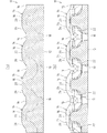
前記クッション材10は、クッション体14の突出端面20側から荷重を受ける使用態様であっても、ベース部12側から荷重を受ける使用態様であっても何れでもよい。また、クッション材10は、1枚だけであっても、2枚以上の複数枚を重ね合わせて用いてもよい。クッション材10を重ねる場合は、クッション体14の突出端面20を互いに突き当てて接合しても(図6(a)参照)、クッション体14の突出端面20をベース部12の裏面に突き当てて接合してもよい。更に、クッション体14の突出端面20を、連通気泡構造の発泡体からなる板材Pに突き合わせて接合し、板材Pとベース部12との間にクッション体14を配置する構成としてもよい(図6(b)参照)。
The
次に、実施例1に係るクッション材10の作用について説明する。クッション材10は、成形型における上方に開口したキャビティに樹脂原料を注入して、キャビティを開放したまま発泡・硬化させることで成形される。この際、クッション材10は、クッション体14を下に向けると共にベース部12を上側にして成形される。成形型のキャビティは、クッション体14に合わせて設けられたクッション体凹部や、隣り合うクッション体凹部を繋いで、リブ16に合わせて設けられたリブ凹部や、クッション体凹部の間に通孔18に合わせて設けられた空気孔凸部など有している。キャビティでは、樹脂原料を注入した際に、リブ凹部を介してクッション体凹部間に樹脂原料を流動させることができるので、支持凹部への樹脂原料の充填不良に起因するクッション体14でのボイド等の成形不良を防止できる。また、クッション材10は、クッション体14およびリブ16が先細り形状であり、突出方向と反対側に成形型から型抜きする際に干渉する所謂アンダー形状を有していない。このように、モールド成形によって、ベース部12、クッション体14、リブ16および通孔18などが一体化されたクッション材10を、簡単に形成することができる。
Next, the operation of the
一般的にウレタンフォーム等の発泡体は、気泡が発泡方向(クッション体14の突出方向に対応)に長い卵形状になるので、圧縮初期には荷重の変化に対してたわみ量の変化が少なく、圧縮弾性率(荷重変化量/たわみ変化量)が高い状態となる。その後、所定量圧縮変形されると、卵形状が球形状または扁平形状になるので、荷重の変化に対するたわみ量の変化が増加し、圧縮弾性率が低下する。これにより、荷重たわみ曲線は、上側に突出する変化点を有する曲線となる(図9参照)。クッション材10は、前記突出方向から荷重を受けた際に、支持断面が比較的小さく形成された支持端部26から潰れるので、クッション材10に荷重をかけた初期段階でクッション体14の圧縮に要する荷重を小さくすることができる。すなわち、クッション材10に荷重をかけた初期段階で、クッション体14の反発力を小さくし得るので、簡単に沈み込む柔らかいクッション感をだすことができる。クッション材10は、前記突出方向から荷重を更に受けると、支持端部26の次に支持断面が小さい支持胴部24が潰れるから、初期段階から中期段階になっても圧縮に要する荷重の急激な上昇を抑えることができると共に、適切な荷重の支持感を出すことができる。しかも、支持胴部24は、支持断面が変化しないので、圧縮に要する荷重の変化がほぼ一定比率になり、クッション体14に荷重を加えた分だけ沈み込む好適なクッション感を出すことができる。そして、クッション材10は、前記突出方向から大きく荷重を受けた際に、支持断面が比較的大きく形成された支持基部22で支持するので、底付きを防止できる。このように、クッション材10によれば、初期段階では柔らかく、中期段階では荷重に対して比例的に適度に圧縮し、圧縮が進行しても底づきしない、ほどよいクッション感を得ることができる。なお、荷重とクッション体14の圧縮との関係は、段階に応じて圧縮し易い部位を主に説明するものであり、クッション体14全体において複合的に圧縮が生じている。
In general, foams such as urethane foam have an egg shape in which the bubbles are long in the foaming direction (corresponding to the protruding direction of the cushion body 14), so there is little change in the amount of deflection with respect to the change in load at the initial stage of compression The compression elastic modulus (load change amount / deflection change amount) is high. Thereafter, when the egg is compressed and deformed by a predetermined amount, the egg shape becomes a spherical shape or a flat shape, so that the change in the deflection amount with respect to the change in the load increases and the compression elastic modulus decreases. Thus, the load deflection curve becomes a curve having a change point protruding upward (see FIG. 9). When the
前記クッション体14は、支持基部22の外面が傾斜形成されて、支持基部22が潰れる際に支持断面が徐々に変化するから、クッション特性が急激に変わることなく、適切なクッション感が得られる。同様に、クッション体14は、支持端部26の外面が傾斜形成されて、支持端部26が潰れる際に支持断面が徐々に変化するので、クッション特性が急激に変わることなく、適切なクッション感が得られる。
また、クッション体14は、支持基部22、支持胴部24および支持端部26が、突出軸線を中心とした対称な形状に形成されているから、突出方向に入力される荷重をクッション体14でバランスよく受け止めることができ、好適なクッション感を得ることができる。
The
In addition, since the
前記クッション材10は、隣り合うクッション体14,14を繋ぐリブ16によって、クッション体14の横倒れを防止することができるから、各クッション体14で荷重を適切に受け止めることができる。実施例のリブ16は、表面にスキン層を有しており、リブ16の延長方向への引張強度が向上しているため、クッション体14の横倒れ防止効果が高い。リブ16は、クッション体14よりも低く形成されているので、クッション体14においてリブ16よりも突出した部分(実施例1では支持端部26)が、リブ16や該リブ16を介して他のクッション体14からの影響を受け難く、クッション体14におけるリブ16から突出した部分を互いに独立して変形させることが可能である。すなわち、クッション材10は、クッション体14の支持端部26が独立して変形可能であるので、人体等の凹凸に合わせて独立して変形する支持端部26によって、適度に体圧を分散させて支持することができる。
Since the
図7および8に示す実施例2のクッション材30は、クッション体32の高さが実施例1のクッション体14よりも高く設定されている。実施例2のクッション材30の高さ(ベース部12の裏面からクッション体32の突出端面20までの寸法)が、実施例1のクッション材10を2枚重ねた高さと同じになっている。実施例2のクッション体32は、支持胴部24および支持端部26が実施例1と同一形状であり、支持基部22の高さが実施例1の支持基部22より高くなっている。ここで、実施例2のクッション体32は、ベース部12に連なる根元部分の支持断面が実施例1と同じであり、実施例2の支持基部22の外面と突出軸線とがなす交角が実施例1よりも小さく、ベース部12に対する傾斜が急になっている。また、実施例2のクッション材30は、リブ16が実施例1よりも高く設定されているが、該リブ16の頂面がクッション体32の支持基部22の中間部位に位置し、支持基部22の突出端面側の一部、支持胴部24および支持端部26がリブ16から突出するように構成される。なお、実施例2のクッション材30は、クッション体32およびリブ16の高さが実施例1のクッション材10より高く設定された以外は、ベース部12、クッション体32の数・配置、通孔18などの構成は実施例1と同一である。実施例2のクッション材30によれば、前述の実施例1と同様の作用効果を奏すると共に、実施例1と比べてクッション体32においてリブ16よりも突出する部分が大きく確保されているので、複数のクッション体32によって体圧を分散した状態でより好適に支持し得る。
In the
(実験例)
本発明に係るクッション体に関して圧縮たわみ荷重試験を行い、クッション特性を確認した。実験例1のクッション材は、前述した実施例2に対応するものであって、実験例1のクッション材は、10mm厚のベース部上に9個のクッション体を突出軸線が50mm間隔になるよう、縦横に配置している。実験例1のクッション体は、ベース部からの高さが60mmに設定され、突出端面の直径が15mmに設定され、各部位の寸法比率が図7および8に示した実施例2と同様である。また、実験例1のクッション材は、リブの高さがベース部から36mmに設定されている。実験例2のクッション材は、実験例1からリブを省いた構成であり、ベース部およびクッション体の構成は実験例1と同じである。比較例1のクッション材は、厚さ70mm、縦横200mmの平板である。比較例2のクッション材は、厚さ30mm、縦横200mmの平板上に、9個の半球(直径40mm)を中心が50mm間隔になるよう、縦横に配置したものである。比較例3のクッション材は、直径2.0mmの線材(硬鋼線SWB)を直径65mmとなるように巻いた高さ70mmのコイルを、中心が70mm間隔になるよう、縦横に4個並べたものである。実施例1〜2および比較例1〜2は、軟質ポリウレタンフォーム(見掛け密度:50kg/m3)から構成されている。
(Experimental example)
A compression deflection load test was performed on the cushion body according to the present invention to confirm cushion characteristics. The cushion material of Experimental Example 1 corresponds to Example 2 described above, and the cushion material of Experimental Example 1 has nine cushion bodies on a 10 mm-thick base portion so that the projecting axes are spaced by 50 mm. , Arranged vertically and horizontally. In the cushion body of Experimental Example 1, the height from the base portion is set to 60 mm, the diameter of the protruding end surface is set to 15 mm, and the dimensional ratio of each part is the same as that of Example 2 shown in FIGS. . In the cushion material of Experimental Example 1, the rib height is set to 36 mm from the base portion. The cushion material of Experimental Example 2 has a configuration in which ribs are omitted from Experimental Example 1, and the configuration of the base portion and the cushion body is the same as that of Experimental Example 1. The cushion material of Comparative Example 1 is a flat plate having a thickness of 70 mm and a length and width of 200 mm. The cushion material of Comparative Example 2 is configured by arranging nine hemispheres (
圧縮たわみ荷重試験は、JIS K6400−2 B法に基づいて行った。4つのクッション体(コイル)の中央部をφ200の円板によって75%まで圧縮した。なお、圧縮たわみ荷重試験では、予備圧縮を行っていない。実験例および比較例の夫々について、たわみ量(%)と荷重(N)との関係を図9に示す。 The compression deflection load test was performed based on the JIS K6400-2 B method. The central part of the four cushion bodies (coils) was compressed to 75% with a disc of φ200. In the compression deflection load test, preliminary compression is not performed. FIG. 9 shows the relationship between the deflection amount (%) and the load (N) for each of the experimental example and the comparative example.
図9に示すように、実験例1および2のクッション材は、圧縮初期段階において、比較例1のよう急激に荷重が大きくなることはなく、比較例2の金属コイルと同等以上に、圧縮初期段階における荷重を抑制し得ることが確認できる。 As shown in FIG. 9, in the cushioning materials of Experimental Examples 1 and 2, in the initial stage of compression, the load does not increase abruptly as in Comparative Example 1, and the initial compression state is equal to or higher than that of the metal coil of Comparative Example 2. It can be confirmed that the load at the stage can be suppressed.
(変更例)
本発明は実施例の構成に限定されるものではなく、例えば、以下のようにも変更実施可能である。また、実施例および以下の変更例に限らず、本発明の主旨の範囲内において種々の実施形態を採用し得る。
(1)本発明に係るクッション材は、マットレス、ソファ、座布団、枕など、様々なものに用いることができる。
(2)クッション体の外面は、傾斜形成する構成に限られず、階段状に形成することで支持断面を変化させてもよい。
(3)リブを省略することも可能である。
(4)実施例では、隣り合うクッション体を一部が互いに繋がるように構成したが、隣り合うクッション体を離して配置して、互いに独立する構成としてもよい。
(Example of change)
The present invention is not limited to the configuration of the embodiment, and can be modified as follows, for example. Further, the present invention is not limited to the examples and the following modifications, and various embodiments can be adopted within the scope of the gist of the present invention.
(1) The cushion material according to the present invention can be used for various materials such as a mattress, a sofa, a cushion, and a pillow.
(2) The outer surface of the cushion body is not limited to the configuration in which the cushion body is formed to be inclined, and the support cross section may be changed by forming it in a step shape.
(3) The rib can be omitted.
(4) In the embodiment, the adjacent cushion bodies are configured so as to be partially connected to each other. However, the adjacent cushion bodies may be arranged apart from each other and independent from each other.
14,32 クッション体,16 リブ,20 突出端面,22 支持基部
24 支持胴部,26 支持端部
14,32 Cushion body, 16 rib, 20 projecting end face, 22
Claims (4)
前記クッション体は、全体として外面の傾斜角度が異なる裁頭円錐形状部をなす支持基部と支持端部とを柱状の支持胴部で繋いだ形状を有すると共に、
該クッション体の根元側に設けられ、該根元側から突出端面側に向かうにつれて、該クッション体の突出方向と直交する方向に破断した支持断面が小さくなるよう傾斜する外面に形成された前記支持基部と、
該支持基部の突出端面側に連ねて設けられた前記支持胴部と、
前記支持胴部から前記突出端面にかけて設けられ、根元側から突出端面側に向かうにつれて支持断面が小さくなるように形成された前記支持端部とを備え、
前記支持胴部は、突出方向において支持断面が一定になる部分を有すると共に、支持断面が根元側から突出端面側に向かうにつれて小さくなる先細り形状であって、その変化率が前記支持基部および前記支持端部よりも小さくなるように形成されている
ことを特徴とするクッション材。 In the cushion material formed of a foam having elasticity, and a plurality of cushion bodies protruding,
The cushion body has a shape in which a support base portion and a support end portion, which form a truncated cone shape portion having a different inclination angle of the outer surface as a whole, are connected by a columnar support body portion,
Provided at the base side of the cushion body, toward the該根root side to the protruding end face side, the support base supporting a section broken in the direction orthogonal to the projecting direction of the cushion body is formed on an outer surface which is inclined to be smaller When,
And the support body portion provided been chosen on the projecting end face of the support base,
Said support is provided from the body portion to the projecting end face, and a said support end portion supporting section is formed to be smaller toward the root side to the protruding end face,
Said support barrel, which has a portion where the support section is constant in the protruding direction, the support section is a smaller becomes tapered toward the root side to the protruding end surface side, its rate of change the support base and the A cushioning material, wherein the cushioning material is formed to be smaller than a support end.
前記クッション体を、全体として外面の傾斜角度が異なる裁頭円錐形状部をなす支持基部と支持端部とを柱状の支持胴部で繋いだ形状にすると共に、
前記クッション体の根元側に設けられ、該根元側から突出端面側に向かうにつれて、該クッション体の突出方向と直交する方向に破断した支持断面が小さくなるよう傾斜する外面に形成された前記支持基部と、該支持基部の突出端面側に連ねて設けられた前記支持胴部と、前記支持胴部から前記突出端面にかけて設けられ、根元側から突出端面側に向かうにつれて支持断面が小さくなるように形成された支持端部とから形成し、
前記支持胴部は、突出方向において支持断面が一定になる部分を有すると共に、支持断面が根元側から突出端面側に向かうにつれて小さくなる先細り形状であって、その変化率が前記支持基部および前記支持端部よりも小さくなるように形成し、
前記クッション体を含めた全体をモールド成形するようにした
ことを特徴とするクッション材の製造方法。 When producing a cushion material made of a foam having elasticity, and a plurality of cushion bodies protruding,
The cushion body has a shape in which a support base portion and a support end portion forming a truncated cone shape portion having different inclination angles of the outer surface as a whole are connected by a columnar support body portion,
Provided at the base side of the cushion body, toward the該根root side to the protruding end face side, the support base supporting a section broken in the direction orthogonal to the projecting direction of the cushion body is formed on an outer surface which is inclined to be smaller When, with the support body part which is provided been chosen on the projecting end face of the support base, provided toward the projecting end face of the support body portion, formed to the support section toward the root side to the protruding end face side is reduced is formed from has been support end,
Said support barrel, which has a portion where the support section is constant in the protruding direction, the support section is a smaller becomes tapered toward the root side to the protruding end surface side, its rate of change the support base and the Formed to be smaller than the support end,
A method for manufacturing a cushion material, wherein the entire body including the cushion body is molded.
Priority Applications (1)
| Application Number | Priority Date | Filing Date | Title |
|---|---|---|---|
| JP2012182716A JP6178552B2 (en) | 2012-08-21 | 2012-08-21 | Cushion material and manufacturing method thereof |
Applications Claiming Priority (1)
| Application Number | Priority Date | Filing Date | Title |
|---|---|---|---|
| JP2012182716A JP6178552B2 (en) | 2012-08-21 | 2012-08-21 | Cushion material and manufacturing method thereof |
Publications (2)
| Publication Number | Publication Date |
|---|---|
| JP2014039615A JP2014039615A (en) | 2014-03-06 |
| JP6178552B2 true JP6178552B2 (en) | 2017-08-09 |
Family
ID=50392433
Family Applications (1)
| Application Number | Title | Priority Date | Filing Date |
|---|---|---|---|
| JP2012182716A Active JP6178552B2 (en) | 2012-08-21 | 2012-08-21 | Cushion material and manufacturing method thereof |
Country Status (1)
| Country | Link |
|---|---|
| JP (1) | JP6178552B2 (en) |
Families Citing this family (3)
| Publication number | Priority date | Publication date | Assignee | Title |
|---|---|---|---|---|
| JP2016000604A (en) * | 2014-06-12 | 2016-01-07 | 本田技研工業株式会社 | Vehicle seat pad and method of manufacturing the same |
| JP6942579B2 (en) * | 2017-09-20 | 2021-09-29 | 株式会社イノアックコーポレーション | Cushion material |
| JP7560957B2 (en) * | 2020-04-28 | 2024-10-03 | 株式会社アーケム | Cushioning material, laminated cushioning material, and method for manufacturing cushioning material |
Family Cites Families (13)
| Publication number | Priority date | Publication date | Assignee | Title |
|---|---|---|---|---|
| JPS5528133Y2 (en) * | 1978-01-18 | 1980-07-04 | ||
| US5160785A (en) * | 1991-06-11 | 1992-11-03 | E. R. Carpenter Company, Inc. | Padding body |
| CA2090643A1 (en) * | 1993-03-01 | 1994-09-02 | Paul W. Reinhardt | Contourable pocket foam mattress and method of manufacture |
| JP3025612U (en) * | 1995-09-28 | 1996-06-21 | マテリアルサイエンス株式会社 | Bedsore prevention mat |
| DE69603976T2 (en) * | 1995-12-22 | 2000-04-06 | Hoechst Celanese Corp. | VEHICLE SEAT WITH HIGH AIR CIRCULATION AND MATERIALS USED IN IT |
| JP2003235688A (en) * | 2002-02-14 | 2003-08-26 | Kuraray Medical Inc | Cushion material |
| JP3704646B2 (en) * | 2002-03-29 | 2005-10-12 | 正雄 越中屋 | Cushion material |
| JP4221952B2 (en) * | 2002-05-28 | 2009-02-12 | アイシン精機株式会社 | Elastic unit and mattress |
| JP2007111423A (en) * | 2005-10-24 | 2007-05-10 | Toyo Tire & Rubber Co Ltd | Mattress cushion material |
| CA2922187C (en) * | 2006-05-05 | 2020-06-02 | Nubatech Inc. | Cushioning structures for body parts |
| JP5189327B2 (en) * | 2007-08-24 | 2013-04-24 | 株式会社イノアックコーポレーション | Cushion body for automobile seat |
| JP2009078142A (en) * | 2007-09-06 | 2009-04-16 | Bridgestone Corp | Vehicular seat pad and its manufacturing method |
| JP2011078555A (en) * | 2009-10-07 | 2011-04-21 | Inoac Corp | Method for manufacture of cushion body |
-
2012
- 2012-08-21 JP JP2012182716A patent/JP6178552B2/en active Active
Also Published As
| Publication number | Publication date |
|---|---|
| JP2014039615A (en) | 2014-03-06 |
Similar Documents
| Publication | Publication Date | Title |
|---|---|---|
| CN107310161B (en) | Three-dimensional (3D) printing flexible supporting device | |
| US10206512B2 (en) | Honeycomb-structured sitting cushion | |
| US20160157628A1 (en) | Multilayered cushion for mattress and furniture applications | |
| JP6178552B2 (en) | Cushion material and manufacturing method thereof | |
| JPWO2016117687A1 (en) | Headrest manufacturing method and headrest | |
| JP7427606B2 (en) | Cushion material, manufacturing method of cushion material, and seat sheet | |
| CN104053531B (en) | Surfaces on a device that come into contact with a user's skin or other external tissue to provide low friction and enhanced comfort engineered | |
| KR20190057103A (en) | Layered void cell | |
| CN116209560B (en) | Porous structure and method for producing porous structure | |
| JP2015159951A (en) | mattress | |
| JP7389026B2 (en) | Porous structure, porous structure manufacturing method, and 3D printing data | |
| JP7389024B2 (en) | Porous structure, porous structure manufacturing method, and 3D printing data | |
| JP6691951B2 (en) | Porous structure, method for producing porous structure, and 3D modeling data | |
| WO2019235546A1 (en) | Porous structure, production method for porous structure, and 3d modeling data | |
| CN115811951A (en) | Porous structure and method for producing porous structure | |
| JP7225226B2 (en) | Porous structure, method for manufacturing porous structure, and data for 3D printing | |
| JP6228463B2 (en) | mattress | |
| CN117460440A (en) | Seat cushion and method of manufacturing seat cushion | |
| JP5326428B2 (en) | Vehicle seat | |
| US11938854B2 (en) | Resin foamed body | |
| KR102262525B1 (en) | Mattress having 3D resilient structure | |
| JP5710038B1 (en) | Mattress sinking repair body | |
| JP2014039616A (en) | Cushioning material | |
| KR100503392B1 (en) | Mattress and the manufacturing method thereof | |
| JP2016215003A (en) | mattress |
Legal Events
| Date | Code | Title | Description |
|---|---|---|---|
| RD04 | Notification of resignation of power of attorney |
Free format text: JAPANESE INTERMEDIATE CODE: A7424 Effective date: 20141208 |
|
| A621 | Written request for application examination |
Free format text: JAPANESE INTERMEDIATE CODE: A621 Effective date: 20150622 |
|
| A977 | Report on retrieval |
Free format text: JAPANESE INTERMEDIATE CODE: A971007 Effective date: 20160406 |
|
| A131 | Notification of reasons for refusal |
Free format text: JAPANESE INTERMEDIATE CODE: A131 Effective date: 20160412 |
|
| A521 | Request for written amendment filed |
Free format text: JAPANESE INTERMEDIATE CODE: A523 Effective date: 20160610 |
|
| A131 | Notification of reasons for refusal |
Free format text: JAPANESE INTERMEDIATE CODE: A131 Effective date: 20160802 |
|
| A521 | Request for written amendment filed |
Free format text: JAPANESE INTERMEDIATE CODE: A523 Effective date: 20160930 |
|
| A02 | Decision of refusal |
Free format text: JAPANESE INTERMEDIATE CODE: A02 Effective date: 20170207 |
|
| A521 | Request for written amendment filed |
Free format text: JAPANESE INTERMEDIATE CODE: A523 Effective date: 20170427 |
|
| A911 | Transfer to examiner for re-examination before appeal (zenchi) |
Free format text: JAPANESE INTERMEDIATE CODE: A911 Effective date: 20170508 |
|
| TRDD | Decision of grant or rejection written | ||
| A01 | Written decision to grant a patent or to grant a registration (utility model) |
Free format text: JAPANESE INTERMEDIATE CODE: A01 Effective date: 20170711 |
|
| A61 | First payment of annual fees (during grant procedure) |
Free format text: JAPANESE INTERMEDIATE CODE: A61 Effective date: 20170714 |
|
| R150 | Certificate of patent or registration of utility model |
Ref document number: 6178552 Country of ref document: JP Free format text: JAPANESE INTERMEDIATE CODE: R150 |
|
| R250 | Receipt of annual fees |
Free format text: JAPANESE INTERMEDIATE CODE: R250 |
|
| R250 | Receipt of annual fees |
Free format text: JAPANESE INTERMEDIATE CODE: R250 |
|
| R250 | Receipt of annual fees |
Free format text: JAPANESE INTERMEDIATE CODE: R250 |
|
| R250 | Receipt of annual fees |
Free format text: JAPANESE INTERMEDIATE CODE: R250 |
|
| R250 | Receipt of annual fees |
Free format text: JAPANESE INTERMEDIATE CODE: R250 |
|
| R250 | Receipt of annual fees |
Free format text: JAPANESE INTERMEDIATE CODE: R250 |