JP6176928B2 - Image output apparatus, control method therefor, system, program, and storage medium - Google Patents
Image output apparatus, control method therefor, system, program, and storage medium Download PDFInfo
- Publication number
- JP6176928B2 JP6176928B2 JP2013004049A JP2013004049A JP6176928B2 JP 6176928 B2 JP6176928 B2 JP 6176928B2 JP 2013004049 A JP2013004049 A JP 2013004049A JP 2013004049 A JP2013004049 A JP 2013004049A JP 6176928 B2 JP6176928 B2 JP 6176928B2
- Authority
- JP
- Japan
- Prior art keywords
- image data
- image
- printing
- displayed
- display
- Prior art date
- Legal status (The legal status is an assumption and is not a legal conclusion. Google has not performed a legal analysis and makes no representation as to the accuracy of the status listed.)
- Expired - Fee Related
Links
Images


Landscapes
- Facsimiles In General (AREA)
- Controls And Circuits For Display Device (AREA)
- Accessory Devices And Overall Control Thereof (AREA)
- Projection Apparatus (AREA)
Description
本発明は、多画面表示されている画像データを印刷する印刷制御技術に関する。 The present invention relates to a print control technique for printing image data displayed on a multi-screen.
近年、会議や研修会等でプレゼンテーションを行う際は、PCから受信した画像信号をスクリーンに投射させるプロジェクタを用いることが多い。 In recent years, a projector that projects an image signal received from a PC onto a screen is often used when giving a presentation at a conference or a workshop.
通常、パーソナルコンピュータ(以下、PC)とプロジェクタとはアナログRGBケーブルを用いたアナログ接続によって画像信号の送受信を行っていた。アナログ接続では、接続に手間がかかる、遠隔地からの接続が困難、複数台のPCと同時に接続したい、といった理由から通信回線を介してPCとプロジェクタを接続する画像表示システムが注目されている。 Usually, a personal computer (hereinafter referred to as a PC) and a projector transmit and receive image signals by analog connection using analog RGB cables. In the case of analog connection, an image display system that connects a PC and a projector via a communication line has been attracting attention for the reason that connection is troublesome, connection from a remote place is difficult, and connection to a plurality of PCs is desired at the same time.
従来は、画像表示システムを実現するために、PCなどの画像送信装置のモニタに表示された画面について定期的に画面キャプチャを行い、キャプチャされた画像データをプロジェクタなどの表示装置に送信している。 Conventionally, in order to realize an image display system, screen capture is periodically performed on a screen displayed on a monitor of an image transmission device such as a PC, and the captured image data is transmitted to a display device such as a projector. .
なお、画面キャプチャとはPCなどのモニタに表示している画面データをビデオメモリからドライバにより取得し、内部RAMに一時格納することである。 Note that screen capture refers to acquiring screen data displayed on a monitor such as a PC from a video memory by a driver and temporarily storing it in an internal RAM.
通信回線を介して複数台のPCと接続した場合には、複数台のPCの画面を1台のプロジェクタに並べて表示(以下、多画面表示)することが可能である。また、同様に1台のPCのプライマリ及びセカンダリといった複数の画面データを1台のプロジェクタに多画面表示することも可能となる。 When connected to a plurality of PCs via a communication line, the screens of the plurality of PCs can be displayed side by side on a single projector (hereinafter referred to as multi-screen display). Similarly, it is possible to display a plurality of screen data such as primary and secondary of one PC on a single projector.
例えば、特許文献1では通信可能に接続された複数の端末機器における表示画面を、表示装置の一つの画面上に多画面表示することを可能にする技術が開示されている。画面キャプチャ機能を有する各端末機器から送信されてきたキャプチャ画像データを通信部で受信し、表示制御部が、画像合成部により各キャプチャ画像データを画面分割して1画面の画像データに合成することで、多画面表示が実現される。
For example,
しかしながら、上記特許文献1では、互いに関連性のない画像をモニタに表示している異なる複数のPCのモニタ画面を多画面表示する場合でも、1台のPCの複数のモニタ画面を多画面表示する場合でも同様に多画面表示されてしまう。このため、各画面を近接して表示すると、関連性のない異なる複数のモニタ画面を見るには視認性が低下する一方、各画面を離間して表示すると、関連性のある1台のPCの複数のモニタ画面を元の連続した1枚の画像としては見づらくなり視認性が低下する。
However, in the above-mentioned
また、多画面表示された各モニタ画面を印刷する場合においても、関連性のない異なる複数のモニタ画面を同時に1枚のシートに印刷すると視認性が低下する一方、関連性のある複数のモニタ画面を1枚のシートに印刷すると視認性が良くなる。 In addition, when printing each monitor screen displayed in multiple screens, if a plurality of different unrelated monitor screens are printed on one sheet at the same time, the visibility is lowered, while a plurality of related monitor screens are displayed. Visibility is improved by printing on one sheet.
本発明は、上記課題に鑑みてなされ、その目的は、多画面表示された複数の画像データを印刷する場合に、画像同士の関連性を考慮することで印刷結果の視認性を向上させることである。 The present invention has been made in view of the above problems, and its purpose is to improve the visibility of a print result by considering the relationship between images when printing a plurality of image data displayed on a multi-screen. is there.
上記課題を解決し、目的を達成するために、本発明の画像出力装置は、複数の画像送信装置から画像データを受信する受信手段と、前記受信手段により受信した複数の画像データを複数の表示エリアに表示する表示手段と、印刷装置に対して、前記表示手段により表示されている画像データに対応する画像データを印刷するための情報を送信する送信手段と、前記表示手段により表示されている複数の画像データが、同一の画像送信装置から送信された画像データであるのか、異なる画像送信装置から送信された画像データであるのかを判定する判定手段と、前記判定手段による判定の結果に応じて、前記表示手段に表示されている複数の画像データを前記印刷装置により印刷する際の印刷方式を決定する決定手段と、を有し、前記決定手段は、前記複数の画像データが同一の画像送信装置から受信したデータである場合には、当該複数の画像データを一つの印刷媒体に印刷する第1の印刷方式で印刷し、前記複数の画像データが異なる画像送信装置から受信したデータである場合には、当該複数の画像データを別々の印刷媒体に印刷する第2の印刷方式で印刷するように印刷方式を決定する。 In order to solve the above-described problems and achieve the object, an image output apparatus according to the present invention includes a receiving unit that receives image data from a plurality of image transmitting devices, and a plurality of image data received by the receiving unit. Display means for displaying in the area, transmission means for transmitting information for printing image data corresponding to the image data displayed by the display means to the printing apparatus, and display by the display means A determination unit that determines whether the plurality of pieces of image data are image data transmitted from the same image transmission device or image data transmitted from different image transmission devices, and a result of determination by the determination unit Te, have a, a determination unit configured to determine a printing method for printing by the printing apparatus a plurality of image data displayed on said display means, said determining means When the plurality of image data are data received from the same image transmitting apparatus, the plurality of image data are printed by a first printing method for printing on one print medium, and the plurality of image data are In the case of data received from different image transmission apparatuses, the printing method is determined so as to print with the second printing method in which the plurality of image data are printed on different printing media .
本発明によれば、多画面表示された複数の画像データを印刷する場合に、画像同士の関連性を考慮することで印刷結果の視認性を向上させることができる。 According to the present invention, when printing a plurality of image data displayed on a multi-screen, it is possible to improve the visibility of a print result by considering the relationship between images.
以下に、本発明を実施するための形態について詳細に説明する。尚、以下に説明する実施の形態は、本発明を実現するための一例であり、本発明が適用される装置の構成や各種条件によって適宜修正又は変更されるべきものであり、本発明は以下の実施の形態に限定されるものではない。また、後述する各実施形態の一部を適宜組み合わせて構成してもよい。 Hereinafter, embodiments for carrying out the present invention will be described in detail. The embodiment described below is an example for realizing the present invention, and should be appropriately modified or changed according to the configuration and various conditions of the apparatus to which the present invention is applied. It is not limited to the embodiment. Moreover, you may comprise combining suitably one part of each embodiment mentioned later.
[実施形態1]先ず、図1を参照して、本発明に係る実施形態の画像表示システムの構成について説明する。 [Embodiment 1] First, the configuration of an image display system according to an embodiment of the present invention will be described with reference to FIG.
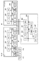
図1において、画像表示システム1は、本発明の画像送信装置として例示される複数のPC10と、画像出力装置として例示されるプロジェクタ20と、印刷装置として例示されるプリンタ40を備える。PC10とプロジェクタ20とプリンタ40とはLANなどの通信回線30を介して通信可能に接続されている。
In FIG. 1, an
PC10は、モニタに表示されている画像データをキャプチャし、通信回線30を介してプロジェクタ20やプリンタ40に送信する。プロジェクタ20は、PC10から受信した画像データを受信して、プロジェクタ20の画面に投影できる形式に変換して表示する。このとき、マウスなどの操作部10aによってPC10におけるウィンドウシステム上のポインタが操作されるが、ポインタの表示位置データは、画像データとは別にプロジェクタ20に送信される。なお、ここでいうウィンドウシステムとは、例えばマイクロソフト社のオペレーティングシステム(以下、OS)であるWindows(登録商標)によって実現される、Graphical User Interface(GUI)のことである。GUIにより、複数のタスクに固有の領域を、割当てて画面出力を多重化することが可能になる。プリンタ40は、PC10あるいはプロジェクタ20から受信した印刷ジョブに応じて印刷処理を実行する。
The PC 10 captures the image data displayed on the monitor and transmits it to the
また、画像表示システム1は、PC10と同等の機能を持つ複数のPC11,12が通信回線30を介してPC10と接続されている。
In the
プロジェクタ20は、PC10から受信した画像データを投影画面15に投影する際に、PC10の画面データを投影エリア16に、PC11の画面データを投影エリア17に、PC12の画面データを投影エリア18にそれぞれ表示する。また、他のPCから通信回線30を介して画面データを受信していない投影エリア19には、PC12のセカンダリモニタ112の画面データが表示されている。
When projecting the image data received from the PC 10 onto the
また、プロジェクタ20のみ図示しているが、通信回線30にはプロジェクタ20と同等の他のプロジェクタが複数接続可能であり、PC10は適宜画面データを投影する送信先のプロジェクタを選択可能である。
Although only the
<PC、プロジェクタ、及びプリンタのブロック構成>図2を参照して、PC10〜12とプロジェクタ20とプリンタ40の各ブロック構成について説明する。
<Block Configurations of PC, Projector, and Printer> The block configurations of the
図2において、PC10〜12は、CPU101、CPU101の処理手順を記述した制御プログラムを記憶するためのROM102、ワークメモリとして一時的に制御プログラムやデータを格納するRAM103を有する。また、PC10〜12は、アプリケーションやOSなどの各プログラムとデータを格納するためのハードディスクドライブ(HDD)104を備える。更に、PC10〜12は、通信回線30を介してプロジェクタ20や他のプロジェクタ、サーバなどと通信するための通信IF(インタフェース)106を備える。更にまた、PC10は、キーボードやポインティングデバイス(マウスなど)を介して入力されるユーザ操作を受け付けるユーザIF107を備える。
2, the
また、PC10〜12は、PC10〜12のモニタ画面に表示する画像データを記憶するVRAM108、画像処理部109、表示制御部110、液晶パネルなどの表示デバイスからなるモニタ111,112、これら各要素を接続する内部バス113を備える。なお、画像処理部109は、複数のモニタ111,112が接続されている場合には、モニタごとに表示対象の画像データを信号処理し、表示信号を生成する。なお、モニタは2台に限らず、3台以上であってもよい。
The
プロジェクタ20は、CPU201、CPU201の処理手順を記述した制御プログラムを記憶するためのROM202、ワークメモリとして一時的に制御プログラムやデータを格納するRAM203を備える。また、プロジェクタ20は、PC10〜12との通信可能に接続するための通信IF205、各種の操作ボタンや操作リモコンなどを介して入力されるユーザ操作を受け付けるユーザIF206を備える。更にまた、プロジェクタ20は、画像データを投影部208に出力するための投影制御部207、液晶パネル及びその駆動部、レンズ及びその駆動系、並びに光源からなる投影部208、これら各要素を接続する内部バス209を備える。なお、他のプロジェクタも同様の構成を有する。
The
プリンタ40は、CPU401、CPU401の処理手順を記述した制御プログラムを記憶するためのROM402、CPU401のメインメモリ、一時的に制御プログラムや印刷データを格納するワークエリア、印刷設定情報や制御パラメータ等を格納するNVRAM等に用いられるRAM403を有する。また、プリンタ40は、通信回線30を介してPC10〜12やプロジェクタ20や他のプロジェクタ、サーバなどと通信するための通信IF(インタフェース)404を備える。更に、プリンタ40は、ボタンやタッチパネルを介して入力されるユーザ操作を受け付けると共に、LEDランプ等を備える操作パネル405を備える。更にまた、プリンタ40は、印刷部(プリンタエンジン)407へ印刷データを出力する印刷部IF406と、メモリカードやHDD等の外部メモリ408を備える。上述した各要素は内部バス409を介して接続されている。
The
CPU401は、ROM402や外部メモリ408に記憶された制御プログラム等に基づいて内部バス409に接続される各要素とのアクセスを総括的に制御する。また、CPU401は、印刷部IF406を介して印刷部407に印刷データを出力する。更に、ROM402には、上記印刷データを生成する際に使用するフォントデータ等が格納されており、外部メモリ408が未接続の場合には、印刷処理を行う際の制御パラメータ等も記憶される。CPU401は、通信IF404を介して、PC10〜12やプロジェクタ20との通信が可能である。
The
<PC側での処理>次に、図3を参照して、PC10〜12による処理について説明する。なお、図3に示す処理は、PC10〜12においてプロジェクタ制御用のアプリケーション起動時に、HDD104に格納されているアプリケーションプログラムを、CPU101がRAM103に展開することで実行される。
<Processing on PC Side> Next, processing by the
図3(a)において、CPU101は、PC10〜12が多画面表示モードに設定されているか判定する(S101)。ここで、多画面表示モードとは、例えば、PC10〜12に複数のモニタ111,112が接続されており、各モニタごとに設定された画像を表示するモード、若しくはPC10〜12のモニタに表示された画像を複数の画像に分離して表示するモードである。ここでは、例えば、PC10〜12のWindows OSにおける画面のプロパティ設定におけるディスプレイの設定情報を取得することで複数のモニタの画面のレイアウト設定が判定できる。
In FIG. 3A, the
ここで、図5を参照して、多画面表示モードにおけるレイアウト設定について、PC10に接続されたプライマリモニタ111とセカンダリモニタ112のそれぞれに画像を表示している場合を例に説明する。
Here, with reference to FIG. 5, the layout setting in the multi-screen display mode will be described by taking an example in which images are displayed on each of the
図5(a)は同一サイズの2つのモニタ画面を左右に表示する場合のレイアウト設定を例示し、PC10に表示されたレイアウト設定画面500の中にプライマリモニタ501とセカンダリモニタ502が左右に並べて表示される。
FIG. 5A illustrates the layout setting when two monitor screens of the same size are displayed on the left and right, and the
図5(b)は同一サイズの2つのモニタ画面を上下にずらして左右に表示する場合のレイアウト設定を例示している。図5(b)では、PC10に表示されたレイアウト設定画面500の中にプライマリモニタ501とセカンダリモニタ502が左右に表示されるが、縦方向のY軸座標は異なる座標となる。
FIG. 5B illustrates a layout setting when two monitor screens of the same size are shifted up and down and displayed left and right. In FIG. 5B, the
図5(c)はサイズが異なる2つのモニタ画面を左右に表示する場合のレイアウト設定を例示し、レイアウト設定画面500の中に異なるサイズのプライマリモニタ503とセカンダリモニタ504が左右に並べて表示される。
FIG. 5C illustrates a layout setting when two monitor screens having different sizes are displayed on the left and right, and the
図5(d)はアスペクト比が異なる2つのモニタ画面を左右に表示する場合のレイアウト設定を例示し、レイアウト設定画面500の中に異なるアスペクト比のプライマリモニタ505とセカンダリモニタ506が左右に並べて表示される。
FIG. 5D illustrates a layout setting when two monitor screens having different aspect ratios are displayed on the left and right. A
図5(e)は同一サイズの4つのモニタ画面を上下左右に表示する場合のレイアウト設定を例示し、レイアウト設定画面500の中に同一アスペクト比の第1〜第4モニタ507〜510が上下左右に表示される。
FIG. 5E illustrates layout settings when four monitor screens of the same size are displayed in the vertical and horizontal directions. First to
なお、図5(a)〜(e)で例示したレイアウト設定以外にも様々なレイアウトが可能である。 Various layouts other than the layout settings exemplified in FIGS. 5A to 5E are possible.
図3の説明に戻り、ステップS101で多画面表示モードに設定されている場合には、CPU101は、PC10〜12からレイアウト設定情報を取得する(S102)。
Returning to the description of FIG. 3, if the multi-screen display mode is set in step S101, the
次に、CPU101は、例えば図5に示したレイアウト設定画面にて設定され、プロジェクタ20へ送信する対象となる画面データ(以下、送信画像データ)が複数存在するか判定する(S103)。ここで、送信画像データの設定はユーザがPC10〜12のモニタに表示されるアプリケーション画面を操作することにより行う。
Next, the
ステップS103で、送信画像データが複数存在する場合には、CPU101は、各画像データの送信先をユーザIF107を介して入力されたユーザ操作に従って決定する(S104)。
When there are a plurality of pieces of transmission image data in step S103, the
ステップS105では、CPU101は、送信画像データの送信先のプロジェクタとの通信接続を確立するため、通信IF106を介して接続要求を発行する。ここで発行される接続要求は、TCP/IPなどの通信プロトコル上に独自のパケット情報を付加して送信する。
In step S <b> 105, the
なお、ステップS101にて単一画面表示モードに設定されている場合又はステップS103にてプロジェクタへの送信画像データが複数存在しない場合には、ステップS105に移行する。ここで、単一画面表示モードは、例えば、PC10のセカンダリモニタ112が接続されておらず、PC10のプライマリモニタ111の画面データのみを表示するモードである。
If the single screen display mode is set in step S101, or if there are not a plurality of image data to be transmitted to the projector in step S103, the process proceeds to step S105. Here, the single screen display mode is a mode in which, for example, the
ステップS106では、CPU101は、接続要求先のプロジェクタから接続要求に対する返信を受信し、接続可能でれば接続を確立してステップS107に移行し、接続不可であれば本処理を終了する。
In step S106, the
ステップS107では、CPU101は、送信先のプロジェクタの投影部208の画面レイアウトを設定するため、各PCで設定された図5に示すレイアウト設定情報と画像情報とを通信IF106を介して送信先のプロジェクタへ送信する(S107)。ここで、画像情報は、画像の数と、各画像の解像度やアスペクト比(画面サイズ)、近接するレイアウトか否か、画面レイアウトにおける各画像の表示エリア、各画像の異同や相関などを示す情報を含む。
In step S <b> 107, the
次に、図3(b)を参照して、PC10のモニタ画面に表示されている画像データを通信回線30を介してプロジェクタ20へ送信する処理について説明する。
Next, processing for transmitting image data displayed on the monitor screen of the
図3(b)において、CPU101は、表示制御部110によってモニタに出力されている画像の座標を指定して、当該画像が格納されているVRAM108から画像データを取得する(S111)。複数のモニタに画像が表示されている場合には、各モニタに表示されている画像データの中で、ステップS104にて決定された各送信画像データの座標を指定してVRAM108から画像データを取得する(画像取得処理)。
In FIG. 3B, the
ステップS111にてキャプチャした各送信画像データは通信IF106を介して送信先のプロジェクタへ送信される(S112)。ここで、送信画像データが複数存在する場合には、図3(a)のステップS104にて設定された各送信先のプロジェクタに対象となる画像データを送信する(S112)。なお、複数の画像データを同一のプロジェクタに送信することも可能である。 Each transmission image data captured in step S111 is transmitted to the destination projector via the communication IF 106 (S112). Here, when there are a plurality of transmission image data, the target image data is transmitted to each destination projector set in step S104 of FIG. 3A (S112). It is also possible to transmit a plurality of image data to the same projector.
各画像データの送信が完了した後、CPU101は、プログラムの終了指示がユーザIF107を介して入力された場合には処理を終了し、終了指示が入力されていない場合にはステップS114に移行する(S113)。
After the transmission of each image data is completed, the
ステップS114では、CPU101は、表示制御部110から出力する画像データに更新があるのを待ち、更新があった場合にはステップS111に戻り、モニタに出力されている画像データをVRAM108から取得する。
In step S114, the
以上の処理により、PC10〜12が複数のモニタに表示している画像データを通信回線30を介して送信先のプロジェクタに送信することが可能となる。
With the above processing, the image data displayed on the plurality of monitors by the
<プロジェクタ側での処理>次に、図4を参照して、プロジェクタ20による処理について説明する。なお、図4に示す処理は、プロジェクタ20の電源投入時に、ROM202に格納されているファームウェアプログラムを、CPU201がRAM203に展開することで実行される。
<Processing at Projector Side> Next, processing by the
図4(a)において、CPU201は、通信回線30に接続されたPC10〜12のいずれかから接続要求を通信IF205を介して受信し(S201)、接続要求を受信した後、接続可能な状況であるかを判定する(S202)。
In FIG. 4A, the
ステップS202で接続可能な状況ならば、CPU201は、接続要求を送信したPCに対して接続要求を受け付けたことを通信IF205を介して通知する(S203)。接続が不可能な状況ならば、接続要求を送信したPCに対して接続を拒否することを通信IF205を介して通知して、本処理を終了する(S204)。
If the connection is possible in step S202, the
次に、CPU201は、ステップS203にて接続を確立したPC(ここでは、PC10とする)からプロジェクタ20のレイアウト設定情報と画像情報とを通信IF205を介して受信する(S205)。
Next, the
図4(b)はプロジェクタ20が、PC10から受信する複数の画像データを表示するためのレイアウトを決定する処理を示している。
FIG. 4B shows a process in which the
図4(b)において、CPU201は、プロジェクタ20側でユーザにより予め設定されている既存のレイアウト設定を、PC10から受信したレイアウトに自動的に変更できる変更許可設定になっているか判定する(S211)。変更許可設定になっている場合にはステップS212に移行し、変更不可設定であれば、図4(c)でプロジェクタ20側で設定された画面レイアウトに従ってPC10から受信した画像データを投影する。
4B, the
ステップS212では、CPU201は、接続を確立した同一機器であるPC10から複数の画像データを受信するか否かを判定する。ここでは、ステップS205で受信した画像情報から判定する。ステップS212で複数の画像データを受信する場合にはステップS213に移行し、複数の画像データを受信しない場合にはステップS220に移行する。
In step S212, the
ステップS213では、CPU201は、受信する複数の画像データが、図5(a)や図5(e)のように所定の間隔をもって近接する画面レイアウトか否かを判定する(レイアウト判定処理)。ステップS213での判定の結果、近接していない場合にはステップS220に移行し、近接している場合にはステップS214に移行する。
In step S213, the
ステップS214では、CPU201は、受信する複数の画像データが異なる画像データであるか否かを判定し(画像判定処理)、同じ画像データならば本処理を終了し、図4(c)の画像表示処理に移行し、異なる画像であればステップS215に移行する。
In step S214, the
ステップS215では、CPU201は、複数の画像データの解像度が同一か否かを判定し(サイズ判定処理及び解像度判定処理)、解像度が同一ならばステップS216に移行し、同一でないならばステップS217に移行する。
In step S215, the
ステップS216では、CPU201は、複数の画像データの画面アスペクト比が同一か否かを判定し(サイズ判定処理及びアスペクト比判定処理)、アスペクト比が同一ならばステップS219に移行し、同一でないならばステップS217に移行する。
In step S216, the
ステップS217では、CPU201は、プロジェクタ20側で予めユーザにより設定された既存の設定が、多画面表示の際に各画像を均等サイズ、同一アスペクト比で表示する設定となっているか判定する。均等サイズ、同一アスペクト比で表示する設定ならばステップS218に移行し、そうでなければステップS220に移行する。
In step S217, the
ステップS218では、CPU201は、複数の画像データの解像度及び/又はアスペクト比を、複数の画像データの中から選択された代表的な画像データの解像度及び/又はアスペクト比に合わせてレターボックス形式でリサイズする。ここでリサイズ処理は、ユーザにより予め設定された値に従ってもよいし、最も高い解像度とアスペクト比4:3に合わせるなど予め決められたルールに従ってもよい。
In step S218, the
ステップS219では、CPU201は、ユーザにより予め設定された画面レイアウト情報をRAM203から読み出し、複数の画像データを結合した画面レイアウト(第1のレイアウト)に変更する。
In step S219, the
ステップS220では、CPU201は、ユーザにより予め設定された画面レイアウト情報をRAM203から読み出し、複数の画像データを識別可能に分離した画面レイアウト(第2のレイアウト)に変更する。
In step S220, the
なお、ステップS219及びS220でのレイアウト設定を変更する際に、レイアウト変更を実行するか否かを、送信元のPC(ユーザ)に問い合わせる画面を表示し、ユーザの確認をとってからレイアウト変更を実行してもよい。また、ステップS219における表示レイアウトと、ステップS220における表示レイアウトを比較すると、複数の画像データ同士の配置位置が異なる。すなわち、ステップS219における表示レイアウトの方がステップS220における表示レイアウトに比べて、複数の画像データ同士の配置位置が近い距離である。または、ステップS220における表示レイアウトでは、複数の画像データ同士を分離するための枠線等の画像を表示するが、S219における表示レイアウトにおいては、枠線等の画像を表示しない。 When changing the layout setting in steps S219 and S220, a screen for inquiring to the transmission source PC (user) whether or not to execute the layout change is displayed, and the layout change is performed after confirmation from the user. May be executed. Also, a display layout in step S219, a comparison of the display layout in step S220, the arrangement position between the plurality of image data are different. That is, the display layout in step S219 is closer to the arrangement position of the plurality of image data than the display layout in step S220. Alternatively, in the display layout in step S220, an image such as a frame line for separating a plurality of image data is displayed. However, in the display layout in S219, an image such as a frame line is not displayed.
ここで、図6を参照して、ステップS219及びS220におけるレイアウト変更処理の具体例について説明する。 Here, a specific example of the layout change process in steps S219 and S220 will be described with reference to FIG.
図6(a)に複数の画像データの画像間距離を変更した場合の画面レイアウトを例示している。ステップS219では投影画面600にはプライマリモニタ111(又はPC11)の画像602とセカンダリモニタ112(又はPC12)の画像603が左右に結合して表示される。一方、ステップS220では投影画面601にはプライマリモニタ111(又はPC11)の画像604とセカンダリモニタ112(又はPC12)の画像605が識別可能に分離して表示される。本実施形態では、ステップS219における表示レイアウトは、投影画像602と603とを結合して表示している。しかし、結合していなくとも、ステップS220に対応する表示レイアウトよりも、投影画像同士の配置される位置が近ければよい。たとえば、ステップS220においては、投影画像は、10画素分横に離間して表示しているとすると、ステップS219においては、10画素よりも少ない画素数離間していれば良い。すなわち、ステップS219においては、9画素から0画素離間していれば良い。すなわち、ステップS219における表示レイアウトの方がステップS220における表示レイアウトに比べて、複数の画像データ同士の配置位置が近い距離である。
FIG. 6A illustrates a screen layout when the distance between images of a plurality of image data is changed. In step S219, the
図6(b)に各画像に枠を表示する場合の画面レイアウトを例示している。ステップS219では投影画面600にはプライマリモニタ111(又はPC11)の画像602とセカンダリモニタ112(又はPC12)の画像603を左右に結合させ、かつ画像602と画像603の画像全体の外縁を枠606により囲って表示する。一方ステップS220では投影画面601にはプライマリモニタ111(又はPC11)の画像604の外縁を枠607、セカンダリモニタ112(又はPC12)の画像605の外縁を枠608で囲うことで各々の画像を識別可能に分離させる(枠表示処理)。
FIG. 6B illustrates a screen layout when a frame is displayed on each image. In
図6(c)に複数の画像の離間距離を変更した場合の画面レイアウトを例示している。ステップS219では投影画面600にはプライマリモニタ111(又はPC11)の画像602とセカンダリモニタ112(又はPC12)の画像603が左右に結合して表示される。一方、ステップS220では投影画面601にはプライマリモニタ111(又はPC11)の画像604とセカンダリモニタ112(又はPC12)の画像605との間に区切り線609で区切ることで各々の画像を識別可能に分離させる(線表示処理)。
FIG. 6C illustrates a screen layout when the separation distance of a plurality of images is changed. In step S219, the
図6(d)に複数の画像の離間距離を大きく変更した場合の画面レイアウトを例示している。ステップS219では投影画面600にはプライマリモニタ111の画像602とセカンダリモニタ112の画像603を左右に結合して表示する。同時に、画像602の近傍には画像602を表示しているプライマリモニタ111の名前610、画像603の近傍には画像603を表示しているセカンダリモニタ112の名前611がそれぞれ表示される(識別情報表示処理)。
FIG. 6D illustrates a screen layout when the separation distance between a plurality of images is greatly changed. In step S219, the
一方、ステップS220では投影画面601にはPC11の画像604とPC12の画像605を結合する。そして、画像604の近傍に画像604の送信元となるPC11の識別情報612、画像605の近傍に画像605の送信元となるPC12の識別情報613を表示する(識別情報表示処理)。
On the other hand, in step S220, the
図4(c)はプロジェクタがPCから画像データを受信して表示するまでの処理を示している。 FIG. 4C shows processing until the projector receives image data from the PC and displays it.
図4(c)において、PCとの接続が確立されると本プログラムが起動し、通信IF205を介して通信回線30上に存在するPCから送信される画像データの受信待ち状態となる(S231)。
In FIG. 4 (c), when the connection with the PC is established, this program is activated and enters a state of waiting for receiving image data transmitted from the PC existing on the
ステップS232では、CPU201は、PC側から受信したレイアウト設定情報又はステップS219、S220で設定された画面レイアウトに従い、受信した画像データの投影画面における表示エリアを決定する。
In step S232, the
ステップS233では、CPU201は、決定された表示エリアごとに投影制御部207を介して画像データを投影部208に投影する。
In step S233, the
ステップS234では、CPU201は、PCとの接続が切断されたか否か判定し、切断された場合には本処理を終了し、切断されていない場合にはステップS231に戻り、画像の受信待ち状態となる。
In step S234, the
以上の処理によれば、プロジェクタが同一のPCから送信される複数の画像データを多画面表示する際に、各画像データの関連性に応じて表示形態を変更する。例えば、PC側で所定の間隔をもって近接する画像であれば左右に結合して表示し、それ以外ならば識別可能に分離して表示するので、画像の視認性が向上する。 According to the above process, when the projector displays a plurality of image data transmitted from the same PC on a multi-screen, the display form is changed according to the relevance of each image data. For example, if the images are close to each other with a predetermined interval on the PC side, they are combined and displayed on the left and right sides, otherwise they are displayed separately so as to be identifiable, thereby improving the visibility of the images.
[実施形態2]次に、実施形態2として、PC側で複数の送信画像データを結合して送信する処理について説明する。なお、本実施形態を実現する画像表示システムのブロック構成は、前述した実施形態1と同様であるため、説明を省略する。
[Embodiment 2] Next, as
実施形態1ではPCから受信した画像データのレイアウトをプロジェクタ側で変更していたのに対して、本実施形態ではPC側でプロジェクタでの画面レイアウトを変更する。 In the first embodiment, the layout of the image data received from the PC is changed on the projector side. In the present embodiment, the screen layout on the projector is changed on the PC side.
図7を参照して、実施形態2のPC10〜12の処理について説明する。なお、本処理において、プロジェクタとの通信接続を確立する処理については図3(a)で説明した通りである。また、図7に示す処理は、PC10〜12においてプロジェクタ制御用のアプリケーション起動時に、HDD104に格納されているアプリケーションプログラムを、CPU101がRAM103に展開することで実行される。
With reference to FIG. 7, the process of PC10-12 of
図7において、CPU101は、画像処理部109により表示制御部110を介して複数のモニタ111,112に表示されている画像データをVRAM108から取得する(S301)。
In FIG. 7, the
ステップS302では、CPU101は、複数の画像データの送信先が同一のプロジェクタであるか否かを判定する。送信先が同一の場合にはステップS303に移行し、異なる場合にはステップS308に移行する。
In step S302, the
ステップS303では、CPU101は、送信対象の複数の画像データが図5(a)や図5(e)のように所定の間隔をもって近接する画面レイアウトか否かを判定する。近接している場合にはステップS303に移行し、近接していない場合にはステップS308に移行する。本実施形態では、図5(a)、図5(e)のように、所定の間隔を持って近接する画像レイアウトである場合には、画像データを取り込む際に、複数の画像を1つの画像データに結合した画像を生成するのである。
In step S303, the
さらに、ステップS304では、CPU101は、送信対象の複数の画像データの画面アスペクト比が同一であるか否かを判定する(S304)。アスペクト比が同一ならばステップS305に移行し、同一でないならばステップS308に移行する。
Further, in step S304, the
ステップS305では、CPU101は、送信対象の複数の画像データの解像度が同一であるか否かを判定する。解像度が同一ならばステップS306に移行し、同一でないならばステップS308に移行する。
In step S305, the
ステップS306では、CPU101は、送信対象の複数の画像データが異なっているか否かを判定し、異なっているならばステップS307に移行し、同じならばステップS308に移行する。
In step S306, the
ステップS307では、CPU101は、所定の間隔をもって近接する画像データを結合する。すなわち、ステップS307においては、CPU101は、所定の間隔を持って近接する複数の画像データをひとつの画像データとして結合した状態で画像を取り込むのである。
In step S307, the
ステップS308では、CPU101は、送信先のプロジェクタの画面レイアウトを設定する。ここで、ステップS307で結合した画像データを表示できるようなレイアウトに設定するためのレイアウト設定情報を送信先のプロジェクタへ送信する。
In step S308, the
ステップS309では、CPU101は、送信対象の各画像データを送信先のプロジェクタへ送信する。
In step S309, the
各画像データの送信が完了した後、CPU101は、プログラムの終了指示がユーザIF107を介して入力された場合には処理を終了し、終了指示が入力されていない場合にはステップS311に移行する(S310)。
After the transmission of each image data is completed, the
ステップS311では、CPU101は、表示制御部110にて出力する画像データに更新があるのを待ち、更新があった場合にはステップS301に戻り、各モニタ111,112に出力されている画像データをVRAM108から取得する。
In step S311, the
プロジェクタ20側での画像表示処理については、図4(b)の処理を除き、図4(a)及び図4(c)と同一である。
The image display process on the
[実施形態3]次に、実施形態3として、PC側で全てのモニタに表示されている全ての画像データを取得し、取得した画像データをモニタごとに分離又は送信先ごとに結合して送信する処理について説明する。なお、本実施形態を実現する画像表示システムのブロック構成は、前述した実施形態1と同様であるため、説明を省略する。なお、本実施形態では、PC10には2台のモニタ111,112が接続されている例で説明しているが、3台以上のモニタが接続されている場合であってもよい。
[Third Embodiment] Next, as a third embodiment, all image data displayed on all monitors on the PC side is acquired, and the acquired image data is separated for each monitor or combined for each transmission destination and transmitted. Processing to be performed will be described. Note that the block configuration of the image display system that realizes the present embodiment is the same as that of the first embodiment, and a description thereof will be omitted. In the present embodiment, an example in which two
図8を参照して、実施形態2のPCでの処理について説明する。なお、本処理において、プロジェクタとの通信接続を確立する処理については図3(a)で説明した通りである。また、図8に示す処理は、PC10においてプロジェクタ制御用のアプリケーション起動時に、HDD104に格納されているアプリケーションプログラムを、CPU101がRAM103に展開することで実行される。
With reference to FIG. 8, the processing in the PC according to the second embodiment will be described. In this process, the process for establishing a communication connection with the projector is as described with reference to FIG. 8 is executed when the
図8において、CPU101は、画像処理部109により表示制御部110を介して全てのPC10のモニタに表示されている全ての画像データをVRAM108から取得する(S401)。
In FIG. 8, the
ステップS402では、CPU101は、ステップS401でキャプチャした全ての画像データのうち、送信先が同一の画像データが複数存在するか判定する。送信先が同一の画像データが複数存在する場合にはステップS403に移行し、送信先が異なっている場合又は送信先が同一の画像データが単一の場合にはステップS407に移行する。
In step S402, the
ステップS403では、CPU101は、送信先が同一である複数の画像データが図5(a)、(e)のように所定の間隔をもって近接する画面レイアウトか否かを判定する。そして、近接している場合にはステップS403に移行し、近接していない場合にはステップS407に移行する。
In step S403, the
ステップS404では、CPU101は、送信先が同一で互いに近接する画面レイアウトの複数の画像データの画面アスペクト比が同一であるか否かを判定し、同一ならばステップS405に移行し、同一でないならばステップS407に移行する。
In step S404, the
ステップS405では、CPU101は、送信先が同一で互いに近接する画面レイアウトの複数の画像データの解像度が同一であるかを判別し、同一ならばステップS406に移行し、同一でないならばステップS407に移行する。
In step S405, the
ステップS406では、CPU101は、送信先が同一で互いに近接する画面レイアウトの複数の画像データが異なっているか否かを判定し、同一である場合にはステップS407に移行し、異なっている場合にはステップS408に移行する。
In step S406, the
ステップS407では、CPU101は、モニタごとに画像データを識別可能に分離した1つの画像を生成し、RAM103に格納し、ステップS409に移行する。
In step S407, the
ステップS408では、CPU101は、送信先が同一で互いに近接する画面レイアウトの複数の画像データについて、送信先ごとに複数の画像データを結合した1つの画像を生成する。そして、結合した画像データをRAM103に格納し、ステップS409に移行する。
In step S <b> 408, the
ステップS409では、ステップS407、S408で分離又は結合された画像データを表示できるようなレイアウト設定情報を、送信先のプロジェクタへ送信する。 In step S409, layout setting information that can display the image data separated or combined in steps S407 and S408 is transmitted to the destination projector.
その後、CPU101は、各画像データを送信先のプロジェクタへ送信し(S410)、各画像データの送信が完了した後、プログラムの終了指示があった場合には処理を終了する(S411)。また、終了指示が入力されていない場合にはステップS412に移行し、表示制御部110にて出力する画像データに更新があるのを待ち、更新があった場合にはステップS401に戻り、再度モニタから画像データをVRAM108から取得する。
After that, the
プロジェクタ20側での画像表示処理については、図4(b)の処理を除き、図4(a)及び図4(c)と同一である。
The image display process on the
[実施形態4]次に、実施形態4として、プロジェクタ20が、複数のPCから画像データを受信した場合のレイアウト変更処理について説明する。本実施形態では、複数のPCから画像データを受信した場合であっても、所定の条件を満たせば、図6の投影画面600のように各画像を結合するようにプロジェクタ側で画面レイアウトを変更する。なお、図9に示す処理は、図4(b)に対応し、プロジェクタ20の電源投入時に、ROM202に格納されているファームウェアプログラムを、CPU201がRAM203に展開することで実行される。
[Fourth Embodiment] Next, as a fourth embodiment, a layout changing process when the
本実施形態を実現する画像表示システムのブロック構成は、前述した実施形態1と同様であるため、説明を省略する。また、PC10〜12側での処理については、図3と同様であり、プロジェクタ20側での画像表示処理については図4(b)の処理を除き、図4(a)及び図4(c)と同一である。
The block configuration of the image display system that realizes the present embodiment is the same as that of the first embodiment described above, and a description thereof will be omitted. The processing on the PC 10-12 side is the same as that in FIG. 3, and the image display processing on the
図9において、CPU201は、プロジェクタ20側での既存のレイアウト設定を、PC10から受信したレイアウトに自動的に変更してもよい変更許可設定になっているか否か判定する(S501)。変更許可設定になっている場合にはステップS502に移行し、変更不可設定であれば、図4(c)でプロジェクタ20側で設定された画面レイアウトに従ってPCから受信した画像データを投影する。
In FIG. 9, the
ステップS502では、CPU201は、プロジェクタ20が接続を確立した複数のPCから画像データを受信するか否かを判定する。ここでは、図4(a)のステップS205で受信した画像情報から判定する。
In step S502, the
ステップS502で複数の画像データを受信する場合にはステップS503に移行し、複数の画像データを受信しない場合にはステップS506に移行する。 If a plurality of image data is received in step S502, the process proceeds to step S503. If a plurality of image data is not received, the process proceeds to step S506.
ステップS503では、CPU201は、複数のPCから受信する各画像データの解像度が同一か否かを判定し、各画像データの解像度が同一ならばステップS504に移行し、同一ではないならばステップS506に移行する。
In step S503, the
次に、ステップS504では、CPU201は、複数のPCから受信する各画像データの画面アスペクト比が同一か否かを判定し、アスペクト比が同一ならばステップS505に移行し、同一でないならばステップS506に移行する。
Next, in step S504, the
ステップS505では、CPU201は、ユーザにより予め設定された画面レイアウト情報をRAM203から読み出し、複数の画像データを結合した画面レイアウトに変更する。
In step S505, the
ステップS506では、CPU201は、ユーザにより予め設定された画面レイアウト情報をRAM203から読み出し、複数の画像データを識別可能に分離した画面レイアウトに変更する。
In step S506, the
プロジェクタ20側での画像表示処理については、図4(b)の処理を除き、図4(a)及び図4(c)と同一である。
The image display process on the
以上説明したように、上記各実施形態によれば、プロジェクタの投影画面に複数の画像を投影する際に、例えば同じPCの複数の表示部で表示されている画像のように、関連性の高い画像については結合したレイアウトとする。一方、例えば個々のPCごとに表示されている画像のように、関連性の低い画像については枠や線などで識別可能に分離したレイアウトとする。このように画像間の関連性に応じて表示形態を変更することで、視認性を向上することができる。 As described above, according to each of the embodiments described above, when a plurality of images are projected on the projection screen of the projector, for example, images that are displayed on a plurality of display units of the same PC are highly relevant. The image has a combined layout. On the other hand, for example, an image having low relevance, such as an image displayed for each PC, has a layout separated so as to be identifiable by a frame or a line. Thus, visibility can be improved by changing a display form according to the relevance between images.
[実施形態5]次に、実施形態5として、プロジェクタ20により多画面表示されている画像同士の関連性に応じて、プリンタ40による印刷方式を変更する処理について説明する。本実施形態では、プロジェクタ20が、多画面表示モードであるか、多画面表示された各画像データが同一のPCから受信したものであるか、異なるPCから受信したものであるかに応じて、全ての画像を印刷媒体である1枚のシートに印刷するか、別々のシートに印刷するかを決定する。
[Embodiment 5] Next, as Embodiment 5, processing for changing the printing method by the
なお、本実施形態を実現する画像表示システムのブロック構成は、前述した実施形態1と同様であるため、説明を省略する。 Note that the block configuration of the image display system that realizes the present embodiment is the same as that of the first embodiment, and a description thereof will be omitted.
図10は、PC10〜12側での処理を示しており、PCがプロジェクタと通信接続を確立するまでの処理は図3(a)と同様である。また、図10(a)のステップS601、S603〜S605は、図3(b)のステップS111〜S114と同様であるため、以下では異なる部分を中心に説明する。
FIG. 10 shows processing on the
図10(a)において、CPU101は、ステップS601にてキャプチャした各送信画像データをRAM103に格納する(S602)。ここで、RAM103に格納する画像データはリングバッファのように構成され、数フレームのデータを保持でき、画像データを識別するための識別情報(画像ID)が付加されている。
In FIG. 10A, the
ステップS603では、CPU101は、図3(b)のステップS112と同様に、キャプチャした各送信画像データを通信IF106を介して送信先のプロジェクタへ送信する(S603)。ここで、送信画像データが複数存在する場合には、図3(a)のステップS104にて設定された各送信先のプロジェクタに対象となる画像データと画像IDを送信する。なお、複数の画像データを同一のプロジェクタに送信することも可能である。
In step S603, the
各画像データの送信が完了した後、CPU101は、図3(b)のステップS113〜S114と同様に、プログラムの終了処理(S604でYES)、画像の更新処理(S605)を実行する。
After the transmission of each image data is completed, the
図10(b)は、プロジェクタ20からリサイズ処理前の元画像データの送信要求を受信した場合のPC側の処理を示している。
FIG. 10B shows processing on the PC side when a transmission request for original image data before resizing processing is received from the
図10(b)において、CPU101は、プロジェクタ20から元画像データの送信要求を受信した場合(S611でYES)、送信要求に付加されている画像IDと同一の画像データをRAM103から読み出して、プロジェクタ20へ送信する(S612)。なお、元画像データの送信要求は、TCP/IPなどの通信プロトコル上に独自のパケット情報を付加して送信する。ここでのパケットは、元画像データの送信要求であることを示すOperationコードと、要求している画像データを識別するための画像IDとで構成されるパケットとする。
In FIG. 10B, when the
画像データの送信が完了した後、CPU101は、図3(b)のステップS113と同様に、プログラムの終了処理を実行する。
After the transmission of the image data is completed, the
<プロジェクタ側での処理>次に、図11を参照して、プロジェクタ20による画像印刷処理について説明する。なお、図11に示す処理は、プロジェクタ20の電源投入時に、ROM202に格納されているファームウェアプログラムを、CPU201がRAM203に展開することで実行される。また、PCと通信接続を確立してから画像データを表示するまでの処理は図4(a)〜(c)と同様である。
<Processing at Projector Side> Next, an image printing process by the
図11において、CPU201は、ユーザがプロジェクタ20の操作ボタンや操作リモコンを操作することより、ユーザIF206を介して印刷指示を受信したか判定する(S701)。
In FIG. 11, the
ステップS701で印刷指示を受信したならば、CPU201は、PC10〜12が多画面表示モードに設定され、投影部208により複数の画像が複数の投影画面で多画面表示されているか判定する(S702)。
If a print instruction is received in step S701, the
ステップS702で多画面表示されていない場合には、CPU201は、投影画面に表示されている単一の画像を1枚のプリントシートに印刷する通常の印刷方式に応じた印刷プレビューを表示する(S704)。
If the multi-screen is not displayed in step S702, the
一方、ステップS702で多画面表示されている場合には、CPU201は、複数の画像データの送信元が同一のであるか判定する(S703)。
On the other hand, if multiple screens are displayed in step S702, the
ステップS703で送信元が同一である場合には、CPU201は、多画面表示されている複数の画像を1枚のプリントシートに印刷する第1の印刷方式に応じた印刷プレビューを表示する(S705)。ここで、印刷プレビューを表示する際には、現在投影部28に投影されている画像と同じ画像データをRAM203から読み出して表示する。
If the transmission sources are the same in step S703, the
一方、ステップS703で送信元が同一ではない場合には、CPU201は、多画面表示されている複数の画像を、別々のプリントシートに印刷する第2の印刷方式に応じた印刷プレビューを表示する(S706)。ここでも、印刷プレビューを表示する際には、現在投影部28に投影されている画像の矩形領域をRAM203から読み出して表示する。
On the other hand, if the transmission sources are not the same in step S703, the
なお、ステップS705、S706での処理を実現するためには、投影部28に投影されている間はRAM203に画像データを保持しておく必要がある。
In order to realize the processing in steps S705 and S706, it is necessary to store image data in the
ステップS704〜S706で印刷プレビューを表示した後、CPU201は、ユーザIF206を介してユーザにより印刷設定が変更されたか判定する(S707)。
After displaying the print preview in steps S704 to S706, the
ステップS707で印刷設定に変更がない場合には、CPU201は、ステップS709に進み、印刷設定に変更があった場合にはステップS708に進み、ユーザ操作に応じた印刷設定に変更した後、ステップS709に進む。
If the print setting is not changed in step S707, the
ステップS709では、CPU201は、ユーザIF206を介して印刷キャンセル操作を受け付けたか判定し、印刷キャンセルを受け付けた場合には、本処理を終了し、そうでなければステップS710に進む。
In step S709, the
ステップS710では、CPU201は、ユーザIF206を介して印刷実行操作を受け付けたか判定し、印刷実行を受け付けるまでは、ステップS707〜S709の処理を繰り返し、印刷実行を受け付けると、ステップS711に進む。
In step S710, the
ステップS711では、CPU201は、多画面表示されている複数の画像に、リサイズ済みの画像があるか判定し、リサイズ済みの画像があった場合には、ステップS712に進み、リサイズ済みの画像がない場合には、ステップS713に進む。
In step S711, the
ステップS712では、CPU201は、リサイズ済みの画像の送信元に対して、通信IF205を介して元画像データの送信要求を送信する。なお、元画像データの送信要求は、元画像データの送信要求であることを示すOperationコードと、要求している画像データを識別するための画像IDとで構成される。そして、CPU201は、元画像データの送信要求を受信したPCから、図10(b)に従って送信された元画像データを、通信IF205を介して受信する。
In step S712, the
ステップS713では、CPU201は、プリンタ40に対して印刷の実行を指示するための印刷ジョブを発行する。印刷ジョブには、ステップS704〜S706でプレビュー表示された印刷方式(印刷レイアウト)、用紙サイズ、カラーモード、印刷部数等の印刷設定情報が含まれる。なお、プリンタ40は、予め宛先として設定されてROM202に格納されたIPアドレスやプリンタ名等から判別されるが、それ以外に、接続機器検出用のプロトコルを用いて自動的に認識してもよい。
In step S713, the
ステップS713でプリンタ40に印刷ジョブを発行した後、CPU201は、印刷対象の画像データをプリンタ40へ送信する(S714)。なお、ステップS706で複数枚のプリントシートに印刷する第2の印刷方式の場合は印刷する画像データを順次送信する。
After issuing a print job to the
ステップS715では、CPU201は、通信IF205を介してプリンタ40から印刷完了通知を受信するまで待ち、印刷完了通知を受信すると、印刷完了画面を表示して処理を終了する(S716)。
In step S715, the
なお、図11のステップS704からS706では、印刷プレビューを表示する例を説明したが、印刷実行前の印刷プレビュー表示を省略しても良い。 In addition, although the example which displays a print preview was demonstrated in step S704 to S706 of FIG. 11, you may abbreviate | omit the print preview display before printing execution.
図13(a)は、図11のステップS705において、多画面表示された複数の画像を1枚のプリントシートに印刷する第1の印刷方式の場合の印刷プレビューの表示例を示している。画面1301は、ユーザが現在の印刷設定情報の確認を行うための、印刷部数、用紙サイズ、印刷方式、プリンタ名等の印刷設定情報の表示1302、印刷実行を指示するための印刷ボタン1303、印刷中止を指示するためのキャンセルボタン1304、印刷レイアウト1305から構成される。
FIG. 13A shows a display example of a print preview in the case of the first printing method in which a plurality of images displayed on multiple screens are printed on one print sheet in step S705 of FIG. A
図13(b)は、図11のステップS706において、多画面表示された複数の画像を、別々のプリントシートに印刷する第2の印刷方式の場合の印刷プレビューの表示例を示している。画面1310は、図13(a)と同様に、印刷設定情報の表示1302、印刷ボタン1303、キャンセルボタン1304、そして、プリントシートごとの画像の印刷レイアウト1306、1307から構成される。
FIG. 13B shows a display example of a print preview in the case of the second printing method in which a plurality of images displayed on multiple screens are printed on different print sheets in step S706 of FIG. As in FIG. 13A, the
<プリンタでの処理>次に、図12を参照して、プリンタ40による印刷処理について説明する。なお、図12に示す処理は、プリンタ40の電源投入時に、ROM402に格納されているファームウェアプログラムを、CPU401がRAM403に展開することで実行され、プロジェクタ20との通信接続は確立されているものとする。
<Processing by Printer> Next, the printing process by the
図12において、先ずCPU401は、操作パネル405を介してプログラムの終了指示を受けているか判定し(S801)、終了指示があれば処理を終了し、終了指示を受けていなければ、ステップS802に進む。
In FIG. 12, first, the
ステップS802では、CPU401は、通信IF404を介してプロジェクタ20から印刷ジョブを受信するまで待ち、印刷ジョブを受信すると、ステップS803に進む。
In step S802, the
ステップS803では、CPU401は、印刷ジョブ受信後にプロジェクタ20から送信される印刷対象の画像データと印刷設定情報を受信し、RAM403あるいは外部メモリ408に一時的に保持する。ここで、複数枚のプリントシートに印刷を行う第2の印刷方式の場合には、順次送信される画像データを受信して印刷処理を実行する。
In step S <b> 803, the
ステップS804では、CPU401は、RAM403あるいは外部メモリ408に一時的に保持された画像データと印刷設定情報を、印刷部IF406から印刷部407へ送り、印刷処理を実行する。
In step S804, the
ステップS804での印刷処理が終了したことを、印刷部IF406を介して確認すると、CPU401は、通信IF404を介してプロジェクタ20に印刷完了通知を送信し、ステップS801に戻る。
Upon confirming that the printing process in step S804 has been completed via the printing unit IF 406, the
以上説明したように、本実施形態によれば、投影部28に多画面表示された複数の画像を印刷する場合に、各画像が同一の送信元の場合には1枚のプリントシートに全ての画像を印刷し、異なる送信元の場合には、各画像を別々のプリントシートに印刷する。このように、多画面表示された複数の画像を印刷する場合に、画像同士の関連性に応じて印刷方式を変更することで、印刷結果の視認性を向上することができる。 As described above, according to the present embodiment, when printing a plurality of images displayed on the multi-screen on the projection unit 28, if each image is the same transmission source, all the images are printed on one print sheet. Images are printed, and for different senders, each image is printed on a separate print sheet. As described above, when printing a plurality of images displayed on multiple screens, the visibility of the print result can be improved by changing the printing method according to the relevance between the images.
[他の実施形態]本発明は、以下の処理を実行することによっても実現される。即ち、上記実施形態の機能を実現するソフトウェア(プログラム)をネットワーク又は各種記憶媒体を介してシステム或いは装置に供給し、そのシステム或いは装置のコンピュータ(又はCPUやMPUなど)がプログラムコードを読み出して実行する処理である。この場合、そのプログラム、及び該プログラムを記憶した記憶媒体は本発明を構成することになる。 [Other Embodiments] The present invention is also realized by executing the following processing. That is, software (program) that realizes the functions of the above-described embodiments is supplied to a system or apparatus via a network or various storage media, and a computer (or CPU, MPU, etc.) of the system or apparatus reads and executes the program code It is processing to do. In this case, the program and the storage medium storing the program constitute the present invention.
Claims (8)
前記受信手段により受信した複数の画像データを複数の表示エリアに表示する表示手段と、
印刷装置に対して、前記表示手段により表示されている画像データに対応する画像データを印刷するための情報を送信する送信手段と、
前記表示手段により表示されている複数の画像データが、同一の画像送信装置から送信された画像データであるのか、異なる画像送信装置から送信された画像データであるのかを判定する判定手段と、
前記判定手段による判定の結果に応じて、前記表示手段に表示されている複数の画像データを前記印刷装置により印刷する際の印刷方式を決定する決定手段と、を有し、
前記決定手段は、前記複数の画像データが同一の画像送信装置から受信したデータである場合には、当該複数の画像データを一つの印刷媒体に印刷する第1の印刷方式で印刷し、前記複数の画像データが異なる画像送信装置から受信したデータである場合には、当該複数の画像データを別々の印刷媒体に印刷する第2の印刷方式で印刷するように印刷方式を決定することを特徴とする画像出力装置。 Receiving means for receiving image data from a plurality of image transmitting devices;
Display means for displaying a plurality of image data received by the receiving means in a plurality of display areas;
Transmitting means for transmitting information for printing image data corresponding to the image data displayed by the display means to the printing apparatus;
Determining means for determining whether the plurality of image data displayed by the display means is image data transmitted from the same image transmitting apparatus or image data transmitted from different image transmitting apparatuses;
Wherein according to the result of determination by the determination means, have a, a determination unit configured to determine a printing method for printing by a plurality of image data displayed on the display means the printing apparatus,
When the plurality of pieces of image data are data received from the same image transmission device, the determination unit prints the plurality of pieces of image data using a first printing method for printing on a single print medium, When the image data is data received from different image transmission devices, the printing method is determined so as to be printed by the second printing method for printing the plurality of image data on different printing media. Image output device.
前記送信手段は、前記決定手段により決定された印刷方式に応じた印刷に関する設定情報を含む情報と、前記表示されている画像データ又は前記取得手段により取得した前記リサイズされた画像データに対応する画像データとを前記印刷装置へ送信することを特徴とする請求項1または2に記載の画像出力装置。 It is determined whether any of the plurality of image data displayed in the plurality of display areas is resized image data, and the image data determined to be resized is determined to be resized. Acquisition means for acquiring image data corresponding to the resized image data from an image transmission device that is a transmission source of the received image data,
The transmission means includes information including setting information related to printing according to the printing method determined by the determination means, and the displayed image data or an image corresponding to the resized image data acquired by the acquisition means the image output apparatus according to claim 1 or 2, characterized in that transmits the data to the printing device.
前記送信要求は、前記リサイズされた画像データに対応する画像データを識別するための情報を含むことを特徴とする請求項3に記載の画像出力装置。 The acquisition means transmits a transmission request for image data corresponding to the resized image data to a transmission source of the image data determined to be resized,
The image output apparatus according to claim 3 , wherein the transmission request includes information for identifying image data corresponding to the resized image data.
前記画像送信装置は、
表示部に表示されている画像データに対応する画像データを取得する画像取得手段と、
前記画像取得手段により取得された画像データを前記画像出力装置に送信する送信手段と、を有し、
前記画像出力装置は、
複数の画像送信装置から画像データを受信する受信手段と、
前記受信手段により受信した複数の画像データを複数の表示エリアに表示する表示手段と、
印刷装置に対して、前記表示手段により表示されている画像データに対応する画像データを印刷するための情報を送信する送信手段と、
前記表示手段により表示されている複数の画像データが、同一の画像送信装置から送信された画像データであるのか、異なる画像送信装置から送信された画像データであるのかを判定する判定手段と、
前記判定手段による判定の結果に応じて、前記表示手段に表示されている複数の画像データを前記印刷装置により印刷する際の印刷方式を決定する決定手段と、を有し、
前記決定手段は、前記複数の画像データが同一の画像送信装置から受信したデータである場合には、当該複数の画像データを一つの印刷媒体に印刷する第1の印刷方式で印刷し、前記複数の画像データが異なる画像送信装置から受信したデータである場合には、当該複数の画像データを別々の印刷媒体に印刷する第2の印刷方式で印刷するように印刷方式を決定することを特徴とするシステム。 A system comprising at least one image transmission device and an image output device,
The image transmission device includes:
Image acquisition means for acquiring image data corresponding to the image data displayed on the display unit;
Transmission means for transmitting the image data acquired by the image acquisition means to the image output device,
The image output device includes:
Receiving means for receiving image data from a plurality of image transmitting devices;
Display means for displaying a plurality of image data received by the receiving means in a plurality of display areas;
Transmitting means for transmitting information for printing image data corresponding to the image data displayed by the display means to the printing apparatus;
Determining means for determining whether the plurality of image data displayed by the display means is image data transmitted from the same image transmitting apparatus or image data transmitted from different image transmitting apparatuses;
Wherein according to the result of determination by the determination means, have a, a determination unit configured to determine a printing method for printing by a plurality of image data displayed on the display means the printing apparatus,
When the plurality of pieces of image data are data received from the same image transmission device, the determination unit prints the plurality of pieces of image data using a first printing method for printing on a single print medium, When the image data is data received from different image transmission devices, the printing method is determined so as to be printed by the second printing method for printing the plurality of image data on different printing media. System.
複数の画像送信装置から画像データを受信する受信工程と、
前記受信工程により受信した複数の画像データを複数の表示エリアに表示する表示工程と、
印刷装置に対して、前記表示エリアに表示されている画像データに対応する画像データを印刷するための情報を送信する送信工程と、
前記表示エリアに表示されている複数の画像データが、同一の画像送信装置から送信された画像データであるのか、異なる画像送信装置から送信された画像データであるのかを判定する判定工程と、
前記判定の結果に応じて、前記表示エリアに表示されている複数の画像データを前記印刷装置により印刷する際の印刷方式を決定する決定工程と、を有し、
前記決定工程では、前記複数の画像データが同一の画像送信装置から受信したデータである場合には、当該複数の画像データを一つの印刷媒体に印刷する第1の印刷方式で印刷し、前記複数の画像データが異なる画像送信装置から受信したデータである場合には、当該複数の画像データを別々の印刷媒体に印刷する第2の印刷方式で印刷するように印刷方式を決定することを特徴とする制御方法。 A control method for an image output device connected to an image transmission device,
A receiving step of receiving image data from a plurality of image transmitting devices;
A display step of displaying a plurality of image data received in the reception step in a plurality of display areas;
A transmission step of transmitting information for printing image data corresponding to the image data displayed in the display area to the printing apparatus;
A determination step of determining whether the plurality of image data displayed in the display area is image data transmitted from the same image transmission device or image data transmitted from different image transmission devices;
Wherein according to the result of determination, have a, a determination step of determining a printing method for printing by said plurality of image data displayed on the display area printing device,
In the determining step, when the plurality of pieces of image data are data received from the same image transmission apparatus, the plurality of pieces of image data are printed by a first printing method for printing on one print medium, and the plurality of pieces of image data are printed. When the image data is data received from different image transmission devices, the printing method is determined so as to be printed by the second printing method for printing the plurality of image data on different printing media. Control method to do.
Priority Applications (1)
| Application Number | Priority Date | Filing Date | Title |
|---|---|---|---|
| JP2013004049A JP6176928B2 (en) | 2013-01-11 | 2013-01-11 | Image output apparatus, control method therefor, system, program, and storage medium |
Applications Claiming Priority (1)
| Application Number | Priority Date | Filing Date | Title |
|---|---|---|---|
| JP2013004049A JP6176928B2 (en) | 2013-01-11 | 2013-01-11 | Image output apparatus, control method therefor, system, program, and storage medium |
Publications (2)
| Publication Number | Publication Date |
|---|---|
| JP2014135706A JP2014135706A (en) | 2014-07-24 |
| JP6176928B2 true JP6176928B2 (en) | 2017-08-09 |
Family
ID=51413671
Family Applications (1)
| Application Number | Title | Priority Date | Filing Date |
|---|---|---|---|
| JP2013004049A Expired - Fee Related JP6176928B2 (en) | 2013-01-11 | 2013-01-11 | Image output apparatus, control method therefor, system, program, and storage medium |
Country Status (1)
| Country | Link |
|---|---|
| JP (1) | JP6176928B2 (en) |
Family Cites Families (2)
| Publication number | Priority date | Publication date | Assignee | Title |
|---|---|---|---|---|
| JP5677034B2 (en) * | 2010-11-04 | 2015-02-25 | キヤノン株式会社 | Display device and control method thereof, information processing device and control method thereof, image display system, and program |
| JP5927925B2 (en) * | 2011-03-18 | 2016-06-01 | 株式会社リコー | Display control device, image formation data generation device, and information display system |
-
2013
- 2013-01-11 JP JP2013004049A patent/JP6176928B2/en not_active Expired - Fee Related
Also Published As
| Publication number | Publication date |
|---|---|
| JP2014135706A (en) | 2014-07-24 |
Similar Documents
| Publication | Publication Date | Title |
|---|---|---|
| JP5677034B2 (en) | Display device and control method thereof, information processing device and control method thereof, image display system, and program | |
| JP5257437B2 (en) | Method for operating portable terminal and processing device | |
| CN107135324B (en) | Method for controlling terminal device and terminal device | |
| JP2008097573A (en) | Information processing apparatus, method, system, program product, and recording medium thereof | |
| US8542404B2 (en) | Image forming apparatus, image forming apparatus control method, and storage medium storing program | |
| JP6238711B2 (en) | Printing apparatus, printing control method, and program | |
| JP2009184260A (en) | Image forming apparatus | |
| KR20140074826A (en) | Image processing apparatus and control method thereof, and storage medium | |
| US9374499B2 (en) | Information processing apparatus, method for controlling information processing apparatus, and storage medium | |
| JP2016177432A (en) | Program, information processing apparatus, storage medium, and screen creation method | |
| US11340842B2 (en) | Server system | |
| JP2020042744A (en) | Printing system, information processing device, control method therefor, program, external device, control method therefor, and program | |
| JP2019160171A (en) | Display device and display method | |
| US20110242586A1 (en) | Image forming system, image forming apparatus, image forming method, and storage medium storing program thereof | |
| JP5990893B2 (en) | Extended function processing device, extended function processing system, and extended function processing program | |
| JP2008192133A (en) | Separator page output system and method | |
| JP6176928B2 (en) | Image output apparatus, control method therefor, system, program, and storage medium | |
| US20140063545A1 (en) | Server device, information processing method, and computer program product | |
| JP6188284B2 (en) | Image display apparatus, control method thereof, and program | |
| JP2015005026A (en) | Device management terminal, device management system, and device management program | |
| US20150381853A1 (en) | Scanner | |
| JP2018024258A (en) | Image forming apparatus and control method of image forming apparatus | |
| JP2008283684A (en) | Image processing method and program, image processing apparatus, and control device | |
| JP6105841B2 (en) | Image display apparatus, control method therefor, program, and storage medium | |
| JP5108571B2 (en) | Device, data transfer system, data transfer method, program, and recording medium |
Legal Events
| Date | Code | Title | Description |
|---|---|---|---|
| A621 | Written request for application examination |
Free format text: JAPANESE INTERMEDIATE CODE: A621 Effective date: 20160106 |
|
| A977 | Report on retrieval |
Free format text: JAPANESE INTERMEDIATE CODE: A971007 Effective date: 20161125 |
|
| A131 | Notification of reasons for refusal |
Free format text: JAPANESE INTERMEDIATE CODE: A131 Effective date: 20161222 |
|
| A521 | Request for written amendment filed |
Free format text: JAPANESE INTERMEDIATE CODE: A523 Effective date: 20170208 |
|
| TRDD | Decision of grant or rejection written | ||
| A01 | Written decision to grant a patent or to grant a registration (utility model) |
Free format text: JAPANESE INTERMEDIATE CODE: A01 Effective date: 20170612 |
|
| A61 | First payment of annual fees (during grant procedure) |
Free format text: JAPANESE INTERMEDIATE CODE: A61 Effective date: 20170711 |
|
| R151 | Written notification of patent or utility model registration |
Ref document number: 6176928 Country of ref document: JP Free format text: JAPANESE INTERMEDIATE CODE: R151 |
|
| LAPS | Cancellation because of no payment of annual fees |