JP6105841B2 - Image display apparatus, control method therefor, program, and storage medium - Google Patents
Image display apparatus, control method therefor, program, and storage medium Download PDFInfo
- Publication number
- JP6105841B2 JP6105841B2 JP2011258214A JP2011258214A JP6105841B2 JP 6105841 B2 JP6105841 B2 JP 6105841B2 JP 2011258214 A JP2011258214 A JP 2011258214A JP 2011258214 A JP2011258214 A JP 2011258214A JP 6105841 B2 JP6105841 B2 JP 6105841B2
- Authority
- JP
- Japan
- Prior art keywords
- screen configuration
- image data
- display
- devices
- screen
- Prior art date
- Legal status (The legal status is an assumption and is not a legal conclusion. Google has not performed a legal analysis and makes no representation as to the accuracy of the status listed.)
- Active
Links
Images


Landscapes
- Two-Way Televisions, Distribution Of Moving Picture Or The Like (AREA)
- Controls And Circuits For Display Device (AREA)
- Projection Apparatus (AREA)
- Transforming Electric Information Into Light Information (AREA)
Description
本発明は、複数の装置の画像データを同時に表示することが可能な画像表示システムに関する。 The present invention relates to an image display system capable of simultaneously displaying image data of a plurality of devices.
一般的に、プロジェクタは、VGAケーブルやDVIケーブルなどによってPCと接続され、それらのケーブルを通してデジタル・アナログの映像がPCから転送されて投影表示を行う。この場合、映像は非圧縮の映像が殆どで、また映像を表示するタイミングも重畳して転送される。一方で、LANが一般的になりネットワーク接続に対応するプロジェクタも増えつつある。こうしたLAN経由でPCとプロジェクタを接続する方式では、従来のVGAケーブルやDVIケーブルによる接続と異なり、映像データの送信元であるPCがプロジェクタと同じ場所にある必要がなく、遠隔地からプレゼンテーションを行うことも可能である。また、LAN経由で複数台のPCとプロジェクタを同時に接続し、プロジェクタ側で各PCの画面を分割して同時投影する手法も提案されている。例えば、特許文献1では、複数のPCの画面データをプロジェクタで受信し、これらを1画面の画像データに合成することにより多画面同時投影する手法が開示されている。
In general, a projector is connected to a PC by a VGA cable, a DVI cable, or the like, and a digital / analog image is transferred from the PC through the cable to perform projection display. In this case, most of the video is uncompressed video, and the video display timing is also superimposed and transferred. On the other hand, LANs have become common and projectors that support network connections are also increasing. In such a method of connecting a PC and a projector via a LAN, unlike a conventional connection using a VGA cable or a DVI cable, the PC that is the transmission source of the video data does not need to be in the same location as the projector, and the presentation is performed from a remote place. It is also possible. There has also been proposed a method in which a plurality of PCs and a projector are simultaneously connected via a LAN, and the screen of each PC is divided and projected simultaneously on the projector side. For example,
上記特許文献1では、複数台のPCとプロジェクタ間で多画面同時投影を行っている時に、PCもしくはプロジェクタから画面構成の変更を行った場合にどのPC画面の投影を継続し、どのPC画面の投影を停止させるのかを明確に定義していない。例えば、プロジェクタの投影画を4分割して、4台のPC画面を同時に投影している状態から、通常の1画面を投影するよう変更した場合、投影中の4つのPC画面の全ての表示を停止するのか、いずれか1台を継続して表示するのか明らかでない。また表示を継続する1台を選択する基準も明確ではない。
In the above-mentioned
このように、画面構成の変更が行われた際に、全ての画面投影が停止されると、PCを操作しているユーザによって再度、投影を開始させる必要がある。また投影可能なPCの数だけ投影を継続するのでは、どのPCの継続投影が優先されるか明確でない。 As described above, when all screen projections are stopped when the screen configuration is changed, it is necessary to start projection again by the user operating the PC. Further, if projection is continued for the number of PCs that can be projected, it is not clear which PC's continuous projection has priority.
本発明は、上記課題に鑑みてなされ、その目的は、複数の装置の画像データを同時に表示することが可能な画像表示装置の画面構成が変更された場合に、表示を継続する装置と表示を停止装置の選択を適切に行える技術を実現することである。 The present invention has been made in view of the above problems, and an object of the present invention is to provide an apparatus and a display for continuing display when the screen configuration of an image display apparatus capable of simultaneously displaying image data of a plurality of apparatuses is changed. It is to realize a technology capable of appropriately selecting a stop device.
上記課題を解決し、目的を達成するために、本発明は、複数の装置で表示されている画像データを受信し、受信した画像データを対応する表示領域に同時に表示することが可能な画像表示装置において、前記複数の装置と通信可能に接続する通信手段と、前記通信手段を介して前記複数の装置からそれぞれ送信される画像データを受信する受信手段と、前記受信手段により受信した画像データの表示領域を設定する画面構成手段と、前記画面構成手段により設定された表示領域に対応する画像データを表示する表示制御手段と、を備え、前記通信手段を介して前記複数の装置のいずれかから画面構成の変更命令を受信した場合、前記画面構成手段は当該命令に従って画面構成を変更し、前記通信手段は前記表示制御手段により現在表示中の画像データの送信元のすべての装置に画像データの送信停止命令を送信する。 In order to solve the above-described problems and achieve the object, the present invention receives image data displayed on a plurality of devices, and can display the received image data simultaneously in corresponding display areas. In the apparatus, a communication unit that is communicably connected to the plurality of apparatuses, a reception unit that receives image data respectively transmitted from the plurality of apparatuses via the communication unit, and an image data received by the reception unit a screen configuration unit that sets a display area, and a display control means for displaying the image data corresponding to the display area set by the screen configuration unit, one of the plurality of devices via the front Stories communication means when receiving the change instruction screen configuration from the screen configuration unit changes the screen configuration according to the instruction, the communication unit is image currently being displayed by said display control means Transmitting a transmission stop command from the image data to all devices of the transmission source data.
本発明によれば、複数の装置の画像データを同時に表示することが可能な画像表示装置の画面構成が変更された場合に、表示を継続する装置と表示を停止装置の選択を適切に行える。 ADVANTAGE OF THE INVENTION According to this invention, when the screen structure of the image display apparatus which can display the image data of a several apparatus simultaneously is changed, the apparatus which continues a display and the display stop apparatus can be selected appropriately.
以下に、本発明を実施するための形態について詳細に説明する。尚、以下に説明する実施の形態は、本発明を実現するための一例であり、本発明が適用される装置の構成や各種条件によって適宜修正又は変更されるべきものであり、本発明は以下の実施の形態に限定されるものではない。また、後述する各実施形態の一部を適宜組み合わせて構成しても良い。 Hereinafter, embodiments for carrying out the present invention will be described in detail. The embodiment described below is an example for realizing the present invention, and should be appropriately modified or changed according to the configuration and various conditions of the apparatus to which the present invention is applied. It is not limited to the embodiment. Moreover, you may comprise combining suitably one part of each embodiment mentioned later.
[実施形態1]本発明の画像表示システムを、情報処理装置としてのパーソナルコンピュータ(以下、PC)と、画像表示装置としてのプロジェクタとを通信可能に接続することにより実現した例について説明する。ここで、プロジェクタは複数のPCで表示されている画像データを受信し、受信した画像データを対応する表示領域に同時に表示することが可能である。また、PCは、表示部に表示中の画像データを送信し、送信先のプロジェクタにおいて表示することが可能である。 [Embodiment 1] An example in which the image display system of the present invention is realized by communicably connecting a personal computer (hereinafter referred to as a PC) as an information processing apparatus and a projector as an image display apparatus will be described. Here, the projector can receive the image data displayed on a plurality of PCs, and can simultaneously display the received image data in the corresponding display area. In addition, the PC can transmit the image data being displayed on the display unit and display it on the destination projector.
<システムの構成>図1を参照して、本実施形態の画像表示システムの構成について説明する。 <System Configuration> The configuration of the image display system of this embodiment will be described with reference to FIG.
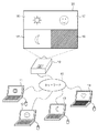
図1において、本実施形態の画像表示システムは、プロジェクタ10と複数のPC11、12、13、14がLANなどのネットワーク15を介して通信可能に接続されている。ここで、PC11、12、13はプロジェクタ10へ画面データの送信を行っているが、PC14は接続のみの状態で画面データの送信は行っていない。プロジェクタ10の投影面20はPCごとに領域16、17、18、19に区切られており、領域16にPC11、領域17にPC12、領域18にPC13の画面データがそれぞれ表示されている。ここで領域19は表示するべき画面データがないので黒表示となっている。ここで画面データは、各PCのディスプレイに表示されている画像データである。
1, in the image display system of the present embodiment, a
なお、以下では、図1に示したシステムを前提とし、プロジェクタ10の画面構成がPC11からPC14のいずれかによって変更された場合を例として説明を行う。
In the following description, it is assumed that the screen configuration of the
なお、以下に説明するプロジェクタ及びPCの動作フローは、プロジェクタに記憶されたファームウェアのプログラム又はPCにインストールされたアプリケーションのプログラムにより処理が実行される。 The operation flow of the projector and PC described below is executed by a firmware program stored in the projector or an application program installed in the PC.
<プロジェクタ及びPCの機能及び構成>図2を参照して、本実施形態のプロジェクタ及びPCの機能及び構成について説明する。 <Function and Configuration of Projector and PC> The function and configuration of the projector and PC of this embodiment will be described with reference to FIG.
まず、PCの機能及び構成について説明する。PC(11〜14)は、各PCで表示する画像データがVRAM205に記憶され、表示制御部201がVRAM205から画像データを取得し、ディスプレイ211に表示する。
First, the function and configuration of the PC will be described. In the PCs (11 to 14), image data to be displayed on each PC is stored in the
PCとプロジェクタとの接続が確立されて、PCからプロジェクタへの画面データ送信処理が開始されると、表示制御部201はVRAM205から画像データを取得し、メモリ部207に転送する。メモリ部207に転送された画像データはPC11で設定された解像度に対応したサイズを有し、未圧縮のデータである。ネットワーク経由でのデータ転送では一般的に、プロジェクタ10で表示する画像データの解像度に合わせて画像データのリサイズ処理が実行される。またJPEG圧縮処理などを施すことも多い。これはデータ転送にかかる時間を削減し、プロジェクタ10で投影表示するスループットを向上させるためである。これらの処理を実現するために、メモリ部207に記憶された画像データは画像処理部202に転送され、リサイズ、圧縮などの画像処理が施される。画像処理部202により加工された画像データはメモリ部207に記憶され、通信部204によりプロジェクタ10へ送信される。ユーザインタフェース(IF)208は、ユーザがPC11に対して画面構成を変更するなどの各種操作を受け付ける入力部である。
When the connection between the PC and the projector is established and the screen data transmission process from the PC to the projector is started, the
PCを構成する上記各部は、制御バス209とデータバス210で接続されており、CPU203によって制御される。
Each unit constituting the PC is connected by a
プロジェクタ10は、ネットワーク15を介して接続されたPC11〜13から送信される画像データを通信部105によって受信する。通信部105は受信した画像データをメモリ部106に転送する。メモリ部106に転送された画像データは圧縮されているので、これを映像処理部102によって複号する。この複号方法は周知であるので詳細な説明は省略する。映像処理部102によって復号された画像データはメモリ部106に記憶され、投影処理部101に転送され、液晶パネルなどの表示部107に投影される。操作部104は、ユーザがプロジェクタ10に対して画面構成を変更するなどの各種操作を受け付ける入力部である。
The
プロジェクタ10を構成する上記各部は、制御バス108とデータバス109で接続されており、CPU103によって制御される。なお、各制御及び処理は、本実施形態のハードウェア構成には限定されない。例えば1つのハードウェアが複数の手段として機能してもよいし、複数のハードウェアが処理を分担することで、プロジェクタ10の各手段として機能してもよい。
Each unit constituting the
<動作説明>次に、複数のPCの画面データをプロジェクタで同時に投影する場合の動作について説明する。 <Explanation of Operation> Next, the operation when the screen data of a plurality of PCs are simultaneously projected by the projector will be described.
プロジェクタ10の画面構成の変更は、プロジェクタ10とネットワーク15を介して通信可能に接続中の各PCから可能である。PC11上のアプリケーションにより起動されるユーザIF208をユーザが操作することにより、プロジェクタの画面構成の変更命令が通信部204を介してプロジェクタ10に送信される。これをプロジェクタ10の通信部105が受信し、この命令に従ってメモリ部106に格納されているプロジェクタ画面構成情報が書き換えられる。投影処理部101は、プロジェクタ画面構成情報を参照して画像データのレイアウトを決定し、表示部107に投影する。またプロジェクタ画面構成の変更は、ユーザがプロジェクタ10の操作部104を介して操作することも可能である。操作部104によりプロジェクタ画面構成の変更が指示された場合にも、同様にメモリ部106に格納されているプロジェクタ画面構成情報が書き換えられる。ここで、プロジェクタ10に表示していたPCの画像データのうち表示を停止するPCに対しては、通信部105を介して画面データ送信停止命令が送信され、この命令を受信したPCでは、画面データの取得処理及び送信処理が停止される。
The screen configuration of the
<動作説明>図3を参照して、本実施形態の画像表示システムを構成するプロジェクタ及びPCの各動作について説明する。 <Description of Operation> With reference to FIG. 3, the operations of the projector and the PC constituting the image display system of this embodiment will be described.
図3(a)は、プロジェクタで複数のPCの画面データを同時に投影中において、PCからプロジェクタ画面構成の変更命令を受信した場合のプロジェクタの動作を示すフローチャートである。 FIG. 3A is a flowchart showing the operation of the projector when a projector screen configuration change command is received from the PC while the projector is simultaneously projecting screen data of a plurality of PCs.
図3(a)において、プロジェクタ10で画像表示プログラムが起動されると、まず、CPU103は、接続中のPCから画面構成変更命令を受信しているか判定する(S301)。この判定処理は、通信部105がプロジェクタ10と接続が確立されているPC11〜14のいずれかから画面構成変更命令を受信したか否かを検出することで実現される。画面構成変更命令を受信したことを通信部105が検出すると、CPU103は、画面構成の変更が可能か否かを判定する(S302)。具体的には、ユーザによってプロジェクタ10の画面構成の変更を許可しない(禁止する)モードに設定されていないか、画面構成の変更が実現可能か、接続中のPCから既に画面構成を固定する命令を受信していないか判定する。ここで、画面構成の固定について補足すると、本実施形態のように画面構成が可変なシステムを用いてプレゼンテーション等を行っている際に、誤った操作によって全画面から4分割の投影表示などになってしまうなどのトラブルを防ぐための機能のことである。
3A, when the image display program is activated in the
画面構成の変更が不可であれば(S302でNO)、画面構成の変更ができなかった旨を画面構成変更命令の送信元のPCに対して、通信部105を介して通知し(S306)、処理を終了する。一方、画面構成の変更が可能であれば(S302でYES)、画面構成変更処理を実施する。 If the screen configuration cannot be changed (NO in S302), the fact that the screen configuration could not be changed is notified to the PC that sent the screen configuration change command via the communication unit 105 (S306). The process ends. On the other hand, if the screen configuration can be changed (YES in S302), a screen configuration change process is performed.
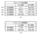
ここで画面構成変更処理について説明する。まず図4(a)は、図1に示した状況において、プロジェクタ10がメモリ部106で管理しているプロジェクタ画面構成情報を示している。プロジェクタ画面構成情報とはPCから受信した画像データをプロジェクタが投影可能な全領域の中のどの位置にどれくらいの大きさで表示するかを示すデータである。例えば、図1に示したように投影面20を4分割して画面を構成する場合、投影面全体の大きさを1600×1200pixelとすると、表示領域16〜19はこの投影面全体を4分割したものであり、図4(a)のように左上座標と右下座標が定まる。つまり表示領域16は図4(a)の23の行、表示領域17は24の行、表示領域18は25の行、表示領域19は26の行のようにそれぞれ記述されている。
Here, the screen configuration change process will be described. First, FIG. 4A shows projector screen configuration information managed by the
画面構成変更処理では、S301で受信した画面構成変更命令に従って上述したプロジェクタ画面構成情報が書き換えられる。なお、画面構成変更命令には、変更後の画面構成における各領域の座標が記述されてもよい。また、事前にプロジェクタとPCの間で、プロジェクタで設定可能な画面構成が送受信されていれば、画面構成1、画面構成2などのように具体的な画面構成情報と対応付けられたインディックス情報が記述されていてもよい。ここで説明の便宜上、図1に示した4分割画面表示から、図5に示す2分割画面表示に画面構成が変更されたとすると、プロジェクタ画面構成情報は図4(b)のように書き換えられる。
In the screen configuration change process, the projector screen configuration information described above is rewritten in accordance with the screen configuration change command received in S301. The screen configuration change command may describe the coordinates of each area in the changed screen configuration. In addition, if a screen configuration that can be set by the projector is transmitted and received between the projector and the PC in advance, index information associated with specific screen configuration information such as
図3(a)に戻り、CPU103は、画面構成情報が変更されたことをプロジェクタ10と接続中の全てのPCに対して通知する(S304)。これはプロジェクタの画面構成情報に従ってPC側で行う処理を変える必要があるため、PC側に現在のプロジェクタの画面構成情報を知らせることを目的としている。なお、S304において、画面構成の変更通知の受信完了を示すメッセージをPCから受信するまで、そのPCからの画面データを受け付けないように構成してもよい。
Returning to FIG. 3A, the
S305では、CPU103は、プロジェクタ画面構成変更前の状態で表示中であったPCをプロジェクタ画面構成変更後も継続して表示するかどうかを決定するために、まず表示中のPCがあるかどうかを判定する。ここで表示中のPCがなければ(S305でNO)、処理を終了し、表示中のPCがあればS306に進む(S305でYES)。
In S305, the
S306では、CPU103は、プロジェクタ投影面に画像データを表示中の各PCの表示を画面構成変更後に継続するか停止するかの判定を行う。この表示継続判定処理については後述するが、表示中のPCの表示を停止する判定がなされた場合には、そのPCに対して画面データの送信停止命令を送信する。この表示継続判定処理(S306)を表示中の全てのPCについて行い(S307、S308)、全てのPCに対して行った場合には(S307でYES)、本処理を終了する。
In S <b> 306, the
ここでS306での表示継続判定処理について説明する。 Here, the display continuation determination process in S306 will be described.
表示中のPCの表示を画面構成変更後も継続するか否かを判定するためには様々な方法が考えられる。第1には、画面構成変更前に表示中の全てのPCを画面構成変更後は表示停止にする方法がある。図6を用いて具体的に説明すると、変更前の図6(a)のように4分割画面に3つの画像データが表示されていたときに、2分割画面に変更されたとすると、変更後は図6(b)に示すように2分割された領域27、28には画像データの表示が行われない。
Various methods are conceivable for determining whether or not to continue the display of the PC being displayed even after the screen configuration is changed. First, there is a method of stopping display of all PCs being displayed before the screen configuration is changed after the screen configuration is changed. More specifically, with reference to FIG. 6, when three image data are displayed on the four-divided screen as shown in FIG. 6A before the change, if the image is changed to the two-divided screen, As shown in FIG. 6B, image data is not displayed in the
第2には、画面構成変更命令の送信元のPCについては表示を継続し、それ以外の表示中のPCについては表示停止にする方法がある。この場合、表示を継続するPCにおいて変更後の画面構成におけるどの領域に表示するのが適切であるか判定する必要がある。
この判定方法として、変更前の表示領域の位置と最も近い領域に表示を継続する方法、変更前の表示領域の大きさに最も近い領域に表示を継続する方法、変更後の最も大きな表示領域に表示を継続する方法などが考えられる。図6を用いて具体的に説明すると、変更前は図6(a)の4分割画面表示であったものが、表示領域16の画像データの送信元のPCからの指示によって、2分割画面表示に変更されたとする。この場合、変更後は図6(c)のように表示領域29には画面構成変更命令の送信元のPCからの画像データの表示が継続され、他の表示領域30の表示は停止され何も表示されない。
Second, there is a method in which display is continued for the PC that is the transmission source of the screen configuration change command, and display is stopped for other PCs that are currently displayed. In this case, it is necessary to determine in which area in the changed screen configuration it is appropriate for the PC that continues to display.
This judgment method includes a method of continuing display in the area closest to the position of the display area before the change, a method of continuing display in the area closest to the size of the display area before the change, and the largest display area after the change. A method of continuing the display can be considered. More specifically, FIG. 6 shows a four-divided screen display before the change, but a two-divided screen display in accordance with an instruction from the transmission source PC of the image data in the
第3には、画面構成変更後に表示可能なPCの台数までは、表示中のPCの表示を継続する方法がある。この方法では、画面構成変更前に表示可能なPCの台数より変更後に表示可能なPCの台数が多くなった場合には、表示中のPCの表示は全て継続される。反対に画面構成変更前に表示可能なPCの台数より変更後に表示可能なPCの台数が少なくなった場合には、いずれかのPCの表示を停止させる必要がある。表示を停止するPCの選択基準としては、プロジェクタとPCとの接続が確立された時刻や表示継続時間などが考えられる。また、上記選択基準に従ってPCを選択する際には、画面構成変更命令の送信元のPCを除くことも可能である。図6を用いて具体的に説明すると、変更前に図6(a)の4分割画面から2分割画面に変更されると、変更後は図6(d)に示すように2つの画像データまでが表示可能となる。このため、上記選択基準に従ってPC11〜13のうち1台のPCの表示が停止され、残り2つのPCの表示が継続される。
Thirdly, there is a method of continuing to display the displayed PC up to the number of PCs that can be displayed after the screen configuration is changed. In this method, when the number of PCs that can be displayed after the change is larger than the number of PCs that can be displayed before the screen configuration is changed, all the displayed PCs are continuously displayed. Conversely, when the number of PCs that can be displayed after the change is smaller than the number of PCs that can be displayed before the screen configuration is changed, it is necessary to stop the display of any PC. As selection criteria for the PC to stop the display, the time when the connection between the projector and the PC is established, the display duration time, and the like can be considered. Further, when selecting a PC in accordance with the selection criteria, it is possible to exclude the PC that is the transmission source of the screen configuration change command. More specifically, referring to FIG. 6, when the screen is changed from the 4-split screen of FIG. 6A to the 2-split screen before the change, up to two image data after the change, as shown in FIG. 6D. Can be displayed. Therefore, the display of one PC among the
上述した第1から第3の方法はプロジェクタによって一意に設定されていてもよいし、ユーザによっていずれかの方法が選択可能となっていてもよい。 The first to third methods described above may be uniquely set by the projector, or any one of the methods may be selectable by the user.
図8はS306の表示継続判定処理を示すフローチャートである。 FIG. 8 is a flowchart showing the display continuation determination process in S306.
図8において、CPU103は、プロジェクタ10の画面構成変更時の設定が上述した第1から第3の方法のいずれであるか判定する(S501、S503、S505)。
In FIG. 8, the
第1の方法ならば(S501でYES)、画面構成変更時に表示中の全てのPCの表示を停止させるので、現在表示中のPC(X)に対して画面データの送信停止命令を送信して、本処理を終了する(S502)。 If it is the first method (YES in S501), since the display of all PCs being displayed is stopped when the screen configuration is changed, a screen data transmission stop command is transmitted to the currently displayed PC (X). This process is terminated (S502).
第2の方法ならば(S502でYES)、画面構成変更命令の送信元のPCが表示中の場合には、そのPCの表示のみを継続し、残りのPCの表示を停止するので、現在表示中のPC(X)が画面構成変更命令の送信元であるかを判定する(S504)。判定の結果、画面構成変更命令の送信元であれば(S504でYES)、本処理を終了し、送信元でなければ(S504でNO)、S502で画面データの送信停止命令を送信して、本処理を終了する。 If it is the second method (YES in S502), if the transmission source PC of the screen configuration change command is being displayed, only the display of that PC is continued and the remaining PCs are stopped. It is determined whether the inside PC (X) is the transmission source of the screen configuration change command (S504). As a result of the determination, if it is the transmission source of the screen configuration change command (YES in S504), this process ends. If it is not the transmission source (NO in S504), a screen data transmission stop command is transmitted in S502, This process ends.
第3の方法ならば(S502でNO)、画面構成変更後に可能な限り多くのPCの表示を継続させるので、現在表示中のPC(X)の表示を停止させるか判定する(S505)。判定の結果、停止するならば(S505でYES)、S502で画面データの送信停止命令を送信し、停止させないならば(S505でNO)、本処理を終了する。S505の表示を停止するか否かの判定には図7に示すような表示中のPC情報を利用する。この表示中のPCに関する情報には、現在表示中のPCごとの、表示継続時間とプロジェクタとの接続確立時刻が含まれている。これらの情報は、システム起動時からプロジェクタ10のCPU103によって管理され、メモリ部106に保持されている。S505の判定には上記PC情報をメモリ部106から読み出して利用する。例えば、表示継続時間が最も短いPCに対して画面データ送信停止命令を送信する場合には、図7に示した表示中の3台のPCのうち、PC13に対して画面データ送信停止命令を送信する。
If it is the third method (NO in S502), since the display of as many PCs as possible is continued after the screen configuration change, it is determined whether or not the display of the currently displayed PC (X) is stopped (S505). As a result of the determination, if it is stopped (YES in S505), a screen data transmission stop command is transmitted in S502, and if it is not stopped (NO in S505), this process is terminated. The PC information being displayed as shown in FIG. 7 is used to determine whether or not to stop the display in S505. The information regarding the PC being displayed includes the display duration and the connection establishment time for each projector currently being displayed. These pieces of information are managed by the
図3(b)は、プロジェクタで複数のPCの画面データを同時に投影中におけるPCでの動作を示すフローチャートである。 FIG. 3B is a flowchart showing the operation of the PC while simultaneously projecting screen data of a plurality of PCs by the projector.
図3(b)において、PCでアプリケーションが起動されると、まず、CPU203は、ユーザIF208を介してPCを操作するユーザからプロジェクタの画面構成を変更する要求があるか判定する(S401)。画面構成の変更要求がある場合には(S401でYES)、CPU203は、変更後の画面構成に従って画面構成変更命令を生成し、通信部204を介して、プロジェクタ10に画面構成変更命令を送信する(S402)。
In FIG. 3B, when an application is activated on the PC, first, the
その後、CPU203は、通信部204を介して、プロジェクタ10から画面構成変更結果を受信するまで待つ(S403)。ここで画面構成変更結果とは、図3(a)のS306又はS304においてPCに通知される、プロジェクタの画面構成の変更が行われたか否かを示す通知や画面データ送信停止命令である。
Thereafter, the
S403で画面構成変更結果を受信した後(S403でYES)、プロジェクタ10から画面構成情報を受信した場合(S404のYES)、受信したプロジェクタの画面構成情報をメモリ部207に保持する(S405)。また、画面構成情報を受信しなかった場合(画面構成の変更が実施されなかった場合(S404でNO)、S405での処理をスキップして、S406に進む。なお、画面構成変更後のプロジェクタの画面構成情報をPC側で保持する理由は、プロジェクタで画面データを表示する領域の大きさに合わせて、PC側で取得した画像データをリサイズする際に利用するためである。 After receiving the screen configuration change result in S403 (YES in S403), if screen configuration information is received from the projector 10 (YES in S404), the received screen configuration information of the projector is held in the memory unit 207 (S405). If the screen configuration information has not been received (if the screen configuration has not been changed (NO in S404)), the processing in S405 is skipped and the process proceeds to S406. The reason why the screen configuration information is held on the PC side is that it is used when resizing the image data acquired on the PC side in accordance with the size of the area for displaying the screen data on the projector.
S406では、CPU203は、通信部204を介して、プロジェクタ10から画面データ送信停止命令を受信したか判定する。画面データ送信停止命令は、前述したように図3(a)のS306にてプロジェクタ10からPCに送信される。判定の結果、画面データ送信停止命令を受信した場合(S406でYES)、CPU203は、表示制御部201、画像処理部202、通信部204により実施されていた、画像データの取得、リサイズ、圧縮、送信の全ての処理を停止する(S407)。一方、画面データ送信停止命令を受信しなかった場合(S406でNO)、画面データの送信処理を継続する。ここで、あるPCによって画面構成が変更された場合、表示を停止する別のPCでは、ユーザに「他のPCによって画面構成が変更されたので、表示(画面データ送信)を停止する」ことを示すメッセージを提示する。この場合、プロジェクタ10から表示を停止するPCにのみメッセージを送信してもよい。
In step S <b> 406, the
本実施形態では、画面構成変更命令をプロジェクタ10と接続中のPCから受信する方法を例に説明したが、プロジェクタ10の操作部104によって画面構成が変更される構成としてもよい。この場合は、図3(a)のS301での処理が、操作部104によって画面構成変更が設定されたか監視する処理となる。また操作部104によって画面構成が変更された場合には、プロジェクタ自身が画面構成変更命令の送信元となるので、画面構成変更命令の送信元となるPCは存在しない。そのため、上述のように、画面構成変更命令の送信元のPCを優先的に表示継続と判定する処理は必要なくなる。
In the present embodiment, the method of receiving the screen configuration change command from the PC connected to the
本実施形態によれば、複数のPCの画面データをプロジェクタの投影面に同時に表示している場合に、画面構成の変更により同時表示可能な画面データ数が変更されても、ユーザに分かりやすい表示形態になるように表示を継続するか停止するかを判定する。 According to the present embodiment, when the screen data of a plurality of PCs are simultaneously displayed on the projection surface of the projector, even if the number of screen data that can be displayed simultaneously is changed due to the change in the screen configuration, the user-friendly display It is determined whether the display is continued or stopped so as to be in a form.
[他の実施形態]本発明は、以下の処理を実行することによっても実現される。即ち、上記実施形態の機能を実現するソフトウェア(プログラム)をネットワーク又は各種記憶媒体を介してシステム或いは装置に供給し、そのシステム或いは装置のコンピュータ(又はCPUやMPU等)がプログラムコードを読み出して実行する処理である。この場合、そのプログラム、及び該プログラムを記憶した記憶媒体は本発明を構成することになる。 [Other Embodiments] The present invention is also realized by executing the following processing. That is, software (program) that realizes the functions of the above-described embodiments is supplied to a system or apparatus via a network or various storage media, and a computer (or CPU, MPU, etc.) of the system or apparatus reads and executes the program code. It is processing to do. In this case, the program and the storage medium storing the program constitute the present invention.
Claims (10)
前記複数の装置と通信可能に接続する通信手段と、
前記通信手段を介して前記複数の装置からそれぞれ送信される画像データを受信する受信手段と、
前記受信手段により受信した画像データの表示領域を設定する画面構成手段と、
前記画面構成手段により設定された表示領域に対応する画像データを表示する表示制御手段と、を備え、
前記通信手段を介して前記複数の装置のいずれかから画面構成の変更命令を受信した場合、前記画面構成手段は当該命令に従って画面構成を変更し、前記通信手段は前記表示制御手段により現在表示中の画像データの送信元のすべての装置に画像データの送信停止命令を送信することを特徴とする画像表示装置。 In an image display device capable of receiving image data displayed on a plurality of devices and simultaneously displaying the received image data on a corresponding display area,
Communication means for communicably connecting to the plurality of devices;
Receiving means for receiving image data respectively transmitted from the plurality of devices via the communication means;
Screen configuration means for setting a display area of image data received by the receiving means;
Display control means for displaying image data corresponding to the display area set by the screen composition means,
When a screen configuration change command is received from any of the plurality of devices via the communication unit, the screen configuration unit changes the screen configuration according to the command, and the communication unit is currently displaying by the display control unit An image display device that transmits an image data transmission stop command to all the devices that transmit the image data.
前記通信手段を介して前記複数の装置からそれぞれ送信される画像データを受信する受信工程と、
前記受信工程により受信した画像データの表示領域を設定する画面構成工程と、
前記画面構成工程により設定された表示領域に対応する画像データを表示する表示工程と、を備え、
前記通信手段を介して前記複数の装置のいずれかから画面構成の変更命令を受信した場合、前記画面構成工程では当該命令に従って画面構成を変更し、前記通信手段は前記表示制御手段により現在表示中の画像データの送信元のすべての装置に画像データの送信停止命令を送信することを特徴とする制御方法。 An image display device having communication means for communicably connecting to a plurality of devices, capable of receiving image data displayed on the plurality of devices and simultaneously displaying the received image data in a corresponding display area Control method,
A receiving step of receiving image data respectively transmitted from the plurality of devices via the communication means;
A screen configuration step for setting a display area of the image data received by the reception step;
A display step of displaying image data corresponding to the display area set by the screen configuration step,
When a screen configuration change command is received from any of the plurality of devices via the communication unit, the screen configuration process changes the screen configuration according to the command, and the communication unit is currently displaying the display control unit. A control method comprising: transmitting an image data transmission stop command to all the devices that are the transmission sources of the image data.
前記制御方法は、
前記通信手段を介して前記複数の装置からそれぞれ送信される画像データを受信する受信工程と、
前記受信工程により受信した画像データの表示領域を設定する画面構成工程と、
前記画面構成工程により設定された表示領域に対応する画像データを表示する表示工程と、を備え、
前記通信手段を介して前記複数の装置のいずれかから画面構成の変更命令を受信した場合、前記画面構成工程では当該命令に従って画面構成を変更し、前記通信手段は前記表示制御手段により現在表示中の画像データの送信元のすべての装置に画像データの送信停止命令を送信することを特徴とするプログラム。 An image display device having communication means for communicably connecting to a plurality of devices, capable of receiving image data displayed on the plurality of devices and simultaneously displaying the received image data in a corresponding display area A program for causing a computer to execute the control method of
The control method is:
A receiving step of receiving image data respectively transmitted from the plurality of devices via the communication means;
A screen configuration step for setting a display area of the image data received by the reception step;
A display step of displaying image data corresponding to the display area set by the screen configuration step,
When a screen configuration change command is received from any of the plurality of devices via the communication unit, the screen configuration process changes the screen configuration according to the command, and the communication unit is currently displaying the display control unit. A program for transmitting an image data transmission stop command to all the devices that transmit the image data.
前記制御方法は、
前記通信手段を介して前記複数の装置からそれぞれ送信される画像データを受信する受信工程と、
前記受信工程により受信した画像データの表示領域を設定する画面構成工程と、
前記画面構成工程により設定された表示領域に対応する画像データを表示する表示工程と、を備え、
前記通信手段を介して前記複数の装置のいずれかから画面構成の変更命令を受信した場合、前記画面構成工程では当該命令に従って画面構成を変更し、前記通信手段は前記表示制御手段により現在表示中の画像データの送信元のすべての装置に画像データの送信停止命令を送信することを特徴とする記憶媒体。 An image display device having communication means for communicably connecting to a plurality of devices, capable of receiving image data displayed on the plurality of devices and simultaneously displaying the received image data in a corresponding display area A computer-readable storage medium storing a program for causing a computer to execute the control method of
The control method is:
A receiving step of receiving image data respectively transmitted from the plurality of devices via the communication means;
A screen configuration step for setting a display area of the image data received by the reception step;
A display step of displaying image data corresponding to the display area set by the screen configuration step,
When a screen configuration change command is received from any of the plurality of devices via the communication unit, the screen configuration process changes the screen configuration according to the command, and the communication unit is currently displaying the display control unit. A storage medium characterized by transmitting an image data transmission stop command to all the devices that transmit the image data.
Priority Applications (1)
| Application Number | Priority Date | Filing Date | Title |
|---|---|---|---|
| JP2011258214A JP6105841B2 (en) | 2011-11-25 | 2011-11-25 | Image display apparatus, control method therefor, program, and storage medium |
Applications Claiming Priority (1)
| Application Number | Priority Date | Filing Date | Title |
|---|---|---|---|
| JP2011258214A JP6105841B2 (en) | 2011-11-25 | 2011-11-25 | Image display apparatus, control method therefor, program, and storage medium |
Publications (3)
| Publication Number | Publication Date |
|---|---|
| JP2013113936A JP2013113936A (en) | 2013-06-10 |
| JP2013113936A5 JP2013113936A5 (en) | 2015-01-15 |
| JP6105841B2 true JP6105841B2 (en) | 2017-03-29 |
Family
ID=48709554
Family Applications (1)
| Application Number | Title | Priority Date | Filing Date |
|---|---|---|---|
| JP2011258214A Active JP6105841B2 (en) | 2011-11-25 | 2011-11-25 | Image display apparatus, control method therefor, program, and storage medium |
Country Status (1)
| Country | Link |
|---|---|
| JP (1) | JP6105841B2 (en) |
Families Citing this family (1)
| Publication number | Priority date | Publication date | Assignee | Title |
|---|---|---|---|---|
| JP2019015834A (en) | 2017-07-06 | 2019-01-31 | セイコーエプソン株式会社 | Display and method for controlling display |
Family Cites Families (4)
| Publication number | Priority date | Publication date | Assignee | Title |
|---|---|---|---|---|
| JP2004133354A (en) * | 2002-10-15 | 2004-04-30 | Seiko Epson Corp | Image display system, image display device, image data output device, image display method, image display program and image data output program |
| JP5375338B2 (en) * | 2009-05-29 | 2013-12-25 | セイコーエプソン株式会社 | Image display system, image display apparatus, image display method, image supply apparatus, and program |
| JP5522381B2 (en) * | 2010-03-15 | 2014-06-18 | セイコーエプソン株式会社 | Display device, terminal device, display system, program, information storage medium, display method, and image change method |
| JP2011215530A (en) * | 2010-04-02 | 2011-10-27 | Seiko Epson Corp | Method of controlling projection screen, projector system, projector and program |
-
2011
- 2011-11-25 JP JP2011258214A patent/JP6105841B2/en active Active
Also Published As
| Publication number | Publication date |
|---|---|
| JP2013113936A (en) | 2013-06-10 |
Similar Documents
| Publication | Publication Date | Title |
|---|---|---|
| US20040222983A1 (en) | Information processing apparatus and program | |
| JP2008089886A (en) | Wireless transmission method | |
| JP2006215531A (en) | Information processing device, information processing method, storage medium and program | |
| US10733954B2 (en) | Method of processing display data | |
| JP2011191499A (en) | Display device, terminal device, display system, program, information memory medium, display method and image alteration method | |
| EP2824936A1 (en) | Projector, projector control method, and recording medium storing projector control program | |
| JP6031750B2 (en) | Display control apparatus, image display system, display control method, and program | |
| JP2011159068A (en) | Information processing apparatus, and audio output control method for information processing apparatus | |
| US9307210B2 (en) | Image output apparatus, method, and medium | |
| JP6105841B2 (en) | Image display apparatus, control method therefor, program, and storage medium | |
| WO2012008065A1 (en) | Display control device, display control method, and control system | |
| CN108780348B (en) | Image transmission apparatus, image transmission system, and method of controlling image transmission apparatus | |
| US10397531B2 (en) | Projector, display device, and display method | |
| JP2014022769A (en) | Image forming device, control method therefor, control program therefor, and image forming system | |
| US9235438B2 (en) | Image display apparatus, image display method, and computer program product | |
| JP5603675B2 (en) | Display device, display device control method, and program | |
| JP2005292876A (en) | Image display system | |
| JP2014048921A (en) | Display device, video output device, control method therefor | |
| JP6140928B2 (en) | Information processing apparatus, display control method, and program | |
| US11790828B2 (en) | Control method for display apparatus, display apparatus, and display system | |
| JP5932475B2 (en) | Image transfer apparatus and control method thereof | |
| JP3862519B2 (en) | Display device, program thereof, and program of each device in system including the same | |
| JP2009223106A (en) | Image display system and information processing device | |
| US20130335636A1 (en) | Method for outputting image and electronic device for using the same | |
| JP5246819B2 (en) | Information processing apparatus, screen display control method, and program |
Legal Events
| Date | Code | Title | Description |
|---|---|---|---|
| A521 | Written amendment |
Free format text: JAPANESE INTERMEDIATE CODE: A523 Effective date: 20141125 |
|
| A621 | Written request for application examination |
Free format text: JAPANESE INTERMEDIATE CODE: A621 Effective date: 20141125 |
|
| A977 | Report on retrieval |
Free format text: JAPANESE INTERMEDIATE CODE: A971007 Effective date: 20150909 |
|
| A131 | Notification of reasons for refusal |
Free format text: JAPANESE INTERMEDIATE CODE: A131 Effective date: 20151019 |
|
| A521 | Written amendment |
Free format text: JAPANESE INTERMEDIATE CODE: A523 Effective date: 20151217 |
|
| A131 | Notification of reasons for refusal |
Free format text: JAPANESE INTERMEDIATE CODE: A131 Effective date: 20160627 |
|
| A521 | Written amendment |
Free format text: JAPANESE INTERMEDIATE CODE: A523 Effective date: 20160810 |
|
| TRDD | Decision of grant or rejection written | ||
| A01 | Written decision to grant a patent or to grant a registration (utility model) |
Free format text: JAPANESE INTERMEDIATE CODE: A01 Effective date: 20170203 |
|
| A61 | First payment of annual fees (during grant procedure) |
Free format text: JAPANESE INTERMEDIATE CODE: A61 Effective date: 20170303 |
|
| R151 | Written notification of patent or utility model registration |
Ref document number: 6105841 Country of ref document: JP Free format text: JAPANESE INTERMEDIATE CODE: R151 |