JP6175611B2 - Circulating game machine - Google Patents
Circulating game machine Download PDFInfo
- Publication number
- JP6175611B2 JP6175611B2 JP2013142851A JP2013142851A JP6175611B2 JP 6175611 B2 JP6175611 B2 JP 6175611B2 JP 2013142851 A JP2013142851 A JP 2013142851A JP 2013142851 A JP2013142851 A JP 2013142851A JP 6175611 B2 JP6175611 B2 JP 6175611B2
- Authority
- JP
- Japan
- Prior art keywords
- launch
- ball
- game ball
- game
- firing
- Prior art date
- Legal status (The legal status is an assumption and is not a legal conclusion. Google has not performed a legal analysis and makes no representation as to the accuracy of the status listed.)
- Active
Links
Images


Description
本発明は、発射した遊技球を遊技機内で回収して再度発射位置へ誘導する循環式遊技機に関する。 The present invention relates to a circulating game machine that collects launched game balls in a game machine and guides them to a launch position again.
従来の遊技機では、遊技者の発射操作に応じて、1個の遊技球を発射位置に送り出し、発射位置の遊技球を発射装置が遊技領域に発射する構成となっているが、遊技球の送り出し直後に遊技者が発射操作部のスイッチをオフにする(例えば、発射操作部から遊技者が手を離すことでタッチセンサの検出がオフになる)ことで、発射位置に遊技球が残ってしまい正常な発射を行うことができなくなるということが問題視されている。 In the conventional gaming machine, according to the player's launch operation, one game ball is sent to the launch position, and the launch device launches the game ball at the launch position into the game area. Immediately after delivery, the player turns off the switch of the launch operation unit (for example, the touch sensor detection is turned off when the player releases the hand from the launch operation unit), so that the game ball remains at the launch position. The problem is that normal firing is impossible.
この問題に対して、球送り用駆動源の駆動により遊技に供する球を1個宛発射位置に供給する球送り装置と、球送り装置が送り出した球を検出する球計数センサと、発射位置に供給された球を発射用駆動源の作動により発射する打球発射装置と、遊技者が操作することにより打球発射装置を作動させる発射操作信号を送出する発射操作検出部を有する打球発射操作部と、該打球発射操作部の発射操作検出部からの発射操作信号を受けると球送り装置の球送り用駆動源を所定時間ずつ間欠的に作動し、球計数センサからの球供給信号を受けると球送り動作開始時からの所定時間内においては発射操作信号の停止に拘らず発射用駆動源を所定時間作動する一連の制御を行う発射制御手段と、を備える遊技機<特許文献1>が開発され、発射位置に遊技球が残ることを防止している。
To solve this problem, a ball feeding device that supplies a ball to be used for a game by driving a ball feeding drive source to a discharge position, a ball count sensor that detects a ball sent out by the ball feeding device, and a launch position. A striking ball launching device for launching the supplied ball by actuating a driving source for launching, a hitting ball launching operation unit having a launching operation detecting unit for sending a firing operation signal for operating the hitting ball launching device when operated by a player, Upon receiving a firing operation signal from the launching operation detection unit of the hitting ball launching operation unit, the ball feeding drive source of the ball feeding device is intermittently operated every predetermined time, and upon receiving a ball supply signal from the ball counting sensor, A gaming machine <
また、近年、所定数の遊技球を機内に封入し、該封入された遊技球を循環し、発射球数をIN数、入賞球数及びアウト球数をOUT数として計数し、IN数とOUT数との関係性により正常な遊技が行われているかを適宜管理(以下、IN・OUT管理ともいう。)する循環式遊技機に、不正対策の観点から注目が集まっている。 Also, in recent years, a predetermined number of game balls are enclosed in the aircraft, the enclosed game balls are circulated, the number of shot balls is counted as the IN number, the number of winning balls and the number of winning balls are counted as the OUT number, and the IN number and OUT Attention has been focused on circulation-type gaming machines that appropriately manage whether normal games are being played based on the relationship with numbers (hereinafter also referred to as IN / OUT management) from the standpoint of fraud countermeasures.
IN・OUT管理は、発射中又は発射停止から所定期間内であれば、IN数−OUT数<所定数の関係性であれば正常と判断し、発射停止から所定期間後であればIN数=OUT数の関係性であれば正常と判断し、それらの関係性にないときには異常と判断している。 IN / OUT management is determined to be normal if there is a relationship of the number of INs−the number of OUTs <a predetermined number, during launch or within a predetermined period from the stop of firing, and the number of INs = after a predetermined period after the stop of firing = If the relationship is the number of OUTs, it is determined to be normal, and if they are not related, it is determined to be abnormal.
そのため、発射レール上に遊技球が残ることによって上記した関係性が乱れ異常と判断されることで、遊技機による異常報知又はホールコンピュータへの異常信号の出力などが行われ、不正を行うことなく遊技をしていた善良な遊技者に不愉快な思いをさせる可能性があるという問題が生じる。 Therefore, the game ball remains on the launch rail and the above-mentioned relationship is disturbed and determined to be abnormal, so that an abnormality notification by the gaming machine or an output of an abnormal signal to the hall computer is performed without causing fraud. There is a problem that a good player who has played a game may make the player feel unpleasant.
IN・OUT管理を行う循環式遊技機においては、<特許文献1>の構成を用いることによって発射レール上に遊技球が残ることを防止できるが、発射用駆動源を所定時間作動する一連の制御における発射強度(遊技者が発射操作部から手を離した場合の発射強度)がどのように設定されるかは不明であり、発射強度によっては、遊技領域に到達できずに発射レール上に戻ってしまうことも想定され、問題を完全に解消できるとは言い難い。
In a circulating game machine that performs IN / OUT management, it is possible to prevent a game ball from remaining on the launch rail by using the configuration of <
そこで、本発明は、球送り装置の作動直後に遊技者が発射操作部から手を離すことによってスイッチ(タッチセンサ)がオフになることで発射レール上に球が残ってしまうことを防止すると共に、発射位置に遊技球が存在する状態で該遊技球の発射時に発射操作部のスイッチがオフになった状態であっても、好適な発射強度で発射レール上の遊技球を発射する循環式遊技機の提供を目的としてなされたものである。 Therefore, the present invention prevents the ball from remaining on the firing rail by turning off the switch (touch sensor) when the player releases his hand from the firing operation unit immediately after the operation of the ball feeding device. In a state in which a game ball is present at the launch position, a circulation game that launches the game ball on the launch rail with a suitable launch intensity even when the launch operation unit is switched off when the game ball is launched. It was made for the purpose of providing the machine.
請求項1記載の遊技機は、
所定数の遊技球を内部に封入し、発射した遊技球数と回収した遊技球数とを管理しながら遊技を行う循環式遊技機において、
発射位置の遊技球を遊技領域に発射する発射動作を行う発射手段と、
前記発射位置に遊技球を1個ずつ送り出す球送り手段と、
前記発射位置へと送り出された遊技球を検出する発射球検出手段と、
前記発射手段により遊技球を発射する際の発射強度を調節する発射強度調節手段と、
発射操作の有無を検出する操作検出手段と、
該操作検出手段による検出状態が検出から未検出に変化したときに、前記発射球検出手段が検出した遊技球が未だ発射されていないことを条件に、該変化時の前記発射強度を記憶する発射強度記憶手段と、を備え、
前記発射手段は、少なくとも、前記発射位置に遊技球があれば、前記操作検出手段の検出状態に拘らず該遊技球を発射する構成とし、該発射時に前記操作検出手段による検出状態が未検出である場合は、前記発射強度記憶手段が記憶する前記発射強度に応じて遊技球を発射する
ことを特徴とする循環式遊技機である。
The gaming machine according to
In a circulation type gaming machine that encloses a predetermined number of game balls inside and performs a game while managing the number of game balls launched and the number of game balls collected,
Launching means for launching a game ball at the launch position into the game area;
And the ball feeding means for feeding one by one the game ball to the firing position,
A launch ball detecting means for detecting a game ball sent to the launch position ;
A launch intensity adjusting means for adjusting a launch intensity when launching a game ball by the launch means;
An operation detection means for detecting the presence or absence of the origination morphism operation,
When the detection state by the operation detection unit changes from detection to non-detection, the launching memorizes the launch intensity at the time of the change on condition that the game ball detected by the launching ball detection unit has not yet been launched. Strength storage means,
The launching unit is configured to launch the game ball regardless of the detection state of the operation detection unit if there is a game ball at the launch position, and the detection state by the operation detection unit is not detected at the time of the launch. In some cases, the game machine is configured to fire a game ball according to the firing strength stored in the firing strength storage means.
球送り手段は、遊技球が発射される発射位置に遊技球を1個ずつ送り出す構成であればよく、電気的に作動するアクチュエーターを駆動源として送り出してもよいし、遊技球の自重を用いて送り出してもよい。また、発射手段は、アクチュエーターを用いて遊技球を発射する構成が好適であり、球送り手段とタイミングを合わせることにより、単位時間に所定数の遊技球が一定の間隔で発射が可能となるように作動するのが好適である。 The ball feeding means may be configured to send out one gaming ball one by one to the launch position where the gaming ball is launched, and may send out an electrically operated actuator as a driving source, or using the weight of the gaming ball. You may send it out. The launching means is preferably configured to launch a game ball using an actuator, and by matching the timing with the ball feeding means, a predetermined number of game balls can be launched at regular intervals per unit time. It is preferable to operate.
発射手段は、球送り手段の実施から、送り出された遊技球の発射位置への移動が確実に終了するのに必要な時間が経過してから実施されるのが好適であり、該時間と発射手段を実施してから球送り手段を実施するまでの時間とを一定にすることにより、継続して発射操作を実施した場合は、一定の間隔で遊技球を発射する構成が好適である。また、球送り手段が実施されてから所定時間後に発射手段が実施されるため、球送り手段が実施されてから所定時間後には発射位置に遊技球は存在しない状態となる。 The launching means is preferably carried out after the time required for the movement of the delivered game ball to the launching position to end with certainty has elapsed since the implementation of the ball feeding means. A configuration in which the game ball is fired at regular intervals is preferable when the firing operation is continuously performed by making the time from the implementation of the means to the implementation of the ball feeding means constant. In addition, since the launching unit is implemented a predetermined time after the ball feeding unit is implemented, there is no gaming ball at the launching position after a predetermined time after the ball feeding unit is implemented.
発射球検出手段は、球送り手段によって送り出された遊技球が検出可能な構成であればよく、送り出された時点で検出してもよいし、送り出された遊技球が発射位置まで転動する途中で検出してもよいし、発射位置まで移動した時点で検出してもよい。また、送り出された遊技球は必ず発射される構成としたうえで、発射球検出手段が検出した遊技球を発射した遊技球と捉えて計数してもよい。 The fired ball detecting means may be configured so that the game ball sent out by the ball feeding means can be detected, and may be detected at the time when it is sent out, or while the sent game ball rolls to the launch position. Or may be detected when moving to the launch position. Further, the sent game balls may be always fired, and the game balls detected by the shot ball detecting means may be regarded as the launched game balls and counted.
発射強度調節手段は、発射強度の強弱を遊技者の操作によって調節できる構成であればよく、発射強度を調節する操作部の操作量や操作時間、及び操作方向によって発射強度の強弱が調節できればよく、例えば、ハンドルの回動量(回転方向)、ボタンの押下回数、ダイアルの回転量(回転方向)、レバーの操作時間(操作方向)、摺動スイッチの摺動量(摺動方向)、の操作に応じて調節してもよい。 The launch intensity adjusting means may be configured so that the strength of the launch intensity can be adjusted by the player's operation, and it is sufficient if the strength of the launch intensity can be adjusted by the operation amount, operation time, and operation direction of the operation unit for adjusting the launch intensity. For example, handle rotation (rotation direction), number of button presses, dial rotation (rotation direction), lever operation time (operation direction), sliding switch sliding amount (sliding direction) It may be adjusted accordingly.
操作検出手段は、遊技者が当該遊技機を遊技中、即ち、発射操作を実施中(発射強度を調節する操作部の操作中)であることを検出可能とする構成であればよく、発射強度を調節する操作部に遊技者が触れているか否か(遊技者が操作しているか否か)を検出するセンサとしてもよく、操作検出手段の検出は常時(割込み毎に)実施する処理となる。また、球送り手段も操作検出手段が遊技者の操作を検出していることを条件に実施されるが、発射強度が0に調整(遊技球を発射しないように調整)された状態では、操作検出手段が遊技者の操作を検出していても球送りは実施しない。 The operation detection means may be configured so as to be able to detect that the player is playing the game machine, that is, performing a launch operation (during operation of the operation unit for adjusting the launch intensity). It may be a sensor that detects whether or not the player is touching the operation unit that adjusts (whether or not the player is operating), and detection of the operation detection means is a process that is always performed (every interrupt). . Also, the ball feeding means is executed on the condition that the operation detecting means detects the player's operation, but in the state where the firing strength is adjusted to 0 (adjusted not to fire the game ball) Even if the detecting means detects the player's operation, the ball feeding is not performed.
発射強度記憶手段は、操作検出手段の検出状態の変化(検出から未検出に変化)に応じて発射強度を記憶するため、割込み毎に発射強度を記憶するか否かの判定を行ってもよく、検出から未検出に変化した時の発射強度は、例えば、回転させることによって発射強度を調節する一般的なハンドルタイプの発射操作部なら、ハンドルから手を離すとハンドルが自動で回転し発射強度0の状態に戻るが、手を離した瞬間に発射強度が0に戻るわけではなく、手を離した瞬間(例えば、割込処理が2msであった場合は手を離してから2ms後)の発射強度は、ハンドルの回動量を手で保持していたときと変化がない。従って記憶する発射強度は、操作検出手段が最後に遊技者の操作を検出した割込み時の発射強度としてもよいし、未検出になった時点の発射強度としてもよい。 Since the firing intensity storage means stores the firing intensity according to a change in the detection state of the operation detection means (change from detection to non-detection), it may be determined whether or not to store the firing intensity for each interrupt. The firing intensity when the detection changes from detection to non-detection is, for example, a general handle-type launch operation unit that adjusts the launch intensity by rotating the handle. It returns to the state of 0, but the firing intensity does not return to 0 at the moment of releasing the hand, but at the moment of releasing the hand (for example, 2 ms after releasing the hand if the interrupt processing was 2 ms) The firing strength is the same as when the handle is held by hand. Therefore, the firing intensity to be stored may be the firing intensity at the time of interruption when the operation detecting means detects the player's operation last time, or may be the firing intensity at the time when it is not detected.
また、発射強度が0に戻らないタイプの発射操作部(例えば、摺動スイッチタイプ)では、操作検出手段の検出が未検出になった時点の発射強度と直前の検出時の発射強度とで変化しないため、どちらの発射強度を記憶してもよい。 Further, in a launch operation unit (for example, a sliding switch type) whose launch intensity does not return to 0, it changes between the launch intensity at the time when the detection of the operation detection means is not detected and the launch intensity at the previous detection. Therefore, either firing intensity may be stored.
また、記憶する発射強度を直前の遊技球の発射に用いた発射強度としてもよく、その場合の発射強度記憶手段は、操作検出手段による検出状態が検出から未検出に変化したときに、前記発射球検出手段が検出した遊技球が未だ発射されていないことを条件に、前回の遊技球の発射に用いた前記発射強度を記憶する構成、となる。また、発射強度記憶手段は、検出状態が検出から未検出に変化したときに、発射球検出手段が検出した遊技球が未だ発射されていないことを条件に変化時の発射強度を記憶するが、この「発射球検出手段が検出した遊技球が未だ発射されていないこと」を、「球送り手段が送り出した遊技球が未だ発射されていないこと」に置換えてもよい。 Also, the memorized launch intensity may be the launch intensity used for launching the immediately preceding game ball. In that case, the launch intensity storing means is configured to release the launch when the detection state by the operation detecting means changes from detected to undetected. On the condition that the game ball detected by the ball detection means has not yet been fired, the launch intensity used for the previous launch of the game ball is stored. The firing strength storage means stores the firing strength at the time of change on the condition that the game ball detected by the shot ball detection means has not yet been launched when the detection state changes from detection to undetected. This “the game ball detected by the shot ball detecting means has not been fired yet” may be replaced with “the game ball sent by the ball feed means has not been fired yet”.
請求項1に記載の循環式遊技機では、球送り手段が実施されたことによって発射位置に遊技球が存在すれば、操作検出手段の検出状態に拘らず遊技球を発射する構成とした。これにより、発射位置(発射レール上)に遊技球が残存することを防止し、循環式遊技機においては、IN数とOUT数の関係性を正常に保ち、意図せず発生する不要な異常報知が回避され、遊技者に不快な思いをさせることがない。 In the circulating game machine according to the first aspect, when the ball is present at the launch position due to the implementation of the ball feeding means, the game ball is fired regardless of the detection state of the operation detection means. This prevents the game ball from remaining at the launch position (on the launch rail) and keeps the relationship between the number of INs and the number of OUTs normal in a recirculating game machine, and an unnecessary abnormality notification that occurs unintentionally Is avoided and does not make the player feel uncomfortable.
さらに、遊技球発射時に操作検出手段が遊技者の操作を未検出の場合(遊技者の操作に応じて球送り手段までは実施されたが、該球送り手段が実施されてから遊技球が発射されるまでの期間に、遊技者の操作が未検出となった場合)でも、該未検出になるまで遊技者が操作し調節していた発射強度に従って遊技球を発射するため、無駄な遊技球の発射をなくしながら遊技者の発射操作に応じた強度で確実に遊技領域まで遊技球を発射することができる。 Furthermore, when the operation detecting means has not detected the player's operation when the game ball is launched (the ball feeding means has been implemented according to the player's operation, but the game ball is launched after the ball feeding means has been implemented. Even if the player's operation has not been detected in the period until the game is performed), the game ball is fired according to the launch intensity that the player has operated and adjusted until the player has not been detected. Thus, it is possible to reliably launch the game ball to the game area with the strength according to the player's launch operation.
以下に本発明の好適な実施形態について説明する。尚、本発明の実施の形態は下記の実施例に何ら限定されるものではなく、本発明の技術的範囲に属する種々の形態を採ることができ、各実施例に記載された内容を適宜組み合わせることが可能なことはいうまでもない。 Hereinafter, preferred embodiments of the present invention will be described. The embodiments of the present invention are not limited to the following examples, and can take various forms belonging to the technical scope of the present invention, and the contents described in the respective examples are appropriately combined. It goes without saying that it is possible.
図1は、循環式遊技機(遊技球の機外への払出しを行わず、機内に遊技球を封入して遊技を行う)である循環式遊技機50の正面図である。図1に示すように、循環式遊技機50は、接続した台間ユニット100と隣り合わせで配置されている。台間ユニット100には、カード挿入口100aと、現金挿入口100bとが設けられており、カード挿入口100aにICカードを挿入するか現金挿入口100bに現金を挿入することで、循環式遊技機50に設けた球貸しボタン102aの操作が可能となる。
FIG. 1 is a front view of a circulation
また、循環式遊技機50は、縦長の固定外郭保持枠をなす外枠51にて各部を保持する構造を有している。外枠51の左側上下には、ヒンジ53が設けられていると共に、該ヒンジ53には内枠70が取り付けられており、内枠70は外枠51に対して開閉可能な構成になっている。
The circulating
また、内枠70には、ヒンジ53等により前枠52が開閉可能に取り付けられていると共に、この前枠52には、板ガラス61が取り外し自在に設けられており、板ガラス61の奥には、内枠70に取り付けられた遊技盤1が配されている。
A
前枠52の上部左右には、スピーカ(図示無し)が設けられており、循環式遊技機50から発生する遊技音が出力され、遊技者の趣向性を向上させる。また、遊技者の趣向性を向上させるために前枠52に遊技状態に応じて発光する枠側装飾ランプ(図示無し)も複数設けられている。また、前枠52の右下部には入賞表示装置20が配置され、後述する入賞口に遊技球が入賞すると、入賞口毎に設定された獲得遊技球数を表示する。
Speakers (not shown) are provided on the left and right of the upper part of the
前枠52の下方右側には遊技球の発射操作を行う発射操作ユニット107が配置され、その下には手置き台71が取付けられている手置き台71は、常時発射操作を行う遊技者の手を乗せておく台となる。
On the lower right side of the
発射操作ユニット107は、発射強度調整スイッチ部108と、遊技者が遊技球を発射するために操作する摺動操作部107aと、摺動操作部107aの上部に配置した発射停止スイッチ111と、発射強度を数値で示す発射強度表示部107bとで構成されている。
The
本実施例では、発射強度調整スイッチ部108に備えた摺動スイッチの抵抗値が遊技者の摺動操作部107aの操作に応じて変化することによって発射強度が調節可能となっている(本発明の発射強度調節手段に該当)。摺動操作部107aが最も左の位置にある場合は、発射強度が0となり遊技球の発射位置への球送りと発射は停止され、摺動操作部107aが最も右の40の位置にある場合は、遊技球の発射位置への球送りと最も強い発射強度の遊技球の発射とを行う。従って、摺動操作部107aを右に操作するほど遊技球を強い強度で発射する。なお、発射位置への球送りは、発射強度の強弱に関係なく一定の間隔(本実施例では600ms)で実施される。
In this embodiment, the firing strength can be adjusted by changing the resistance value of the sliding switch provided in the firing strength
発射強度表示部107bでは、摺動操作部107aの位置に応じた数値(発射強度表示)を常時表示する。また、摺動操作部107aにはタッチセンサ112(本発明の操作検出手段の一部に該当)が備えられている。本実施例では、発射強度が0以外の位置で摺動操作部107aに遊技者が触れている場合、タッチセンサ112が検出状態となり、発射装置87における発射待機部(発射位置)への遊技球の送り出し(球送りソレノイド130の作動)が行われ、送り出された遊技球が摺動操作部107aの位置に応じた発射強度で発射される。なお、タッチセンサ112を摺動操作部107aに備えず、他の遊技者が触れることができる位置に設けてもよい。
The firing
本実施例では、発射強度の調節に摺動スイッチを用いたが、もちろんこの構成に限るわけではなく、発射強度の強弱を遊技者の操作によって調節できる構成であればよく、例えば、ハンドルの回動量(回転方向)、ボタンの押下回数、ダイアルの回転量(回転方向)、レバーの操作時間(操作方向)の操作に応じて発射強度が調節される構成でもよい。 In this embodiment, the slide switch is used for adjusting the firing strength. However, the present invention is not limited to this configuration, and any configuration can be used as long as the strength of the firing strength can be adjusted by the player's operation. The firing intensity may be adjusted according to the operation of the amount of movement (rotation direction), the number of times the button is pressed, the amount of rotation of the dial (rotation direction), and the operation time of the lever (operation direction).
また、発射強度を固定する装置を設けてもよく、発射強度固定用のボタン(スイッチ)を備えたり、所定時間同一の発射強度が遊技者によって保持された場合、保持された強度に固定されるという構成でもよく、機械式として発射強度の調節部を固定することによって発射強度を固定する構成としてもよい。機械式の場合は、発射強度の調節部を固定箇所から操作すると、発射強度の固定は解除されるが、電子式の場合は、発射強度の調節部(本実施例では摺動操作部107a)が、固定した発射強度以外に操作された場合でも、発射強度を保持する構成(発射強度の固定解除には固定解除操作を実施)でもよいし、機械式と同様に発射強度の固定を解除する構成としてもよい。
In addition, a device for fixing the firing strength may be provided, and a button (switch) for fixing the firing strength may be provided, or when the same firing strength is held for a predetermined time by the player, the strength is fixed. It is also possible to adopt a configuration in which the firing strength is fixed by fixing the firing strength adjusting section as a mechanical type. In the case of the mechanical type, if the adjustment unit for the launch intensity is operated from a fixed position, the fixation of the launch intensity is released. However, in the case of the electronic type, the adjustment unit for the launch intensity (sliding
発射操作ユニット107の右上(循環式遊技機50の右端)には、内枠70と前枠52の両方の枠の開放が規制できるスライド錠を操作するシリンダ錠36が配置され、鍵が挿入可能となっている。このシリンダ錠36は、解錠するための鍵の種類を変更自在に行い得る可変式錠になっており、このような可変式錠を循環式遊技機50に使用することで、遊技店は、店に配置される全ての遊技機を店独自の鍵(1種類)に設定することが出来る。
A
発射操作ユニット107の左には、遊技者とのインターフェースとなるコントロール部8が設けられている。このコントロール部8には、タッチパネル式の液晶表示器となる操作部装置102と、計数スイッチ105と、遊技球数表示装置106が配置されている。操作部装置102のタッチパネル上には、球貸しボタン102aと、返却ボタン102bと、画面切換ボタン102cと、球貸しボタン102a及び返却ボタン102bの操作結果を示す操作結果表示部102dとが設けられている。
On the left side of the
コントロール部8を備える前板部も、ヒンジ53等によって内枠70から開閉可能となっているが、前枠52が前板部に被さる様に設置されているため、前枠52の開放時のみ前板部の開放が可能となる。
The front plate portion provided with the
また、図1は、板ガラス61の奥に位置する遊技盤1の遊技領域3の様子を概略的に示している。遊技領域3は、ガイドレール16によって囲まれた略円形の領域であると共に、多数の遊技釘が植設されており、遊技盤1の左上に配置した発射装置から発射された遊技球は、発射直後に遊技領域3を流下する構成となっている。
FIG. 1 schematically shows the state of the game area 3 of the
遊技領域3のほぼ中央部には、ワープ通路やステージ等が形成されたセンターケースや窓が設けられており、この窓の奥には、演出図柄表示装置6の液晶画面が配置される。また、これら以外にも、遊技領域3には、常時入賞可能な第1始動口11や、普通電動役物として構成された第2始動口12や、一般入賞口13、アタッカー式の大入賞口14等の役物(入賞口)や、アウト口15、特図表示装置、特図保留数表示装置等が設けられている。第1、第2特別図柄は共に遊技領域の隅に小さく表示されるだけであって、遊技領域の中央に設けられた演出図柄表示装置6にて特別図柄に対応した抽選結果の報知を行うとともに特別図柄の擬似演出を行い、その擬似演出によって遊技者に抽選結果に対しての期待感を与えている。
A center case and a window in which a warp passage, a stage, and the like are formed are provided in a substantially central portion of the game area 3, and a liquid crystal screen of the effect
上記のように遊技盤1を構成することによって、普通図柄作動ゲート17に遊技球が入球(普通図柄作動スイッチ17a(図3参照)が遊技球を検出)すると、普通図柄表示装置で普通図柄が変動表示を開始し、所定時間後に停止した普通図柄の態様に応じて、後述する普通電役ソレノイド12b(図3参照)を駆動させる。普通電役ソレノイド12bが駆動すると、ほぼ同期して普通電動役物の羽根部材が開放して、第2始動口12への入球(第2始動口スイッチ12a(図3参照)の検出)が可能となるように構成されている。尚、本実施形態におけるパチンコ機では、普通電動役物の羽根部材が駆動する開放時間は、通常時は0.2秒(1回)、時短状態(開放延長状態)では1.8秒(2回)である。また、第2始動口12は、普通電動役物の羽根部材が駆動しなければ遊技球が入球不可能な構成となっているが、この構成に限るわけではない。
By configuring the
次に、図2を用いて、本実施例における循環式遊技機50の遊技球の循環の仕組みを説明する。図2は循環の仕組みを背面から模式的に示した説明図となる。図2には、遊技球を循環させるための主な装置と、遊技球を揚上させる経路と、主な制御装置が記載されている。遊技球が発射されてから循環する流れを順を追って説明する。
Next, the mechanism of circulation of game balls of the circulation
発射可能な遊技球を循環式遊技機50(具体的には払出発射制御装置84)が管理(記憶)している状態で、摺動操作部107aが操作されると、球送りソレノイド130が作動し、遊技球を発射位置に送り出す(本発明の球送り手段に該当)。その際、発射装置87内に設けられた減算センサ131が、送り出した遊技球を発射球として検出(本発明の発射球検出手段に該当)し、発射可能な遊技球数から1を減算する。発射可能な遊技球数は、遊技球数表示装置106に表示され、減算センサ131の遊技球検出に応じて1を減算して表示する。
If the sliding
発射位置(本発明の発射位置に該当)に送り出された遊技球は、摺動操作部107aの位置(発射ソレノイド129作動時又は直前の球送りソレノイド130作動時の位置)に応じた発射強度で発射ソレノイド129の作動により遊技領域3に発射される。循環式遊技機50では、発射装置87の位置(遊技球を発射する位置)が遊技領域3を表から見て左上部となるため、従来機のように、発射された遊技球がガイドレールで形成された発射経路によって打ち上げられることがなく、発射ソレノイド129によって弾球された遊技球は、弾球直後に遊技領域3に到達する構成となる。
The game ball sent out to the launch position (corresponding to the launch position of the present invention) has a launch intensity according to the position of the sliding
遊技領域3に到達した遊技球は、遊技領域3を流下し、第1始動口11、第2始動口12等の入賞口に入球するか、或いは、アウト口15に入球する。いずれかの入賞口に入賞した遊技球は、遊技盤1の裏面を流下し誘導経路に配置された入賞検出センサ124に検出され、アウト口15に入球した遊技球は非入賞検出センサ125に検出される。入賞検出センサ124、又は非入賞センサ125が遊技球を検出するとアウト球数として加算され、このアウト球数と発射球数(減算センサ131検出球数)とにより遊技球循環の管理が行われる。上記した各センサは払出発射制御装置84に接続されているため、各センサの検出に応じた球循環は払出発射制御装置84によって管理される。
The game ball that has reached the game area 3 flows down the game area 3 and enters a winning opening such as the
入賞検出センサ124、又は非入賞センサ125が検出した遊技球は玉磨き装置85に繋がる誘導経路を流下する。玉磨き装置85では、カセットモータ114、研磨モータ115、カセットスイッチ116、研磨モータセンサ117を備え、研磨布を搭載したカセットを使用し、遊技球の研磨を実施する。また、研磨布を搭載したカセットの検知が行われる。
The game balls detected by the winning
遊技球の研磨は、研磨モータ115を動作させて遊技球を研磨布に押し付けるように動かすことにより実施される。研磨布はカセットに搭載した構造で交換可能となっており、カセットモータ114を使用して一定周期で布を巻き取るように作動させる。また、カセットスイッチ116により、研磨布を搭載したカセットの有無を検知する。
The polishing of the game ball is performed by operating the polishing
研磨された遊技球は、球磨き装置85から誘導経路を経て揚上装置86に誘導される。揚上装置85は、揚上発射モータ119、揚上発射モータ監視センサ121、揚上入口センサ120を備え、循環式遊技機50の下部まで流下した遊技球を、発射装置87を配置した上部(発射球タンク40)まで揚上させる。
The ground game ball is guided from the ball polishing device 85 to the lifting device 86 through a guide path. The lifting device 85 includes a lifting and launching
本実施例の循環式遊技機50では、揚上装置86に誘導された遊技球を、揚上発射モータ119を用いて、循環式遊技機50の上部に配置されている発射球タンク40まで打ち上げる構成となっている。揚上装置86では、揚上入口センサ120、発射入口センサ131により、揚上発射モータ119の遊技球発射位置と揚上経路の出口(発射球タンク40の入口)とに遊技球が存在するか否かを検出し、該検出結果に応じて揚上発射モータ119を駆動させる。揚上発射モータ119の駆動によって発射された遊技球は、図に示す、封入球打上げ揚上経路の最上部の曲面に接触することより飛球経路が変化し、飛球速度が減速して発射球タンク40に達する。揚上発射モータ監視センサ121は、揚上モータ119が正常な発射動作を行っているか検出する。
In the circulating
上記した構成により、本実施例の循環式遊技機50では、揚上装置86に誘導された遊技球は、揚上動作(揚上発射モータ119による球の打ち上げ)の実施直後に発射球の待機する発射球タンク40に移動する。従って、螺旋構造の揚上装置や、ベルトによる揚上装置のように揚上経路上に複数の遊技球が存在することがないため、遊技を待機せざるを得ない遊技球の数を減少させ、結果的に循環式遊技機50内で循環させる封入球数を減らすことが可能となっている。
With the above-described configuration, in the circulating
発射球タンク40まで揚上された遊技球は、転動して発射装置87に至るが、発射装置87への発射球誘導路を兼ねる封入球数計数経路に配置された適正量センサ123と満タンセンサ126とで遊技球を検出し、循環に必要な遊技球数を管理して過不足を検出すると報知を行う構成となっている。この場合の報知は、台間ユニット100を介して機外の管理装置に信号を出力すると共に、循環式遊技機50が備える表示装置(演出図柄表示装置6およびタッチパネル式液晶表示器)に遊技球の過不足を表示する。
The game ball that has been lifted up to the launch ball tank 40 rolls to the
次に、循環式遊技機50の電気的構成を図3、4に示したブロック図を用いて説明する。詳細な図示は省略するが、主制御装置80、払出発射制御装置84、演出図柄制御装置82(本発明の表示制御手段に該当)、サブ統合制御装置83、はいずれもCPU、ROM、RAM、入力ポート、出力ポート等を備えている。
Next, the electrical configuration of the circulation
図3に示す主制御装置80を中心にしたブロックでは、主制御装置80には、遊技盤中継端子板74を介して、第1始動口11に入球した遊技球を検出する第1始動口スイッチ11a、第2始動口12に入球した遊技球を検出する第2始動口スイッチ12a、普通図柄作動ゲート17に進入した遊技球を検出する普通図柄作動スイッチ17a、大入賞口14に入球した遊技球を検出するためのカウントスイッチ14a、一般入賞口13に入球した遊技球を検出する一般入賞口スイッチ13a、遊技球の流下方向に影響を与える磁力を検出する磁力センサ91、同様に遊技球の流下方向に影響を与える振動を検出する振動センサ92、上記した入賞口の検出スイッチを誤動作させる電波を検出する電波センサ93等の検出信号が入力される。
In the block centering on the
主制御装置80は、搭載しているプログラムに従って動作し、上記した検出信号などに基づいて遊技の進行に関わる各種のコマンドを生成してサブ統合制御装置83に出力する。また、主制御装置80は、図柄表示装置中継端子板90を介して接続されている第1特図表示装置9、第2特図表示装置10及び普通図柄表示装置7の表示、第1特図保留数表示装置9a、第2特図保留数表示装置10a、普図保留数表示装置8の点灯を制御する。
The
更に、主制御装置80は、大入賞口ソレノイド14bを制御することで大入賞口14の開閉を制御し、普通電動役物ソレノイド12bを制御することで第2始動口12の開閉を制御し、入賞口への入賞を検出すると入賞口毎に設定された獲得遊技球数を入賞表示装置20に表示する。各入賞口に入賞した遊技球の個数と各入賞口に設定された獲得遊技球数を、払出発射制御装置84に一定間隔毎にシリアル信号(コマンド形式)で送信する構成としてもよい。
Further, the
サブ統合制御装置83は、主制御装置80から送信されてくるデータ及びコマンドを受信し、それらを演出表示制御用、音制御用及びランプ制御用のデータに振り分けて、演出表示制御用のコマンド等は演出図柄制御装置82に送信し、音制御用及びランプ制御用は自身に含まれている各制御部位(音声制御装置及びランプ制御装置としての機能部)に分配する。そして、音声制御装置としての機能部は、音声制御用のデータに基づいて音LSIを作動させることによってスピーカか66らの音声出力を制御し、ランプ制御装置としての機能部はランプ制御用のデータに基づいてランプドライバを作動させることによって各種LED、ランプ26を制御する。
The
演出図柄制御装置82は、サブ統合制御装置83から受信したデータ及びコマンド(共に主制御装置80から送信されてきたものとサブ統合制御装置83が主制御装置80からの入力に基づいて生成したものとがある)に基づく制御を行い、擬似図柄等の演出画像を演出図柄表示装置6の画面に表示させる。尚、サブ統合制御装置83と主制御装置80とは間に演出中継端子板65を介した主制御装置80からサブ統合制御装置83への一方向通信回路として構成され、サブ統合制御装置83と演出図柄制御装置82とはサブ統合制御装置83から演出図柄制御装置82への一方向通信回路として構成されている。
The effect
次に、図4を用いて、主制御装置80と双方向通信が可能に接続された払出発射制御装置84を中心としたブロックを説明する。払出発射制御装置84は、搭載しているプログラムに従って動作し、主制御装置80から上述した獲得遊技球数の要求を示すコマンドを受信すると、要求された獲得遊技球数を発射可能な遊技球数へ加算し、加算した値を遊技球数表示装置106に表示する。また、後述する操作に応じた信号又は、センサの検出に応じた信号に基づいて、貸球の加算、遊技球の発射、遊技球の研磨、遊技球(封入球)の循環、等を制御する。
Next, referring to FIG. 4, a block centering on the dispensing
払出発射制御装置84に台間ユニット100及び操作部接続基板101を介して接続された操作部装置102となるタッチパネル式の液晶表示器には、前述したように球貸しボタン102aと、返却ボタン102bと、画面切換ボタン102cと、球貸しボタン102a及び返却ボタン102bの操作結果を示す操作結果表示部102dとが設けられている。この循環式遊技機50に設けられたタッチパネル式の液晶表示器の電源は、台間ユニット100から供給される。
As described above, the touch panel type liquid crystal display serving as the
また、タッチパネル式液晶表示器には、台間ユニット100に挿入されたICカード(又は会員カード)に記録されているカード情報や循環式遊技機50の遊技情報(遊技履歴等)を表示する機能も備えている。
In addition, the touch panel type liquid crystal display has a function of displaying card information recorded on an IC card (or membership card) inserted in the
操作部装置102の球貸しボタン102aを操作すると、タッチパネル操作情報として貸球数の加算を要求する信号が台間ユニット100を介して払出発射制御装置84に入力され、払出発射制御装置84は、該入力によって要求された貸球数を発射可能な遊技球数に加算し、加算した値を遊技球数表示装置106に表示する。この時、遊技球数表示装置106の加算状況に応じて貸球動作の結果内容を操作結果表示部102dに表示する。なお、一回の球貸しボタン102aの操作に対しては、予め設定された所定額(例えば、500円)に応じた貸球数(例えば、125個)を要求する。
When the
操作部装置102の返却ボタン102bを操作すると、タッチパネル操作情報としてICカードの返却動作を要求する信号が台間ユニット100に入力され、台間ユニット100から払出発射制御装置84に入力される。その時の循環式遊技機50の状態がICカードの返却が可能な状態であるか否かに応じて返却の可否と返却結果を操作結果表示部102dに表示する。返却可能な状態であれば、操作結果表示部102dに返却が可能であることが表示され、ICカードが台間ユニット100から排出される。
When the return button 102b of the
操作部装置102の画面切換ボタン102cを操作すると切換回路101aが作動し、タッチパネル式液晶表示器に表示する情報を、台間ユニット100から受信した情報から循環式遊技機50の演出図柄制御装置82から受信した情報(画像含む)へ切り替える。この切り替えに応じて、演出図柄表示装置6には台間ユニット100からの情報が表示される。
When the
台間ユニット100と操作部接続基板101とは相互通信が可能に接続され、演出図柄制御装置82と操作部装置102とは、互いに操作部接続基板101と相互通信が可能に接続されている。なお、封入式遊技機50からホールコンピュータ88への全ての出力は、台間ユニット100を介して行われるため、台間ユニット100も封入式遊技機50を管理することが可能な構成となっている。但し、この構成に限らず、台間ユニット100を介さずにホールコンピュータ88に出力する構成も考えられ、台間ユニット100の制御内容を遊技媒体の管理に限定してもよい。
The
循環式遊技機50内においては、払出発射制御装置84には操作部中継基板103が相互通信可能に接続され、操作部中継基板103には相互通信可能に遊技球数表示基板104が接続されている。遊技球数表示基板104には、計数スイッチ105と遊技球数表示装置106が配置され、計数スイッチ105の操作信号が払出発射制御装置84に入力され、払出発射制御装置84の出力に応じて遊技球数表示装置106に発射可能な遊技球数が表示される。
In the circulation
計数スイッチ105が操作されると、発射可能な遊技球数から所定球数を減算し、台間ユニット100に減算した所定球数を送信する(ICカードに所定数を記憶)。この時、遊技球数表示装置106に表示される数値も計数スイッチ105の操作に応じて減算される。計数スイッチ105の操作によって発射可能な遊技球数が0になると、台間ユニット100に挿入されているICカードの返却が可能となる。なお、計数スイッチ105の1回の操作で全ての発射可能な遊技球数を台間ユニット100に送信(発射可能な遊技球数が0)する構成としてもよい。
When the counting
また、払出発射制御装置84には、裏配線中継端子板75を介して、前枠閉鎖スイッチ18、内枠閉鎖スイッチ19からの検出信号が入力され、操作部中継基板103を介して、発射操作ユニット107が相互通信可能に接続され、発射操作ユニット107では、前述したように、発射強度調節スイッチ108、発射停止スイッチ111、タッチセンサ112、からの信号が払出発射制御装置84へ入力され、発射強度表示装置109の表示が払出発射制御装置84によって制御される。本実施例においては、前枠閉鎖スイッチ18、内枠閉鎖スイッチ19からの検出信号は払出発射制御装置84に入力される構成としたが、主制御装置80に入力する構成としてもよい。
In addition, detection signals from the front
また、払出発射制御装置84には、相互通信可能に接続された研磨中継基板113を介して、カセットスイッチ116、研磨モータセンサ117の検出信号が入力され、払出発射制御装置84は研磨中継基板113を介してカセットモータ114、研磨モータ115の駆動を制御する。
Further, detection signals of the
また、研磨中継基板113と相互通信可能に接続された揚上中継基板118を介して、払出発射制御装置84には、揚上入口センサ120、揚上モータ監視センサ121からの検出信号が入力され、払出発射制御装置84は前述した揚上発射モータ119の駆動を制御する。
In addition, detection signals from the lifting inlet sensor 120 and the lifting motor monitoring sensor 121 are input to the dispensing
また、内枠中継基板122は、内枠中継基板122から研磨中継基板113へと一方向通信が可能に接続され、内枠中継基板122には、前述した、適正量センサ123、入賞検出センサ124、非入賞検出センサ125、満タンセンサ126と、夜間監視スイッチ127とが接続され、各センサ又はスイッチからの信号が払出発射制御装置84に入力される。
The inner
夜間監視スイッチ127は、夜間(営業時間外)の扉開放を伴う不正を判断するための装置であり、電源基板に搭載されたバックアップ電源により、電源がオフの状態であっても内枠70の開放を監視可能とし、払出発射制御装置84が夜間の内枠70の開放回数情報を記憶し、電源投入時に開放回数情報を主制御装置80を介して機外に出力する構成となっている。
The
また、研磨中継基板と相互通信が可能に接続された発射中継基板128を介して、払出発射制御装置84には、減算センサ131、発射入口センサ132の検出信号が入力され、同様に発射中継基板128を介して払出発射制御装置84は、球送りソレノイド130の駆動を制御する。
Further, detection signals of the
次に、図5を用いて、発射装置87内の球送りと発射の機構を説明する。球送りは、球送りソレノイド130の駆動により球送り片aが可動することによって行われ、遊技球の発射は、破線で示した発射ソレノイド129(ロータリーソレノイド)の駆動によって発射ハンマーが作動することにより、発射待機部(発射位置)から遊技領域3に発射される。この場合、最低の発射強度に調節されていても、発射レール上からは飛び出す強度で弾球される。
Next, the ball feeding and launching mechanism in the
図5(1)は、球送りソレノイド130が未作動で遊技球が球送りを待機している状態を示している。球送りソレノイド130が未作動の場合は、球送り片aが軸を中心にして下部に下がった状態となり、球送り片aの右端上部が壁となって発射球誘導路からの遊技球を停止させた状態となる。
FIG. 5A shows a state where the
図5(2)は、球送りソレノイド130が作動し、該作動に伴い球送り片aの右端が軸を中心に上昇した状態を示している。この状態では、球送り片aの凹部内に発射球誘導路から遊技球を1個収納する。(3)は(2)の球送りソレノイド130の作動が終了した状態を示し、球送りソレノイド130の作動の終了に伴って、球送り片aの右端が再び下降するが、最下部まで下降した時点で、凹部内に収納された遊技球が図の奥側に転動することによって発射レール上に乗り、発射レールの傾斜に従って発射待機部(本発明の発射位置に該当)まで更に転動し停止する。従って、球送りソレノイド130が1回の動作を実施することにより、発射球誘導路の1個の遊技球が上記した遊技球の転動経路(以下「球送り経路」ともいう)を転動し発射位置に至る構成となる。
FIG. 5 (2) shows a state in which the
また、遊技球が球送り片aの凹部内から図面奥側に転動し発射レールに乗った時点で、減算センサ131が発射球として遊技球を検出する。発射ソレノイド129は、後述する遊技球発射処理によって、球送りソレノイド130が作動してから400ms後に作動し、該作動に伴い発射ハンマーが発射待機部の遊技球を遊技領域3に発射する。
Further, when the game ball rolls from the inside of the recess of the ball feed piece a to the back side of the drawing and gets on the launch rail, the
次に、図6を用いて、払出発射制御装置84が実行する持球加減算処理を説明する。持球加減算処理は、封入式遊技機50が記憶する発射可能な遊技球数を管理する処理となる。持球加減算処理を開始すると、減算センサ131が遊技球を検出したか、即ち、球送りソレノイド130の作動によって球送り経路上で遊技球が検出されたか否かの判定を行うが、本実施例では発射待機部に送り出された遊技球は必ず発射ソレノイド129の作動によって遊技領域3に発射されるため、この判定は遊技球を発射したか否かの判定となる(S10)。肯定判定なら(S10:yes)、持球カウンタから1を減算する(S15)。持球カウンタは、発射可能な遊技球数を記憶する装置であり、持球カウンタの値(発射可能な遊技球数)は遊技球数表示装置106に表示され、持球カウンタの値の変化に応じて表示内容(数値)も変化する。
Next, the ball addition / subtraction process executed by the payout /
S15、又はS10の否定判定(S10:no)に続いては、主制御装置80から第1始動口スイッチ11a、第2始動口スイッチ12a、カウントスイッチ14a、又は一般入賞口スイッチ13aの遊技球検出に応じた持球カウンタへの加算指示信号を受信したか否か判定する(S20)。否定判定なら(S20)リターンし、肯定判定なら(S20:yes)、受信した指示信号が示す賞球数を持球カウンタに加算し(S25)リターンする。
Following the negative determination in S15 or S10 (S10: no), the
本実施例では、主制御装置80から払出発射制御装置84に賞球数を示す指示信号を送信する構成としたが、どの入賞口に入賞したかを示す信号のみを主制御装置80から払出発射制御装置84に送信し、各入賞口に対応する賞球数は払出発射制御装置84で判断する構成としてもよい。
In the present embodiment, the
また、払出発射制御装置84は、S105の処理によって持球カウンタの値が10減算される毎に、台間ユニット100を介して機外のホールコンピュータ88に発射球数信号(100msのHi信号)を出力する構成となっている。また、払出発射制御装置84は、S25の処理によって加算される持球カウンタの値が、10加算される毎に台間ユニット100を介して機外のホールコンピュータ88に賞球数信号(100msのHi信号)を出力する構成(連続して出力する場合は100msのLowを経てから出力するため、持球カウンタの加算速度に応じて出力回数を記憶する構成)となっている。
In addition, every time the value of the ball counter is decremented by 10 in the process of S105, the
なお、本実施例では、持球カウンタの値が10個増加するごとに機外に賞球数信号を出力する構成としたが、持球カウンタへの加算処理(S25)が行われる毎に、加算した値を示す信号(コマンド)を台間ユニット100に送信する構成としてもよい。また、所定時間が経過するごとに、その間に増加した持球カウンタの値を台間ユニット100に送信する構成としてもよく、どのようなタイミングでどのような値を送信してもよいが、ホールに設置されたホールコンピュータ88の仕様に応じた形式が好ましい。
In the present embodiment, the prize ball number signal is output to the outside every time the value of the ball counter is increased by 10, but each time the addition process to the ball counter (S25) is performed, A signal (command) indicating the added value may be transmitted to the
次に、図7の図を用いて、払出発射制御装置84が実行するIN/OUT管理処理を説明する。IN/OUT管理処理を開始すると、減算センサ131が遊技球を検出したか否か判定する(S50)。肯定判定なら(S50:yes)、管理カウンタに+1し(S55)、否定判定(S50:no)、又はS55に続いては、入賞検出センサ124が遊技球を検出したか否か判定する(S60)。肯定判定なら(S60:yes)、管理カウンタから−1し(S65)、否定判定(S60:no)、又はS65に続いては、非入賞検出センサ125が遊技球を検出したか否か判定する(S70)。肯定判定なら(S70:yes)、管理カウンタから−1し(S75)、S70の否定判定(S70:no)、又はS75に続いては、管理カウンタの値が0か否か判定する(S80)。肯定判定なら(S80:yes)、管理フラグに0をセットして(S85)リターンし、否定判定なら(S80:no)、管理フラグに1をセットして(S90)リターンする。
Next, the IN / OUT management process executed by the payout /
管理カウンタは払出発射制御装置84が備える装置であり、管理カウンタの値によって遊技球の発射と回収の状況を管理する。管理カウンタの値が0であれば、発射した遊技球が全て回収された状態となる。
The management counter is a device provided in the payout
管理フラグも、払出発射制御装置84が記憶する値であり、値が0であれば、発射した遊技球が全て回収された状態であると判断し、値が1であれば、発射した遊技球が全て回収されていない状態であると判断する。従って、管理フラグが0であれば、遊技球の発射が停止されてから、少なくとも最後に発射した遊技球が遊技領域3の流下を終了するまでの時間が経過し、遊技領域3上には遊技球が存在しない状態であることを払出発射制御装置84が判断でき、管理フラグが1であれば、発射した遊技球が全て回収できていないと判断できる。従って、減算センサ131の検出が所定時間行われていない状態にも拘らず管理フラグの値が1である場合は、循環式遊技機50が備えた演出機器を用いて異常報知を実施すると共に台間ユニット100を介してホールコンピュータに異常状態を示す信号を送信する構成となっている。
The management flag is also a value stored by the payout
次に、図8を用いて、払出発射制御装置84が実行する前枠開放時処理を説明する。この前枠開放時処理は、前枠52の開閉状態に応じて、遊技球の発射を判断する処理となる。前枠開放時処理を開始すると、前枠閉鎖スイッチ18からの信号が閉鎖状態HI(1)から開放状態LOW(0)に変化したか否か、即ち前枠52が開放されたか否か判定する(S100)。否定判定なら(S100:no)リターンし、肯定判定なら(S100:yes)、前枠開放報知処理として、主制御装置80を介してサブ統合制御装置84に、演出機器において前枠52が開放していることを示す報知を実施する指示信号を出力し、台間ユニット100を介してホールコンピュータに前枠52が開放中であることを示す信号を出力する(S105)。続いて、球送りソレノイド130、発射ソレノイド129の作動を禁止する発射禁止処理を行い(S110)、前枠開放フラグに1を設定して(S115)、リターンする。
Next, with reference to FIG. 8, the front frame opening process executed by the payout
次に、図9を用いて、払出発射制御装置84が実行する前枠閉鎖時処理を説明する。この前枠閉鎖時処理も、前枠52の開閉状態に応じて、遊技球の発射を判断する処理となる。前枠閉鎖時処理を開始すると、前枠閉鎖スイッチ18からの信号が開放状態LOW(0)から閉鎖状態HI(1)に変化したか否か、即ち前枠52が開放状態から閉鎖されたか否か判定する(S150)。否定判定なら(S150:no)リターンし、肯定判定なら、前枠開放報知終了処理を行い(S155)。発射禁止終了処理を行うことによって遊技球の発射を可能とし(S160)、前枠開放フラグに0を設定して(S165)、リターンする。
Next, with reference to FIG. 9, the front frame closing process executed by the payout
本実施例においては、前枠開放処理及び前枠閉鎖処理を払出発射制御装置84が実行したが、主制御装置80が実行する構成としても何ら問題ない。
In the present embodiment, the dispensing
次に、図10を用いて払出発射制御装置84が実行する発射強度記憶処理を説明する。この処理は、本発明の発射強度記憶手段に該当する処理となる。発射強度記憶手段を開始すると、タッチセンサ112の検出状態が検出HI(1)から未検出LOW(0)に変化したか否か、即ち、遊技者が摺動操作部107aから手を離したか否か判定する(S200)。否定判定なら(S200:no)、リターンし、肯定判定なら(S200:yes)、球送りフラグが1か否か判定する(S205)。
Next, the firing intensity storage process executed by the payout
球送りフラグは、払出発射制御装置84が記憶する値であり、値が1なら、発射装置87において球送り動作(球送りソレノイド130が作動)が行われてから、該球送り動作によって発射待機部(発射位置)に送られた遊技球がまだ発射されていない状態であること(球送り動作が開始されてから発射されるまでの期間、即ち、球送り経路上か発射待機部に遊技球が存在する状態である)を、値が0なら、遊技球が発射されてから球送り動作が行われていない状態であることを払出発射制御装置84が判断する。
The ball feed flag is a value stored in the payout
S205が否定判定なら(S205:no)、リターンし、肯定判定、即ち、遊技者が摺動操作部107aから手を離した状態にもかかわらず、発射位置又は球送り経路に遊技球が残存する状態なら(S205:yes)、当該処理時の摺動操作部107aの位置に応じた発射強度を発射強度記憶領域に記憶する処理を行い(S210)リターンする。
If S205 is a negative determination (S205: no), the process returns and an affirmative determination is made, that is, the game ball remains at the launch position or the ball feed path regardless of the state where the player has released his / her hand from the sliding
本実施例においては、タッチセンサ112の検出状態が検出から未検出に変化しても、摺動操作部107aの位置に応じた発射強度は保持される構成となっているが、タッチセンサ112が未検出となった時点で発射強度がクリアされる構成ならば、発射強度を記憶してからクリアする構成とすればよい。
In this embodiment, even if the detection state of the
本実施例では、球送りソレノイド130が作動してから発射ソレノイド129が作動するまでの時間は400msの一定時間に設定されている。従って、球送り動作が実施されてから400ms以内に遊技者が摺動操作部107aから手を離すと、上記した発射強度の記憶処理S210が実施されることになる。
In this embodiment, the time from when the
遊技球を機外に払出す構成の弾球遊技機であれば、発射レール上に遊技球が残存したとしても、遊技者が1個の遊技球を損するのみであり、その後の遊技に支障をきたすことはないが、循環式遊技機の場合に発射レール上に遊技球が残存する状況が発生すると、図7を用いて説明したIN/OUT管理処理に基づいて異常状態であると判断してしまう。遊技者が意識的にレール上に遊技球を残すとは考え辛いため、循環式遊技機においては上記したタイミングで偶然手を離した場合でも好適に遊技球を発射する構成が必要となる。 In the case of a ball game machine configured to pay out a game ball to the outside, even if the game ball remains on the launch rail, the player only loses one game ball, which may hinder subsequent games. In the case of a recirculating game machine, if a situation occurs in which a game ball remains on the launch rail, it is determined that the state is abnormal based on the IN / OUT management process described with reference to FIG. End up. Since it is difficult for the player to consciously leave the game ball on the rail, the circulation type game machine needs to have a configuration for suitably launching the game ball even when the player accidentally releases the hand at the timing described above.
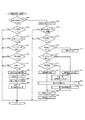
次に、図11を用いて、払出発射制御装置84が実行する遊技球発射処理1を説明する。この処理は、本発明の発射手段に該当し、球送り時発射強度記憶手段を含む構成となる。遊技球発射処理1を開始すると球送り作動タイマが0か否か判定する(S400)。
Next, the game
遊技者の発射操作が継続して行われれば、具体的には摺動操作部107aにおけるタッチセンサ112の検出が継続して実施されれば、発射待機部(発射位置)への球送りは、一定の時間(本実施例では600msだがこの時間に限るわけではない)が経過する毎に繰り返し実施される構成となっている。S400の判定は、上記した一定の時間が経過したか否かの判定となる。
If the player's firing operation is continuously performed, specifically, if the detection of the
S400が肯定判定、即ち、前回の球送りから600ms(以上)が経過し、次の球送り動作を開始してもよいタイミングなら(S400:yes)、前枠開放フラグが0か否か(S405)、持球カウンタの値が0よりも多いか否か(S410)、タッチセンサ112が発射操作を検出しているか否か(S415)、摺動操作部107aの調節位置が発射強度0よりも大きい発射強度に調節されているか(S420)、球送りフラグの値が0か否か(S425)判定する。
If S400 is affirmative, that is, if 600 ms (or more) has elapsed since the previous ball feed and the next ball feed operation may be started (S400: yes), whether or not the front frame release flag is 0 (S405). ), Whether the value of the ball holding counter is greater than 0 (S410), whether the
S405からS425のいずれかが否定判定なら(S405:no、S410:no、S415:no、S420:no、S425:no)リターンに抜け、全てが肯定判定なら、具体的には、前枠52が閉鎖され(S405:yes)、持球カウンタに発射可能な遊技球が存在し(S410:yes)、タッチセンサ112で発射操作が検出され(S415:yes)、摺動操作部107aが0よりも大きい発射強度に調節され(S420:yes)、発射ソレノイド129の作動により発射待機部に遊技球が存在しない状態なら(S425:yes)、球送りソレノイド作動処理を行い(S430)、発射待機部に遊技球を1個の遊技球を送り出す動作を開始する。
If any of S405 to S425 is negative determination (S405: no, S410: no, S415: no, S420: no, S425: no), if all are positive determinations, specifically, the
S430に続いては、球送りフラグに1を設定し(S435)、球送り作動タイマに600msに対応した値を設定(本実施例では、2ms毎に割込みを行うため設定する値は299となる)し(S440)、当該処理時の摺動操作部107aの調節位置に応じた発射強度を、球送り時発射強度として専用の記憶領域に記憶して(S445)(本発明の球送り時発射強度記憶手段に該当)リターンする。
Following S430, 1 is set in the ball feed flag (S435), and a value corresponding to 600 ms is set in the ball feed operation timer (in this embodiment, the value to be set is 299 because an interruption is performed every 2 ms). (S440), and the firing intensity corresponding to the adjustment position of the sliding
S400が否定判定、即ち、前回の球送り動作が実施されてから、まだ次の球送りタイミングが訪れていないなら(S400:no)、S440で設定した球送り作動タイマから−1するデクリメント処理を行い(S450)、デクリメント後の球送り作動タイマの値が所定値か否か判定する(S455)。 If S400 is negative, that is, if the next ball feed timing has not yet arrived since the previous ball feed operation was performed (S400: no), the decrement process is decremented by -1 from the ball feed operation timer set in S440. Is performed (S450), and it is determined whether or not the value of the decremented ball feed operation timer is a predetermined value (S455).
S455の判定は、球送り動作が実施されてから遊技球を発射するタイミングまで時間が経過したか否かの判定となり、本実施例では、球送り動作が実施されてから400msが経過すると、発射ソレノイド129が作動し、球送り動作によって発射待機部に送られた遊技球を発射する構成となっている。
The determination in S455 is a determination as to whether or not the time has elapsed from when the ball feeding operation is performed until the timing of launching the game ball. In this embodiment, when 400 ms has elapsed since the ball feeding operation was performed, the firing is performed. The
S455が否定判定なら(S455:no)、リターンし、肯定判定、即ち、遊技球を発射するタイミングなら(S455:yes)、前枠開放フラグが0か否か判定し(S460)、否定判定なら(S460:no)リターンし、肯定判定なら(S460:yes)、球検出フラグが1か否か判定する(S465)。 If S455 is a negative determination (S455: no), the process returns and affirmative determination is made, that is, if it is the timing to release a game ball (S455: yes), it is determined whether the front frame release flag is 0 (S460), and if it is a negative determination. (S460: no) It returns and if it is affirmation determination (S460: yes), it will be determined whether a ball | bowl detection flag is 1 (S465).
球検出フラグは、払出発射制御装置84が記憶する値であり、値で1なら減算センサ131が遊技球を検出してから発射ソレノイド129の作動が未実施であることを、値が0なら発射ソレノイド129が作動してから減算センサ131が遊技球を未検出であることを払出発射制御装置84が判断する。
The ball detection flag is a value stored in the payout
従って、S465が否定判定なら(S465:no)、球送り動作が実施されたにもかかわらず、減算センサ131が遊技球を検出できてない状態となり、発射装置87内、又は発射装置87に至る球経路上の球詰まりか、減算センサ131の故障が考えられるため、球送りエラーと判断し、遊技の進行を停止して循環式遊技機50が備える演出機器を用いてエラー報知を実施すると同時に、台間ユニット100を介してホールコンピュータ88に球送りエラー状態を示す信号を出力する(S470)。
Therefore, if S465 is negative (S465: no), the
S465が肯定判定なら(S465:yes)、タッチセンサ112が摺動操作部107aの操作を検出しているか否か判定する(S475)。肯定判定なら(S475:yes)、摺動操作部107aが0よりも大きい発射強度に調節されているか否か判定する(S480)。肯定判定なら(S480:yes)、当該処理中の発射強度を参照し(S485)、参照した発射強度に応じて発射ソレノイド129を作動し(S490)、球送りフラグと球検出フラグとに0を設定し(S495、S500)リターンする。上記したS475の肯定判定からS480の肯定判定を介した処理の流れが、通常(摺動操作部107aが絶えず遊技者の手によって保持されながら発射強度が0より大きい値に調節された状態)の遊技球発射処理の流れとなる。
If S465 is affirmative (S465: yes), it is determined whether or not the
一方、S475が否定判定であった場合、この状況は、発射待機部に既に遊技球が球送りされたにもかかわらず、発射待機部の遊技球発射時には遊技者が何らかの都合で摺動操作部107a(発射操作部)から手を離した状態となる。本実施例の循環式遊技機50では、図7を用いて説明したIN/OUTの関係性を乱さないために、発射待機部に遊技球が存在する場合、言い換えれば、発射待機部に遊技球が送り出された場合は、送り出してから発射ソレノイド129が作動する間にタッチセンサ112による摺動操作部107aの操作が未検出となっても、発射ソレノイド129を上記した通常と同様のタイミングで作動させ、発射待機部の遊技球を発射する構成となっている。
On the other hand, if S475 is a negative determination, this situation means that the player has somehow controlled the sliding operation unit at the time of launching the game ball, even though the game ball has already been fed to the launch standby unit. 107a (launching operation unit) is released. In the circulation
具体的には、S475が否定判定なら(S475:no)、図10のS210で記憶した発射強度記憶を参照し(S510)、該参照により確認した発射強度に応じて発射ソレノイド129を作動し遊技球を発射する(S490)。発射後は、S210で記憶した発射強度記憶を消去して(S515)S495に進むが、発射強度の消去は行わず、S210での記憶時に前回の記憶値を更新する構成としてもよい。
Specifically, if S475 is negative (S475: no), the firing intensity memory stored in S210 of FIG. 10 is referred to (S510), and the firing
本実施例では発射操作部に摺動式の操作部を採用しており、遊技者が摺動操作部107aから手を離しても摺動操作部107aが自動で発射強度が0の位置まで移動する構成とはなっていない。このように、遊技者が発射強度の調節中に発射操作部から手を離した場合でも、発射操作部が自動で発射強度0の位置まで戻らない構成の発射操作部であるならば、図10の発射強度記憶処理は行わずに、手を離した状態の発射操作部が示す発射強度を参照して発射ソレノイド129を作動させる構成としてもよく、その場合、遊技球が発射待機部に送り出された状況であれば、タッチセンサ112の検出判定を行わずに発射操作部の調節位置のみ参照すればよく、処理が簡素化できる。
In this embodiment, a sliding operation unit is adopted as the firing operation unit, and even if the player releases his / her hand from the sliding
フローチャートの説明に戻り、S480が否定判定であった場合、この状況は、発射待機部に遊技球を送り出した後、送り出した遊技球が発射される前に摺動操作部107aを発射強度0の位置に調節した状態となる。この状況においても、循環式遊技機におけるIN/OUTの関係性を乱さないために、発射ソレノイド129を上記した通常及びタッチセンサ112未検出時と同様のタイミングで作動させ、発射待機部の遊技球を発射する構成となっている。
Returning to the explanation of the flowchart, if S480 is negative, this situation means that after the game ball is sent out to the launch standby unit, the sliding
具体的には、S480が否定判定なら(S480:no)、S445で記憶した発射待機部へ遊技球を球送りする時点で記憶した球送り時発射強度記憶を参照し(S505)、該参照により確認した発射強度に応じて発射ソレノイド129を作動させて遊技球を発射し(S490)、S445で記憶した発射強度記憶を消去して(S515)S495に進むが、ここでも発射強度の消去は行わず、S445での記憶時に前回の記憶値を更新する構成としてもよい。
Specifically, if S480 is negative (S480: no), reference is made to the launch strength memory stored at the time of sending the game ball to the launch standby section stored in S445 (S505). The firing
以上が実施例1において払出発射制御装置84が実行する遊技球発射処理1となる。遊技球を機外に払出す従来機においては、発射待機部に遊技球が送り出されてから該遊技球が発射されるまでの間に、発射操作部の操作が未検出となったり、発射強度が0に調節されたりすると、発射動作が中止されてしまうため発射待機部に遊技球が残ってしまったが、循環式遊技機においては、発射待機部に球が残存すると、IN・OUT管理に支障をきたし遊技の進行を阻害する原因となるため、発射待機部への球送りが実施されたなら、送られた遊技球を必ず発射する構成が望ましい。
The above is the game
従って本実施例の循環式遊技機では、球送り動作が行われ、実際に送り出した遊技球を検出したことを条件に遊技球の発射動作を実施する構成となり、その場合、タッチセンサ112が未検出の場合にはタッチセンサ112が未検出に変化した時点の発射強度を、発射強度が0であった場合には、球送りソレノイド130が作動し遊技球の球送りが開始された時点の発射強度を用いて遊技球を発射することにより、直前までの遊技者の意図に応じた発射強度で確実に遊技領域3まで遊技球を発射することを可能としている。
Therefore, in the circulation type gaming machine of the present embodiment, the ball feeding operation is performed, and the game ball launching operation is performed on the condition that the game ball actually sent out is detected. In the case of detection, the firing intensity at the time when the
なお、S460が否定判定なら、発射待機部に送り出された遊技球が発射される前に前枠52が開放された状態となり、発射待機部に遊技球が残存するが、この場合は、前枠開放フラグが0となった時点(前枠閉鎖スイッチ18からの信号が0から1に変化した前枠52が閉鎖された時点)で発射ソレノイド129を1回作動させてから新たな球送り動作を開始する構成となっており、1回の発射ソレノイド129の作動はS445で記憶した発射強度で作動する。
If the determination in S460 is negative, the
また、本実施例では前枠開放フラグが1の場合は、図8の前枠開放時処理によって遊技球の発射が禁止される構成となっているが、前枠閉鎖スイッチ18からの信号が1から0に変化した時点で球送りフラグが1であれば、発射ソレノイド129を1回作動させる構成としてもよい。この場合に発射ソレノイド129を作動させる発射強度は、S445で記憶した発射強度としてもよいし、発射レールから外れる程度の極めて弱い発射強度としてもよいが、弱い発射強度の方が前枠52を開放した際に遊技球が機外に飛び出す可能性が減少し、ホールスタッフが飛び出した遊技球を封入式遊技機50に戻す手間が省ける。
Further, in this embodiment, when the front frame opening flag is 1, the game ball is prohibited from being released by the processing at the time of opening the front frame in FIG. 8, but the signal from the front
さらに、S460が否定判定だった場合の処理として、球送り作動タイマの減算処理をその時点で停止(中断)する構成も考えられ、この構成では、前枠52が閉鎖されることによって、開放時に中断していた遊技球発射処理を再開するため、発射待機部に遊技球が残存したままにはならない。
Further, as a process in the case where S460 is a negative determination, a configuration in which the subtraction process of the ball feed operation timer is stopped (interrupted) at that time is also conceivable. In this configuration, the
次に、図12のタイミングチャートを用いて、発射待機部への球送りタイミングと遊技球の発射タイミングとの関係を説明する。遊技球の発射が可能な状態で摺動操作部107aの操作が継続して実施されると、600ms毎に球送り動作が実施される。その場合、球送りソレノイド130がオンされると、球送り動作を600msの一定間隔で実施するために、球送り作動タイマに600msに対応した299(本実施例では2ms毎に割り込みを実施)が設定され(S440)、球送りフラグに1が設定され(S435)、この時点(T1)の発射強度が球送り時発射強度として記憶される(S445)。これらの処理は、タッチセンサ112が摺動操作部107aの操作を検出していることを含む図11のS405からS425の肯定判定を条件に実施される。
Next, the relationship between the ball feed timing to the launch standby unit and the game ball launch timing will be described using the timing chart of FIG. When the operation of the sliding
球送りソレノイド130の作動により、1個の遊技球が発射待機部までの転動を開始すると、減算センサ131が該転動する遊技球を検出し、該検出に応じて球検出フラグに1が設定される。球送り作動タイマに299が設定された後は、2msの割込み毎にタイマのデクリメントが行われ、タイマ値が99になると、即ち、球送りソレノイド130が作動してから400msの時間が経過すると、この時点(A)でタッチセンサ112が摺動操作部107aの操作を検出していれば、該摺動操作部107aの位置に応じた発射強度で発射ソレノイド129が作動し(S490)、発射待機部の遊技球を遊技領域3に発射する。発射ソレノイド129の作動によって発射待機部に遊技球が存在しなくなったことを受けて、球送りフラグと球検出フラグとの値に0が設定される(S495、S500)。
When one game ball starts rolling to the launch standby section by the operation of the
発射ソレノイド129の作動後も、割込み処理毎に球送り作動タイマのデクリメントは続き(S450)、球送り作動タイマが0になると、この時点(B)で球送り動作の条件が成立していれば、球送りソレノイド130が作動することによって、600ms毎に発射待機部への遊技球の球送りと、発射待機部の遊技球の発射とが交互に繰り返される。
Even after the
球送りソレノイド130の作動によって遊技球が発射待機部に送り出された状態において、(A)の時点でタッチセンサ112が摺動操作部107aの操作を検出していない場合、例えば、最下部点線内のタイミングチャートのように、t1の期間中にタッチセンサ112の検出状態が検出から未検出に変化した場合は、該変化した時点(T2)で記憶した(図10、S210)発射強度記憶を用いて、(A)時点において発射ソレノイド129を作動させて遊技球を発射する。
If the
以上が、実施例1の説明となる、本実施例では、球送りソレノイド130の作動後から発射ソレノイド130が作動するまでに、タッチセンサ112の検出状況が未検出に変化、又は摺動操作部107aの調節位置の変化によって発射強度が0に変化することで、遊技球発射時の発射強度が不確定な状況となった場合であっても、タッチセンサ112の未検出に対しては、該未検出への変化時の発射強度、発射強度0に対しては直近の球送りソレノイド130作動時の発射強度を用いて遊技球を発射している。
In the present embodiment, the description of the first embodiment is as described above. In the present embodiment, the detection state of the
これにより、循環式遊技機50におけるIN/OUT管理の乱れを防止し、該乱れに応じて実施されるエラー報知によって遊技者に不快な思いをさせることがなく、発射待機位置に遊技球が残る状況において、直前の遊技球を発射する意思に応じた調整操作に従った発射強度で、遊技球を確実に遊技領域3まで発射することを可能としている。
As a result, disturbance of the IN / OUT management in the circulation
次に実施例2について説明する。本実施例に於いて電気的接続は実施例1と共通であり、遊技機を構成する部品も実施例1と共通である。従って、重複する部分は実施例1を援用して説明を進める。 Next, Example 2 will be described. In this embodiment, the electrical connection is the same as that of the first embodiment, and the parts constituting the gaming machine are also the same as those of the first embodiment. Therefore, the overlapping part will be described with reference to the first embodiment.
本実施例が実施例1と異なるのは、実施例1では、発射待機部に遊技球が残存する二つのパターン(遊技球を発射待機部に送り出した直後に発射操作が未検出になる、又は発射強度を0に調節する)を回避するために、2箇所(二つのタイミング)で発射強度を記憶し、発射時の発射強度が不確定の場合に対応したが、本実施例では、発射強度を記憶するタイミングを、遊技者が遊技球の発射を意図して確実に摺動操作部107を操作している球送りソレノイド130作動時のみとした点となる。
The present embodiment is different from the first embodiment in the first embodiment in which two game balls remain in the launch standby section (the launch operation becomes undetected immediately after the game balls are sent to the launch standby section, or In order to avoid the launch intensity being adjusted to 0), the launch intensity is memorized at two locations (two timings), and the launch intensity at the launch is uncertain. Is stored only when the ball-feeding
従って、実施例2では、図10の発射強度記憶処理は行われず、図11で説明した遊技球発射処理1の一部の処理が異なる構成となるため、実施例1と異なる遊技球発射処理2を以下で説明する。
Accordingly, in the second embodiment, the firing intensity storing process of FIG. 10 is not performed, and a part of the processing of the game
図13に示す遊技球発射処理2は、その大部分の処理構成を実施例1で説明した遊技球発射処理1と同じとするため異なる箇所のみ説明する。遊技球発射処理1では、発射ソレノイド129が作動するタイミングでタッチセンサ112が発射操作を未検出の場合と(S475:no)、発射強度が0の場合と(S480:no)では、異なるタイミングで記憶された発射強度を参照して(S505とS510)発射ソレノイド129を作動させた。
The game ball launching process 2 shown in FIG. 13 is the same as the game
それに対して、本実施例の遊技球発射処理2においては、発射ソレノイド129作動時にタッチセンサ112が発射操作を未検出の場合、即ち、図11のS475に対応する遊技球発射処理2のS675が否定判定(S675:no)の場合と、発射強度が0に調節された場合、即ち、図11のS480に対応する遊技球発射処理2のS680が否定判定(S680:no)の場合との両方で、図11のS445に対応する遊技球発射処理2のS645で実施された球送り時発射強度記憶処理で記憶された発射強度を参照して発射ソレノイド129を作動させることになる。
On the other hand, in the game ball launch process 2 of this embodiment, when the
この処理構成により、S675、S680どちらの否定判定の場合も、発射しようとしている遊技球の球送りが実施された時点で調節されていた発射強度を用いて遊技球を発射することになる。 With this processing configuration, in both cases of negative determinations of S675 and S680, the game ball is launched using the launch intensity adjusted at the time when the game ball to be launched is fed.
図14は、実施例2における発射待機部への球送りタイミングと遊技球発射タイミングとの関係を示すタイミングチャートとなるが、こちらも基本のタイミングは図12と同一であり、異なるのは、発射強度を記憶するタイミングは、球送りソレノイド130の作動時となる(T1)時点のみとなり、発射時に摺動操作部107aの発射強度が未確定のいずれの場合であっても、(T1)時に記憶した発射強度(球送り時発射強度)を参照する点となる。
FIG. 14 is a timing chart showing the relationship between the ball feed timing to the launch standby unit and the game ball launch timing in the second embodiment. The basic timing is also the same as FIG. The timing of storing the intensity is only at the time (T1) when the
以上が実施例2の説明となり、本実施例においても実施例1と同様に、発射待機部に遊技球が残像することを防止して遊技者にとって不快なエラー報知が発生することを防ぐと共に、全ての遊技球を発射することを前提に直前まで実施された発射操作に応じた発射強度で遊技球を確実に遊技領域3まで発射することを可能としている。また、発射強度を記憶するタイミングを1箇所にしたことで、処理負担を軽減している。 The above is the description of the second embodiment, and also in the present embodiment, similarly to the first embodiment, it is possible to prevent an afterimage of the game ball from being left on the launch standby unit and prevent an error notification that is unpleasant for the player from occurring, On the premise that all the game balls are fired, it is possible to reliably fire the game balls to the game area 3 with the firing strength corresponding to the launch operation performed immediately before. In addition, the processing load is reduced by setting the timing for storing the firing intensity to one place.
次に実施例3について説明する。本実施例に於いて電気的接続は実施例1、2と共通であり、遊技機を構成する部品も実施例1、2と共通である。従って、重複する部分は実施例1、又は実施例2を援用して説明を進める。 Next, Example 3 will be described. In this embodiment, the electrical connection is the same as that of the first and second embodiments, and the parts constituting the gaming machine are also the same as those of the first and second embodiments. Therefore, the overlapping part will be described with reference to Example 1 or Example 2.
本実施例が実施例1、2と異なるのは、実施例1、2においては、遊技球が発射待機部に存在することに応じて実施される発射ソレノイド129作動時は、摺動操作部107aが操作されていない、又は発射強度が0である場合に限って記憶していた発射強度を用いて発射ソレノイド129を作動させたが、本実施例では、発射ソレノイド129の毎回の作動は、発射する遊技球が発射待機部に球送りを開始された時点(球送りソレノイド130が作動した時点)の発射強度を参照して実施する構成となる。
This embodiment is different from the first and second embodiments. In the first and second embodiments, the sliding
具体的な内容を図15の遊技球発射処理3を用いて説明する。遊技球発射処理3も、その大部分の処理構成を実施例1で説明した遊技球発射処理1と同じとするため異なる箇所のみ説明する。遊技球発射処理3のS800の肯定判定からS850の処理までは遊技球発射処理1のS400の肯定判定からS445までの処理と同一の内容となり、遊技球発射処理3においても球送りソレノイド130の作動時、言換えれば発射待機部への遊技球送り出し時には、該作動時の発射強度を毎回記憶更新する処理を行う(S850)。
The specific contents will be described using the game ball launch process 3 in FIG. The game ball launching process 3 is also the same as the game
S800の否定判定以降に実行するS855からS875までの処理も、遊技球発射処理1のS400の否定判定以降に実施するS450からS470までの処理と同一となるが、S870の肯定判定以降に実行する処理が異なる内容となる。具体的には、S870が肯定判定なら(S870:yes)、S850で記憶した球送り時発射強度記憶を参照し(S880)、参照した発射強度を用いて発射ソレノイド129の作動処理を行って遊技球を発射待機部から発射し(S885)、球送りフラグと球検出フラグとに0を設定し(S890、S895)リターンする。
The processing from S855 to S875 executed after the negative determination of S800 is the same as the processing from S450 to S470 executed after the negative determination of S400 of the game
上記したS870以降の処理では、発射ソレノイド129作動時において、タッチセンサ112の検出状況と摺動操作部107aの発射強度調節とが発射ソレノイド129を作動させるための条件として判定されず、球送りソレノイド130の作動によって発射待機部への球送りが行われてから発射ソレノイド129の作動タイミングが訪れた時点において、前枠52が閉鎖状態で、減算センサ131によって球送りソレノイド130の作動により転動した遊技球が検出され発射待機部に間違いなく遊技球が存在する状況であれば、毎回の遊技球の発射において球送りソレノイド130作動時に記憶した発射強度を用いて発射ソレノイド129を作動させる構成となる。
In the processing after S870 described above, when the firing
図16の実施例3における発射待機部への球送りタイミングと遊技球発射タイミングとの関係を示すタイミングチャートでも、発射強度を記憶するタイミングは、球送りソレノイド130作動時(T1)のみであること示し、発射ソレノイド129作動時においては、毎回の発射ソレノイド129の作動において(T1)で記憶した発射強度に基づいて発射ソレノイド129を作動させている。
Even in the timing chart showing the relationship between the ball feed timing to the launch standby section and the game ball launch timing in Example 3 of FIG. 16, the timing for storing the launch intensity is only when the
以上が実施例3の説明となる。本実施例においても実施例1、2と同様に、発射待機部に遊技球が残像することを防止して遊技者にとって不快なエラー報知が発生することを防ぐと共に、全ての遊技球を発射することを前提に、直前まで実施された発射操作に応じた発射強度で遊技球を確実に遊技領域3まで発射することを可能としている。また、毎回の発射ソレノイド129作動時の発射強度を球送りソレノイド130作動時の発射強度として一定にできるため、発射待機部への球送り制御も含む遊技球発射処理を簡素化することが可能となる。
The above is the description of the third embodiment. Also in the present embodiment, as in the first and second embodiments, it is possible to prevent an afterimage of the game ball from being generated in the launch standby unit, thereby preventing an error notification that is unpleasant for the player, and to fire all game balls. On the premise of this, it is possible to reliably launch the game ball to the game area 3 with the launch intensity corresponding to the launch operation performed immediately before. Further, since the firing intensity at the time of activation of the
以上が実施例の説明となる。機外に賞球を払出す構成の遊技機では、遊技球を発射すると手元の遊技球が1個減るため、この発射した時点がそのまま持球が減るタイミングとして認識しながら遊技を進行したが、実施例1、2、3の循環式遊技機50では、遊技球を発射する以前となる遊技球を発射待機部に送り出した時点(詳しくは、遊技球が発射待機部までの転動経路を転動中に減算センサ131が遊技球を検出した時点)で持球が減ることになり、600ms毎に継続して遊技球を発射していく遊技において、最後の1球が実際に発射ソレノイド129の作動によって発射される前に、持球数を示す表示は0を表示することになる。
The above is the description of the embodiment. In the gaming machine configured to pay out the prize ball outside the machine, when the game ball is launched, the number of game balls at hand decreases by one, so the game progressed while recognizing the timing when this ball was released as it is, In the circulation
従って、遊技者が最後の1球まで発射する意向をもって発射操作を行った場合であっても、持球表示が0に変化したことに合わせ発射操作部(本実施例においては摺動操作部107a)の操作を終える(摺動操作部107aから手を離す)ことは十分想定されるため、発射待機部に遊技球が存在するにもかかわらず発射操作が行われていない状況において、残存した遊技球を好適な発射強度で遊技領域に発射する本発明は、循環式遊技機において有効なものとなる。
Therefore, even when the player performs a launch operation with the intention of firing up to the last ball, the launch operation unit (sliding
以上のように、本発明の循環式遊技機によれば、発射待機部に遊技球が存在する状況で発射操作が未実施の場合であっても、好適な発射強度で遊技領域に遊技球を発射することを可能とする構成となっている。従って、機内に封入した遊技球を循環させて遊技を行う循環式遊技球に適用することができる。 As described above, according to the circulation type gaming machine of the present invention, even if a launch operation is not performed in a situation where a game ball is present in the launch standby unit, the game ball is placed in the game area with a suitable launch strength. It is configured to be able to fire. Therefore, the present invention can be applied to a circulating game ball in which a game ball enclosed in the machine is circulated to play a game.
80 主制御装置
84 払出発射制御装置
107a 摺動操作部
112 タッチセンサ
129 発射ソレノイド
130 球送りソレノイド
131 減算センサ
80
Claims (1)
発射位置の遊技球を遊技領域に発射する発射動作を行う発射手段と、
前記発射位置に遊技球を1個ずつ送り出す球送り手段と、
前記発射位置へと送り出された遊技球を検出する発射球検出手段と、
前記発射手段により遊技球を発射する際の発射強度を調節する発射強度調節手段と、
発射操作の有無を検出する操作検出手段と、
該操作検出手段による検出状態が検出から未検出に変化したときに、前記発射球検出手段が検出した遊技球が未だ発射されていないことを条件に、該変化時の前記発射強度を記憶する発射強度記憶手段と、を備え、
前記発射手段は、少なくとも、前記発射位置に遊技球があれば、前記操作検出手段の検出状態に拘らず該遊技球を発射する構成とし、該発射時に前記操作検出手段による検出状態が未検出である場合は、前記発射強度記憶手段が記憶する前記発射強度に応じて遊技球を発射する
ことを特徴とする循環式遊技機。 In a circulation type gaming machine that encloses a predetermined number of game balls inside and performs a game while managing the number of game balls launched and the number of game balls collected,
Launching means for launching a game ball at the launch position into the game area;
And the ball feeding means for feeding one by one the game ball to the firing position,
A launch ball detecting means for detecting a game ball sent to the launch position ;
A launch intensity adjusting means for adjusting a launch intensity when launching a game ball by the launch means;
An operation detection means for detecting the presence or absence of the origination morphism operation,
When the detection state by the operation detection unit changes from detection to non-detection, the launching memorizes the launch intensity at the time of the change on condition that the game ball detected by the launching ball detection unit has not yet been launched. Strength storage means,
The launching unit is configured to launch the game ball regardless of the detection state of the operation detection unit if there is a game ball at the launch position, and the detection state by the operation detection unit is not detected at the time of the launch. some cases, circulation type gaming machine, which comprises firing a game ball according to the radiation strength which the radiation strength storing means stores.
Priority Applications (1)
| Application Number | Priority Date | Filing Date | Title |
|---|---|---|---|
| JP2013142851A JP6175611B2 (en) | 2012-07-11 | 2013-07-08 | Circulating game machine |
Applications Claiming Priority (3)
| Application Number | Priority Date | Filing Date | Title |
|---|---|---|---|
| JP2012155174 | 2012-07-11 | ||
| JP2012155174 | 2012-07-11 | ||
| JP2013142851A JP6175611B2 (en) | 2012-07-11 | 2013-07-08 | Circulating game machine |
Publications (3)
| Publication Number | Publication Date |
|---|---|
| JP2014030711A JP2014030711A (en) | 2014-02-20 |
| JP2014030711A5 JP2014030711A5 (en) | 2016-09-15 |
| JP6175611B2 true JP6175611B2 (en) | 2017-08-09 |
Family
ID=50280995
Family Applications (3)
| Application Number | Title | Priority Date | Filing Date |
|---|---|---|---|
| JP2013142850A Active JP5681881B2 (en) | 2012-07-11 | 2013-07-08 | Circulating game machine |
| JP2013142852A Active JP6175612B2 (en) | 2012-07-11 | 2013-07-08 | Circulating game machine |
| JP2013142851A Active JP6175611B2 (en) | 2012-07-11 | 2013-07-08 | Circulating game machine |
Family Applications Before (2)
| Application Number | Title | Priority Date | Filing Date |
|---|---|---|---|
| JP2013142850A Active JP5681881B2 (en) | 2012-07-11 | 2013-07-08 | Circulating game machine |
| JP2013142852A Active JP6175612B2 (en) | 2012-07-11 | 2013-07-08 | Circulating game machine |
Country Status (1)
| Country | Link |
|---|---|
| JP (3) | JP5681881B2 (en) |
Families Citing this family (11)
| Publication number | Priority date | Publication date | Assignee | Title |
|---|---|---|---|---|
| JP7076242B2 (en) | 2018-03-23 | 2022-05-27 | 株式会社三共 | Pachinko machines and game slots |
| JP7277955B2 (en) * | 2020-11-20 | 2023-05-19 | 株式会社ニューギン | game machine |
| JP7277956B2 (en) * | 2020-11-20 | 2023-05-19 | 株式会社ニューギン | game machine |
| JP7318945B2 (en) * | 2020-11-20 | 2023-08-01 | 株式会社ニューギン | game machine |
| JP7318944B2 (en) * | 2020-11-20 | 2023-08-01 | 株式会社ニューギン | game machine |
| JP7277957B2 (en) * | 2020-11-20 | 2023-05-19 | 株式会社ニューギン | game machine |
| JP7272669B2 (en) * | 2020-11-20 | 2023-05-12 | 株式会社ニューギン | game machine |
| JP7277958B2 (en) * | 2020-11-20 | 2023-05-19 | 株式会社ニューギン | game machine |
| JP7318943B2 (en) * | 2020-11-20 | 2023-08-01 | 株式会社ニューギン | game machine |
| JP7318942B2 (en) * | 2020-11-20 | 2023-08-01 | 株式会社ニューギン | game machine |
| JP7304374B2 (en) | 2021-02-19 | 2023-07-06 | 株式会社平和 | game machine |
Family Cites Families (9)
| Publication number | Priority date | Publication date | Assignee | Title |
|---|---|---|---|---|
| JP2945443B2 (en) * | 1990-07-02 | 1999-09-06 | 株式会社三共 | Ball game machine |
| JP3219321B2 (en) * | 1992-10-26 | 2001-10-15 | 株式会社ソフィア | Pachinko machine |
| JPH06165868A (en) * | 1992-11-28 | 1994-06-14 | Sophia Co Ltd | Game machine |
| JP3773280B2 (en) * | 1995-02-10 | 2006-05-10 | 株式会社平和 | Game machine ball launcher |
| JPH09234271A (en) * | 1996-03-01 | 1997-09-09 | Sophia Co Ltd | Sealed ball type game machine |
| JP4007535B2 (en) * | 2001-10-31 | 2007-11-14 | 株式会社サンセイアールアンドディ | Game machine |
| JP4161039B2 (en) * | 2003-12-01 | 2008-10-08 | 株式会社ソフィア | Enclosed ball game machine |
| JP4748798B2 (en) * | 2006-08-11 | 2011-08-17 | 株式会社ユニバーサルエンターテインメント | Game machine |
| JP4633041B2 (en) * | 2006-12-08 | 2011-02-16 | 株式会社ソフイア | Game machine |
-
2013
- 2013-07-08 JP JP2013142850A patent/JP5681881B2/en active Active
- 2013-07-08 JP JP2013142852A patent/JP6175612B2/en active Active
- 2013-07-08 JP JP2013142851A patent/JP6175611B2/en active Active
Also Published As
| Publication number | Publication date |
|---|---|
| JP2014030710A (en) | 2014-02-20 |
| JP2014030712A (en) | 2014-02-20 |
| JP2014030711A (en) | 2014-02-20 |
| JP5681881B2 (en) | 2015-03-11 |
| JP6175612B2 (en) | 2017-08-09 |
Similar Documents
| Publication | Publication Date | Title |
|---|---|---|
| JP6175611B2 (en) | Circulating game machine | |
| JP5736554B2 (en) | Circulating game machine | |
| JP2015097627A (en) | Game recorder, electronic device, pinball game machine, and game machine | |
| JP6507348B2 (en) | Recirculation type gaming machine | |
| JP6281056B2 (en) | Circulating game machine | |
| JP6225311B2 (en) | Enclosed ball game machine | |
| JP7033314B2 (en) | Pachinko machine | |
| JP7048973B2 (en) | Pachinko machine | |
| JP7011321B2 (en) | Pachinko machine | |
| JP7048974B2 (en) | Pachinko machine | |
| JP5854010B2 (en) | Game machine | |
| JP6298952B2 (en) | Game machine | |
| JP2015043877A (en) | Game machine | |
| JP2023091602A (en) | game machine | |
| JP2023091604A (en) | game machine | |
| JP2023091601A (en) | game machine |
Legal Events
| Date | Code | Title | Description |
|---|---|---|---|
| A621 | Written request for application examination |
Free format text: JAPANESE INTERMEDIATE CODE: A621 Effective date: 20160630 |
|
| A521 | Request for written amendment filed |
Free format text: JAPANESE INTERMEDIATE CODE: A523 Effective date: 20160711 |
|
| A977 | Report on retrieval |
Free format text: JAPANESE INTERMEDIATE CODE: A971007 Effective date: 20170427 |
|
| TRDD | Decision of grant or rejection written | ||
| A01 | Written decision to grant a patent or to grant a registration (utility model) |
Free format text: JAPANESE INTERMEDIATE CODE: A01 Effective date: 20170508 |
|
| A61 | First payment of annual fees (during grant procedure) |
Free format text: JAPANESE INTERMEDIATE CODE: A61 Effective date: 20170523 |
|
| R150 | Certificate of patent or registration of utility model |
Ref document number: 6175611 Country of ref document: JP Free format text: JAPANESE INTERMEDIATE CODE: R150 |
|
| R250 | Receipt of annual fees |
Free format text: JAPANESE INTERMEDIATE CODE: R250 |
|
| R250 | Receipt of annual fees |
Free format text: JAPANESE INTERMEDIATE CODE: R250 |