JP6174111B2 - Dynamic bone fixation element - Google Patents
Dynamic bone fixation element Download PDFInfo
- Publication number
- JP6174111B2 JP6174111B2 JP2015500468A JP2015500468A JP6174111B2 JP 6174111 B2 JP6174111 B2 JP 6174111B2 JP 2015500468 A JP2015500468 A JP 2015500468A JP 2015500468 A JP2015500468 A JP 2015500468A JP 6174111 B2 JP6174111 B2 JP 6174111B2
- Authority
- JP
- Japan
- Prior art keywords
- sleeve
- channel
- cross
- along
- shaft
- Prior art date
- Legal status (The legal status is an assumption and is not a legal conclusion. Google has not performed a legal analysis and makes no representation as to the accuracy of the status listed.)
- Expired - Fee Related
Links
- 210000000988 bone and bone Anatomy 0.000 title claims description 147
- 238000004873 anchoring Methods 0.000 claims description 39
- 239000007787 solid Substances 0.000 claims description 3
- 210000003484 anatomy Anatomy 0.000 description 23
- 239000000463 material Substances 0.000 description 15
- 230000013011 mating Effects 0.000 description 15
- 238000000034 method Methods 0.000 description 13
- 239000007943 implant Substances 0.000 description 9
- 239000012634 fragment Substances 0.000 description 6
- 230000007246 mechanism Effects 0.000 description 6
- 238000004519 manufacturing process Methods 0.000 description 4
- 238000003466 welding Methods 0.000 description 4
- 206010017076 Fracture Diseases 0.000 description 3
- 230000008859 change Effects 0.000 description 3
- 230000008878 coupling Effects 0.000 description 3
- 238000010168 coupling process Methods 0.000 description 3
- 238000005859 coupling reaction Methods 0.000 description 3
- 239000000945 filler Substances 0.000 description 3
- 239000012778 molding material Substances 0.000 description 3
- 239000000843 powder Substances 0.000 description 3
- CURLTUGMZLYLDI-UHFFFAOYSA-N Carbon dioxide Chemical compound O=C=O CURLTUGMZLYLDI-UHFFFAOYSA-N 0.000 description 2
- 230000000295 complement effect Effects 0.000 description 2
- 238000005520 cutting process Methods 0.000 description 2
- 238000002347 injection Methods 0.000 description 2
- 239000007924 injection Substances 0.000 description 2
- 238000005304 joining Methods 0.000 description 2
- 230000008569 process Effects 0.000 description 2
- 238000000110 selective laser sintering Methods 0.000 description 2
- 210000003625 skull Anatomy 0.000 description 2
- 210000004872 soft tissue Anatomy 0.000 description 2
- 229910000684 Cobalt-chrome Inorganic materials 0.000 description 1
- RTAQQCXQSZGOHL-UHFFFAOYSA-N Titanium Chemical compound [Ti] RTAQQCXQSZGOHL-UHFFFAOYSA-N 0.000 description 1
- 206010044565 Tremor Diseases 0.000 description 1
- 230000008901 benefit Effects 0.000 description 1
- 229910002092 carbon dioxide Inorganic materials 0.000 description 1
- 239000001569 carbon dioxide Substances 0.000 description 1
- 239000000969 carrier Substances 0.000 description 1
- 239000010952 cobalt-chrome Substances 0.000 description 1
- 230000007423 decrease Effects 0.000 description 1
- 238000009826 distribution Methods 0.000 description 1
- 230000004927 fusion Effects 0.000 description 1
- 238000001746 injection moulding Methods 0.000 description 1
- 210000004373 mandible Anatomy 0.000 description 1
- 239000002184 metal Substances 0.000 description 1
- 229910052751 metal Inorganic materials 0.000 description 1
- 239000002923 metal particle Substances 0.000 description 1
- 230000004048 modification Effects 0.000 description 1
- 238000012986 modification Methods 0.000 description 1
- 238000007639 printing Methods 0.000 description 1
- 239000004576 sand Substances 0.000 description 1
- 230000000087 stabilizing effect Effects 0.000 description 1
- 239000010936 titanium Substances 0.000 description 1
- 229910052719 titanium Inorganic materials 0.000 description 1
- 230000007704 transition Effects 0.000 description 1
Images


Classifications
-
- A—HUMAN NECESSITIES
- A61—MEDICAL OR VETERINARY SCIENCE; HYGIENE
- A61B—DIAGNOSIS; SURGERY; IDENTIFICATION
- A61B17/00—Surgical instruments, devices or methods, e.g. tourniquets
- A61B17/56—Surgical instruments or methods for treatment of bones or joints; Devices specially adapted therefor
- A61B17/58—Surgical instruments or methods for treatment of bones or joints; Devices specially adapted therefor for osteosynthesis, e.g. bone plates, screws, setting implements or the like
- A61B17/68—Internal fixation devices, including fasteners and spinal fixators, even if a part thereof projects from the skin
- A61B17/84—Fasteners therefor or fasteners being internal fixation devices
- A61B17/86—Pins or screws or threaded wires; nuts therefor
- A61B17/8625—Shanks, i.e. parts contacting bone tissue
-
- A—HUMAN NECESSITIES
- A61—MEDICAL OR VETERINARY SCIENCE; HYGIENE
- A61B—DIAGNOSIS; SURGERY; IDENTIFICATION
- A61B17/00—Surgical instruments, devices or methods, e.g. tourniquets
- A61B17/56—Surgical instruments or methods for treatment of bones or joints; Devices specially adapted therefor
- A61B17/58—Surgical instruments or methods for treatment of bones or joints; Devices specially adapted therefor for osteosynthesis, e.g. bone plates, screws, setting implements or the like
- A61B17/68—Internal fixation devices, including fasteners and spinal fixators, even if a part thereof projects from the skin
- A61B17/84—Fasteners therefor or fasteners being internal fixation devices
- A61B17/86—Pins or screws or threaded wires; nuts therefor
- A61B17/8685—Pins or screws or threaded wires; nuts therefor comprising multiple separate parts
-
- A—HUMAN NECESSITIES
- A61—MEDICAL OR VETERINARY SCIENCE; HYGIENE
- A61B—DIAGNOSIS; SURGERY; IDENTIFICATION
- A61B17/00—Surgical instruments, devices or methods, e.g. tourniquets
- A61B17/56—Surgical instruments or methods for treatment of bones or joints; Devices specially adapted therefor
- A61B17/58—Surgical instruments or methods for treatment of bones or joints; Devices specially adapted therefor for osteosynthesis, e.g. bone plates, screws, setting implements or the like
- A61B17/68—Internal fixation devices, including fasteners and spinal fixators, even if a part thereof projects from the skin
- A61B17/84—Fasteners therefor or fasteners being internal fixation devices
-
- A—HUMAN NECESSITIES
- A61—MEDICAL OR VETERINARY SCIENCE; HYGIENE
- A61B—DIAGNOSIS; SURGERY; IDENTIFICATION
- A61B17/00—Surgical instruments, devices or methods, e.g. tourniquets
- A61B17/56—Surgical instruments or methods for treatment of bones or joints; Devices specially adapted therefor
- A61B17/58—Surgical instruments or methods for treatment of bones or joints; Devices specially adapted therefor for osteosynthesis, e.g. bone plates, screws, setting implements or the like
- A61B17/68—Internal fixation devices, including fasteners and spinal fixators, even if a part thereof projects from the skin
- A61B17/686—Plugs, i.e. elements forming interface between bone hole and implant or fastener, e.g. screw
Landscapes
- Health & Medical Sciences (AREA)
- Orthopedic Medicine & Surgery (AREA)
- Surgery (AREA)
- Life Sciences & Earth Sciences (AREA)
- Heart & Thoracic Surgery (AREA)
- Nuclear Medicine, Radiotherapy & Molecular Imaging (AREA)
- Engineering & Computer Science (AREA)
- Biomedical Technology (AREA)
- Medical Informatics (AREA)
- Molecular Biology (AREA)
- Animal Behavior & Ethology (AREA)
- General Health & Medical Sciences (AREA)
- Public Health (AREA)
- Veterinary Medicine (AREA)
- Neurology (AREA)
- Surgical Instruments (AREA)
- Prostheses (AREA)
Description
(関連出願の相互参照)
本出願は、米国特許仮出願第61/609,992号(2012年3月13日出願)及び米国特許仮出願第61/619,072号(2012年4月2日出願)の利益を主張し、前記の各特許出願の全内容を参照により本明細書に組み込む。
(Cross-reference of related applications)
This application claims the benefit of US Provisional Application No. 61 / 609,992 (filed on March 13, 2012) and US Provisional Application No. 61 / 619,072 (filed on April 2, 2012). The entire contents of each of the aforementioned patent applications are incorporated herein by reference.
毎年数百万の人々が骨折を患う。この状態の治療は、骨片を互いに対して固定させるために複数の骨固定要素(例えば、骨ねじ、フック、固定部材、リベット等)によって荷重キャリア(例えば、骨プレート、ロッド等)を患者の骨片に固着させることが関与する強固な固定によって達成されることが多い。 Millions of people suffer from fractures every year. Treatment of this condition involves the load carrier (eg, bone plate, rod, etc.) being attached to the patient by a plurality of bone fixation elements (eg, bone screws, hooks, fixation members, rivets, etc.) to secure the bone fragments relative to each other. Often achieved by strong fixation involving anchoring to the bone fragment.
荷重キャリアの動的固定は、強固な固定に一般に伴う応力量を低減すると考えられる。場合によっては、荷重キャリアは、動的ロッキングねじを用いて骨片に固着される。特定の動的ロッキングねじは、スリーブに溶接された固定部材を含む。スリーブは骨と係合し、固定部材はその溶接部の周囲で及びスリーブに対して移動可能であり、それにより、骨片が互いに対して微動することを可能にする。既知の動的ロッキングねじは製造費がかさむ場合があり、特定の用途のために製造することが困難である場合がある。したがって、改善された動的固定要素が望ましい場合がある。 Dynamic fixation of the load carrier is believed to reduce the amount of stress generally associated with strong fixation. In some cases, the load carrier is secured to the bone fragment using a dynamic locking screw. Certain dynamic locking screws include a securing member welded to the sleeve. The sleeve engages the bone, and the fixation member is movable around its weld and relative to the sleeve, thereby allowing the bone fragments to move finely relative to each other. Known dynamic locking screws can be expensive to manufacture and can be difficult to manufacture for certain applications. Thus, an improved dynamic anchoring element may be desirable.
一実施形態では、動的骨固定要素は、骨に荷重キャリアを連結するように構成される。動的骨固定要素は、第1方向に沿って細長いスリーブを含むことができる。スリーブは、近位端、近位端から第1方向に沿って離間配置された遠位端、及び近位端から第1方向に沿って遠位端に向かって延在するチャネルを画定することができる。チャネルは、第1方向に対して垂直の方向に沿って測定される第1断面寸法を有することができ、スリーブは、骨と係合するように構成された外面を更に画定することができる。動的骨固定要素は固定部材を更に含むことができ、この固定部材は、ヘッドと、ヘッドから第2方向に沿って延在するシャフトと、シャフトから延在する当接部材とを有し、シャフトは、スリーブの少なくとも一部分が当接部材とヘッドとの間に捕捉されることにより固定部材がスリーブと連結するようにチャネル内に延出するように構成される。チャネル内に存在するように構成されるシャフトの少なくとも一部分は、第2方向に対して垂直の方向に沿って第2断面寸法を有し、第2断面寸法は第1断面寸法より小さく、そのために、固定部材は、第1方向に対して横断方向の方向成分を有する方向に沿ってスリーブに対して移動可能である。 In one embodiment, the dynamic bone fixation element is configured to couple a load carrier to the bone. The dynamic bone fixation element can include an elongate sleeve along the first direction. The sleeve defines a proximal end, a distal end spaced from the proximal end along a first direction, and a channel extending from the proximal end toward the distal end along the first direction. Can do. The channel can have a first cross-sectional dimension measured along a direction perpendicular to the first direction, and the sleeve can further define an outer surface configured to engage the bone. The dynamic bone fixation element can further include a fixation member having a head, a shaft extending from the head along the second direction, and an abutment member extending from the shaft; The shaft is configured to extend into the channel such that at least a portion of the sleeve is captured between the abutment member and the head so that the fixation member couples with the sleeve. At least a portion of the shaft configured to be in the channel has a second cross-sectional dimension along a direction perpendicular to the second direction, the second cross-sectional dimension being smaller than the first cross-sectional dimension, and therefore The fixing member is movable relative to the sleeve along a direction having a directional component transverse to the first direction.
別の実施形態では、動的骨固定要素は、第1方向に沿って細長いスリーブと、スリーブに連結された固定部材とを含むことができる。スリーブは、近位端、近位端から第1方向に沿って離間配置された遠位端、及び少なくとも部分的にチャネルを画定する内面を画定することができる。チャネルは、近位端から第1方向に沿って遠位端まで貫通することができる。スリーブは、骨と係合するように構成された外面を更に画定する。固定部材は、ヘッドと、ヘッドから延在するシャフトと、シャフトから延在する当接部材とを有することができる。固定部材は第1方向に沿ってスリーブに対して移動可能であり、当接部材及びヘッドの両方は、第1方向に沿ったスリーブに対する固定部材の平行移動を制限するようにスリーブと接触する大きさを有する対応する当接面を画定する。 In another embodiment, the dynamic bone fixation element can include an elongate sleeve along a first direction and a fixation member coupled to the sleeve. The sleeve can define a proximal end, a distal end spaced from the proximal end along a first direction, and an inner surface that at least partially defines a channel. The channel can penetrate from the proximal end along the first direction to the distal end. The sleeve further defines an outer surface configured to engage the bone. The fixing member may include a head, a shaft extending from the head, and an abutting member extending from the shaft. The securing member is movable relative to the sleeve along the first direction, and both the abutment member and the head are sized to contact the sleeve to limit translation of the securing member relative to the sleeve along the first direction. A corresponding abutment surface having a thickness is defined.
別の実施形態では、動的骨固定要素は、第1方向に沿って細長いスリーブと、固定部材とを含むことができる。スリーブは近位端、近位端から第1方向に沿って離間配置された遠位端、及び少なくとも部分的にチャネルを画定する内面を画定する。チャネルは、近位端から第1方向に沿って遠位端まで貫通する。スリーブは、骨と係合するように構成された外面を更に画定する。固定部材は、ヘッドと、ヘッドからチャネル内に延出しているシャフトと、シャフトから延在する当接部材とを有することができる。当接部材は、固定部材の近位端及び遠位端の両方が第1方向に対して垂直の方向成分を有する方向に沿ってスリーブに対して移動可能なように、スリーブに固定部材を少なくとも部分的に連結する。 In another embodiment, the dynamic bone fixation element can include an elongate sleeve along the first direction and a fixation member. The sleeve defines a proximal end, a distal end spaced from the proximal end along a first direction, and an inner surface that at least partially defines a channel. The channel extends from the proximal end along the first direction to the distal end. The sleeve further defines an outer surface configured to engage the bone. The securing member can include a head, a shaft extending from the head into the channel, and an abutment member extending from the shaft. The abutment member at least attaches the securing member to the sleeve such that both the proximal and distal ends of the securing member are movable relative to the sleeve along a direction having a directional component perpendicular to the first direction. Partially connect.
動的固定要素の作製方法もまた開示する。一実施形態では、固定部材のシャフトは、固定部材の第1当接面がスリーブの第1端に接触するまで長手方向に沿ってスリーブのチャネルを通じて挿入され、スリーブは、チャネルを少なくとも部分的に画定する内面、及び骨と係合するように構成された外面を有し、固定部材が長手方向に対して横断方向に沿ってスリーブに対して移動可能となることができるように、シャフトは、シャフトがチャネル内に挿入されたときに内面から離間配置される表面を有する。次いで、スリーブが第1当接面と第2当接面との間に捕捉されるように第2当接面を固定部材に連結する。 A method of making a dynamic fixation element is also disclosed. In one embodiment, the shaft of the fixation member is inserted through the channel of the sleeve along the longitudinal direction until the first abutment surface of the fixation member contacts the first end of the sleeve, the sleeve at least partially through the channel. The shaft has an inner surface defining and an outer surface configured to engage the bone so that the fixation member can be moved relative to the sleeve along a direction transverse to the longitudinal direction. The shaft has a surface spaced from the inner surface when inserted into the channel. Next, the second contact surface is coupled to the fixing member so that the sleeve is captured between the first contact surface and the second contact surface.
第1骨部分と第2骨部分との間に画定された骨の隙間を渡して荷重キャリアを固定する方法もまた開示する。一実施形態では、この方法は、第1動的固定要素を用いて荷重キャリアを第1骨部分に連結する工程を含み、第1動的固定要素は、第1固定部材と、第1固定部材の第1当接面と第2当接面との間に捕捉される第1スリーブとを有し、第1スリーブは内面を有し、第1固定部材が第1スリーブに対して移動することができるように、第1固定部材は、第1スリーブの内面から離間配置された第1面を有するシャフトを含む。この方法は、第2動的固定要素を用いて荷重キャリアを第2骨部分に連結する工程を更に含み、第2動的固定要素は、第2固定部材と第2スリーブとを有し、第2スリーブは第2固定部材の第1当接面と第2当接面との間に捕捉され、第2スリーブは第2内面を有し、第2固定部材は、第2固定部材が第2スリーブに対して移動することができるように第2スリーブの第2内面から離間配置された第2面を有するシャフトを含む。 A method of securing a load carrier across a bone gap defined between a first bone portion and a second bone portion is also disclosed. In one embodiment, the method includes coupling a load carrier to the first bone portion using a first dynamic fixation element, the first dynamic fixation element comprising a first fixation member and a first fixation member. A first sleeve captured between the first contact surface and the second contact surface, the first sleeve has an inner surface, and the first fixing member moves relative to the first sleeve. The first fixing member includes a shaft having a first surface spaced from the inner surface of the first sleeve. The method further includes coupling the load carrier to the second bone portion using a second dynamic fixation element, the second dynamic fixation element having a second fixation member and a second sleeve, The two sleeves are captured between the first contact surface and the second contact surface of the second fixing member, the second sleeve has a second inner surface, and the second fixing member is the second fixing member is the second fixing member. A shaft having a second surface spaced from the second inner surface of the second sleeve so as to be movable relative to the sleeve.
前述の要約、並びに本出願の実施形態の以下の詳述は、添えられる図面と共に読まれれば、よりよく理解されるであろう。本出願の方法、固定要素及びシステムを例示する目的のために、好ましい実施形態が図面に示される。しかしながら、本出願が、示されるそれらの厳密な方法、固定要素及びシステムに限定されるものではないことを理解されたい。図面は以下の通りである。
以下の説明において、特定の専門用語は便宜上のためにのみ使用され、限定的ではない。単語「右」、「左」、「下側」及び「上側」は、参照される図面内での向きを示す。「内側」又は「遠位側」、及び「外側」又は「近位側」という語はそれぞれ、移植片及びその関連部分の幾何学的中心に向かう方向、及びその幾何学的中心から離れる方向を指す。「前方」、「後方」、「上方」、「下方」、「内方」、「外方」という語、並びにそれらに関連する語及び/又は句は、参照される人体における様々な位置及び向きを示すために用いられるものであり、限定を意図するものではない。専門用語には、前述で列挙した語、その派生語、及び同様の意味を有する語が含まれる。 In the following description, certain terminology is used for convenience only and is not limiting. The words “right”, “left”, “lower” and “upper” indicate the orientation in the referenced drawing. The terms “inner” or “distal” and “outer” or “proximal” respectively refer to the direction toward and away from the geometric center of the implant and its related parts. Point to. The terms “front”, “backward”, “upward”, “downward”, “inward”, “outward”, and related words and / or phrases may be referred to in various positions and orientations in the referenced human body. It is used to indicate and is not intended to be limiting. The terminology includes the words listed above, derivatives thereof, and words with similar meanings.
図1を参照すると、骨固定システム10は、第1解剖学的本体14a及び第2解剖学的本体14bの微動が可能なように第1基材又は解剖学的本体14aと第2基材又は解剖学的本体14bとを互いに対して固着させるように構成されている。解剖学的本体14a及び14bはそれぞれ、骨片、軟組織、移植片、椎体、又は、別の解剖学的本体に取り付けられるように構成された任意の別の構造物として構成することができる。図の実施形態によると、第1の解剖学的本体14a及び第2の解剖学的本体14bは、例えば骨折18のような、骨の隙間によって分離されている第1及び第2の骨片として構成される。しかしながら、第1の解剖学的本体と第2の解剖学的本体の間に画定されている隙間が、移植片と骨若しくは軟組織との間に画定された解剖学的変形及び隙間、又は更には、隣接する椎体間に画定された隙間(即ち椎間空間)さえもが含まれる、骨折以外の条件によって画定されてもよいことを理解されたい。
Referring to FIG. 1, the
骨固定システム10は、荷重キャリア22と、荷重キャリア22を第1解剖学的本体14aに固着させる第1動的骨固定要素26aのような少なくとも1つの動的骨固定要素26及び荷重キャリア22を第2解剖学的本体14bに固着させる第2動的骨固定要素26bのような少なくとも1つの骨固定要素26とを含むことができる。動的骨固定要素26は、解剖学的本体14aと解剖学的本体14bとの互いに対する微動を可能にするように構成される。
The
図1を引き続き参照し、荷重キャリア22は、上位表面30と、下位の骨接触表面34と、上位表面30から下位の骨接触表面34まで貫通している少なくとも2つの骨固定穴38とを有する骨プレートとして構成することができる。荷重キャリアは、固定穴38を画定する対応する内面40を更に含む。それぞれの対応する内面40は、動的骨固定要素26と係合するように構成されたねじ山42を保持している。図の実施形態では、ねじ山42は各表面40の周囲に完全に延在しているが、ねじ山のセグメントを複数画定するように、各ねじ山42が各表面40の周囲に部分的に延在してもよいことを理解されたい。荷重キャリア22は骨プレートとして例示されているが、荷重キャリア22はロッド又は他の所望の安定化構造として構成されてもよいことを理解されたい。
With continued reference to FIG. 1, the
ここで図2A〜2Eを参照すると、動的骨固定要素26は、長手方向「L」及び横方向「A」に沿って水平に、かつ横断方向「T」に沿って垂直に延在しているとして、本明細書に記載される。本明細書において特に明記しない限り、「横」、「縦」、及び「横断」という語は、様々な構成要素の直交する方向成分を示すために用いられている。長手方向及び横方向は水平面に沿って延在するものとして示されており、横断方向は垂直面に沿って延在するものとして示されているが、様々な方向を包含する平面は使用中に異なる場合があることを理解されたい。例えば、骨固定システム10が脊椎に連結されると、横断方向Tは上方−下方(又は尾側−頭側)の方向に概ね沿って垂直に延在するが、長手方向Lと横方向Aによって画定される平面は、それぞれ、前方−後方の方向と内方−外方の方向によって画定される解剖学的平面内に概ね存在する。したがって、「垂直」及び「水平」という方向に関する用語は、単に明確さ及び例示を目的に、図示のような動的骨固定要素26及びその構成要素を説明するために用いられる。
2A-2E, the dynamic
図1及び2A〜2Eに示すように、各動的骨固定要素26は、荷重キャリア22を例えば骨のような解剖学的構造に固着させるために構成されている。各骨固定要素26は、スリーブ50と、スリーブ50に連結される固定部材54とを含む。固定部材54は、固定部材54が横断方向、横方向、及び長手方向の少なくとも1つに沿ってスリーブ50に対して移動することができるようにスリーブ50に連結される。固定部材54は、長手方向に平行な軸の周囲でスリーブ50に対して回転することもまた可能である場合がある。固定部材54は第1材料から作製することができ、スリーブ50は第2材料から作製することができる。第1材料は第2材料より硬質である場合がある。例えば、第1材料はコバルトクロムを含むことができ、第2材料はチタンを含むことができる。しかしながら、所望の任意の材料からスリーブ50及び固定部材54を作製することができることを理解されたい。
As shown in FIGS. 1 and 2A-2E, each dynamic
図2Aに示すように、動的骨固定要素26は第1方向X1(例えば長手方向L)に沿って細長く、第1方向X1に沿って、近位端P及び、近位端Pから離間配置されている遠位端Dを有する。動的骨固定要素26、具体的には固定部材54は、第1方向X1に沿って近位端Pから遠位端Dまで測定される全長L1を有することができ、これは約1.0mm〜約160.0mmであり、特定の実施形態では約1.0mm〜約3.0mmである。しかしながら、動的骨固定要素は所望の任意の長さを有することができることを理解されたい。したがって、動的骨固定要素26は、荷重キャリアを異なる寸法の異なる解剖学的構造に固着させるように構成することができる。例えば、動的骨固定要素26は、荷重キャリアを下顎又は頸椎に固着させるように構成することができる。
As shown in FIG. 2A, the dynamic
図2B〜2Eに示すように、スリーブ50は第1方向X1に沿って細長く、第1方向X1に沿って第1端即ち近位端58及び近位端58から離間配置された第2端即ち遠位端62を画定する。スリーブ50は、近位端58から遠位端62までで測定される全長L2を有することができる。スリーブ50は、チャネル66が近位端58及び遠位端62の両方を通じて延在するように、第1方向X1に沿って近位端58から遠位端62に向かって延在するチャネル66を少なくとも部分的に画定する少なくとも1つの内面64を含む。図2Eに示すように、スリーブ50はチャネル66を画定する4つの表面64含む。したがって、チャネル66の断面は非円形である。即ち、チャネル66の断面は、図のような正方形のような多角形である場合がある。しかしながら、所望により、チャネル66を任意の数の内面64によって画定することができ、所望により、チャネル66の断面が任意の非円形を有することができることを理解されたい。例えば、チャネル66の断面は六角形であってもよい。更に、チャネル66の全長に沿ったチャネル66のそれぞれの部分の断面が非円形であってもよく、あるいは、チャネル66の長さの一部分のみに沿ってチャネル66の断面が非円形で、チャネル66の長さの残りの部分が円形の断面を有してもよいことを理解されたい。更に、チャネル66が遠位端に向かって近位端を貫通するが、遠位端を貫通しない場合があることを理解されたい。
As shown in FIG. 2B-2E, the
図2D及び2Eに示すように、チャネル66は、第1方向X1に対して垂直の方向に沿って測定される断面寸法D1を有する。寸法D1は、チャネル66が固定部材54を受容し、固定部材54が、第1方向X1に対して横断方向の方向成分を有する少なくとも一方向に沿ってチャネル66内を移動可能であるような大きさを有することができる。寸法D1はチャネル66の全長に関して同じである場合があり、あるいは、説明したように固定部材54がチャネル66の内部を移動することができる限りは、寸法D1はチャネル66の長さに沿って変化することができること理解されたい。
As shown in FIGS. 2D and 2E, the
各内面64は、チャネル66内での固定部材54の移動を制限するように構成された対応する停止部67を画定することができる。即ち、停止部67は、第1方向X1に対して横断方向の方向成分を有する方向に沿ったスリーブに対する固定部材の移動を制限することができる。停止部67は、チャネル66の近位端に近接した内面64の部分である場合があり、あるいは、図2Dに示すように、チャネル66の遠位端に近接した部分である場合がある。しかしながら、停止部67がチャネル66に沿った任意の場所に配置される内面64の部分、又は更には、チャネルの内面64の全てである場合があることを理解されたい。
Each
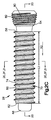
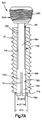
図2A〜2Dに示すように、スリーブ50は、第1方向X1に沿って近位端58から遠位端62まで延在する外面70を更に含む。外面70は、骨のような解剖学的構造と係合するように構成されたねじ山74を保持している。しかしながら、ねじ山74は所望の任意の解剖学的構造と係合するように構成され得ることを理解されたい。図2Cに示すように、ねじ山74は第1方向X1に沿ってスリーブ50の全長に延在することができる。しかしながら、ねじ山74は所望によりスリーブ50の長さに沿って部分的にのみ延在する場合があることを理解されたい。更に、ねじ山74が解剖学的構造と係合し、動的骨固定要素26を解剖学的構造に固着させることができる限りは、ねじ山74はスリーブ50の周囲に延在する複数のねじ山セグメントを備えることができることを理解されたい。
As shown in FIG. 2A-2D, the
図2Dに示すように、スリーブ50は、第1の即ち近位の当接面76、及び、第1当接面76と逆方向に面する第2の即ち遠位の当接面78を更に含む。第1及び第2当接面76及び78は、固定部材54の対応する当接面に当接するように構成され、それにより、第1方向X1に沿ったスリーブ50に対する固定部材54の移動を制限する。図のように、第1当接面76はスリーブ50の近位端58である場合があり、第2当接面78はスリーブ50の遠位端62である場合がある。したがって、第1及び第2当接面76及び78は、距離L2によって互いから離間配置され得る。しかしながら、スリーブ50のこの部分が第1当接面76の近位及び第2当接面78の遠位に延在して、当接面76及び78がスリーブ50の近位端及び遠位端ではなくなる場合があることを理解されたい。
As shown in FIG. 2D, the
図2C及び2Dに示すように、固定部材54はスリーブ50のチャネル66内に延在し、固定部材54がスリーブに対して移動可能なようにスリーブ50に緩く連結される。固定部材54は、ヘッド80と、ヘッド80から第2方向X2に沿って遠位に延在するシャフト84と、シャフト84から延在する当接部材88とを有する。図のように、当接部材88は、スリーブ50がヘッド80と当接部材88との間で捕捉されるようにシャフト84の遠位端から延在することができる。これによって、スリーブ50は固定部材54に連結される。第2方向X2は第1方向X1に平行であってもよく、あるいは第1方向X1から傾斜してオフセットしてもよいことを理解されたい。また、当接部材88がシャフト84の遠位端に対して近位のシャフトの一部分から延在してもよいことを理解されたい。
As shown in FIGS. 2C and 2D, the securing
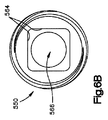
図2C及び2Dに示すように、ヘッド80は、円形断面のヘッド本体90を含み、近位面92、遠位面94及び側面96を画定しており、側面96は、側面96が近位面92から遠位面94まで延在するにつれて内方にテーパしている。テーパ側面96は、動的骨固定要素26が荷重キャリア22の骨固定穴38の1つを通じて挿入されるにつれて荷重キャリア22のねじ山42の1つと係合するように構成されたねじ山98を保持している。ねじ山98がねじ山42といったん係合すると、動的骨固定要素26は荷重キャリア22に固定される。図の実施形態ではヘッド80はねじ山98を含んでいるが、ヘッドにねじ山がなくてもよいことを理解されたい。更に、側面96は、側面96が近位面92から遠位面94まで延在するにつれて径方向に外方にテーパしてもよく、あるいは、側面96はテーパを含まなくてもよく、また近位面92及び遠位面94に対してほぼ垂直であってもよいことを理解されたい。
As shown in FIGS. 2C and 2D, the
図2Dに示すように、ヘッド80は、ヘッド80の近位面92内に延在する嵌合部材102を更に含む。嵌合部材102は、駆動器具の対応する嵌合部材と係合するように構成される。嵌合部材102は六角形の凹部106である場合があり、凹部106は、駆動器具が回転するにつれて、動的骨固定要素26が回転して解剖学的構造の中に打ち込まれるように、駆動器具の六角形の突出部によって係合されるように構成される。しかしながら、嵌合部材102は、嵌合部材102が駆動器具と嵌合することによって動的骨固定要素26に回転を与えることができる限りは、所望の他の構成を含むことができることを理解されたい。例えば、嵌合部材102はスロット形の凹部であってもよい。
As shown in FIG. 2D, the
図2Dに示すように、ヘッド80の遠位面94はシャフト84から径方向に外向きに延出して、第1当接面114を有するショルダ110を画定する。ショルダ110は、第2方向X2に対して垂直の方向に沿って測定される断面寸法D2を有する。ショルダ110の断面寸法D2は、チャネル66の断面寸法D1より大きい。図2Dに示すように、第1当接面114はスリーブ50の第1当接面76に面しており、第1方向X1に沿ったスリーブ50に対する固定部材54の遠位移動を制限するようにスリーブ50の第1当接面76に当接するように構成される。
As shown in FIG. 2D, the
例示の実施形態では、ヘッド80は骨プレートを解剖学的構造に固着させるように構成されているが、ヘッド80が他の荷重キャリアを解剖学的構造に固着させるためのその他の構成を有してもよいことを理解されたい。例えば、ヘッド80は脊椎ロッドを受容するチャネルを画定するように構成されてもよい。そのような実施形態では、チャネルは第2方向X2に対して垂直の方向に沿ってヘッドを通じて延在することができ、チャネルが第2方向X2に沿ってロッドを受容することができるように開口を有することができる。しかしながら、第2方向X2に対して垂直の方向に沿ってチャネルがロッドを受容することができるようにチャネルが開口を有してもよいことを理解されたい。
In the illustrated embodiment, the
図2Dに示すように、シャフト84はヘッド80の遠位面94から遠位方向に延在している。シャフト84は、スリーブ50の第1当接面と第2当接面との間の全長L2とほぼ同等以上の長さの全長L3を有することができる。したがって、シャフト84の近位端がチャネル66の近位端に対して近位になり、かつシャフト84の遠位端がチャネル66の遠位端に対して遠位になるように、スリーブ50のチャネル66を完全に貫通して延在するようにシャフト84を構成することができる。しかしながら、場合によってはシャフト84はスリーブ50の全長L2より短い全長L3を有することができることを理解されたい。例えば、いくつかの実施形態では、当接部材は、当接部材の一部分がスリーブ50のチャネル66の内部になるようにシャフトから延出することができる(例として図5Aを参照)。
As shown in FIG. 2D,
図2D及び2Eに示すように、シャフト84はチャネル66の内面64に面する外面120を少なくとも含む。図2Eに示すように、シャフト84は4つの外面120を含み、外面はそれぞれ、チャネル66の対応する内面64に面している。したがって、シャフト84は非円形の断面を有することができる。即ち、シャフト84の断面は、図のような正方形のような多角形である場合がある。しかしながら、シャフト84を任意の数の外面120によって画定することができ、また所望により、シャフト84の断面が任意の非円形を有することができることを理解されたい。例えば、シャフト84及びチャネル66の断面は、図2Hに示すように六角形であってもよい。更に、シャフト84の全長に沿ったシャフト84のそれぞれの部分の断面が非円形である場合があり、あるいは、シャフト84の長さの一部分のみに沿ってシャフト84の断面が非円形である一方で、シャフト84の長さの残りの部分が円形の断面を有する場合があることを理解されたい。シャフト84が非円形かつチャネル66が非円形であるために、スリーブ50は固定部材54が回転するにつれて回転する。即ち、固定部材54が回転するにつれて、シャフト84の外面120はスリーブ50の内面64と接触し、それによりスリーブ50を回転させて、解剖学的構造の中へと打ち込む。したがって、スリーブ50が固定部材54の回転につれて回転するためにスリーブ50を固定部材54に強固に連結する(即ち溶接する)必要はない。しかしながら、いくつかの実施形態では、シャフト84及びチャネル66が円形の断面を有する場合があることを理解されたい。例えば、シャフト84又はチャネル66は、固定部材54が回転するにつれてスリーブ50が回転するように互いに係合する機構を含んでもよい。
As shown in FIGS. 2D and 2E, the
図2D及び2Eに示すように、シャフト84の外面120のそれぞれは、対応する非ゼロの隙間130が外面120と内面64との間に画定されるように、対応するチャネル66の内面64と面する。図のように、少なくともチャネル66の内部にあるシャフト84の一部分は、チャネル66の断面寸法D1より小さい、第2方向X2に対して垂直の方向に沿って測定される断面寸法D3を有する。したがって、固定部材54は、固定部材54が少なくとも第1方向X1に対して横断方向の方向成分を有する方向に沿ってチャネル66の内部で移動可能なようにチャネル66に受容される。具体的には、固定部材は複数の方向に沿ってスリーブ50に対して移動可能であり、複数の方向の各方向は第1方向X1に横断方向の方向成分を有する。寸法D3がシャフト84の全長に関して同じである場合があり、あるいは、説明したように固定部材54がチャネル66の内部を移動することができる限りは、寸法D3がシャフト84の長さに沿って変化する場合があることを理解されたい。断面寸法D1及び断面寸法D3は好ましくは同一の方向に沿って測定されることもまた理解されたい。
As shown in FIGS. 2D and 2E, each of the
図2Fを参照し、別の実施形態では、スリーブ50は1つの平面においてスリーブに対する固定部材54の移動を制限するように構成される場合がある。図2Fに示すように、スリーブ50は2つの平行な第1表面64aと2つの平行な第2表面64bとを含むことができ、第2表面64bは第1表面64aより長く、第1表面64aと共にチャネル66aを画定する。したがって、チャネル66aの断面は長方形である。即ち、チャネル66aは、第1方向X1に対して垂直の方向に沿って第1表面64aの間で測定される第1断面寸法D5、並びに第1方向及び第1断面寸法D5が測定される方向の両方に対して垂直の方向に沿って第2表面64bの間で測定される第2断面寸法D6を有する。図のように、第2断面寸法D6は第1断面寸法D5より大きい。
Referring to FIG. 2F, in another embodiment, the
図2Fに示すように、チャネル66aの第1断面寸法D5は、シャフト84の断面寸法D3とほぼ同等であり、またチャネル66aの第2断面寸法D6はシャフト84の断面寸法D3より大きい。したがって、固定部材54は、第1方向X1に対して垂直の第1平面においてスリーブ50に対して移動可能であり、かつ第1方向X1及び第1平面の両方に対して垂直の第2平面においてスリーブ50に対して固定されている。
As shown in FIG. 2F, the first cross-sectional dimension D 5 of the
図2C及び2Dを再び参照すると、当接部材88は、シャフト84の遠位端から延出し、また円形断面を有し、かつ近位面162、遠位面164、及び近位面162から遠位面164まで延在する側面166を画定する、当接部材本体160を含む。図2Dに示すように、当接部材88の近位面162はシャフト84から径方向に外方に延出してショルダ170を画定しており、ショルダ170は、ヘッド80の第1当接面114と面する第2当接面174を有する。ショルダ170は、チャネル66の断面寸法D1より大きい、第2方向X2に対して垂直の方向に沿って測定される断面寸法D4を有する。第2当接面174はスリーブ50の第2当接面78と面しており、第1方向X1に沿った固定部材54の近位移動を制限するようにスリーブ50の第2当接面78に当接するように構成される。
Referring again to FIGS. 2C and 2D, the
図2Gに示すように、スリーブ50はヘッド80と当接部材88との間に捕捉される。図のように、スリーブ50全体などスリーブ50の少なくとも一部分は、固定部材54が第1方向X1に沿ってスリーブ50に対してほぼ固定されるようにヘッド80のショルダ110と当接部材88のショルダ170との間で捕捉され得る。スリーブ50はまた、固定部材54が第1方向X1に沿ってスリーブ50に対して移動可能なようにヘッド80のショルダ110と当接部材88のショルダ170との間で捕捉されてもよい。したがって、第1及び第2当接面114及び174は、スリーブ50の全長L1とほぼ同等又はそれ以上のいずれかである長さL4が第1当接面114と第2当接面174との間に画定されるように第2方向X2に沿って互いに離間配置することができる。長さL4が長さL1より長い場合、スリーブ50とヘッド80との間及び/又はスリーブ50と当接部材88との間の少なくとも一方に可変の大きさの隙間を画定することができ(例えば図5Aを参照)、それにより、第1方向X1に沿ったスリーブ50に対する固定部材54の移動を可能にする。
As shown in FIG. 2G, the
図2Gを参照すると、固定部材54は、ヘッド80が第3方向X3に沿って移動可能であり、かつ当接部材88が第4方向X4に沿って移動可能であるように、スリーブ50に連結される。第3方向X3及び第4方向X4の両方は、第1方向X1に対して垂直の方向成分を有する。また、固定部材54の近位端が第3方向X3に沿って移動可能であり、かつ固定部材の遠位端が第4方向X4に沿って移動可能であるように、固定部材54がスリーブ50と連結されるとも換言することができる。したがって、動的骨固定要素の構成によっては、固定部材54の各部分がスリーブ50に対して移動可能である場合がある。固定部材54が第1方向X1、第3方向X3、及び第4方向X4に沿ってスリーブ50に対して移動可能であるので、固定要素26は改善された応力分散を有し、かつ微動を可能にして、生成される骨の質を改善する。
Referring to FIG. 2G, as the fixing
第3方向X3と第4方向X4は、ほぼ同一方向である場合もあり、互いにほぼ反対方向である場合もある。例えば、第3方向X3と第4方向X4がほぼ同一方向であるとき、固定部材54は、シャフト84の近位部及び遠位部がチャネル66の同一の内面64の停止部67と接触するか、ないしは別の方法で停止部67によって制限されるように、スリーブ50に対して移動する。あるいは、第3方向X3及び第4方向X4が互いにほぼ反対方向であるとき、固定部材54は、シャフト84の近位部がチャネル66の第1内面64の近位の停止部67と接触するか、ないしは別の方法で近位の停止部67によって制限され、シャフト84の遠位部が、第1内面64に対向して面する第2内面64の遠位の停止部67と接触するか、ないしは別の方法で遠位の停止部67によって制限されるように、スリーブ50に対して移動する。しかしながら、シャフト84が撓み、ヘッド80が当接部材88に対して移動するように固定部材54が移動する場合があることを理解されたい。例えば、使用中、当接部材88は移動可能ではない場合があり、動的骨固定要素が固着された解剖学的構造によって制限される場合がある。そのような場合、シャフト84は撓むことができ、ヘッド80はスリーブ50及び当接部材88に対して移動することができる。
A third direction X 3 fourth direction X 4 are sometimes is almost the same direction, also be a substantially opposite directions. For example, when the third direction X 3 and the fourth direction X 4 are substantially the same direction, the fixing
第3方向X3及び第4方向X4が互いにほぼ反対方向であるとき、シャフト84が延在する方向(即ち第2方向X2)は、チャネル66の中心軸Cに対して角度をつけてオフセットすることができる。例えば、図2Gに示すように、固定部材54は、シャフト84が中心軸Cに対して角度
![]()
![]()
![]()
![]()
![]()
![]()
固定部材54はまた、ヘッド80の当接面とスリーブ50の第1当接面との間、及び当接部材88の当接面とスリーブ50の第2当接面との間に可変の隙間が画定されるように第1方向X1に沿ってスリーブ50に対して移動可能であってもよい。可変の角度の隙間はゼロ以上であってよい。したがって、固定部材54は、複数の方向に沿ってスリーブ50に対して移動可能であってよく、各方向は、第1方向X1に対して垂直又は平行のいずれかである方向成分を有する。
The fixing
ここで図2Hを参照すると、固定部材54は、中心軸Cの周囲でスリーブ50に対して回転することも可能である。固定部材54は時計回り又は反時計回りのいずれかで回転することができる。図のように、シャフト84及びチャネル66の両方が多角形の形状であるために、固定部材54の回転を制限することができる。即ち、固定部材54はスリーブ50に対して特定の角度の回転に制限され得る。例えば、例示されているように30度の回転に固定部材54を制限することができる。しかしながら、固定部材54及びスリーブ50は、所望によりスリーブ50に対して任意の角度で固定部材54が回転できるように構成することができることを理解されたい。したがって、固定部材54はスリーブ50に対して6度までの自由度を有することができる。
Referring now to FIG. 2H, the securing
図1を参照し、操作中、荷重キャリア22を第1骨部分と第2骨部分との間に画定された骨の隙間に渡して第1骨部分及び第2骨部分に固着させることができる。荷重キャリア22は、少なくとも1つの固定穴38が第1骨部分14aと整列し、少なくとも1つの固定穴38が第2骨部分14bと整列するように位置づけることができる。スリーブ50が第1骨部分14aと係合し、ヘッド80のねじ山が固定穴38のねじ山と係合するように、第1動的骨固定要素26aを固定穴38の1つを通じて挿入することができる。同様に、スリーブ50が第2骨部分14bと係合し、ヘッド80のねじ山が固定穴38のねじ山と係合するように、第2動的骨固定要素26bを固定穴38の1つを通じて挿入することができる。動的骨固定要素26を使用することにより、長手方向を含む複数の方向に沿った第1骨部分14a及び第2骨部分14bの微動が可能になり、第1骨部分14aと第2骨部分14bとの融合を促進する。第1骨部分14a及び第2骨部分14bは、下顎の骨部分又は頸椎の椎体である場合がある。しかしながら、第1骨部分14a及び第2骨部分14bは、体内に見出される任意の骨部分又は解剖学的構造である場合があることを理解されたい。
With reference to FIG. 1, during operation, the
ここで図3及び4を参照すると、様々な製造手法を用いて固定部材54をスリーブ50に連結することができる。いずれの場合も、固定部材54はスリーブ50に緩く連結する(即ち溶接しない)ことができる。即ち、固定部材54の全ての部分はスリーブ50に対して移動可能であり得る。例えば、固定部材54がスリーブ50に連結されたとき、固定部材54の近位端及び遠位端の両方が、第1方向X1に対して垂直の方向成分を有する方向に沿ってスリーブ50に対して移動可能であり得る。しかしながら、使用中、固定部材54の遠位部はスリーブ50に対して固定されている場合があることを理解されたい。
With reference now to FIGS. 3 and 4, the securing
図3に示すように、ヘッド80が、一体成形ないしは別の方法でモノリシックであるシャフト84及び当接部材88から別個であるように、固定部材54を最初に成形することができる。動的骨固定要素26を組み立てるために、シャフト84をチャネル66の遠位端に挿入し、当接面174がスリーブ50の第2当接面68に当接するまでチャネル66の近位端に向かって長手方向Lに沿って平行移動させることができる。いったん挿入したら、当接面114を有するヘッド80を溶接によりシャフト84の近位端に連結することにより、スリーブ50をヘッド80及び当接部材88のそれぞれの当接面114と174との間で捕捉することができる。しかしながら、シャフト84を第1当接面と一体形成し、第2当接面を後にシャフトに連結することができる限りは、動的骨固定要素26を他の方法で組み立ててもよいことを理解されたい。例えば、ヘッド80とシャフト84を一体形成する一方で、当接部材88を別個にすることができることを理解されたい。そのような場合、シャフト84をチャネル66の近位端を通じて挿入し、当接面114がスリーブ50の第1当接面76に当接するまでチャネル66の遠位端に向かって長手方向Lに沿って平行移動させることができる。いったん挿入したら、当接面174を有する当接部材88を溶接によりシャフト84の遠位端に連結することができる。また、溶接を用いずにヘッド80又は当接部材88をシャフト84に連結することができることも理解されたい。例えば、ヘッド80、シャフト84、及び/又は当接部材88に形成されているロッキング又はスナップ機構を用いてヘッド80又は当接部材88をシャフト84に連結することができる。
As shown in FIG. 3, the
図4に示すように、スリーブ50を固定部材54上にオーバーモールドすることもまた可能である。そのような場合、固定部材54はモノリシックないしは別の方法で単一の単位として一体成形することができ、スリーブ50をシャフト84上にオーバーモールドすることができる。即ち、ヘッド80とシャフト84と当接部材88とを互いに一体式にすることができ、成形型200を用いてスリーブ50をシャフト84上に重ねて成形することができる。図4に示すように、成形型200は上方ダイと下方ダイ204とを含むことができる。一方のダイがもう一方のダイに対して移動可能であってもよく、あるいは両方のダイが互いに対して移動可能であってもよい。特に記載がない限り、上方ダイと下方ダイは同一の構造を有することができ、したがって成形型は、上方ダイを反転して上方ダイを下方ダイ204と接合することによって形成することができる。結果的に、本明細書では下方ダイ204を詳細に説明するが、特に記載がない限り、下方ダイ204の説明は上方ダイにも該当することを理解されたい。
It is also possible to overmold the
下方ダイ204は、上方ダイの相補的係合面と係合するように構成された係合面212を画定する上面208を含む。下方ダイ204は、係合面212から垂直にダイ204内に延在しているポケット216を更に画定する。ポケット216はシャフト84を受容するように構成され、シャフト84の半分を取り巻くスリーブ50の前半部のような部分を画定する。図のように、ポケット216は、スリーブ50の外壁の形状に対応する形状を有する外壁218を有する。下方ダイ204のポケット216は、ダイが合体されたときに対応する成形型の窪みを形成するように上方ダイの相補的ポケットと組み合わせることができる。成形型の窪みは、シャフト84全体の周囲にスリーブ50を画定することができる。
Lower die 204 includes an
下方ダイ204は、ポケット216の外壁218を貫通する射出ポート238を画定する末端を画定するチャネル234を有する少なくとも1つの射出導管セクション230を更に含む。チャネル234は、成形材料を受容するように構成されており、上方ダイ及び下方ダイによって形成された窪みの中に成形材料を方向付ける。射出成形材料はシャフト及びポケットにぴったりと一致して、上述のスリーブ50を形成する。
The
シャフト84の外面とスリーブ50のチャネル66の内面との間に確実に隙間が形成されるように、充填材料220をシャフトとダイ204との間に配置することができる。例えば、充填材料220は、シャフト84上に配置されるワックスであってよく、ワックスはスリーブ50が形成された後に取り除くことができ、それにより、スリーブ50のチャネル66内で固定部材54が移動するのを可能にする。しかしながら、充填材料は他の構成を有してもよいことを理解されたい。例えば、充填材料は砂であってもよい。
固定要素26は所望の任意の手法を用いて製造することができることを理解されたい。例えば、スリーブ50は、選択的レーザー焼結のような3D金属印刷により固定部材54に形成するないしは別の方法で連結することもまた可能である。選択的レーザー焼結システムは、金属の小粒子を所望の3D形状(即ちスリーブ50の形状)を有する塊に融合するように構成された炭酸ガスレーザーのような強力なレーザーを含むことができる。したがって、スリーブ50を形成するために、スリーブ50の3D記述を含有するデジタルファイルをシステムにダウンロードするないしは別の方法で転送することができる。プロセスが始まる際に、粉末材料の薄い第1層をシステムの建造プラットホームの全体に散布することができる。次いで、3Dデジタル記述からのデータを用いて、レーザーは粉末材料の第1層の上にスリーブ50の断面を選択的に描出する。レーザーは断面を描出する際、粉末材料を選択的に焼結(加熱及び融合)することにより、スリーブ50の第1断面を示す固体塊を作成する。システムは、スリーブ50が完成するまでこのプロセスを続ける。
It should be understood that the
ここで図5A〜5Dを参照すると、成形型又は溶接を使用せずに動的骨固定要素26を手作業で組み立てることができるように固定部材を構築することができる。図5A〜5Dに示すように、動的骨固定要素326は、スリーブ350と、スリーブ350に緩く連結された固定部材354とを含む。スリーブ350及び固定部材354は、図2A〜2Eに示すスリーブ50及び固定部材54と同一であり、特に記載のない限り同様の構造を含む。更に、動的骨固定要素326は、特に記載のない限り動的骨固定要素26と同様のやり方で動作及び機能する。
Referring now to FIGS. 5A-5D, the fixation member can be constructed such that the dynamic
図5Aに示すように、スリーブ350は第1方向X1に沿って細長く、第1方向X1に沿って、第1端即ち近位端358、及び近位端358から離間配置された第2端即ち遠位端362を画定する。スリーブ350は、第1方向X1に沿って近位端358から遠位端362まで測定される全長L2を有することができる。スリーブ350は、チャネル366が近位端358及び遠位端362の両方を通じて延在するように第1方向X1に沿って近位端358から遠位端362に向かって延在するチャネル366を少なくとも部分的に画定する内面364を含む。図のように、チャネル366は、第1方向X1に対して垂直の方向に沿って測定される断面寸法D1を有する。チャネル366の寸法D1は、固定部材354が、第1方向X1に対して横断方向の方向成分を有する少なくとも一方向に沿ってチャネル366内を移動可能なように、固定部材354を受容することができる。
As shown in FIG. 5A, the
図のように、スリーブ350は、第1の即ち近位の当接面376及び、第1当接面376に背を向けている第2の即ち遠位の当接面378を更に含む。第1及び第2当接面376及び378は、固定部材354の対応する当接面に当接するように構成され、それにより第1方向X1に沿ったスリーブ350に対する固定部材354の移動を制限する。図のように、第1当接面376はスリーブ350の近位端358である場合があり、第2当接面378はスリーブ350の遠位端362である場合がある。したがって、第1及び第2の当接面376及び378は、第1方向X1に沿って長さL2によって互いから離間配置され得る。しかしながら、当接面376及び378がスリーブ350の絶対近位端及び絶対遠位端ではないように、スリーブ350の部分が第1当接面376に対して近位にかつ第2当接面378に対して遠位に延在してもよいことを理解されたい。
As shown, the
図5Aに示すように、固定部材354は第1方向X1に沿ってスリーブ350のチャネル366を通じて延在する。図5B及び5Cに示すように、固定部材354は、ヘッド380と、ヘッド380から第2方向X2に沿って遠位方向に延在するシャフト384と、シャフト384から延出する当接部材388とを有する。図のように、当接部材388は、当接部材388の少なくとも一部分が第2方向X2に対して垂直の方向に沿って延在し、スリーブ350がヘッド380と当接部材388との間で捕捉されるように、シャフト384の遠位端から延出することができる。これによって、スリーブ350は固定部材354に連結可能となる。
As shown in FIG. 5A, the fixing
図5B及び5Cに示すように、ヘッド380は、円形断面のヘッド本体390を含み、近位面392、遠位面394及び側面396を画定しており、側面396は、側面396が近位面392から遠位面394まで延在するにつれて内方にテーパしている。テーパ側面396は、動的骨固定要素326が荷重キャリア22の骨固定穴38の1つを通じて挿入されるにつれて荷重キャリア22のねじ山42の1つと係合するように構成されたねじ山398を保持している。ねじ山398がねじ山42といったん係合すると、動的骨固定要素326は荷重キャリア22に固定される。
As shown in FIGS. 5B and 5C, the
図5A及び5Cに示すように、ヘッド380の遠位面394はシャフト384から径方向に外方に延出して、第1当接面414を有するショルダ410を画定している。ショルダ410は、第2方向X2に対して垂直の方向に沿って測定される断面寸法D2を有する。ショルダ410の断面寸法D2は、チャネル366の断面寸法D1より大きい。図5Aに示すように、第1当接面414はスリーブ350の第1当接面376に面しており、第1方向X1に沿った固定部材354の遠位移動を制限するようにスリーブ350の第1当接面376に当接するように構成されている。
As shown in FIGS. 5A and 5C, the
図5Cに示すように、シャフト384はヘッド380の遠位面394から遠位方向に延在している。シャフト384はチャネル366の内面364に面する外面420を少なくとも1つ含む。動的骨固定要素26と同様に、固定部材354及びスリーブ350は、固定部材354が回転するにつれてシャフト384の外面420がスリーブ350の内面364と接触し、それによりスリーブ350を回転させて、解剖学的構造の中に打ち込むように構成される。したがって、スリーブ350を固定部材354に強固に接続する(溶接する)必要はない。
As shown in FIG. 5C, the
図5Aに示すように、シャフト384の各外面420は、対応する非ゼロの隙間430が外面420と内面364との間に画定されるように、チャネル366の対応する内面364と面する。したがって、少なくともチャネル366の内部にあるシャフト384の一部分は、チャネル366の断面寸法D1より小さい、第2方向X2に対して垂直の方向に沿って測定される断面寸法D3を有する。したがって、固定部材354は、固定部材354が少なくとも第1方向X1に対して横断方向の方向成分を有する方向に沿ってチャネル366の内部で移動可能なようにチャネル366に受容される。具体的には、固定部材354は複数の方向に沿ってスリーブ350に対して移動可能であり、それらの複数の方向の各方向は、第1方向X1に対して横断方向の方向成分を有する。寸法D3がシャフト384の全長に関して同じである場合があり、あるいは、説明したように固定部材354がチャネル366の内部を移動することができる限りは、寸法D3がシャフト384の長さに沿って変化し得ることを理解されたい。
As shown in FIG. 5A, each
図5A〜5Dに示すように、当接部材388はシャフト384の遠位端から延出しており、かつ少なくとも1つの、例えば4つの可とう性の延長部460を含み、それらの延長部は細長いスロット461によって互いから分離されており、かつ動的骨固定要素326の組み立て中にシャフト384がチャネル366を通過する際に弾力的に内方に撓むように構成される。それぞれの可とう性の延長部460は、細長い本体462と棚464を含み、棚464は、第2方向に対して垂直の方向に沿って本体462の遠位部から径方向に外方に延在する。棚464は共に、ヘッド380の第1当接面414に面する第2当接面474を有するショルダ470を画定する。当接部材388又は少なくともショルダ470は、チャネル366の断面寸法D1より大きい、第2方向X2に対して垂直の方向に沿って測定される断面寸法D4を有する。第2当接面474はスリーブ350の第2当接面378と面しており、第1方向X1に沿った固定部材354の近位移動を制限するようにスリーブ350の第2当接面378に当接するように構成される。
As shown in FIGS. 5A-5D,
図5Cに示すように、各棚464は、棚464の近位面から棚464の遠位面まで内方にテーパする外面468を更に含む。各テーパ表面468は、チャネル366の内面364と係合し、それにより、シャフト384がチャネル366を通過する際に可とう性の延長部460を内方に押し込むように構成される。しかしながら、外面468はテーパされなくてもよく、所望により他の構成を有することができることを理解されたい。例えば、外面468は、棚464の近位面に対して垂直であってもよい。
As shown in FIG. 5C, each
図5Aに示すように、例えばスリーブ350の全体など少なくとも一部分は、スリーブ350のその部分が第1方向に沿って当接部材388の当接面474と整合するように、ヘッド380のショルダ410と当接部材388のショルダ470との間で捕捉される。図のように、スリーブ350は、固定部材354が第1方向X1に沿ってスリーブ350に対して移動可能なようにヘッド380のショルダ410と当接部材388のショルダ470との間に捕捉されてもよく、あるいは、スリーブ350は第1方向X1に沿ってスリーブ350に対して固定部材354が実質的に固定されるようにヘッド380のショルダ410と当接部材388のショルダ470との間に捕捉されてもよい。したがって、第1及び第2当接面414及び474は、スリーブ350の第1当接面376と第2当接面378との間の全長L2とほぼ同等又はそれ以上のいずれかである長さLC3が第1当接面414と第2当接面474との間に画定されるように、第2方向X2に沿って互いに離間配置することができる。
As shown in FIG. 5A, at least a portion, such as the
図5Aに示すように、長さLC3が長さL2より長い場合、スリーブ350とヘッド380との間及び/又はスリーブ350と当接部材388との間の少なくとも一方に、可変の大きさの隙間480を画定することができる。具体的には、ヘッド380の当接面とスリーブ350の第1当接面376との間、及び/又は当接部材388の当接面とスリーブ350の第2当接面378との間に、可変の大きさの隙間480を画定することができる。可変の大きさの隙間480は、第1方向X1に平行の方向に沿って測定することができ、約0mm〜約0.4mmの間で変化することができる。しかしながら、可変の大きさの隙間480は任意の所望の距離の間で変化できることを理解されたい。更に、ヘッド380とスリーブ350との間の隙間480が減少すると当接部材388とスリーブ350との間の隙間480が増大し、その逆もまた然りであることも理解されたい。
As shown in FIG. 5A, when the length L C3 is longer than the length L 2 , the length L C3 is variable between at least one of the
棚464のテーパ面468がチャネルの内面364と接触し、それにより可とう性の延長部を第1位置から撓んだ第2位置に撓ませるないしは別の方法で内方に押し込むように、当接部材388をチャネル366の近位端に挿入することによって固定部材354をスリーブ350に連結する。可とう性の延長部460は、シャフト384がチャネル366を通過する際も撓んだ状態のままである。棚464がチャネル366を通過し、スリーブ350に対して遠位になった後は、可とう性の延長部460は第1位置に戻り、又は少なくとも第1位置の実質的に近くに戻り、第1当接面414と第2当接面474との間にスリーブ350を捕捉する。したがって、当接部材388は、当接部材388がチャネル366内にあるときに第2方向に沿って第1断面寸法を有する外面を画定することができ、この外面は、当接部材388がチャネル366に対して遠位であるときに第1断面寸法より大きい第2方向に沿った第2断面寸法を画定することができる。したがって、当接部材388は、外面がチャネル366にあるとき圧縮され、チャネル366に対して遠位であるとき拡張するように弾力的である。
The
ここで図6A〜6Dを参照すると、別の実施形態にしたがって構築されたスリーブ550は、固定部材354のような固定部材に緩く連結されるように構成することができる。図6Aに示すように、スリーブ550は第1方向X1に沿って細長く、第1端即ち近位端558及び第1方向X1に沿って近位端558から離間配置された第2端即ち遠位端562を画定する。スリーブ550は、第1方向X1に沿って近位端558から遠位端562まで測定される全長L2を有することができる。スリーブ550は、近位端558から第1方向X1に沿って遠位端562に向かって延在するチャネル565を含む。具体的には、スリーブ550は、チャネル565の第1部分566を少なくとも部分的に画定する第1内面564と、第1部分566の遠位端から第1方向X1に沿って遠位端562に向かって延在するチャネル565の第2部分570を少なくとも部分的に画定する第2内面568とを含む。したがって、チャネル565は第1部分566と第2部分570とを含むと言うことができる。図のように、チャネル565の第1部分566は、第1方向X1に対して垂直の方向に沿って測定される断面寸法D7を有し、チャネル565の第2部分570は、同じく第1方向X1に対して垂直の方向に沿って測定される、チャネル565の第1部分566の断面寸法より大きい第2断面寸法D8を有する。
6A-6D, a
チャネル565の第1部分566は第1方向X1に沿って長さLC1を有し、チャネル565の第2部分570は第1方向に沿って第2の長さLC2を有する。第1部分566の長さLC1及び寸法D7は、固定部材354が、第1方向X1に対して横断方向の方向成分を有する少なくとも一方向に沿ってチャネル566内を移動可能なように、チャネル565が固定部材354を受容することができるように構成される。チャネル565の第2部分570の寸法D8は、第2部分570が固定部材354の棚464を受容して固定部材354をスリーブ550に連結することができるように構成される。寸法D8は、第1方向X1に対して垂直の方向に沿って固定部材354の遠位端が移動することを可能にするように十分に大きくてよい。
The
図6Bに示すように、スリーブ550は第1部分566を画定する4つの表面564含む。したがって、第1部分566の断面は非円形である。即ち、第1部分566の断面は、図のような正方形のような多角形である場合がある。しかしながら、所望により第1部分566を任意の数の内面564によって画定することができ、かつ第1部分566の断面が任意の非円形を有することができることを理解されたい。例えば、第1部分566の断面は六角形であってもよい。更に、第1部分566の全長に沿って第1部分566のそれぞれの部分の断面が非円形であってもよく、あるいは、第1部分566の長さの一部分のみに沿って第1部分566の断面が非円形である一方で、第1部分566の長さの残りの部分が円形の断面を有してもよいことを理解されたい。
As shown in FIG. 6B, the
棚464は、固定部材354が第1方向において固定されるように第2部分570によって受容されてもよく、あるいは、棚464は、固定部材354が第1方向に沿ってチャネル565の内部で移動可能なように第2部分570によって受容されてもよい。例えば、スリーブ550は、固定部材354の対応する当接面と当接するように構成された第1即ち近位の当接面576及び第2即ち遠位の当接面578を更に含み、それにより、第1方向X1に沿ってスリーブ550に対して固定部材354が移動することを制限する。図のように、第1当接面376は第2部分570の近位端358である場合があり、第2当接面378は第2部分570の遠位端362である場合がある。即ち、第1及び第2の当接面576及び578は、少なくとも部分的に第2部分570を画定し、第1方向に沿って互いに対向することができる。したがって、第1及び第2の当接面376及び378は、第1方向X1に沿って第2の長さLC2によって互いから離間配置され得る。当接部材388の棚464は、第1方向X1に沿って第2の長さLC2より短い長さLMを有することによって、第1方向X1に沿って固定部材354が移動するのを可能にすることができる。
The
図6Cに示すように、スリーブ550は、第1方向X1に沿って近位端558から遠位端562まで延在する外面580を更に含む。外面580は、骨のような解剖学的構造と係合するように構成されたねじ山582を保持している。しかしながら、ねじ山582は所望の任意の解剖学的構造と係合するように構成され得ることを理解されたい。図6Cに示すように、ねじ山582は第1方向X1に沿ってスリーブ550の全長に延在することができる。しかしながら、ねじ山582は所望によりスリーブ550の長さに沿って部分的にのみ延在してもよいことを理解されたい。更に、ねじ山582が解剖学的構造と係合し、かつ動的骨固定要素を解剖学的構造に固着させることができる限りは、ねじ山582がスリーブ550の周囲に延在する複数のねじ山セグメントを備えてもよいことを理解されたい。
As shown in FIG. 6C, the
図6Cに示すように、スリーブは、遠位端562に近接した切断フルート586を更に含むことができる。したがって、固定要素が回転するにつれて切断フルート586が解剖学的構造を切り込み、それにより、スリーブ550を解剖学的構造の中に進める。
As shown in FIG. 6C, the sleeve can further include a cutting
棚464のテーパ面468がチャネル365の第1部分566の内面564と接触し、それにより可とう性の延長部を第1位置から撓んだ第2位置に弾力的に内方に撓ませるないしは別の方法で押し込むように、当接部材388をチャネル565の近位端に挿入することによって固定部材354をスリーブ550に連結することができる。可とう性の延長部460は、シャフト384が第1部分566を通過する際も撓んだ状態のままである。棚464が第1部分566を通じて第2部分570の中に入った後は、可とう性の延長部460は第1位置に戻り、又は少なくとも第1位置に実質的に近くになり、少なくとも第1当接面474とヘッド380との間にスリーブ550を捕捉する。固定部材354は、第2部分570の長さLC2、シャフト384の長さ、及び棚464の長さLMに依存して第1方向に沿って移動するように構成することができる。
The
当接面576及び578は、第1方向に沿って固定部材354の移動を制限するように構成することができる。しかしながら、いくつかの実施形態ではスリーブ550の近位端が当接面を画定する場合があることを理解されたい。そのような実施形態では、スリーブ550の近位端及び近位当接面576は、第1方向に沿って固定部材354の移動を制限するように構成される。したがって、スリーブ550の少なくとも一部分は、第1方向X1に沿って、当接部材388の当接面474とヘッド380との間で捕捉されると言うことができる。スリーブ550の捕捉された部分が第1の長さ(即ち第1部分566の長さLC1)を画定し、固定部材354がヘッド380と当接部材388の当接面474との間に第1の長さより長い第2の長さ(即ちLC3)を画定する実施形態においては、固定部材は第1方向X1に沿って移動可能であり得る。
The contact surfaces 576 and 578 can be configured to limit movement of the fixing
図7Aを参照すると、別の実施形態では、動的固定要素626は、スリーブ50と、遠位端が固定されている一方で固定部材654の近位端がスリーブ50に対して移動可能なようにスリーブに連結された固定部材654とを含むことができる。固定部材654は、図5A〜5Dに示す固定部材354と同一であり、特に記載のない限り、同様の構造を含む。更に、動的骨固定要素626は、特に記載のない限り、動的骨固定要素326と同様のやり方で動作及び機能する。
With reference to FIG. 7A, in another embodiment, the
図7Aに示すように、固定部材654は第1方向X1に沿ってスリーブ50のチャネル66を通じて延在しており、ヘッド680と、第2方向X2に沿ってヘッド680から遠位に延在するシャフト684と、シャフト684から延出している当接部材688とを含む。図のように、当接部材688は、当接部材688の少なくとも一部分が第2方向X2に対して垂直の方向に沿って延在し、スリーブ50がヘッド680と当接部材688との間で捕捉されるように、シャフト684の遠位端から延出することができる。これによって、スリーブ50は固定部材654に連結可能となる。
As shown in FIG. 7A, the fixing
シャフト684はヘッド680から遠位に延在する。シャフト684はチャネル66の内面64に面する外面720を少なくとも1つ含む。図7Aに示すように、シャフト684の外面720は、対応する非ゼロの隙間730が外面720と内面64との間に画定されるようにチャネル66の対応する内面64と面する。したがって、少なくともチャネル66の内部にあるシャフト684の一部分は、チャネル66の断面寸法D1より小さい、第2方向X2に対して垂直の方向に沿って測定される断面寸法D9を有する。したがって、固定部材654は、ヘッド680が少なくとも第1方向X1に対して横断方向の方向成分を有する方向に沿ってスリーブ50に対して移動可能なようにチャネル66に受容される。具体的には、ヘッド680は複数の方向に沿ってスリーブ50に対して移動可能であり、複数の方向の各方向は第1方向X1に横断方向の方向成分を有する。しかしながら、寸法D9はシャフト684の全長に関して同じであってもよく、あるいは、説明したようにヘッド680がスリーブ50に対して移動することができる限りは、寸法D9はシャフト684の長さに沿って変化してもよいことを理解されたい。
当接部材688はシャフト684の遠位端から延出しており、少なくとも1つの、例えば4つの可とう性の延長部760を含み、それらの延長部は細長いスロット761によって互いから分離されており、動的骨固定要素626の組み立て中にシャフト684がチャネル66を通過する際に弾力的に内方に撓むように構成される。それぞれの可とう性の延長部760は、細長い本体762と棚764とを含み、棚764は、第2方向に対して垂直の方向に沿って本体762の遠位部から径方向に外方に延在する。棚764は共に、チャネル66の断面寸法D1より大きい、第2方向X2に対して垂直の方向に沿って測定される断面寸法D10を有するショルダ770を画定する。したがって、当接部材688は、スリーブ50に対して第1方向に沿って固定部材654の移動を制限するように構成される。
The
引き続き図7Aを参照し、チャネル66内の当接部材688の一部分790は、チャネル66の断面寸法D1とほぼ同等の断面寸法D11を有する。したがって、当接部材688は、第1方向X1に対して垂直の方向に沿ってスリーブ50に対して固定することができる。したがって、固定部材654の近位端がスリーブ50に対して移動可能である一方で、固定部材654の遠位端をスリーブに対して固定することができると言うことができる。
With continued reference to FIG. 7A, a
ここで図7B〜7Dを参照すると、別の実施形態にしたがって、動的固定要素826はスリーブ850と、スリーブ850に連結された固定部材854とを含むことができ、固定部材854の一部分は円筒形の断面であり、もう一方の部分は多角形の断面である。図7Bに示すように、特に記載のない限り、固定部材854は、図5A〜5Dに示す固定部材354がスリーブに連結されているのと同様のやり方でスリーブ850に連結されており、同様の構造体を含む。
Referring now to FIGS. 7B-7D, according to another embodiment, the
図7Bに示すように、スリーブ850は、近位チャネル部分分866a及び遠位チャネル部分866bを含むチャネル866を画定する。近位チャネル部分866aは断面寸法D12を画定することができ、遠位チャネル部分866bは、近位チャネル部分866bのそれより小さい断面寸法D13を画定することができる。図7C及び7Dに示すように、近位チャネル部分866aは断面が円形である場合があり、遠位チャネル部分866bは断面が多角形(例えば、正方形、六角形等)である場合がある。しかしながら、近位チャネル部分866a及び遠位チャネル部分866bは所望の任意の形状及び寸法を有することができることを理解されたい。
As shown in FIG. 7B, the
図7B〜7Dを引き続き参照し、固定部材854は第1方向X1に沿ってスリーブ850のチャネル866を通じて延在しており、ヘッド880と、第2方向X2に沿ってヘッド880から遠位に延在するシャフト884と、シャフト884から延出している当接部材888とを含む。図のように、当接部材888は、当接部材888の少なくとも一部分が第2方向X2に対して垂直の方向に沿って延在し、スリーブ850がヘッド880と当接部材888との間で捕捉されるように、シャフト884の遠位端から延出することができる。これによって、スリーブ850は、固定部材854に連結可能である、ないしは別の方法で固定部材854によって捕獲される。
With continuing reference to FIG. 7b to 7d, the fixing
図7Bに示すように、シャフト884はヘッド880から遠位に延在し、当接部材888はシャフト884から遠位に延在する。図7Bに示すように、シャフト884は断面D14を画定することができ、チャネル866内の当接部材888の一部分はシャフト884の断面寸法より小さい断面寸法D15を画定することができる。図7C及び7Dに示すように、シャフト884は円形の断面である場合があり、遠位チャネル部分866b内の当接部材888の一部分の断面は多角形(例えば、正方形、六角形等)である場合がある。更に、シャフト884の外面と、近位チャネル部分866aを画定するスリーブ850の内面との間に隙間930が形成されるように、シャフト884の寸法D14は近位チャネル部分866aの寸法D12より小さい場合がある。同様に、当接部材888の外面と、遠位チャネル部分866bを画定するスリーブ850の内面との間に隙間930が形成されるように、寸法D13は寸法D15より小さい場合がある。したがって、第1方向X1に対して横断方向の方向成分を有する全ての方向に沿ってスリーブ850に対してヘッド880が移動可能で、かつ固定部材854の回転が固定部材854に合わせたスリーブ850の回転を引き起こすように、チャネル866は固定部材854を受容することができる。
As shown in FIG. 7B,
ここで図8A及び8Bを参照すると、動的固定要素926は複数の可とう性の脚部958を画定するスリーブ950と、スリーブ950に連結された固定部材54のような固定部材とを含むことができる。図8A及び8Bに示すように、固定部材54は図2A〜2Eに示す固定部材と同一であってよく、スリーブ950は、固定部材がスリーブ950のチャネル966を通過する際に可とう性の脚部958が外方に撓んで、当接部材がスリーブ950のチャネル966を通過することを可能にするように構成することができる。しかしながら、所望により固定部材は任意の構成を有することができることを理解されたい。例えば、固定部材は、図5A〜5Dに示す固定部材354と同様のものであってよい。
Referring now to FIGS. 8A and 8B, the
図8A及び8Bに示すように、スリーブ950は、第1方向に沿って細長い本体952と、第1方向に沿って本体952を貫通するチャネル966とを含む。本体952の遠位端は、可とう性の脚部958を画定する複数の切り抜き953を含む。可とう性の脚部958は、固定部材954がチャネル966を通過する際に、固定部材54の当接部材88がチャネル966を通過するまで可とう性の脚部958が外方に撓むように弾性的に可とう性である。図8Aに示すように、チャネル966は、近位チャネル部分966aと遠位チャネル部分966bとを有することができる。近位チャネル部分966aは、遠位チャネル部分966bの断面寸法より大きい断面寸法を有することができる。例えば、近位チャネル部分966aは、当接部材88が近位チャネル部分966aを通過することができるように、当接部材88の断面寸法D4以上の大きさの断面寸法を有することができる。
As shown in FIGS. 8A and 8B, the
当接部材88が遠位チャネル部分966bを通過する際に当接部材88が可とう性の脚部958を外方に撓ませて、当接部材88が遠位チャネル部分966bを通過することを可能にするように、近位部966bの断面寸法は当接部材88の断面寸法D4より小さい場合がある。
As the
引き続き図8Aを参照すると、スリーブ950は、近位チャネル部分966aが遠位チャネル部分966bに移行する傾斜部980を画定することができる。固定部材54がチャネル966を通過する際、当接部材88は傾斜部980に乗り、それにより可とう性の脚部958を外方に撓ませる。当接部材88がチャネル966を完全に通過すると、可とう性の脚部958はそれらの初期位置に実質的に戻り、スリーブ950を固定部材54の当接部材88とヘッド80との間に捕獲する。
With continued reference to FIG. 8A, the
ここで図9A〜9Eを参照すると、骨固定システム1010は、骨プレート1022として構成された荷重キャリアと、移植片1024を形成するために骨プレート1022に予め組み立てられたないしは別の方法で予め連結された固定部材1054と、対応する固定部材1054を受容することができる対応するスリーブ1050とを含むことができる。固定部材1054を骨プレート1022の対応する穴を通じて挿入することによって固定部材1054を骨プレート1022に予め連結することにより、図9Aに示すように移植片1024を形成してもよく、あるいは、図9Bに示すように、骨プレート1022と固定部材1054を一体形成して、モノリシックの移植片1054を形成するように、骨プレート1022と固定部材1054を予め連結してもよい。
Referring now to FIGS. 9A-9E, the
図9Cに示すように、スリーブ1050はその近位端に嵌合機構1052を含むことができる。ないしは別の方法で、前述のスリーブのいずれかを用いてスリーブ1050を構成する。嵌合機構1052は、ねじ回しの回転がスリーブ1050を解剖学的構造の中に打ち込むようにねじ回しを受容するように構成されたスロットである場合がある。しかしながら、各スリーブ1050は、図9Dに示すようにドライバー1078の回転がスリーブ1050の回転を引き起こすようにドライバー1078のドライバー嵌合インターフェイス1077を受容する形状を有するチャネル1066を画定することができることを理解されたい。例えば、チャネル1066及びドライバーの嵌合インターフェイス1077の両方が、例えば正方形又は六角形のような多角形の断面であってもよい。
As shown in FIG. 9C, the
操作中、解剖学的構造内に穴を形成することができるように、骨プレート1022によって接合されることになる解剖学的構造に対してドリルガイドを配置することができる。いったん形成したら、ドリルで開けた穴の中にスリーブ1050を打ち込む、ないしは別の方法で配置することができる。次いで、予め組み立てられた、ないしは別の方法で予め連結された移植片をスリーブ1050に連結することができる。即ち、図9Eに示すように、骨プレート1020に予め連結された固定部材1054をスリーブ1050にスナップ式に嵌合するか、ないしは別の方法で嵌合することができる。
During operation, a drill guide can be placed against the anatomy that is to be joined by the
ここで図10を参照すると、骨固定システム1110は、脊椎固定システムとして構成することができ、例えば対応する椎弓根又は所望により椎体の任意の他の部分のような複数の椎体Vに連結することができる脊椎ロッド1122として構成された荷重キャリアを含むことができる。システム1110は、移植片1124を形成するために脊椎ロッド1122と予め組み立てられた、ないしは別の方法で予め連結された複数の固定部材1154と、対応する固定部材1154を受容することができる対応するスリーブ1150とを更に含むことができる。固定部材1154は、固定部材1154を脊椎ロッド1122に手作業で組み立てることによって脊椎ロッド1122に予め連結してもよく、あるいは、脊椎ロッド1122と固定部材1154を一体形成してモノリシックの移植片1124を成形するように脊椎ロッド1122と固定部材1154を予め連結してもよい。固定システム1110の特徴は、所望により任意の脊椎固定システムに組み込むことができることを理解されたい。例えば、固定システム1110の特徴は、参照により本明細書に内容が組み込まれる米国特許公開番号第2011/0106166号に示されている脊椎固定システムに組み込むことができる。
Referring now to FIG. 10, the
操作中、脊椎ロッド1122によって接合される椎体Vに対してドリルガイドを配置して、椎体に穴を形成することができる。いったん形成したら、ドリルで開けた穴の中にスリーブ1150を打ち込む、ないしは別の方法で配置することができる。次いで、予め組み立てられた、ないしは別の方法で予め連結された移植片をスリーブ1150に連結することができる。即ち、図10に示すように、脊椎ロッド1120に予め連結された固定部材1154をスリーブ1150にスナップ式に嵌合するか、ないしは別の方法で嵌合することができる。
During operation, a drill guide can be placed against the vertebral body V joined by the spinal rod 1122 to form a hole in the vertebral body. Once formed, the
固定要素は様々な長さを有するように構成することができ、したがって、様々な最大隙間から変化するヘッドとスリーブとの間の可変の隙間を有するように構成することができる。例えば、頭蓋骨又は頭蓋の上顎領域に取り付けられるように構成された本明細書に記載の固定要素は、最大隙間が約0.15mm〜約0.4mmの範囲であるように構成することができる。即ち、全長1mmを有する固定要素は、約0.5mmのチャネル長さ、約0.35mmのシャフト長さ、及び0.15mmのヘッドとスリーブとの間の最大隙間を有することができ、全長2.7mmを有する固定要素は、約2.0mmのチャネル長さ、約1.6mmのシャフト長さ、及び0.2mmのヘッドとスリーブとの間の最大隙間を有することができ、全長約5.0mmを有する固定要素は、約3.2mmのチャネル長さ、約2.6mmのシャフト長さ、及び0.4mmのヘッドとスリーブとの間の最大隙間を有することができる。したがって、固定要素は5.0mmより短い全長を有することができると言うことができる。しかしながら、列挙した寸法は例示目的に過ぎず、説明した固定要素は所望により任意の寸法を有することができる。 The fixation element can be configured to have various lengths, and thus can be configured to have a variable clearance between the head and the sleeve that varies from various maximum clearances. For example, a fixation element described herein configured to be attached to the skull or the upper jaw region of the skull can be configured such that the maximum clearance ranges from about 0.15 mm to about 0.4 mm. That is, a fixing element having a total length of 1 mm can have a channel length of about 0.5 mm, a shaft length of about 0.35 mm, and a maximum clearance between the head and sleeve of 0.15 mm, The anchoring element having a .7 mm can have a channel length of about 2.0 mm, a shaft length of about 1.6 mm, and a maximum gap between the head and sleeve of 0.2 mm, for a total length of about 5. A securing element having 0 mm can have a channel length of about 3.2 mm, a shaft length of about 2.6 mm, and a maximum clearance between the head and sleeve of 0.4 mm. It can therefore be said that the fixing element can have a total length shorter than 5.0 mm. However, the listed dimensions are for illustrative purposes only, and the described securing elements can have any dimensions as desired.
当業者は、広い発明概念から逸脱することなく前述の実施形態に変更を行うことができることを理解されたい。更に、本明細書に記載した実施形態のうちのどれかに関して以上説明したような構造、特徴及び方法は、特に断らない限り、本明細書に記載にした他の実施形態のいずれかに組み込むことができることを理解されたい。例えば、動的骨固定要素26は、スリーブ50とヘッド80との間又はスリーブ50と当接部材88との間の少なくとも一方に隙間480が画定されるように構築することができ、あるいは、スリーブのチャネルのいずれかが完全に円筒形であってもよい。動的骨固定要素26及び326は所望により任意の手法を用いて製造することができ、本明細書に記載のものに限定されないことを更に理解されたい。したがって、本発明が、開示された特定の実施形態に限定されず、本開示の趣旨及び範囲内の修正を含むものであることを理解されたい。
It should be understood by those skilled in the art that changes can be made to the above-described embodiments without departing from the broad inventive concept. Moreover, structures, features, and methods as described above for any of the embodiments described herein are incorporated into any of the other embodiments described herein unless otherwise indicated. Please understand that you can. For example, the dynamic
〔実施の態様〕
(1) 荷重キャリアを骨に連結するように構成された動的骨固定要素であって、
第1方向に沿って細長いスリーブであって、前記スリーブは、近位端、前記第1方向に沿って前記近位端から離間配置されている遠位端、及び前記第1方向に沿って前記近位端を通じて前記遠位端に向かって延在しているチャネルを画定し、前記チャネルは、前記第1方向に対して垂直の方向に沿って測定される第1断面寸法を有し、前記スリーブは、骨と係合するように構成された外面を更に画定する、スリーブと、
固定部材であって、ヘッド、前記ヘッドから第2方向に沿って延在するシャフト、及び前記シャフトから延在する当接部材を有し、前記当接部材の少なくとも一部分は前記ヘッドに面しており、前記シャフトは、前記スリーブの少なくとも一部分が前記当接部材と前記ヘッドとの間に捕捉されることにより前記固定部材を前記スリーブと連結するように前記チャネル内に延出するように構成される、固定部材と、を備え、
前記チャネル内に存在するように構成された前記シャフトの少なくとも一部分は、前記第2方向に対して垂直の方向に沿って第2断面寸法を有し、前記第2断面寸法は、前記第1方向に対して横断方向の方向成分を有する方向に沿って前記固定部材が前記スリーブに対して移動可能なように前記第1断面寸法より小さい、動的骨固定要素。
(2) 前記固定部材が前記スリーブに連結されたときに、(i)前記スリーブと前記ヘッドとの間及び(ii)前記スリーブと前記当接部材との間の少なくとも一方に隙間が画定される、実施態様1に記載の動的固定要素。
(3) 前記ヘッドがショルダを画定し、前記固定部材が前記第1方向に沿って前記スリーブに対して移動可能なように前記スリーブ全体が前記当接部材と前記ショルダとの間に捕捉されるように構成される、実施態様1〜2のいずれかに記載の動的骨固定要素。
(4) 前記固定部材が前記スリーブに連結されたときに前記固定部材が複数の方向に沿って前記スリーブに対して移動可能であり、前記複数の方向の各方向が前記第1方向に対して横断方向の方向成分を有する、実施態様1〜3のいずれかに記載の動的骨固定要素。
(5) 前記固定部材が前記スリーブに連結されたときに前記固定部材の回転により前記スリーブを回転させるように、前記チャネルの断面が非円形であり、前記シャフトの断面が非円形である、実施態様1〜6のいずれかに記載の動的骨固定要素。
Embodiment
(1) a dynamic bone anchoring element configured to couple a load carrier to bone,
An elongate sleeve along a first direction, the sleeve being a proximal end, a distal end spaced apart from the proximal end along the first direction, and the sleeve along the first direction; Defining a channel extending through the proximal end toward the distal end, the channel having a first cross-sectional dimension measured along a direction perpendicular to the first direction; The sleeve further defines an outer surface configured to engage the bone; and
A fixing member having a head, a shaft extending from the head in a second direction, and a contact member extending from the shaft, wherein at least a portion of the contact member faces the head; And the shaft is configured to extend into the channel to couple the securing member to the sleeve by capturing at least a portion of the sleeve between the abutment member and the head. A fixing member,
At least a portion of the shaft configured to be in the channel has a second cross-sectional dimension along a direction perpendicular to the second direction, the second cross-sectional dimension being in the first direction. A dynamic bone anchoring element that is smaller than the first cross-sectional dimension so that the anchoring member is movable relative to the sleeve along a direction having a transverse directional component.
(2) When the fixing member is connected to the sleeve, a gap is defined at least one of (i) between the sleeve and the head and (ii) between the sleeve and the contact member. 2. A dynamic anchoring element according to
(3) The entire sleeve is captured between the contact member and the shoulder so that the head defines a shoulder and the fixing member is movable with respect to the sleeve along the first direction. Embodiment 3. A dynamic bone anchoring element according to any of embodiments 1-2, configured as described above.
(4) When the fixing member is coupled to the sleeve, the fixing member is movable with respect to the sleeve along a plurality of directions, and each direction of the plurality of directions is relative to the first direction.
(5) The channel has a non-circular cross section and the shaft has a non-circular cross section so that the sleeve is rotated by rotation of the fixing member when the fixing member is coupled to the sleeve. The dynamic bone fixation element according to any one of
(6) 前記当接部材が、前記第1断面寸法より大きい第3断面寸法を有する、実施態様1〜5のいずれかに記載の動的骨固定要素。
(7) 前記当接部材が、前記シャフトが前記チャネルを通過する際に内方に撓むように構成された少なくとも1つの可とう性の延長部を備える、実施態様1〜6のいずれかに記載の動的骨固定要素。
(8) 前記少なくとも1つの可とう性の延長部が、細長い本体と、前記細長い本体の遠位部から外方に延在する棚とを含み、前記棚は前記スリーブの前記遠位端と係合するように構成された当接面を画定する、実施態様7に記載の動的骨固定要素。
(9) 前記チャネルが、前記第1断面寸法を画定する第1部分と、前記第1部分の遠位端から延在する第2部分とを含み、前記第2部分は前記第1部分の断面寸法より大きい断面寸法を有する、実施態様7に記載の動的骨固定要素。
(10) 前記少なくとも1つの可とう性の延長部が、細長い本体と、前記細長い本体の遠位部から外方に延在する棚とを含み、前記少なくとも1つの可とう性の延長部が、(i)前記棚が前記チャネルの前記第1部分を通過する際に第1位置から第2位置まで内方に撓み、かつ(ii)前記棚が前記チャネルの前記第2部分に配置されたときに少なくとも実質的に前記第1位置に戻るように構成される、実施態様9に記載の動的骨固定要素。
(6) The dynamic bone fixation element according to any one of
(7) The embodiment of any one of embodiments 1-6, wherein the abutment member comprises at least one flexible extension configured to flex inwardly as the shaft passes through the channel. Dynamic bone fixation element.
(8) The at least one flexible extension includes an elongated body and a shelf extending outwardly from a distal portion of the elongated body, the shelf engaging the distal end of the sleeve. Embodiment 8. The dynamic bone fixation element of embodiment 7, defining an abutment surface configured to mate.
(9) The channel includes a first portion that defines the first cross-sectional dimension and a second portion that extends from a distal end of the first portion, the second portion being a cross-section of the first portion. Embodiment 8. The dynamic bone fixation element of embodiment 7, having a cross-sectional dimension that is larger than the dimension.
(10) wherein the at least one flexible extension includes an elongated body and a shelf extending outwardly from a distal portion of the elongated body, the at least one flexible extension comprising: (I) when the shelf is deflected inwardly from a first position to a second position as it passes through the first portion of the channel, and (ii) when the shelf is disposed in the second portion of the
(11) 前記チャネルの前記第2部分が当接面を画定し、前記棚が、前記チャネルの前記第2部分によって画定された前記当接面と当接するように構成された当接面を画定し、それにより、前記第1方向に沿った前記固定部材の移動を制限する、実施態様10に記載の動的骨固定要素。
(12) 前記スリーブが、前記当接部材が前記チャネルを通過する際に外方に撓むように構成された複数の可とう性の脚部を画定する、実施態様1に記載の動的骨固定要素。
(13) 前記固定部材の遠位端が、前記固定部材が前記スリーブに連結されたときに前記スリーブに対して移動可能である、実施態様1〜12のいずれかに記載の動的骨固定要素。
(14) 前記ヘッドが、前記スリーブと接触する大きさを有する対応する当接面を画定して、前記第1方向に沿った前記スリーブに対する前記固定部材の平行移動を制限する、実施態様1〜13のいずれかに記載の動的骨固定要素。
(15) 前記ヘッドの前記当接面が前記スリーブの前記近位端と当接するように構成され、前記当接部材の前記当接面が前記スリーブの前記遠位端と当接するように構成される、実施態様14に記載の動的骨固定要素。
(11) The second portion of the channel defines an abutment surface, and the shelf defines an abutment surface configured to abut against the abutment surface defined by the second portion of the channel. The dynamic bone fixation element of
12. The dynamic bone fixation element of
(13) The dynamic bone anchoring element according to any of embodiments 1-12, wherein the distal end of the anchoring member is movable relative to the sleeve when the anchoring member is coupled to the sleeve. .
(14)
(15) The contact surface of the head is configured to contact the proximal end of the sleeve, and the contact surface of the contact member is configured to contact the distal end of the sleeve. Embodiment 15. The dynamic bone fixation element of embodiment 14, wherein
Claims (12)
第1方向に沿って細長いスリーブであって、前記スリーブは、近位端、前記第1方向に沿って前記近位端から離間配置されている遠位端、及び前記第1方向に沿って前記近位端を通じて前記遠位端に向かって延在しているチャネルを画定し、前記チャネルは、前記第1方向に対して垂直の方向に沿って測定される第1断面寸法を有し、前記スリーブは、骨と係合するように構成された外面を更に画定する、スリーブと、
固定部材であって、ヘッド、前記ヘッドから第2方向に沿って延在するシャフト、及び当接部材を有し、前記当接部材は、当接面を有するショルダを画定するように前記シャフトから径方向の外方に延出し、前記当接部材の少なくとも一部分が前記ヘッドに面しており、前記当接部材は中実であり、前記シャフトは、前記スリーブの少なくとも一部分が前記当接部材の前記当接面と前記ヘッドとの間に捕捉されることにより前記固定部材を前記スリーブと連結するように前記チャネル内に延出するように構成される、固定部材と、を備え、
前記チャネル内に存在するように構成された前記シャフトの少なくとも一部分は、前記第2方向に対して垂直の方向に沿って第2断面寸法を有し、前記第2断面寸法は、前記第1方向に対して横断方向の方向成分を有する方向に沿って前記固定部材が前記スリーブに対して移動可能なように前記第1断面寸法より小さい、動的骨固定要素。 A dynamic bone anchoring element configured to couple a load carrier to bone;
An elongate sleeve along a first direction, the sleeve being a proximal end, a distal end spaced apart from the proximal end along the first direction, and the sleeve along the first direction; Defining a channel extending through the proximal end toward the distal end, the channel having a first cross-sectional dimension measured along a direction perpendicular to the first direction; The sleeve further defines an outer surface configured to engage the bone; and
A fixed member, a head, a shaft extending along a second direction from said head, having及beauty abutment member, said abutment member, said shaft so as to define a shoulder having an abutment surface from extending outward in the radial direction, said faces at least partially the head of the abutment member, said abutment member is solid and the shaft, at least a portion of the abutting member of the sleeve A securing member configured to extend into the channel so as to couple the securing member with the sleeve by being captured between the abutment surface and the head;
At least a portion of the shaft configured to be in the channel has a second cross-sectional dimension along a direction perpendicular to the second direction, the second cross-sectional dimension being in the first direction. A dynamic bone anchoring element that is smaller than the first cross-sectional dimension so that the anchoring member is movable relative to the sleeve along a direction having a transverse directional component.
Applications Claiming Priority (5)
| Application Number | Priority Date | Filing Date | Title |
|---|---|---|---|
| US201261609992P | 2012-03-13 | 2012-03-13 | |
| US61/609,992 | 2012-03-13 | ||
| US201261619072P | 2012-04-02 | 2012-04-02 | |
| US61/619,072 | 2012-04-02 | ||
| PCT/US2013/029554 WO2013138151A1 (en) | 2012-03-13 | 2013-03-07 | Dynamic bone fixation element |
Publications (3)
| Publication Number | Publication Date |
|---|---|
| JP2015511859A JP2015511859A (en) | 2015-04-23 |
| JP2015511859A5 JP2015511859A5 (en) | 2016-04-21 |
| JP6174111B2 true JP6174111B2 (en) | 2017-08-02 |
Family
ID=48048180
Family Applications (1)
| Application Number | Title | Priority Date | Filing Date |
|---|---|---|---|
| JP2015500468A Expired - Fee Related JP6174111B2 (en) | 2012-03-13 | 2013-03-07 | Dynamic bone fixation element |
Country Status (8)
| Country | Link |
|---|---|
| US (2) | US9339316B2 (en) |
| EP (2) | EP2825117B1 (en) |
| JP (1) | JP6174111B2 (en) |
| KR (1) | KR102120622B1 (en) |
| CN (1) | CN104302238B (en) |
| CA (1) | CA2867269A1 (en) |
| TW (1) | TWI565445B (en) |
| WO (1) | WO2013138151A1 (en) |
Families Citing this family (33)
| Publication number | Priority date | Publication date | Assignee | Title |
|---|---|---|---|---|
| US8114141B2 (en) | 2007-12-17 | 2012-02-14 | Synthes Usa, Llc | Dynamic bone fixation element and method of using the same |
| JP6174111B2 (en) * | 2012-03-13 | 2017-08-02 | シンセス・ゲーエムベーハーSynthes GmbH | Dynamic bone fixation element |
| EP2676622B1 (en) | 2012-06-18 | 2015-12-30 | Biedermann Technologies GmbH & Co. KG | Bone anchor |
| EP2740428B1 (en) * | 2012-12-05 | 2019-05-08 | Biedermann Technologies GmbH & Co. KG | Dynamic bone anchor and method of manufacturing a dynamic bone anchor |
| EP2740427B1 (en) | 2012-12-05 | 2020-03-11 | Biedermann Technologies GmbH & Co. KG | Dynamic bone anchor and method of manufacturing the same |
| US9911019B2 (en) | 2014-11-25 | 2018-03-06 | DePuy Synthes Products, Inc. | Medical device identification system |
| WO2016090018A1 (en) | 2014-12-02 | 2016-06-09 | Akp Consulting | Active compression devices, methods of assembly and methods of use |
| EP3616636B1 (en) | 2014-12-17 | 2022-11-16 | Medartis Holding AG | Bone plate and surgical sets |
| US10751100B2 (en) * | 2014-12-17 | 2020-08-25 | Medartis Holding Ag | Bone screws and surgical sets comprising bone screws |
| CH710695B1 (en) * | 2015-02-03 | 2022-11-30 | Brianza Stefano | Device for variable fixation of bone fragments. |
| US20180070986A1 (en) * | 2015-03-12 | 2018-03-15 | Spinal Balance, Inc. | Pedicle Reconstruction Device |
| WO2017035031A1 (en) * | 2015-08-21 | 2017-03-02 | Scott Meyer | Pedicle screw placement system and method for spinal surgery |
| CN105193489A (en) * | 2015-09-18 | 2015-12-30 | 山东康盛医疗器械有限公司 | Dynamic-pressurizing-locked bone screw and use method thereof |
| US10130358B2 (en) | 2015-10-07 | 2018-11-20 | Arthrex, Inc. | Devices for controlling the unloading of superelastic and shape memory orthopedic implants |
| AU2016247221B2 (en) * | 2015-10-23 | 2021-03-11 | K2M, Inc. | Semi-constrained bone screw and insertion instrument |
| US11224467B2 (en) | 2016-02-26 | 2022-01-18 | Activortho, Inc. | Active compression apparatus, methods of assembly and methods of use |
| AU2017224110B2 (en) | 2016-02-26 | 2021-08-12 | Activortho, Inc. | Active compression apparatus, methods of assembly and methods of use |
| US10531905B2 (en) * | 2016-04-19 | 2020-01-14 | Globus Medical, Inc. | Implantable compression screws |
| DE102016011947A1 (en) * | 2016-10-05 | 2018-04-05 | Bluewater Medical GmbH | Screw with a head part, a threaded part and a connecting part |
| US10485596B2 (en) * | 2016-12-06 | 2019-11-26 | Medos International Sàrl | Longitudinally-adjustable bone anchors and related methods |
| RU2640015C2 (en) * | 2016-12-22 | 2017-12-25 | Алексей Юрьевич Тараев | Device for jaw fractures treatment |
| US20180185061A1 (en) * | 2016-12-29 | 2018-07-05 | Sinnov, Llc | Percutaneous Screw Systems and Methods for Implanting the Same Without the Need for a Guide Wire |
| CN106618712B (en) * | 2016-12-29 | 2019-03-15 | 大博医疗科技股份有限公司 | A kind of elasticity bone screws |
| US11950817B2 (en) | 2016-12-29 | 2024-04-09 | Sinnov, Llc | Two-part screw systems and methods for implanting same |
| EP3415108A1 (en) | 2017-05-25 | 2018-12-19 | Stryker European Holdings I, LLC | Fusion cage with integrated fixation and insertion features |
| US11006981B2 (en) | 2017-07-07 | 2021-05-18 | K2M, Inc. | Surgical implant and methods of additive manufacturing |
| CN107669330A (en) * | 2017-09-25 | 2018-02-09 | 邓玉平 | A kind of dynamic type lock screw |
| US11660133B2 (en) * | 2018-10-26 | 2023-05-30 | Zimmer, Inc. | Bone coupling device and method |
| US10743926B2 (en) | 2018-12-20 | 2020-08-18 | Industrial Technology Research Institute | Osteo-implant |
| US11278334B2 (en) | 2019-05-22 | 2022-03-22 | DePuy Synthes Products, Inc. | Variable angle bone screw having a hardened head |
| CN110876640A (en) * | 2019-11-28 | 2020-03-13 | 佛山市逸合生物科技有限公司 | Wedge block screw internal fixing device |
| US11317956B1 (en) | 2021-08-26 | 2022-05-03 | University Of Utah Research Foundation | Active compression bone screw |
| US20240057990A1 (en) * | 2022-08-22 | 2024-02-22 | Anika Therapeutics, Inc. | Suture anchor |
Family Cites Families (150)
| Publication number | Priority date | Publication date | Assignee | Title |
|---|---|---|---|---|
| US534164A (en) | 1895-02-12 | Hand screw-clamp | ||
| US36014A (en) | 1862-07-29 | Improvement in bolts | ||
| US370136A (en) | 1887-09-20 | Sole-fastening wire | ||
| US240913A (en) | 1881-05-03 | Stamp canceler and register | ||
| FR958192A (en) | 1950-03-04 | |||
| US240780A (en) | 1881-04-26 | smith | ||
| US890447A (en) | 1906-04-14 | 1908-06-09 | United Shoe Machinery Ab | Fastening. |
| US1231643A (en) | 1916-09-18 | 1917-07-03 | Frank W Williams | Worm and screw construction. |
| US1462126A (en) | 1921-05-05 | 1923-07-17 | Ross John | Discharging conveyer |
| US1469126A (en) * | 1922-08-31 | 1923-09-25 | Daniel J Thomas | Telescopic, nonbreakable, and flexible wedge bolt |
| US1756973A (en) | 1926-03-12 | 1930-05-06 | American Chain & Cable Co | Threading wire strands |
| US1828287A (en) | 1928-03-09 | 1931-10-20 | Weldbuilt Corp | Method of making bolts and similar connecting devices |
| US1828402A (en) | 1928-04-03 | 1931-10-20 | Inland Mfg Co | Flexible connecter |
| US1983962A (en) | 1931-07-15 | 1934-12-11 | Barber William Edward | Power transmission mechanism |
| FR736058A (en) | 1932-04-28 | 1932-11-18 | Improvements made to bolts to ensure the safety of assemblies | |
| US2045757A (en) | 1934-07-09 | 1936-06-30 | Fuller Co | Screw conveyer |
| GB572218A (en) | 1944-01-27 | 1945-09-27 | Albert Thomas Cross | Improvements in and relating to bolts and nuts |
| US2586556A (en) * | 1946-11-23 | 1952-02-19 | Mullikin Alfred | Flexible binder post |
| US2567372A (en) | 1949-07-28 | 1951-09-11 | Rawlplug Company Inc | Toggle lock |
| US2672070A (en) | 1953-06-10 | 1954-03-16 | Heli Coil Corp | Wire coil screw thread insert for molded material |
| US2888853A (en) | 1957-02-28 | 1959-06-02 | Mark Hattan | Lock nut utilizing a coiled spring |
| US3077809A (en) | 1958-05-28 | 1963-02-19 | British Ropes Ltd | Roof bolt with a flexible tension member and cup-shaped expansible securing means |
| CH379230A (en) | 1961-09-07 | 1964-06-30 | Torossian Edouard | Vise jaws |
| FR1317354A (en) | 1961-12-29 | 1963-02-08 | Raymond A | Sophisticated push-in fastener, especially for carpet laying |
| GB1051351A (en) | 1962-09-17 | 1966-12-14 | Goodyear Tire & Rubber | |
| DE1916229U (en) | 1965-02-15 | 1965-05-20 | Kieler Howaldtswerke Ag | CONNECTING BOLTS. |
| US3298273A (en) * | 1965-03-17 | 1967-01-17 | Michael J Mckelvey | Releasable fastener |
| US3350811A (en) | 1965-08-30 | 1967-11-07 | Bender Martin | Rotatable toy on a sectional shaft |
| US3495494A (en) | 1967-07-11 | 1970-02-17 | Cp Corp | Threaded plastic member with a reinforced thread |
| US3455360A (en) | 1967-07-12 | 1969-07-15 | Leon Simons | Vibration-resistant screw |
| US3466966A (en) | 1967-11-13 | 1969-09-16 | Robin Products Co | Resilient fastening device in threaded bore |
| SU512315A1 (en) | 1974-09-02 | 1976-04-30 | Self-locking threaded element | |
| US3942329A (en) | 1975-02-11 | 1976-03-09 | The United States Of America As Represented By The Secretary Of The Interior | Flexible rock bolt |
| US3945070A (en) | 1975-05-19 | 1976-03-23 | Avia Instrument Company | Wire thread cast insert |
| US4087957A (en) * | 1975-12-25 | 1978-05-09 | Citizen Watch Company Limited | Movement construction for small size analog quartz timepiece |
| US4269248A (en) | 1979-04-20 | 1981-05-26 | Maclean-Fogg Company | Fastener with flexible flange |
| SU838124A1 (en) | 1979-09-03 | 1981-06-15 | Предприятие П/Я М-5727 | Threaded connection |
| SU838125A1 (en) | 1979-09-20 | 1981-06-15 | Предприятие П/Я В-8071 | Self-locking threaded element |
| US4348141A (en) | 1979-11-19 | 1982-09-07 | Dahl Norman C | Hollow externally threaded fasteners having greatly increased ductility |
| US4432683A (en) | 1980-04-28 | 1984-02-21 | Polos Constantine D | Toggle bolt assembly |
| IT8053220V0 (en) | 1980-05-22 | 1980-05-22 | Roltra Spa | FLEXIBLE DRIVE SCREW WINDOW DEVICE |
| US4395924A (en) | 1981-11-13 | 1983-08-02 | Pennwalt Corporation | Flexible rotary to linear and non-linear drive mechanism |
| US4437286A (en) | 1982-02-22 | 1984-03-20 | Pleion Corporation | Modular wall panel fastener assembly |
| US4756654A (en) | 1984-06-13 | 1988-07-12 | Trw Inc. | Fastening device |
| US4589179A (en) | 1984-09-10 | 1986-05-20 | Caterpillar Tractor Co. | Flexible positioner |
| CN1006954B (en) | 1985-03-11 | 1990-02-28 | 阿图尔·费希尔 | Fastening elements for osteosynthesis |
| US4724628A (en) | 1986-01-03 | 1988-02-16 | Schreiner Kevin E | Heel jewelry |
| US4906154A (en) | 1988-01-04 | 1990-03-06 | Sheppard William L | Self-adjusting fastener assembly |
| GB8803680D0 (en) | 1988-02-17 | 1988-03-16 | Fahmy N R M | Distraction compression spring system treatment of intra-articular fractures |
| DE3811345C1 (en) * | 1988-04-02 | 1989-09-07 | Aesculap Ag, 7200 Tuttlingen, De | |
| FR2634371A1 (en) | 1988-07-21 | 1990-01-26 | Flegeau Gerard | Hip prosthesis and method for manufacturing such a prosthesis |
| US4854797A (en) | 1988-10-05 | 1989-08-08 | Ford Motor Company | Threaded fastener with resilient linking means |
| US4947502A (en) | 1988-10-07 | 1990-08-14 | Boehringer Mannheim Corporation | Method of making a dynamic tension bone screw |
| US4959064A (en) | 1988-10-07 | 1990-09-25 | Boehringer Mannheim Corporation | Dynamic tension bone screw |
| US5092727A (en) | 1988-12-16 | 1992-03-03 | The B. F. Goodrich Company | Braided composite threaded member |
| US4870957A (en) * | 1988-12-27 | 1989-10-03 | Marlowe Goble E | Ligament anchor system |
| US4974986A (en) | 1989-08-28 | 1990-12-04 | Cook Robert W | Connector for variable-shape spaceframe structural system |
| DE3936703A1 (en) * | 1989-11-03 | 1991-05-08 | Lutz Biedermann | BONE SCREW |
| US5102276A (en) | 1990-07-12 | 1992-04-07 | Ford Motor Company | Removable fastener with elastic linking means |
| US5725529A (en) * | 1990-09-25 | 1998-03-10 | Innovasive Devices, Inc. | Bone fastener |
| US5122133A (en) * | 1990-10-26 | 1992-06-16 | Smith & Nephew Richards Inc. | Compression screw for a joint endoprosthesis |
| ES2071471T3 (en) | 1991-03-11 | 1995-06-16 | Straumann Inst Ag | AUXILIARY MEANS TO ATTACH AND SUPPORT A PROTECTION IN A MAXILLARY BONE. |
| US5061137A (en) * | 1991-04-29 | 1991-10-29 | Ford Motor Company | Fastener with resilient linking means |
| DE69300928T2 (en) | 1992-03-11 | 1996-08-22 | Mitsubishi Cable Ind Ltd | Flexible screw conveyor. |
| DE9300056U1 (en) | 1993-01-09 | 1993-03-04 | Hirsch, Joachim, 8480 Weiden, De | |
| AU696256B2 (en) * | 1993-07-16 | 1998-09-03 | Artifex Ltd. | Implant device and method of installing |
| US5501541A (en) | 1993-08-09 | 1996-03-26 | Gomes; Daniel | Flexible coupling device |
| US6197065B1 (en) | 1993-11-01 | 2001-03-06 | Biomet, Inc. | Method and apparatus for segmental bone replacement |
| US5620443A (en) | 1995-01-25 | 1997-04-15 | Danek Medical, Inc. | Anterior screw-rod connector |
| US5984970A (en) | 1996-03-13 | 1999-11-16 | Bramlet; Dale G. | Arthroplasty joint assembly |
| US5676356A (en) | 1996-05-30 | 1997-10-14 | The Boler Company | Flexible bolster |
| FR2751202B1 (en) | 1996-07-22 | 2001-03-16 | Zacouto Fred | SKELETAL IMPLANT |
| US5766250A (en) * | 1996-10-28 | 1998-06-16 | Medicinelodge, Inc. | Ligament fixator for a ligament anchor system |
| US8496705B2 (en) * | 1996-11-21 | 2013-07-30 | DePuy Mitek, LLCR | Method of anchoring autologous or artificial tendon grafts in bone |
| US5797234A (en) | 1997-03-04 | 1998-08-25 | Theodorou; Antonis | Flexible connector and assembly for structural connection |
| DE19741087C2 (en) | 1997-09-18 | 2000-11-02 | Schumann Klaus | Device for firmly connecting two bone parts or a bone part with a prosthetic limb |
| US6368326B1 (en) | 1998-09-28 | 2002-04-09 | Daos Limited | Internal cord fixation device |
| FR2784019B3 (en) | 1998-10-05 | 2000-08-04 | Jean Louis Audren | LOCKABLE ELASTIC CENTRO-MEDULAR NAIL FOR OSTEOSYNTHESIS OF HUMERUS FRACTURES |
| SE513111C2 (en) * | 1998-11-11 | 2000-07-10 | Nobel Biocare Ab | Threaded implant and device and method for such an implant |
| US6123711A (en) * | 1999-06-10 | 2000-09-26 | Winters; Thomas F. | Tissue fixation device and method |
| DE29915204U1 (en) | 1999-08-26 | 1999-12-09 | Hoffmann Olaf | Spring screw |
| NO310584B1 (en) | 1999-10-20 | 2001-07-23 | Laerdal Medical As | Fastener for connecting two parts to each other, as well as the use of the fastener |
| US6158937A (en) | 1999-11-16 | 2000-12-12 | Okun; Milton R. | Fastener for multiple layers having alignable apertures therethrough |
| DE10020300A1 (en) | 2000-04-26 | 2001-10-31 | Plim Cooperation Ltd | Adjustable helmet, particularly for cyclist, has at least one longitudinal rail arranged over top and two end pieces, one being fitted over face and one back of head |
| GR1003754B (en) | 2000-09-22 | 2002-01-15 | Χρηστος Καλαιτζης | Transpedicular screw/rod/ligament system for posterior spinal arthrodesis |
| US6527774B2 (en) | 2000-11-08 | 2003-03-04 | The Cleveland Clinic Foundation | Apparatus for attaching fractured sections of bone |
| US6551320B2 (en) | 2000-11-08 | 2003-04-22 | The Cleveland Clinic Foundation | Method and apparatus for correcting spinal deformity |
| DE10107201C2 (en) | 2001-02-16 | 2003-03-13 | Thomas Gausepohl | Dowels for the fixation of bone fragments |
| US20020150444A1 (en) * | 2001-04-17 | 2002-10-17 | Khaldoun Mhaimeed | Special bolt and sleeve combination for use in tube-and-node space frame systems connections. The bolt's shaft has a polygonal (hexagonal for example) cross section, and the hollow sleeve has the same inside cross section |
| US7144413B2 (en) * | 2001-04-20 | 2006-12-05 | Synthes (U.S.A.) | Graft fixation system and method |
| DE10129490A1 (en) | 2001-06-21 | 2003-01-02 | Helmut Mueckter | Implantable screw for stabilization of joint or bone fracture, has flexible shaft which interconnects proximal head portion and distal insertion portion of elongated screw body |
| US20100268285A1 (en) * | 2001-10-18 | 2010-10-21 | Orthoip, Llc | Bone screw system and method for the fixation of bone fractures |
| FR2831049B1 (en) | 2001-10-18 | 2004-08-13 | Ldr Medical | PLATE FOR OSTEOSYNTHESIS DEVICE AND PRE-ASSEMBLY METHOD |
| US6685706B2 (en) * | 2001-11-19 | 2004-02-03 | Triage Medical, Inc. | Proximal anchors for bone fixation system |
| US6656184B1 (en) | 2002-01-09 | 2003-12-02 | Biomet, Inc. | Bone screw with helical spring |
| US6655888B2 (en) * | 2002-01-16 | 2003-12-02 | Hi-Shear Corporation | Lobed drive for hi-lite fastener |
| US6955513B2 (en) | 2002-03-21 | 2005-10-18 | California Polytechnic State University Foundation | Flexible fastener |
| US6908275B2 (en) * | 2002-04-29 | 2005-06-21 | Charles Nelson | Fastener having supplemental support and retention capabilities |
| WO2004100809A1 (en) * | 2003-05-08 | 2004-11-25 | Bickley Barry T | Fixation augmentation device and related techniques |
| US6592292B1 (en) | 2002-11-14 | 2003-07-15 | Jan Erik Jansson | Flexible bolt and assembly of concrete revetments employing same |
| WO2004078221A2 (en) * | 2003-02-28 | 2004-09-16 | Triage Medical Inc. | Deployment tool for distal bone anchors with secondary compression |
| US7293948B2 (en) | 2003-04-09 | 2007-11-13 | Textron Innovations, Inc. | Flexible threaded fastener |
| JP2004332845A (en) * | 2003-05-08 | 2004-11-25 | Wakai & Co Ltd | Screw |
| US7153326B1 (en) | 2003-06-19 | 2006-12-26 | Biomet Manufacturing Corp. | Method and apparatus for use of an offset stem connection |
| US20050021036A1 (en) * | 2003-07-21 | 2005-01-27 | Whitmore Robin C. | Self-drilling, self-tapping bone screw |
| US8632570B2 (en) | 2003-11-07 | 2014-01-21 | Biedermann Technologies Gmbh & Co. Kg | Stabilization device for bones comprising a spring element and manufacturing method for said spring element |
| DE502004011714D1 (en) | 2003-11-07 | 2010-11-11 | Biedermann Motech Gmbh | Bone anchoring element |
| US7806914B2 (en) | 2003-12-31 | 2010-10-05 | Spine Wave, Inc. | Dynamic spinal stabilization system |
| DE102004006746B3 (en) | 2004-02-06 | 2005-05-19 | Biomet Merck Deutschland Gmbh | Bone screw for attaching bone plate in bone surgery has deformation section between threaded section screwed into bone and clamp section of shaft fitting through hole in bone plate |
| ATE532473T1 (en) | 2004-03-26 | 2011-11-15 | Synthes Gmbh | BONE SCREW WITH JOINT |
| US7604643B2 (en) * | 2004-04-06 | 2009-10-20 | Synthes Usa, Llc | Adjustable tool for cannulated fasteners |
| US7175626B2 (en) * | 2004-06-15 | 2007-02-13 | Board Of Regents Of The University Of Nebraska | Dynamic compression device and driving tool |
| JP2006087530A (en) * | 2004-09-22 | 2006-04-06 | Nakashima Propeller Co Ltd | Internal fixation device for fracture of distal end of radius |
| US8034090B2 (en) * | 2004-11-09 | 2011-10-11 | Biomet Sports Medicine, Llc | Tissue fixation device |
| US8197523B2 (en) | 2005-02-15 | 2012-06-12 | Apex Biomedical Company, Llc | Bone screw for positive locking but flexible engagement to a bone |
| US7862588B2 (en) | 2005-02-18 | 2011-01-04 | Samy Abdou | Devices and methods for dynamic fixation of skeletal structure |
| US20060264954A1 (en) * | 2005-04-07 | 2006-11-23 | Sweeney Thomas M Ii | Active compression screw system and method for using the same |
| KR101145415B1 (en) * | 2005-07-08 | 2012-05-15 | 비이더만 모테크 게엠베하 & 코. 카게 | Bone Anchoring Element |
| EP1926864B8 (en) | 2005-08-20 | 2012-02-29 | FACTUM GmbH | Linking system for producing a link between building elements |
| US9072554B2 (en) * | 2005-09-21 | 2015-07-07 | Children's Hospital Medical Center | Orthopedic implant |
| US7704271B2 (en) | 2005-12-19 | 2010-04-27 | Abdou M Samy | Devices and methods for inter-vertebral orthopedic device placement |
| DE602005008265D1 (en) * | 2005-12-23 | 2008-08-28 | Biedermann Motech Gmbh | Flexible stabilization device for the dynamic stabilization of bones or vertebrae |
| US7967820B2 (en) | 2006-02-07 | 2011-06-28 | P Tech, Llc. | Methods and devices for trauma welding |
| WO2007095333A2 (en) | 2006-02-15 | 2007-08-23 | Abdou M S | Devices and methods for inter-vertebral orthopedic device placement |
| US20070233062A1 (en) | 2006-04-04 | 2007-10-04 | Amedica Corporation | Pedicle screw system with offset stabilizer rod |
| US20080021465A1 (en) * | 2006-07-20 | 2008-01-24 | Shadduck John H | Spine treatment devices and methods |
| US8388660B1 (en) * | 2006-08-01 | 2013-03-05 | Samy Abdou | Devices and methods for superior fixation of orthopedic devices onto the vertebral column |
| WO2008024373A2 (en) * | 2006-08-21 | 2008-02-28 | Abdou M Samy | Bone screw systems and methods of use |
| US20080071273A1 (en) | 2006-09-15 | 2008-03-20 | Hawkes David T | Dynamic Pedicle Screw System |
| US8398690B2 (en) | 2007-02-07 | 2013-03-19 | Apex Biomedical Company, Llc | Rotationally asymmetric bone screw |
| EP2131770B1 (en) * | 2007-04-10 | 2016-06-22 | Stryker European Holdings I, LLC | Bone screw holding device |
| FR2915082B1 (en) | 2007-04-19 | 2010-08-13 | Ceria Conception Etudes Realis | OSTEOSYNTHESIS SYSTEM FOR CONNECTING AT LEAST TWO VERTEBRATES. |
| US20090018587A1 (en) | 2007-07-11 | 2009-01-15 | Apex Biomedical Company, Llc | Fracture plate and method for fixation of same to a bone shaft |
| US8551171B2 (en) * | 2007-10-12 | 2013-10-08 | Globus Medical, Inc. | Methods of stabilizing the sacroiliac joint |
| US8114141B2 (en) * | 2007-12-17 | 2012-02-14 | Synthes Usa, Llc | Dynamic bone fixation element and method of using the same |
| US9072561B2 (en) * | 2008-03-25 | 2015-07-07 | The Center For Orthopedic Research And Education, Inc. | Spinal facet fixation device |
| WO2010105174A1 (en) * | 2009-03-12 | 2010-09-16 | Expanding Orthopedics, Inc. | Bone implantation and stabilization assembly including deployment device |
| WO2010120989A1 (en) | 2009-04-15 | 2010-10-21 | Synthes Usa, Llc | Revision connector for spinal constructs |
| US8906060B2 (en) * | 2009-06-24 | 2014-12-09 | Karl Storz Gmbh & Co. Kg | Method and apparatus for soft tissue fixation to bone |
| BRPI1014714B1 (en) * | 2009-07-06 | 2020-05-19 | Synthes Gmbh | expandable bone fixation set |
| US8900240B2 (en) * | 2010-02-12 | 2014-12-02 | Pioneer Surgical Technology, Inc. | Spinal rod and screw securing apparatus and method |
| GB2482521B (en) * | 2010-08-05 | 2012-08-15 | Rolls Royce Plc | A fastener |
| US8317789B2 (en) * | 2010-10-11 | 2012-11-27 | Kettering University | Compression transmission collar for fastening |
| US9211153B2 (en) * | 2011-01-04 | 2015-12-15 | DePuy Synthes Products, Inc. | Expansion screw bone tamp |
| US20120209385A1 (en) * | 2011-02-15 | 2012-08-16 | Joshua Michael Aferzon | Anterior intervertebral fusion with fixation system, device and method |
| US9155578B2 (en) * | 2012-02-28 | 2015-10-13 | DePuy Synthes Products, Inc. | Expandable fastener |
| JP6174111B2 (en) * | 2012-03-13 | 2017-08-02 | シンセス・ゲーエムベーハーSynthes GmbH | Dynamic bone fixation element |
| EP2676622B1 (en) * | 2012-06-18 | 2015-12-30 | Biedermann Technologies GmbH & Co. KG | Bone anchor |
| US9060821B2 (en) * | 2012-11-16 | 2015-06-23 | DePuy Synthes Products, Inc. | Locking and lagging bone screws |
| EP2740428B1 (en) * | 2012-12-05 | 2019-05-08 | Biedermann Technologies GmbH & Co. KG | Dynamic bone anchor and method of manufacturing a dynamic bone anchor |
-
2013
- 2013-03-07 JP JP2015500468A patent/JP6174111B2/en not_active Expired - Fee Related
- 2013-03-07 CN CN201380013911.1A patent/CN104302238B/en not_active Expired - Fee Related
- 2013-03-07 CA CA2867269A patent/CA2867269A1/en not_active Abandoned
- 2013-03-07 US US13/788,531 patent/US9339316B2/en active Active
- 2013-03-07 KR KR1020147028500A patent/KR102120622B1/en active IP Right Grant
- 2013-03-07 EP EP13714376.4A patent/EP2825117B1/en active Active
- 2013-03-07 EP EP18151006.6A patent/EP3335655B1/en active Active
- 2013-03-07 WO PCT/US2013/029554 patent/WO2013138151A1/en active Application Filing
- 2013-03-07 TW TW102107995A patent/TWI565445B/en active
-
2016
- 2016-04-20 US US15/133,546 patent/US9827029B2/en active Active
Also Published As
| Publication number | Publication date |
|---|---|
| EP2825117A1 (en) | 2015-01-21 |
| KR102120622B1 (en) | 2020-06-10 |
| US9827029B2 (en) | 2017-11-28 |
| EP2825117B1 (en) | 2020-11-18 |
| TWI565445B (en) | 2017-01-11 |
| JP2015511859A (en) | 2015-04-23 |
| US20130245697A1 (en) | 2013-09-19 |
| CN104302238B (en) | 2017-06-06 |
| EP3335655B1 (en) | 2019-07-24 |
| TW201400078A (en) | 2014-01-01 |
| US9339316B2 (en) | 2016-05-17 |
| WO2013138151A1 (en) | 2013-09-19 |
| KR20140143791A (en) | 2014-12-17 |
| CA2867269A1 (en) | 2013-09-19 |
| US20160228163A1 (en) | 2016-08-11 |
| CN104302238A (en) | 2015-01-21 |
| EP3335655A1 (en) | 2018-06-20 |
Similar Documents
| Publication | Publication Date | Title |
|---|---|---|
| JP6174111B2 (en) | Dynamic bone fixation element | |
| JP6685519B2 (en) | Shiige cage | |
| KR102535536B1 (en) | Shoulder Implant Components | |
| AU2002301000B2 (en) | Biased angulation bone fixation assembly | |
| JP5631556B2 (en) | Rod-type implant for spinal stabilization and manufacturing method thereof | |
| US20130289624A1 (en) | Modular Multi-Level Spine Stabilization System and Method | |
| US20220096138A1 (en) | Bone anchor | |
| JP2014502866A (en) | Spinous process fixation device and method | |
| KR20100108339A (en) | Dynamic bone fixation element and method of using the same | |
| JP2007014785A (en) | Bone anchoring element and its manufacturing method | |
| BRPI1009207A2 (en) | spine stabilization device and method and kit for its implantation | |
| JP2007195979A (en) | Connection rod provided with outer flexible parts | |
| US20130253518A1 (en) | System and method for creating a bore and implanting a bone screw in a vertebra | |
| JP2010509008A (en) | Bone fragment fixation device | |
| US20130253519A1 (en) | System and method for creating a bore and implanting a bone screw in a vertebra | |
| EP3689273A2 (en) | Spline oriented indexing guide | |
| US11666423B2 (en) | Dental implant replica for a dental model manufactured with 3D additive technology | |
| WO2017182527A1 (en) | Bone preparing guide rail, assembly comprising at least one first bone preparing guide rail, and method for providing rail sections of a multipart bone preparing guide rail | |
| CN104582611A (en) | Fixing device for fixing the fracture ends of the bones in a bone fracture, and tensioning element, angle clamping sleeve and corresponding method | |
| JP2010000104A (en) | Intramedullary nail and intramedullary nail body | |
| JP6069124B2 (en) | Stable fixation system and method by implant angle | |
| EP3040038B1 (en) | Distractor with bidirectional rotation control |
Legal Events
| Date | Code | Title | Description |
|---|---|---|---|
| A521 | Request for written amendment filed |
Free format text: JAPANESE INTERMEDIATE CODE: A523 Effective date: 20160302 |
|
| A621 | Written request for application examination |
Free format text: JAPANESE INTERMEDIATE CODE: A621 Effective date: 20160302 |
|
| A131 | Notification of reasons for refusal |
Free format text: JAPANESE INTERMEDIATE CODE: A131 Effective date: 20170131 |
|
| A521 | Request for written amendment filed |
Free format text: JAPANESE INTERMEDIATE CODE: A523 Effective date: 20170418 |
|
| TRDD | Decision of grant or rejection written | ||
| A01 | Written decision to grant a patent or to grant a registration (utility model) |
Free format text: JAPANESE INTERMEDIATE CODE: A01 Effective date: 20170606 |
|
| A61 | First payment of annual fees (during grant procedure) |
Free format text: JAPANESE INTERMEDIATE CODE: A61 Effective date: 20170705 |
|
| R150 | Certificate of patent or registration of utility model |
Ref document number: 6174111 Country of ref document: JP Free format text: JAPANESE INTERMEDIATE CODE: R150 |
|
| R250 | Receipt of annual fees |
Free format text: JAPANESE INTERMEDIATE CODE: R250 |
|
| R250 | Receipt of annual fees |
Free format text: JAPANESE INTERMEDIATE CODE: R250 |
|
| R250 | Receipt of annual fees |
Free format text: JAPANESE INTERMEDIATE CODE: R250 |
|
| LAPS | Cancellation because of no payment of annual fees |