JP6173932B2 - Thermoelectric generator - Google Patents
Thermoelectric generator Download PDFInfo
- Publication number
- JP6173932B2 JP6173932B2 JP2014010766A JP2014010766A JP6173932B2 JP 6173932 B2 JP6173932 B2 JP 6173932B2 JP 2014010766 A JP2014010766 A JP 2014010766A JP 2014010766 A JP2014010766 A JP 2014010766A JP 6173932 B2 JP6173932 B2 JP 6173932B2
- Authority
- JP
- Japan
- Prior art keywords
- heat exchange
- exhaust gas
- flow path
- heat exchanger
- heat
- Prior art date
- Legal status (The legal status is an assumption and is not a legal conclusion. Google has not performed a legal analysis and makes no representation as to the accuracy of the status listed.)
- Expired - Fee Related
Links
- 238000010248 power generation Methods 0.000 claims description 54
- 238000011144 upstream manufacturing Methods 0.000 claims description 32
- 238000002485 combustion reaction Methods 0.000 claims description 8
- 239000007789 gas Substances 0.000 description 56
- 238000011084 recovery Methods 0.000 description 7
- 239000000498 cooling water Substances 0.000 description 4
- 230000005679 Peltier effect Effects 0.000 description 1
- 230000005678 Seebeck effect Effects 0.000 description 1
- 239000000470 constituent Substances 0.000 description 1
- 238000001816 cooling Methods 0.000 description 1
- 238000007599 discharging Methods 0.000 description 1
- 230000005611 electricity Effects 0.000 description 1
- 239000011261 inert gas Substances 0.000 description 1
- 239000007788 liquid Substances 0.000 description 1
- 230000002441 reversible effect Effects 0.000 description 1
Images


Classifications
-
- F—MECHANICAL ENGINEERING; LIGHTING; HEATING; WEAPONS; BLASTING
- F01—MACHINES OR ENGINES IN GENERAL; ENGINE PLANTS IN GENERAL; STEAM ENGINES
- F01N—GAS-FLOW SILENCERS OR EXHAUST APPARATUS FOR MACHINES OR ENGINES IN GENERAL; GAS-FLOW SILENCERS OR EXHAUST APPARATUS FOR INTERNAL COMBUSTION ENGINES
- F01N5/00—Exhaust or silencing apparatus combined or associated with devices profiting by exhaust energy
- F01N5/02—Exhaust or silencing apparatus combined or associated with devices profiting by exhaust energy the devices using heat
- F01N5/025—Exhaust or silencing apparatus combined or associated with devices profiting by exhaust energy the devices using heat the device being thermoelectric generators
-
- F—MECHANICAL ENGINEERING; LIGHTING; HEATING; WEAPONS; BLASTING
- F01—MACHINES OR ENGINES IN GENERAL; ENGINE PLANTS IN GENERAL; STEAM ENGINES
- F01N—GAS-FLOW SILENCERS OR EXHAUST APPARATUS FOR MACHINES OR ENGINES IN GENERAL; GAS-FLOW SILENCERS OR EXHAUST APPARATUS FOR INTERNAL COMBUSTION ENGINES
- F01N5/00—Exhaust or silencing apparatus combined or associated with devices profiting by exhaust energy
- F01N5/02—Exhaust or silencing apparatus combined or associated with devices profiting by exhaust energy the devices using heat
-
- H—ELECTRICITY
- H10—SEMICONDUCTOR DEVICES; ELECTRIC SOLID-STATE DEVICES NOT OTHERWISE PROVIDED FOR
- H10N—ELECTRIC SOLID-STATE DEVICES NOT OTHERWISE PROVIDED FOR
- H10N10/00—Thermoelectric devices comprising a junction of dissimilar materials, i.e. devices exhibiting Seebeck or Peltier effects
- H10N10/10—Thermoelectric devices comprising a junction of dissimilar materials, i.e. devices exhibiting Seebeck or Peltier effects operating with only the Peltier or Seebeck effects
- H10N10/13—Thermoelectric devices comprising a junction of dissimilar materials, i.e. devices exhibiting Seebeck or Peltier effects operating with only the Peltier or Seebeck effects characterised by the heat-exchanging means at the junction
-
- Y—GENERAL TAGGING OF NEW TECHNOLOGICAL DEVELOPMENTS; GENERAL TAGGING OF CROSS-SECTIONAL TECHNOLOGIES SPANNING OVER SEVERAL SECTIONS OF THE IPC; TECHNICAL SUBJECTS COVERED BY FORMER USPC CROSS-REFERENCE ART COLLECTIONS [XRACs] AND DIGESTS
- Y02—TECHNOLOGIES OR APPLICATIONS FOR MITIGATION OR ADAPTATION AGAINST CLIMATE CHANGE
- Y02T—CLIMATE CHANGE MITIGATION TECHNOLOGIES RELATED TO TRANSPORTATION
- Y02T10/00—Road transport of goods or passengers
- Y02T10/10—Internal combustion engine [ICE] based vehicles
- Y02T10/12—Improving ICE efficiencies
Landscapes
- Engineering & Computer Science (AREA)
- Chemical & Material Sciences (AREA)
- Combustion & Propulsion (AREA)
- Mechanical Engineering (AREA)
- General Engineering & Computer Science (AREA)
- Heat-Exchange Devices With Radiators And Conduit Assemblies (AREA)
Description
本発明は、内燃機関から排出される排気ガスの熱を利用して発電する熱電発電装置に関する。 The present invention relates to a thermoelectric power generation apparatus that generates power using heat of exhaust gas discharged from an internal combustion engine.
ペルチェ素子にゼーベック効果(ペルチェ効果の逆作用)を生じさせることで、温度差を電力に変換する熱電発電装置が知られている。この熱電発電装置は、一般に、ペルチェ素子の両端部を高温側部材と低温側部材とに接触させることで、その両端部の温度差に応じてペルチェ素子に発電させるようになっている。 There is known a thermoelectric generator that converts a temperature difference into electric power by generating a Seebeck effect (reverse action of the Peltier effect) in a Peltier element. In general, the thermoelectric generator is configured to cause a Peltier element to generate power in accordance with a temperature difference between both ends of the Peltier element by contacting both ends of the Peltier element with a high temperature side member and a low temperature side member.
また、熱電発電素子には、耐熱性に優れるが発電効率が比較的低いものと、耐熱性は劣るが発電効率が比較的高いものとがある。耐熱性に優れる熱電発電素子を用いた熱電発電装置としては、例えば車両用内燃機関の排気熱回収装置に併設されるものがある。 Thermoelectric power generation elements include those having excellent heat resistance but relatively low power generation efficiency, and those having poor heat resistance but relatively high power generation efficiency. As a thermoelectric power generation apparatus using a thermoelectric power generation element having excellent heat resistance, for example, there is one that is attached to an exhaust heat recovery apparatus of an internal combustion engine for a vehicle.
この種の熱電発電装置として、例えば排気管の外周部に排気熱回収用の冷却水配管を配置するとともに、その冷却水配管と排気管との間に熱電モジュールを配置することで、熱電モジュールから発電出力させるようにしたものが知られている(例えば、下記特許文献1参照)。 As this type of thermoelectric generator, for example, a cooling water pipe for exhaust heat recovery is arranged on the outer periphery of the exhaust pipe, and a thermoelectric module is arranged between the cooling water pipe and the exhaust pipe, so that the thermoelectric module A device that generates power is known (for example, see Patent Document 1 below).
また、下記特許文献2に記載の熱電発電装置では、排気ガスを通す管の周囲に円盤状の熱交換器を備え、その円盤状部材の中に冷却水を通すととともに、円盤状部材の表面に熱電発電素子を設けている。互いに隣接する熱電発電素子の間に排気ガスを通し、排気ガス側と冷却水側との温度差を用いて発電している。 Further, in the thermoelectric generator described in Patent Document 2 below, a disk-shaped heat exchanger is provided around the pipe through which the exhaust gas passes, and cooling water is passed through the disk-shaped member, and the surface of the disk-shaped member Is provided with a thermoelectric generator. Exhaust gas is passed between adjacent thermoelectric power generation elements, and power is generated using the temperature difference between the exhaust gas side and the cooling water side.
上記特許文献2に記載の熱電発電装置では、単に互いに隣接する熱電発電素子の間に排気ガスを通すことのみが開示されており、更なる発電効率の向上については何らの開示がない。 The thermoelectric power generation device described in Patent Document 2 discloses only passing exhaust gas between the thermoelectric power generation elements adjacent to each other, and does not disclose any further improvement in power generation efficiency.
本発明はこのような課題に鑑みてなされたものであり、その目的は、内燃機関から排出される排気ガスの熱を利用して発電する熱電発電装置であって、排気熱回収装置としての機能も併せ持ちながら、より発電効率を高めることができる熱電発電装置を提供することにある。 The present invention has been made in view of such problems, and an object of the present invention is a thermoelectric power generation apparatus that generates power using heat of exhaust gas discharged from an internal combustion engine, and functions as an exhaust heat recovery apparatus. The object is to provide a thermoelectric generator capable of further improving the power generation efficiency.
上記課題を解決するために本発明に係る熱電発電装置は、内燃機関から排出される排気ガスの熱を利用して発電する熱電発電装置であって、(1)上流側から流れ込む排気ガスを受け入れる受入口と、その受け入れた排気ガスを下流側に送り出す主送出口と、を繋ぐ主流路の一部を形成する内側部材と、(2)内側部材を囲むように配置され、内側部材との間で熱交換流路を形成する外側部材と、(3)熱交換流路において内側部材を囲むように配置され、排気ガスと熱交換媒体との間で熱交換を行う熱交換器と、(4)熱交換器に当接して設けられる熱電発電モジュールと、を備える。本発明において熱交換流路は、熱交換器と内側部材との間に形成される第1熱交換流路と、前記熱交換器と前記外側部材との間に形成される第2熱交換流路と、を有し、排気ガスは熱交流出口から熱交換流路に流れ出し、熱交換流路に流れ出した排気ガスが、熱交換器の内側から外側に向かう径方向に流れて第1熱交換流路から第2熱交換流路に至るように構成されている。更に本発明に係る熱電発電装置は、排気ガスが第1熱交換流路から第2熱交換流路に流れる間に熱電発電モジュール近傍に導かれるように設けられてなる排気ガスガイド部を備える。 In order to solve the above-described problems, a thermoelectric power generation device according to the present invention is a thermoelectric power generation device that generates power using the heat of exhaust gas discharged from an internal combustion engine, and (1) receives exhaust gas flowing from the upstream side. An inner member that forms a part of the main flow path connecting the receiving port and the main outlet that sends the received exhaust gas downstream; and (2) disposed between the inner member and the inner member. And (3) a heat exchanger that is arranged so as to surround the inner member in the heat exchange flow path and exchanges heat between the exhaust gas and the heat exchange medium, (4) And a thermoelectric generator module provided in contact with the heat exchanger. In the present invention, the heat exchange flow path is a first heat exchange flow path formed between the heat exchanger and the inner member, and a second heat exchange flow formed between the heat exchanger and the outer member. The exhaust gas flows out from the heat exchange outlet to the heat exchange flow path, and the exhaust gas flowed out to the heat exchange flow path flows in the radial direction from the inside to the outside of the heat exchanger to perform the first heat exchange. It is comprised from the flow path to the 2nd heat exchange flow path. Furthermore, the thermoelectric power generation device according to the present invention includes an exhaust gas guide portion provided so that the exhaust gas is guided to the vicinity of the thermoelectric power generation module while flowing from the first heat exchange channel to the second heat exchange channel.
本発明によれば、熱電発電モジュールが設けられた熱交換器に対し、内側の第1熱交換流路から外側の第2熱交換流路に向けて排気ガスを流すので、より高温の排気ガスを熱電発電モジュールに供給することができる。また、排気ガスが第1熱交換流路から第2熱交換流路に流れる間に熱電発電モジュール近傍に導かれるように排気ガスガイド部を設けているので、熱電発電モジュールが設けられているところに効率的に排気ガスを供給することができる。本発明に用いられる熱交換器は、熱交換流路において内側部材を囲むように配置されているので、断面が円形又はそれに準じた形状とすることができる。一方で、熱電発電モジュールは必ずしも断面が円形又はそれに準じた形状となることはなく、長方形のような形状となる場合もある。このような場合には、熱交換器に点在して熱電発電モジュールが配置されることになり、何らの工夫もしなければ発電効率を向上させることができない。そこで本発明では、上述した排気ガスガイド部を設けることで、熱電発電モジュールが設けられているところを狙って排気ガスを供給することができ、発電効率を確実に上昇させることができるので、排気熱回収装置の機能も併せ持ちながら、発電効率を向上させた熱電発電装置を提供することができる。 According to the present invention, since the exhaust gas flows from the inner first heat exchange channel to the outer second heat exchange channel with respect to the heat exchanger provided with the thermoelectric power generation module, the higher temperature exhaust gas Can be supplied to the thermoelectric generator module. Further, since the exhaust gas guide portion is provided so that the exhaust gas is led to the vicinity of the thermoelectric power generation module while the exhaust gas flows from the first heat exchange flow path to the second heat exchange flow path, the thermoelectric power generation module is provided. The exhaust gas can be supplied efficiently. Since the heat exchanger used in the present invention is disposed so as to surround the inner member in the heat exchange flow path, the cross section can be circular or a shape equivalent thereto. On the other hand, the thermoelectric power generation module does not necessarily have a circular cross section or a shape similar thereto, and may have a rectangular shape. In such a case, the thermoelectric power generation modules are arranged in a scattered manner in the heat exchanger, and the power generation efficiency cannot be improved without any ingenuity. Therefore, in the present invention, by providing the exhaust gas guide portion described above, exhaust gas can be supplied aiming at the place where the thermoelectric power generation module is provided, and the power generation efficiency can be reliably increased. It is possible to provide a thermoelectric power generator with improved power generation efficiency while having the function of a heat recovery device.
本発明によれば、内燃機関から排出される排気ガスの熱を利用して発電する熱電発電装置であって、排気熱回収装置の機能も併せ持ちながら、より発電効率を高めることができる熱電発電装置を提供することができる。 According to the present invention, a thermoelectric power generator that generates power using the heat of exhaust gas discharged from an internal combustion engine, and has a function of an exhaust heat recovery device, and can further improve power generation efficiency. Can be provided.
以下、添付図面を参照しながら本発明の実施の形態について説明する。説明の理解を容易にするため、各図面において同一の構成要素に対しては可能な限り同一の符号を付して、重複する説明は省略する。 Hereinafter, embodiments of the present invention will be described with reference to the accompanying drawings. In order to facilitate the understanding of the description, the same constituent elements in the drawings will be denoted by the same reference numerals as much as possible, and redundant description will be omitted.
図1を参照しながら、本発明の実施形態である熱電発電装置について説明する。図1は、本発明の実施形態である熱電発電装置HEの概略構成を示す斜視図である。熱電発電装置HEは、いわゆる排気熱回収装置に熱電発電モジュールを設けたものである。排気熱回収装置としての側面もある熱電発電装置HEは、例えば自動車に搭載され、自動車の内燃機関から排出される排気ガスと熱交換媒体との間で熱交換を行いつつ、熱電発電モジュールによって発電も行うものである。熱電発電装置HEには、上流側から流れ込む排気ガスを受け入れる受入口HEaと、その受け入れた排気ガスを下流側に送り出す主送出口HEbとが設けられている。 With reference to FIG. 1, a thermoelectric generator according to an embodiment of the present invention will be described. FIG. 1 is a perspective view showing a schematic configuration of a thermoelectric generator HE that is an embodiment of the present invention. The thermoelectric generator HE is a so-called exhaust heat recovery device provided with a thermoelectric generator module. The thermoelectric generator HE, which also has an aspect as an exhaust heat recovery device, is mounted on an automobile, for example, and generates heat by a thermoelectric generator module while exchanging heat between exhaust gas discharged from an automobile internal combustion engine and a heat exchange medium. Also do. The thermoelectric generator HE is provided with a receiving port HEa that receives exhaust gas flowing from the upstream side, and a main sending port HEb that sends the received exhaust gas to the downstream side.
熱電発電装置HEは、上流側排気管10と、内筒11と、外筒20と、媒体入口部21と、媒体出口部22と、上流側エンドプレート24と、切替バルブ30とを備えている。上流側排気管10と内筒11とは繋がれており、排気ガスが流れる主流路を構成している。従って、内筒11は、受入口HEaと主送出口HEbとを繋ぐ主流路の一部を形成している。
The thermoelectric generator HE includes an upstream
外筒20は、内筒11を同軸上において囲むように配置され、内筒11との間に熱交換流路を形成するものである。媒体入口部21は、熱交換流路内の熱交換器(図1には明示しない)に熱交換媒体を供給する入口となる部分である。媒体出口部22は、媒体入口部21から供給され、排気ガスとの間で熱交換を行った熱交換媒体を排出する出口となる部分である。熱交換媒体としては、内燃機関の冷却に用いる液体が用いられる。
The
切替バルブ30は、内筒11の下流側である主送出口HEbに設けられており、主流路末端の流路開閉を行うバルブである。
The
続いて、図2を参照しながら、熱電発電装置HEについて説明を続ける。図2は、熱電発電装置HEの部分的な概略断面図である。既に説明したように、上流側排気管10と内筒11とは連接され、上流側主流路ZAを形成している。外筒20は内筒11と中心軸を共有するように配置され、外筒20の内径は内筒11の外径よりも大きくなるように構成されている。従って、内筒11と外筒20との間には空間が形成され、熱交換流路ZBを形成している。
Next, the thermoelectric generator HE will be described with reference to FIG. FIG. 2 is a partial schematic cross-sectional view of the thermoelectric generator HE. As already described, the upstream
内筒11と外筒20とを繋ぐように、上流側エンドプレート24が配置されている。上流側エンドプレート24は、外筒20の上流端近傍と内筒11の外周とを繋ぐように固定されて成る環状のプレートである。上流側エンドプレート24は、熱交換流路ZBの上流端を閉塞するように配置されている。
An
このように、内筒11と外筒20との間に熱交換流路ZBの上流端を閉塞する上流側エンドプレート24を配置することで、上流側から熱交換流路ZBに排気ガスが入り込むことを確実に防止し、側部流出口112から熱交換流路ZBに排気ガスが流れ込む第1モードの排気ガス流れを確保することができる。
Thus, by arranging the
熱交換流路ZBには、熱交換器40が配置されている。熱交換器40は、熱交換流路ZBにおいて内筒11を囲むように配置され、外形が円筒形状をなすものであって、排気ガスと熱交換媒体との間で熱交換を行うものである。熱交換器40は、内筒11から所定の距離をおいて離隔するように配置されていると共に、外筒20からも所定の距離をおいて離隔するように配置されている。このように熱交換器40を配置することで、熱交換器40と内筒11との間には第1熱交換流路ZB1が形成されると共に、熱交換器40と外筒20との間には第2熱交換流路ZB2が形成される。
A
内筒11の下流端には、上流側主流路ZAから第1熱交換流路ZB1に排気ガスを流出させるための側部流出口112(熱交流出口)が形成されている。側部流出口112は、受入口HEaよりも主送出口HEb側に形成されている。より具体的には、側部流出口112は、熱交換流路ZBの下流端近傍において、内筒11の側面が開口するように形成されている。
At the downstream end of the
内筒11と外筒20との間には、側部流出口112から流れ出す排気ガスを第1熱交換流路ZB1に導くように、第1熱交換流路ZB1の下流端を閉塞する下流側エンドプレート25が配置されている。下流側エンドプレート25は、側部流出口112よりも下流側の内筒11若しくは切替バルブ30と、熱交換器40の下流側端部とを繋ぐように配置されている。一方で、下流側エンドプレート25は、外筒20には繋がれておらず、外筒20との間に副送出口201が形成されている。
A downstream side between the
このように、内筒11と外筒20との間に第1熱交換流路ZB1の下流端を閉塞する下流側エンドプレート25を配置することで、側部流出口112から流れ出す排気ガスを確実に第1熱交換流路ZB1に導入することができる。従って、側部流出口112から流れ出た排気ガスが最初に第1熱交換流路ZB1に入り、熱交換器40を径方向に横切りながら熱交換を行い第2熱交換流路ZB2に流れ出す第2モードの排気ガス流れを確保することができる。第2熱交換流路ZB2に流れ込んだ排気ガスは、副送出口201から下流側主流路ZCに流れる。
Thus, by arranging the
内筒11の下流端及び上流側主流路ZAと下流側主流路ZCとの境界位置に、切替バルブ30が配置されている。切替バルブ30を覆い、下流側主流路ZCを形成するように、下流側排気管12が設けられている。下流側排気管12は、外筒20の下流側に繋がれた管路である。
A switching
上述した構成によって、切替器である切替バルブ30の開閉により、上流側主流路ZAに受け入れた排気ガスを上流側主流路ZAに通過させて主送出口HEbに流す第1モードと、上流側主流路ZAに受け入れた排気ガスを上流側主流路ZAから熱交換流路ZBを経由して副送出口201に流す第2モードとが選択的に可能となる。
With the configuration described above, the first mode in which the exhaust gas received in the upstream main flow path ZA passes through the upstream main flow path ZA and flows to the main outlet HEb by opening and closing the switching
熱電発電装置HEにおいては、上述したように、熱交換器40と内筒11との間に第1熱交換流路ZB1が形成され、熱交換器40と外筒20との間に第2熱交換流路ZB2が形成され、上流側主流路ZAから第1熱交換流路ZB1に排気ガスが流れ出す側部流出口112が上流側、第1熱交換流路ZB1の主送出口HEbが下流側に形成されている。更に、熱電発電装置HEにおいては、第2モードにおいて排気ガスは側部流出口112から熱交換流路ZBに流れ出し、熱交換流路ZBに流れ出した排気ガスが、第1熱交換流路ZB1から熱交換器40の内側から外側に向かう径方向に流れて第2熱交換流路ZB2に至るものであって、その流れる間に熱交換器40において熱交換を行う。
In the thermoelectric generator HE, as described above, the first heat exchange channel ZB1 is formed between the
本実施形態によれば、上流側主流路ZAから第1熱交換流路ZB1に排気ガスが流れ出す側部流出口112が、第1熱交換流路ZB1の主送出口HEb側端部に形成されているので、切替バルブ30の近傍に側部流出口112を形成することができる。このように側部流出口112の配置を工夫することで、切替バルブ30を操作して第1モードの排気ガス流れを形成した場合に、側部流出口112から熱交換流路ZBを経由して副送出口201に至る経路と、上流側主流路ZAから下流側主流路ZCに至る主流路との間の圧力差を小さくすることができる。従って、第1モードの際に排気ガスを熱交換流路ZB側に入り込ませず、そのまま主流路を経由して主送出口HEbから下流側主流路ZCに向けて流すことができる。
According to the present embodiment, the
熱交換器40は、内筒11及び外筒20に沿った形状を成すと共に互いに所定の間隔をおいて積層配置可能なように形成された複数の熱交換器単体部品23を有する。
The
複数の熱交換器単体部品23は、互いに離隔して積層配置されることで、内部熱交換流路401を形成している。熱交換器単体部品23は、中央部に穴が形成された環形状の円盤部材である。熱交換器単体部品23は、熱交換媒体が流通する内部空間232を形成するように、環状側部231aと、内側円環側部231bと、環状側部231cと、外側円環側部231dとが繋がれて構成されている。
The plurality of heat
環状側部231aと環状側部231cとは、対向配置され互いに同形状を成す側面である。環状側部231a及び環状側部231cは、中央部に穴が形成された環形状の円盤部材である。
The
内側円環側部231bは、環状側部231aの内側円部分と環状側部231cの内側円部分とを繋ぐ円環状の部材である。外側円環側部231dは、環状側部231aの外側円部分と環状側部231cの外側円部分とを繋ぐ円環状の部材である。環状側部231aと、内側円環側部231bと、環状側部231cと、外側円環側部231dとが繋がれることで、内部空間232が形成される。尚、環状側部231aと、内側円環側部231bと、環状側部231cと、外側円環側部231dとを、それぞれどのような態様で繋ぎ合わせるかは、製造容易性等を考慮して任意に選択されるものである。
The inner
このように構成された熱交換器単体部品23の内部空間232それぞれには、媒体入口部21から流入した熱交換媒体が流れ込み、流れ込んだ熱交換媒体は排気ガスと熱交換を行った後に流出し、媒体出口部22から外部に流れ出る。このように、熱交換器40は、熱交換器単体部品23の内部に熱交換媒体が流れる一方で、複数の熱交換器単体部品23の間の内部熱交換流路401に排気ガスが流れることで熱交換を行うものである。また、媒体入口部21から媒体出口部22に至る媒体流路は、上流側エンドプレート24を貫通するように固定されている。上流側エンドプレート24は内筒11及び外筒20に固定されているので、媒体入口部21から媒体出口部22に至る媒体流路は、上流側エンドプレート24を介在させて内筒11及び外筒20に固定されている。
The heat exchange medium flowing in from the
本実施形態では、熱交換器単体部品23の内部空間232を流れる熱交換媒体と、内部熱交換流路401に流れる排気ガスとの温度差で熱電発電ができるように、熱電発電モジュール50が設けられている。
In the present embodiment, the thermoelectric
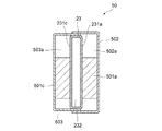
熱電発電モジュール50の具体的な構成について、図3を参照しながら説明する。図3は、図2に示す熱交換器単体部品23及び熱電発電モジュール50近傍を拡大した図であり、熱電発電モジュール50についても断面を示す図である。
A specific configuration of the thermoelectric
図3に示すように、熱電発電モジュール50は、一対の熱電発電素子501a,501cと、カバー502と、カバー503とによって構成されている。熱電発電素子501aは、熱交換器単体部品23の環状側部231aに当接するように設けられている。熱電発電素子501cは、熱交換器単体部品23の環状側部231cに当接するように設けられている。
As illustrated in FIG. 3, the thermoelectric
熱電発電素子501a,501cが排気ガスに直接接触することは好ましくないので、カバー502、503で覆われている。具体的には、熱電発電素子501aを覆い、熱交換器単体部品23の環状側部231aとの間に閉空間502aを形成するように、カバー502は配置されている。同様に、熱電発電素子501cを覆い、熱交換器単体部品23の環状側部231cとの間に閉空間503aを形成するように、カバー503は配置されている。閉空間502a,503aには不活性ガスが封入されている。
Since it is not preferable that the
本実施形態の熱電発電素子501a,501cは直方体形状であり、カバー502,503を含む熱電発電モジュール50も直方体形状である。略円形の熱交換器単体部品23に対して、略直方体形状の熱電発電モジュール50がどのように配置されているかについて、図4を参照しながら説明する。図4は、図2のI−I断面を示す断面図である。
The thermoelectric
図4に示すように、略円形の熱交換器単体部品23の円周方向において、熱電発電モジュール50は、4つ設けられている。隣接する熱電発電モジュール50の間には当然ながら隙間ができるので、内部熱交換流路401(図2参照)に排気ガスを導入するとその隙間にも流れてしまい、熱電発電モジュール50近傍に効率的に排気ガスを導入することができない。
As shown in FIG. 4, four thermoelectric
そこで本実施形態では、排気ガスガイド部としての案内側壁60を設けている。案内側壁60は、熱交換流路ZB1から熱交換流路ZB2へ流れる排気ガスを熱電発電モジュール50近傍に導くように配置されている。具体的には、案内側壁60は、内筒11から外筒20に向かって延び、その方向における熱電発電モジュール50の左右いずれか一端に沿うように配置されている。一つの熱電発電モジュール50に対しては、一端側に沿うように設けられてなる案内側壁60と、他端側に沿うように設けられてなる案内側壁60とが配置されている。また、隣接する熱電発電モジュール50の一方の一端側に沿う案内側壁60と、他方の他端側に沿う案内側壁60とは、断面視L字状となるように内筒11側において互いに繋がっており、熱電発電モジュール50が配置されていない領域に排気ガスが流れないように構成されている。
Therefore, in this embodiment, a
案内側壁60は、熱交換器単体部品23とは別個の部品として形成し、熱交換器単体部品23に取り付けてもよく、熱交換器単体部品23と一体的に設けてもよい。案内側壁60を熱交換器単体部品23と一体的に設ける場合には、環状側部231a,231cに凹凸を設けることで形成することも好ましい。例えば、環状側部231a,231cに凹部を形成し、その凹部に熱電発電モジュール50を配置することで、その凹部側壁が案内側壁60となるように形成することも好ましい。
The
尚、図には明示していないけれども、複数の熱電発電モジュール50は電気的には直接に接続され、図示しない電力取り出し線によって外部に電気を取り出すことが可能なように構成されている。
Although not explicitly shown in the drawing, the plurality of thermoelectric
上記実施形態は、一例に過ぎず、発明の要旨を逸脱しない範囲で、種々の省略、置き換え、変更を行うことができる。 The above embodiment is merely an example, and various omissions, replacements, and changes can be made without departing from the scope of the invention.
HE:熱電発電装置
10:上流側排気管
11:内筒
12:下流側排気管
20:外筒
21:媒体入口部
22:媒体出口部
23:熱交換器単体部品
24:上流側エンドプレート
25:下流側エンドプレート
30:切替バルブ
ZA:上流側主流路
ZB:熱交換流路
ZB1:熱交換流路
ZB2:熱交換流路
ZC:下流側主流路
112:側部流出口
113:主流出口
201:副流出口
231a:環状側部
231b:内側円環側部
231c:環状側部
231d:外側円環側部
232:内部空間
40:熱交換器
401:内部熱交換流路
50:熱電発電モジュール
501a,501c:熱電発電素子
502:カバー
502a:内部空間
503:カバー
503a:内部空間
60:案内側壁
HE: Thermoelectric power generator 10: Upstream exhaust pipe 11: Inner cylinder 12: Downstream exhaust pipe 20: Outer cylinder 21: Medium inlet 22: Medium outlet 23: Heat exchanger single component 24: Upstream end plate 25: Downstream end plate 30: Switching valve ZA: Upstream main channel ZB: Heat exchange channel ZB1: Heat exchange channel ZB2: Heat exchange channel ZC: Downstream main channel 112: Side outlet 113: Main outlet 201: Sub-outlet 231a:
Claims (1)
上流側から流れ込む排気ガスを受け入れる受入口と、その受け入れた排気ガスを下流側に送り出す主送出口と、を繋ぐ主流路の一部を形成する内側部材と、
前記内側部材を囲むように配置され、前記内側部材との間で熱交換流路を形成する外側部材と、
前記熱交換流路において前記内側部材を囲むように配置され、排気ガスと熱交換媒体との間で熱交換を行う熱交換器と、
前記熱交換器に当接して設けられる熱電発電モジュールと、を備え、
前記熱交換流路は、前記熱交換器と前記内側部材との間に形成される第1熱交換流路と、前記熱交換器と前記外側部材との間に形成される第2熱交換流路と、を有し、
排気ガスは熱交流出口から前記熱交換流路に流れ出し、前記熱交換流路に流れ出した排気ガスが、前記熱交換器の内側から外側に向かう径方向に流れて前記第1熱交換流路から前記第2熱交換流路に至るように構成され、
排気ガスが前記第1熱交換流路から前記第2熱交換流路に流れる間に前記熱電発電モジュール近傍に導かれるように設けられてなる排気ガスガイド部を備えることを特徴とする熱電発電装置。
A thermoelectric generator that generates power using heat of exhaust gas discharged from an internal combustion engine,
An inner member that forms a part of the main flow path connecting the receiving port that receives the exhaust gas flowing from the upstream side and the main sending port that sends the received exhaust gas to the downstream side;
An outer member arranged to surround the inner member and forming a heat exchange channel with the inner member;
A heat exchanger disposed so as to surround the inner member in the heat exchange flow path, and performing heat exchange between the exhaust gas and the heat exchange medium;
A thermoelectric generation module provided in contact with the heat exchanger,
The heat exchange flow path includes a first heat exchange flow path formed between the heat exchanger and the inner member, and a second heat exchange flow formed between the heat exchanger and the outer member. Road, and
Exhaust gas flows out from the heat exchange outlet to the heat exchange flow path, and the exhaust gas flowed out to the heat exchange flow path flows in the radial direction from the inside to the outside of the heat exchanger and from the first heat exchange flow path. Configured to reach the second heat exchange flow path,
A thermoelectric power generator comprising an exhaust gas guide portion provided so as to be led to the vicinity of the thermoelectric power generation module while exhaust gas flows from the first heat exchange channel to the second heat exchange channel. .
Priority Applications (2)
| Application Number | Priority Date | Filing Date | Title |
|---|---|---|---|
| JP2014010766A JP6173932B2 (en) | 2014-01-23 | 2014-01-23 | Thermoelectric generator |
| PCT/JP2015/050603 WO2015111459A1 (en) | 2014-01-23 | 2015-01-13 | Thermoelectric power-generation device |
Applications Claiming Priority (1)
| Application Number | Priority Date | Filing Date | Title |
|---|---|---|---|
| JP2014010766A JP6173932B2 (en) | 2014-01-23 | 2014-01-23 | Thermoelectric generator |
Publications (3)
| Publication Number | Publication Date |
|---|---|
| JP2015137616A JP2015137616A (en) | 2015-07-30 |
| JP2015137616A5 JP2015137616A5 (en) | 2017-02-09 |
| JP6173932B2 true JP6173932B2 (en) | 2017-08-02 |
Family
ID=53681267
Family Applications (1)
| Application Number | Title | Priority Date | Filing Date |
|---|---|---|---|
| JP2014010766A Expired - Fee Related JP6173932B2 (en) | 2014-01-23 | 2014-01-23 | Thermoelectric generator |
Country Status (2)
| Country | Link |
|---|---|
| JP (1) | JP6173932B2 (en) |
| WO (1) | WO2015111459A1 (en) |
Families Citing this family (7)
| Publication number | Priority date | Publication date | Assignee | Title |
|---|---|---|---|---|
| CN108026817B (en) * | 2016-01-22 | 2019-12-20 | 双叶产业株式会社 | Integrated exhaust heat recovery device |
| CN108026821A (en) * | 2016-01-22 | 2018-05-11 | 双叶产业株式会社 | Exhaust gas heat recovery device |
| GB2549123B (en) * | 2016-04-06 | 2019-10-09 | Jaguar Land Rover Ltd | Energy recovery unit for vehicle use |
| TWI620159B (en) | 2016-11-15 | 2018-04-01 | 新漢股份有限公司 | Fire scene evacuation guiding device |
| KR101929993B1 (en) | 2017-02-27 | 2018-12-18 | 주식회사 리빙케어 | Multiple Thermoelectric Generator |
| KR102416128B1 (en) | 2017-09-13 | 2022-07-04 | 현대자동차주식회사 | Charing apparatus and vehicle comprising the same, control method for charing apparatus |
| KR102095242B1 (en) * | 2017-12-04 | 2020-04-01 | 엘지이노텍 주식회사 | Heat conversion device |
Family Cites Families (5)
| Publication number | Priority date | Publication date | Assignee | Title |
|---|---|---|---|---|
| JPS62112473U (en) * | 1985-12-27 | 1987-07-17 | ||
| DE102008023937A1 (en) * | 2008-05-16 | 2009-11-19 | Emitec Gesellschaft Für Emissionstechnologie Mbh | Device for generating electrical energy from exhaust heat |
| US8443593B2 (en) * | 2008-12-12 | 2013-05-21 | Westcast Industries, Inc. | Liquid-cooled exhaust valve assembly |
| WO2012095947A1 (en) * | 2011-01-11 | 2012-07-19 | 国立大学法人東京大学 | Heat exchanger for thermal engine |
| JP5737151B2 (en) * | 2011-11-18 | 2015-06-17 | トヨタ自動車株式会社 | Thermoelectric generator |
-
2014
- 2014-01-23 JP JP2014010766A patent/JP6173932B2/en not_active Expired - Fee Related
-
2015
- 2015-01-13 WO PCT/JP2015/050603 patent/WO2015111459A1/en active Application Filing
Also Published As
| Publication number | Publication date |
|---|---|
| WO2015111459A1 (en) | 2015-07-30 |
| JP2015137616A (en) | 2015-07-30 |
Similar Documents
| Publication | Publication Date | Title |
|---|---|---|
| JP6173932B2 (en) | Thermoelectric generator | |
| JP6194309B2 (en) | Exhaust heat recovery device | |
| JP6113143B2 (en) | Device having a heat exchanger for a thermoelectric generator of a motor vehicle | |
| JP5696031B2 (en) | Exhaust heat recovery device | |
| CN107923653B (en) | Heat exchanger | |
| JP6011485B2 (en) | Thermoelectric generator | |
| JP2015137616A5 (en) | ||
| JPWO2018116370A1 (en) | Heat exchanger | |
| JP6139865B2 (en) | Thermoelectric generator for vehicles | |
| JP5962570B2 (en) | Rotating electric machine | |
| KR102415658B1 (en) | Cooling water heating apparatus for electric vehicle | |
| TWI429171B (en) | Cooling module and water-cooled motor system using the same | |
| JP7044781B2 (en) | Heat transfer equipment | |
| WO2016043080A1 (en) | Exhaust heat recovery apparatus | |
| CN107850342B (en) | Heat exchanger | |
| US20180149112A1 (en) | Heat exchanger for a motor vehicle | |
| US20170343302A1 (en) | Heat exchanger | |
| KR101717092B1 (en) | Heat exchanger | |
| CN107850340B (en) | Heat exchanger | |
| CN107850341B (en) | Heat exchanger | |
| JP6243158B2 (en) | Exhaust heat recovery device | |
| CN108026816A (en) | Exhaust gas heat recovery device | |
| JP2016061205A (en) | Exhaust heat recovery device | |
| KR102368138B1 (en) | Cooling-water heater | |
| US20160118568A1 (en) | Thermoelectric Element, Assembly and Module, In Particular Intended To Generate An Electric Current In A Motor Vehicle |
Legal Events
| Date | Code | Title | Description |
|---|---|---|---|
| A521 | Request for written amendment filed |
Free format text: JAPANESE INTERMEDIATE CODE: A523 Effective date: 20161220 |
|
| A621 | Written request for application examination |
Free format text: JAPANESE INTERMEDIATE CODE: A621 Effective date: 20161220 |
|
| TRDD | Decision of grant or rejection written | ||
| A01 | Written decision to grant a patent or to grant a registration (utility model) |
Free format text: JAPANESE INTERMEDIATE CODE: A01 Effective date: 20170619 |
|
| A61 | First payment of annual fees (during grant procedure) |
Free format text: JAPANESE INTERMEDIATE CODE: A61 Effective date: 20170705 |
|
| R150 | Certificate of patent or registration of utility model |
Ref document number: 6173932 Country of ref document: JP Free format text: JAPANESE INTERMEDIATE CODE: R150 |
|
| R250 | Receipt of annual fees |
Free format text: JAPANESE INTERMEDIATE CODE: R250 |
|
| R250 | Receipt of annual fees |
Free format text: JAPANESE INTERMEDIATE CODE: R250 |
|
| R250 | Receipt of annual fees |
Free format text: JAPANESE INTERMEDIATE CODE: R250 |
|
| LAPS | Cancellation because of no payment of annual fees |