JP6173868B2 - Spray nozzle and combustion apparatus equipped with spray nozzle - Google Patents
Spray nozzle and combustion apparatus equipped with spray nozzle Download PDFInfo
- Publication number
- JP6173868B2 JP6173868B2 JP2013214513A JP2013214513A JP6173868B2 JP 6173868 B2 JP6173868 B2 JP 6173868B2 JP 2013214513 A JP2013214513 A JP 2013214513A JP 2013214513 A JP2013214513 A JP 2013214513A JP 6173868 B2 JP6173868 B2 JP 6173868B2
- Authority
- JP
- Japan
- Prior art keywords
- spray
- spray nozzle
- fluid
- mixed fluid
- combustion
- Prior art date
- Legal status (The legal status is an assumption and is not a legal conclusion. Google has not performed a legal analysis and makes no representation as to the accuracy of the status listed.)
- Active
Links
Images


Description
本発明は、噴霧ノズル及び噴霧ノズルを備えた燃焼装置に係り、特に液体燃料(噴霧流体)を気体(噴霧用媒体)を使用して微粒化する二流体噴霧方式の噴霧ノズル、及びこの噴霧ノズルを備えた燃焼装置に関するものである。 BACKGROUND OF THE INVENTION 1. Field of the Invention The present invention relates to a spray nozzle and a combustion apparatus equipped with a spray nozzle, and more particularly, a two-fluid spray type spray nozzle that atomizes liquid fuel (a spray fluid) using a gas (a spray medium), and the spray nozzle It is related with the combustion apparatus provided with.
ガスタービンの燃焼器等の燃焼装置では燃料の多様化と高い環境性能の両立が求められる。 Combustion devices such as gas turbine combustors are required to achieve both diversification of fuel and high environmental performance.
燃料の多様化については、天然ガスに代表される燃焼ガスのほか、軽油やA重油等の液体燃料も用いられ、一部のガスタービンでは、燃料の供給状況に応じて燃料ガスと液体燃料を使用できる、所謂、デュアルフューエルと呼ばれるガスタービン燃焼器も使用される。 Regarding fuel diversification, in addition to combustion gas typified by natural gas, liquid fuels such as light oil and heavy fuel oil A are also used. Some gas turbines use fuel gas and liquid fuel according to the fuel supply status. A so-called dual-fuel gas turbine combustor that can be used is also used.
これらの燃焼装置では、燃焼により排出される窒素酸化物(NOx)や一酸化窒素(CO)、煤塵の低減が求められる。窒素酸化物(NOx)の低減に対して、ガスタービン燃焼器では、空気中の窒素が高温で参加されて生じるサーマルNOxの低減を中心に開発がすすめられている。 In these combustion apparatuses, reduction of nitrogen oxides (NOx), nitrogen monoxide (CO), and soot discharged by combustion is required. In order to reduce nitrogen oxides (NOx), gas turbine combustors have been developed with a focus on reducing thermal NOx generated by the participation of nitrogen in the air at high temperatures.
ガスタービン燃焼器のサーマルNOxの低減には、燃料と空気を予め混合させたうえで燃焼させる予混合燃焼方式の適用が有効である。この燃焼方式では燃料と空気との比率を燃焼場で一定にすることで局所的な高温場を生成せず、サーマルNOxの生成を抑制できる。 In order to reduce the thermal NOx of the gas turbine combustor, it is effective to apply a premixed combustion method in which fuel and air are mixed in advance and burned. In this combustion method, by making the ratio of fuel and air constant in the combustion field, a local high temperature field is not generated, and generation of thermal NOx can be suppressed.
一方、この燃焼方式のガスタービン燃焼器では、安定燃焼範囲が狭く、未燃焼分としてCOや煤塵が生じやすい。 On the other hand, in this combustion type gas turbine combustor, the stable combustion range is narrow, and CO and soot are easily generated as unburned components.
液体燃料をガスタービン燃焼器に使用する場合、液体燃料を微粒化し空気と混合を促進することがNOxの低減に望ましい。たとえば予混合燃焼方式のガスタービン燃焼器において、液体燃料と空気を予め混合させるうえで、液体燃料の微粒化を進めると、空気との混合が容易となる。 When liquid fuel is used in a gas turbine combustor, it is desirable to reduce the NOx by atomizing the liquid fuel and promoting mixing with air. For example, in a premixed combustion type gas turbine combustor, when the liquid fuel and air are mixed in advance and the atomization of the liquid fuel is advanced, mixing with the air becomes easy.
また、微粒化を進めることで液体燃料の重量当たりの表面積が増し、燃焼反応が早まる。このため未燃焼分が発生しにくくなり、燃焼装置から発生するCOや煤塵量を低減できる。 Further, by promoting atomization, the surface area per weight of the liquid fuel increases, and the combustion reaction is accelerated. For this reason, it is difficult to generate unburned components, and the amount of CO and dust generated from the combustion device can be reduced.
液体燃料を微粒化する噴霧ノズルの形式のひとつに、液体燃料(噴霧流体)に噴霧用媒体として空気や蒸気を供給し、噴霧流体と混合することで微粒化する二流体噴霧方式がある。 One type of spray nozzle that atomizes liquid fuel is a two-fluid spray method in which air or steam is supplied as a spray medium to liquid fuel (atomizing fluid) and is atomized by mixing with the atomizing fluid.
この二流体噴霧方式は、噴霧流体に圧力を加えて噴霧する方式と比べて液体燃料の使用量の増減に対する微粒化性能の変化が小さく、燃焼負荷の変化が必要な燃焼装置で一般に使用される。 This two-fluid spraying method is generally used in a combustion apparatus that requires a change in combustion load because the change in atomization performance with respect to increase or decrease in the amount of liquid fuel used is small compared to the method of spraying by applying pressure to the spray fluid. .
二流体噴霧方式の噴霧ノズル(以下、単に噴霧ノズルと記載)では、微粒化性能を高めるとともに噴霧用媒体の使用量や圧力を低減して、噴霧に必要なエネルギー使用量を減らすことが望ましい。このため、噴霧用媒体の混合方法等の検討がされてきた。 In a two-fluid spray type spray nozzle (hereinafter simply referred to as a spray nozzle), it is desirable to improve atomization performance and reduce the amount of spray medium used and the pressure to reduce the amount of energy required for spraying. For this reason, studies have been made on methods for mixing spraying media.
特開昭62−186112号公報(特許文献1)に噴霧流体と噴霧用媒体を出口孔の上流側の空間(内部混合室)で混合させ、混合後の混合流体を多数の出口孔から噴出させる内部混合方式の噴霧ノズルの例を示す。 In Japanese Patent Laid-Open No. 62-186112 (Patent Document 1), a spray fluid and a spray medium are mixed in a space upstream of the outlet hole (internal mixing chamber), and the mixed fluid after mixing is ejected from a number of outlet holes. The example of the spray nozzle of an internal mixing system is shown.
混合室で噴霧流体と噴霧用媒体を混合させることで両者の混合を促進し、その後、多数の出口孔から噴出させることで微粒化が促進する。 Mixing the atomizing fluid and the atomizing medium in the mixing chamber promotes the mixing of the two, and then the atomization is facilitated by ejecting from a number of outlet holes.
特開平9−239299号公報(特許文献2)に噴霧流体と噴霧用媒体を混合後の混合流体を噴霧ノズルの出口孔近傍で対向させて供給し、対向した混合流体の流れを衝突させることで微粒化を促進させる方法の噴霧ノズルの例を示す。 In Japanese Patent Laid-Open No. 9-239299 (Patent Document 2), the mixed fluid after mixing the spray fluid and the spray medium is supplied facing each other in the vicinity of the outlet hole of the spray nozzle, and the flow of the opposed mixed fluid is collided. The example of the spray nozzle of the method of promoting atomization is shown.
この方式は噴霧ノズルの出口孔から扇状に噴霧されるため、ファンスプレ―式とも呼ばれる。ファンスプレ―式の噴霧ノズルでは、噴霧用媒体を出口孔の上流側の流路にて噴霧流体と混合させ、混合流体を噴霧孔近傍で相互に衝突させる。噴霧流体と噴霧用媒体との混合流体とすることで、噴霧流体の衝突力は単独の場合よりも強まり、噴霧流体は微細化される。 Since this method is sprayed in a fan shape from the outlet hole of the spray nozzle, it is also called a fan spray type. In the fan spray type spray nozzle, the spray medium is mixed with the spray fluid in the flow path upstream of the outlet hole, and the mixed fluid collides with each other in the vicinity of the spray hole. By using a mixed fluid of the spray fluid and the spray medium, the collision force of the spray fluid becomes stronger than that of a single fluid, and the spray fluid is miniaturized.
前記特開昭62−186112号公報に開示された二流体噴霧ノズルは、噴霧流体と噴霧用媒体を内部混合室で混合させ、複数の出口孔から噴出させる。内部混合室で混合流体が完全に混合することが望ましいが、噴霧流体と噴霧用媒体の圧力や流量の条件により両者の混合比率に局所的な違いが生じることがある。 The two-fluid spray nozzle disclosed in Japanese Patent Application Laid-Open No. 62-186112 mixes a spray fluid and a spray medium in an internal mixing chamber and ejects the mixture from a plurality of outlet holes. Although it is desirable that the mixed fluid be completely mixed in the internal mixing chamber, there may be a local difference in the mixing ratio between the two depending on the pressure and flow rate conditions of the spray fluid and the spray medium.
この場合、複数設けられた出口孔毎で噴霧流体と噴霧用媒体の混合比率が変動し、一部の出口孔からの噴霧の微粒化が他の出口からの噴霧に比べて悪化する場合がある。 In this case, the mixing ratio of the spray fluid and the spray medium fluctuates for each of the plurality of outlet holes provided, and atomization of the spray from some of the outlet holes may be worse than spray from other outlets. .
前記特開平9−239299号公報に開示された二流体噴霧ノズルは、噴霧流体と噴霧用媒体を複数の混合部で混合する。このため、それぞれの混合部の流路断面積を規定することで、噴霧流体と噴霧用媒体の混合比率のばらつきは前記特開昭62−186112号公報に示される噴霧ノズルに比べて小さくなる。 The two-fluid spray nozzle disclosed in Japanese Patent Laid-Open No. 9-239299 mixes a spray fluid and a spray medium in a plurality of mixing sections. For this reason, by defining the flow path cross-sectional area of each mixing section, the variation in the mixing ratio of the spray fluid and the spray medium becomes smaller than that of the spray nozzle disclosed in Japanese Patent Application Laid-Open No. 62-186112.
しかし、噴霧流体と噴霧用媒体の混合部が多く流路構造が複雑となる。また、混合部では上流側から接続する噴霧流体の流路と噴霧用媒体の流路が交差するため、混合部の壁面には噴霧流体や噴霧用媒体が角度をもって衝突しやすい。 However, there are many mixing parts of the spray fluid and the spray medium, and the flow path structure becomes complicated. In addition, since the flow path of the spray fluid connected from the upstream side and the flow path of the spray medium intersect at the mixing section, the spray fluid and the spray medium tend to collide with the wall surface of the mixing section at an angle.
噴霧流体中の固形分は壁面に対して角度をもって衝突すると壁面が摩耗しやすくなるので、流路の一部が摩耗し、流路断面積が広がると噴霧ノズルを流れる噴霧流体や噴霧用媒体の流量が変わるため、噴霧ノズルの交換が必要となる。 When the solid content in the spray fluid collides with the wall surface at an angle, the wall surface is easily worn, so that when the flow passage is partially worn and the cross-sectional area of the flow channel is widened, the spray fluid and the spray medium flowing through the spray nozzle Since the flow rate changes, it is necessary to replace the spray nozzle.
本発明の目的は、噴霧流体の微粒化の促進と、噴霧流体の微細化に用いる噴霧用媒体の使用量の低減または加圧力の低減とを両立させた噴霧ノズル及び噴霧ノズルを備えた燃焼装置を提示することにある。 An object of the present invention is to provide a spray nozzle and a combustion apparatus equipped with the spray nozzle that can achieve both atomization of the spray fluid and reduction of the amount of spray medium used for atomization of the spray fluid or reduction of the applied pressure. Is to present.
本発明の噴霧ノズルは、噴霧流体を噴霧用媒体と混合した混合流体を噴霧する噴霧ノズルであって、前記噴霧ノズルは前記噴霧流体を供給する噴霧流体流路と、前記噴霧用媒体を供給する噴霧用媒体流路と、前記噴霧流体流路と噴霧用媒体流路が接続する噴霧ノズル先端部で構成され、前記噴霧ノズル先端部には、前記噴霧流体流路と噴霧用媒体流路を連通させて、該噴霧流体流路を流下した前記噴霧流体と該噴霧用媒体流路を流下した前記噴霧用媒体を混合して混合流体にする混合室を設け、前記混合室の下流側となる前記噴霧ノズル先端部に、前記混合室で混合された混合流体を分岐した複数の混合流体流路に分岐する分岐部を形成し、前記分岐部の下流側となる前記噴霧ノズル先端部に、該分岐部で分岐した混合流体を流下させる複数の混合流体流路を配設すると共に、これらの複数の混合流体流路の下流側は混合流体を対向して流下して混合流体が合流する合流部を形成するように対向させて配設し、前記混合流体流路に形成した合流部と連通して該合流部で混合した混合流体を噴霧ノズルから外部に噴霧する出口孔を設けたことを特徴とする。 The spray nozzle of the present invention is a spray nozzle that sprays a mixed fluid obtained by mixing a spray fluid with a spray medium, and the spray nozzle supplies a spray fluid channel that supplies the spray fluid and the spray medium. A spray medium flow path, and a spray nozzle tip connected to the spray fluid flow path and the spray medium flow path, and the spray fluid flow path and the spray medium flow path communicated with the spray nozzle tip. by, providing a mixing chamber for the atomizing fluid and the spray medium flow path mixed fluid by mixing the spray medium flowing down the flowing down the the spray fluid flow path, the downstream side of the mixing chamber the A branch portion that branches into a plurality of mixed fluid flow paths branched from the mixed fluid mixed in the mixing chamber is formed at the tip of the spray nozzle, and the branch is formed at the tip of the spray nozzle that is downstream of the branch. Plural flow of mixed fluid branched off The mixed fluid flow path is disposed, and the downstream sides of the plurality of mixed fluid flow paths are disposed to face each other so as to form a merging portion where the mixed fluid flows down and the mixed fluid merges, An outlet hole is provided that communicates with a merge portion formed in the mixed fluid flow path and sprays the mixed fluid mixed in the merge portion to the outside from a spray nozzle.
本発明の噴霧ノズルを備えた燃焼装置は、噴霧ノズルとして請求項1乃至6のいずれか1項に記載の噴霧ノズルを用い、液体燃料を噴霧流体として前記噴霧ノズルに供給し、燃焼用空気を噴霧用媒体として前記噴霧ノズルに供給することを特徴とする。 A combustion apparatus equipped with a spray nozzle according to the present invention uses the spray nozzle according to any one of claims 1 to 6 as a spray nozzle, supplies liquid fuel as a spray fluid to the spray nozzle, and supplies combustion air. A spraying medium is supplied to the spray nozzle.
また本発明の噴霧ノズルを備えた燃焼装置は、噴霧ノズルとして請求項1乃至6のいずれか1項に記載の噴霧ノズルを用い、液体燃料を噴霧流体として前記噴霧ノズルに供給し、燃焼用空気の一部を噴霧用媒体として圧縮して前記噴霧ノズルに供給することを特徴とする。 Moreover, the combustion apparatus provided with the spray nozzle of the present invention uses the spray nozzle according to any one of claims 1 to 6 as the spray nozzle, supplies liquid fuel to the spray nozzle as a spray fluid, and burns air. A part of the above is compressed as a spraying medium and supplied to the spray nozzle.
また本発明の噴霧ノズルを備えた燃焼装置は、燃焼装置として液体燃料を使用するガスタービン燃焼器と、ガスタービン燃焼器に液体燃料を供給する燃料供給系統と、ガスタービン燃焼器に燃焼用空気を供給する燃焼用空気供給系統と、前記ガスタービン燃焼器で発生した燃焼排ガスによって駆動されるガスタービンと、ガスタービン燃焼器に燃焼用空気を供給する圧縮機とを備えており、
前記燃焼装置で使用する噴霧ノズルとして、請求項1乃至6のいずれか1項に記載の噴霧ノズルを備えたことを特徴とする
A combustion apparatus having a spray nozzle according to the present invention includes a gas turbine combustor that uses liquid fuel as a combustion apparatus, a fuel supply system that supplies liquid fuel to the gas turbine combustor, and combustion air to the gas turbine combustor. A combustion air supply system, a gas turbine driven by combustion exhaust gas generated in the gas turbine combustor, and a compressor for supplying combustion air to the gas turbine combustor,
The spray nozzle according to any one of claims 1 to 6 is provided as a spray nozzle used in the combustion device.
本発明によれば、噴霧流体の微粒化の促進と、噴霧流体の微細化に用いる噴霧用媒体の使用量の低減または加圧力の低減とを両立させた噴霧ノズル及び噴霧ノズルを備えた燃焼装置が実現できる。 ADVANTAGE OF THE INVENTION According to this invention, the combustion apparatus provided with the spray nozzle and spray nozzle which made compatible the acceleration | stimulation of atomization of a spray fluid, and the reduction of the usage-amount of the spraying medium used for atomization of the spray fluid, or the reduction of a pressurization force. Can be realized.
本発明の実施例である噴霧ノズルと、その噴霧ノズルを備えた燃焼装置について、図面を用いて以下に説明する。 A spray nozzle which is an embodiment of the present invention and a combustion apparatus including the spray nozzle will be described below with reference to the drawings.
本発明の第1実施例である噴霧ノズル31について図1及び図2を用いて説明する。
A
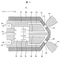
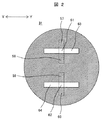
図1に本発明の第1実施例である噴霧ノズル31の先端部の断面図を示す。図2は図1の第1実施例の噴霧ノズル31を噴霧流体の供給方向の下流側から見た平面図である。
FIG. 1 shows a cross-sectional view of the tip of a
図1及び図2に示した本実施例の噴霧ノズル31は、液体燃料2を噴霧流体41として圧力を加えて供給し、別の流体(圧縮空気や蒸気等)を噴霧用媒体42として圧力を加えて供給し、噴霧ノズル31内で噴霧流体41と噴霧用媒体42を混合した混合流体43を形成し、この混合流体43を噴霧ノズル31の先端部の近傍に配設した混合流体流路57、58、60、59内で対向流にして流下させてそれらの混合流体流路内の合流部81で衝突させることにより混合流体43中の噴霧流体41を微細化し、微細化した噴霧流体41を噴霧ノズル31の先端部に設けた出口孔61、62から外部に噴出させるように構成している。
The
噴霧ノズル31の出口孔61、62から外部に噴霧する混合流体43中の噴霧流体41は直径で100μm未満、出来れば50μm以下に微粒化させることが望ましい。微粒子では体積に占める表面積が大きく、燃焼室からの熱放射により昇温し蒸発し易い。また、液滴としての燃焼反応も速い。
The
一方、直径で150μm以上の粗大粒子は蒸発や燃焼し難く、未燃焼分としてCOや煤塵排出の原因となる。また、噴霧流体と空気との混合が悪いのでNOx排出の原因となる。 On the other hand, coarse particles having a diameter of 150 μm or more are difficult to evaporate or burn and cause CO and dust emission as unburned components. Further, the mixing of the spray fluid and air is poor, which causes NOx emission.
このため、噴霧ノズル31は微粒化を進め、微粒子を増やすことで燃焼反応の促進に寄与する。なお、微粒化の程度は、混合流体43の圧力や噴霧用媒体比(噴霧流体41に対する噴霧用媒体42の割合)により調整できる。
For this reason, the
液体燃料の噴霧流体41を微粒化することで、燃焼用空気との混合を促進し、燃焼装置から排出されるNOxを抑制できる。また、液体燃料を微粒化することで燃焼反応を早め、未燃焼分であるCOや煤塵の排出を抑制できる。なお、燃焼方法は燃料と空気を別途に供給し燃焼させる拡散燃焼方式の燃焼器やボイラにおいても微粒化によるNOxやCO、煤塵の低減効果は得られる。
By atomizing the liquid
本実施例の噴霧ノズル31の先端部の構造について図1と図2を用いて更に説明する。図1と図2に示した本実施例の噴霧ノズル31では、噴霧ノズル31の先端部は内筒部51と外筒部52に分解できる構造となっているが、一体構造であっても良い。
The structure of the tip of the
噴霧ノズル31を構成する内筒部51の最上流側には、液体燃料である噴霧流体41が流れる噴霧流体流路53と、空気又は蒸気である噴霧用媒体42が流れる噴霧用媒体流路54が設けられている。噴霧流体41は軽油やA重油等の液体燃料であり、噴霧用媒体42は加圧された空気や蒸気が一般的である。
On the uppermost stream side of the
噴霧流体41と噴霧用媒体42はそれぞれ、噴霧流体流路53と噴霧用媒体流路54の下流となる内筒部51の内部に設けられた内部混合室55に流入して混合し、この内部混合室55で混合流体43を形成する。
The atomizing
図1に示した本実施例の噴霧ノズル31では、噴霧用媒体42は複数の噴霧用媒体流路56を介して内部混合室55に流入するが、単一の噴霧用媒体流路56から内部混合室55に直接流入するように形成しても良い。
In the
また、噴霧流体41を複数の噴霧流体流路53を介して内部混合室55に流入するように形成しても良い。前記噴霧流体41と噴霧用媒体42は複数の流路を介して内部混合室55に流入させることで、噴霧流体41と噴霧用媒体42の混合が早まる効果がある。
Further, the
内部混合室55の下流側には、該内部混合室55内で噴霧流体41と噴霧用媒体42を混合した混合流体43を、内筒部51の下流側に配設した複数の混合流体流路57〜60に混合流体を分岐する分岐部70を備えている。
On the downstream side of the
前記混合流体流路57〜60は、内筒部51の軸心側に配設された混合流体流路58、59と、外筒52に近接した内筒部51の外周側に配設された混合流体流路57、60から構成されている。
The mixed
混合流体43が流れる外周側に配設された混合流体流路57と軸心側に配設された混合流体流路58は、噴霧ノズル31の先端部に近接したこれらの混合流体流路57、58の下流側が混合流体43を対向して流下するように配設しており、そして前記混合流体流路57、58の下流側の流路内に、対向して流下する混合流体43が互いに衝突して混合流体43中の噴霧流体41が微細化される合流部81を形成した構造となっている。
The mixed
同様に、混合流体43が流れる外周側に配設された混合流体流路60と軸心側に配設された混合流体流路59は、噴霧ノズル31の先端部に近接したこれらの混合流体流路60、59の下流側が混合流体43を対向して流下するように配設しており、そして前記混合流体流路60、59の下流側の流路内に、対向して流下する混合流体43が互いに衝突して混合流体43中の噴霧流体41が微細化される合流部82を形成した構造となっている。
Similarly, the mixed
そして、前記混合流体流路57、58の下流側の合流部81、及び、前記混合流体流路60、59の下流側の合流部82にそれぞれ連通して、噴霧ノズル31の先端からこれらの合流部81、82を経た混合流体43中の噴霧流体41が微細化された扇形の噴霧44として外部に噴出させる開口部となる出口孔61、62が噴霧ノズル31の先端部の外面にそれぞれ設けられている。
Then, they communicate with the merging
本実施例の噴霧ノズル31では、混合流体流路57〜60の下流部は内筒部51の内部と、該内筒部51と外筒部52との境界面に設けられ、出口孔61、62は外筒部52の先端部に設けた長穴63、64と前記混合流体流路57〜60の交差部となる。
In the
本実施例の噴霧ノズル31の場合、内筒部51の外周側に設置された外筒部52の先端部に設けた長穴63、64が、図2に示すように混合流体流路57、58、及び混合流体流路60、59とそれぞれ直交する方向に長手方向を有する矩形状に形成されているため、噴出される混合流体43は、扇形の噴霧44は長穴63、64の長手方向(図2のY−Y方向)に拡大する。
In the case of the
このように流体を衝突させて扁平な扇形の噴霧44を形成する本実施例の噴霧ノズル31のような形式を特にファンスプレ―式噴霧ノズルと呼ぶ。
A type like the
扁平な扇形の噴霧44は一般的な円錐状の噴霧に比べて周囲気体との境界部が長いため、周囲気体との流速差によるせん断力が働きやすい。このため、扇形の噴霧44は一般的な円錐状の噴霧に比べて微粒化が良い特徴がある。
Since the flat fan-shaped
また、扁平な扇形の噴霧44は噴霧の拡大や周囲気体とのせん断力により一般的な円錐状の噴霧に比べて噴霧の運動量が噴霧ノズル近傍で低下しやすい。このため、扁平な扇形の噴霧44は噴霧ノズル近傍に噴霧粒子が滞留しやすい。
In addition, the flat fan-shaped
例えば、本実施例の噴霧ノズル31をガスタービン燃焼器の噴霧ノズルに適用した場合に、この噴霧ノズル31から噴霧流体を扁平な扇形の噴霧44として噴霧すると、噴霧の運動量が低下する。噴霧粒子は燃焼器内の気流に従って流れることで噴霧ノズル31を備えたガスタービン燃焼器の燃焼室の隔壁に付着し難くなり、噴霧粒子がガスタービン燃焼器の燃焼室の隔壁に付着することによる燃焼や液体燃料の変質によるコーキング等の障害を起こし難くなる。
For example, when the
噴霧流体41の微粒化は噴霧用媒体42との混合や、出口孔61、62から噴出後の周囲気体とのせん断力により微粒化が進む。特に効果的に微粒化を進める部分について下記の(A)から(D)の4項目を示す。
The atomization of the atomizing
(A)噴霧ノズル31の内部混合室55での噴霧流体41と噴霧用媒体42の混合。
(A) Mixing of the
(B)内部混合室55から分岐後の個別の混合流体流路での噴霧流体41と噴霧用媒体42の混合。
(B) Mixing of the
(C)噴霧ノズル31の出口孔近傍での噴霧流体41と噴霧用媒体42の混合流体43を相互に衝突させることによる噴霧流体41と噴霧用媒体42の混合の促進。
(C) Promotion of mixing of the
(D)噴霧ノズル31の出口孔から噴出後の混合流体43と周囲気体との流速差によるせん断力。
(D) Shear force due to the difference in flow rate between the
前記項目(A)から(C)は流路内での液体であるの噴霧流体41と気体であるの噴霧用媒体42との混合と液体が気体中に分散することによる微粒化である。
The items (A) to (C) are the mixing of the
前記項目(A)は液体の噴霧流体41と気体の噴霧用媒体42とが混合である。項目(B)は混合流体43が混合流体流路57から60をそれぞれ流下する過程で、流路内の流速差によるせん断力で液体の分散と微粒化が進む部分を示す。
In the item (A), the
項目(C)も混合流体43中での液体の分散と微粒化の一種である。本実施例の噴霧ノズル31の先端部となる出口孔61、62の近傍では、噴霧ノズル31の先端部に近接したこれらの混合流体流路57、58の下流側が混合流体43を対向して流下して合流部81で衝突するように配設していると共に、これらの混合流体流路60、59の下流側が混合流体43を対向して流下して合流部82で衝突するように配設している。
Item (C) is also a kind of dispersion and atomization of the liquid in the
よって、混合流体流路57、58の下流側を対向して流下した混合流体43が、混合流体流路57、58の合流部81で衝突し、混合流体流路60、59の下流側を対向して流下した混合流体43が、混合流体流路60、59の合流部82で衝突することで、混合流体43に強い乱れが生じる。
Therefore, the
この衝突により混合流体43を形成している噴霧流体41と噴霧用媒体42の混合が進んで混合流体43中の噴霧流体41の微細化が促進される。
The collision due to the miniaturization of the atomizing
項目(D)は混合流体43が出口孔61、62から噴出後に周囲気体との流速差で混合流体中の液体である噴霧流体41が強いせん断力を受けることによる微粒化である。
Item (D) is atomization caused by the sprayed
前記項目(C)により混合流体43が衝突することで、出口から噴出する混合流体43は衝突方向と直交する平面に拡がる扁平な扇形の噴霧44を形成する。
When the
扇形の噴霧44は円筒形の噴霧に比べて周囲気体との境界部が長いため、項目(D)による混合流体43中の噴霧流体41の微粒化が促進される特徴を有する。
The fan-shaped
このように、噴霧流体41の微粒化は出口部に近い前記項目(C)と(D)が主となるが、項目(A)、項目(B)で各々の混合流体流路を流れる混合流体43中の噴霧流体41と噴霧用媒体42の比率が決まるため、項目(A)、項目(B)も噴霧流体41の微粒化性能を左右する重要な部分である。
As described above, the atomization of the
本実施例の噴霧ノズル31は、特に、上記項目(A)、項目(B)での混合流体43中の噴霧流体41と噴霧用媒体42の比率のばらつき低減と微粒化促進を図ったものである。噴霧流体41と噴霧用媒体42を内部混合室55で混合させて混合流体とした後にこの混合流体43を分岐し、分岐させた混合流体43を対向流として流下させて衝突させ、更に混合させるとの2段階の混合をすることで、以下の1)から3)に示す効果が生じる。
In particular, the
1)1つ目の効果は、噴霧流体41と噴霧用媒体42を混合した混合流体43の形成の促進と、複数の出口孔61、62での混合流体43中の噴霧流体41と噴霧用媒体42の比率のばらつきの抑制である。これにより微粒化を促進できる。
1) The first effect is that the formation of the
内筒部51の内部に設けた内部混合室55内で噴霧流体41と噴霧用媒体42が合流して混合流体43が形成される際に、それぞれの流れ方向の変化と合流に伴う流れの乱れにより両者が混合して噴霧流体41が微粒化するが、内部混合室55が大きいと流れの乱れが収まり、噴霧流体41と噴霧用媒体42の密度差により両者が分離する可能性がある。
When the
そこで、内部混合室55の下流側に分岐部70を設けて該内部混合室55内で形成された混合流体43が該内部混合室55から下流側に複数の混合流体流路57〜60に分割して流下することで、出口孔61、62から噴出する混合流体43中の噴霧流体41と噴霧用媒体42の比率のばらつきを抑制する。
Therefore, the
また、混合流体43を流下する混合流体流路を複数の混合流体流路57〜60に分岐することで、混合流体43と流路を形成する壁面との間のせん断力により混合流体43には乱れが生じ易くなる。この混合流体43の乱れを利用することで、混合流体43を形成する噴霧流体41と噴霧用媒体42との混合と、混合流体43の微粒化が促進される。
In addition, the mixed fluid channel that flows down the
特許文献1に示す内部混合室の場合、内部混合室の容積により混合状態が変わる。たとえば、内部混合室を狭めると噴霧流体と噴霧用媒体の混合が進む前に出口孔に到達する。 In the case of the internal mixing chamber shown in Patent Document 1, the mixing state varies depending on the volume of the internal mixing chamber. For example, when the internal mixing chamber is narrowed, the outlet hole is reached before the mixing of the spray fluid and the spray medium proceeds.
一方、内部混合室を大きすぎる場合、噴霧流体と噴霧用媒体の混合する際の流れの乱れが収まり、両者の密度差により分離が生じる場合がある。 On the other hand, when the internal mixing chamber is too large, the turbulence of the flow when mixing the spray fluid and the spray medium is settled, and separation may occur due to the density difference between the two.
この混合状態は内部混合室の容積と噴霧流体、噴霧用媒体の流量や圧力条件により変動する。このため、運転条件が変わると微粒化性能も変化することとなる。 This mixing state varies depending on the volume of the internal mixing chamber, the spray fluid, the flow rate of the spray medium, and the pressure conditions. For this reason, if the operating conditions change, the atomization performance also changes.
一方、本実施例の噴霧ノズル31では、噴霧ノズル31に設けた内部混合室55の下流側を複数の混合流体流路に分岐している。噴霧流体41と噴霧用媒体42の流れの乱れが収まり、両者が分離する前に複数の混合流体流路に分岐することで、運転条件に関わらず、噴霧ノズル先端部の出口孔での混合流体43中の噴霧流体41と噴霧用媒体42の比率のばらつきを抑制できる。
On the other hand, in the
また、噴霧流体41と噴霧用媒体42を混合させた混合流体43を複数の混合流体流路に分岐して流下させることで、混合流体43とその流路壁面との間のせん断力により混合流体43には乱れが生じ易くなる。この混合流体43の乱れによって、噴霧流体41と噴霧用媒体42の混合と、噴霧流体41の微粒化が促進されることになる。
Further, the
2)2つ目の効果は、噴霧流体41と噴霧用媒体42とが混合する混合部での摩耗の抑制である。噴霧流体41と噴霧用媒体42を混合する場合、例えば、それぞれの流路を交差させて両者の混合する場合には、両者の混合部の壁面に噴霧流体41や噴霧用媒体42が角度をもって衝突し易い。
2) The second effect is suppression of wear at the mixing portion where the
噴霧流体41中に含まれる固形分は流路の壁面に対して角度をもって衝突すると壁面が摩耗しやすくなる。特に流路が狭いと流路断面積に対する壁面との接触部の割合が増えるので噴霧流体41中の固形分が流路の壁面に衝突する頻度が増え、混合部で摩耗しやすくなる。
If the solid content contained in the
本実施例の噴霧ノズル31では、内筒部51の内部に設けた内部混合室55で噴霧流体41と噴霧用媒体42を合流させて混合流体43を形成している。複数の流路を用いた噴霧流体41と噴霧用媒体42の合流と混合を行う場合に比べて、前記内部混合室55の如く広い空間で両者を混合させているので、流路断面積に対する流路壁面との接触部の割合が小さく、噴霧流体41中の固形分が流路の壁面に衝突する頻度は少ない。
In the
また、内部混合室55の下流側で混合流体43を流下させる流路を分岐して複数の混合流体流路に分割させているが、内部混合室55の下流側では噴霧流体41と噴霧用媒体42はほぼ同じ方向に流れるので、流路壁面に噴霧流体41のみが角度をもって衝突し難い。このため、複数の流路を用いた噴霧流体41と噴霧用媒体42の合流と混合を行う場合に比べて混合部で流路の壁面が摩耗しにくくなる。
Further, the flow path for allowing the
特許文献2に示す複数の流路での混合の場合、混合部の上流側から接続する噴霧流体の流路と噴霧用媒体の流路が交差するため、混合部の壁面に噴霧流体や噴霧用媒体が角度をもって衝突しやすい。
In the case of mixing in a plurality of flow paths shown in
噴霧流体中に含まれる固形分は流路壁面に対して角度をもって衝突すると噴霧流体が流下する流路壁面が摩耗しやすくなる。さらに、この流路が複数の流路に分岐されている場合には、流路断面積に対する流路壁面との接触部の割合が増えるので、噴霧流体に含まれる固形分が流路壁面に衝突する頻度が増える。このため、噴霧流体と噴霧用媒体が混合する混合部で流路壁面が摩耗しやすい。 When the solid content contained in the spray fluid collides with the channel wall surface at an angle, the channel wall surface on which the spray fluid flows is likely to be worn. Furthermore, when this flow path is branched into a plurality of flow paths, the ratio of the contact portion with the flow path wall surface relative to the cross-sectional area of the flow path increases, so that the solid content contained in the spray fluid collides with the flow path wall surface. Increase the frequency of For this reason, the flow path wall surface is easily worn at the mixing portion where the spray fluid and the spray medium are mixed.
一方、本実施例の噴霧ノズル31では、噴霧ノズル31に設けた内部混合室55で噴霧流体41と噴霧用媒体42を合流させて混合流体43を形成している。複数の流路での合流と混合の場合に比べて流路断面積に対する壁面との接触部の割合が小さく、流れ中の固形分が壁面に衝突する頻度は少ない。
On the other hand, in the
また、内部混合室55の下流側で複数の混合流体流路に分岐させるので、噴霧流体41と噴霧用媒体42は同じ方向に流れ、混合部の壁面に噴霧流体のみが角度をもって衝突し難い。このため、複数の流路での合流と混合の場合に比べて混合部で摩耗しにくくなる。
Further, since the fluid is branched into a plurality of mixed fluid flow paths on the downstream side of the
3)3つ目の効果は、噴霧流体41(液体燃料)の変質による流動障害の抑制である。液体燃料は高温の状態で滞留すると、内部の高分子成分が変質し、固体として析出して流路の壁面に付着する、いわゆるコーキングという現象をもたらすことがある。 3) The third effect is suppression of flow disturbance due to alteration of the spray fluid 41 (liquid fuel). When the liquid fuel stays at a high temperature, the polymer component inside changes in quality and may cause a phenomenon called so-called coking, in which it precipitates as a solid and adheres to the wall surface of the flow path.
このコーキングが生じると流路が閉塞し、噴霧ノズルからの噴霧や、噴霧ノズルを備えた燃焼装置の運転の障害となる。コーキングは液体燃料が単独で存在し、かつ高温部にさらされることで生じやすくなる。 When this caulking occurs, the flow path is blocked, which hinders the spraying from the spray nozzle and the operation of the combustion apparatus equipped with the spray nozzle. Caulking is likely to occur when liquid fuel is present alone and is exposed to high temperatures.
例えば、本実施例の噴霧ノズル31をガスタービン燃焼器の噴霧ノズルに適用した場合に、この噴霧ノズル31の先端部はガスタービン燃焼器の燃焼室の内筒に面するため、高温の燃焼ガスからの熱放射により高温となり易い。
For example, when the
このため噴霧ノズル31の先端部では、液体燃料の噴霧流体41を、噴霧流体41と噴霧用媒体42が混合した混合流体43の状態で供給し、かつ高速流で送ることで滞留時間を短くすることが望ましい。
For this reason, at the tip of the
一方、噴霧ノズル31の内筒部51の内部に設けた内部混合室55のように広い空間では、液体の一部が滞留する空間を有するため、内部混合室55を噴霧ノズル31の先端部からできるだけ離すことが望ましい。
On the other hand, a large space such as the
本実施例の噴霧ノズル31では、内筒部51の内部に設けた内部混合室55の下流側に該内部混合室55内で形成した混合流体43を分岐して流下させる複数の混合流体流路を配設することで、噴霧ノズル31の先端部から離れた位置に内部混合室55を設けることができる。
In the
内部混合室55から混合流体43を分岐して流下させる複数の混合流体流路は上述のように流路断面積が狭く、噴霧流体41と噴霧用媒体42の分離が生じ難い。また、流路の壁面を摩耗する可能性が低い。
A plurality of mixed fluid flow paths for branching and flowing the
このため、液体燃料単独での流路や内部混合室55のように広い空間を噴霧ノズルの先端部から離れた位置に形成することで、噴霧ノズル31内の流路でのコーキングの発生とそれに伴う流動障害が生じ難い。
For this reason, by forming a wide space such as the flow path of the liquid fuel alone or the
上記したように、本実施例の噴霧ノズル31では、個々の出口孔から噴出する混合流体43中の噴霧流体41と噴霧用媒体42の比率を一定とし、噴霧流体41の微粒化の促進と噴霧用媒体の使用量の低減や加圧力の低減を両立させることができる。
As described above, in the
また、噴霧流体41と噴霧用媒体42の混合部での摩耗や流路内でのコーキングを抑制し、噴霧ノズル31の使用時間を延ばすことができる。
Further, wear at the mixing portion of the
混合流体43の微粒化により、液体燃料の単位重量当たりの表面積が増加するので、燃焼反応が進み、噴霧ノズル31を備えた燃焼装置出口での未燃焼分である一酸化炭素や煤塵が低減し、燃焼効率を高くできる。また、燃焼反応を早く進めることで、酸素の消費が進み、窒素酸化物の発生を抑えることができる。
Since the surface area per unit weight of the liquid fuel increases due to the atomization of the
さらに、未燃焼分や煤塵、一酸化炭素が低減することで、噴霧ノズル31を備えた燃焼装置に投入する余剰な空気を削減できる。余剰な空気が減ると、燃焼排ガス量も低下し、燃焼排ガスとともに燃焼装置外に放出される顕熱を低下させ、熱効率を高めることができる。
Furthermore, the amount of unburned dust, soot, and carbon monoxide can be reduced, so that excess air that is put into the combustion device provided with the
また、噴霧用媒体42の使用量の抑制や圧力の低減により、噴霧用媒体42の各々の供給や加圧力に使用なエネルギー消費量を低減できる。
In addition, by suppressing the amount of the
なお、図1〜図2に示した第1実施例の噴霧ノズル31では出口孔が出口孔61及び出口孔62との2つある場合について説明したが、出口孔が3つ以上ある場合についても本実施例の噴霧ノズル31を適用することができる。
The
次に本発明の第2実施例である噴霧ノズル31について図3及び図5を用いて説明する。
Next, a
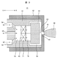
図3は本発明の第2実施例である噴霧ノズル31における先端部の断面図を示し、図5は図3に示す本実施例の噴霧ノズル31を噴霧流体の供給方向の下流側から見た平面図を示している。本実施例の噴霧ノズル31の先端部は内筒部51と外筒部52に分解できる構造であるが、一体構造であっても構わない。
FIG. 3 shows a sectional view of the tip of the
図3及び図5に示した本実施例の噴霧ノズル31は、図1及び図2に示した第1実施例の噴霧ノズル31と基本的な構成及び作用効果は同じであるので、両者に共通した構成の説明は省略し、相違する部分についてのみ以下に説明する。
The
図3及び図5に示した本実施例の噴霧ノズル31では、内部混合室55に旋回流発生器71を備えている。そして、噴霧流体流路53を流下する噴霧流体41と、噴霧用媒体流路54を流下する噴霧用媒体42は、噴霧流体流路53及び噴霧用媒体流路54がそれぞれ連通しており、噴霧ノズル31を構成する内筒部51の内部に設けられた内部混合室55に流入して噴霧流体41と噴霧用媒体42とが混合して混合流体43となる。
In the
そして、内部混合室55で噴霧流体41と噴霧用媒体流路54とが混合して形成された混合流体43は、内部混合室55の下流側に設置された旋回流発生器71を通過することで混合流体43は噴霧ノズル31の軸(図3のX−X方向)に対して周方向の流速成分が誘起される。
Then, the
前記旋回流発生器71を通過した混合流体43は、この旋回流発生器71の下流側に設置された分岐部70によって分岐され、この分岐部70で分岐された混合流体43は混合流体流路57、58の下流側が各々対向して合流する構造となる。この合流部に連通して噴霧ノズルの外面への開口部(出口孔)61が設けられる。
The
本実施例では混合流体流路57、58の下流部は内筒部51と外筒部52の境界面に設けられ、出口孔61は外筒部に設けた長穴63と混合流体流路57、58の交差部となる。噴霧流体41の微粒化は噴霧用媒体42との混合や出口孔61、62からの噴出後の周囲気体とのせん断力により微粒化が進む。
In this embodiment, the downstream portions of the mixed
内部混合室55の下流側で旋回流発生器71を通過することで混合流体43は噴霧ノズルの軸(図3のX−X方向)に対して周方向の流速成分が誘起される。このため混合流体43は内部混合室の外径方向に多く流れ、分岐部70での分岐の際に周方向に分岐することで、それぞれの流路に噴霧流体と噴霧用媒体が同じ比率で流入しやすくなる。
By passing through the
上記したように、本実施例によれば、噴霧流体の微粒化の促進と、噴霧流体の微細化に用いる噴霧用媒体の使用量の低減または加圧力の低減とを両立させた噴霧ノズルが実現できる。 As described above, according to this embodiment, a spray nozzle that achieves both atomization of the spray fluid and reduction in the amount of spray medium used for atomization of the spray fluid or reduction in the applied pressure is realized. it can.
次に本発明の第3実施例である噴霧ノズル31について図4及び図5を用いて説明する。
Next, a
図4は本発明の第3実施例である噴霧ノズル31における先端部の断面図を示し、図5は図3に示す第2実施例の噴霧ノズル31と同様に、図4に示した第3実施例の噴霧ノズル31を噴霧流体の供給方向の下流側から見た平面図を示している。
4 shows a sectional view of the tip of a
本実施例の噴霧ノズル31の先端部も、内筒部51と外筒部52に分解できる構造であるが、一体構造であっても構わない。
The tip portion of the
図3及び図5に示した本実施例の噴霧ノズル31は、図1及び図2に示した第1実施例の噴霧ノズル31と基本的な構成及び作用効果は同じであるので、両者に共通した構成の説明は省略し、相違する部分についてのみ以下に説明する。
The
図3及び図5に示した本実施例の噴霧ノズル31では、内筒部51の内部に設けた内部混合室55の下流側で流路が狭まる流路縮小部72を有した構成となっている。噴霧流体41と噴霧用媒体42はそれぞれの流路53、54の下流に設けられた内部混合室55で混合し、混合流体43となる。
The
内部混合室55の下流側に設けた流路縮小部72を通過することで混合流体43は流速が高まる。そして、流路縮小部72の下流側に設けた分岐部70によって分岐された混合流体43は、分岐した混合流体43を流下させる混合流体流路57、58のうち、噴霧ノズル31の先端部の近傍となる混合流体流路57、58の下流側が混合流体43を対向して流下するように配設すると共に、この対向して流れる混合流体43が衝突して混合する合流部83を該混合流体流路57、58の流路内に形成した構造となっている。
The flow rate of the
この合流部83に噴霧ノズル31の先端部の外面に混合流体43を噴出する開口部(出口孔)61が設けられている。
An opening (outlet hole) 61 for ejecting the
本実施例の噴霧ノズル3では、混合流体流路57、58の下流部は内筒部51と外筒部52の境界面に設けられ、出口孔61は外筒部52の先端部の外面に設けた長穴63と混合流体流路57、58の交差部として形成される。
In the
噴霧流体41の微粒化は噴霧用媒体42との混合や出口孔61からの噴出後の周囲気体とのせん断力により微粒化が進む。
The atomization of the atomizing
内部混合室55の下流側に設けた流路縮小部72を混合流体43が通過することで、内部混合室55内に設けた流路縮小部72の下流側に形成した分岐部70近傍で混合流体43の流速が高まり、混合流体43を形成している噴霧流体41と噴霧用媒体42の混合が更に促進される。
As the mixed fluid 43 passes through the flow
混合流体43を形成している噴霧流体41と噴霧用媒体42の混合を促進させた上で前記分岐部70でこの混合流体43を分岐することで、それぞれの混合流体流路57、58を流下する混合流体43として噴霧流体41と噴霧用媒体42が同じ比率で流入しやすくなる。
After the mixing of the sprayed
なお、図3〜図5に示した第2実施例及び第3実施例の噴霧ノズル31では出口孔61が1つある場合について説明したが、出口孔が2つ以上ある場合についても本実施例の噴霧ノズル31を適用することができる。
Although the
上記したように、本実施例によれば、噴霧流体の微粒化の促進と、噴霧流体の微細化に用いる噴霧用媒体の使用量の低減または加圧力の低減とを両立させた噴霧ノズルが実現できる。 As described above, according to this embodiment, a spray nozzle that achieves both atomization of the spray fluid and reduction in the amount of spray medium used for atomization of the spray fluid or reduction in the applied pressure is realized. it can.
次に本発明の第4実施例である噴霧ノズルを備えた燃焼装置として、噴霧ノズルを備えたガスタービン燃焼器について図6を用いて説明する。 Next, a gas turbine combustor equipped with a spray nozzle as a combustion apparatus equipped with a spray nozzle according to a fourth embodiment of the present invention will be described with reference to FIG.
図6は本実施例の噴霧ノズルを備えたガスタービン燃焼器が設置されたガスタービンプラントの全体構成を示す概略構成図である。図6に示したガスタービンプラントは、空気を圧縮して高圧の燃焼用空気1を生成する圧縮機6と、圧縮機6で生成した燃焼用空気1と燃料2を導入して燃焼し、高温の燃焼ガス3を発生させる燃焼装置を構成する図1〜図5に示した第1実施例〜第3実施例の噴霧ノズル31を備えたガスタービン燃焼器7と、ガスタービン燃焼器7で発生した燃焼ガス3を導入して駆動されるタービン8と、タービン8によって駆動され、電力を発生させる発電機9を有する。
FIG. 6 is a schematic configuration diagram illustrating an overall configuration of a gas turbine plant in which a gas turbine combustor including a spray nozzle according to the present embodiment is installed. The gas turbine plant shown in FIG. 6 introduces and burns a
ガスタービン燃焼器7で発生させた燃焼ガス3によってタービン8を駆動した動力は発電機9を回転して発電すると共に、圧縮機6の駆動用としても用いられる。
The motive power that drives the turbine 8 by the
上記したガスタービンプラントではタービン8で得られた動力で発電機9を駆動して発電する例を示すが、タービン8で得られた動力をたとえば回転機械に使用しても構わない。 In the gas turbine plant described above, an example is shown in which the generator 9 is driven by the power obtained by the turbine 8 to generate power. However, the power obtained by the turbine 8 may be used for a rotating machine, for example.
本実施例となる噴霧ノズル31を備えた燃焼装置であるガスタービン燃焼器7は、燃焼用空気1を導入する外筒11と、該外筒11に取り付けられたエンドカバー12とで密閉された圧力容器を構成している。
A gas turbine combustor 7, which is a combustion apparatus provided with a
外筒11の内部は燃料ノズル31から噴霧された燃料と燃焼用空気を混合させて燃焼し、燃焼ガス3を生成する燃焼空間となる燃焼室13aを内部に形成する内筒13と、この内筒13の下流に該内筒13の流路よりも流路を狭めたトランジションピース14があり、このトランジションピース14の下流でタービン8に接続されている。
The inside of the
燃焼用空気1は外筒11と内筒13の間の空間を通り、内筒13の最上流部(図1のエンドカバー12側)から内筒13内に供給され、燃料2はエンドカバー15を貫通する燃料ノズル31から内筒13内の燃焼室13aに噴霧される。
The combustion air 1 passes through the space between the
内筒13内の燃焼室13aに噴霧された燃料2は燃焼用空気1と混合し、その混合ガスが点火栓16により点火されて燃焼を開始する。
The
ガスタービン燃焼器7では、窒素酸化物(NOx)や一酸化炭素(CO)、煤塵の低減が求められる。このため、燃焼用空気1と燃料2の混合を改良し、燃焼用空気1に旋回流を与える旋回器15や、空気取入口17を介して燃焼用空気1の噴出方向や流速、流量配分を調整して内筒13内の燃焼室13aに燃焼用空気1を流入させている。
The gas turbine combustor 7 is required to reduce nitrogen oxides (NOx), carbon monoxide (CO), and soot. For this reason, the mixing direction of the combustion air 1 and the
また、燃焼用空気1の一部を内筒13の側面に設けた空気導入口19から内筒13内の燃焼室13aに導入して、内筒13の隔壁部を冷却することが望ましい。
In addition, it is desirable to cool a partition portion of the
図6に示す本実施例の噴霧ノズル31を備えたガスタービン燃焼器7に燃料を供給する燃料供給系統について説明すると、本実施例の噴霧ノズル31を備えた燃焼装置であるガスタービン燃焼器7に液体燃料を供給する燃料供給系統には、燃料タンク22と、この燃料タンク22から液体燃料を移送する移送ポンプ23と、移送する燃料を調節する移送調整弁24を備え、前記移送ポンプ23及び移送調整弁24の下流側には該移送ポンプ23及び移送調整弁24を経た液体燃料を加圧する高圧ポンプ25と、燃料の圧力を調節する圧力調整弁26を備えている。
A fuel supply system for supplying fuel to the gas turbine combustor 7 having the
更に、前記高圧ポンプ25及び圧力調整弁26の下流側には該高圧ポンプ25及び圧力調整弁26を経た液体燃料の供給を遮断する遮断弁27と、液体燃料の流量を調節する流量調整弁28を備え、その下流側に該高圧ポンプ25及び圧力調整弁26を経た液体燃料の流量を測定する燃料流量計29と、液体燃料を分配する燃料分配器30が設置されており、前記燃料分配器30で分配された液体燃料2はガスタービン燃焼器7に設置された燃料ノズル31に供給され、この燃料ノズル31から燃料2を内筒13内の燃焼室13aに噴霧して燃焼させるように構成されている。
Further, on the downstream side of the high pressure pump 25 and the pressure regulating valve 26, a shutoff valve 27 for shutting off the supply of liquid fuel via the high pressure pump 25 and the pressure regulating valve 26, and a flow rate regulating valve 28 for adjusting the flow rate of the liquid fuel. And a fuel flow meter 29 for measuring the flow rate of the liquid fuel passing through the high pressure pump 25 and the pressure regulating valve 26, and a fuel distributor 30 for distributing the liquid fuel are installed on the downstream side of the fuel distributor. The
また、ガスタービン燃焼器7に供給される噴霧用空気1は、圧縮機6で圧縮した空気の一部を高圧圧縮機32で昇圧し、この高圧圧縮機32の下流側に設置した圧力・流量調整弁33と空気分配器34を介して噴霧用空気1として燃料ノズル31に供給するように構成されている。
In addition, the atomizing air 1 supplied to the gas turbine combustor 7 is pressurized by a high pressure compressor 32 which is a part of the air compressed by the
この噴霧用空気1は液体燃料2の微粒化に用いられるほか、液体燃料2の供給開始時や停止時に流路や燃料ノズル31内の残留物を除去するパージ用の空気としても用いられる。
The atomizing air 1 is used not only for atomizing the
なお、噴霧用空気1はガスタービンの圧縮機6で得られた圧縮空気を昇圧する方法のほか、単独の圧縮機で得ることも可能である。また、空気に代わり蒸気を用いることも可能である。
The atomizing air 1 can be obtained by a single compressor in addition to the method of increasing the pressure of the compressed air obtained by the
噴霧ノズル31やガスタービン燃焼器7はガスタービンプラントに複数設けられるのが一般的であるが、図6ではその一部のみを記載した。
A plurality of
また、図6に示した本実施例の噴霧ノズル31を備えたガスタービン燃焼器7では、燃料として液体燃料2を使用する場合を例に説明したが、本実施例の噴霧ノズル31を有するガスタービン燃焼器7は、液体燃料のほかに気体燃料を別の系統として有し、燃料の供給状況に応じて気体燃料と液体燃料を使用できるいわゆるデュアルフューエルと呼ばれるガスタービン燃焼器にも適用できる。
Further, in the gas turbine combustor 7 having the
液体燃料は直径で100μm未満、出来れば50μm以下に微粒化させることが望ましい。微粒子では体積に占める表面積が大きく、炉内からの熱放射により昇温し蒸発し易い。また、液滴としての燃焼反応も速い。 The liquid fuel is desirably atomized to a diameter of less than 100 μm, preferably to 50 μm or less. Fine particles have a large surface area in the volume and are likely to evaporate due to the temperature rise by heat radiation from the inside of the furnace. Also, the combustion reaction as droplets is fast.
一方、直径で150μm以上の粗大粒子は蒸発や燃焼し難く、未燃焼分としてCOや煤塵排出の原因となる。また、燃料気体と空気との混合が悪いのでNOx排出の原因となる。このため、噴霧ノズルは微粒化を進め、微粒子を増やすことで燃焼反応の促進に寄与する。なお、微粒化の程度は、混合流体の圧力や噴霧用媒体量(噴霧流体に対する噴霧用媒体の割合)により調整できる。 On the other hand, coarse particles having a diameter of 150 μm or more are difficult to evaporate or burn and cause CO and dust emission as unburned components. Further, since the mixing of the fuel gas and air is poor, it causes NOx emission. For this reason, a spray nozzle advances atomization and contributes to promotion of a combustion reaction by increasing fine particles. The degree of atomization can be adjusted by the pressure of the mixed fluid and the amount of the spray medium (ratio of the spray medium to the spray fluid).
実施例1から3のいずれかに示した本発明の噴霧ノズル31を本実施例に示す燃焼装置に用いることで、噴霧ノズル31の個々の出口孔から噴出する混合流体43中の噴霧流体41と噴霧用媒体42の比率を一定とし、噴霧流体41の微粒化の促進と噴霧用媒体の使用量の低減や加圧力の低減を両立させることができる。
By using the
また、噴霧流体41と噴霧用媒体42の混合部での摩耗や流路内でのコーキングを抑制し、噴霧ノズル31の使用時間を延ばすことができる。
Further, wear at the mixing portion of the
混合流体43の微粒化により、液体燃料の単位重量当たりの表面積が増加するので、燃焼反応が進み、噴霧ノズル31を備えた燃焼装置出口での未燃焼分である一酸化炭素や煤塵が低減し、燃焼効率を高くできる。
Since the surface area per unit weight of the liquid fuel increases due to the atomization of the
また、燃焼反応を早く進めることで、酸素の消費が進み、窒素酸化物の発生を抑え、かつ未燃焼分や煤塵、一酸化炭素が低減することができる。また、噴霧用媒体42の使用量の抑制や圧力の低減により、噴霧用媒体42の各々の供給や加圧力に使用なエネルギー消費量を低減できる。
Further, by proceeding with the combustion reaction quickly, consumption of oxygen proceeds, generation of nitrogen oxides can be suppressed, and unburned matter, soot and carbon monoxide can be reduced. In addition, by suppressing the amount of the
なお、燃焼方法は燃料と空気を別途に供給し燃焼させる拡散燃焼方式の燃焼器やボイラにおいても微粒化によるNOxやCO、煤塵の低減効果は得られる。 In the combustion method, NOx, CO, and dust reduction effects due to atomization can be obtained even in a diffusion combustion type combustor or boiler that separately supplies and burns fuel and air.
次に本発明の第5実施例である噴霧ノズルを備えた燃焼装置として、噴霧ノズルを備えたガスタービン燃焼器について図7を用いて説明する。 Next, a gas turbine combustor provided with a spray nozzle as a combustion apparatus provided with a spray nozzle according to a fifth embodiment of the present invention will be described with reference to FIG.
図7は本実施例の噴霧ノズルを備えたガスタービン燃焼器7bが設置されたガスタービンプラントの全体構成を示す概略構成図である。
FIG. 7 is a schematic configuration diagram showing an overall configuration of a gas turbine plant in which a
図7に示した本実施例の噴霧ノズルを備えたガスタービン燃焼器7bは、図6に示した第4実施例の噴霧ノズルを備えたガスタービン燃焼器7と基本的な構成及び作用効果は同じであるので、両者に共通した構成の説明は省略し、相違する部分についてのみ以下に説明する。
The
図7に示した本実施例の噴霧ノズルを備えたガスタービン燃焼器7bに用いられる噴霧ノズル31は、図1〜図2に示した第1実施例の噴霧ノズル31、並びに図3〜図5に示した第2実施例及び第3実施例の噴霧ノズル31であるので、噴霧ノズル31についての説明は省略する。
The
図7に示した本実施例の噴霧ノズルを備えたガスタービン燃焼器7bにおいて、図6に示した第4実施例の噴霧ノズルを備えたガスタービン燃焼器7と異なっているのは、ガスタービン燃焼器7の内筒13の内部の、燃料ノズル31から噴霧された燃料と燃焼用空気を混合させて燃焼して燃焼ガス3を生成する燃焼空間となる燃焼室13aの上流側であって、燃焼用空気1を旋回して流入させる旋回器15の下流側となる前記燃料ノズル31の周囲に、燃焼用空気1の一部を投入する予混合室18を設けてこの予混合室18で前記噴霧ノズル31から噴出する液体燃料2と燃焼空気1の一部を混合し、下流側の燃焼室13aで燃焼するように構成したものである。
The
そして前記予混合室18は下流側の燃焼室13aと接続されており、この下流側の燃焼室13aの流路断面積が前記予混合室18の流路断面積よりも広い流路断面積を有するように形成されて、本実施例の噴霧ノズルを備えたガスタービン燃焼器7bを構成したものである。
The premixing
ガスタービン燃焼器7の内筒13の上流側に燃焼用空気1と燃料2を燃焼前に混合させる空間を形成する予混合室18を設けることで、燃焼用空気1と燃料2が混合後に燃焼するので、希薄燃焼により燃焼時に温度が局所的に高い部分が形成されない。このため、高い温度での燃焼で生成しやすい窒素酸化物(NOx)を効果的に低減できる。
By providing a
この際、予混合室18の流路断面積を内筒13内の燃焼室13aの流路断面積よりも狭くなるように形成して、予混合室18内の燃焼用空気1と燃料2の流速を早めると、予混合室18内での燃料2の燃焼を抑制し、燃焼用空気1と燃料2の混合を促進することができる。
At this time, the flow passage cross-sectional area of the premixing
実施例1から3のいずれかに示した本発明の噴霧ノズル31を本実施例に示す燃焼装置に用いることで、噴霧ノズル31の個々の出口孔から噴出する混合流体43中の噴霧流体41と噴霧用媒体42の比率を一定とし、噴霧流体41の微粒化の促進と噴霧用媒体の使用量の低減や加圧力の低減を両立させることができる。
By using the
また、噴霧流体41と噴霧用媒体42の混合部での摩耗や流路内でのコーキングを抑制し、噴霧ノズル31の使用時間を延ばすことができる。
Further, wear at the mixing portion of the
混合流体43の微粒化により、液体燃料の単位重量当たりの表面積が増加するので、燃焼反応が進み、噴霧ノズル31を備えた燃焼装置出口での未燃焼分である一酸化炭素や煤塵が低減し、燃焼効率を高くできる。
Since the surface area per unit weight of the liquid fuel increases due to the atomization of the
また、燃焼反応を早く進めることで、酸素の消費が進み、窒素酸化物の発生を抑え、かつ未燃焼分や煤塵、一酸化炭素が低減することができる。また、噴霧用媒体42の使用量の抑制や圧力の低減により、噴霧用媒体42の各々の供給や加圧力に使用なエネルギー消費量を低減できる。
Further, by proceeding with the combustion reaction quickly, consumption of oxygen proceeds, generation of nitrogen oxides can be suppressed, and unburned matter, soot and carbon monoxide can be reduced. In addition, by suppressing the amount of the
1:燃焼用空気、2:燃料、3:燃焼ガス、6:圧縮機、7、7b:ガスタービン燃焼器、8:タービン、9:発電機、11:外筒、12:エンドカバー、13:内筒、13a:燃焼室、14:トランジションピース、15:旋回器、16:点火栓、17:空気取入口、18:予混合室、19:空気導入口、41:噴霧流体、42:噴霧用媒体、43:混合流体、44:扇型噴霧、51:噴霧ノズルの内筒部、52:噴霧ノズルの外筒部、53:噴霧流体流路、54:噴霧用媒体流路、55:内部混合室、56:噴霧用媒体流路、57〜60:混合流体流路、61、62:出口孔、63、64:長穴、70:分岐部、71:旋回流発生器、72:流路縮小部、81〜83:合流部、122:燃料タンク、123:移送ポンプ、124:移送調整弁、125:高圧ポンプ、126:圧力調整弁、127:遮断弁、128:流量調整弁、129燃料流量計、130:燃料分配器、31:噴霧ノズル、132:高圧圧縮機、133:圧力・流量調整弁、134:空気分配器。 1: combustion air, 2: fuel, 3: combustion gas, 6: compressor, 7, 7b: gas turbine combustor, 8: turbine, 9: generator, 11: outer cylinder, 12: end cover, 13: Inner cylinder, 13a: combustion chamber, 14: transition piece, 15: swirler, 16: spark plug, 17: air intake, 18: premixing chamber, 19: air inlet, 41: spray fluid, 42: for spraying Medium, 43: Mixed fluid, 44: Fan-type spray, 51: Inner cylinder part of spray nozzle, 52: Outer cylinder part of spray nozzle, 53: Spray fluid channel, 54: Spray medium channel, 55: Internal mixing Chamber, 56: spraying medium flow path, 57-60: mixed fluid flow path, 61, 62: outlet hole, 63, 64: elongated hole, 70: branching section, 71: swirl flow generator, 72: flow path reduction Part, 81-83: junction part, 122: fuel tank, 123: transfer pump, 124: transfer control Valve: 125: high pressure pump, 126: pressure regulating valve, 127: shutoff valve, 128: flow regulating valve, 129 fuel flow meter, 130: fuel distributor, 31: spray nozzle, 132: high pressure compressor, 133: pressure Flow control valve, 134: air distributor.
Claims (10)
前記噴霧流体を供給する噴霧流体流路と、前記噴霧用媒体を供給する噴霧用媒体流路と、前記噴霧流体流路と噴霧用媒体流路が接続する噴霧ノズル先端部で構成され、
前記噴霧ノズル先端部には、前記噴霧流体流路と噴霧用媒体流路を連通させて、該噴霧流体流路を流下した前記噴霧流体と該噴霧用媒体流路を流下した前記噴霧用媒体を混合して混合流体にする混合室を設け、
前記混合室の下流側となる前記噴霧ノズル先端部に、前記混合室で混合された混合流体を分岐した複数の混合流体流路に分岐する分岐部を形成し、
前記分岐部の下流側となる前記噴霧ノズル先端部に、該分岐部で分岐した混合流体を流下させる複数の混合流体流路を配設すると共に、これらの複数の混合流体流路の下流側は混合流体を対向して流下して混合流体が合流する合流部を形成するように対向させて配設し、
前記混合流体流路に形成した合流部と連通して該合流部で混合した混合流体を噴霧ノズルから外部に噴霧する出口孔を設けたことを特徴とする噴霧ノズル。 In a spray nozzle for spraying a mixed fluid obtained by mixing a spray fluid with a spray medium,
A spray fluid flow path for supplying the spray fluid; a spray medium flow path for supplying the spray medium; and a spray nozzle tip connected to the spray fluid flow path and the spray medium flow path.
Wherein the spray nozzle tip, thereby communicating said atomizing fluid passage and the atomizing medium passage, the atomizing medium flowing down the atomizing fluid and the spray medium flow path flows down the spray fluid flow path Provide a mixing chamber to mix and make a mixed fluid,
Forming a branching portion branching into a plurality of mixed fluid flow paths branched from the mixed fluid mixed in the mixing chamber at the tip of the spray nozzle on the downstream side of the mixing chamber;
A plurality of mixed fluid passages for flowing down the mixed fluid branched at the branch portion are disposed at the tip of the spray nozzle on the downstream side of the branch portion, and the downstream sides of the plurality of mixed fluid passages are Arranged to face each other so as to form a merging part where the mixed fluid flows down and the mixed fluid merges,
An atomizing nozzle comprising an outlet hole that communicates with a merging portion formed in the mixed fluid channel and sprays the mixed fluid mixed in the merging portion from the atomizing nozzle to the outside.
前記出口孔を複数個設置したことを特徴とする噴霧ノズル。 The spray nozzle according to claim 1.
A spray nozzle comprising a plurality of the outlet holes.
前記混合室に流入する前記噴霧流体流路と前記噴霧用媒体流路の少なくとも一方は、複数個配設されていることを特徴とする噴霧ノズル。 The spray nozzle according to claim 1 or 2,
A spray nozzle, wherein at least one of the spray fluid flow path and the spray medium flow path flowing into the mixing chamber is provided in plural.
前記混合室と、前記混合室の下流側に形成した前記分岐部との接続部分に、流路断面積を狭める絞り部を形成したことを特徴とする噴霧ノズル。 The spray nozzle according to claim 1 or 2,
A spray nozzle characterized in that a constriction portion for narrowing a cross-sectional area of a flow path is formed at a connection portion between the mixing chamber and the branch portion formed on the downstream side of the mixing chamber.
前記混合室の流路断面積に対して、前記分岐部で分岐した複数の混合流体流路の流路断面積の合計が小さくなるように形成されていることを特徴とする噴霧ノズル。 The spray nozzle according to claim 1 or 2,
The spray nozzle, wherein the sum of the cross-sectional areas of the plurality of mixed fluid flow paths branched at the branch portion is smaller than the cross-sectional area of the mixing chamber.
前記混合室と、前記混合室の下流側に形成した前記分岐部との間に、前記混合室を流下した混合流体に旋回流を誘起する旋回流発生器が設置されていることを特徴とする噴霧ノズル。 The spray nozzle according to claim 1 or 2,
A swirling flow generator for inducing swirling flow in the mixed fluid flowing down the mixing chamber is installed between the mixing chamber and the branch portion formed on the downstream side of the mixing chamber. Spray nozzle.
噴霧ノズルとして請求項1乃至6のいずれか1項に記載の噴霧ノズルを用い、液体燃料を噴霧流体として前記噴霧ノズルに供給し、燃焼用空気を噴霧用媒体として前記噴霧ノズルに供給することを特徴とする噴霧ノズルを備えた燃焼装置。 A combustion device equipped with a spray nozzle,
The spray nozzle according to any one of claims 1 to 6 is used as a spray nozzle, liquid fuel is supplied to the spray nozzle as a spray fluid, and combustion air is supplied to the spray nozzle as a spray medium. Combustion device with a spray nozzle characterized.
噴霧ノズルとして請求項1乃至6のいずれか1項に記載の噴霧ノズルを用い、液体燃料を噴霧流体として前記噴霧ノズルに供給し、燃焼用空気の一部を噴霧用媒体として圧縮して前記噴霧ノズルに供給することを特徴とする噴霧ノズルを備えた燃焼装置。 A combustion device equipped with a spray nozzle,
The spray nozzle according to any one of claims 1 to 6 is used as a spray nozzle, liquid fuel is supplied to the spray nozzle as a spray fluid, and a part of combustion air is compressed as a spray medium to spray the spray. A combustion apparatus provided with a spray nozzle, characterized by being supplied to a nozzle.
前記燃焼装置で使用する噴霧ノズルとして、請求項1乃至6のいずれか1項に記載の噴霧ノズルを用いたことを特徴とする噴霧ノズルを備えた燃焼装置。 A gas turbine combustor that uses liquid fuel as a combustion device, a fuel supply system that supplies liquid fuel to the gas turbine combustor, a combustion air supply system that supplies combustion air to the gas turbine combustor, and the gas turbine A gas turbine driven by combustion exhaust gas generated in the combustor, and a compressor for supplying combustion air to the gas turbine combustor,
A combustion apparatus provided with a spray nozzle, wherein the spray nozzle according to any one of claims 1 to 6 is used as the spray nozzle used in the combustion apparatus.
前記噴霧ノズルの出口の周囲に燃焼用空気の一部を投入する予混合室を設けてこの予混合室で前記噴霧ノズルから噴出する液体燃料と燃焼空気の一部を混合し、
前記予混合室の下流側で該予混合室の流路断面積よりも広い流路断面積を有する燃焼装置の燃焼室に接続するように構成したことを特徴とする噴霧ノズルを備えた燃焼装置。 A combustion apparatus comprising the spray nozzle according to claim 9,
A premixing chamber for introducing a part of combustion air is provided around the outlet of the spray nozzle, and the liquid fuel ejected from the spray nozzle and a part of the combustion air are mixed in the premixing chamber,
Combustion device with spray nozzle, characterized in that it is connected to a combustion chamber of a combustion device having a flow passage cross-sectional area wider than the flow passage cross-sectional area of the premixing chamber on the downstream side of the premixing chamber .
Priority Applications (1)
| Application Number | Priority Date | Filing Date | Title |
|---|---|---|---|
| JP2013214513A JP6173868B2 (en) | 2013-10-15 | 2013-10-15 | Spray nozzle and combustion apparatus equipped with spray nozzle |
Applications Claiming Priority (1)
| Application Number | Priority Date | Filing Date | Title |
|---|---|---|---|
| JP2013214513A JP6173868B2 (en) | 2013-10-15 | 2013-10-15 | Spray nozzle and combustion apparatus equipped with spray nozzle |
Publications (3)
| Publication Number | Publication Date |
|---|---|
| JP2015078775A JP2015078775A (en) | 2015-04-23 |
| JP2015078775A5 JP2015078775A5 (en) | 2016-10-27 |
| JP6173868B2 true JP6173868B2 (en) | 2017-08-02 |
Family
ID=53010333
Family Applications (1)
| Application Number | Title | Priority Date | Filing Date |
|---|---|---|---|
| JP2013214513A Active JP6173868B2 (en) | 2013-10-15 | 2013-10-15 | Spray nozzle and combustion apparatus equipped with spray nozzle |
Country Status (1)
| Country | Link |
|---|---|
| JP (1) | JP6173868B2 (en) |
Families Citing this family (4)
| Publication number | Priority date | Publication date | Assignee | Title |
|---|---|---|---|---|
| CN105689169A (en) * | 2016-04-15 | 2016-06-22 | 东北林业大学 | Mixing chamber assembly of polyurea spray gun |
| KR101763067B1 (en) * | 2016-04-18 | 2017-08-03 | 송윤달 | Spray their removable units for fan |
| WO2022270187A1 (en) * | 2021-06-25 | 2022-12-29 | 株式会社Ihi | Gas turbine system |
| WO2023228634A1 (en) * | 2022-05-25 | 2023-11-30 | パナソニックIpマネジメント株式会社 | Atomization device |
Family Cites Families (5)
| Publication number | Priority date | Publication date | Assignee | Title |
|---|---|---|---|---|
| JPS50144144A (en) * | 1974-05-08 | 1975-11-19 | ||
| JP2002038970A (en) * | 2000-07-25 | 2002-02-06 | Hitachi Ltd | Gas turbine combustor |
| JP4812701B2 (en) * | 2007-06-28 | 2011-11-09 | 株式会社日立製作所 | Gas turbine combustor and fuel supply method for gas turbine combustor |
| US8683804B2 (en) * | 2009-11-13 | 2014-04-01 | General Electric Company | Premixing apparatus for fuel injection in a turbine engine |
| JP5762331B2 (en) * | 2012-02-09 | 2015-08-12 | 日立Geニュークリア・エナジー株式会社 | Preventive maintenance equipment in nuclear reactors |
-
2013
- 2013-10-15 JP JP2013214513A patent/JP6173868B2/en active Active
Also Published As
| Publication number | Publication date |
|---|---|
| JP2015078775A (en) | 2015-04-23 |
Similar Documents
| Publication | Publication Date | Title |
|---|---|---|
| JP6317631B2 (en) | Spray nozzle, combustion apparatus equipped with spray nozzle, and gas turbine plant | |
| TWI465291B (en) | Combustion apparatus having the spray nozzle and the spray nozzle | |
| GB2458022A (en) | Air-Blast Fuel Injection Nozzle With Diverging Exit Region | |
| JP6029375B2 (en) | Spray nozzle, burner equipped with the same, and combustion apparatus | |
| JP6491898B2 (en) | Spray nozzle, combustion apparatus using spray nozzle, and gas turbine plant | |
| JP6173868B2 (en) | Spray nozzle and combustion apparatus equipped with spray nozzle | |
| JP3673009B2 (en) | Gas turbine combustor | |
| JP5606628B2 (en) | Burner equipment | |
| JP5417258B2 (en) | Combustion device with spray nozzle | |
| CN106907742A (en) | A kind of integrated standing vortex burning chamber head device of fuel feeding blending and its method of work | |
| JP2010281513A (en) | Fuel nozzle | |
| EP3078913A1 (en) | Combustor burner arrangement | |
| WO2014142305A1 (en) | Spray nozzle, burner equipped with spray nozzle, and combustion device equipped with burner having spray nozzle | |
| JP6053815B2 (en) | Spray nozzle, burner with spray nozzle and combustion apparatus with burner | |
| WO2013118665A1 (en) | Spray nozzle and combustion device provided with spray nozzle | |
| WO2014097812A1 (en) | Spray nozzle, burner with spray nozzle, and combustion device with burner | |
| JP6168914B2 (en) | Spray nozzle and combustion device | |
| JP2020002792A (en) | Intake air cooling device and intake air cooling method | |
| JP2020085270A (en) | Gas turbine combustor and gas turbine | |
| JP2013185776A (en) | Spray nozzle, burner and combustion device | |
| JP2014031988A (en) | Spray nozzle, and burner and combustion device equipped with the same | |
| JP2013190161A (en) | Spray nozzle, burner, and combustion device |
Legal Events
| Date | Code | Title | Description |
|---|---|---|---|
| A521 | Request for written amendment filed |
Free format text: JAPANESE INTERMEDIATE CODE: A523 Effective date: 20160906 |
|
| A621 | Written request for application examination |
Free format text: JAPANESE INTERMEDIATE CODE: A621 Effective date: 20160906 |
|
| A977 | Report on retrieval |
Free format text: JAPANESE INTERMEDIATE CODE: A971007 Effective date: 20170609 |
|
| TRDD | Decision of grant or rejection written | ||
| A01 | Written decision to grant a patent or to grant a registration (utility model) |
Free format text: JAPANESE INTERMEDIATE CODE: A01 Effective date: 20170620 |
|
| A61 | First payment of annual fees (during grant procedure) |
Free format text: JAPANESE INTERMEDIATE CODE: A61 Effective date: 20170705 |
|
| R150 | Certificate of patent or registration of utility model |
Ref document number: 6173868 Country of ref document: JP Free format text: JAPANESE INTERMEDIATE CODE: R150 |
|
| R250 | Receipt of annual fees |
Free format text: JAPANESE INTERMEDIATE CODE: R250 |
|
| S533 | Written request for registration of change of name |
Free format text: JAPANESE INTERMEDIATE CODE: R313533 |
|
| R350 | Written notification of registration of transfer |
Free format text: JAPANESE INTERMEDIATE CODE: R350 |
|
| R250 | Receipt of annual fees |
Free format text: JAPANESE INTERMEDIATE CODE: R250 |
|
| R250 | Receipt of annual fees |
Free format text: JAPANESE INTERMEDIATE CODE: R250 |
|
| R250 | Receipt of annual fees |
Free format text: JAPANESE INTERMEDIATE CODE: R250 |