JP6172998B2 - Image processing apparatus and image processing method - Google Patents
Image processing apparatus and image processing method Download PDFInfo
- Publication number
- JP6172998B2 JP6172998B2 JP2013076456A JP2013076456A JP6172998B2 JP 6172998 B2 JP6172998 B2 JP 6172998B2 JP 2013076456 A JP2013076456 A JP 2013076456A JP 2013076456 A JP2013076456 A JP 2013076456A JP 6172998 B2 JP6172998 B2 JP 6172998B2
- Authority
- JP
- Japan
- Prior art keywords
- correction
- image
- image output
- color reproduction
- target
- Prior art date
- Legal status (The legal status is an assumption and is not a legal conclusion. Google has not performed a legal analysis and makes no representation as to the accuracy of the status listed.)
- Active
Links
Images


Description
本発明は、複数の画像出力装置による出力画像を連結した連結画像を形成する画像処理システムを制御する画像処理装置および画像処理方法に関する。 The present invention relates to an image processing apparatus and an image processing method for controlling an image processing system that forms a connected image obtained by connecting output images from a plurality of image output apparatuses.
近年、複数台のプロジェクタから互いに異なる領域に投影された投影画像を連結して一つの画像を表示する映像投影システム(以下、マルチプロジェクションシステム)の技術開発が進んでいる。マルチプロジェクションシステムによれば、個々のプロジェクタの性能を超える解像度での画像表示が可能となる。しかしながら、個々のプロジェクタの性能や、スクリーンに対するプロジェクタの配置位置等の幾何条件が異なることにより、プロジェクタ間の再現色にはばらつきが発生する。したがって、マルチプロジェクションシステムにおいては、プロジェクタ間の再現色のばらつきを吸収する補正処理を、プロジェクタ個々に対して施す必要がある。 In recent years, technological development of a video projection system (hereinafter referred to as a multi-projection system) that displays a single image by connecting projection images projected from different projectors to different areas has been progressing. According to the multi-projection system, it is possible to display an image with a resolution exceeding the performance of each projector. However, due to differences in the performance of individual projectors and the geometric conditions such as the position of the projector relative to the screen, the color reproduction between projectors varies. Therefore, in the multi-projection system, it is necessary to perform a correction process for absorbing variations in reproduction colors between projectors for each projector.
このような補正処理の手法として、以下のような提案がなされている。まず、目標とする輝度を予め一意に設定し、目標とする輝度値を再現するための補正パラメータをプロジェクタあるいは画素ごとに算出する技術がある(例えば、特許文献1参照)。この技術によれば、当該補正パラメータに基づいて画像を変換して投影することで、各プロジェクタから投影される全ての領域(以下、全投影領域)内で輝度をほぼ一定にすることができる。また、特性が近いプロジェクタが隣接するようにプロジェクタの配置位置を変更する技術がある(例えば、特許文献2参照)。この技術によれば、プロジェクタの特性に応じて配置位置を変更することで、隣接するプロジェクタ間におけるばらつきを抑えることができる。 The following proposals have been made as a technique for such correction processing. First, there is a technique in which a target luminance is uniquely set in advance and a correction parameter for reproducing the target luminance value is calculated for each projector or pixel (see, for example, Patent Document 1). According to this technique, by converting and projecting an image based on the correction parameter, it is possible to make the luminance substantially constant in all regions projected from each projector (hereinafter, all projection regions). There is also a technique for changing the position of projectors so that projectors with similar characteristics are adjacent to each other (see, for example, Patent Document 2). According to this technology, it is possible to suppress variations between adjacent projectors by changing the arrangement position according to the characteristics of the projector.
上記特許文献1に記載された手法では、全投影領域において輝度値を一定にするために、目標とする輝度値を、補正前の全投影領域における最低輝度値に設定する必要がある。したがって補正後には、プロジェクタが本来表示可能な輝度から大きく低下した輝度表示となってしまうという問題が生じる。また、特許文献2に記載された手法では、プロジェクタの配置位置の変更の度に、位置合わせ等の幾何補正を行う必要が生じる。また、プロジェクタ間の再現色のばらつきがスクリーンの変角特性等の幾何条件に起因する場合、配置位置の変更では対応できなかった。
In the method described in
本発明は上記問題に鑑み、複数の画像出力装置による出力画像を連結した連結画像を形成する画像処理システムにおいて、各装置が再現可能な色域に対する制限を抑えつつ、隣接装置間での色再現のばらつきを抑制することを目的とする。 In view of the above problems, the present invention provides an image processing system that forms a connected image obtained by connecting output images from a plurality of image output devices, and performs color reproduction between adjacent devices while suppressing restrictions on the color gamut that each device can reproduce. It aims at suppressing the dispersion | variation of.
上記目的を達成するために本発明の画像処理装置は以下の構成を備える。すなわち、
複数の画像出力装置による出力画像を連結した連結画像を形成する画像処理システムを制御する画像処理装置であって、
前記複数の画像出力装置のそれぞれの色再現特性を取得する特性取得手段と、
前記連結画像における基準位置と各出力画像との位置関係に基づき、前記複数の画像出力装置に対する補正順序を設定する補正順序設定手段と、
前記補正順序設定手段で設定された補正順序に従って前記画像出力装置の色再現特性を補正する補正手段と、を有し、
前記補正手段は、補正対象となる注目画像出力装置に対し、既に色再現特性が補正済みであり、かつ該注目画像出力装置の出力画像に隣接する出力画像を出力する隣接画像出力装置の色再現特性に基づいて、該注目画像出力装置の色再現特性を補正し、
前記補正手段は、前記注目画像出力装置に対し、前記隣接画像出力装置の色再現特性に基づいて補正の目標色を設定して、該注目画像出力装置の色再現特性を該目標色を用いて補正し、
前記補正順序設定手段は、1つの補正順位に対して複数の画像出力装置を設定し、
前記補正手段は、前記注目画像出力装置に先頭の補正順位が設定されていた場合に、同じく先頭の補正順位が設定された画像出力装置の色再現特性に基づいて、該注目画像出力装置に対する前記目標色を設定することを特徴とする。
In order to achieve the above object, an image processing apparatus of the present invention comprises the following arrangement. That is,
An image processing device that controls an image processing system that forms a connected image obtained by connecting output images from a plurality of image output devices,
Characteristic acquisition means for acquiring the respective color reproduction characteristics of the plurality of image output devices;
Correction order setting means for setting a correction order for the plurality of image output devices based on a positional relationship between a reference position in the connected image and each output image;
Correction means for correcting the color reproduction characteristics of the image output device according to the correction order set by the correction order setting means,
The correction unit corrects the color reproduction characteristics of the target image output device to be corrected, and reproduces the color of the adjacent image output device that outputs an output image adjacent to the output image of the target image output device. Based on the characteristics, correct the color reproduction characteristics of the image output device of interest ,
The correction means sets a target color for correction based on the color reproduction characteristic of the adjacent image output apparatus for the target image output apparatus, and uses the target color for the color reproduction characteristic of the target image output apparatus. Correct,
The correction order setting means sets a plurality of image output devices for one correction order,
When the leading correction order is set in the attention image output device, the correction unit is configured to perform the correction for the attention image output device based on the color reproduction characteristics of the image output device in which the leading correction order is set. A target color is set .
本発明によれば、複数の画像出力装置による出力画像を連結した連結画像を形成する画像処理システムにおいて、各装置が再現可能な色域に対する制限を抑えつつ、隣接装置間での色再現のばらつきを抑制することが可能となる。 According to the present invention, in an image processing system for forming a connected image obtained by connecting output images from a plurality of image output devices, variation in color reproduction between adjacent devices while suppressing restrictions on a color gamut that can be reproduced by each device. Can be suppressed.
以下、本発明実施形態について、図面を参照して説明する。なお、以下の実施の形態は特許請求の範囲に関わる本発明を限定するものではなく、また、本実施形態で説明されている特徴の組み合わせの全てが本発明の解決手段に必須のものとは限らない。 Hereinafter, embodiments of the present invention will be described with reference to the drawings. The following embodiments do not limit the present invention related to the scope of claims, and all combinations of features described in the present embodiments are essential to the solution means of the present invention. Not exclusively.
<第1実施形態>
●装置構成
本実施形態におけるマルチプロジェクションシステムのハードウェア構成を、図1を用いて説明する。同図において、CPU101は、RAM102をワークメモリとして、HDD103等の記憶装置に格納されたプログラムを実行し、メインバス109を介して接続された各構成を制御する。入力インターフェース(I/F)104は、マウスやキーボード等の入力デバイス106及びプロジェクタなど特性を計測する測定装置107をメインバス109に接続させる。出力I/F105は、プロジェクタ群108等をメインバス109に接続させる。なお、本実施形態では16台のプロジェクタから成るマルチプロジェクションシステムを例として説明するが、プロジェクタ数はこれに限定されず、複数のプロジェクタから成るマルチプロジェクションシステムであれば本発明は適用可能である。
<First Embodiment>
Device Configuration The hardware configuration of the multi-projection system in this embodiment will be described with reference to FIG. In the figure, a
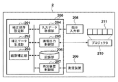
図2に、本実施形態のマルチプロジェクションシステム2における機能の論理構成を示す。情報処理装置200は、補正順序設定部201、補正データ生成部202、画像補正部203、入力データ取得部204、画像出力制御部205、記憶部206、測定装置制御部207を備える。
FIG. 2 shows a logical configuration of functions in the
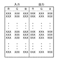
補正順序設定部201は、複数台のプロジェクタに対して補正処理を施す際の順序を設定する。補正データ生成部202は、対象プロジェクタごとに、目標とする色を再現するための補正データを算出する。ここで補正データとは、あるRGB値(以下、入力RGB値)に対応する目標色を、対象のプロジェクタで再現する際に出力するRGB値(以下、出力RGB値)である。補正データ生成部202では図3に示すように、入力RGB値と出力RGB値の対応テーブル(以下、RGB-RGBLUT)を有している。画像補正部203は、記憶部206に記憶されている画像を読み出し、対象プロジェクタごとに出力すべき各RGB値を、それぞれの補正データに応じて更新する。入力データ取得部204は、プロジェクタの配置構成等の情報を指示入力部208から取得する。測定装置制御部207は、測定装置209を制御して各プロジェクタの色再現特性を取得する。測定装置209が取得するプロジェクタの色再現特性としては、例えばRGB各9ステップ、計729色の色票のCIE3刺激値XYZ値を取得する。画像出力制御部205は、記憶部206に記憶された画像を読み込み、プロジェクタ210を制御してスクリーン211へ画像を投影する。
The correction
●投影処理
以下、本実施形態のマルチプロジェクションシステム2における投影処理について、図4のフローチャートを用いて説明する。
Projection Processing Hereinafter, projection processing in the
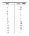
まずS1で入力データ取得部204が、プロジェクタの配置構成に関する情報を取得して記憶部206に記憶する。ここで図5に、本実施形態における全投影領域の構成例を示す。図5において1〜16の各領域は、16台のプロジェクタ個々の投影領域を表している。以下、各領域1〜16への投影が、各プロジェクタ1〜16によるものとして説明する。S1にて取得される配置構成に関する情報とは、プロジェクタの台数、及び図5に示すような投影領域の位置関係(縦横の列数)であり、これらの情報は指示入力部208を介したユーザ指示により入力される。具体的には、画像出力制御部205がプロジェクタ210を制御して図6に示すようなUIを投影し、ユーザが該投影に応じて各パラメータを入力する。図6の1001はプロジェクタ台数の入力エリア、1002は行数および列数の入力エリアであり、これらの入力後に表示ボタン1003が押下されると、ウインドウ1005に配置構成が自動的に表示される。ユーザが表示される配置構成を確認して保存ボタン1004を押下すると、配置構成に関する情報が取得される。
First, in
次にS2で測定装置制御部207が、プロジェクタ1〜16を識別する番号iを1に初期化して記憶部206に記憶する。そしてS3で画像出力制御部205がプロジェクタ210を制御して、カラーチャートの画像(以下、チャート画像)をスクリーン211へ投影する。図7に、投影されるチャート画像の構成例を示す。図7に示す矩形領域は、RGB各9ステップ、計729色の各色票によって構成され、当該チャート画像は予め記憶部206に記憶されているものとする。そしてS4で測定装置制御部207が、測定装置209を制御してi番のプロジェクタで投影されたチャート画像を測定し、該プロジェクタの色再現特性を取得する。ここで測定装置209は2次元測定器であり、1度の測定によって図7に示すチャート画像内の全色票についての色再現特性を取得可能である。ここで取得したプロジェクタの色再現特性は、記憶部206に記憶される。図8に、色再現特性のデータ形式例を示す。図8に示すようにS4で取得される色再現特性とは、RGB各9ステップ、計729色の色票に対応したCIE三刺激XYZ値である。そしてS5で測定装置制御部207が、全てのプロジェクタに対してS3〜S4による色再現特性取得処理が実行されたか否かを判定し、実行されていないプロジェクタがある場合はS6へ、全プロジェクタについて実行されていた場合はS7へ処理を移行する。ここで全てのプロジェクタとは16台のプロジェクタを指し(N=16)、記憶部206に保持されたiの値との比較によって、全プロジェクタについての処理の終了判定を行う。そしてS6では測定装置制御部207がiの値をインクリメントして記憶部206に記憶する。
Next, in S2, the measurement
以上、S1〜S6の処理によって全プロジェクタについての色再現特性が取得され、次に、各プロジェクタに対する画像補正処理が行われる。 As described above, the color reproduction characteristics for all projectors are acquired by the processing of S1 to S6, and then the image correction processing for each projector is performed.
まずS7で補正順序設定部201が、プロジェクタの補正順序を設定して記憶部206に記憶する。ここで図5に、プロジェクタの補正順序の設定例を示す。全投影領域の中心を基準位置Cとして、基準位置Cからの距離が近い投影領域に対応するプロジェクタの順に、自動的に補正順位のナンバリングを行う。図5の例ではまず、基準位置Cに近いプロジェクタ6,7,10,11が1番目の補正順位となる。そして、プロジェクタ2,3,5,9,8,12,14,15が2番目、プロジェクタ1,4,13,16が3番目の補正順位となる。
First, in step S7, the correction
次にS8で画像出力制御部205が、プロジェクタの補正順位(1〜3番目)を識別する番号jを1に初期化して、記憶部206に記憶する。そしてS9で補正データ生成部202が、補正順位jのプロジェクタに対する補正データを生成し、記憶部206に記憶する。ここで補正データとは、上記図3に示すようなRGB-RGBLUTである。なお、補正データ生成処理の詳細については後述する。
Next, in S8, the image
そしてS10で画像補正部203が、記憶部206からS9で生成した各プロジェクタの補正データを読み込み、補正データに基づいて各画像を補正する。補正後の画像は記憶部206に記憶されるものとする。画像の補正はプロジェクタ毎に行われる。まず画像のRGB値を読み込み、これを入力RGB値とし、次にS9で生成したRGB-RGBLUTを参照して、該入力RGB値に対応する出力RGB値を検索する。ただし、上述したようにRGB-RGBLUTは729色に関する入出力対応表であるため、当該729色に含まれない入力RGB値に対応する出力RGB値ついては、四面体補間などの補間演算によって出力RGB値を算出するものとする。そして最後に、画像のRGB値を出力RGB値に置き換える。
In S10, the
次にS11で画像出力制御部205が、S10で補正した画像を記憶部206から読み込み、プロジェクタ210を制御して補正後の画像をスクリーン211へ投影する。そしてS12で画像出力制御部205が、S7で定めた補正順序における全ての順位について、S9〜S11による投影処理が実行されたか否かを判定し、未処理の順位がある場合はS13へ進み、全て実行されていた場合は処理を終了する。ここで、全ての補正順位とは1〜3の値を指し(M=3)、記憶部206に保持されたjの値との比較によって、全ての補正順位についての処理の終了判定を行う。そしてS13では画像出力制御部205がjの値をインクリメントして記憶部206に記憶する。
In step S11, the image
以上、S7〜S13の処理によって、全プロジェクタについての画像補正処理が終了する。 As described above, the image correction processing for all projectors is completed by the processing of S7 to S13.
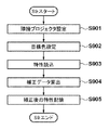
●補正データ生成処理(S9)
以下、上記S9における補正データ生成処理について、図9のフローチャートを用いて詳細に説明する。
Correction data generation process (S9)
Hereinafter, the correction data generation processing in S9 will be described in detail with reference to the flowchart of FIG.
補正データ生成部202は、隣接するプロジェクタの再現色を目標色とし、S7で定めた補正順序に従って順次補正データの生成を行う。S9は、補正順位jであるプロジェクタに対してなされる処理であり、補正順位jに対応するプロジェクタが複数存在する場合には、以下に説明する各処理は該複数のプロジェクタへ同時に適用される。
The correction
まずS901で、補正順位jに対応するプロジェクタに対して隣接プロジェクタを設定する。ここで隣接プロジェクタとは、対象とするプロジェクタの投影領域の上下左右いずれかの領域への投影をなし、且つS9による補正データ生成処理が既に実行済みであるプロジェクタを指す。具体的には、図5に示す各投影領域に対応するプロジェクタについて、該領域における矢印の先の領域に投影しているプロジェクタが、隣接プロジェクタとなる。例えばプロジェクタ13に対しては、プロジェクタ9及びプロジェクタ14を隣接プロジェクタとする。なお、補正順位j=1のプロジェクタ6,7,10,11については、S9が実行済みであるプロジェクタが未だ無いため、隣接プロジェクタは存在しないものと設定される。
First, in S901, an adjacent projector is set for the projector corresponding to the correction order j. Here, the adjacent projector refers to a projector that has performed projection onto any one of the upper, lower, left, and right areas of the projection area of the target projector and has already performed the correction data generation process in S9. Specifically, for the projector corresponding to each projection area shown in FIG. 5, the projector that projects onto the area ahead of the arrow in that area is the adjacent projector. For example, for the
次にS902で、補正順位jに対応する各プロジェクタに対して、記憶部206から隣接プロジェクタの色再現特性を読み込み、目標色を設定する。ここで隣接プロジェクタの色再現特性とは、S4で測定装置209を用いて測定した補正前の色再現特性ではなく、後述するS905で補正後の色再現特性を指す。なお、上述したように最初に処理が行われる補正順位(j=1)のプロジェクタ6,7,10,11については補正済みの隣接プロジェクタが存在しない。したがって、先頭の補正順位であるプロジェクタについては、これらプロジェクタの色再現特性(XYZ値)の平均値を目標色として設定する。また、プロジェクタ13のように補正済みの隣接プロジェクタが複数存在する場合には、これら隣接プロジェクタの色再現特性(XYZ値)の平均値を目標色として設定する。
In step S902, for each projector corresponding to the correction order j, the color reproduction characteristics of the adjacent projector are read from the
そしてS903で、補正順位jに対応する各プロジェクタの補正前の色再現特性、すなわちS4で取得したプロジェクタの色再現特性を記憶部206から読み込む。
In S903, the color reproduction characteristics before correction of each projector corresponding to the correction order j, that is, the color reproduction characteristics of the projector acquired in S4 are read from the
そしてS904で、S902で設定した目標色及びS903で読み込んだ補正前の色再現特性から、補正データ(RGB-RGBLUT)を生成する。まず、729色RGB値に対応するプロジェクタの補正前のXYZ値及び目標色のXYZ値を、CIELABへ全て変換する。これにより、入力RGB値と補正前LAB値との対応関係が得られる。次に、入力RGB値と補正前LAB値の対応関係に基づき、目標色であるLAB値(目標LAB値)を再現するRGB値(出力RGB値)を算出する。ただし、入力RGB値と補正前LAB値の対応関係は729色についてのみ記憶されているため、当該729色に含まれない目標LAB値については、四面体補間などの補間演算により出力RGB値を算出するものとする。また、目標LAB値がプロジェクタiの色域外である場合、目標LAB値から最も近い(色差最小となる)色域内のLAB値を再現する出力RGB値を算出する。以上により、入力RGB値と出力RGB値を対応付ける補正データ(RGB-RGBLUT)が作成される。 In S904, correction data (RGB-RGBLUT) is generated from the target color set in S902 and the color reproduction characteristics before correction read in S903. First, the XYZ value before correction of the projector and the XYZ value of the target color corresponding to the 729 color RGB values are all converted to CIELAB. Thereby, a correspondence relationship between the input RGB value and the LAB value before correction is obtained. Next, an RGB value (output RGB value) for reproducing the LAB value (target LAB value) that is the target color is calculated based on the correspondence relationship between the input RGB value and the LAB value before correction. However, since the correspondence between the input RGB value and the LAB value before correction is stored only for 729 colors, the output RGB value is calculated by interpolation such as tetrahedral interpolation for the target LAB value not included in the 729 color It shall be. Further, when the target LAB value is out of the color gamut of the projector i, an output RGB value that reproduces the LAB value in the color gamut closest to the target LAB value (minimum color difference) is calculated. Thus, correction data (RGB-RGBLUT) that associates the input RGB value with the output RGB value is created.
そしてS905で、補正順位jに対応する各プロジェクタに対して、補正後の色再現特性を記憶部206に記憶する。ここで補正後の色再現特性とは、S904で算出した出力RGB値で再現されるXYZ値であり、図8の補正前の色再現特性を示すRGB値とXYZ値の対応テーブルを用いた補間演算によって、出力RGB値が再現するXYZ値を算出した理論値である。
In step S905, the color reproduction characteristics after correction are stored in the
以上説明したように本実施形態では、複数の画像出力装置による出力画像を連結した連結画像を形成する画像処理システム(具体的にはマルチプロジェクションシステム)を制御するために、以下の構成を備える。すなわち、まず複数の画像出力装置のそれぞれの色再現特性を取得する(図4のS1〜S6)。そして、連結画像における基準位置と各出力画像との位置関係に基づき、複数の画像出力装置に対する補正順序を設定する(S7)。そして、該設定された補正順序に従って画像出力装置の色再現特性を補正する(S8〜S13)。この補正の際に、補正対象となる注目画像出力装置に対し、既に色再現特性が補正済みであり、かつ該注目画像出力装置の出力画像に隣接する出力画像を出力する隣接画像出力装置の色再現特性に基づいて、該注目画像出力装置の色再現特性を補正する。 As described above, the present embodiment includes the following configuration in order to control an image processing system (specifically, a multi-projection system) that forms a connected image obtained by connecting output images from a plurality of image output devices. That is, first, the color reproduction characteristics of each of the plurality of image output devices are acquired (S1 to S6 in FIG. 4). Then, based on the positional relationship between the reference position in the connected image and each output image, a correction order for a plurality of image output devices is set (S7). Then, the color reproduction characteristics of the image output device are corrected according to the set correction order (S8 to S13). At the time of this correction, the color of the adjacent image output device that outputs the output image adjacent to the output image of the target image output device that has already been corrected for the color reproduction characteristics for the target image output device to be corrected Based on the reproduction characteristics, the color reproduction characteristics of the target image output device are corrected.
本実施形態によれば、全投影領域の中央位置から外側へ向かって順次、補正済みである隣接プロジェクタの色再現特性に基づいて色補正を施す。これにより、各プロジェクタが表示可能な色域に対する制限を抑えつつ、隣接するプロジェクタ間での色再現のばらつきを抑えることが可能となる。 According to this embodiment, color correction is performed sequentially from the center position of all the projection areas toward the outside based on the color reproduction characteristics of adjacent projectors that have been corrected. This makes it possible to suppress variations in color reproduction between adjacent projectors while suppressing restrictions on the color gamut that can be displayed by each projector.
<第2実施形態>
以下、本発明に係る第2実施形態について説明する。上述した第1実施形態では、全投影領域の中心から外側に向かって伝播する順序で、各プロジェクタの補正処理を行う例を示した。第2実施形態では、基準位置として任意の点を設定し、該基準位置から外側の投影領域に向かって伝播する順序で、対応する各プロジェクタの補正処理を行う例を示す。なお、第2実施形態におけるマルチプロジェクションシステムの構成は第1実施形態と同様であるため、説明を省略する。また、第2実施形態のマルチプロジェクションシステムにおける投影処理も、第1実施形態で示した図4のフローチャートに従う。
<Second Embodiment>
Hereinafter, a second embodiment according to the present invention will be described. In the first embodiment described above, an example in which correction processing of each projector is performed in the order of propagation from the center of all the projection areas toward the outside has been described. In the second embodiment, an example is shown in which an arbitrary point is set as a reference position, and correction processing of each corresponding projector is performed in the order of propagation from the reference position toward the outside projection area. Note that the configuration of the multi-projection system in the second embodiment is the same as that in the first embodiment, and a description thereof will be omitted. Also, the projection processing in the multi-projection system of the second embodiment follows the flowchart of FIG. 4 shown in the first embodiment.
●補正順序設定処理(S7)
以下、上記図4のS7に相当する、第2実施形態での補正順序設定処理について、図10を用いて説明する。上述したように第2実施形態では、基準位置を任意に設定したうえで補正順序を設定する。なお、S7以外の処理については第1実施形態と同様であるため、説明を省略する。
Correction order setting process (S7)
Hereinafter, the correction order setting process in the second embodiment corresponding to S7 in FIG. 4 will be described with reference to FIG. As described above, in the second embodiment, the correction order is set after arbitrarily setting the reference position. Since processes other than S7 are the same as those in the first embodiment, description thereof will be omitted.
第2実施形態のマルチプロジェクションシステムは、図10(a)に示すような投影領域1〜9に対応するプロジェクタ1〜9の計9台のプロジェクタから構成されるとする。また、各投影領域間の距離については、上下左右の隣接する領域との距離を1とする。また、図中の投影領域1と投影領域5のように、斜め方向の位置関係にある投影領域間については距離を2とする。
The multi-projection system of the second embodiment is assumed to be composed of a total of nine projectors, that is,
まず図10(a)に示すように、ユーザが指示入力部208を介して基準位置Aを設定する。この基準位置Aは、図11に示すUIによって指定される。具体的には、図11における基準位置の入力エリア1006に、基準位置とする投影領域番号を入力する。なお、図11において他の入力エリア、ボタンおよびウィンドウ(1001〜1005)については、第1実施形態で図6に示したUIと同様である。図10(a)の例では、プロジェクタ8による投影領域8を基準位置とする。なお、基準位置に対応するプロジェクタ8については目標とする隣接プロジェクタが存在しないため、画像の補正を行わない。
First, as shown in FIG. 10 (a), the user sets the reference position A via the
次に図10(b)に示すように、基準位置からの距離が1である投影領域に対応するプロジェクタ5,7,9について、それぞれの図中矢印先である投影領域8に対応するプロジェクタ8を隣接プロジェクタとして補正を行う。すなわち、プロジェクタ8の色再現特性から目標色を算出して、第1実施形態と同様の色補正を行う。
Next, as shown in FIG. 10 (b), for the
さらに図10(c)に示すように、基準位置からの距離が2である投影領域に対応するプロジェクタ2,4,6について、それぞれの図中矢印先である投影領域に対応する補正済みプロジェクタ2を隣接プロジェクタとして、補正を行う。
Further, as shown in FIG. 10 (c), for the
そして最後に図10(d)に示すように、基準位置からの距離が3である投影領域に対応するプロジェクタ1,3について、それぞれの図中矢印先である投影領域に対応する補正済みプロジェクタを隣接プロジェクタとして、補正を行う。
Finally, as shown in FIG. 10 (d), with respect to the
なお、ここでは基準位置がユーザにより任意に設定される例を示したが、例えばユーザの位置を検出するセンサを用いて、ユーザに最も近い投影領域に対応するプロジェクタを基準位置として自動設定することも可能である。 Here, an example is shown in which the reference position is arbitrarily set by the user. However, for example, by using a sensor that detects the user's position, the projector corresponding to the projection area closest to the user is automatically set as the reference position. Is also possible.
以上説明したように第2実施形態によれば、任意の基準位置を設定することで、ユーザの視点位置優先等、目的に応じた補正順序を設定することができる。 As described above, according to the second embodiment, by setting an arbitrary reference position, it is possible to set a correction order according to the purpose such as priority of the viewpoint position of the user.
<第3実施形態>
以下、本発明に係る第3実施形態について説明する。上述した第1および第2実施形態では、全投影領域において1つの基準位置を設定する例を示した。第3実施形態では、複数の基準位置を設定する例を示す。なお、第3実施形態におけるマルチプロジェクションシステムの構成は第1実施形態と同様であるため、説明を省略する。また、第3実施形態のマルチプロジェクションシステムにおける投影処理も、第1実施形態で示した図4のフローチャートに従う。
<Third embodiment>
The third embodiment according to the present invention will be described below. In the first and second embodiments described above, an example in which one reference position is set in all projection areas has been described. The third embodiment shows an example in which a plurality of reference positions are set. Note that the configuration of the multi-projection system in the third embodiment is the same as that in the first embodiment, and a description thereof will be omitted. Further, the projection processing in the multi-projection system of the third embodiment also follows the flowchart of FIG. 4 shown in the first embodiment.
●補正順序設定処理(S7)
以下、上記図4のS7に相当する、第3実施形態での補正順序設定処理について、図12を用いて説明する。上述したように第3実施形態では、複数の基準位置を設定したうえで補正順序を設定する。なお、S7以外の処理については第1実施形態と同様であるため、説明を省略する。
Correction order setting process (S7)
Hereinafter, the correction order setting process in the third embodiment corresponding to S7 in FIG. 4 will be described with reference to FIG. As described above, in the third embodiment, the correction order is set after setting a plurality of reference positions. Since processes other than S7 are the same as those in the first embodiment, description thereof will be omitted.
第3実施形態のマルチプロジェクションシステムは、図12(a)に示すような投影領域1〜5に対応するプロジェクタ1〜5の計5台のプロジェクタから構成されるとする。また、各投影領域間の距離については、左右の隣接する領域との距離を1とする。
The multi-projection system of the third embodiment is assumed to be composed of a total of five projectors,
まず図12(a)に示すように、ユーザが指示入力部208を介して基準位置AおよびBを設定する。この例では、プロジェクタ1,5による投影領域1,5を基準位置とする。なお、基準位置に対応するプロジェクタ1,5については目標とする隣接プロジェクタが存在しないため、画像の補正を行わない。
First, as shown in FIG. 12A, the user sets the reference positions A and B via the
次に図12(b)に示すように、基準位置からの距離が1である投影領域に対応するプロジェクタ2,4について、それぞれの図中矢印先である投影領域1,5に対応するプロジェクタ1,5を隣接プロジェクタとして補正を行う。すなわち、例えばプロジェクタ2,4のそれぞれに対し、プロジェクタ1,5の色再現特性から目標色を算出して、第1実施形態と同様の色補正を行う。
Next, as shown in FIG. 12 (b), for the
そして最後に図12(c)に示すように、基準位置からの距離が2である投影領域に対応するプロジェクタ3について、図中矢印先である投影領域に対応する補正済みプロジェクタ2,4を隣接プロジェクタとして、補正を行う。
Finally, as shown in FIG. 12 (c), for the
以上説明したように第3実施形態によれば、任意の基準位置を複数設定することで、複数人のユーザの視点位置を優先する際など、多様な目的に応じた補正順序を設定することができる。 As described above, according to the third embodiment, by setting a plurality of arbitrary reference positions, it is possible to set a correction order according to various purposes, such as when giving priority to the viewpoint positions of a plurality of users. it can.
なお、上記第1〜第3実施形態では、上下左右のプロジェクタ間の距離を1とし、距離1のプロジェクタを隣接プロジェクタとする例を示したが、距離の算出方法としては例えばユークリッド距離を用いる等、異なる方法を適用しても良い。
In the first to third embodiments, an example has been described in which the distance between the upper, lower, left, and right projectors is 1, and the projector of the
<第4実施形態>
以下、本発明に係る第4実施形態について説明する。例えば上述した第1実施形態では、全投影領域の中心から外側に向かって伝播するように補正順序を設定する例を示した。第4実施形態では、補正後の輝度低下及びプロジェクタ間の輝度のばらつきについて、複数の補正順序に従って補正を適用した際の結果予測及び評価値を算出し、該評価値に基づいて最適な補正順序を設定する例を示す。なお、第4実施形態におけるマルチプロジェクションシステムの構成は第1実施形態と同様であるが、図13に示すような投影領域1〜5に対応するプロジェクタ1〜5の計5台のプロジェクタから構成されるとする。また、第4実施形態のマルチプロジェクションシステムにおける投影処理も、第1実施形態で示した図4のフローチャートに従う。
<Fourth embodiment>
The fourth embodiment according to the present invention will be described below. For example, in the first embodiment described above, the example in which the correction order is set so as to propagate from the center of all the projection areas toward the outside has been described. In the fourth embodiment, a predicted result and an evaluation value are calculated when correction is applied according to a plurality of correction orders for luminance reduction after correction and luminance variations between projectors, and an optimal correction order is calculated based on the evaluation values. An example of setting Note that the configuration of the multi-projection system in the fourth embodiment is the same as that of the first embodiment, but is configured by a total of five projectors, that is, the
●補正順序設定処理(S7)
以下、上記図4のS7に相当する、第4実施形態での補正順序設定処理について、図14のフローチャートを用いて説明する。上述したように第4実施形態では、予測される補正後の評価値に基づいて補正順序を設定する。なお、S7以外の処理については第1実施形態と同様であるため、説明を省略する。
Correction order setting process (S7)
Hereinafter, the correction order setting process in the fourth embodiment corresponding to S7 in FIG. 4 will be described with reference to the flowchart in FIG. As described above, in the fourth embodiment, the correction order is set based on the predicted evaluation value after correction. Since processes other than S7 are the same as those in the first embodiment, description thereof will be omitted.
図14に示すように補正順序設定部201は、まずS701で、全てのプロジェクタ1〜5に対して順序付けの初期設定を行い、設定された順序を記憶部206に記憶する。ここでは、プロジェクタ1、2、3、4、5の順序を初期設定したとする。そしてS702で、プロジェクタの補正順位(1〜M,M=5)を識別する番号jを1に初期化して記憶部206に記憶する。そしてS703で、補正順位jに対応するプロジェクタについて補正データを生成する。この補正データ生成処理については、上記図4のS9と同様であるため、ここでは説明を省略する。当該処理によって、補正順位jに対応するプロジェクタの補正データ及び補正後の色再現特性が記憶部206に記憶される。そしてS704で、全ての補正順位(1〜M)について、S703による補正データ生成処理が実行されたか否かを判定する。未処理の補正順位がある場合はS705でjの値をインクリメントして記憶部206に記憶し、全て実行されていた場合はS706へ移行する。
As shown in FIG. 14, the correction
S706では、記憶部206から各プロジェクタの補正後の色再現特性を読み込み、上記補正順序で補正処理を実行した際の評価値Pを以下の評価式(1)に従って算出し、記憶部206に記憶する。
In S706, the corrected color reproduction characteristics of each projector are read from the
P=1/(k1・ΣdL+k2・ΣdS) ・・・(1)
式(1)におけるΣdLは、補正後の隣接プロジェクタ間における白色輝度の差の総和を示す。すなわち、全プロジェクタ1〜5であれば、プロジェクタ1,2間の輝度差、プロジェクタ2,3間の輝度差、プロジェクタ3,4間の輝度差、プロジェクタ4,5間の輝度差の和を指す。このΣdLの値が小さいほど、補正後の隣接プロジェクタ間におけるばらつきが小さい旨が示される。
P = 1 / (k1 / ΣdL + k2 / ΣdS) (1)
ΣdL in equation (1) represents the sum of the differences in white luminance between adjacent projectors after correction. That is, for all
また、式(1)におけるΣdSは、各プロジェクタの補正前後の白色輝度の差の総和を示す。すなわち、全プロジェクタ1〜5であれば、各プロジェクタ1〜5について、補正前の白色輝度と補正後の白色輝度との輝度差を算出し、該5台分の各輝度差の総和を求めたものである。このΣdsの値が小さいほど、補正処理による輝度低下(制限)が小さい旨が示される。
In addition, ΣdS in Expression (1) indicates the total sum of the differences in white luminance before and after correction of each projector. That is, for all
また、式(1)におけるk1,k2は、指示入力部208を介してユーザが指示した定数値を示す。したがって、ユーザが定数k1,k2を調整することで、ΣdLとΣdsのいずれを優先するかの調整が可能となる。すなわち評価値Pは、隣接するプロジェクタによる出力画像間での輝度のばらつき抑制の度合いと、全てのプロジェクタの出力画像における輝度(コントラスト)の総和維持の度合いについて、いずれを優先するかを重み付けによって制御可能である。したがって、目的に応じた評価値Pを算出することができる。
Further, k1 and k2 in the expression (1) indicate constant values designated by the user via the
次にS707で、全ての補正順序について、評価値を算出したか否かを判定する。例えば、本実施形態のマルチプロジェクションシステムは5台のプロジェクタから構成されており、これらを1台ずつ順次補正するとすれば該5台に対して計120通りの補正順序が設定可能である。したがってS707では、この全120通りの補正順序に対する評価値の算出が実行されたか否かを判定する。未処理の補正順序があればS708へ移行し、処理対象となる補正順序を、評価値算出が行われていない補正順序へ変更して記憶部206に記憶した後、S702に戻る。一方、全ての補正順序に対する評価値算出が実行されていればS709へ移行し、記憶部206より各補正順序に対応する評価値を読み込み、評価値が最大となる補正順序を記憶部206に設定する。
In step S707, it is determined whether evaluation values have been calculated for all correction orders. For example, the multi-projection system of the present embodiment includes five projectors. If these are sequentially corrected one by one, a total of 120 correction orders can be set for the five projectors. Therefore, in S707, it is determined whether or not evaluation values have been calculated for all 120 correction orders. If there is an unprocessed correction order, the process proceeds to S708, the correction order to be processed is changed to a correction order for which evaluation value calculation has not been performed and stored in the
第4実施形態では、以上のように設定された補正順序に従って、上記図4におけるS7以降の処理を行う。 In the fourth embodiment, the processes after S7 in FIG. 4 are performed according to the correction order set as described above.
以上説明したように第4実施形態によれば、複数のプロジェクタにおける複数の補正順序に対する評価値を設け、該評価値に応じて最適な補正順序を設定する。これにより、プロジェクタが表示可能な色域の低下、または隣接プロジェクタ間のばらつき、のいずれの抑制を優先するかを、ユーザが目的に応じて任意に設定した補正処理が可能となる。 As described above, according to the fourth embodiment, evaluation values for a plurality of correction orders in a plurality of projectors are provided, and an optimal correction order is set according to the evaluation values. Accordingly, it is possible to perform a correction process in which the user arbitrarily sets, according to the purpose, whether to give priority to the reduction of the color gamut that can be displayed by the projector or the variation between adjacent projectors.
なお、第4実施形態では評価式(1)によって評価値を定義したが、評価値はこの例に限定されず、例えば輝度のみでなく、補正前後の色域体積の差等を加味した評価値を用いても良い。 Although the evaluation value is defined by the evaluation formula (1) in the fourth embodiment, the evaluation value is not limited to this example, for example, an evaluation value that considers not only the luminance but also a difference in color gamut volume before and after the correction. May be used.
<第5実施形態>
以下、本発明に係る第5実施形態について説明する。上述した第1乃至第4実施形態では、基準位置や評価値等に応じてプロジェクタの補正順序を自動設定する例を示したが、第5実施形態ではユーザによる補正順序設定を可能とする例を示す。なお、第5実施形態におけるマルチプロジェクションシステムの構成は第1実施形態と同様に、図5に示すような投影領域1〜16に対応するプロジェクタ1〜16の計16台のプロジェクタから構成されるとする。また、第5実施形態のマルチプロジェクションシステムにおける投影処理も、第1実施形態で示した図4のフローチャートに従う。
<Fifth embodiment>
Hereinafter, a fifth embodiment according to the present invention will be described. In the first to fourth embodiments described above, the example in which the correction order of the projector is automatically set according to the reference position, the evaluation value, and the like has been described. However, in the fifth embodiment, the correction order can be set by the user. Show. As in the first embodiment, the multi-projection system in the fifth embodiment includes a total of 16 projectors, that is,
●補正順序設定処理(S7)
以下、上記図4のS7に相当する、第5実施形態での補正順序設定処理について、図15を用いて説明する。図15は、S7において画像出力制御部205がプロジェクタ210を制御して投影するUI例を示す。なお、S7以外の処理については第1実施形態と同様であるため、説明を省略する。
Correction order setting process (S7)
Hereinafter, the correction order setting process in the fifth embodiment corresponding to S7 in FIG. 4 will be described with reference to FIG. FIG. 15 shows an example of a UI that is projected by the image
図15において、参照ボタン1007を押下することによって、図16に示すようなデータ形式によって補正順序を指示するファイルが選択される。予めユーザが当該ファイルを作成しておくことで、N台のプロジェクタに対して1〜Nの順序全てを任意に設定することが可能となる。なお、図15における他の各入力エリア及びボタン1001〜1005については、第1実施形態で図6に示したUIと同様であるため、説明を省略する。
In FIG. 15, when a
第5実施形態では、上記UIにより選択されたファイルに記載の補正順序に従って、上記図4におけるS7以降の処理を行う。 In the fifth embodiment, the processes after S7 in FIG. 4 are performed according to the correction order described in the file selected by the UI.
以上説明したように第5実施形態によれば、ユーザによって予め設定された補正順序を入力することで、任意の補正順序による補正処理を行うことが可能となる。 As described above, according to the fifth embodiment, it is possible to perform correction processing in an arbitrary correction order by inputting a correction order preset by the user.
<その他の実施形態>
以下、本発明における他の実施形態を示す。
<Other embodiments>
Hereinafter, other embodiments of the present invention will be described.
上記各実施形態においては、補正前のプロジェクタの色再現特性を、マルチプロジェクションシステム2における測定装置209を用いて取得する例を示したが、色再現特性の取得方法はこの例に限定されない。例えば、測定装置209に代えてデジタルカメラ等の撮影装置を備え、チャート画像内の各色票を撮影したRGB値を変換して測定XYZを取得しても良い。この撮影RGB値→測定XYZ値の変換には、例えば以下の式(2),(3),(4)の何れかを用いることができる。なお各式において、Rp,Gp,Bpは撮影RGB値、Xp,Yp,Zpは測定XYZ値を示す。
In each of the above-described embodiments, an example in which the color reproduction characteristics of the projector before correction are acquired using the
|Xp| |Rp|
|Yp|= M1・|Gp| ・・・(2)
|Zp| |Bp|
| Rp |
| Gp |
|Xp| | Bp |
|Yp|= M2・|Rp・Rp| ・・・(3)
|Zp| |Gp・Gp|
|Bp・Bp|
| 1 |
式(2),(3)におけるM1,M2はそれぞれ、撮影値を測色値へ変換するための3×3,3×7のマトリクスを示し、当該マトリクスは記憶部206等に予め記憶されているものとする。なお、マトリクスの次数は前記2種に制限されず、例えば、3×10などのマトリクスであっても良い。
| Xp | | Rp |
| Yp | = M1 ・ | Gp | (2)
| Zp | | Bp |
| Rp |
| Gp |
| Xp | | Bp |
| Yp | = M2 ・ | Rp ・ Rp | (3)
| Zp | | Gp ・ Gp |
| Bp ・ Bp |
| 1 |
M1 and M2 in the equations (2) and (3) respectively indicate 3 × 3 and 3 × 7 matrices for converting photographed values to colorimetric values, and the matrices are stored in advance in the
また、マルチプロジェクションシステムに測定装置または撮影装置を含まず、予め測定した、または撮影値からの変換により得られた測定値を記憶部206に記憶しておき、これを読み出すようにしても良い。
In addition, the multi-projection system may not include a measurement device or an imaging device, and a measurement value measured in advance or obtained by conversion from an imaging value may be stored in the
また、上記各実施形態において、補正後のプロジェクタの色再現特性についは補間演算による理論値を用いる例を示したが、補正後に再度チャート画像の投影及び測定を行って実測値を取得するようにしても良い。 In each of the above-described embodiments, an example in which a theoretical value by interpolation calculation is used for the color reproduction characteristics of the projector after correction has been shown. However, after correction, the actual measurement value is obtained by projecting and measuring the chart image again. May be.
また、上記各実施形態において、プロジェクタの色再現特性を、RGB各9ステップ729色に対するXYZ値として説明したが、色再現特性はこの例に限定されない。例えばXYZ値を変換したCIELAB等であっても良いし、色数についてもRGB5ステップ125色や、RGB17ステップ4913色であっても良い。
In each of the above embodiments, the color reproduction characteristics of the projector have been described as XYZ values for 9 steps of 729 RGB colors, but the color reproduction characteristics are not limited to this example. For example, CIELAB or the like obtained by converting the XYZ values may be used, and the number of colors may be 125 colors of
また、本発明は、上述した実施形態の機能(例えば、上記の各部の処理を各工程に対応させたフローチャートにより示される処理)を実現するソフトウェアのプログラムコードを記録した記憶媒体を、システム或いは装置に供給することによっても実現できる。この場合、そのシステム或いは装置のコンピュータ(又はCPUやMPU)が、コンピュータが読み取り可能に記憶媒体に格納されたプログラムコードを読み出し実行することにより、上述した実施形態の機能を実現する。 Further, the present invention provides a storage medium storing a program code of software for realizing the functions of the above-described embodiments (for example, processing shown by a flowchart in which processing of each unit described above is associated with each process), a system or an apparatus It can also be realized by supplying to. In this case, the function of the above-described embodiment is realized by the computer (or CPU or MPU) of the system or apparatus reading and executing the program code stored in the storage medium so that the computer can read it.
Claims (10)
前記複数の画像出力装置のそれぞれの色再現特性を取得する特性取得手段と、
前記連結画像における基準位置と各出力画像との位置関係に基づき、前記複数の画像出力装置に対する補正順序を設定する補正順序設定手段と、
前記補正順序設定手段で設定された補正順序に従って前記画像出力装置の色再現特性を補正する補正手段と、を有し、
前記補正手段は、補正対象となる注目画像出力装置に対し、既に色再現特性が補正済みであり、かつ該注目画像出力装置の出力画像に隣接する出力画像を出力する隣接画像出力装置の色再現特性に基づいて、該注目画像出力装置の色再現特性を補正し、
前記補正手段は、前記注目画像出力装置に対し、前記隣接画像出力装置の色再現特性に基づいて補正の目標色を設定して、該注目画像出力装置の色再現特性を該目標色を用いて補正し、
前記補正順序設定手段は、1つの補正順位に対して複数の画像出力装置を設定し、
前記補正手段は、前記注目画像出力装置に先頭の補正順位が設定されていた場合に、同じく先頭の補正順位が設定された画像出力装置の色再現特性に基づいて、該注目画像出力装置に対する前記目標色を設定する
ことを特徴とする画像処理装置。 An image processing device that controls an image processing system that forms a connected image obtained by connecting output images from a plurality of image output devices,
Characteristic acquisition means for acquiring the respective color reproduction characteristics of the plurality of image output devices;
Correction order setting means for setting a correction order for the plurality of image output devices based on a positional relationship between a reference position in the connected image and each output image;
Correction means for correcting the color reproduction characteristics of the image output device according to the correction order set by the correction order setting means,
The correction unit corrects the color reproduction characteristics of the target image output device to be corrected, and reproduces the color of the adjacent image output device that outputs an output image adjacent to the output image of the target image output device. Based on the characteristics, correct the color reproduction characteristics of the image output device of interest ,
The correction means sets a target color for correction based on the color reproduction characteristic of the adjacent image output apparatus for the target image output apparatus, and uses the target color for the color reproduction characteristic of the target image output apparatus. Correct,
The correction order setting means sets a plurality of image output devices for one correction order,
When the leading correction order is set in the attention image output device, the correction unit is configured to perform the correction for the attention image output device based on the color reproduction characteristics of the image output device in which the leading correction order is set. An image processing apparatus characterized by setting a target color .
前記特性取得手段が、前記複数の画像出力装置のそれぞれの色再現特性を取得し、
前記補正順序設定手段が、前記連結画像における基準位置と各出力画像との位置関係に基づき、前記複数の画像出力装置に対する補正順序を設定し、
前記補正手段が、該設定された補正順序に従って前記画像出力装置の色再現特性を補正する際に、補正対象となる注目画像出力装置に対し、既に色再現特性が補正済みであり、かつ該注目画像出力装置の出力画像に隣接する出力画像を出力する隣接画像出力装置の色再現特性に基づいて、該注目画像出力装置の色再現特性を補正し、
前記補正手段が、前記注目画像出力装置に対し、前記隣接画像出力装置の色再現特性に基づいて補正の目標色を設定して、該注目画像出力装置の色再現特性を該目標色を用いて補正し、
前記補正順序設定手段が、1つの補正順位に対して複数の画像出力装置を設定し、
前記補正手段が、前記注目画像出力装置に先頭の補正順位が設定されていた場合に、同じく先頭の補正順位が設定された画像出力装置の色再現特性に基づいて、該注目画像出力装置に対する前記目標色を設定する
ことを特徴とする画像処理方法。 An image processing method in an image processing apparatus for controlling an image processing system that forms a connected image obtained by connecting output images from a plurality of image output apparatuses, having characteristic acquisition means, correction order setting means, and correction means,
The characteristic acquisition means acquires the color reproduction characteristics of each of the plurality of image output devices;
The correction order setting means sets a correction order for the plurality of image output devices based on a positional relationship between a reference position in the connected image and each output image;
When the correction means corrects the color reproduction characteristics of the image output apparatus according to the set correction order, the color reproduction characteristics have already been corrected for the target image output apparatus to be corrected, and Based on the color reproduction characteristics of the adjacent image output apparatus that outputs an output image adjacent to the output image of the image output apparatus, the color reproduction characteristics of the target image output apparatus are corrected ,
The correction means sets a target color for correction based on the color reproduction characteristic of the adjacent image output device for the target image output device, and uses the target color as the color reproduction characteristic of the target image output device. Correct,
The correction order setting means sets a plurality of image output devices for one correction order,
When the correction means has a leading correction order set in the attention image output apparatus, the correction means is configured to perform the correction for the attention image output apparatus based on the color reproduction characteristics of the image output apparatus in which the leading correction order is set. An image processing method characterized by setting a target color .
Priority Applications (1)
| Application Number | Priority Date | Filing Date | Title |
|---|---|---|---|
| JP2013076456A JP6172998B2 (en) | 2013-04-01 | 2013-04-01 | Image processing apparatus and image processing method |
Applications Claiming Priority (1)
| Application Number | Priority Date | Filing Date | Title |
|---|---|---|---|
| JP2013076456A JP6172998B2 (en) | 2013-04-01 | 2013-04-01 | Image processing apparatus and image processing method |
Publications (2)
| Publication Number | Publication Date |
|---|---|
| JP2014204173A JP2014204173A (en) | 2014-10-27 |
| JP6172998B2 true JP6172998B2 (en) | 2017-08-02 |
Family
ID=52354282
Family Applications (1)
| Application Number | Title | Priority Date | Filing Date |
|---|---|---|---|
| JP2013076456A Active JP6172998B2 (en) | 2013-04-01 | 2013-04-01 | Image processing apparatus and image processing method |
Country Status (1)
| Country | Link |
|---|---|
| JP (1) | JP6172998B2 (en) |
Families Citing this family (5)
| Publication number | Priority date | Publication date | Assignee | Title |
|---|---|---|---|---|
| JP2016085435A (en) * | 2014-10-29 | 2016-05-19 | 株式会社リコー | Image processing system |
| JP6665545B2 (en) * | 2016-01-20 | 2020-03-13 | セイコーエプソン株式会社 | Image projection system, projector, and image correction method |
| WO2018135141A1 (en) * | 2017-01-17 | 2018-07-26 | ソニー株式会社 | Information processing device, information processing method, and projection system |
| WO2020065792A1 (en) * | 2018-09-26 | 2020-04-02 | Necディスプレイソリューションズ株式会社 | Video reproduction system, video reproduction device, and calibration method for video reproduction system |
| JP6866915B2 (en) * | 2019-11-01 | 2021-04-28 | セイコーエプソン株式会社 | Image projection system and control method of image projection system |
Family Cites Families (6)
| Publication number | Priority date | Publication date | Assignee | Title |
|---|---|---|---|---|
| JP2001092431A (en) * | 1999-09-27 | 2001-04-06 | Fujitsu General Ltd | Screen adjusting method of multidisplay device |
| JP2002214700A (en) * | 2001-01-17 | 2002-07-31 | Hitachi Ltd | Rear projector |
| JP2006251516A (en) * | 2005-03-11 | 2006-09-21 | Pioneer Electronic Corp | Display device and multi-display system |
| JP2009159371A (en) * | 2007-12-27 | 2009-07-16 | Seiko Epson Corp | Device and method for adjusting image, and image display system |
| US8648964B2 (en) * | 2010-11-30 | 2014-02-11 | Nec Corporation | Multi-projection display system and method of adjusting brightness thereof |
| JP5839847B2 (en) * | 2011-06-13 | 2016-01-06 | シャープ株式会社 | Computer-aided calibration execution method and calibration execution system |
-
2013
- 2013-04-01 JP JP2013076456A patent/JP6172998B2/en active Active
Also Published As
| Publication number | Publication date |
|---|---|
| JP2014204173A (en) | 2014-10-27 |
Similar Documents
| Publication | Publication Date | Title |
|---|---|---|
| JP5687608B2 (en) | Image processing apparatus, image processing method, and image processing program | |
| JP6172998B2 (en) | Image processing apparatus and image processing method | |
| JP6035947B2 (en) | Image display device, image display method, and image display program | |
| US8985781B2 (en) | Projector control device and computer-readable recording medium | |
| US10152945B2 (en) | Image processing apparatus capable of performing conversion on input image data for wide dynamic range | |
| JP7327957B2 (en) | Image display system, method and program | |
| JP2005189542A (en) | Display system, display program and display method | |
| JP2008092565A (en) | Color matching method and image capturing device | |
| JP4906658B2 (en) | Color processing apparatus and method | |
| JP6000611B2 (en) | Image processing apparatus and method | |
| US9293113B2 (en) | Image processing apparatus and control method thereof | |
| JP3627103B2 (en) | Large screen display device | |
| JP5523078B2 (en) | Image processing apparatus and image processing method | |
| JP2016010013A (en) | Image processing apparatus and method for the same | |
| JP2006109088A (en) | Geometric correction method in multi-projection system | |
| US9854134B2 (en) | Color processing apparatus and color processing method | |
| JP2020088709A (en) | Image processing apparatus, image processing method and program | |
| JP2015171039A (en) | Color processing apparatus and color processing method | |
| JP6320278B2 (en) | Color processing apparatus and method | |
| JP6420919B2 (en) | Color processing apparatus and method | |
| JP2012113244A (en) | Image processor, image processing method and program | |
| JP2010081051A (en) | Method of converting color, color conversion device, and color conversion program | |
| JP2015222896A (en) | Color adjustment device and color adjustment method | |
| JP2013162462A (en) | Signal processing program, signal processor, and camera | |
| JP2014204203A (en) | Color processing apparatus and color processing method |
Legal Events
| Date | Code | Title | Description |
|---|---|---|---|
| A621 | Written request for application examination |
Free format text: JAPANESE INTERMEDIATE CODE: A621 Effective date: 20160209 |
|
| A977 | Report on retrieval |
Free format text: JAPANESE INTERMEDIATE CODE: A971007 Effective date: 20161024 |
|
| A131 | Notification of reasons for refusal |
Free format text: JAPANESE INTERMEDIATE CODE: A131 Effective date: 20161028 |
|
| A521 | Written amendment |
Free format text: JAPANESE INTERMEDIATE CODE: A523 Effective date: 20161221 |
|
| TRDD | Decision of grant or rejection written | ||
| A01 | Written decision to grant a patent or to grant a registration (utility model) |
Free format text: JAPANESE INTERMEDIATE CODE: A01 Effective date: 20170605 |
|
| A61 | First payment of annual fees (during grant procedure) |
Free format text: JAPANESE INTERMEDIATE CODE: A61 Effective date: 20170704 |
|
| R151 | Written notification of patent or utility model registration |
Ref document number: 6172998 Country of ref document: JP Free format text: JAPANESE INTERMEDIATE CODE: R151 |