JP6170916B2 - Mass spectrometer - Google Patents
Mass spectrometer Download PDFInfo
- Publication number
- JP6170916B2 JP6170916B2 JP2014518577A JP2014518577A JP6170916B2 JP 6170916 B2 JP6170916 B2 JP 6170916B2 JP 2014518577 A JP2014518577 A JP 2014518577A JP 2014518577 A JP2014518577 A JP 2014518577A JP 6170916 B2 JP6170916 B2 JP 6170916B2
- Authority
- JP
- Japan
- Prior art keywords
- plasma
- magnetic field
- aperture
- mass spectrometer
- electrons
- Prior art date
- Legal status (The legal status is an assumption and is not a legal conclusion. Google has not performed a legal analysis and makes no representation as to the accuracy of the status listed.)
- Expired - Fee Related
Links
Images


Classifications
-
- H—ELECTRICITY
- H01—ELECTRIC ELEMENTS
- H01J—ELECTRIC DISCHARGE TUBES OR DISCHARGE LAMPS
- H01J27/00—Ion beam tubes
- H01J27/02—Ion sources; Ion guns
- H01J27/24—Ion sources; Ion guns using photo-ionisation, e.g. using laser beam
-
- H—ELECTRICITY
- H01—ELECTRIC ELEMENTS
- H01J—ELECTRIC DISCHARGE TUBES OR DISCHARGE LAMPS
- H01J49/00—Particle spectrometers or separator tubes
- H01J49/02—Details
- H01J49/10—Ion sources; Ion guns
- H01J49/16—Ion sources; Ion guns using surface ionisation, e.g. field-, thermionic- or photo-emission
- H01J49/161—Ion sources; Ion guns using surface ionisation, e.g. field-, thermionic- or photo-emission using photoionisation, e.g. by laser
- H01J49/162—Direct photo-ionisation, e.g. single photon or multi-photon ionisation
Landscapes
- Physics & Mathematics (AREA)
- Optics & Photonics (AREA)
- Chemical & Material Sciences (AREA)
- Engineering & Computer Science (AREA)
- Combustion & Propulsion (AREA)
- Plasma & Fusion (AREA)
- Analytical Chemistry (AREA)
- Electron Tubes For Measurement (AREA)
- Other Investigation Or Analysis Of Materials By Electrical Means (AREA)
- Analysing Materials By The Use Of Radiation (AREA)
Description
ソフトイオン化および光開裂などの光化学の応用を介して未知のガスの組成の検査を促進するために、電磁エネルギを使用することができる。VUV光子のエネルギ(一般的に6〜124eV)はほとんどの化学種の電子励起およびイオン化エネルギに相応するので、電磁スペクトルの真空紫外(VUV)領域は、これらの応用において特に有用である。真空紫外(VUV)光は一般的に、10〜200ナノメートルの領域の波長を有する光と定義される。 Electromagnetic energy can be used to facilitate the examination of unknown gas compositions through photochemical applications such as soft ionization and photocleavage. The vacuum ultraviolet (VUV) region of the electromagnetic spectrum is particularly useful in these applications because the energy of VUV photons (generally 6-124 eV) corresponds to the electronic excitation and ionization energy of most species. Vacuum ultraviolet (VUV) light is generally defined as light having a wavelength in the region of 10-200 nanometers.
ほとんどの既存のシステムは、例えば共鳴ランプ、周波数逓倍レーザ、またはシンクロトロンを用いて、暴露される領域から離れてVUV光を発生させること、および典型的にはVUV光が窓を通過することにより、この光が関心領域に到達するように試みることを含む。しかし、この波長範囲の窓材および屈折光学は稀であるか存在しないので、VUV光を方向付けあるいは集光させることは往々にして非現実的である。使用される窓は典型的にはこの波長スペクトルの光の大部分を吸収し、かつ反射光学系は、完全にクリーンとは言えない環境では汚染されることがあり得る。加えて、レーザおよびシンクロトロンは極めて高価になることがあり得、かつ大量の電力および空間を必要とすることがあり得る。 Most existing systems use, for example, a resonant lamp, a frequency doubling laser, or synchrotron to generate VUV light away from the exposed area, and typically by passing the VUV light through a window. , Attempting to reach this region of interest. However, since window materials and refractive optics in this wavelength range are rare or nonexistent, it is often impractical to direct or condense VUV light. The windows used typically absorb most of the light in this wavelength spectrum, and reflective optics can be contaminated in less than clean environments. In addition, lasers and synchrotrons can be very expensive and can require large amounts of power and space.
いわゆる「窓なし」光イオン化装置(「イオン化装置」)は、光スペクトルのより大きい部分を試料に入射させる。しかし、公知の窓なしイオン化装置では、プラズマの光が通過することが望ましいアパーチャ中を、プラズマの陽イオン(「プラズマイオン」)およびプラズマの電子(「プラズマ電子」)が移動することができる。イオン化領域におけるプラズマイオンの存在は、結果的に試料の分析物イオンとピーク干渉し、最終的に関心対象の分析物イオンの検出の信頼性を低下させ得る。プラズマ電子およびプラズマイオンは、電子衝撃イオン化またはイオン分子電荷移動反応のいずれかを介して、試料の分析物イオンのハードイオン化を制御不能に引き起こすおそれがあり、望ましくない。 So-called “windowless” photoionization devices (“ionization devices”) cause a larger portion of the light spectrum to be incident on the sample. However, in known windowless ionizers, plasma cations (“plasma ions”) and plasma electrons (“plasma electrons”) can move through an aperture in which it is desirable for plasma light to pass. The presence of plasma ions in the ionization region can result in peak interference with the analyte ions of the sample and ultimately reduce the reliability of detection of the analyte ions of interest. Plasma electrons and plasma ions can uncontrollably cause hard ionization of analyte ions in the sample, either through electron impact ionization or ionic molecular charge transfer reactions, which is undesirable.
したがって、必要とされるのは、VUV光を発生させかつVUV光を関心領域に送達する、より優れたシステムおよび方法である。 Therefore, what is needed is a better system and method for generating VUV light and delivering VUV light to a region of interest.
代表的実施形態では、イオン化装置は、プラズマを発生させるように構成されたプラズマ源を備える。プラズマは光、プラズマイオン、およびプラズマ電子を含む。プラズマ源は、光の少なくとも一部がアパーチャを通過してガス試料に入射するように配置されたアパーチャを含む。イオン化装置はさらに、イオン化領域と、電界を確立するように構成された複数の電極を含むプラズマ偏向装置とを備え、ここで電界は、プラズマイオンがイオン化領域に入ることを実質的に防止する。 In an exemplary embodiment, the ionizer includes a plasma source configured to generate a plasma. Plasma includes light, plasma ions, and plasma electrons. The plasma source includes an aperture arranged such that at least a portion of the light passes through the aperture and enters the gas sample. The ionizer further includes an ionization region and a plasma deflection device that includes a plurality of electrodes configured to establish an electric field, wherein the electric field substantially prevents plasma ions from entering the ionization region.
別の代表的実施形態では、試料ガスを励起光に暴露させる方法を開示する。該方法は、光、プラズマイオン、およびプラズマ電子を含むプラズマを発生させるステップと、プラズマからの光の少なくとも一部分を、アパーチャを介してイオン化領域内に通すステップと、ガス試料がイオン化領域を通過するステップと、プラズマイオンがイオン化領域に入ることを実質的に防止するように電界を発生させるステップとを含む。 In another exemplary embodiment, a method for exposing a sample gas to excitation light is disclosed. The method includes generating a plasma including light, plasma ions, and plasma electrons, passing at least a portion of the light from the plasma through an aperture into the ionization region, and a gas sample passing through the ionization region. And generating an electric field so as to substantially prevent plasma ions from entering the ionization region.
別の代表的実施形態では、イオン化装置は、入口端および出口端を有し、入口端がガス試料を受け取るように構成されたチャネルと、光、プラズマイオン、およびプラズマ電子を発生させるように構成されたプラズマ源であって、光の少なくとも一部がアパーチャを通過して、チャネルの出口端から放出されたガス試料に入射するように配置された、アパーチャを含むプラズマ源と、電界を確立してプラズマイオンを誘導するように構成された複数の電極とを備える。電界は、プラズマイオンがアパーチャを通り抜けることを実質的に防止する。イオン化装置は、磁界を確立してプラズマ電子を誘導するように構成された磁石を備える。磁界は、プラズマのプラズマ電子がアパーチャを通り抜けることを実質的に防止し、電界および磁界は直交する。 In another exemplary embodiment, the ionizer has an inlet end and an outlet end, and the inlet end is configured to generate light, plasma ions, and plasma electrons with a channel configured to receive a gas sample. An electric field with a plasma source comprising an aperture arranged to impinge at least a portion of the light through the aperture and into the gas sample emitted from the outlet end of the channel. And a plurality of electrodes configured to induce plasma ions. The electric field substantially prevents plasma ions from passing through the aperture. The ionizer includes a magnet configured to establish a magnetic field and induce plasma electrons. The magnetic field substantially prevents the plasma electrons of the plasma from passing through the aperture, and the electric and magnetic fields are orthogonal.
代表的実施形態は、以下の詳細な説明を添付の図面に照らして読むと、最もよく理解される。様々な特徴は必ずしも一定の縮尺では描かれていないことを強調しておく。実際、寸法は、説明を分かり易くするために、恣意的に拡大または縮小することがある。該当し実際的である場合、同様の参照番号は同様の要素を示す。 Exemplary embodiments are best understood from the following detailed description when read in light of the accompanying drawings. It is emphasized that the various features are not necessarily drawn to scale. In fact, the dimensions may be arbitrarily expanded or reduced for clarity of explanation. Wherever applicable and practical, like reference numerals indicate like elements.
以下の詳細な説明では、限定ではなく説明を目的として、本教示に係る実施形態の完全な理解をもたらすために、特定の詳細を開示する代表的実施形態を記載する。しかし、本書に開示する特定の詳細から逸脱する本教示に係る他の実施形態が添付の特許請求の範囲内にとどまることは、本開示から利益を得た当業者には明白である。さらに、代表的実施形態の説明を曖昧にしないために、周知の装置および方法の説明は省くことができる。そのような方法および装置は、明らかに本教示の範囲内である。 In the following detailed description, for purposes of explanation and not limitation, exemplary embodiments disclosing specific details are set forth in order to provide a thorough understanding of embodiments according to the present teachings. However, it will be apparent to one skilled in the art having benefited from this disclosure that other embodiments of the present teachings that depart from the specific details disclosed herein remain within the scope of the appended claims. Furthermore, descriptions of well-known devices and methods can be omitted so as not to obscure the description of the representative embodiments. Such methods and apparatus are clearly within the scope of the present teachings.
光化学の応用のためにガス試料に照射するための効果的な戦略は、試料ガスの流れと結合するのに便利な形状に高密度の光を生成することである。以下に記載するのは、所望の波長の光子(例えば真空紫外(VUV)光)を流動するガス試料に効果的に結合することを可能にする、イオン化装置の代表的実施形態である。 An effective strategy for irradiating a gas sample for photochemical applications is to generate a high density of light in a convenient shape to combine with the sample gas flow. Described below is an exemplary embodiment of an ionizer that allows photons of a desired wavelength (eg, vacuum ultraviolet (VUV) light) to be effectively coupled to a flowing gas sample.
代表的実施形態では、プラズマは構造内で生成され、構造内のアパーチャはイオン化領域内の試料イオンに入射する光子(例えばVUV光子)の窓なし放出を可能にする。アパーチャとイオン化領域との間にプラズマ偏向装置が設けられる。プラズマ偏向装置は、アパーチャとイオン化領域との間の領域に静電界を発生させる偏向電極を含む。電界はアパーチャ中を移動するプラズマの陽イオンを(引力または反発力を介して)偏向させ、これらのイオンがイオン化領域に到達することを実質的に防止する。一実施形態では、プラズマ偏向装置はまた、アパーチャとイオン化領域との間の領域に静磁界を発生させる磁石をも含む。静磁界は、電子がイオン化領域に到達することを実質的に防止する。磁界の大きさは、プラズマ電子の運動に影響を及ぼすのに充分大きいが、比較的大きいプラズマイオンの運動に影響を及ぼすほど大きくない。 In an exemplary embodiment, a plasma is generated in the structure, and the aperture in the structure allows windowless emission of photons (eg, VUV photons) incident on sample ions in the ionization region. A plasma deflection device is provided between the aperture and the ionization region. The plasma deflection apparatus includes a deflection electrode that generates an electrostatic field in a region between the aperture and the ionization region. The electric field deflects (via attractive or repulsive forces) the plasma cations moving through the aperture, substantially preventing these ions from reaching the ionization region. In one embodiment, the plasma deflection apparatus also includes a magnet that generates a static magnetic field in a region between the aperture and the ionization region. The static magnetic field substantially prevents electrons from reaching the ionization region. The magnitude of the magnetic field is large enough to affect the movement of plasma electrons, but not so great as to affect the movement of relatively large plasma ions.
磁界は電界に直交するか、あるいは電界と平行に向き付けられる。以下でさらに詳述する通り、磁界が電界に対して直交する場合、アパーチャ中を移動するプラズマ電子は、電界および磁界の両方に直交する方向に、いわゆるEXB(「X」は外積を表す)ドリフト状態に、ドリフトする。磁界の向きは、プラズマ電子がイオン化領域内にドリフトしないように選択される。磁界が電界と平行(または逆平行)に向き付けられる場合、アパーチャ中を移動するプラズマ電子はローレンツ力を受ける。磁界の向きは、プラズマ電子がイオン化領域から遠ざかるように偏向されるように選択される。 The magnetic field is oriented perpendicular to the electric field or parallel to the electric field. As will be described in more detail below, when the magnetic field is orthogonal to the electric field, plasma electrons traveling through the aperture drift in a direction orthogonal to both the electric and magnetic fields, so-called EXB ("X" represents the outer product). Drift into the state. The direction of the magnetic field is selected so that plasma electrons do not drift into the ionization region. When the magnetic field is directed parallel (or antiparallel) to the electric field, plasma electrons moving through the aperture are subjected to Lorentz forces. The direction of the magnetic field is selected so that the plasma electrons are deflected away from the ionization region.
別の代表的実施形態では、プラズマは、半径方向内向きに流動ガス状試料に向けられた光子(例えばVUV光子)の窓なし放出を可能にするアパーチャが、キャビティの内面または内壁に沿って方向付けられるように構築された、トロイド状のキャビティ内で生成される。代表的実施形態では、静電界および静磁界はソースガスからプラズマを形成させる。代表的実施形態では、電界および磁界はイオン化装置内のいずれの場所でも直交する。これは、電界ベクトルおよび磁界ベクトルの外積(EXB)の方向にプラズマ電子のドリフトを引き起こす。EXBドリフトの結果として、プラズマ電子の移動は、一点(一般的に旋回中心と呼ばれる)を中心とする比較的高速の円運動と、イオン化装置の形状に従った円運動中のこの点の比較的低速のドリフトとの重ね合わせになる。対照的に、それらの比較的大きい質量および比較的弱い静磁界の選択のため、プラズマイオンはEXBドリフトによって著しく影響されず、むしろ静電界内で軸線方向に加速される。以下でさらに詳述する通り、代表的実施形態に係る静電界および静磁界の向きおよび大きさは、プラズマイオンおよびプラズマ電子がイオン化装置のイオン化領域内に向かうことを防止するのに役立つ。 In another exemplary embodiment, the plasma is directed along the inner surface or inner wall of the cavity with an aperture that allows windowless emission of photons (eg, VUV photons) directed radially toward the flowing gaseous sample. It is generated in a toroidal cavity constructed to be attached. In an exemplary embodiment, the electrostatic and magnetic fields cause a plasma to form from the source gas. In an exemplary embodiment, the electric and magnetic fields are orthogonal everywhere in the ionizer. This causes a drift of plasma electrons in the direction of the outer product (EXB) of the electric field vector and the magnetic field vector. As a result of EXB drift, the movement of the plasma electrons is relatively high-speed circular motion around a point (commonly referred to as the center of rotation), and the relative movement of this point during circular motion according to the shape of the ionizer. Overlay with slow drift. In contrast, due to the choice of their relatively large mass and relatively weak static magnetic field, the plasma ions are not significantly affected by EXB drift, but rather are accelerated axially within the electrostatic field. As described in further detail below, the direction and magnitude of the electrostatic and magnetic fields according to exemplary embodiments helps to prevent plasma ions and plasma electrons from going into the ionization region of the ionizer.
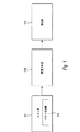
図1は代表的実施形態に係る質量分析計100の簡略概要図を示す。本教示は種々の異なるタイプの質量分析計に適用することができるので、ブロック図はより一般的な形で描かれている。この説明が進むにつれて認識される通り、代表的実施形態の装置および方法は、質量分析計100に関連して使用することができる。このため、質量分析計100は、代表的実施形態の装置および方法の機能および用途についてより包括的な理解を得るのに有用であるが、これらの機能および用途の限定を意図するものではない。質量分析計100はイオン源101、質量分析器102、および検出器103を含む。イオン源101は、ガス試料(図1には図示せず)をイオン化しかつ質量分析器102にイオンを提供するように構成されたイオン化装置104を含む。イオン化装置104の詳細は、以下で代表的実施形態に従って記載する。質量分析計100の他の構成要素は当業者には公知の装置を含むが、代表的実施形態の説明を曖昧にすることを避けるため、詳細には説明しない。例えば、質量分析器102は、とりわけ四重極型質量分析器、イオントラップ型質量分析器、または飛行時間(TOF)型質量分析器を含むことができる。
FIG. 1 shows a simplified schematic diagram of a mass spectrometer 100 according to a representative embodiment. Since the present teachings can be applied to a variety of different types of mass spectrometers, the block diagram is depicted in a more general form. As will be appreciated as this description proceeds, the apparatus and methods of the exemplary embodiments can be used in connection with mass spectrometer 100. Thus, the mass spectrometer 100 is useful for gaining a more comprehensive understanding of the functions and applications of the apparatus and method of the exemplary embodiments, but is not intended to limit these functions and applications. The mass spectrometer 100 includes an
図2Aは、代表的実施形態に係るイオン化装置200の簡略概要図を示す。イオン化装置200は、イオン化装置104と同様にイオン源101内に実現することができる。イオン化装置200は、プラズマ源201、イオン化領域202、およびプラズマ源201とイオン化領域202との間に配置されたプラズマ偏向装置203を備える。以下でさらに詳述する通り、プラズマ偏向装置203は、静電界204を発生させるプラズマイオン偏向電極(図2Aには図示せず)を含む。注目すべきことに、電源(図示せず)がプラズマ偏向電極間に接続され、プラズマ偏向電極間に静電電圧が印加されて静電界が確立される。静電界は、プラズマイオンおよびプラズマ電子をイオン化領域202から遠ざけるように偏向させる(反発させるか引き寄せる)。任意選択的に、静磁界205の源は、プラズマ電子をイオン化領域202から遠ざけるように偏向させるように設けられる。特定の実施形態では、源は永久磁石とすることができ、他の実施形態では、源は電磁石とすることができる。
FIG. 2A shows a simplified schematic diagram of an
プラズマ源201からの光は、プラズマ源201の端部206からアパーチャ(図2Aには図示せず)を介して放出され、イオン化領域202内の試料(図示せず)の分析物分子に入射する。光は分析物分子をイオン化し、それらは次いで質量分析計100の質量分析器102に提供される。代表的実施形態では、プラズマ源201は、James E.Cooley、他の「Microplasma Device with Cavity for Vacuum Ultraviolet Irraditation of Gases and Methods of Making and Using the Same」と称する、本願と同一出願人による米国特許出願第12/613,643号に記載されている通りとすることができる。米国特許出願公開第20110109226号として公開されたこの特許出願の開示内容を特に引用することにより、本明細書の一部をなすものとする。
Light from the
プラズマイオンおよびプラズマ電子は、望ましくないことであるが、プラズマ源201の端部206からアパーチャを介して放出されることができる。上述の通り、プラズマイオンおよびプラズマ電子がイオン化領域202に入ることは望ましくない。代表的実施形態では、端部206から放出されたプラズマイオンは、静電界204によってイオン化領域から遠ざかる方向(図2Aの座標系でy方向)に偏向され、プラズマ電子は静電界204によって反対方向に変向される。
Plasma ions and plasma electrons can be undesirably emitted from the
プラズマ源201の端部206でアパーチャから放出されたプラズマイオンおよびプラズマ電子は、準中性プラズマ様環境を形成することがあり得る。プラズマ偏向装置203の偏向電極のごく近傍におけるそのような準中性プラズマ様環境の形成は、静電界204を遮蔽してプラズマイオンに対するその影響を弱めるように働くことができる。プラズマイオンおよびプラズマ電子がプラズマ偏向装置203の偏向電極に印加される静電電位を有効に遮蔽する長さが、偏向電極間の距離未満である場合、プラズマイオンがイオン化領域202に到達するのを防止する静電界204の有用性は、望ましくないほど減少する。
Plasma ions and plasma electrons emitted from the
代表的実施形態では、プラズマ偏向装置203内に静電界204が設けられる。プラズマイオンは静電界204によって影響され、イオン化領域から遠ざかるように偏向される。例えば、図2Aに示す静電界204の例示的向きにより、プラズマイオンはy方向に向けられる。プラズマイオンは比較的大きく、静磁界205の大きさは、プラズマイオンの運動が静磁界205によって著しく影響されないように選択される。しかし、プラズマ電子はEXBドリフトにさらされ、図2Aに示す座標系のz方向(すなわちページの平面外)に偏向される。このため、図2Aに示すプラズマ偏向装置203における静電界204および静磁界205の印加は、プラズマイオンおよびプラズマ電子の分離を可能にし、それによってプラズマ源201の端部206における準中性プラズマ様環境の形成を防止し、最終的にプラズマイオンおよびプラズマ電子のイオン化領域202から遠ざかる偏向の改善を可能にする。
In the exemplary embodiment, an
図2Bは、別の代表的実施形態に係るイオン化装置200の簡略概要図を示す。イオン化装置200は、イオン化装置104と同様にイオン源101内に実現することができる。イオン化装置200は、プラズマ源201、イオン化領域202、およびプラズマ源とイオン化領域との間に配置されたプラズマ偏向装置203を備える。プラズマ偏向装置203はプラズマイオン偏向電極(図示せず)を含む。以下でさらに詳述する通り、プラズマ偏向装置203は、静電界204を発生させるプラズマイオン偏向電極(図2Bには図示せず)を含む。注目すべきことに、電源(図示せず)がプラズマ偏向電極間に接続され、プラズマ偏向電極間に静電電圧が印加されて静電界が確立される。静電界は、プラズマイオンおよびプラズマ電子をイオン化領域202から遠ざけるように偏向させる。任意選択的に、静磁界205の源は、プラズマ電子をイオン化領域202から遠ざけるように偏向させるように設けられる。特定の実施形態では、源は永久磁石とすることができ、他の実施形態では、源は電磁石とすることができる。
FIG. 2B shows a simplified schematic diagram of an
現在記載している実施形態では、静電界204および静磁界205は互いに平行に向き付けられる。静電界204および静磁界205は互いに逆平行に向き付けられるように企図される。
In the presently described embodiment, the
プラズマイオンは静電界204によって影響され、イオン化領域から遠ざかるように(再びy方向に)偏向される。静磁界205に直交する速度成分を有するプラズマ電子は、ローレンツ力(q(E+vXB))の磁気成分(qvXB)にさらされる。ここでvは電子の速度、qは電子の電荷、Eは電界、Bは磁界である。磁気成分はx方向のプラズマ電子の運動を有益に減速させる。最終的に、プラズマ源201の端部206から放出されるプラズマ電子のかなりの部分が、プラズマ偏向装置203によってイオン化領域から遠ざかるように偏向される。このため、図2Bに示すプラズマ偏向装置203における静電界204および静磁界205の印加は、プラズマイオンおよびプラズマ電子の分離を可能にし、それによってプラズマ源201の端部206における準中性プラズマ様環境の形成を防止し、最終的にプラズマイオンおよびプラズマ電子のイオン化領域202から遠ざかる偏向を改善する。
Plasma ions are affected by the
図3Aは、代表的実施形態に係るイオン化装置300の断面図を示す。イオン化装置300は、イオン化装置104と同様にイオン源101内に実現することができる。イオン化装置300は対称軸301を中心に配置される。入口302が設けられ、分析物分子を含む試料ガス(図示せず)を受け取るように構成される。試料ガスは入口302で対称軸301と平行な方向に向けられる。
FIG. 3A shows a cross-sectional view of an
導電性であることが有用であるイオン化装置300の様々な構成要素は、ステンレス鋼のような適切な導電性材料から作成される。電気絶縁性であることが要求されるイオン化装置300の様々な構成要素は、高温プラスチック(例えばVespel(登録商標))のような適切な電気絶縁体、または適切な快削性セラミック材(例えばMacor(登録商標)、アルミナ、または窒化ホウ素)から作成される。代表的実施形態の磁石は例証として、当業者には公知の希土類磁石である。
The various components of the
イオン化装置300は、第1プラズマ源303と、任意選択的に第2プラズマ源304とを備える。第1および第2プラズマ源303、304は例証として、上記の引用により本明細書の一部をなすものとする米国特許出願公開第20110109226号に記載されている通りである。注目すべきことに、第2プラズマ源304は第1プラズマ源303に冗長機能をもたらし、その機能についてはこれ以上詳述しない。
The
イオン化装置300は、プラズマ306からの光が透過するアパーチャ(図3Aには図示せず)に隣接して配置された偏向装置305を備える。プラズマからの光は、イオン化領域307で試料ガスに入射する。イオン化後に、分析物イオンはイオン光学系308によって出口309および質量分析器(図3Aには図示せず)に向かって送られる。上述し、かつ本実施形態に関連して以下でさらに詳述する通り、偏向装置305は、静電界および任意選択的に静磁界を提供するように構成される。静電界は一般的に、以下に記載されている偏向電極間に約10Vから100Vの範囲の電圧差を生成することによって確立される。上述の通り、磁界強度は、プラズマ電子を偏向させるが、プラズマ電子より大きい質量を有するプラズマイオンを偏向させないように選択される。例えば静磁界は約5000ガウスである。
The
特定の実施形態では、電界は磁界に直交する。このため、プラズマイオンは静電界によって影響され、イオン化領域307から遠ざかるように偏向される。プラズマ電子はEXBドリフトにさらされ、図3Aに示す座標系のz方向(すなわちページの平面外)に偏向される。
In certain embodiments, the electric field is orthogonal to the magnetic field. For this reason, the plasma ions are affected by the electrostatic field and are deflected away from the
他の実施形態では、静電界は静磁界と平行(または逆平行)である。プラズマイオンは静電界によって影響され、イオン化領域307から遠ざかるように偏向される。静磁界に直交する速度成分を有するプラズマ電子はローレンツ力の磁気成分にさらされ、イオン化領域から遠ざかるように偏向される。
In other embodiments, the electrostatic field is parallel (or antiparallel) to the static magnetic field. Plasma ions are affected by the electrostatic field and are deflected away from the
図3Bは、図3Aに示したイオン化装置300の拡大部分を示す。注目すべきことに、図3Bは偏向装置305を詳細に示す。偏向装置305は第1偏向電極310および第2偏向電極311を含む。特定の実施形態では、第1および第2偏向電極310、311は、第1プラズマ源303および第2プラズマ源304の両方からのプラズマイオンおよびプラズマ電子を偏向させて、プラズマイオンおよびプラズマ電子がイオン化領域307に到達することを実質的に防止する、電界を生成するように配置される。例示的実施形態では、第1および第2偏向電極310、311は、プラズマイオンおよびプラズマ電子がz方向にイオン化領域307内に移動するのを実質的に逸らすように、x次元に向き付けられたそれぞれの電界を確立する。
FIG. 3B shows an enlarged portion of the
偏向装置305は任意選択的に、第1磁石312および第2磁石313を含む。第1および第2磁石312、313は極性が逆であり、半径方向の磁界を生成する。第1および第2磁石312、313は、当業者にとって公知の永久磁石または電磁石を含むことができる。第1および第2偏向電極310、311のように、第1および第2磁石312、313は、第1および第2磁石312、313の各々が第1プラズマ源303および第2プラズマ源304の両方からのプラズマ電子を偏向させるように、対称軸301を中心に環状に配置される。
The
第1プラズマ源303とイオン化領域307との間に第1アパーチャ314が設けられ、第2プラズマ源304とイオン化領域307との間に第2アパーチャ315が配置される。代表的実施形態では、第1および第2アパーチャ314、315は、幅(図示する座標系のz方向)が約600μmであり、高さ(図示する座標系のx方向)が約250μmである。第1および第2偏向電極310、311は(x方向に)約1.0mmだけ分離され、イオン化領域307は(y−z面内に)約3.0mmの半径を有する。構成要素の絶対寸法およびそれらの間隔は、単なる例証にすぎないことに留意されたい。しかし、寸法の尺度は、イオンおよび電子のイオン化領域307から遠ざかる偏向を確実にするために必要な充分な電磁界強度を適切に確保するように制御される。
A
第1および第2アパーチャ314、315は、発生したプラズマからの光による試料ガスの窓なし照射をもたらす。プラズマイオンおよびプラズマ電子は第1および第2アパーチャ314、315を通過し、垂直方向(図3Bの座標系でそれぞれ−y方向およびy方向)に移動することができる。プラズマイオンおよびプラズマ電子が偏向されないと、プラズマイオンおよびプラズマ電子はイオン化領域307に入り、上述の通り試料ガスを汚染する。第1および第2アパーチャ314、315に隣接する領域において、第1および第2偏向電極310、311は、プラズマイオンおよびプラズマ電子をイオン化領域307から遠ざける方向に(すなわち±x方向に)偏向させるために、x方向に静電界を確立するように構成される。有益なことに、第1および第2偏向電極310、311、ならびに第1および第2磁石の組込みを通して、イオン化領域307におけるプラズマイオン電流は、公知のイオン化装置と比較して1000分の1に低減される。
The first and
特定の実施形態では、第1および第2磁石312、313は、第1および第2偏向電極310、311間に確立された静電界の方向に対して直交する静磁界を提供するように構成される。このため、図3Bに示す座標系で、静磁界は−y方向になる。−y方向に(すなわち第1プラズマ源303からイオン化領域307に向かって)移動する電子は、EXBドリフトによって−z方向(ページの平面内)に偏向される。同様に、+y方向に(すなわち第2プラズマ源304からイオン化領域307に向かって)移動する電子は、EXBドリフトによって+z方向(ページの平面外)に偏向される。有益なことに、プラズマイオンおよびプラズマ電子はイオン化領域307から遠ざかるように偏向され、試料ガスの汚染が実質的に防止される。有益なことに、第1および第2偏向電極310、311、ならびに第1および第2磁石312、313の組込みを通して、イオン化領域307におけるプラズマイオン電流およびプラズマ電子電流は各々、公知のイオン化装置と比較して1000分の1に低減される。
In certain embodiments, the first and
特定の実施形態では、第1および第2磁石312、313は、第1および第2偏向電極310、311間に確立される静電界の方向と平行(または逆平行)な静磁界を提供するように構成される。このため、図3Bに示す座標系で、静磁界はx方向になる。−y方向に(すなわち第1プラズマ源303からイオン化領域307に向かって)移動する電子は、ローレンツ力の磁気成分によってz方向(ページの平面外)に偏向される。同様に、+y方向に(すなわち第2プラズマ源304からイオン化領域307に向かって)移動する電子は、ローレンツ力の磁気成分によって+z方向(ページの平面内)に偏向される。有益なことに、第1および第2偏向電極310、311、ならびに第1および第2磁石312、313の組込みを通して、イオン化領域307におけるプラズマイオン電流およびプラズマ電子電流は各々、公知のイオン化装置と比較して1000分の1に低減される。
In certain embodiments, the first and
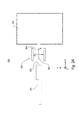
図4Aは、代表的実施形態に係るイオン化装置400の断面図を示す。イオン化装置400は、イオン化装置104と同様にイオン源101内に実現することができる。イオン化装置400は、チャネル402を受容するように構成された筐体401を備える。チャネル402は入口403および出口404を含む。ガス試料405は入口403でもたらされる。導電性であることが有用であるイオン化装置400の様々な構成要素は、ステンレス鋼のような適切な導電性材料から作成される。電気絶縁性であることが要求されるイオン化装置400の様々な構成要素は、高温プラスチック(例えばVespel(登録商標))のような適切な電気絶縁体、または適切な快削性セラミック材(例えばMacor(登録商標)、アルミナ、または窒化ホウ素)から作成される。代表的実施形態の磁石は例証として、当業者には公知の希土類磁石である。
FIG. 4A shows a cross-sectional view of an
プラズマ406は、チャネル402を実質的に包囲するキャビティ407内で生成される。キャビティ407は、構造体の内壁409’に沿ってアパーチャ408を含む構造体409内に形成される。以下でさらに詳述する通り、内壁409’に沿ったアパーチャ408は、プラズマ406内で生成された光子(例えばVUV光子)がチャネル402の出口404でガス試料405に入射し、かつガス試料405の光イオン化を引き起こすことを可能にする。
プラズマ陽極410はキャビティ407の一端に配置され、プラズマ陰極411はキャビティ407の反対側の端に配置される。外側磁石412が筐体401の凹所413に設けられ、キャビティ407を実質的に包囲する。内側磁石414は、図示する通り、チャネル402を実質的に包囲する。注目すべきことに、外側および内側磁石412、414は極性が逆であり、半径方向の磁界を形成する。外側および内側磁石412、414は、当業者にとって公知の永久磁石または電磁石を含むことができる。代表的実施形態では、外側および内側磁石412、414は、2000ガウスから約10000ガウスの範囲の磁界強度をもたらす。
The
任意選択的プラズマ電子偏向電極415がチャネル402の出口404付近に配置される。プラズマ電子偏向電極415は、図4Aに示す通りチャネル402の出口404付近を実質的に包囲する。任意選択的プラズマイオン偏向電極416がチャネルの出口404付近に配置され、チャネル402の出口404とプラズマイオン偏向電極416との間にイオン化領域417が形成される。以下でさらに詳述する通り、プラズマ406を生成するために使用される確立された電界および磁界によって、プラズマイオンおよびプラズマ電子はキャビティ407内に閉じ込められるので、プラズマ電子偏向電極415およびプラズマイオン偏向電極416は省くことができる。代表的実施形態では、約30Vから約120Vの範囲の電圧がプラズマ電子偏向電極415とプラズマイオン偏向電極416との間にもたらされ、それらの間に必要不可欠な静電界が確立される。
An optional plasma
プラズマイオン偏向電極416に隣接してイオン抽出光学系418が設けられる。イオン化されたガス試料419が、イオン化装置400の出口420でもたらされる。質量分析計100において、出口420は質量分析器102に接続される。代表的実施形態では、イオン化領域417および質量分析器102からのイオンの移動を確実にするために、イオン抽出光学系の間に適切な電圧差が維持される。
An ion extraction
イオン化装置400は、本教示の軸線方向を画定する対称軸421を中心に配置される。下記のように、プラズマ陽極410とプラズマ陰極411との間に軸線方向に静電電圧差が確立される。外側および内側磁石412、414によって、図4Aに矢印422で示す通り、半径方向内向きに(すなわち軸線方向に直交して)磁界が確立される。
The
入口ポート(図4Aには図示せず)がキャビティ407に接続され、プラズマ406を発生させるためのソースガス(図示せず)を受け取るように構成される。一部の実施形態では、ソースガスは希ガス、例えばクリプトン、ネオン、アルゴン、またはヘリウムを含む。一部の実施形態では、ソースガスは水素を含む。ソースガスは、ガス試料405に対するイオン化装置400の所望の出力光子波長に対応するガス混合物またはガス組成として選択することができる。ソースガスの適切な選択を通して、プラズマ406の種々の発光波長を選択することができる。例えばヘリウム(He)は58.43nmに共鳴発光線を有し、21.22eVのエネルギを持つ光子を放出する一方、クリプトン(Kr)は116.49nmおよび123.58nmに線を有し、10.64eVおよび10.03eVの対応する光子エネルギを持つ。このようにして発光波長を所望の用途に適切に一致させることができる。このため、フラグメンテーションを減らして大きい分子をイオン化するために、比較的低エネルギの光子を使用することができる。代替的に、分子フラグメンテーションのために比較的高エネルギの光子を使用することができ、あるいは他の化合物をイオン化することなく特定の化合物を選択的にイオン化するように、光子エネルギを選択することができる。
An inlet port (not shown in FIG. 4A) is connected to
プラズマ陽極410およびプラズマ陰極411はエネルギ源(図示せず)に接続される。エネルギ源は、プラズマを発生させかつ維持するために、RFまたはマイクロ波のような適切な周波数のDC電圧、パルス電圧、または振動信号の形で、エネルギをソースガスにもたらすように構成される。
代表的実施形態では、キャビティ407は例証としてトロイドである。動作中、プラズマ406を発生させるためにソースガスが入口ポート(図4Aには図示せず)に供給される。静電電圧、DC電圧、パルス電圧、および/または適切な周波数(例えばRFまたはマイクロ波)の振動電圧のいずれかが、プラズマ陽極410とプラズマ陰極411との間に送達される。結果的に生じる電界は、実質的にキャビティ407内に閉じ込められたプラズマ406内に放電を維持する。キャビティ407の内壁409’に沿ったアパーチャ408は、チャネル402の入口403と出口404との間に圧力差を維持することができるように、プラズマ406からのソースガスの流動を制限しながら、半径方向内向きの窓なし光(例えばVUV)放出を可能にする。さらに、軸線方向に確立された電界は、プラズマ406のプラズマイオンをキャビティ407内(すなわちプラズマ陽極410とプラズマ陰極411との間)に閉じ込めるのを助ける。
In the exemplary embodiment, the
磁界は半径方向内向きになる(すなわち、矢印422で示される通り、対称軸421に直交する)。静電界および静磁界のこの直交配向はEXBドリフトを生成し、プラズマ406の電子の移動は、旋回中心周りの比較的高速の円運動と、EXB方向(すなわち、矢印423で示される通り、対称軸421を中心とする回転方向)のこの点の比較的低速のドリフトとの重ね合わせになる。少し表現を変えると、プラズマ406のプラズマ電子の運動は、対称軸421を中心に円弧状の略一定速度の方位角運動となる。磁界は、対称軸421を中心とするEXBドリフト軌道上のプラズマ406の電子を捕捉する。プラズマ電子はキャビティ407内に導入されたソースガスをイオン化し、プラズマ406を維持するのを助ける。プラズマ電子によって生成されたプラズマイオンは、比較的弱い磁界によって著しく影響されず、むしろプラズマ陽極410とプラズマ陰極411との間の軸線方向静電気力によって加速され、プラズマ406をさらに維持する。
The magnetic field is radially inward (ie, orthogonal to the axis of
以下でさらに詳述する通り、プラズマの生成に加えて、プラズマ陽極410およびプラズマ陰極411は、プラズマイオンおよびプラズマ電子をキャビティ407に閉じ込め、プラズマイオンおよびプラズマ電子がアパーチャ408を介してイオン化領域417内に移動するのを実質的に防止するのに役立つ。同様に、プラズマの生成に加えて、内側および外側磁石414、412は、電子をキャビティに閉じ込め、プラズマ電子がアパーチャを介してイオン化領域内に移動するのを実質的に防止するのに役立つ。このため、プラズマ陽極410およびプラズマ陰極411は内側および外側磁石414、412と共に、代表的実施形態に係る偏向装置として機能する。
As will be described in more detail below, in addition to generating plasma,
イオン化装置400の直交する電界および磁界の相対的向きは、プラズマ406を生成しかつ維持するように機能するだけでなく、プラズマ406の電子およびイオンをキャビティ407内に実質的に閉じ込めるように機能する。アパーチャ408には窓が無いので、イオンおよび電子がアパーチャ408を介して、イオン化領域417内およびチャネル402内に漏出する可能性がある。そのようなイオンおよび電子は試料ガス/イオンを汚染し、最終的に質量分析計100による測定が不正確になるおそれがある。有益なことに、上述の通り、プラズマ406のイオンはプラズマ陽極410とプラズマ陰極411との間の電界によって強力に誘導され、アパーチャ408から出て行くことが実質的に防止される。プラズマ406の電子は、対称軸を中心に回転するEXBドリフトに閉じ込められ、同様にアパーチャ408を介して出て行くことが実質的に防止される。
The relative orientation of the orthogonal electric and magnetic fields of the
図4Bは、図4Aに示したイオン化装置400の部分分解組立部分断面図を示す。イオン化装置400は、チャネル402を受容するように構成された筐体401を備える。筐体401およびチャネル402はステンレス鋼のような導電性材料を含む。
FIG. 4B shows a partial exploded assembly partial cross-sectional view of the
ガス試料405は入口403に提供される。プラズマ406は、チャネル402を実質的に包囲する構造体409のキャビティ407内で生成される。構造体409は例証として、キャビティ407における電界が軸線方向(すなわち対称軸421と平行)になることを確実にするように、プラズマイオンおよびプラズマ電子を偏向させるために発生させた電界からかつイオン抽出光学系418からキャビティ407を分離する、電気絶縁体(例えば高温プラスチックまたは適切な快削性セラミック材)である。内壁409’に沿ったアパーチャ408は、プラズマ406内に生成された光子(例えばVUV光子)がチャネル402の出口404でガス試料405に入射し、かつガス試料405の光イオン化を引き起こすことを可能にする。
A
図4Bに示す通り、キャビティ407は例証としてトロイドである。動作中、キャビティ407内でプラズマを発生させるためにソースガスが入口ポート(図4Bには図示せず)に供給される。静電電圧、DC電圧、パルス電圧、および/または適切な周波数(例えばRFまたはマイクロ波)の振動電圧のいずれかが、プラズマ陽極410とプラズマ陰極411との間に送達される。結果的に生じる電界は、実質的にキャビティ407内部に閉じ込められたプラズマ406内の放電を維持する。キャビティ407のアパーチャ408は、チャネル402の入口403と出口404との間に圧力差を維持することができるように、プラズマ406からのソースガスの流動を制限しながら、半径方向内向き(矢印422の方向)の窓なし光(例えばVUV)放出を可能にする。さらに、軸線方向に確立された電界は、プラズマ406のプラズマイオンをキャビティ407内(すなわちプラズマ陽極410とプラズマ陰極411との間)に閉じ込めるのを助ける。
As shown in FIG. 4B, the
磁界は半径方向内向きになる(すなわち、矢印422で示される通り、対称軸421に直交する)。静電界および静磁界のこの直交配向はEXBドリフトを生成し、プラズマ406の電子の移動は、旋回中心周りの比較的高速の円運動と、EXB方向(すなわち、矢印423で示される通り、対称軸421を中心とする回転方向)のこの点の比較的低速のドリフトとの重ね合わせになる。少し表現を変えると、プラズマ406のプラズマ電子の運動は、対称軸421を中心に円弧状の略一定速度の方位角運動となる。磁界は、対称軸421を中心とするEXBドリフト軌道上のプラズマ406の電子を捕捉する。プラズマ電子はキャビティ407内に導入されたソースガスをイオン化し、プラズマ406を維持するのを助ける。プラズマ電子によって生成されたプラズマイオンは、比較的弱い磁界によって著しく影響されず、むしろプラズマ陽極410とプラズマ陰極411との間の軸線方向静電気力によって加速され、プラズマ406をさらに維持する。
The magnetic field is radially inward (ie, orthogonal to the axis of
任意選択的プラズマ電子偏向電極415がチャネル402の出口404付近に配置される。プラズマ電子偏向電極415は、図4Bに示す通りチャネル402の出口404付近を実質的に包囲する。任意選択的プラズマイオン偏向電極416がチャネル402の出口404付近に配置され、チャネル402の出口404とプラズマイオン偏向電極416との間にイオン化領域417が形成される。上述の通り、プラズマ406を生成するために使用される確立された電界および磁界によって、プラズマイオンおよびプラズマ電子はキャビティ407内に閉じ込められるので、プラズマ電子偏向電極415およびプラズマイオン偏向電極416は省くことができる。
An optional plasma
図5は、代表的実施形態に係る試料ガスを励起光に暴露する方法500のフローチャートを示す。方法500は、図1〜図4Bに関連して説明した代表的実施形態に係るイオン化装置を使用して実現することができる。501で、該方法は、光、プラズマイオン、およびプラズマ電子を含むプラズマを発生させるステップを含む。502で、該方法は、プラズマからの光の少なくとも一部分を、アパーチャを介してイオン化領域に通すステップを含む。503で、該方法は、ガス試料がイオン化領域を通過するステップを含む。504で、該方法は、プラズマイオンがイオン化領域に入るのを実質的に防止するように、電界を発生させるステップを含む。 FIG. 5 shows a flowchart of a method 500 for exposing a sample gas to excitation light according to an exemplary embodiment. The method 500 can be implemented using the ionizer according to the exemplary embodiment described in connection with FIGS. At 501, the method includes generating a plasma that includes light, plasma ions, and plasma electrons. At 502, the method includes passing at least a portion of the light from the plasma through the aperture to the ionization region. At 503, the method includes passing a gas sample through the ionization region. At 504, the method includes generating an electric field so as to substantially prevent plasma ions from entering the ionization region.
本書に代表的実施形態を開示したが、本教示に従う多くの変形例が可能であり、かつ添付する特許請求の範囲内であることを、当業者は理解する。したがって本発明は、添付の特許請求の範囲による場合を除き、限定されない。
[実施形態例]
[実施形態1]
光、プラズマイオン、およびプラズマ電子を含むプラズマを発生させるように構成されたプラズマ源であって、光の少なくとも一部がアパーチャを通過しかつガス試料に入射するように配置されたアパーチャを含むプラズマ源と、
イオン化領域と、
電界を確立するように構成された複数の電極を含むプラズマ偏向装置であって、前記プラズマイオンが前記イオン化領域に入るのを前記電界が実質的に防止するようにしたプラズマ偏向装置と
を備えるイオン化装置。
[実施形態2]
前記プラズマ偏向装置がさらに、磁界を確立するように構成された磁石を含み、前記プラズマの電子が前記イオン化領域に入るのを前記磁界が実質的に防止する、実施形態1に記載のイオン化装置。
[実施形態3]
前記電界および前記磁界が実質的に直交する、実施形態2に記載のイオン化装置。
[実施形態4]
前記電界および前記磁界が実質的に平行である、実施形態2に記載のイオン化装置。
[実施形態5]
前記電界および前記磁界が実質的に逆平行である、実施形態2に記載のイオン化装置。
[実施形態6]
前記電界が軸線方向に向き付けられ、かつ前記磁界が半径方向に向き付けられた、実施形態2に記載のイオン化装置。
[実施形態7]
前記電界および前記磁界が半径方向に向き付けられた、実施形態2に記載のイオン化装置。
[実施形態8]
質量分析器と、検出器と、イオン源とを備えた質量分析計であって、前記イオン源が実施形態1に記載のイオン化装置を含む、質量分析計。
[実施形態9]
試料ガスを励起光に暴露させる方法であって、
光、プラズマイオン、およびプラズマ電子を含むプラズマを発生させるステップと、
前記プラズマからの前記光の少なくとも一部分を、アパーチャを介してイオン化領域に通すステップと、
ガス試料がイオン化領域を通過するステップと、
前記プラズマイオンが前記イオン化領域に入るのを実質的に防止するように電界を発生させるステップと
を含む方法。
[実施形態10]
前記プラズマ電子が前記イオン化領域に入るのを実質的に防止するように磁界を発生させるステップをさらに含む、実施形態9に記載の方法。
[実施形態11]
前記電界および前記磁界が実質的に直交する、実施形態10に記載の方法。
[実施形態12]
前記電界および前記磁界が実質的に平行である、実施形態10に記載の方法。
[実施形態13]
前記電界および前記磁界が実質的に逆平行である、実施形態10に記載の方法。
[実施形態14]
前記電界が軸線方向に向き付けられ、かつ前記磁界が半径方向に向き付けられた、実施形態10に記載の方法。
[実施形態15]
入口端および出口端を有し、前記入口端がガス試料を受け取るように構成されて成るチャネルと、
光、プラズマイオン、およびプラズマ電子を発生するように構成されたプラズマ源であって、前記光の少なくとも一部がアパーチャを通過しかつ前記チャネルの前記出口端から放出された前記ガス試料に入射するように配置されたアパーチャを含むプラズマ源と、
電界を確立して前記プラズマイオンを誘導するように構成された複数の電極であって、前記プラズマイオンが前記アパーチャから出るのを前記電界が実質的に防止するようにした複数の電極と、
磁界を確立して前記プラズマ電子を誘導するように構成された磁石であって、前記プラズマ電子が前記アパーチャから出るのを前記磁界が実質的に防止し、かつ前記電界および前記磁界が直交するようにした磁石と
を備えたイオン化装置。
[実施形態16]
前記磁石が、前記プラズマ源を実質的に包囲する外側磁石と、前記チャネルを実質的に包囲する内側磁石とを含む、実施形態15に記載のイオン化装置。
[実施形態17]
前記電界が軸線方向に向き付けられ、かつ前記磁界が半径方向に向き付けられた、実施形態15に記載のイオン化装置。
[実施形態18]
前記アパーチャと前記チャネルとの間に配置され、前記アパーチャを通過したプラズマイオンを引き寄せるかあるいは反発するように構成された、プラズマイオン偏向電極をさらに備える、実施形態15に記載のイオン化装置。
[実施形態19]
前記アパーチャと前記チャネルとの間に配置され、前記アパーチャを通過したプラズマ電子を引き寄せるかあるいは反発するように構成された、プラズマ電子偏向電極をさらに備える、実施形態15に記載のイオン化装置。
[実施形態20]
質量分析器と、検出器と、イオン源とを備えた質量分析計であって、前記イオン源が実施形態15に記載のイオン化装置を含む、質量分析計。
While representative embodiments have been disclosed herein, those skilled in the art will appreciate that many variations are possible in accordance with the present teachings and are within the scope of the appended claims. Accordingly, the invention is not limited except as by the appended claims.
[Example Embodiment]
[Embodiment 1]
A plasma source configured to generate a plasma including light, plasma ions, and plasma electrons, the plasma including an aperture disposed such that at least a portion of the light passes through the aperture and is incident on the gas sample The source,
An ionization region;
A plasma deflection apparatus including a plurality of electrodes configured to establish an electric field, wherein the electric field substantially prevents the plasma ions from entering the ionization region;
An ionizer comprising:
[Embodiment 2]
The ionization apparatus according to embodiment 1, wherein the plasma deflection apparatus further includes a magnet configured to establish a magnetic field, and the magnetic field substantially prevents electrons of the plasma from entering the ionization region.
[Embodiment 3]
The ionization apparatus according to embodiment 2, wherein the electric field and the magnetic field are substantially orthogonal.
[Embodiment 4]
The ionization apparatus according to embodiment 2, wherein the electric field and the magnetic field are substantially parallel.
[Embodiment 5]
The ionization apparatus according to embodiment 2, wherein the electric field and the magnetic field are substantially antiparallel.
[Embodiment 6]
The ionization apparatus according to embodiment 2, wherein the electric field is directed in an axial direction and the magnetic field is directed in a radial direction.
[Embodiment 7]
The ionization apparatus according to embodiment 2, wherein the electric field and the magnetic field are directed in a radial direction.
[Embodiment 8]
A mass spectrometer comprising a mass analyzer, a detector, and an ion source, wherein the ion source includes the ionization apparatus according to the first embodiment.
[Embodiment 9]
A method of exposing a sample gas to excitation light,
Generating a plasma comprising light, plasma ions, and plasma electrons;
Passing at least a portion of the light from the plasma through an aperture to an ionization region;
Passing a gas sample through the ionization region;
Generating an electric field so as to substantially prevent the plasma ions from entering the ionization region;
Including methods.
[Embodiment 10]
10. The method of embodiment 9, further comprising generating a magnetic field so as to substantially prevent the plasma electrons from entering the ionization region.
[Embodiment 11]
The method of embodiment 10, wherein the electric field and the magnetic field are substantially orthogonal.
[Embodiment 12]
The method of embodiment 10, wherein the electric field and the magnetic field are substantially parallel.
[Embodiment 13]
Embodiment 11. The method of embodiment 10 wherein the electric field and the magnetic field are substantially antiparallel.
[Embodiment 14]
The method of embodiment 10, wherein the electric field is directed in an axial direction and the magnetic field is directed in a radial direction.
[Embodiment 15]
A channel having an inlet end and an outlet end, the inlet end configured to receive a gas sample;
A plasma source configured to generate light, plasma ions, and plasma electrons, wherein at least a portion of the light passes through an aperture and is incident on the gas sample emitted from the outlet end of the channel A plasma source including an aperture arranged in a
A plurality of electrodes configured to establish an electric field to induce the plasma ions, the plurality of electrodes substantially preventing the plasma ions from exiting the aperture;
A magnet configured to establish a magnetic field to induce the plasma electrons, wherein the magnetic field substantially prevents the plasma electrons from exiting the aperture, and the electric field and the magnetic field are orthogonal. With magnet
An ionization apparatus comprising:
[Embodiment 16]
16. The ionization apparatus according to embodiment 15, wherein the magnet includes an outer magnet that substantially surrounds the plasma source and an inner magnet that substantially surrounds the channel.
[Embodiment 17]
Embodiment 16. The ionization device according to embodiment 15, wherein the electric field is directed in an axial direction and the magnetic field is directed in a radial direction.
[Embodiment 18]
Embodiment 16. The ionization device according to embodiment 15, further comprising a plasma ion deflection electrode disposed between the aperture and the channel and configured to attract or repel plasma ions that have passed through the aperture.
[Embodiment 19]
Embodiment 16 The ionization apparatus according to embodiment 15, further comprising a plasma electron deflection electrode disposed between the aperture and the channel and configured to attract or repel plasma electrons that have passed through the aperture.
[Embodiment 20]
A mass spectrometer comprising a mass analyzer, a detector, and an ion source, wherein the ion source includes the ionization device according to embodiment 15.
Claims (12)
光、プラズマ(306)イオン、およびプラズマ(306)電子を含むプラズマ(306)を発生させるように構成されたプラズマ源(201)であって、光の少なくとも一部がアパーチャ(408)を通過しかつガス試料(405)に入射するように配置されたアパーチャ(408)を含むプラズマ源(201)と、
イオン化領域(202)と、
電界を確立するように構成された複数の電極を含むプラズマ偏向装置であって、前記プラズマ(306)イオンが前記イオン化領域(202)に入るのを前記電界が実質的に防止するようにしたプラズマ偏向装置(203)と
を備える、
質量分析計(100)。 A mass spectrometer including a mass analyzer (102), a detector (103), and an ion source (101), wherein the ion source (101) includes an ionizer (104), and the ionizer ( 104)
A plasma source (201) configured to generate a plasma (306) comprising light, plasma (306) ions, and plasma (306) electrons, wherein at least a portion of the light passes through the aperture (408). And a plasma source (201) including an aperture (408) arranged to be incident on the gas sample (405);
An ionization region (202);
A plasma deflection apparatus including a plurality of electrodes configured to establish an electric field, wherein the electric field substantially prevents the plasma (306) ions from entering the ionization region (202). A deflection device (203),
Mass spectrometer (100).
入口端および出口端を有し、前記入口端がガス試料を受け取るように構成されて成るチャネルと、
光、プラズマイオン、およびプラズマ電子を発生するように構成されたプラズマ源であって、該プラズマ源は、トロイド状のキャビティを形成する構造体と、該構造体の内壁に沿って配置されたアパーチャとを備え、前記光の少なくとも一部が該アパーチャを通過しかつ前記チャネルの前記出口端から放出された前記ガス試料に入射するように配置された、プラズマ源と、
電界を確立して前記プラズマイオンを誘導するように構成された複数の電極であって、前記プラズマイオンが前記アパーチャから出るのを前記電界が実質的に防止するようにした複数の電極と、
磁界を確立して前記プラズマ電子を誘導するように構成された磁石であって、前記プラズマ電子が前記アパーチャから出るのを前記磁界が実質的に防止し、かつ前記電界および前記磁界が直交するようにした磁石と
を備えたイオン化装置を含む、質量分析計。 A mass spectrometer comprising a mass analyzer, a detector, and an ion source, the ion source comprising :
A channel having an inlet end and an outlet end, the inlet end configured to receive a gas sample;
A plasma source configured to generate light, plasma ions, and plasma electrons, the plasma source comprising a structure forming a toroidal cavity and an aperture disposed along the inner wall of the structure A plasma source arranged such that at least a portion of the light passes through the aperture and is incident on the gas sample emitted from the outlet end of the channel;
A plurality of electrodes configured to establish an electric field to induce the plasma ions, the plurality of electrodes substantially preventing the plasma ions from exiting the aperture;
A magnet configured to establish a magnetic field to induce the plasma electrons, wherein the magnetic field substantially prevents the plasma electrons from exiting the aperture, and the electric field and the magnetic field are orthogonal. With magnet
A mass spectrometer comprising an ionizer comprising:
Applications Claiming Priority (3)
| Application Number | Priority Date | Filing Date | Title |
|---|---|---|---|
| US13/170,282 | 2011-06-28 | ||
| US13/170,282 US8563924B2 (en) | 2011-06-28 | 2011-06-28 | Windowless ionization device |
| PCT/US2012/040407 WO2013002954A2 (en) | 2011-06-28 | 2012-06-01 | Windowless ionization device |
Publications (3)
| Publication Number | Publication Date |
|---|---|
| JP2014524111A JP2014524111A (en) | 2014-09-18 |
| JP2014524111A5 JP2014524111A5 (en) | 2015-07-23 |
| JP6170916B2 true JP6170916B2 (en) | 2017-07-26 |
Family
ID=47389601
Family Applications (1)
| Application Number | Title | Priority Date | Filing Date |
|---|---|---|---|
| JP2014518577A Expired - Fee Related JP6170916B2 (en) | 2011-06-28 | 2012-06-01 | Mass spectrometer |
Country Status (5)
| Country | Link |
|---|---|
| US (1) | US8563924B2 (en) |
| EP (1) | EP2727130B1 (en) |
| JP (1) | JP6170916B2 (en) |
| CN (1) | CN103635989A (en) |
| WO (1) | WO2013002954A2 (en) |
Families Citing this family (3)
| Publication number | Priority date | Publication date | Assignee | Title |
|---|---|---|---|---|
| US8410704B1 (en) * | 2011-11-30 | 2013-04-02 | Agilent Technologies, Inc. | Ionization device |
| JP6076838B2 (en) * | 2013-05-31 | 2017-02-08 | 住友重機械イオンテクノロジー株式会社 | Insulation structure and insulation method |
| US9029797B2 (en) | 2013-07-25 | 2015-05-12 | Agilent Technologies, Inc. | Plasma-based photon source, ion source, and related systems and methods |
Family Cites Families (15)
| Publication number | Priority date | Publication date | Assignee | Title |
|---|---|---|---|---|
| US4476392A (en) | 1981-12-28 | 1984-10-09 | Young Robert A | Photoelectron source for use in a gas chromatograph detector and mass spectrometer ion source |
| JPH0713949B2 (en) * | 1986-04-16 | 1995-02-15 | 日本電信電話株式会社 | Photoreaction method and device |
| JP2631650B2 (en) * | 1986-12-05 | 1997-07-16 | アネルバ株式会社 | Vacuum equipment |
| JP3367719B2 (en) | 1993-09-20 | 2003-01-20 | 株式会社日立製作所 | Mass spectrometer and electrostatic lens |
| US20030038236A1 (en) | 1999-10-29 | 2003-02-27 | Russ Charles W. | Atmospheric pressure ion source high pass ion filter |
| US7106438B2 (en) * | 2002-12-12 | 2006-09-12 | Perkinelmer Las, Inc. | ICP-OES and ICP-MS induction current |
| US7217941B2 (en) * | 2003-04-08 | 2007-05-15 | Cymer, Inc. | Systems and methods for deflecting plasma-generated ions to prevent the ions from reaching an internal component of an EUV light source |
| WO2005017943A2 (en) * | 2003-07-17 | 2005-02-24 | Sionex Corporation | Method and apparatus for plasma generation |
| WO2005050172A2 (en) | 2003-11-14 | 2005-06-02 | Indiana University Research And Technology Corporation | Methods and apparatus for mass spectral analysis of peptides and proteins |
| DE102004025841B4 (en) | 2004-05-24 | 2015-07-09 | Bruker Daltonik Gmbh | Method and apparatus for mass spectroscopic analysis of analytes |
| US20120112051A1 (en) * | 2007-06-01 | 2012-05-10 | Jeol Usa, Inc. | Atmospheric Pressure Charge-Exchange Analyte Ionization |
| US8101923B2 (en) | 2007-11-12 | 2012-01-24 | Georgia Tech Research Corporation | System and method for spatially-resolved chemical analysis using microplasma desorption and ionization of a sample |
| US20100032559A1 (en) * | 2008-08-11 | 2010-02-11 | Agilent Technologies, Inc. | Variable energy photoionization device and method for mass spectrometry |
| JP5136300B2 (en) * | 2008-09-02 | 2013-02-06 | 株式会社島津製作所 | Discharge ionization current detector |
| US20110109226A1 (en) * | 2009-11-06 | 2011-05-12 | Agilent Technologies, Inc. | Microplasma device with cavity for vacuum ultraviolet irradiation of gases and methods of making and using the same |
-
2011
- 2011-06-28 US US13/170,282 patent/US8563924B2/en active Active
-
2012
- 2012-06-01 CN CN201280032020.6A patent/CN103635989A/en active Pending
- 2012-06-01 WO PCT/US2012/040407 patent/WO2013002954A2/en active Application Filing
- 2012-06-01 JP JP2014518577A patent/JP6170916B2/en not_active Expired - Fee Related
- 2012-06-01 EP EP12804533.3A patent/EP2727130B1/en not_active Not-in-force
Also Published As
| Publication number | Publication date |
|---|---|
| US8563924B2 (en) | 2013-10-22 |
| EP2727130A4 (en) | 2015-04-08 |
| US20130001416A1 (en) | 2013-01-03 |
| JP2014524111A (en) | 2014-09-18 |
| CN103635989A (en) | 2014-03-12 |
| WO2013002954A2 (en) | 2013-01-03 |
| EP2727130B1 (en) | 2018-02-28 |
| EP2727130A2 (en) | 2014-05-07 |
| WO2013002954A3 (en) | 2013-03-07 |
Similar Documents
| Publication | Publication Date | Title |
|---|---|---|
| US6593570B2 (en) | Ion optic components for mass spectrometers | |
| US10236169B2 (en) | Ionization device with mass spectrometer therewith | |
| US6768120B2 (en) | Focused electron and ion beam systems | |
| TWI648761B (en) | An improved ion source assembly for producing a ribbon ion beam | |
| JP5872541B2 (en) | Improved ion source | |
| JP5302899B2 (en) | Coaxial hybrid radio frequency ion trap mass spectrometer | |
| US20040051038A1 (en) | Ion guide | |
| JP2005527941A (en) | Device for confining plasma in a volume | |
| JP6170916B2 (en) | Mass spectrometer | |
| US9589775B2 (en) | Plasma cleaning for mass spectrometers | |
| Fathi et al. | Magnetic field design for a Penning ion source for a 200 keV electrostatic accelerator | |
| RU2554104C2 (en) | Mass-spectrometer analyser of gas leak detector | |
| Dance et al. | Threshold electron energy-loss spectra for some unsaturated molecules | |
| JP2020518994A (en) | Ion guide device and related method | |
| CN110176385B (en) | High-efficiency ion source for magnetic mass spectrometer | |
| WO2018092271A1 (en) | Ion analyzer | |
| Sámel et al. | Experimental characterisation of atmospheric pressure electron gun | |
| JP2007194094A (en) | Mass spectroscope | |
| RU137653U1 (en) | MASS SPECTROMETRIC ANALYZER OF GAS LEAK DETECTOR | |
| CN209963019U (en) | High-efficiency ion source for magnetic mass spectrometer | |
| JP7315061B2 (en) | Quadrupole mass spectrometer | |
| JP4034304B2 (en) | X-ray generator having an emitter formed on a semiconductor structure | |
| Weis et al. | A nozzle beam source for the production of metastable rare gas atoms | |
| Somacal et al. | Simulations of electron trajectories under the influence of an array of permanent magnets in a compact ion source | |
| JP2006189298A (en) | Gas chromatograph mass spectrometer and reduction method of background using it |
Legal Events
| Date | Code | Title | Description |
|---|---|---|---|
| A521 | Request for written amendment filed |
Free format text: JAPANESE INTERMEDIATE CODE: A523 Effective date: 20150601 |
|
| A621 | Written request for application examination |
Free format text: JAPANESE INTERMEDIATE CODE: A621 Effective date: 20150601 |
|
| A131 | Notification of reasons for refusal |
Free format text: JAPANESE INTERMEDIATE CODE: A131 Effective date: 20160401 |
|
| A521 | Request for written amendment filed |
Free format text: JAPANESE INTERMEDIATE CODE: A523 Effective date: 20160701 |
|
| A131 | Notification of reasons for refusal |
Free format text: JAPANESE INTERMEDIATE CODE: A131 Effective date: 20161013 |
|
| A521 | Request for written amendment filed |
Free format text: JAPANESE INTERMEDIATE CODE: A523 Effective date: 20170113 |
|
| TRDD | Decision of grant or rejection written | ||
| A01 | Written decision to grant a patent or to grant a registration (utility model) |
Free format text: JAPANESE INTERMEDIATE CODE: A01 Effective date: 20170602 |
|
| A61 | First payment of annual fees (during grant procedure) |
Free format text: JAPANESE INTERMEDIATE CODE: A61 Effective date: 20170703 |
|
| R150 | Certificate of patent or registration of utility model |
Ref document number: 6170916 Country of ref document: JP Free format text: JAPANESE INTERMEDIATE CODE: R150 |
|
| R250 | Receipt of annual fees |
Free format text: JAPANESE INTERMEDIATE CODE: R250 |
|
| LAPS | Cancellation because of no payment of annual fees |