JP6166999B2 - Friction stir tool, friction stir welding apparatus, and friction stir welding method - Google Patents
Friction stir tool, friction stir welding apparatus, and friction stir welding method Download PDFInfo
- Publication number
- JP6166999B2 JP6166999B2 JP2013202757A JP2013202757A JP6166999B2 JP 6166999 B2 JP6166999 B2 JP 6166999B2 JP 2013202757 A JP2013202757 A JP 2013202757A JP 2013202757 A JP2013202757 A JP 2013202757A JP 6166999 B2 JP6166999 B2 JP 6166999B2
- Authority
- JP
- Japan
- Prior art keywords
- tool
- metal material
- friction stir
- rotating
- shoulder portion
- Prior art date
- Legal status (The legal status is an assumption and is not a legal conclusion. Google has not performed a legal analysis and makes no representation as to the accuracy of the status listed.)
- Expired - Fee Related
Links
- 238000003756 stirring Methods 0.000 title claims description 242
- 238000003466 welding Methods 0.000 title claims description 113
- 238000000034 method Methods 0.000 title claims description 7
- 239000007769 metal material Substances 0.000 claims description 183
- 239000000523 sample Substances 0.000 claims description 87
- 238000003825 pressing Methods 0.000 claims description 18
- 238000013019 agitation Methods 0.000 claims description 8
- 238000010030 laminating Methods 0.000 claims description 5
- 229910052751 metal Inorganic materials 0.000 description 93
- 239000002184 metal Substances 0.000 description 93
- 238000010586 diagram Methods 0.000 description 24
- 230000000052 comparative effect Effects 0.000 description 21
- 239000000463 material Substances 0.000 description 14
- 230000002093 peripheral effect Effects 0.000 description 11
- 238000009826 distribution Methods 0.000 description 6
- 238000012986 modification Methods 0.000 description 6
- 230000004048 modification Effects 0.000 description 6
- 238000005520 cutting process Methods 0.000 description 3
- 238000003780 insertion Methods 0.000 description 3
- 230000037431 insertion Effects 0.000 description 3
- 238000005304 joining Methods 0.000 description 3
- 230000007423 decrease Effects 0.000 description 2
- 229910000838 Al alloy Inorganic materials 0.000 description 1
- 239000000470 constituent Substances 0.000 description 1
- 230000003247 decreasing effect Effects 0.000 description 1
- 230000002950 deficient Effects 0.000 description 1
- 238000003475 lamination Methods 0.000 description 1
- 230000035515 penetration Effects 0.000 description 1
- 238000005096 rolling process Methods 0.000 description 1
- 238000010008 shearing Methods 0.000 description 1
Images


Description
本発明は、摩擦撹拌接合に用いられる摩擦撹拌工具、摩擦撹拌接合装置及び摩擦撹拌接合方法に関するものである。 The present invention is a friction stir tool for use in friction stir welding, are those related to the friction stir welding apparatus and FSW how.
従来、ボビンツール式の摩擦撹拌接合用工具が知られている(例えば、特許文献1参照)。この摩擦撹拌接合用工具は、上部回転体と、下部回転体と、上部回転体と下部回転体との間で回転する撹拌軸とを有しており、撹拌軸の外周面には、撹拌溝が形成されている。摩擦撹拌接合用工具は、重ね合わせた一対のプレートを上部回転体と下部回転体とで挟み込み、上部回転体、下部回転体及び撹拌軸を回転させることで、撹拌溝により軸方向にプレートの材料を流動させ、一対のプレートを接合する。 Conventionally, a bobbin tool type friction stir welding tool is known (see, for example, Patent Document 1). This friction stir welding tool has an upper rotating body, a lower rotating body, and a stirring shaft that rotates between the upper rotating body and the lower rotating body. A stirring groove is formed on the outer peripheral surface of the stirring shaft. Is formed. The friction stir welding tool sandwiches a pair of stacked plates between an upper rotating body and a lower rotating body, and rotates the upper rotating body, the lower rotating body and the stirring shaft, thereby rotating the material of the plate in the axial direction by the stirring groove. And a pair of plates are joined.
また、ボビンツール式の摩擦撹拌接合用工具ではないが、表側のワークに接する円筒体と、表側のワーク及び裏側のワークに挿入されるプローブとを有する摩擦撹拌接合用工具が知られている(例えば、特許文献2参照)。この摩擦撹拌接合用工具において、プローブには、先端部の右ねじである第1ねじ部と、後端部の左ねじである第2ねじ部とが設けられている。第1ねじ部は、裏側のワークに配置され、第2ねじ部は、表側のワークに配置される。摩擦撹拌接合用工具は、プローブを回転させることで、第1ねじ部により裏側のワークを表側に巻き上げ、第2ねじ部により表側のワークを裏側へ押し下げる。 Further, although it is not a bobbin tool type friction stir welding tool, a friction stir welding tool having a cylindrical body in contact with the front side workpiece and a probe inserted into the front side workpiece and the back side workpiece is known ( For example, see Patent Document 2). In this friction stir welding tool, the probe is provided with a first thread portion that is a right-hand thread at the front end portion and a second thread portion that is a left-hand thread at the rear end portion. The first screw portion is disposed on the back-side workpiece, and the second screw portion is disposed on the front-side workpiece. The friction stir welding tool rotates the probe to wind up the work on the back side to the front side by the first screw part and push the work on the front side to the back side by the second screw part.
特許文献1に記載の摩擦撹拌接合用工具では、摩擦撹拌時において、撹拌溝により軸方向にプレートの材料を流動させることができる。しかしながら、重ね合わせた一対のプレートの界面における撹拌が考慮されていないことから、界面における撹拌を好適に行うことができず、界面における接合の強度が低下する可能性がある。 In the friction stir welding tool described in Patent Literature 1, the material of the plate can be caused to flow in the axial direction by the stirring groove during friction stirring. However, since stirring at the interface between the pair of stacked plates is not taken into consideration, stirring at the interface cannot be suitably performed, and bonding strength at the interface may be reduced.
また、特許文献2に記載の摩擦撹拌接合用工具では、円筒体が回転することにより表側のワークに入熱が行われるが、裏側のワークに入熱が行われず、入熱が不均一となる。その結果として、表側の温度が高く、裏側の温度が低くなる。このため、第1ねじ部により裏側のワークを表側に巻き上げ、第2ねじ部により表側のワークを裏側へ押し下げるものの、温度分布が不均一であることから、ワークの流動が均一とならず、つまり、温度の低い先端側(裏側)のワークよりも、温度の高い後端側(表側)のワークが流動し易いため、界面における撹拌を好適に行うことができず、界面の巻き上がり等が発生することもあり、界面における接合の強度が低下する可能性がある。 Further, in the friction stir welding tool described in Patent Document 2, heat is input to the front side workpiece by rotating the cylindrical body, but heat input is not performed to the back side workpiece, and the heat input is uneven. . As a result, the front side temperature is high and the back side temperature is low. For this reason, although the work on the back side is rolled up to the front side by the first screw part and the work on the front side is pushed down to the back side by the second screw part, the flow of the work is not uniform because the temperature distribution is non-uniform. Since the workpiece on the rear end side (front side) with higher temperature is more likely to flow than the workpiece on the front end side (rear side) with low temperature, stirring at the interface cannot be performed properly, and rolling up of the interface occurs. In some cases, the bonding strength at the interface may be reduced.
そこで、本発明は、積層した一対の金属材の界面における接合を強固なものとすることができる摩擦撹拌工具、摩擦撹拌接合装置及び摩擦撹拌接合方法を提供することを課題とする。 Accordingly, the present invention is a friction stir tool of the bonding at the interface between a pair of metallic material layered can be made firm, and to provide a friction stir welding apparatus and FSW how.
本発明の摩擦撹拌工具は、一方の金属材と他方の金属材とを積層することで界面が形成される一対の金属材に対し、積層方向の一方側に配置される第1回転ツールと、一対の前記金属材を挟んで前記第1回転ツールの反対側となる他方側に配置され、前記第1回転ツールに対向して設けられる第2回転ツールと、を備え、前記第1回転ツールは、一対の前記金属材の一方側の面と接する第1ショルダ部を有する第1ツール本体を、有し、前記第2回転ツールは、一対の前記金属材の他方側の面と接する第2ショルダ部を有する第2ツール本体と、前記第2ツール本体から前記第1回転ツールに向かって突出し、前記第2ツール本体と前記第1ツール本体との間に設けられ、前記第1ショルダ部と前記第2ショルダ部との間に挟まれた一対の前記金属材を撹拌するプローブとを有し、前記プローブは、前記積層方向の一方側の前記金属材と接する接触面に形成され、撹拌した前記金属材を前記界面に向かって流動させる第1撹拌溝と、前記積層方向の他方側の前記接触面に形成され、撹拌した前記金属材を前記界面に向かって流動させる第2撹拌溝と、を含み、前記プローブは、前記第1撹拌溝と前記第2撹拌溝との境界が、前記界面に位置するように形成されることを特徴とする。 The friction stir tool of the present invention is a first rotating tool disposed on one side in the stacking direction with respect to a pair of metal materials in which an interface is formed by stacking one metal material and the other metal material, A second rotating tool disposed on the other side opposite to the first rotating tool across a pair of the metal materials, and provided opposite to the first rotating tool, the first rotating tool comprising: A first tool body having a first shoulder portion in contact with one side surface of the pair of metal materials, and the second rotating tool is in contact with the other surface of the pair of metal materials. A second tool main body having a portion, protruding from the second tool main body toward the first rotating tool, provided between the second tool main body and the first tool main body, the first shoulder portion and the A pair of fronts sandwiched between the second shoulder A first stirring groove that is formed on a contact surface in contact with the metal material on one side in the stacking direction and flows the stirred metal material toward the interface. And a second agitation groove formed on the contact surface on the other side in the laminating direction and flowing the agitated metal material toward the interface, and the probe includes the first agitation groove and the first agitation groove The boundary between the two stirring grooves is formed so as to be located at the interface.
この構成によれば、第1回転ツール及び第2回転ツールを回転させることで、第1ショルダ部及び第2ショルダ部によって一対の金属材の両側に入熱を行いながら、入熱(摩擦熱)により軟化した金属材をプローブにより撹拌することができる。このため、一対の金属材の両側から入熱を加えることで、第1回転ツール側の金属材と第2回転ツール側の金属材との温度をほぼ同じにすることができる。このとき、回転するプローブの第1撹拌溝により撹拌した金属材を、第1ショルダ部側から界面に向かって流動させることができ、また、回転するプローブの第2撹拌溝により撹拌した金属材を、第2ショルダ部側から界面に向かって流動させることができる。これにより、第1撹拌溝及び第2撹拌溝によって流動する金属材は、ほぼ同じような流動性を有し、界面を跨いでバランスよく流動するため、界面における巻き上げを防止しつつ、接合強度を強固にすることができ、界面破断等の接合不良を抑制することができる。 According to this configuration, by rotating the first rotating tool and the second rotating tool, heat input (friction heat) is performed while heat is input to both sides of the pair of metal materials by the first shoulder portion and the second shoulder portion. The metal material softened by the above can be stirred by the probe. For this reason, by applying heat input from both sides of the pair of metal materials, the temperature of the metal material on the first rotating tool side and the metal material on the second rotating tool side can be made substantially the same. At this time, the metal material stirred by the first stirring groove of the rotating probe can flow toward the interface from the first shoulder side, and the metal material stirred by the second stirring groove of the rotating probe can be The second shoulder portion can be made to flow toward the interface. As a result, the metal material that flows through the first stirring groove and the second stirring groove has substantially the same fluidity and flows in a balanced manner across the interface. It can be strengthened, and bonding failures such as interfacial fracture can be suppressed.
また、前記第1撹拌溝は、1本以上の第1ねじ溝で構成され、前記第2撹拌溝は、前記第1ねじ溝の回転方向と逆方向となる1本以上の第2ねじ溝で構成されていることが好ましい。 The first agitation groove is composed of one or more first screw grooves, and the second agitation groove is one or more second screw grooves that are opposite to the rotation direction of the first screw groove. It is preferable to be configured.
この構成によれば、プローブに第1ねじ溝を形成することで、簡易に第1撹拌溝を構成することができ、また、プローブに第2ねじ溝を形成することで、簡易に第2撹拌溝を構成することができる。このとき、第1ねじ溝及び第2ねじ溝を、複数本とすることで、撹拌による金属材の流動を促進することができる。 According to this configuration, the first stirring groove can be easily formed by forming the first screw groove in the probe, and the second stirring can be easily performed by forming the second screw groove in the probe. Grooves can be configured. At this time, the flow of the metal material by stirring can be promoted by using a plurality of first and second screw grooves.
また、前記第1ねじ溝によって形成される第1ねじ山の高さは、前記第1ショルダ部から前記境界に向かうにつれて高くなり、前記第2ねじ溝によって形成される第2ねじ山の高さは、前記第2ショルダ部から前記境界に向かうにつれて高くなることが好ましい。 The height of the first thread formed by the first thread groove increases from the first shoulder toward the boundary, and the height of the second thread formed by the second thread groove. Is preferably higher from the second shoulder portion toward the boundary.
この構成によれば、第1ショルダ部側から界面へ向かう金属材の流動量を減少させることができ、また、第2ショルダ部側から界面へ向かう金属材の流動量を減少させることができる。ここで、撹拌域中央部(界面付近)での金属材の流動量が多すぎると、撹拌域がその部分で幅方向に過度に広がってしまう。この場合、撹拌域が広がった部分には、第1及び第2ショルダ部からの圧力が充分に付与されず、接合不良部が形成されることがある。このため、金属材の流動量を減少させることにより、界面への金属材の過剰な流動によって発生する撹拌域の幅方向の過度な広がりを抑制することができることから、撹拌域の中央部に接合不良部を形成することなく、界面において金属材を好適に撹拌することができる。 According to this configuration, it is possible to reduce the flow amount of the metal material from the first shoulder portion side toward the interface, and it is possible to reduce the flow amount of the metal material toward the interface from the second shoulder portion side. Here, if there is too much flow rate of the metal material in the central part (near the interface) of the stirring zone, the stirring zone will spread excessively in the width direction at that part. In this case, the pressure from the first and second shoulder portions is not sufficiently applied to the portion where the stirring zone is widened, and a poorly bonded portion may be formed. For this reason, by reducing the amount of flow of the metal material, it is possible to suppress the excessive spread in the width direction of the stirring zone caused by the excessive flow of the metal material to the interface. The metal material can be suitably stirred at the interface without forming a defective portion.
また、前記第1ねじ溝は、前記第1ショルダ部と前記境界との間の所定の部位から、前記境界まで設けられ、前記第2ねじ溝は、前記第2ショルダ部と前記境界との間の所定の部位から、前記境界まで設けられていることが好ましい。 The first thread groove is provided from a predetermined portion between the first shoulder part and the boundary to the boundary, and the second thread groove is provided between the second shoulder part and the boundary. It is preferable to be provided from the predetermined part to the boundary.
この構成によれば、第1ショルダ部から第1ショルダ部と境界との間の所定の部位までの間に、第1ねじ溝が形成されないため、第1ショルダ部側から界面へ向かう金属材の流動量を減少させることができる。また、第2ショルダ部から第2ショルダ部と境界との間の所定の部位までの間に、第2ねじ溝が形成されないため、第2ショルダ部側から界面へ向かう金属材の流動量を減少させることができる。このため、界面への金属材の過剰な流動によって発生する撹拌域の幅方向の過度な広がりを抑制することができることから、撹拌域の中央部に接合不良部を形成することなく、界面において金属材を好適に撹拌することができる。 According to this configuration, since the first screw groove is not formed between the first shoulder portion and the predetermined portion between the first shoulder portion and the boundary, the metal material heading from the first shoulder portion side to the interface The amount of flow can be reduced. In addition, since the second thread groove is not formed between the second shoulder portion and the predetermined portion between the second shoulder portion and the boundary, the amount of flow of the metal material from the second shoulder portion side toward the interface is reduced. Can be made. For this reason, since it is possible to suppress the excessive spread in the width direction of the stirring zone caused by the excessive flow of the metal material to the interface, the metal at the interface is formed without forming a poor bonding portion in the central portion of the stirring zone. The material can be suitably stirred.
また、前記第1ねじ溝及び前記第2ねじ溝には、平坦面が形成されていることが好ましい。より好ましくは、複数の平坦面が形成されていることが好ましい。複数の平坦面はプローブの回転軸に対し対称性を有するように配置されていることが好ましい。 Moreover, it is preferable that a flat surface is formed in the first screw groove and the second screw groove. More preferably, a plurality of flat surfaces are formed. The plurality of flat surfaces are preferably arranged so as to have symmetry with respect to the rotation axis of the probe.
この構成によれば、第1ねじ溝及び第2ねじ溝に平坦面を形成することで、第1及び第2ショルダ部側から界面へ向かう金属材の流動量を減少させることができる。このため、界面への金属材の過剰な流動によって発生する撹拌域の幅方向の過度な広がりを抑制することができることから、撹拌域の中央部に接合不良部を形成することなく、界面において金属材を好適に撹拌することができる。 According to this configuration, by forming flat surfaces in the first screw groove and the second screw groove, it is possible to reduce the amount of flow of the metal material from the first and second shoulder portions toward the interface. For this reason, since it is possible to suppress the excessive spread in the width direction of the stirring zone caused by the excessive flow of the metal material to the interface, the metal at the interface is formed without forming a poor bonding portion in the central portion of the stirring zone. The material can be suitably stirred.
また、前記第1ねじ溝と前記第2ねじ溝とは、前記第2回転ツールの回転軸の周方向において、異なる位相となるように形成されることが好ましい。より好ましくは、前記第1ねじ溝と前記第2ねじ溝とは、二つのねじ溝の対称性を維持した状態で異なる位相となるように形成されることが好ましい。 The first screw groove and the second screw groove are preferably formed to have different phases in the circumferential direction of the rotation shaft of the second rotary tool. More preferably, the first screw groove and the second screw groove are preferably formed to have different phases while maintaining symmetry of the two screw grooves.
この構成によれば、例えば、第1ねじ溝と第2ねじ溝とが1本のねじ溝で構成される場合、180°位相を異ならせることで、180°位相が異なる位置において、金属材の流動を発生させることができ、界面における金属材の撹拌性を向上させることができる。なお、第1ねじ溝と第2ねじ溝とが2本のねじ溝で構成される場合、90°位相を異ならせればよい。なお、第1ねじ溝と第2ねじ溝とを、プローブの回転軸に対し対称性を維持した状態で異なる位相となるように形成することで、プローブの回転バランスをとることができる。 According to this configuration, for example, when the first screw groove and the second screw groove are configured by one screw groove, by changing the 180 ° phase, the position of the metal material is different at a position where the 180 ° phase is different. Flow can be generated and the stirrability of the metal material at the interface can be improved. In addition, what is necessary is just to make a 90 degree phase different, when a 1st thread groove and a 2nd thread groove are comprised by two thread grooves. Note that the rotation balance of the probe can be balanced by forming the first screw groove and the second screw groove so as to have different phases while maintaining symmetry with respect to the rotation axis of the probe.
また、前記第1ねじ溝の一部は、前記境界を超えて前記第2ねじ溝側に形成され、前記第2ねじ溝の一部は、前記境界を超えて前記第1ねじ溝側に形成されていることが好ましい。 Further, a part of the first thread groove is formed on the second thread groove side beyond the boundary, and a part of the second thread groove is formed on the first thread groove side beyond the boundary. It is preferable that
この構成によれば、界面を跨いで金属材を流動させやすくすることができるため、界面における金属材の撹拌性を向上させることができる。 According to this configuration, the metal material can be easily flowed across the interface, so that the stirrability of the metal material at the interface can be improved.
また、前記第1回転ツールの回転方向は、前記第2回転ツールの回転方向と逆方向となっていることが好ましい。 Moreover, it is preferable that the rotation direction of the first rotary tool is opposite to the rotation direction of the second rotary tool.
この構成によれば、第1ショルダ部の回転によって形成される金属材の流動と、第2ショルダ部の回転によって形成される金属材の流動とによって、界面において流動する金属材に対しせん断力を発生させることができる。このため、界面における金属材の撹拌性を向上させることができる。さらには、接合を阻害する酸化被膜等の界面の被膜を破壊することができる。 According to this configuration, the shearing force is applied to the metal material flowing at the interface by the flow of the metal material formed by the rotation of the first shoulder portion and the flow of the metal material formed by the rotation of the second shoulder portion. Can be generated. For this reason, the stirrability of the metal material at the interface can be improved. Furthermore, it is possible to destroy an interface film such as an oxide film that inhibits bonding.
また、一対の前記金属材のうち、他方の前記金属材の前記積層方向における厚さが、一方の前記金属材の前記積層方向における厚さに比して厚くなる場合、前記第2回転ツールの回転軸に直交する前記第2ショルダ部の直径は、前記第1回転ツールの回転軸に直交する前記第1ショルダ部の直径に比して大径となり、一対の前記金属材のうち、一方の前記金属材の前記積層方向における厚さが、他方の前記金属材の前記積層方向における厚さに比して厚くなる場合、前記第1回転ツールの回転軸に直交する前記第1ショルダ部の直径は、前記第2回転ツールの回転軸に直交する前記第2ショルダ部の直径に比して大径となることが好ましい。 Further, when the thickness of the other metal material in the stacking direction of the pair of metal materials is larger than the thickness of the one metal material in the stacking direction, the second rotating tool The diameter of the second shoulder portion orthogonal to the rotation axis is larger than the diameter of the first shoulder portion orthogonal to the rotation axis of the first rotation tool, and one of the pair of metal materials is When the thickness of the metal material in the stacking direction is larger than the thickness of the other metal material in the stacking direction, the diameter of the first shoulder portion orthogonal to the rotation axis of the first rotating tool Is preferably larger than the diameter of the second shoulder portion orthogonal to the rotation axis of the second rotating tool.
この構成によれば、厚さが厚い金属材に接するショルダ部の直径を大きくすることができるため、厚さが厚い金属材に対する入熱量を多くすることができ、二つの金属材の界面付近の温度分布をそろえることができる。このため、界面近傍における二つのショルダ部から中央に集まる金属材の流動性を同じ状態にすることが可能であり、界面を跨いで金属材を、バランスを取りながら流動させることができる。 According to this configuration, since the diameter of the shoulder portion contacting the thick metal material can be increased, the amount of heat input to the thick metal material can be increased, and the vicinity of the interface between the two metal materials can be increased. The temperature distribution can be aligned. For this reason, it is possible to make the fluidity of the metal material gathered in the center from the two shoulder portions in the vicinity of the interface the same, and the metal material can be made to flow while maintaining a balance across the interface.
本発明の摩擦撹拌接合装置は、上記の摩擦撹拌工具と、前記摩擦撹拌工具の前記第1回転ツールの前記第1ショルダ部を一方の前記金属材の一方側の面に押し当てた状態で、前記第1回転ツールを回転させる第1押圧回転機構と、前記摩擦撹拌工具の前記第2回転ツールの前記第2ショルダ部を他方の前記金属材の他方側の面に押し当てた状態で、前記第2回転ツールを回転させる第2押圧回転機構と、前記第1押圧回転機構及び前記第2押圧回転機構を制御する制御部と、を備えることを特徴とする。 In the friction stir welding apparatus according to the present invention, the friction stir tool described above and the first shoulder portion of the first rotary tool of the friction stir tool pressed against one surface of the one metal material, In a state where the first pressing rotation mechanism that rotates the first rotation tool and the second shoulder portion of the second rotation tool of the friction stir tool pressed against the other surface of the other metal material, A second pressing rotation mechanism that rotates the second rotating tool, and a control unit that controls the first pressing rotation mechanism and the second pressing rotation mechanism are provided.
この構成によれば、上記の摩擦撹拌工具を用いることで、積層した一対の金属材の界面における接合を強固なものとすることができる。 According to this configuration, by using the friction stir tool, it is possible to strengthen the bonding at the interface between the pair of metal materials stacked.
また、前記制御部は、一対の前記金属材のうち、他方の前記金属材の前記積層方向における厚さが、一方の前記金属材の前記積層方向における厚さに比して厚くなる場合、前記第2回転ツールの回転速度が、前記第1回転ツールの回転速度に比して速くなるように制御し、一対の前記金属材のうち、一方の前記金属材の前記積層方向における厚さが、他方の前記金属材の前記積層方向における厚さに比して厚くなる場合、前記第1回転ツールの回転速度が、前記第2回転ツールの回転速度に比して速くなるように制御することが好ましい。 In addition, when the thickness of the other metal material in the stacking direction among the pair of metal materials is thicker than the thickness of the one metal material in the stacking direction, The rotation speed of the second rotary tool is controlled to be higher than the rotation speed of the first rotary tool, and the thickness in the stacking direction of one of the metal materials of the pair of metal materials is When the thickness of the other metal material is larger than the thickness in the stacking direction, the rotational speed of the first rotary tool can be controlled to be higher than the rotational speed of the second rotary tool. preferable.
この構成によれば、制御部は、厚さが厚い金属材に接するショルダ部の回転速度を速くすることができるため、厚さが厚い金属材に対する入熱量を多くすることができ、二つの金属材の界面付近の温度分布をそろえることができる。このため、界面近傍における二つのショルダ部から中央に集まる金属材の流動性を同じ状態にすることが可能であり、界面を跨いで金属材を、バランスを取りながら流動させることができる。 According to this configuration, the control unit can increase the rotation speed of the shoulder portion in contact with the thick metal material, so that the heat input to the thick metal material can be increased. The temperature distribution near the interface of the material can be aligned. For this reason, it is possible to make the fluidity of the metal material gathered in the center from the two shoulder portions in the vicinity of the interface the same, and the metal material can be made to flow while maintaining a balance across the interface.
本発明の他の摩擦撹拌接合装置は、一方の金属材と他方の金属材とを積層することで界面が形成される一対の金属材に対し、積層方向の一方側に配置される第1回転ツールと、一対の前記金属材を挟んで前記第1回転ツールの反対側となる他方側に配置され、前記第1回転ツールに対向して設けられる第2回転ツールと、を有する摩擦撹拌工具と、前記第1回転ツールを一方の前記金属材の一方側の面に押し当てた状態で、前記第1回転ツールを回転させる第1押圧回転機構と、前記第2回転ツールを他方の前記金属材の他方側の面に押し当てた状態で、前記第2回転ツールを回転させる第2押圧回転機構と、前記第1押圧回転機構及び前記第2押圧回転機構を制御する制御部と、を備え、前記第1回転ツールは、一方の前記金属材の一方側の面と接する第1ショルダ部を有する第1ツール本体を、有し、前記第2回転ツールは、他方の前記金属材の他方側の面と接する第2ショルダ部を有する第2ツール本体と、前記第2ツール本体から前記第1回転ツールに向かって突出し、前記第2ツール本体と前記第1ツール本体との間に設けられ、前記第1ショルダ部と前記第2ショルダ部との間に挟まれた一対の前記金属材を撹拌するプローブとを有し、前記プローブは、前記金属材と接する接触面に形成され、撹拌した前記金属材を前記界面を跨いで流動させる撹拌溝を含み、前記制御部は、一対の前記金属材のうち、他方の前記金属材の前記積層方向における厚さが、一方の前記金属材の前記積層方向における厚さに比して厚くなる場合、前記第2回転ツールの回転速度が、前記第1回転ツールの回転速度に比して速くなるように制御し、一対の前記金属材のうち、一方の前記金属材の前記積層方向における厚さが、他方の前記金属材の前記積層方向における厚さに比して厚くなる場合、前記第1回転ツールの回転速度が、前記第2回転ツールの回転速度に比して速くなるように制御することを特徴とする。 Another friction stir welding apparatus of the present invention is a first rotation arranged on one side in the stacking direction with respect to a pair of metal materials in which an interface is formed by stacking one metal material and the other metal material. A friction stir tool having a tool and a second rotating tool disposed on the other side opposite to the first rotating tool with the pair of metal members interposed therebetween, and provided opposite to the first rotating tool; The first rotation tool that rotates the first rotation tool in a state where the first rotation tool is pressed against one surface of the one metal material, and the second rotation tool is the other metal material. A second pressing and rotating mechanism that rotates the second rotating tool in a state of being pressed against the other side of the first rotating rotation mechanism, and a controller that controls the first pressing and rotating mechanism and the second pressing and rotating mechanism. The first rotating tool is one side of the one metal material A first tool body having a first shoulder portion in contact with a surface, and the second rotary tool has a second tool body having a second shoulder portion in contact with the other surface of the other metal material; Projecting from the second tool body toward the first rotating tool, provided between the second tool body and the first tool body, and sandwiched between the first shoulder portion and the second shoulder portion. A probe that stirs the pair of metal materials, and the probe includes a stirring groove that is formed on a contact surface in contact with the metal material and flows the stirred metal material across the interface. When the thickness of the other metal material in the stacking direction is larger than the thickness of the one metal material in the stacking direction among the pair of metal materials, the second rotating tool The rotational speed of the It is controlled so as to be faster than the rotational speed of the rotary tool, and the thickness of one metal material in the stacking direction is the thickness of the other metal material in the stacking direction among the pair of metal materials. When the thickness of the first rotating tool is larger than that of the second rotating tool, the rotational speed of the first rotating tool is controlled to be higher than that of the second rotating tool.
この構成によれば、制御部は、厚さが厚い金属材に接するショルダ部の回転速度を速くすることができるため、厚さが厚い金属材に対する入熱量を多くすることができ、二つの金属材の界面付近の温度分布をそろえることができる。このため、界面近傍における二つのショルダ部から中央に集まる金属材の流動性を同じ状態にすることが可能であり、界面を跨いで金属材を、バランスを取りながら流動させることができる。 According to this configuration, the control unit can increase the rotation speed of the shoulder portion in contact with the thick metal material, so that the heat input to the thick metal material can be increased. The temperature distribution near the interface of the material can be aligned. For this reason, it is possible to make the fluidity of the metal material gathered in the center from the two shoulder portions in the vicinity of the interface the same, and the metal material can be made to flow while maintaining a balance across the interface.
本発明の摩擦撹拌接合方法は、上記の摩擦撹拌工具を用いて、一対の前記金属材を摩擦撹拌接合する摩擦撹拌接合方法であって、積層された一対の前記金属材に対し、前記第1回転ツール及び前記第2回転ツールを回転させることで、回転する前記第1ショルダ部により一方の前記金属材の一方側の面から摩擦による入熱を行うと共に、回転する前記第2ショルダ部により他方の前記金属材の他方側の面から摩擦による入熱を行い、回転する前記プローブの前記第1撹拌溝により撹拌した前記金属材を、前記第1ショルダ部側から前記界面に向かって流動させ、回転する前記プローブの前記第2撹拌溝により撹拌した前記金属材を、前記第2ショルダ部側から前記界面に向かって流動させることを特徴とする。 The friction stir welding method of the present invention is a friction stir welding method for friction stir welding a pair of metal materials using the friction stir tool described above. By rotating the rotating tool and the second rotating tool, heat is input by friction from one surface of one of the metal materials by the rotating first shoulder portion, and the other by the rotating second shoulder portion. Heat input by friction from the other side surface of the metal material, the metal material stirred by the first stirring groove of the rotating probe is caused to flow from the first shoulder portion side toward the interface, The metal material stirred by the second stirring groove of the rotating probe is caused to flow from the second shoulder side toward the interface.
この構成によれば、第1回転ツール及び第2回転ツールを回転させることで、第1ショルダ部及び第2ショルダ部によって一対の金属材の両側に入熱を行いながら、入熱により軟化した金属材をプローブにより撹拌することができる。このとき、回転するプローブの第1撹拌溝により撹拌した金属材を、第1ショルダ部側から界面に向かって流動させることができ、また、回転するプローブの第2撹拌溝により撹拌した金属材を、第2ショルダ部側から界面に向かって流動させることができる。これにより、第1撹拌溝及び第2撹拌溝によって流動する金属材は、界面を跨いで流動するため、界面における接合強度を強固にすることができ、界面破断等の接合不良を抑制することができる。 According to this configuration, by rotating the first rotating tool and the second rotating tool, the metal softened by heat input while heat is input to both sides of the pair of metal materials by the first shoulder portion and the second shoulder portion. The material can be agitated by a probe. At this time, the metal material stirred by the first stirring groove of the rotating probe can flow toward the interface from the first shoulder side, and the metal material stirred by the second stirring groove of the rotating probe can be The second shoulder portion can be made to flow toward the interface. Thereby, since the metal material that flows through the first stirring groove and the second stirring groove flows across the interface, the bonding strength at the interface can be strengthened, and bonding failure such as interface fracture can be suppressed. I can .
以下に、本発明に係る実施例を図面に基づいて詳細に説明する。なお、この実施例によりこの発明が限定されるものではない。また、下記実施例における構成要素には、当業者が置換可能かつ容易なもの、あるいは実質的に同一のものが含まれる。 Embodiments according to the present invention will be described below in detail with reference to the drawings. Note that the present invention is not limited to the embodiments. In addition, constituent elements in the following embodiments include those that can be easily replaced by those skilled in the art or those that are substantially the same.
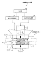
図1は、実施例1に係る摩擦撹拌接合装置を模式的に表した概略構成図である。図2から図4は、第1ショルダ部の形状の一例を示す平面図である。 FIG. 1 is a schematic configuration diagram schematically illustrating the friction stir welding apparatus according to the first embodiment. 2 to 4 are plan views showing an example of the shape of the first shoulder portion.
実施例1の摩擦撹拌接合装置1は、重ね合わせた一対の金属板5の表裏に配置される一対の回転ツール21,22を用いて摩擦撹拌することにより、重ね合わせた一対の金属板5を接合する、いわゆる摩擦撹拌接合(FSW:Friction Stir Welding)を行う装置である。先ず、図1及び図4を参照し、接合対象となる一対の金属板5について説明する。
The friction stir welding apparatus 1 according to the first embodiment is configured to frictionally stir using a pair of
金属板5は、例えば、アルミニウム合金を用いて構成されている。図1に示すように、一対の金属板5は、積層方向に重ね合わせられることで、一対の金属板5の重ね合わせ面となる界面6が形成される。また、一対の金属板5は、一方の金属板5の厚さと、他方の金属板5の厚さとが略同じ厚さとなっている。なお、摩擦撹拌接合により接合された一対の金属板5は、接合材として取り扱われる。
The
次に、図1を参照して、摩擦撹拌接合装置1について説明する。図1に示す摩擦撹拌接合装置1は、一対の金属板5の積層方向の両側から摩擦撹拌接合を行っている。摩擦撹拌接合装置1は、摩擦撹拌工具10と、第1押圧回転機構11と、第2押圧回転機構12と、制御部20とを備えている。なお、摩擦撹拌接合装置1は、一対の金属板5の位置を固定した状態で、摩擦撹拌工具10を移動させながら、摩擦撹拌接合を行ってもよいし、摩擦撹拌工具10の位置を固定した状態で、一対の金属板5を移動させながら、摩擦撹拌接合を行ってもよい。
Next, the friction stir welding apparatus 1 will be described with reference to FIG. A friction stir welding apparatus 1 shown in FIG. 1 performs friction stir welding from both sides in the stacking direction of a pair of
摩擦撹拌工具10は、いわゆるボビンツールと呼ばれる工具であり、第1回転ツール21と第2回転ツール22とを有している。第1回転ツール21は、一対の金属板5を挟んで、積層方向の一方側(表面側:図1の上側)に配置されている。第1回転ツール21は、第1回転軸I1を中心に回転すると共に、一方側の金属板5の表面に押圧される。第2回転ツール22は、一対の金属板5を挟んで、積層方向の他方側(裏面側:図1の下側)に配置されている。第2回転ツール22は、第2回転軸I2を中心に回転すると共に、他方側の金属板5の裏面に押圧される。そして、第1回転ツール21と第2回転ツール22とは、積層方向において対向するように配置され、第1回転ツール21及び第2回転ツール22の回転方向は、相互に逆方向となっている。また、第1回転ツール21の第1回転軸I1と第2回転ツール22の第2回転軸I2とは、同軸となっている。このため、第1回転軸I1及び第2回転軸I2は、一方の金属板5の表面及び他方の金属板5の裏面に対して、それぞれ直交している。
The friction stir tool 10 is a so-called bobbin tool, and includes a first
なお、実施例1では、第1回転ツール21及び第2回転ツール22の回転方向が、相互に逆方向となるようにしたが、この構成に限定されない。第1回転ツール21及び第2回転ツール22は、摩擦撹拌接合に適していれば、相互に同じ回転方向であってもよく、また、いずれの回転速度であってもよい。
In the first embodiment, the rotation directions of the
第1回転ツール21は、第1ツール本体31を有している。第1ツール本体31は、一方の金属板5の表面に接触可能に設けられている。この第1ツール本体31は、第2回転ツール22の後述するシャフト43が挿通されるシャフト挿通穴33が形成されている。シャフト挿通穴33は、第1回転軸I1と同軸上に形成され、中空円柱状に形成されている。また、第1ツール本体31は、第2回転ツール22側となる先端側に、第1ショルダ部35が形成されている。第1ショルダ部35は、その先端側の面が、一方側の金属板5の表面と接する円環状の第1ショルダ面35aとなっている。第1回転ツール21は、第1ショルダ部35の第1ショルダ面35aを一方の金属板5の表面に接触させた状態で回転することで、一方の金属板5に対して摩擦による熱を与える。
The
ここで、第1ショルダ部35は、図2から図4に示す形状となっており、実施例1では、いずれの形状であってもよい。第1ショルダ部35は、第1ショルダ面35aから第1ツール本体31側に溝形状の凹部36が形成されている。この凹部36は、第1ショルダ部35と一方の金属板5とを擦ることで軟化した金属材が、第1ショルダ部35の中心側へ向かうような形状となっている。
Here, the
具体的に、図2に示す凹部36は、1本で構成されており、1本の凹部36は、第1ショルダ面35aにおいて、外側から内側に向かう渦巻状(スクロール形状)に配置されている。図3に示す凹部36は、2本で構成されており、2本の凹部36は、第1ショルダ面35aにおいて、180°位相が異なる位置に設けられ、外側から内側に向かう渦巻状に配置されている。図4に示す凹部36は、複数本で構成されており、複数本の凹部36は、第1ショルダ面35aの周方向に所定の間隔を空けて設けられると共に、外側から内側に向かって直線状に配置されている。
Specifically, the
再び、図1を参照し、第2回転ツール22は、第2ツール本体41と、プローブ42と、シャフト43と、を有している。第2ツール本体41は、他方の金属板5の裏面に接触可能に設けられている。第2ツール本体41は、第1回転ツール21側となる先端側に、第2ショルダ部45が形成されている。第2ショルダ部45は、第1ショルダ部35と同様に構成されており、その先端側の面が、他方側の金属板5の裏面と接する円環状の第2ショルダ面45aとなっている。第2回転ツール22は、第2ショルダ部45の第2ショルダ面45aを他方の金属板5の裏面に接触させた状態で回転することで、他方の金属板5に対して摩擦による熱を与える。
Referring again to FIG. 1, the
なお、第2ショルダ部45は、第1ショルダ部35と同様の凹部36が設けられており、凹部36については、第1ショルダ部35と同様であるため、説明を省略する。
The
このため、一対の金属板5は、第1ショルダ部35と第2ショルダ部45との間に挟み込まれ、この状態で、第1回転ツール21及び第2回転ツール22が回転することで、一対の金属板5の表裏両側から入熱が与えられる。
For this reason, the pair of
プローブ42は、第2ツール本体41の第2ショルダ面45aの中心から第1回転ツール21側に突出して設けられている。プローブ42は、第2回転軸I2と同軸上に設けられ、円柱状に形成されている。このプローブ42は、第1ツール本体31の第1ショルダ部35と第2ツール本体41の第2ショルダ部45との間に設けられることから、第1ショルダ部35と第2ショルダ部45との間に挟み込まれた一対の金属板5の内部に位置することとなる。このプローブ42は、第2ツール本体41と一体となって回転するように、第2ツール本体41に固定されている。また、プローブ42の外周面には、軟化した金属材を撹拌するための撹拌溝44が形成されている。
The
シャフト43は、プローブ42の第1ショルダ部35側から第1回転ツール21側に延びて設けられている。シャフト43は、第1回転ツール21のシャフト挿通穴33に挿通される。このシャフト43は、第2回転軸I2と同軸上に設けられ、円柱状に形成されている。
The
ここで、図1を参照して、プローブ42の外周面に形成される撹拌溝44について説明する。撹拌溝44は、積層方向の一方側(表側)に形成される第1ねじ溝51と、積層方向の他方側(裏側)に形成される第2ねじ溝52とを有している。
Here, with reference to FIG. 1, the stirring
第1ねじ溝51は、撹拌した金属材を第1ショルダ部35側から界面6に向かって流動させる溝となっている。第1ねじ溝51は、一本のねじ溝で構成されていてもよいし、複数本のねじ溝で構成されていてもよい。第1ねじ溝51によって形成される第1ねじ山54は、その突出方向(径方向外側)の高さが、第2回転軸I2に沿って同じ高さとなっている。
The
第2ねじ溝52は、撹拌した金属材を第2ショルダ部45側から界面6に向かって流動させる溝となっており、第1ねじ溝51の回転方向と逆方向となっている。第2ねじ溝52は、第1ねじ溝51と同様に、一本のねじ溝で構成されていてもよいし、複数本のねじ溝で構成されていてもよい。第2ねじ溝52によって形成される第2ねじ山55は、その突出方向(径方向外側)の高さが、第2回転軸I2に沿って同じ高さとなっている。
The
ここで、第2回転軸I2の軸方向において、第1ねじ溝51と第2ねじ溝52との境界53は、一対の金属板5の界面6とほぼ同じ位置となるように、プローブ42が形成されている。このため、回転するプローブ42は、第1ねじ溝51により撹拌された金属材を、一方の金属板5側から界面6を跨いで他方の金属板5側に流動させる。また、回転するプローブ42は、第2ねじ溝52により撹拌された金属材を、他方の金属板5側から界面6を跨いで一方の金属板5側に流動させる。
Here, in the axial direction of the second rotation axis I2, the
また、第1ねじ溝51と第2ねじ溝52とは、第2回転ツール22の第2回転軸I2の周方向おいて、同じ位相となるように形成されている。なお、実施例1では、第1ねじ溝51と第2ねじ溝52とを、第2回転軸I2の周方向おいて同じ位相としたが、この構成に限定されない。例えば、第1ねじ溝51及び第2ねじ溝52が1本のねじ溝で構成される場合には、180°位相が異なる位置に形成してもよい。また、例えば、第1ねじ溝51及び第2ねじ溝52が2本のねじ溝で構成される場合には、90°位相が異なる位置に形成してもよい。このとき、第1ねじ溝51と第2ねじ溝52とは、二つのねじ溝の対称性を維持した状態で異なる位相となるように形成されることが好ましい。
Further, the
次に、図1を参照して、第1押圧回転機構11及び第2押圧回転機構12について説明する。第1押圧回転機構11は、第1回転ツール21の第1ツール本体31に連結されており、制御部20によって制御されている。第1押圧回転機構11は、第1回転ツール21の第1ツール本体31を一方の金属板5へ向けて移動させると共に、第1回転ツール21を回転させる。このため、第1押圧回転機構11は、第1回転ツール21の第1ショルダ部35の第1ショルダ面35aを、一方の金属板5の表面に押し当てた状態で、第1回転ツール21を回転させる。
Next, with reference to FIG. 1, the 1st
第2押圧回転機構12は、第2回転ツール22のシャフト43に連結されており、制御部20によって制御されている。第2押圧回転機構12は、第2回転ツール22の第2ツール本体41を他方の金属板5へ向けて移動させると共に、第2回転ツール22を回転させる。このため、第2押圧回転機構12は、第2回転ツール22の第2ショルダ部45の第2ショルダ面45aを、他方の金属板5の裏面に押し当てた状態で、第2回転ツール22を回転させる。
The second pressing and
制御部20は、第1押圧回転機構11及び第2押圧回転機構12が接続され、これらをそれぞれ制御する。具体的に、制御部20は、第1押圧回転機構11及び第2押圧回転機構12を制御して、第1回転ツール21と第2回転ツール22との間に挟まれる一対の金属板5に対する荷重が所定の荷重となるように、第1回転ツール21及び第2回転ツール22を一対の金属板5へ向けて移動させる。また、制御部20は、第1押圧回転機構11及び第2押圧回転機構12を制御して、第1回転ツール21及び第2回転ツール22の回転方向が相互に逆方向となるように、また、所定の回転速度となるように、第1回転ツール21及び第2回転ツール22を回転制御する。
The
次に、図1を参照して、上記の摩擦撹拌接合装置1を用いた摩擦撹拌接合方法について説明する。摩擦撹拌接合を行う場合、制御部20は、第1押圧回転機構11及び第2押圧回転機構12を制御して、一対の金属板5を、第1回転ツール21及び第2回転ツール22により挟み込み、第1回転ツール21及び第2回転ツール22を回転させる。この後、制御部20は、第1回転ツール21及び第2回転ツール22から一対の金属板5に対して与えられる荷重が所定の荷重となるように、第1押圧回転機構11及び第2押圧回転機構12を制御する。そして、制御部20は、接合開始点から接合終了点まで、一対の金属材5または第1回転ツール21及び第2回転ツール22を移動させて、摩擦撹拌接合を行う。これにより、上記の摩擦撹拌接合装置1を用いて摩擦撹拌接合が行われた一対の金属材5は、界面6において接合された接合材とすることができる。
Next, a friction stir welding method using the friction stir welding apparatus 1 will be described with reference to FIG. When performing friction stir welding, the
以上のように、実施例1の構成によれば、第1回転ツール21及び第2回転ツール22を回転させることで、第1ショルダ部35及び第2ショルダ部45によって一対の金属板5の表裏両側に入熱を行いながら、入熱(摩擦熱)により軟化した金属材をプローブ42により撹拌することができる。このとき、回転するプローブ42の第1ねじ溝51により撹拌した金属材を、第1ショルダ部35側から界面6に向かって流動させることができ、また、回転するプローブ42の第2ねじ溝52により撹拌した金属材を、第2ショルダ部45側から界面6に向かって流動させることができる。これにより、第1ねじ溝51及び第2ねじ溝52によって流動する金属材は、界面6を跨いで流動するため、界面6における接合強度を強固にすることができ、界面破断等の接合不良を抑制することができる。
As described above, according to the configuration of the first embodiment, by rotating the first
また、実施例1の構成によれば、プローブ42の一方側に第1ねじ溝51を形成し、プローブ42の他方側に第2ねじ溝52を形成することで、簡易に撹拌溝44を構成することができる。なお、第1ねじ溝51及び第2ねじ溝52を、複数本とすることで、撹拌による金属材の流動を促進することができる。
Further, according to the configuration of the first embodiment, the
なお、上記したように、第1ねじ溝51と第2ねじ溝52とが1本のねじ溝で構成される場合、180°位相を異ならせることで、180°位相が異なる位置において、金属材の流動を発生させることができるため、界面6における金属材の撹拌性を向上させることができる。なお、第1ねじ溝51と第2ねじ溝52とが2本のねじ溝で構成される場合、90°位相を異ならせれば、上記と同様に、界面6における金属材の撹拌性を向上させることができる。このとき、第1ねじ溝51と第2ねじ溝52とを、プローブ42の第2回転軸I2に対し対称性を維持した状態で異なる位相となるように形成することで、プローブ42の回転バランスをとることができる。
As described above, in the case where the
また、実施例1の構成によれば、第1回転ツール21の回転方向を、第2回転ツール22の回転方向と逆方向にすることができる。このため、第1ショルダ部35の回転によって形成される金属材の流動と、第2ショルダ部45の回転によって形成される金属材の流動とによって、界面6において流動する金属材に対しせん断力を発生させることができる。このため、界面6における金属材の撹拌性を向上させることができる。さらには、接合を阻害する酸化被膜等の界面6の被膜を破壊することができる。
In addition, according to the configuration of the first embodiment, the rotation direction of the
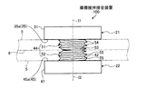
次に、図5Aを参照して、実施例2に係る摩擦撹拌接合装置100について説明する。図5Aは、実施例2に係る摩擦撹拌接合装置の摩擦撹拌工具を模式的に表した概略構成図である。なお、実施例2では、重複した記載を避けるべく、実施例1と異なる部分について説明すると共に、実施例1と同様の構成である部分については、同じ符号を付す。実施例2に係る摩擦撹拌接合装置100は、摩擦撹拌工具10のプローブ42に形成される第1ねじ溝51及び第2ねじ溝52の形状が、実施例1の形状と異なっている。以下、実施例2に係る摩擦撹拌接合装置100について説明する。
Next, the friction
図5Aに示すように、実施例2に係る摩擦撹拌接合装置100において、摩擦撹拌工具10の第2回転ツール22のプローブ42は、第1ねじ溝51の第1ねじ山54及び第2ねじ溝52の第2ねじ山55が、境界53に向かって高くなっている。つまり、第1ねじ山54の突出方向(径方向の外側に突出する方向)における高さは、第2回転軸I2の軸方向に沿って、第1ショルダ部35から境界53に向かうにつれて高くなるテーパ形状となっている。また、第2ねじ山55の突出方向における高さは、第2ショルダ部45から境界53に向かうにつれて高くなるテーパ形状となっている。
As shown in FIG. 5A, in the friction
具体的に、テーパ形状となる第1ねじ山54は、実施例1に示す形状、すなわち、第2回転軸I2の軸方向に沿って同じ高さとなる第1ねじ山54に対し、テーパ加工を行って第1ねじ山54の頂部を切り欠くことで、実施例2に示す形状とする。第2ねじ山55も、第1ねじ山54と同様に加工する。
Specifically, the
以上のように、実施例2の構成によれば、第1ショルダ部35側の第1ねじ山54を低くし、境界53側の第1ねじ山54を高くすることができる。このため、回転するプローブ42に形成される第1ねじ溝51は、第1ショルダ部35側から界面6へ向かう金属材の流動量を減少させることができる。また、第2ショルダ部45側の第2ねじ山55を低くし、境界53側の第2ねじ山55を高くすることができる。このため、回転するプローブ42に形成される第2ねじ溝52は、第2ショルダ部45側から界面6へ向かう金属材の流動量を減少させることができる。このため、界面6への金属材の過剰な流動によって発生する撹拌域の幅方向の過度な広がりを抑制することができることから、金属材が接合不良部を形成することなく、界面6において金属材を好適に撹拌することができる。
As described above, according to the configuration of the second embodiment, the
なお、実施例2では、第2回転軸I2の軸方向に沿って同じ高さとなる第1ねじ山54に対し、第1ねじ山54の頂部を切り欠くテーパ加工を行うことで、テーパ形状となる第1ねじ山54を形成した。しかしながら、このテーパ加工に限定されず、第1ねじ山54及び第2ねじ山55は、第1ねじ溝51及び第2ねじ溝52の加工時において、境界53に向かって第1ねじ山54及び第2ねじ山55が高くなるように形成してもよく、例えば、図5Bに示す変形例1、または図5Cに示す変形例2の構成としてもよい。変形例1では、第2回転ツール22の加工前のプローブ42の直径が、境界53に向かって大きくなるテーパ形状となっており、この加工前のテーパ形状のプローブ42に対し、同じ高さのねじ山53,54となるように第1ねじ溝51及び第2ねじ溝52を形成することで、第1ねじ山54及び第2ねじ山55が境界53に向かって高くなるように形成している。また、変形例2では、第2回転ツール22の加工前のプローブ42の直径が、軸方向において同じ径となる円柱形状っており、この加工前の円柱形状のプローブ42に対し、境界53に向かって溝が深くなるように第1ねじ溝51及び第2ねじ溝52を形成することで、第1ねじ山54及び第2ねじ山55が境界53に向かって高くなるように形成している。
In the second embodiment, the
次に、図6Aから図6Cを参照して、実施例3に係る摩擦撹拌接合装置110について説明する。図6Aは、実施例3に係る摩擦撹拌接合装置の摩擦撹拌工具を模式的に表した概略構成図である。図6Bは、摩擦撹拌工具のプローブを軸方向に直交する面で切った一例の断面図である。図6Cは、摩擦撹拌工具のプローブを軸方向に直交する面で切った一例の断面図である。なお、実施例3でも、重複した記載を避けるべく、実施例1及び2と異なる部分について説明すると共に、実施例1及び2と同様の構成である部分については、同じ符号を付す。実施例3に係る摩擦撹拌接合装置110は、実施例1の第1ねじ溝51及び第2ねじ溝52に対し、平坦面が形成される構成となっている。以下、実施例3に係る摩擦撹拌接合装置110について説明する。
Next, the friction stir welding apparatus 110 according to the third embodiment will be described with reference to FIGS. 6A to 6C. FIG. 6A is a schematic configuration diagram schematically illustrating a friction stir tool of the friction stir welding apparatus according to the third embodiment. FIG. 6B is a cross-sectional view of an example in which the probe of the friction stir tool is cut along a plane orthogonal to the axial direction. FIG. 6C is a cross-sectional view of an example in which the probe of the friction stir tool is cut along a plane orthogonal to the axial direction. In the third embodiment as well, parts that are different from the first and second embodiments will be described in order to avoid redundant descriptions, and the same reference numerals will be given to parts that have the same configuration as the first and second embodiments. The friction stir welding apparatus 110 according to the third embodiment is configured such that a flat surface is formed with respect to the
図6Aに示すように、実施例3に係る摩擦撹拌接合装置110において、摩擦撹拌工具10の第2回転ツール22のプローブ42に形成される第1ねじ溝51及び第2ねじ溝52には、平坦面111が形成されている。この平坦面111は、第2回転軸I2の軸方向に沿って接線方向に切った面となっている。平坦面111は、プローブ42の周方向に1つ形成してもよいし、所定の間隔を空けて複数形成してもよい。
As shown in FIG. 6A, in the friction stir welding apparatus 110 according to the third embodiment, the
なお、平坦面111は、実施例1に示す形状、すなわち、第2回転軸I2の軸方向に沿って同じ高さとなる第1ねじ山54及び第2ねじ山55に対し、フラット加工を行って第1ねじ山54及び第2ねじ山55の頂部を切り欠くことで、実施例3に示す形状とする。
The
ここで、平坦面111は、図6Bに示すように、周方向に2つ形成してもよい。2つの平坦面111は、プローブ42の第2回転軸I2に対して対称性を有するように配置されている。つまり、2つの平坦面111は、プローブ42の第2回転軸I2を中心にして、180°位相を異ならせた位置となっている。また、平坦面111は、図6Cに示すように、周方向に4つ形成してもよい。4つの平坦面111は、プローブ42の第2回転軸I2に対して対称性を有するように配置されている。つまり、4つの平坦面111は、プローブ42の第2回転軸I2を中心にして、90°位相を異ならせた位置となっている。
Here, as shown in FIG. 6B, two
以上のように、実施例3の構成によれば、第1ねじ溝51及び第2ねじ溝52に平坦面111を形成することで、界面6において金属材の過剰な流動によって発生する撹拌域の幅方向の過度な広がりを抑制することができることから、金属材が接合不良部を形成することなく、界面6において金属材を好適に撹拌することができる。
As described above, according to the configuration of the third embodiment, by forming the
また、実施例3では、複数の平坦面111を、プローブ42の第2回転軸I2に対して対称性を有するように配置することができるため、プローブ42の回転バランスをとることができる。
In the third embodiment, the plurality of
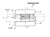
次に、図7を参照して、実施例4に係る摩擦撹拌接合装置120について説明する。図7は、実施例4に係る摩擦撹拌接合装置の摩擦撹拌工具を模式的に表した概略構成図である。なお、実施例4でも、重複した記載を避けるべく、実施例1から3と異なる部分について説明すると共に、実施例1から3と同様の構成である部分については、同じ符号を付す。実施例4に係る摩擦撹拌接合装置120は、実施例1の第1ねじ溝51及び第2ねじ溝52を境界53周りにのみ設けた構成となっている。以下、実施例4に係る摩擦撹拌接合装置120について説明する。
Next, the friction stir welding apparatus 120 according to the fourth embodiment will be described with reference to FIG. FIG. 7 is a schematic configuration diagram schematically illustrating a friction stir tool of the friction stir welding apparatus according to the fourth embodiment. In the fourth embodiment, portions that are different from the first to third embodiments will be described in order to avoid redundant descriptions, and the same reference numerals are given to the portions that have the same configuration as the first to third embodiments. The friction stir welding apparatus 120 according to the fourth embodiment has a configuration in which the
図7に示すように、実施例4に係る摩擦撹拌接合装置120において、摩擦撹拌工具10の第2回転ツール22のプローブ42に形成される第1ねじ溝51は、第2回転軸I2の軸方向において、第1ショルダ部35と境界53との間の所定の部位から、境界53まで設けられている。このため、プローブ42は、第1ショルダ部35から第1ショルダ部35と境界53との間の所定の部位までの間が、第1ねじ溝51が形成されない滑らかな外周面121となる。また、第2ねじ溝52は、第2回転軸I2の軸方向において、第2ショルダ部45と境界53との間の所定の部位から、境界53まで設けられている。このため、プローブ42は、第2ショルダ部45から第2ショルダ部45と境界53との間の所定の部位までの間が、第2ねじ溝52が形成されない滑らかな外周面122となる。
As shown in FIG. 7, in the friction stir welding apparatus 120 according to the fourth embodiment, the
以上から、プローブ42には、第1ショルダ部35から所定の部位までの間の外周面121と、所定の部位から境界53までの間の第1ねじ溝51と、第2ショルダ部45から所定の部位までの間の外周面122と、所定の部位から境界53までの間の第2ねじ溝52と、が形成される。
From the above, the
以上のように、実施例4の構成によれば、第1ショルダ部35から所定の部位までの間に、第1ねじ溝51が形成されないため、第1ショルダ部35側から界面6へ向かう金属材の流動量を減少させることができる。また、第2ショルダ部45から所定の部位までの間に、第2ねじ溝52が形成されないため、第2ショルダ部45側から界面6へ向かう金属材の流動量を減少させることができる。このため、界面6への金属材の過剰な流動によって発生する撹拌域の幅方向の過度な広がりを抑制することができることから、金属材が接合不良部を形成することなく、界面6において金属材を好適に撹拌することができる。
As described above, according to the configuration of the fourth embodiment, since the
次に、図8を参照して、実施例5に係る摩擦撹拌接合装置130について説明する。図8は、実施例5に係る摩擦撹拌接合装置の摩擦撹拌工具を模式的に表した概略構成図である。なお、実施例5でも、重複した記載を避けるべく、実施例1から4と異なる部分について説明すると共に、実施例1から4と同様の構成である部分については、同じ符号を付す。実施例5に係る摩擦撹拌接合装置130は、実施例1の第1ねじ溝51の一部及び第2ねじ溝52の一部が境界53を超えて形成される構成となっている。以下、実施例5に係る摩擦撹拌接合装置130について説明する。
Next, the friction
図8に示すように、実施例5に係る摩擦撹拌接合装置130において、摩擦撹拌工具10の第2回転ツール22のプローブ42に形成される第1ねじ溝51及び第2ねじ溝52は、境界53におけるプローブ42の周方向において、重複(オーバーラップ)した状態となっている。具体的に、第2回転軸I2の軸方向において、第1ねじ溝51の一部は、境界53を超えて第2ねじ溝52側に形成される一方で、第1ねじ溝51の他の一部は、境界53を超えて形成される第2ねじ溝52を許容すべく、境界53よりも第1ショルダ部35側に形成されている。また、第2回転軸I2の軸方向において、第2ねじ溝52の一部は、境界53を超えて第1ねじ溝51側に形成される一方で、第2ねじ溝52の他の一部は、境界53を超えて形成される第1ねじ溝51を許容すべく、境界53よりも第2ショルダ部45側に形成されている。
As shown in FIG. 8, in the friction
実施例5の構成によれば、第1ねじ溝51及び第2ねじ溝52を、境界53におけるプローブ42の周方向において、重複(オーバーラップ)させることができるため、第1ねじ溝51及び第2ねじ溝52によって、界面6を跨いで金属材を流動させ易くでき、界面6における金属材の撹拌性を向上させることができる。
According to the configuration of the fifth embodiment, the
ここで、図9から図11を参照して、上記した実施例1から3における界面6の強度と、下記する比較例1及び比較例2における界面の強度との比較について説明する。図9は、比較例1に係る摩擦撹拌接合装置の摩擦撹拌工具を模式的に表した概略構成図である。図10は、比較例2に係る摩擦撹拌接合装置の摩擦撹拌工具を模式的に表した概略構成図である。図11は、接合材の界面における強度を比較した表である。なお、比較例1及び比較例2でも、重複した記載を避けるべく、実施例1から5と異なる部分について説明すると共に、実施例1から5と同様の構成である部分については、同じ符号を付す。
Here, with reference to FIG. 9 to FIG. 11, a comparison between the strength of the
図9に示すように、比較例1の摩擦撹拌接合装置140の摩擦撹拌工具10において、第2回転ツール22のプローブ42の外周面には、周方向に沿って形成される円環状のリング溝が、第2回転軸I2の軸方向に所定ピッチで複数形成されている。
As shown in FIG. 9, in the friction stir tool 10 of the friction
また、図10に示すように、比較例2の摩擦撹拌接合装置150の摩擦撹拌工具10において、第2回転ツール22のプローブ42の外周面には、実施例1の第1ねじ溝51及び第2ねじ溝52を、境界53周り以外に設けた構成となっている。つまり、比較例2は、実施例4と逆の構成となっており、プローブ42には、第1ショルダ部35から所定の部位までの間の第1ねじ溝51と、第2ショルダ部45から所定の部位までの間の第2ねじ溝52と、第1ショルダ部35側の所定の部位から境界53を挟んで第2ショルダ部45側の所定の部位までの滑らかな外周面151と、が形成される。
Further, as shown in FIG. 10, in the friction stir tool 10 of the friction
ここで、図11の表に示すように、摩擦撹拌接合された接合材である一対の金属板5の界面6の強度は、一方の金属板5と他方の金属板5とを引っ張ったときの引張強度で評価されている。実施例1の引張強度を、Ns1とし、実施例2の引張強度を、Ns2とし、実施例3の引張強度を、Ns3とする。また、比較例1の引張強度を、Nw1とし、比較例2の引張強度を、Nw2とする。
Here, as shown in the table of FIG. 11, the strength of the
このとき、比較例1の引張強度Nw1が最も弱く、比較例2の引張強度Nw2が比較例1の引張強度Nw1よりも大きくなることが確認された。しかしながら、比較例1及び比較例2において、一方の金属板5と他方の金属板5とを引っ張ったときの破断は、界面6で発生することが確認された。
At this time, it was confirmed that the tensile strength Nw1 of Comparative Example 1 was the weakest, and the tensile strength Nw2 of Comparative Example 2 was greater than the tensile strength Nw1 of Comparative Example 1. However, in Comparative Example 1 and Comparative Example 2, it was confirmed that the fracture occurred when the one
一方で、実施例1の引張強度Ns1は、比較例2の引張強度Nw2よりも大きくなることが確認された。また、実施例2の引張強度Ns2は最も強く、実施例3の引張強度Ns3よりも大きくなることが確認された。実施例3の引張強度Ns3は、実施例1の引張強度Ns1よりも大きくなることが確認された。そして、実施例1から実施例3において、一方の金属板5と他方の金属板5とを引っ張ったときの破断は、界面6以外で発生することが確認された。
On the other hand, it was confirmed that the tensile strength Ns1 of Example 1 was larger than the tensile strength Nw2 of Comparative Example 2. Further, it was confirmed that the tensile strength Ns2 of Example 2 was the strongest and was larger than the tensile strength Ns3 of Example 3. It was confirmed that the tensile strength Ns3 of Example 3 was larger than the tensile strength Ns1 of Example 1. In Examples 1 to 3, it was confirmed that the breakage occurred when one
以上から、引張強度は、強いほうから順に、引張強度Ns2、引張強度Ns3、引張強度Ns1、引張強度Nw2、引張強度Nw1となっている。 From the above, the tensile strength is, in order from the strongest, the tensile strength Ns2, the tensile strength Ns3, the tensile strength Ns1, the tensile strength Nw2, and the tensile strength Nw1.
次に、図12を参照して、実施例6に係る摩擦撹拌接合装置200について説明する。図12は、実施例6に係る摩擦撹拌接合装置の摩擦撹拌工具を模式的に表した概略構成図である。なお、実施例6でも、重複した記載を避けるべく、実施例1から5と異なる部分について説明すると共に、実施例1から5と同様の構成である部分については、同じ符号を付す。実施例6に係る摩擦撹拌接合装置200は、一対の金属板5の厚さが異なる厚さとなっている。以下、実施例6に係る摩擦撹拌接合装置200について説明する。
Next, the friction
図12に示すように、一対の金属板5は、一方(図12の上方)の金属板5が積層方向において薄く、他方(図12の下方)の金属板5が積層方向において厚くなっている。このとき、実施例6に係る摩擦撹拌接合装置200において、摩擦撹拌工具10の第2回転ツール22のプローブ42に形成される第1ねじ溝51及び第2ねじ溝52は、その境界53が、一対の金属板5の界面6とほぼ同じ位置となるように、プローブ42が形成されている。このため、第2回転軸I2の軸方向において、第1ねじ溝51の長さは短く、第2ねじ溝52の長さは長くなっている。
As shown in FIG. 12, in the pair of
実施例6の構成によれば、回転するプローブ42の第1ねじ溝51により撹拌した金属材を、第1ショルダ部35側から界面6に向かって流動させることができ、また、回転するプローブ42の第2ねじ溝52により撹拌した金属材を、第2ショルダ部45側から界面6に向かって流動させることができる。これにより、一対の金属板5の厚さが異なる場合であっても、第1ねじ溝51及び第2ねじ溝52によって流動する金属材は、界面6を跨いで流動するため、界面6における接合強度を強固にすることができ、界面破断等の接合不良を抑制することができる。
According to the configuration of the sixth embodiment, the metal material stirred by the
次に、図13を参照して、実施例7に係る摩擦撹拌接合装置210について説明する。図13は、実施例7に係る摩擦撹拌接合装置の摩擦撹拌工具を模式的に表した概略構成図である。なお、実施例7でも、重複した記載を避けるべく、実施例1から6と異なる部分について説明すると共に、実施例1から6と同様の構成である部分については、同じ符号を付す。実施例7に係る摩擦撹拌接合装置210は、一対の金属板5の厚さが異なる厚さとなっており、摩擦撹拌工具10のプローブ42に形成される第1ねじ溝51及び第2ねじ溝52の形状が、実施例6の形状と異なっている。以下、実施例7に係る摩擦撹拌接合装置210について説明する。なお、実施例6と同様に、一対の金属板5は、一方(図13の上方)の金属板5が積層方向において薄く、他方(図13の下方)の金属板5が積層方向において厚くなっている。
Next, the friction stir welding apparatus 210 according to the seventh embodiment will be described with reference to FIG. FIG. 13 is a schematic configuration diagram schematically illustrating a friction stir tool of the friction stir welding apparatus according to the seventh embodiment. In Example 7, parts different from those in Examples 1 to 6 will be described in order to avoid redundant description, and parts having the same configurations as those in Examples 1 to 6 are denoted by the same reference numerals. In the friction stir welding apparatus 210 according to the seventh embodiment, the pair of
図13に示すように、実施例7に係る摩擦撹拌接合装置210において、摩擦撹拌工具10の第2回転ツール22のプローブ42に形成される第1ねじ溝51は、第2回転軸I2の軸方向において、第1ショルダ部35から境界53まで設けられている。また、第2ねじ溝52は、第2回転軸I2の軸方向において、第2ショルダ部45と境界53との間の所定の部位から、境界53まで設けられている。このとき、第1ねじ溝51と第2ねじ溝52との第2回転軸I2の軸方向における長さは同じ長さとなっている。このため、プローブ42は、第2ショルダ部45から第2ショルダ部45と境界53との間の所定の部位までの間が、第2ねじ溝52が形成されない滑らかな外周面211となる。
As shown in FIG. 13, in the friction stir welding apparatus 210 according to the seventh embodiment, the
以上から、プローブ42には、第1ショルダ部35から境界53までの間の第1ねじ溝51と、第2ショルダ部45から所定の部位までの間の外周面211と、所定の部位から境界53までの間の第2ねじ溝52と、が形成される。
From the above, the
以上のように、実施例7の構成によれば、第2ショルダ部45から所定の部位までの間に、第2ねじ溝52が形成されないため、第2ショルダ部45側から界面53へ向かう金属材の流動量を減少させることができる。このため、界面6への金属材の過剰な流動によって発生する撹拌域の幅方向の過度な広がりを抑制することができることから、金属材が接合不良部を形成することなく、界面6において金属材を好適に撹拌することができる。
As described above, according to the configuration of the seventh embodiment, since the
次に、図14を参照して、実施例8に係る摩擦撹拌接合装置220について説明する。図14は、実施例8に係る摩擦撹拌接合装置の摩擦撹拌工具を模式的に表した概略構成図である。なお、実施例8でも、重複した記載を避けるべく、実施例1から7と異なる部分について説明すると共に、実施例1から7と同様の構成である部分については、同じ符号を付す。実施例8に係る摩擦撹拌接合装置220は、一対の金属板5の厚さが異なる厚さとなっており、第1回転ツール21の回転速度と第2回転ツール22の回転速度とが異なっている。以下、実施例8に係る摩擦撹拌接合装置220について説明する。なお、実施例6及び7と同様に、一対の金属板5は、一方(図14の上方)の金属板5が積層方向において薄く、他方(図14の下方)の金属板5が積層方向において厚くなっている。
Next, the friction stir welding apparatus 220 according to the eighth embodiment will be described with reference to FIG. FIG. 14 is a schematic configuration diagram schematically illustrating a friction stir tool of the friction stir welding apparatus according to the eighth embodiment. In Example 8, parts that are different from Examples 1 to 7 will be described in order to avoid duplicated descriptions, and parts having the same configurations as those of Examples 1 to 7 are denoted by the same reference numerals. In the friction stir welding apparatus 220 according to the eighth embodiment, the thickness of the pair of
図14に示すように、実施例8に係る摩擦撹拌接合装置220において、摩擦撹拌工具10の第2回転ツール22のプローブ42に形成される第1ねじ溝51及び第2ねじ溝52は、実施例6と同様の構成となっている。このため、摩擦撹拌工具10の説明については省略する。
As shown in FIG. 14, in the friction stir welding apparatus 220 according to the eighth embodiment, the
制御部20は、厚さが厚い金属板5に接する回転ツールの回転速度を速くし、厚さが薄い金属板5に接する回転ツールの回転速度を遅くする。つまり、図14では、制御部20は、第1回転ツール21の回転速度を遅くし、第2回転ツール22の回転速度を速くする。
The
以上のように、実施例8の構成によれば、制御部20は、厚さが厚い金属板5に接するショルダ部35,45の回転速度を速くすることができるため、厚さが厚い金属板5に対する入熱量を多くすることができる一方で、厚さが薄い金属板5に対する入熱量を少なくすることができる。このため、二つの金属板5の界面6付近の温度分布をそろえることができるため、界面6近傍における二つのショルダ部35,45から中央に集まる金属材の流動性を同じ状態にすることが可能であり、一対の金属板5の厚さが異なる場合であっても、界面6を跨いで金属材を、バランスを取りながら流動させることができる。なお、実施例8の構成は、実施例7の摩擦撹拌工具10に適用してもよい。
As described above, according to the configuration of the eighth embodiment, the
なお、実施例8のプローブ42の撹拌溝44は、実施例6及び実施例7に限定されず、界面6を跨いで金属材を流動させる撹拌溝44であれば、いずれであってもよい。
In addition, the stirring
次に、図15を参照して、実施例9に係る摩擦撹拌接合装置230について説明する。図15は、実施例9に係る摩擦撹拌接合装置の摩擦撹拌工具を模式的に表した概略構成図である。なお、実施例9でも、重複した記載を避けるべく、実施例1から8と異なる部分について説明すると共に、実施例1から8と同様の構成である部分については、同じ符号を付す。実施例9に係る摩擦撹拌接合装置230は、一対の金属板5の厚さが異なる厚さとなっており、第1ショルダ部35の直径と第2ショルダ部45の直径とが異なっている。以下、実施例9に係る摩擦撹拌接合装置230について説明する。なお、実施例6から8と同様に、一対の金属板5は、一方(図15の上方)の金属板5が積層方向において薄く、他方(図15の下方)の金属板5が積層方向において厚くなっている。
Next, the friction stir welding apparatus 230 according to the ninth embodiment will be described with reference to FIG. FIG. 15 is a schematic configuration diagram schematically illustrating a friction stir tool of the friction stir welding apparatus according to the ninth embodiment. In the ninth embodiment as well, parts different from the first to eighth embodiments will be described in order to avoid redundant description, and parts having the same configurations as those of the first to eighth embodiments will be denoted by the same reference numerals. In the friction stir welding apparatus 230 according to the ninth embodiment, the thickness of the pair of
図15に示すように、実施例9に係る摩擦撹拌接合装置230において、摩擦撹拌工具10の第2回転ツール22の第2ショルダ部45の直径R2は、第1回転ツール21の第1ショルダ部35の直径R1に比べて大径となっている。つまり、厚さが厚い金属板5に接する回転ツール21,22のショルダ部35,45の直径を大きくし、厚さが薄い金属板5に接する回転ツール21,22のショルダ部35,45の直径を小さくする。
As shown in FIG. 15, in the friction stir welding apparatus 230 according to the ninth embodiment, the diameter R2 of the
以上のように、実施例9の構成によれば、厚さが厚い金属板5に接するショルダ部35,45の直径を大きくすることができるため、厚さが厚い金属板5に対する入熱量を多くすることができる一方で、厚さが薄い金属板5に対する入熱量を少なくすることができる。このため、二つの金属板5の界面6付近の温度分布をそろえることができるため、界面6近傍における二つのショルダ部35,45から中央に集まる金属材の流動性を同じ状態にすることが可能であり、一対の金属板5の厚さが異なる場合であっても、界面6を跨いで金属材を、バランスを取りながら流動させることができる。なお、実施例9のプローブ42の撹拌溝44は、実施例6及び実施例7のいずれの形状であってもよい。また、実施例9のプローブ42の撹拌溝44は、実施例6及び実施例7に限定されず、界面6を跨いで金属材を流動させる撹拌溝44であれば、いずれであってもよい。
As described above, according to the configuration of the ninth embodiment, since the diameter of the
なお、実施例9の構成に、実施例8の構成を組み合わせてもよい。すなわち、厚さが厚い金属板5に接する回転ツール21,22のショルダ部35,45の直径を大きくし、厚さが薄い金属板5に接する回転ツール21,22のショルダ部35,45の直径を小さくすると共に、厚さが厚い金属板5に接する回転ツール21,22の回転速度を速くし、厚さが薄い金属板5に接する回転ツール21,22の回転速度を遅くする構成であってもよい。
Note that the configuration of the eighth embodiment may be combined with the configuration of the ninth embodiment. That is, the diameters of the
また、実施例1から9の摩擦撹拌接合装置1,100,110,120,130,200,210,220,230は、適宜組み合わせた構成としてもよい。
Further, the friction
1 摩擦撹拌接合装置
5 金属板
6 界面
10 摩擦撹拌工具
11 第1押圧回転機構
12 第2押圧回転機構
20 制御部
21 第1回転ツール
22 第2回転ツール
31 第1ツール本体
33 シャフト挿通穴
35 第1ショルダ部
41 第2ツール本体
42 プローブ
43 シャフト
44 撹拌溝
45 第2ショルダ部
51 第1ねじ溝
52 第2ねじ溝
53 境界
54 第1ねじ山
55 第2ねじ山
100 摩擦撹拌接合装置(実施例2)
110 摩擦撹拌接合装置(実施例3)
120 摩擦撹拌接合装置(実施例4)
130 摩擦撹拌接合装置(実施例5)
140 摩擦撹拌接合装置(比較例1)
150 摩擦撹拌接合装置(比較例2)
200 摩擦撹拌接合装置(実施例6)
210 摩擦撹拌接合装置(実施例7)
220 摩擦撹拌接合装置(実施例8)
230 摩擦撹拌接合装置(実施例9)
DESCRIPTION OF SYMBOLS 1 Friction
110 Friction stir welding apparatus (Example 3)
120 Friction stir welding apparatus (Example 4)
130 Friction stir welding apparatus (Example 5)
140 Friction stir welding apparatus (Comparative Example 1)
150 Friction stir welding apparatus (Comparative Example 2)
200 Friction stir welding apparatus (Example 6)
210 Friction stir welding apparatus (Example 7)
220 Friction stir welding apparatus (Example 8)
230 Friction stir welding apparatus (Example 9)
Claims (13)
一対の前記金属材を挟んで前記第1回転ツールの反対側となる他方側に配置され、前記第1回転ツールに対向して設けられる第2回転ツールと、を備え、
前記第1回転ツールは、
一対の前記金属材の一方側の面と接する第1ショルダ部を有する第1ツール本体を、有し、
前記第2回転ツールは、
一対の前記金属材の他方側の面と接する第2ショルダ部を有する第2ツール本体と、
前記第2ツール本体から前記第1回転ツールに向かって突出し、前記第2ツール本体と前記第1ツール本体との間に設けられ、前記第1ショルダ部と前記第2ショルダ部との間に挟まれた一対の前記金属材を撹拌するプローブとを有し、
前記プローブは、
前記積層方向の一方側の前記金属材と接する接触面に形成され、撹拌した前記金属材を前記界面に向かって流動させる第1撹拌溝と、
前記積層方向の他方側の前記接触面に形成され、撹拌した前記金属材を前記界面に向かって流動させる第2撹拌溝と、を含み、
前記プローブは、前記第1撹拌溝と前記第2撹拌溝との境界が、前記界面に位置するように形成されることを特徴とする摩擦撹拌工具。 A first rotating tool arranged on one side in the stacking direction with respect to a pair of metal materials in which an interface is formed by stacking one metal material and the other metal material;
A second rotating tool disposed on the other side opposite to the first rotating tool across a pair of the metal materials and provided to face the first rotating tool;
The first rotating tool is:
A first tool body having a first shoulder portion in contact with one side of the pair of metal materials;
The second rotation tool is:
A second tool body having a second shoulder portion in contact with the other surface of the pair of metal materials;
Projecting from the second tool body toward the first rotating tool, provided between the second tool body and the first tool body, and sandwiched between the first shoulder part and the second shoulder part. A pair of probes for stirring the pair of metal materials,
The probe is
A first stirring groove formed on a contact surface in contact with the metal material on one side in the laminating direction and flowing the stirred metal material toward the interface;
A second agitation groove formed on the contact surface on the other side in the laminating direction and allowing the agitated metal material to flow toward the interface;
The probe is formed so that a boundary between the first stirring groove and the second stirring groove is located at the interface.
前記第2撹拌溝は、前記第1ねじ溝の回転方向と逆方向となる1本以上の第2ねじ溝で構成されていることを特徴とする請求項1に記載の摩擦撹拌工具。 The first stirring groove is composed of one or more first screw grooves,
2. The friction stir tool according to claim 1, wherein the second stirring groove is configured by one or more second screw grooves that are in a direction opposite to a rotation direction of the first screw groove.
前記第2ねじ溝によって形成される第2ねじ山の高さは、前記第2ショルダ部から前記境界に向かうにつれて高くなることを特徴とする請求項2に記載の摩擦撹拌工具。 The height of the first thread formed by the first thread groove increases from the first shoulder portion toward the boundary,
The friction stir tool according to claim 2, wherein the height of the second thread formed by the second thread groove increases from the second shoulder portion toward the boundary.
前記第2ねじ溝は、前記第2ショルダ部と前記境界との間の所定の部位から、前記境界まで設けられていることを特徴とする請求項2または3に記載の摩擦撹拌工具。 The first thread groove is provided from a predetermined portion between the first shoulder portion and the boundary to the boundary,
The friction stir tool according to claim 2 or 3, wherein the second thread groove is provided from a predetermined portion between the second shoulder portion and the boundary to the boundary.
前記第2ねじ溝の一部は、前記境界を超えて前記第1ねじ溝側に形成されていることを特徴とする請求項2または6のいずれか1項に記載の摩擦撹拌工具。 A part of the first thread groove is formed on the second thread groove side beyond the boundary,
7. The friction stirrer tool according to claim 2, wherein a part of the second thread groove is formed on the first thread groove side beyond the boundary.
前記第2回転ツールの回転軸に直交する前記第2ショルダ部の直径は、前記第1回転ツールの回転軸に直交する前記第1ショルダ部の直径に比して大径となり、
一対の前記金属材のうち、一方の前記金属材の前記積層方向における厚さが、他方の前記金属材の前記積層方向における厚さに比して厚くなる場合、
前記第1回転ツールの回転軸に直交する前記第1ショルダ部の直径は、前記第2回転ツールの回転軸に直交する前記第2ショルダ部の直径に比して大径となることを特徴とする請求項1から8のいずれか1項に記載の摩擦撹拌工具。 When the thickness in the stacking direction of the other metal material among the pair of metal materials is thicker than the thickness in the stacking direction of the one metal material,
The diameter of the second shoulder portion orthogonal to the rotation axis of the second rotary tool is larger than the diameter of the first shoulder portion orthogonal to the rotation axis of the first rotation tool,
Among the pair of metal materials, when the thickness of the one metal material in the stacking direction is thicker than the thickness of the other metal material in the stacking direction,
The diameter of the first shoulder portion orthogonal to the rotation axis of the first rotation tool is larger than the diameter of the second shoulder portion orthogonal to the rotation axis of the second rotation tool. The friction stir tool according to any one of claims 1 to 8.
前記摩擦撹拌工具の前記第1回転ツールの前記第1ショルダ部を一方の前記金属材の一方側の面に押し当てた状態で、前記第1回転ツールを回転させる第1押圧回転機構と、
前記摩擦撹拌工具の前記第2回転ツールの前記第2ショルダ部を他方の前記金属材の他方側の面に押し当てた状態で、前記第2回転ツールを回転させる第2押圧回転機構と、
前記第1押圧回転機構及び前記第2押圧回転機構を制御する制御部と、を備えることを特徴とする摩擦撹拌接合装置。 The friction stir tool according to any one of claims 1 to 9,
A first pressing and rotating mechanism for rotating the first rotating tool in a state in which the first shoulder portion of the first rotating tool of the friction stir tool is pressed against one surface of the one metal material;
A second pressing and rotating mechanism for rotating the second rotating tool in a state where the second shoulder portion of the second rotating tool of the friction stir tool is pressed against the other surface of the other metal material;
A friction stir welding apparatus comprising: a control unit that controls the first press rotation mechanism and the second press rotation mechanism.
一対の前記金属材のうち、他方の前記金属材の前記積層方向における厚さが、一方の前記金属材の前記積層方向における厚さに比して厚くなる場合、前記第2回転ツールの回転速度が、前記第1回転ツールの回転速度に比して速くなるように制御し、
一対の前記金属材のうち、一方の前記金属材の前記積層方向における厚さが、他方の前記金属材の前記積層方向における厚さに比して厚くなる場合、前記第1回転ツールの回転速度が、前記第2回転ツールの回転速度に比して速くなるように制御することを特徴とする請求項10に記載の摩擦撹拌接合装置。 The controller is
When the thickness of the other metal material in the stacking direction of the pair of metal materials is larger than the thickness of the one metal material in the stacking direction, the rotation speed of the second rotating tool Is controlled to be faster than the rotational speed of the first rotary tool,
When the thickness of one metal material in the stacking direction of the pair of metal materials is larger than the thickness of the other metal material in the stacking direction, the rotational speed of the first rotating tool The friction stir welding apparatus according to claim 10, wherein the friction stir welding apparatus is controlled so as to be faster than a rotation speed of the second rotary tool.
前記第1回転ツールを一方の前記金属材の一方側の面に押し当てた状態で、前記第1回転ツールを回転させる第1押圧回転機構と、
前記第2回転ツールを他方の前記金属材の他方側の面に押し当てた状態で、前記第2回転ツールを回転させる第2押圧回転機構と、
前記第1押圧回転機構及び前記第2押圧回転機構を制御する制御部と、を備え、
前記第1回転ツールは、
一方の前記金属材の一方側の面と接する第1ショルダ部を有する第1ツール本体を、有し、
前記第2回転ツールは、
他方の前記金属材の他方側の面と接する第2ショルダ部を有する第2ツール本体と、
前記第2ツール本体から前記第1回転ツールに向かって突出し、前記第2ツール本体と前記第1ツール本体との間に設けられ、前記第1ショルダ部と前記第2ショルダ部との間に挟まれた一対の前記金属材を撹拌するプローブとを有し、
前記プローブは、
前記金属材と接する接触面に形成され、撹拌した前記金属材を前記界面を跨いで流動させる撹拌溝を含み、
前記制御部は、
一対の前記金属材のうち、他方の前記金属材の前記積層方向における厚さが、一方の前記金属材の前記積層方向における厚さに比して厚くなる場合、前記第2回転ツールの回転速度が、前記第1回転ツールの回転速度に比して速くなるように制御し、
一対の前記金属材のうち、一方の前記金属材の前記積層方向における厚さが、他方の前記金属材の前記積層方向における厚さに比して厚くなる場合、前記第1回転ツールの回転速度が、前記第2回転ツールの回転速度に比して速くなるように制御することを特徴とする摩擦撹拌接合装置。 With respect to a pair of metal materials in which an interface is formed by laminating one metal material and the other metal material, the first rotating tool disposed on one side in the laminating direction and the pair of metal materials are sandwiched A friction stir tool having a second rotating tool disposed on the other side opposite to the first rotating tool and provided facing the first rotating tool;
A first pressing rotation mechanism that rotates the first rotation tool in a state where the first rotation tool is pressed against one surface of the one metal material;
A second pressing rotating mechanism for rotating the second rotating tool in a state in which the second rotating tool is pressed against the other surface of the other metal material;
A control unit for controlling the first press rotation mechanism and the second press rotation mechanism,
The first rotating tool is:
A first tool body having a first shoulder portion in contact with one surface of the one metal material;
The second rotation tool is:
A second tool body having a second shoulder portion in contact with the other surface of the other metal material;
Projecting from the second tool body toward the first rotating tool, provided between the second tool body and the first tool body, and sandwiched between the first shoulder part and the second shoulder part. A pair of probes for stirring the pair of metal materials,
The probe is
An agitation groove formed on a contact surface in contact with the metal material and flowing the agitated metal material across the interface;
The controller is
When the thickness of the other metal material in the stacking direction of the pair of metal materials is larger than the thickness of the one metal material in the stacking direction, the rotation speed of the second rotating tool Is controlled to be faster than the rotational speed of the first rotary tool,
When the thickness of one metal material in the stacking direction of the pair of metal materials is larger than the thickness of the other metal material in the stacking direction, the rotational speed of the first rotating tool Is controlled so as to be faster than the rotational speed of the second rotary tool.
積層された一対の前記金属材に対し、前記第1回転ツール及び前記第2回転ツールを回転させることで、回転する前記第1ショルダ部により一方の前記金属材の一方側の面から摩擦による入熱を行うと共に、回転する前記第2ショルダ部により他方の前記金属材の他方側の面から摩擦による入熱を行い、回転する前記プローブの前記第1撹拌溝により撹拌した前記金属材を、前記第1ショルダ部側から前記界面に向かって流動させ、回転する前記プローブの前記第2撹拌溝により撹拌した前記金属材を、前記第2ショルダ部側から前記界面に向かって流動させることを特徴とする摩擦撹拌接合方法。 A friction stir welding method for friction stir welding a pair of the metal materials using the friction stir tool according to any one of claims 1 to 9,
By rotating the first rotating tool and the second rotating tool with respect to the pair of metal materials stacked, the first shoulder portion that rotates rotates from one surface of one metal material by friction. The metal material agitated by the first agitation groove of the rotating probe is subjected to heat input by friction from the other side surface of the other metal material by the rotating second shoulder portion, The metal material that is flowed from the first shoulder portion side toward the interface and stirred by the second stirring groove of the rotating probe is caused to flow from the second shoulder portion side toward the interface. Friction stir welding method.
Priority Applications (1)
| Application Number | Priority Date | Filing Date | Title |
|---|---|---|---|
| JP2013202757A JP6166999B2 (en) | 2013-09-27 | 2013-09-27 | Friction stir tool, friction stir welding apparatus, and friction stir welding method |
Applications Claiming Priority (1)
| Application Number | Priority Date | Filing Date | Title |
|---|---|---|---|
| JP2013202757A JP6166999B2 (en) | 2013-09-27 | 2013-09-27 | Friction stir tool, friction stir welding apparatus, and friction stir welding method |
Publications (3)
| Publication Number | Publication Date |
|---|---|
| JP2015066574A JP2015066574A (en) | 2015-04-13 |
| JP2015066574A5 JP2015066574A5 (en) | 2016-11-10 |
| JP6166999B2 true JP6166999B2 (en) | 2017-07-19 |
Family
ID=52833877
Family Applications (1)
| Application Number | Title | Priority Date | Filing Date |
|---|---|---|---|
| JP2013202757A Expired - Fee Related JP6166999B2 (en) | 2013-09-27 | 2013-09-27 | Friction stir tool, friction stir welding apparatus, and friction stir welding method |
Country Status (1)
| Country | Link |
|---|---|
| JP (1) | JP6166999B2 (en) |
Families Citing this family (1)
| Publication number | Priority date | Publication date | Assignee | Title |
|---|---|---|---|---|
| CN114654072A (en) * | 2022-03-24 | 2022-06-24 | 航天工程装备(苏州)有限公司 | Stirring device and system for improving strength of friction stir welding lap joint |
Family Cites Families (9)
| Publication number | Priority date | Publication date | Assignee | Title |
|---|---|---|---|---|
| US6029879A (en) * | 1997-09-23 | 2000-02-29 | Cocks; Elijah E. | Enantiomorphic friction-stir welding probe |
| JP2002035964A (en) * | 2000-05-19 | 2002-02-05 | Kobe Steel Ltd | Friction stir welding method and tool for lap joint |
| JP3740125B2 (en) * | 2003-01-16 | 2006-02-01 | 三菱重工業株式会社 | Friction stir welding apparatus and joining method thereof |
| JP3836091B2 (en) * | 2003-06-20 | 2006-10-18 | 三菱重工業株式会社 | Friction stir welding method, apparatus therefor, and structure manufactured by the method |
| JP2005205423A (en) * | 2004-01-20 | 2005-08-04 | Honda Motor Co Ltd | Tool for frictional stir joining |
| US7198189B2 (en) * | 2004-09-28 | 2007-04-03 | Alcoa Inc. | Multi-shouldered fixed bobbin tools for simultaneous friction stir welding of multiple parallel walls between parts |
| JP2007307579A (en) * | 2006-05-18 | 2007-11-29 | Nippon Sharyo Seizo Kaisha Ltd | Friction stir welding tool |
| JP4995252B2 (en) * | 2009-10-29 | 2012-08-08 | 三菱重工業株式会社 | Friction stir welding equipment for lap welding |
| JP5490076B2 (en) * | 2011-10-28 | 2014-05-14 | 株式会社レイズエンジニアリング | Friction stir welding method, friction stir weld, and friction stir welding tool |
-
2013
- 2013-09-27 JP JP2013202757A patent/JP6166999B2/en not_active Expired - Fee Related
Also Published As
| Publication number | Publication date |
|---|---|
| JP2015066574A (en) | 2015-04-13 |
Similar Documents
| Publication | Publication Date | Title |
|---|---|---|
| TWI613024B (en) | Bonding method and method of manufacturing composite rolled material | |
| US10695821B2 (en) | Rivet for friction self-piercing riveting and friction self-piercing riveting connection system thereof | |
| JP6284444B2 (en) | Friction stir welding method and friction stir welding apparatus | |
| US9791075B2 (en) | Rotary friction welding | |
| JP4888662B2 (en) | Friction stir welding tool | |
| JP4884044B2 (en) | Friction stir welding tool and joining method using the same | |
| US20220055145A1 (en) | Friction stir welding method | |
| JP7247996B2 (en) | Rotary tool for double-sided friction stir welding and double-sided friction stir welding method | |
| WO2011061826A1 (en) | Two-surface friction stir welding method and device, tool set for two-surface friction stir | |
| WO2019182020A1 (en) | Rotary tool for double-sided friction stir welding, double-sided friction stir welding device, and double-sided friction stir welding method | |
| US11590605B2 (en) | Joining method | |
| US20130214636A1 (en) | Rotor coil for armature of rotating machine and production method thereof | |
| JP2017221085A (en) | Manufacturing method for stator core and stator core | |
| JP6166999B2 (en) | Friction stir tool, friction stir welding apparatus, and friction stir welding method | |
| US20170334017A1 (en) | Metal composite and metal joining method | |
| JP6631437B2 (en) | Dissimilar material joining method | |
| JP7353329B2 (en) | Welding device and method for friction stir welding and resistance welding | |
| JP2015066574A5 (en) | ||
| Colligan et al. | Friction stir welding of thin aluminium using fixed gap bobbin tools | |
| JP2023013802A (en) | Joining device for friction stir joining and resistance welding | |
| WO2015133096A1 (en) | Resistance spot welding method | |
| JPWO2019026864A1 (en) | Double-side friction stir welding method and double-side friction stir welding apparatus for metal plates | |
| JP7106991B2 (en) | Roll, welding equipment using the same, and steel plate manufacturing method | |
| JP2007136499A (en) | Insert drive type friction welding method and equipment | |
| US10632563B2 (en) | Rotary friction welding |
Legal Events
| Date | Code | Title | Description |
|---|---|---|---|
| A521 | Request for written amendment filed |
Free format text: JAPANESE INTERMEDIATE CODE: A523 Effective date: 20160923 |
|
| A621 | Written request for application examination |
Free format text: JAPANESE INTERMEDIATE CODE: A621 Effective date: 20160923 |
|
| TRDD | Decision of grant or rejection written | ||
| A01 | Written decision to grant a patent or to grant a registration (utility model) |
Free format text: JAPANESE INTERMEDIATE CODE: A01 Effective date: 20170530 |
|
| A977 | Report on retrieval |
Free format text: JAPANESE INTERMEDIATE CODE: A971007 Effective date: 20170531 |
|
| A61 | First payment of annual fees (during grant procedure) |
Free format text: JAPANESE INTERMEDIATE CODE: A61 Effective date: 20170626 |
|
| R150 | Certificate of patent or registration of utility model |
Ref document number: 6166999 Country of ref document: JP Free format text: JAPANESE INTERMEDIATE CODE: R150 |
|
| LAPS | Cancellation because of no payment of annual fees |