JP6166351B2 - Thin film composite membrane structure - Google Patents
Thin film composite membrane structure Download PDFInfo
- Publication number
- JP6166351B2 JP6166351B2 JP2015505764A JP2015505764A JP6166351B2 JP 6166351 B2 JP6166351 B2 JP 6166351B2 JP 2015505764 A JP2015505764 A JP 2015505764A JP 2015505764 A JP2015505764 A JP 2015505764A JP 6166351 B2 JP6166351 B2 JP 6166351B2
- Authority
- JP
- Japan
- Prior art keywords
- zone
- membrane
- thin film
- layer
- support
- Prior art date
- Legal status (The legal status is an assumption and is not a legal conclusion. Google has not performed a legal analysis and makes no representation as to the accuracy of the status listed.)
- Active
Links
- 239000012528 membrane Substances 0.000 title claims description 317
- 239000010409 thin film Substances 0.000 title claims description 101
- 239000002131 composite material Substances 0.000 title claims description 62
- GLUUGHFHXGJENI-UHFFFAOYSA-N Piperazine Chemical compound C1CNCCN1 GLUUGHFHXGJENI-UHFFFAOYSA-N 0.000 claims description 130
- 238000001471 micro-filtration Methods 0.000 claims description 52
- 239000011148 porous material Substances 0.000 claims description 50
- WZCQRUWWHSTZEM-UHFFFAOYSA-N 1,3-phenylenediamine Chemical compound NC1=CC=CC(N)=C1 WZCQRUWWHSTZEM-UHFFFAOYSA-N 0.000 claims description 47
- 229940018564 m-phenylenediamine Drugs 0.000 claims description 47
- 239000004952 Polyamide Substances 0.000 claims description 41
- 229920002647 polyamide Polymers 0.000 claims description 41
- 239000000463 material Substances 0.000 claims description 21
- 230000007717 exclusion Effects 0.000 claims description 20
- 239000010408 film Substances 0.000 claims description 18
- 238000012695 Interfacial polymerization Methods 0.000 claims description 13
- 229920002492 poly(sulfone) Polymers 0.000 claims description 12
- -1 polypropylene Polymers 0.000 claims description 10
- 229920002981 polyvinylidene fluoride Polymers 0.000 claims description 8
- 239000004743 Polypropylene Substances 0.000 claims description 7
- 229920001155 polypropylene Polymers 0.000 claims description 7
- 239000004695 Polyether sulfone Substances 0.000 claims description 5
- 229920006393 polyether sulfone Polymers 0.000 claims description 5
- 229920007925 Ethylene chlorotrifluoroethylene (ECTFE) Polymers 0.000 claims description 4
- 239000010410 layer Substances 0.000 description 154
- XLYOFNOQVPJJNP-UHFFFAOYSA-N water Substances O XLYOFNOQVPJJNP-UHFFFAOYSA-N 0.000 description 65
- 230000004907 flux Effects 0.000 description 56
- ZMANZCXQSJIPKH-UHFFFAOYSA-N Triethylamine Chemical compound CCN(CC)CC ZMANZCXQSJIPKH-UHFFFAOYSA-N 0.000 description 45
- 238000000034 method Methods 0.000 description 44
- 239000000243 solution Substances 0.000 description 37
- 150000003839 salts Chemical class 0.000 description 31
- 238000009292 forward osmosis Methods 0.000 description 26
- 238000001728 nano-filtration Methods 0.000 description 23
- 230000003204 osmotic effect Effects 0.000 description 23
- FAPWRFPIFSIZLT-UHFFFAOYSA-M Sodium chloride Chemical compound [Na+].[Cl-] FAPWRFPIFSIZLT-UHFFFAOYSA-M 0.000 description 22
- 238000001223 reverse osmosis Methods 0.000 description 21
- 230000035699 permeability Effects 0.000 description 20
- 238000012360 testing method Methods 0.000 description 18
- 150000002500 ions Chemical class 0.000 description 17
- 230000008569 process Effects 0.000 description 17
- UWCPYKQBIPYOLX-UHFFFAOYSA-N benzene-1,3,5-tricarbonyl chloride Chemical compound ClC(=O)C1=CC(C(Cl)=O)=CC(C(Cl)=O)=C1 UWCPYKQBIPYOLX-UHFFFAOYSA-N 0.000 description 16
- VLKZOEOYAKHREP-UHFFFAOYSA-N n-Hexane Chemical compound CCCCCC VLKZOEOYAKHREP-UHFFFAOYSA-N 0.000 description 15
- 229920000642 polymer Polymers 0.000 description 15
- 125000006850 spacer group Chemical group 0.000 description 15
- 229920002302 Nylon 6,6 Polymers 0.000 description 13
- 238000010586 diagram Methods 0.000 description 13
- 238000004519 manufacturing process Methods 0.000 description 13
- IVXQBCUBSIPQGU-UHFFFAOYSA-N piperazine-1-carboxamide Chemical compound NC(=O)N1CCNCC1 IVXQBCUBSIPQGU-UHFFFAOYSA-N 0.000 description 13
- 230000006698 induction Effects 0.000 description 12
- 239000011248 coating agent Substances 0.000 description 11
- 238000000576 coating method Methods 0.000 description 11
- 239000012982 microporous membrane Substances 0.000 description 11
- 238000000465 moulding Methods 0.000 description 11
- 239000011780 sodium chloride Substances 0.000 description 11
- 239000008346 aqueous phase Substances 0.000 description 10
- 238000009792 diffusion process Methods 0.000 description 10
- 238000001878 scanning electron micrograph Methods 0.000 description 10
- 230000015572 biosynthetic process Effects 0.000 description 9
- 230000002441 reversible effect Effects 0.000 description 9
- 102100039694 Death-associated protein 1 Human genes 0.000 description 8
- 239000007788 liquid Substances 0.000 description 8
- 238000000926 separation method Methods 0.000 description 8
- 239000008367 deionised water Substances 0.000 description 7
- 229910021641 deionized water Inorganic materials 0.000 description 7
- 239000000178 monomer Substances 0.000 description 7
- 239000012074 organic phase Substances 0.000 description 7
- IJGRMHOSHXDMSA-UHFFFAOYSA-N Atomic nitrogen Chemical compound N#N IJGRMHOSHXDMSA-UHFFFAOYSA-N 0.000 description 6
- 238000005516 engineering process Methods 0.000 description 6
- 229920001778 nylon Polymers 0.000 description 6
- 229920000728 polyester Polymers 0.000 description 6
- 239000004677 Nylon Substances 0.000 description 5
- 238000006243 chemical reaction Methods 0.000 description 5
- 238000011065 in-situ storage Methods 0.000 description 5
- 230000035515 penetration Effects 0.000 description 5
- 239000012466 permeate Substances 0.000 description 5
- 101000731000 Homo sapiens Membrane-associated progesterone receptor component 1 Proteins 0.000 description 4
- 239000002253 acid Substances 0.000 description 4
- 239000007864 aqueous solution Substances 0.000 description 4
- 230000000694 effects Effects 0.000 description 4
- 239000000835 fiber Substances 0.000 description 4
- 238000003384 imaging method Methods 0.000 description 4
- 230000007246 mechanism Effects 0.000 description 4
- 239000004745 nonwoven fabric Substances 0.000 description 4
- BASFCYQUMIYNBI-UHFFFAOYSA-N platinum Chemical compound [Pt] BASFCYQUMIYNBI-UHFFFAOYSA-N 0.000 description 4
- 230000002829 reductive effect Effects 0.000 description 4
- 238000012546 transfer Methods 0.000 description 4
- 238000005406 washing Methods 0.000 description 4
- 238000009736 wetting Methods 0.000 description 4
- NGNBDVOYPDDBFK-UHFFFAOYSA-N 2-[2,4-di(pentan-2-yl)phenoxy]acetyl chloride Chemical compound CCCC(C)C1=CC=C(OCC(Cl)=O)C(C(C)CCC)=C1 NGNBDVOYPDDBFK-UHFFFAOYSA-N 0.000 description 3
- 102100031245 Disks large-associated protein 2 Human genes 0.000 description 3
- 101150020562 Dlgap2 gene Proteins 0.000 description 3
- 239000004698 Polyethylene Substances 0.000 description 3
- 101100062430 Saccharomyces cerevisiae (strain ATCC 204508 / S288c) DAP2 gene Proteins 0.000 description 3
- 230000004888 barrier function Effects 0.000 description 3
- 230000000052 comparative effect Effects 0.000 description 3
- 150000004985 diamines Chemical class 0.000 description 3
- 239000012527 feed solution Substances 0.000 description 3
- 230000002209 hydrophobic effect Effects 0.000 description 3
- 229910052757 nitrogen Inorganic materials 0.000 description 3
- 230000036961 partial effect Effects 0.000 description 3
- 239000002245 particle Substances 0.000 description 3
- 230000010287 polarization Effects 0.000 description 3
- 229920000573 polyethylene Polymers 0.000 description 3
- 238000006116 polymerization reaction Methods 0.000 description 3
- 239000002904 solvent Substances 0.000 description 3
- 238000003860 storage Methods 0.000 description 3
- 239000000126 substance Substances 0.000 description 3
- 102100029829 28S ribosomal protein S29, mitochondrial Human genes 0.000 description 2
- 101000727490 Homo sapiens 28S ribosomal protein S29, mitochondrial Proteins 0.000 description 2
- 101000844774 Homo sapiens Disks large-associated protein 3 Proteins 0.000 description 2
- CSNNHWWHGAXBCP-UHFFFAOYSA-L Magnesium sulfate Chemical compound [Mg+2].[O-][S+2]([O-])([O-])[O-] CSNNHWWHGAXBCP-UHFFFAOYSA-L 0.000 description 2
- 238000013459 approach Methods 0.000 description 2
- 230000008901 benefit Effects 0.000 description 2
- 230000008859 change Effects 0.000 description 2
- 238000010276 construction Methods 0.000 description 2
- 238000013461 design Methods 0.000 description 2
- 238000010790 dilution Methods 0.000 description 2
- 239000012895 dilution Substances 0.000 description 2
- 238000001035 drying Methods 0.000 description 2
- 229920001971 elastomer Polymers 0.000 description 2
- 238000011156 evaluation Methods 0.000 description 2
- 239000012530 fluid Substances 0.000 description 2
- 238000007429 general method Methods 0.000 description 2
- 239000011521 glass Substances 0.000 description 2
- 229920001600 hydrophobic polymer Polymers 0.000 description 2
- 230000006872 improvement Effects 0.000 description 2
- 230000008595 infiltration Effects 0.000 description 2
- 238000001764 infiltration Methods 0.000 description 2
- 230000000670 limiting effect Effects 0.000 description 2
- BDAGIHXWWSANSR-UHFFFAOYSA-N methanoic acid Natural products OC=O BDAGIHXWWSANSR-UHFFFAOYSA-N 0.000 description 2
- 239000012071 phase Substances 0.000 description 2
- 229910052697 platinum Inorganic materials 0.000 description 2
- 229920005597 polymer membrane Polymers 0.000 description 2
- 238000000746 purification Methods 0.000 description 2
- 238000010791 quenching Methods 0.000 description 2
- 230000003014 reinforcing effect Effects 0.000 description 2
- 229920006395 saturated elastomer Polymers 0.000 description 2
- 238000004626 scanning electron microscopy Methods 0.000 description 2
- 239000013535 sea water Substances 0.000 description 2
- 239000002689 soil Substances 0.000 description 2
- 230000006641 stabilisation Effects 0.000 description 2
- 238000011105 stabilization Methods 0.000 description 2
- 239000011800 void material Substances 0.000 description 2
- 239000002759 woven fabric Substances 0.000 description 2
- OSWFIVFLDKOXQC-UHFFFAOYSA-N 4-(3-methoxyphenyl)aniline Chemical compound COC1=CC=CC(C=2C=CC(N)=CC=2)=C1 OSWFIVFLDKOXQC-UHFFFAOYSA-N 0.000 description 1
- 229920002284 Cellulose triacetate Polymers 0.000 description 1
- 239000012901 Milli-Q water Substances 0.000 description 1
- NNLVGZFZQQXQNW-ADJNRHBOSA-N [(2r,3r,4s,5r,6s)-4,5-diacetyloxy-3-[(2s,3r,4s,5r,6r)-3,4,5-triacetyloxy-6-(acetyloxymethyl)oxan-2-yl]oxy-6-[(2r,3r,4s,5r,6s)-4,5,6-triacetyloxy-2-(acetyloxymethyl)oxan-3-yl]oxyoxan-2-yl]methyl acetate Chemical compound O([C@@H]1O[C@@H]([C@H]([C@H](OC(C)=O)[C@H]1OC(C)=O)O[C@H]1[C@@H]([C@@H](OC(C)=O)[C@H](OC(C)=O)[C@@H](COC(C)=O)O1)OC(C)=O)COC(=O)C)[C@@H]1[C@@H](COC(C)=O)O[C@@H](OC(C)=O)[C@H](OC(C)=O)[C@H]1OC(C)=O NNLVGZFZQQXQNW-ADJNRHBOSA-N 0.000 description 1
- 238000009825 accumulation Methods 0.000 description 1
- 150000001412 amines Chemical class 0.000 description 1
- 230000003466 anti-cipated effect Effects 0.000 description 1
- 230000015556 catabolic process Effects 0.000 description 1
- 238000012512 characterization method Methods 0.000 description 1
- 239000003153 chemical reaction reagent Substances 0.000 description 1
- 238000004140 cleaning Methods 0.000 description 1
- 239000000356 contaminant Substances 0.000 description 1
- 238000007796 conventional method Methods 0.000 description 1
- 229920001577 copolymer Polymers 0.000 description 1
- 230000003247 decreasing effect Effects 0.000 description 1
- 230000007547 defect Effects 0.000 description 1
- 238000006731 degradation reaction Methods 0.000 description 1
- 230000032798 delamination Effects 0.000 description 1
- 238000004925 denaturation Methods 0.000 description 1
- 230000036425 denaturation Effects 0.000 description 1
- 230000001419 dependent effect Effects 0.000 description 1
- 238000010612 desalination reaction Methods 0.000 description 1
- 230000001627 detrimental effect Effects 0.000 description 1
- 238000011161 development Methods 0.000 description 1
- 238000009826 distribution Methods 0.000 description 1
- 239000002657 fibrous material Substances 0.000 description 1
- 238000011049 filling Methods 0.000 description 1
- 239000005357 flat glass Substances 0.000 description 1
- 235000019253 formic acid Nutrition 0.000 description 1
- 239000013505 freshwater Substances 0.000 description 1
- PCHJSUWPFVWCPO-UHFFFAOYSA-N gold Chemical compound [Au] PCHJSUWPFVWCPO-UHFFFAOYSA-N 0.000 description 1
- 229910052737 gold Inorganic materials 0.000 description 1
- 239000010931 gold Substances 0.000 description 1
- 230000036571 hydration Effects 0.000 description 1
- 238000006703 hydration reaction Methods 0.000 description 1
- 230000007062 hydrolysis Effects 0.000 description 1
- 238000006460 hydrolysis reaction Methods 0.000 description 1
- 229920001477 hydrophilic polymer Polymers 0.000 description 1
- 238000005470 impregnation Methods 0.000 description 1
- 239000004615 ingredient Substances 0.000 description 1
- 239000011229 interlayer Substances 0.000 description 1
- 229910052943 magnesium sulfate Inorganic materials 0.000 description 1
- 235000019341 magnesium sulphate Nutrition 0.000 description 1
- 230000014759 maintenance of location Effects 0.000 description 1
- 238000005259 measurement Methods 0.000 description 1
- 238000012986 modification Methods 0.000 description 1
- 230000004048 modification Effects 0.000 description 1
- 238000005457 optimization Methods 0.000 description 1
- 238000006053 organic reaction Methods 0.000 description 1
- 230000001590 oxidative effect Effects 0.000 description 1
- 238000012856 packing Methods 0.000 description 1
- 238000011056 performance test Methods 0.000 description 1
- 229920006254 polymer film Polymers 0.000 description 1
- 238000010248 power generation Methods 0.000 description 1
- 238000011045 prefiltration Methods 0.000 description 1
- 125000002924 primary amino group Chemical group [H]N([H])* 0.000 description 1
- 238000012545 processing Methods 0.000 description 1
- 230000010349 pulsation Effects 0.000 description 1
- 230000000171 quenching effect Effects 0.000 description 1
- 230000003134 recirculating effect Effects 0.000 description 1
- 238000011084 recovery Methods 0.000 description 1
- 238000012827 research and development Methods 0.000 description 1
- 229910021642 ultra pure water Inorganic materials 0.000 description 1
- 239000012498 ultrapure water Substances 0.000 description 1
- 238000011144 upstream manufacturing Methods 0.000 description 1
- 239000002351 wastewater Substances 0.000 description 1
- 238000011041 water permeability test Methods 0.000 description 1
Images


Classifications
-
- B—PERFORMING OPERATIONS; TRANSPORTING
- B01—PHYSICAL OR CHEMICAL PROCESSES OR APPARATUS IN GENERAL
- B01D—SEPARATION
- B01D71/00—Semi-permeable membranes for separation processes or apparatus characterised by the material; Manufacturing processes specially adapted therefor
- B01D71/06—Organic material
- B01D71/56—Polyamides, e.g. polyester-amides
-
- B—PERFORMING OPERATIONS; TRANSPORTING
- B01—PHYSICAL OR CHEMICAL PROCESSES OR APPARATUS IN GENERAL
- B01D—SEPARATION
- B01D67/00—Processes specially adapted for manufacturing semi-permeable membranes for separation processes or apparatus
- B01D67/0002—Organic membrane manufacture
- B01D67/0006—Organic membrane manufacture by chemical reactions
-
- B—PERFORMING OPERATIONS; TRANSPORTING
- B01—PHYSICAL OR CHEMICAL PROCESSES OR APPARATUS IN GENERAL
- B01D—SEPARATION
- B01D69/00—Semi-permeable membranes for separation processes or apparatus characterised by their form, structure or properties; Manufacturing processes specially adapted therefor
- B01D69/12—Composite membranes; Ultra-thin membranes
- B01D69/1216—Three or more layers
-
- B—PERFORMING OPERATIONS; TRANSPORTING
- B01—PHYSICAL OR CHEMICAL PROCESSES OR APPARATUS IN GENERAL
- B01D—SEPARATION
- B01D69/00—Semi-permeable membranes for separation processes or apparatus characterised by their form, structure or properties; Manufacturing processes specially adapted therefor
- B01D69/12—Composite membranes; Ultra-thin membranes
- B01D69/125—In situ manufacturing by polymerisation, polycondensation, cross-linking or chemical reaction
- B01D69/1251—In situ manufacturing by polymerisation, polycondensation, cross-linking or chemical reaction by interfacial polymerisation
-
- B—PERFORMING OPERATIONS; TRANSPORTING
- B01—PHYSICAL OR CHEMICAL PROCESSES OR APPARATUS IN GENERAL
- B01D—SEPARATION
- B01D71/00—Semi-permeable membranes for separation processes or apparatus characterised by the material; Manufacturing processes specially adapted therefor
- B01D71/06—Organic material
- B01D71/76—Macromolecular material not specifically provided for in a single one of groups B01D71/08 - B01D71/74
- B01D71/82—Macromolecular material not specifically provided for in a single one of groups B01D71/08 - B01D71/74 characterised by the presence of specified groups, e.g. introduced by chemical after-treatment
-
- C—CHEMISTRY; METALLURGY
- C02—TREATMENT OF WATER, WASTE WATER, SEWAGE, OR SLUDGE
- C02F—TREATMENT OF WATER, WASTE WATER, SEWAGE, OR SLUDGE
- C02F1/00—Treatment of water, waste water, or sewage
- C02F1/44—Treatment of water, waste water, or sewage by dialysis, osmosis or reverse osmosis
- C02F1/441—Treatment of water, waste water, or sewage by dialysis, osmosis or reverse osmosis by reverse osmosis
-
- C—CHEMISTRY; METALLURGY
- C02—TREATMENT OF WATER, WASTE WATER, SEWAGE, OR SLUDGE
- C02F—TREATMENT OF WATER, WASTE WATER, SEWAGE, OR SLUDGE
- C02F1/00—Treatment of water, waste water, or sewage
- C02F1/44—Treatment of water, waste water, or sewage by dialysis, osmosis or reverse osmosis
- C02F1/442—Treatment of water, waste water, or sewage by dialysis, osmosis or reverse osmosis by nanofiltration
-
- B—PERFORMING OPERATIONS; TRANSPORTING
- B01—PHYSICAL OR CHEMICAL PROCESSES OR APPARATUS IN GENERAL
- B01D—SEPARATION
- B01D2323/00—Details relating to membrane preparation
- B01D2323/40—Details relating to membrane preparation in-situ membrane formation
-
- B—PERFORMING OPERATIONS; TRANSPORTING
- B01—PHYSICAL OR CHEMICAL PROCESSES OR APPARATUS IN GENERAL
- B01D—SEPARATION
- B01D2323/00—Details relating to membrane preparation
- B01D2323/42—Details of membrane preparation apparatus
-
- B—PERFORMING OPERATIONS; TRANSPORTING
- B01—PHYSICAL OR CHEMICAL PROCESSES OR APPARATUS IN GENERAL
- B01D—SEPARATION
- B01D2325/00—Details relating to properties of membranes
- B01D2325/02—Details relating to pores or porosity of the membranes
- B01D2325/0283—Pore size
-
- B—PERFORMING OPERATIONS; TRANSPORTING
- B01—PHYSICAL OR CHEMICAL PROCESSES OR APPARATUS IN GENERAL
- B01D—SEPARATION
- B01D2325/00—Details relating to properties of membranes
- B01D2325/04—Characteristic thickness
Description
(関連出願の相互参照)
本願は、その開示全体が参照により本明細書に組み込まれる2012年4月9日出願の米国仮特許出願第61/621,750号による優先権を主張するものである。
(Cross-reference of related applications)
This application claims priority from US Provisional Patent Application No. 61 / 621,750, filed Apr. 9, 2012, the entire disclosure of which is incorporated herein by reference.
(連邦支援の研究開発)
本発明は、米国科学財団により与えられたCBET #1067564の下で政府支援により為された。政府は、本発明において一定の権利を有する。
(Federal-supported research and development)
This invention was made with government support under CBET # 1067564 awarded by the National Science Foundation. The government has certain rights in the invention.
(発明の分野)
本発明は、薄フィルムイオン排除層及び支持体を有する複合構造を使用した、イオン排除膜による分離の分野に関する。支持体は、詳細には、多数の分離ゾーンを有する膜であってもよい。
(Field of Invention)
The present invention relates to the field of separation by ion exclusion membranes using a composite structure having a thin film ion exclusion layer and a support. The support may in particular be a membrane having a number of separation zones.
淡水の供給は、全世界的に危機に瀕している。逆浸透、ナノ濾過、及び工学的浸透(即ち、直接浸透濃縮及び正浸透)技術は、水精製費用の低減を援助するであろう。加えて、同様に工学的浸透技術であるプレッシャーリターデッドオスモシスが、発電に使用されるであろう。脱塩、汽水処理、スケール制御、及び排水回収は全て、年間8%〜15%の範囲で成長している、それらの技術の適用である。それらの技術は、効率性及び経費節約のために、伝統的な逆浸透及びナノ濾過システムとは異なる条件を有する。逆浸透の場合、分離は、水圧により駆動される。この高圧は、多大なエネルギー要求により、高い作動費用をもたらす。工学的浸透技術の場合、分離は、浸透圧/濃度勾配により駆動される。この流れは、浸透により自発的に生じる。 The supply of fresh water is at risk worldwide. Reverse osmosis, nanofiltration, and engineering osmosis (ie, direct osmotic concentration and forward osmosis) technologies will help reduce water purification costs. In addition, pressure retarded osmosis, which is also an engineering infiltration technique, will be used for power generation. Desalination, brackish water treatment, scale control, and wastewater recovery are all applications of those technologies that are growing in the range of 8% to 15% per year. These technologies have different conditions than traditional reverse osmosis and nanofiltration systems for efficiency and cost savings. In the case of reverse osmosis, the separation is driven by water pressure. This high pressure results in high operating costs due to the great energy requirements. In the case of engineering osmosis technology, the separation is driven by an osmotic pressure / concentration gradient. This flow occurs spontaneously by infiltration.
薄フィルム複合(TFC)膜は、ナノ濾過及び逆浸透に長年使用されている。それらの膜は、選択的な、例えばイオン排除の膜層及び支持層の複合体である。これらの膜の開発は、概して、薄く、脆弱かつ高い選択的透過性を有する選択膜層の最適化に焦点を当ててきた。それらの膜の最適化は、より低いエネルギー入力による透過生産率(permeate production rate)及び汚れ抵抗の付与などの特性の改善を含む(「Reverse Osmosis Membrane and Process」と題されたPinnauに付与された米国特許第7,490,725号を参照されたい)。 Thin film composite (TFC) membranes have been used for many years for nanofiltration and reverse osmosis. These membranes are selective, eg, composites of ion exclusion membrane layers and support layers. The development of these membranes has generally focused on optimizing selective membrane layers that are thin, fragile and have high selective permeability. The optimization of these membranes has been attributed to Pinnau entitled “Reverse Osmosis Membrane and Process” including improvements in permeate production rate and imparting soil resistance with lower energy inputs. See U.S. Patent No. 7,490,725).
現在使用されている技術は、不十分かつ費用がかかる。イオン排除能力を維持すると共に、流束を改善することは、効率性を開発する一方法である。装置の製造費用の低減は、経費節約を実現する一方法である。 The technology currently used is inadequate and expensive. Maintaining ion exclusion capability and improving flux is one way to develop efficiency. Reducing device manufacturing costs is one way to achieve cost savings.
イオン排除膜による分離の分野では、全体的なTFC膜性能を改善する方法として、支持層を改善する必要がある。このことは、直接浸透濃縮(DOC)、正浸透(FO)、又はプレッシャーリターデッドオスモシス(PRO)などの非伝統的モードの膜を使用する際、特に当てはまる。 In the field of separation by ion exclusion membranes, it is necessary to improve the support layer as a way to improve overall TFC membrane performance. This is especially true when using non-traditional mode membranes such as direct osmotic concentration (DOC), forward osmosis (FO), or pressure retarded osmosis (PRO).
親水性の及び/又は高度に設計された支持層上に位置する、イオン排除のための薄フィルム選択膜層又は活性膜層を有する薄フィルム複合(TFC)膜構造が提供される。TFC膜構造は、多孔質支持体として、例えばナイロン6,6系の膜のような成型親水性精密濾過膜を使用してもよい。TFC膜構造は、ポリアミドなどの所望のポリマーから形成されている薄く、選択的な、かつ高い透過性を有する層を含み、前記層は、多孔質支持層により機械的に支持されている。そのようなTFC膜構造は、逆浸透、ナノ濾過、正浸透、プレッシャーリターデッドオスモシス、及び直接浸透濃縮用途に適用可能である。 A thin film composite (TFC) membrane structure is provided having a thin film selective membrane layer or an active membrane layer for ion exclusion located on a hydrophilic and / or highly designed support layer. The TFC membrane structure may use a molded hydrophilic microfiltration membrane such as a nylon 6,6 type membrane as a porous support. The TFC membrane structure includes a thin, selective and highly permeable layer formed from a desired polymer such as polyamide, which is mechanically supported by a porous support layer. Such TFC membrane structures are applicable to reverse osmosis, nanofiltration, forward osmosis, pressure retarded osmosis, and direct osmosis concentration applications.
第1の態様において、薄フィルム複合膜(以下「薄フィルム複合膜構造」とも言う)が提供され、前記薄フィルム複合膜構造は、支持層に取り付けられた、イオン排除のための選択膜層を含み、支持層は多ゾーン精密濾過膜を含み、前記多ゾーン精密濾過膜は、多孔質支持材と、少なくとも2つの精密濾過ゾーンであって、第1のゾーンは第1の膜を含み、第2のゾーンは、第1のゾーンに取り付けられ、かつ多孔質支持材の少なくとも一部分を被覆する、精密濾過ゾーンと、を含む。 In a first aspect, a thin film composite membrane (hereinafter also referred to as “thin film composite membrane structure ”) is provided, and the thin film composite membrane structure comprises a selective membrane layer for ion exclusion attached to a support layer. And the support layer includes a multi-zone microfiltration membrane, the multi-zone microfiltration membrane is a porous support material and at least two microfiltration zones, the first zone including the first membrane, The two zones include a microfiltration zone attached to the first zone and covering at least a portion of the porous support.
一実施形態では、選択膜層は、親水性支持層上での界面重合により形成されたポリアミド膜を含む。詳細な実施形態は、ポリアミドがピペラジン(PIP)、m−フェニレンジアミン(MPD)、又はこれらの組み合わせを含むことを提供する。 In one embodiment, the selective membrane layer includes a polyamide membrane formed by interfacial polymerization on a hydrophilic support layer. Detailed embodiments provide that the polyamide comprises piperazine (PIP), m-phenylenediamine (MPD), or combinations thereof.
1つ以上の実施形態は、第1のゾーンが第2のゾーンの孔径よりも小さい孔径を有することを提供する。詳細な実施形態では、第2のゾーンの孔径は1.1〜500(又は1.2〜300、又は1.5〜100、又は2〜50)の範囲内の倍数で、第1のゾーンの孔径よりも大きい。 One or more embodiments provide that the first zone has a pore size that is smaller than the pore size of the second zone. In a detailed embodiment, the pore size of the second zone is a multiple within the range of 1.1 to 500 (or 1.2 to 300, or 1.5 to 100, or 2 to 50), It is larger than the hole diameter.
一実施形態において、第1のゾーンは、0.02マイクロメートル〜0.45マイクロメートルの範囲内の孔径を含む。一実施形態において、第1のゾーンは、少なくとも2.0マイクロメートルの厚さ、又は更には2.0マイクロメートル〜10マイクロメートル(又は2.5〜8、又は3〜7)の範囲内の厚さを含む。 In one embodiment, the first zone includes a pore size in the range of 0.02 micrometers to 0.45 micrometers. In one embodiment, the first zone is at least 2.0 micrometers thick, or even within the range of 2.0 micrometers to 10 micrometers (or 2.5-8, or 3-7). Includes thickness.
一実施形態において、第2のゾーンは、0.65マイクロメートル〜10.0マイクロメートルの範囲内の孔径を含む。 In one embodiment, the second zone includes a pore size in the range of 0.65 micrometers to 10.0 micrometers.
1つ以上の実施形態では、第1のゾーンは、0.02マイクロメートル〜0.45マイクロメートルの範囲内の孔径を含み、第2のゾーンは、0.65マイクロメートル〜10.0マイクロメートルの範囲内の孔径を含む。 In one or more embodiments, the first zone includes a pore size in the range of 0.02 micrometers to 0.45 micrometers, and the second zone is 0.65 micrometers to 10.0 micrometers. Including pore diameters in the range of.
別の実施形態は、第2のゾーンが、分子の絡み合いを介して、第1のゾーンに連続的に連結されていることを提供する。 Another embodiment provides that the second zone is continuously connected to the first zone via molecular entanglement.
更なる実施形態は、多ゾーン精密濾過支持層の第1のゾーンが、選択膜層に取り付けられていることを提供する。 A further embodiment provides that the first zone of the multi-zone microfiltration support layer is attached to the selective membrane layer.
詳細な実施形態では、支持層は、ナイロン6,6などのポリアミドを含む。別の実施形態では、支持層は、ポリエーテルスルホン、ポリスルホン、ポリビニリデンジフルオリド(PVDF)、エチレンクロロトリフルオロエチレン(ECTFE)、及び/又はポリプロピレンから形成された変性膜を含む。 In a detailed embodiment, the support layer comprises a polyamide such as nylon 6,6. In another embodiment, the support layer comprises a modified membrane formed from polyethersulfone, polysulfone, polyvinylidene difluoride (PVDF), ethylene chlorotrifluoroethylene (ECTFE), and / or polypropylene.
一実施形態において、多孔質支持層は、スクリム、スペーサ要素、又はこれらの組み合わせを含む。 In one embodiment, the porous support layer includes a scrim, a spacer element, or a combination thereof.
別の態様は、薄フィルム複合膜構造を提供し、前記薄フィルム複合膜構造は、ポリアミドを含む、イオン排除のための選択膜層と、選択膜に取り付けられた多ゾーン精密濾過支持層であって、不織布、織布、又はポリプロピレン、ポリエステル、ポリエチレン、及びこれらの組み合わせの群から選択される押出材料を含む多孔質支持材と、それぞれがポリアミドを含む少なくとも2つの精密濾過ゾーンであって、第1のゾーンは第1の膜を含み、第2のゾーンは、第1のゾーンに取り付けられ、かつ多孔質支持材の少なくとも一部分を被覆する、精密濾過ゾーンと、を含む、多ゾーン精密濾過支持層と、を含む。 Another aspect provides a thin film composite membrane structure, the thin film composite membrane structure comprising a polyamide selective membrane layer for ion exclusion and a multi-zone microfiltration support layer attached to the selective membrane. A porous support comprising an extruded material selected from the group of non-woven fabrics, woven fabrics or polypropylene, polyester, polyethylene, and combinations thereof, and at least two microfiltration zones each comprising polyamide, One zone includes a first membrane and the second zone includes a microfiltration zone attached to the first zone and covering at least a portion of the porous support material, and a multi-zone microfiltration support And a layer.
一実施形態において、選択膜層のポリアミドは、ピペラジン(PIP)、m−フェニレンジアミン(MPD)、又はこれらの組み合わせを含む。 In one embodiment, the polyamide of the selective membrane layer comprises piperazine (PIP), m-phenylenediamine (MPD), or a combination thereof.
別の実施形態では、少なくとも2つの精密濾過ゾーンのポリアミドは、6,6ナイロンを含む。 In another embodiment, the polyamide of the at least two microfiltration zones comprises 6,6 nylon.
詳細な実施形態では、第1のゾーンは、0.02マイクロメートル〜0.45マイクロメートルの範囲内の孔径と、2.0マイクロメートル〜10マイクロメートルの範囲内の厚さとを含み、第2のゾーンは、0.65マイクロメートル〜10.0マイクロメートルの範囲内の孔径を含む。 In a detailed embodiment, the first zone includes a pore size in the range of 0.02 micrometers to 0.45 micrometers and a thickness in the range of 2.0 micrometers to 10 micrometers, This zone includes pore sizes in the range of 0.65 micrometers to 10.0 micrometers.
別の態様は、薄フィルム複合膜構造の作製方法を提供し、前記方法は、多ゾーン精密濾過膜を形成することと、多ゾーン精密濾過膜上に選択膜を形成して、薄フィルム複合膜構造を形成することと、を含む。選択膜は、界面重合によって多ゾーン精密濾過膜上に形成されてもよい。 Another aspect provides a method of making a thin film composite membrane structure, the method comprising forming a multi-zone microfiltration membrane and forming a selective membrane on the multi-zone microfiltration membrane to form a thin film composite membrane Forming a structure. The selective membrane may be formed on a multi-zone microfiltration membrane by interfacial polymerization.
更なる態様は、イオンを含む液体流の処理方法を提供し、前記方法は、本明細書に開示した任意の薄フィルム複合膜構造を提供する工程と、液体流を薄フィルム複合膜構造と接触させる工程と、を含む。一実施形態において、薄フィルム複合膜構造は、逆浸透システム又はナノ濾過システム内に提供される。別の実施形態では、薄フィルム複合膜構造は、直接浸透濃縮システム、正浸透システム、又はプレッシャーリターデッドオスモシスシステム内に提供される。 A further aspect provides a method for treating a liquid stream comprising ions, the method comprising providing any thin film composite membrane structure disclosed herein, and contacting the liquid stream with the thin film composite membrane structure. And a step of causing. In one embodiment, the thin film composite membrane structure is provided in a reverse osmosis system or a nanofiltration system. In another embodiment, the thin film composite membrane structure is provided in a direct osmosis concentration system, a forward osmosis system, or a pressure retarded osmosis system.
親水性及び/又は高度に設計された支持層上に位置する、イオン排除のための選択膜層を有する薄フィルム複合(TFC)膜構造が提供される。 A thin film composite (TFC) membrane structure is provided having a selective membrane layer for ion exclusion located on a hydrophilic and / or highly designed support layer.
以前より既知のTFC膜は、逆浸透(RO)及びナノ濾過のような圧力駆動膜分離において高い透過性及び選択性の両方を提供する、高い異方性の構造を有する。しかしながら、この非対称構造は、内部濃度分極(ICP)に起因して、直接浸透濃縮、正浸透及びプレッシャーリターデッドオスモシスを含む工学的浸透用途に対して有害である。以前より既知の膜の支持層はまた、疎水性である。この固有の疎水性は、支持層が湿潤するのを防止し、大量輸送の低下と、内部濃度分極の増大とをもたらす。 Previously known TFC membranes have a highly anisotropic structure that provides both high permeability and selectivity in pressure driven membrane separations such as reverse osmosis (RO) and nanofiltration. However, this asymmetric structure is detrimental for engineering osmotic applications including direct osmotic concentration, forward osmosis and pressure retarded osmosis due to internal concentration polarization (ICP). The previously known membrane support layer is also hydrophobic. This inherent hydrophobicity prevents the support layer from wetting, resulting in reduced mass transport and increased internal concentration polarization.
例えば、本来疎水性であるポリスルホン(PSu)転相成型フィルム及びポリエステル(PET)不織布を支持層として使用することによって、選択膜層の効率性及び有効性が阻害される場合がある。親水性支持層の使用によって、その層の湿潤が促進され、選択膜層の全体的な機能性が改善されることを本発明で見出した。好適な親水性支持層は、親水性ポリマー、及び/又は、本来疎水性であるが、それらから作製された構造が、別様に親水性であるよう処理されているポリマーから形成される。加えて、高度に設計された精密濾過膜は、以前は選択膜層を支持するように使用されていず、多ゾーン精密濾過膜の使用により、選択膜層の全体的な機能性が改善される。ナイロン膜などの、特定の多ゾーンマイクロ多孔質膜が、その上に選択膜を成型するように支持体として開発された。加えて、非常に良好な性能特性を有するTFC複合膜構造を製造するための単純かつ費用効率の高いプロセスが開発された。 For example, using a polysulfone (PSu) phase inversion film and a polyester (PET) non-woven fabric, which are inherently hydrophobic, may inhibit the efficiency and effectiveness of the selective membrane layer. We have found that the use of a hydrophilic support layer promotes the wetting of the layer and improves the overall functionality of the selective membrane layer. Suitable hydrophilic support layers are formed from hydrophilic polymers and / or polymers that are hydrophobic in nature but have been otherwise treated to be hydrophilic. In addition, highly designed microfiltration membranes have not previously been used to support selective membrane layers, and the use of multi-zone microfiltration membranes improves the overall functionality of the selective membrane layers . Certain multi-zone microporous membranes, such as nylon membranes, have been developed as supports to mold selective membranes thereon. In addition, a simple and cost-effective process has been developed for producing TFC composite membrane structures with very good performance characteristics.
多ゾーンナイロン6,6膜などの工学的形状を有する膜は、薄フィルムナノ濾過又は工学的な(直接浸透濃縮、正浸透、及びプレッシャーリターデッドオスモシス)浸透膜層の成型のための支持構造として使用される。これらの新しい薄フィルム複合(TFC)膜構造は、その製造が以前のTFC膜よりも費用効率が高く、良好な排除特性を伴う高い質量流量及び拡散流量を示す。多ゾーン支持構造は、圧力低下を低減し、かつ薄フィルム半多孔質層との界面において、良好な物質移動及び拡散特性を提供することによって、支持層内での卓越した流体管理を有する薄フィルム複合膜構造の構成を可能にする。 Membranes with engineered shapes, such as multi-zone nylon 6,6 membranes, support structures for thin film nanofiltration or engineering (direct osmotic concentration, forward osmosis, and pressure retarded osmosis) osmotic membrane layers Used as. These new thin film composite (TFC) membrane structures are more cost effective to manufacture than previous TFC membranes and exhibit high mass and diffusion flow rates with good rejection characteristics. Multi-zone support structure is a thin film with excellent fluid management within the support layer by reducing pressure drop and providing good mass transfer and diffusion properties at the interface with the thin film semi-porous layer Allows the construction of a composite membrane structure.
「薄フィルム複合(TFC)膜構造」に対する参照は、1つを超える構造から形成された分離装置を意味する。TFC膜構造は、イオン分離に好適な薄フィルム選択膜を有する一方で、それと同時に所望の質量流量及び拡散流量を提供する最小限の厚さと、支持層とを有して、それらが導入された装置の要求に耐える十分な機械的及び化学的強度を提供する。例えば、それらの装置は、水圧荷重、高い差圧、脈動を付与/受容し、また洗浄化学物質に暴露される。 Reference to “thin film composite (TFC) membrane structure” means a separation device formed from more than one structure. The TFC membrane structure has a thin film selective membrane suitable for ion separation, while at the same time having a minimum thickness that provides the desired mass flow and diffusion flow, and a support layer, which were introduced Provide sufficient mechanical and chemical strength to withstand equipment requirements. For example, these devices impart / accept hydraulic loads, high differential pressures, pulsations, and are exposed to cleaning chemicals.
例示的な選択膜層又は活性膜層は、薄フィルムであり、高い透過性を有する。例示的な薄フィルム選択膜層は、米国特許第7,490,725号に見出される。薄フィルム選択膜は、高い透過性を有し、これは、イオン排除効率を維持しながら、水が障害を有することなく、例えば用途に許容可能な流束で膜を通過することを意味する。好適な選択膜は、所望に応じて製作することができる。例示的な材料には、ピペラジン(PIP)系ポリアミド及びm−フェニレンジアミン(MPD)系ポリアミドなどのポリアミドが挙げられる。 Exemplary selective membrane layers or active membrane layers are thin films and have high permeability. Exemplary thin film selective membrane layers are found in US Pat. No. 7,490,725. Thin film selective membranes have high permeability, which means that water will pass through the membrane without hindrance, for example with an acceptable flux for the application, while maintaining ion rejection efficiency. Suitable selection membranes can be made as desired. Exemplary materials include polyamides such as piperazine (PIP) based polyamides and m-phenylenediamine (MPD) based polyamides.
「高度に設計された精密濾過膜」に対する参照は、精密濾過機能性を提供する複合物品内に、1つを超える機能的ゾーンを形成することを意味する。ゾーンは、特定(qualifying)層、多孔質支持材(例えば、スクリム又はスペーサ)、及び、薄層膜に機械的支持を提供する膜、のうちの1つ以上を含んでもよい。好適な精密濾過膜は、ナイロン膜に基づくものであってもよい。他のポリマー膜には、補強されたもの及び/又は無補強のもの(例えば、参照により本明細書に組み込まれる、「Pre−Metered,Unsupported Multilayer Microporous Membrane」(Sale)と題された同一所有者の米国特許第6,736,971号に記載されているもの)を挙げることができる。例示的な多ゾーン膜と、それらの膜の作製方法とは、その開示が参照により本明細書に組み込まれる、「Process of Making Reinforced Three Zone Microporous Membrane」(Vining)と題された米国特許第6,090,441号、「Reinforced,Three Zone Microporous Membrane」(Meyering)と題された米国特許第6,513,666号、及び米国特許第6,056,529号(Meyering)に記載されている。 Reference to “highly designed microfiltration membrane” means forming more than one functional zone in a composite article that provides microfiltration functionality. The zone may include one or more of a qualifying layer, a porous support (eg, a scrim or spacer), and a membrane that provides mechanical support to the thin layer membrane. Suitable microfiltration membranes may be based on nylon membranes. Other polymer membranes may be reinforced and / or unreinforced (for example, the same owner entitled “Pre-Metered, Unsupported Multilayer Microporous Membrane” (Sale), incorporated herein by reference). In U.S. Pat. No. 6,736,971). Exemplary multi-zone membranes and methods of making those membranes are described in US Pat. No. 6, entitled “Process of Making Reinforced Three-Zone Microporous Membrane” (Vining), the disclosure of which is incorporated herein by reference. No. 6,090,441, US Pat. No. 6,513,666 entitled “Reinforced, Three Zone Microporous Membrane” (Meyering), and US Pat. No. 6,056,529 (Meyering).
膜に関連した「変性」に対する参照は、膜が親水性にされていることを意味し、これは本来疎水性のポリマーを使用して膜を形成する際に必要である。膜は、該膜を親水性にするいくつかの方法にて処理される。膜を親水性にするためには、変性は、膜の調製に使用されるドープ中にコポリマーを含めること、膜をコーティングで後処理すること、及び、膜を酸化することを含むがこれらに限定されない。他のポリマー精密濾過支持層は、ポリエーテルスルホン、ポリスルホン、ポリビニリデンジフルオリド(PVDF)、エチレンクロロトリフルオロエチレン(ECTFE)、及びポリプロピレンから選択される、本来疎水性のポリマーから形成された変性膜を含んでもよい。 Reference to “denaturation” in relation to a membrane means that the membrane has been rendered hydrophilic, which is necessary when forming membranes using inherently hydrophobic polymers. The membrane is treated in several ways that make it hydrophilic. To make the membrane hydrophilic, modifications include, but are not limited to, including the copolymer in the dope used to prepare the membrane, post-treating the membrane with a coating, and oxidizing the membrane. Not. Other polymeric microfiltration support layers are modified membranes formed from inherently hydrophobic polymers selected from polyethersulfone, polysulfone, polyvinylidene difluoride (PVDF), ethylene chlorotrifluoroethylene (ECTFE), and polypropylene. May be included.
スクリム又はスペーサは、非常に様々な不織布、織布、又は押出材料から選択されてもよく、典型的にはポリプロピレン、ポリエステル、ポリエチレン、又はこれらの材料の二構成成分変形から作製される。他の多孔質ポリマー材料を多様な構成で使用することができる。 The scrim or spacer may be selected from a wide variety of nonwovens, wovens, or extruded materials, and is typically made from polypropylene, polyester, polyethylene, or a two-component variation of these materials. Other porous polymeric materials can be used in a variety of configurations.
本明細書での用語「マイクロ多孔質膜」の使用は、約0.01以下〜約10.0マイクロメートル以上のサイズ範囲の粒子を保持する能力を有するマイクロ多孔質膜を包含するものとする。 The use of the term “microporous membrane” herein is intended to encompass microporous membranes that have the ability to retain particles in a size range of about 0.01 or less to about 10.0 micrometers or more. .
マイクロ多孔質膜に適用される用語「連続」は、膜を構成する3つのゾーン間に連続した繋がりが存在し、多孔質支持ゾーン及び少なくとも1つの他のゾーンを含むポリマー構造間に中断が存在しない、マイクロ多孔質膜を指すように理解される。マイクロ多孔質膜構造は、スクリムの繊維歪みが網状組織を構成し、前記網状組織の間でマイクロ多孔質膜構造が連続し及び貫通している点で、補強スクリムの存在下であっても連続構造である。したがって、スクリム及びマイクロ多孔質膜は、それらの各高分子構造の連続相互貫入網状組織を形成している。 The term “continuous” as applied to a microporous membrane means that there is a continuous connection between the three zones that make up the membrane and there is an interruption between the porous support zone and the polymer structure comprising at least one other zone. Not understood to refer to a microporous membrane. The microporous membrane structure is continuous even in the presence of a reinforcing scrim in that the fiber strain of the scrim constitutes a network and the microporous membrane structure is continuous and penetrates between the networks. Structure. Thus, the scrim and microporous membrane form a continuous interpenetrating network of their respective polymer structures.
用語「孔径」は、適切なASTM−F316−70及び/又はASTMF316−70(Reapproved 1976)試験により決定した「平均フロー孔」を意味するよう引用される。 The term “pore size” is quoted to mean the “average flow pore” as determined by the appropriate ASTM-F316-70 and / or ASTM F316-70 (Reapproved 1976) test.
図を参照すると、図1は、本明細書に開示した薄フィルム複合(TFC)膜構造の製造のための例示的なプロセスの流れ図を提供する。このようなプロセスは、その費用が市販の逆浸透及びナノ濾過膜の最高50%、より低い可能性があると概算される。薄フィルム膜の水相構成要素が湿潤している間に直接多ゾーン支持層に加えられる統合プロセス(「湿式」プロセス)を用いることにより、加工工程の複雑さが低減され、材料、時間及び作業の効率性が実現される。図1において、高度に設計された支持層としての多ゾーン膜と、薄フィルム膜との両方に形成するプロセスが提供されて、TFC膜構造がもたらされる。多ゾーン支持層を形成するために、第1の工程は、スクリム又はモジュールスペーサ材であってもよい多孔質支持材を提供することである。次いで、例えばナイロン6,6などの所望のポリマー(1つ又は複数)のための1つ以上のドープを、参照により本明細書に組み込まれる米国特許第6,090,441号に開示されているものなどの機器を使用して、多孔質支持材上に成型する。次いで、転相及び急冷によりポリマーフィルム(1つ又は複数)を形成し、次いでこれを濯ぎ及び洗浄して多ゾーン膜を形成する。この時点で、多ゾーンを更に乾燥してもよく(「乾式」プロセスによれば)、又は湿潤状態のままであってもよい。次の工程は、多ゾーン膜を薄フィルム膜のためのモノマーの水性溶液で飽和させ、続いて過剰の溶液を除去することである。次いで、薄フィルム膜を重合させるのに十分な時間、有機反応溶液を加える。反応が完了した後、この構造を反応溶液から除去し、炉内で硬化させ、部分的に乾燥及び安定化させる。次いで、この構造を濯ぎ及び洗浄して最終的なTFC膜構造を形成し、次いでこれを湿式貯蔵庫(wet storage)内に置く。次いで、必要に応じて、性能試験及びモジュール/装置製造を行う。 Referring to the figures, FIG. 1 provides an exemplary process flow diagram for the fabrication of thin film composite (TFC) membrane structures disclosed herein. Such a process is estimated to be up to 50% lower in cost than commercial reverse osmosis and nanofiltration membranes. By using an integrated process ("wet" process) that is applied directly to the multi-zone support layer while the aqueous phase component of the thin film membrane is wetted, the complexity of the processing steps is reduced and materials, time and work are reduced. Efficiency is realized. In FIG. 1, a process for forming both a multi-zone membrane as a highly designed support layer and a thin film membrane is provided, resulting in a TFC membrane structure. To form a multi-zone support layer, the first step is to provide a porous support that can be a scrim or a module spacer material. One or more dopes for the desired polymer (s) such as nylon 6,6 are then disclosed in US Pat. No. 6,090,441, incorporated herein by reference. Using a device such as a thing, it is molded on the porous support material. The polymer film (s) are then formed by phase inversion and quenching, which is then rinsed and washed to form a multi-zone film. At this point, the multi-zone may be further dried (according to a “dry” process) or may remain wet. The next step is to saturate the multi-zone membrane with an aqueous solution of the monomer for the thin film membrane, followed by removal of excess solution. The organic reaction solution is then added for a time sufficient to polymerize the thin film membrane. After the reaction is complete, the structure is removed from the reaction solution, cured in an oven, and partially dried and stabilized. This structure is then rinsed and washed to form the final TFC membrane structure, which is then placed in a wet storage. Then, performance tests and module / device manufacture are performed as necessary.
支持層
図2は、支持層として好適な1つの代表的な、3ゾーンからなる連続マイクロ多孔質膜10を示し、マイクロ多孔質膜10は、多孔質支持ゾーン16(「ゾーン2」)内に少なくとも実質的に封入された多孔質支持材又はスクリム12を含み、支持ゾーンは、上部ゾーン18(「ゾーン1」)と第3のゾーン20(「ゾーン3」)との間に配置され、支持材料12は、少なくとも実質的に多孔質支持ゾーン16内に埋入されている。ゾーン1は大孔膜(例えば、0.45マイクロメートル)であり、ゾーン2はプレコート層とも称され、ゾーン3は、0.2マイクロメートルの厚さと、ゾーン1又は2よりも小さい開放孔のゾーンとを有する特定層である。図3において、米国特許第6,090,441号に開示されているような、多ゾーン成型のためのダイ配置の模式図。アセンブリ52において、スクリム又は他の支持構造12の連続供給物は、ポリマードープ26、28、36を受容する。スクリム12は、一連のダイの間において下方向に供給され、第1のダイ40は、スクリムを第1のドープ26で所望の貫通度に圧力含浸するためであり、第2のダイ42及び第3のダイ44は、第2のドープ28及び第3のドープ36を、ドープ含浸スクリムの外側表面上に被覆するためである。例示的な実施形態では、第1のダイ40は、第1のドープ26を収容する好適なリザーバ60に操作可能に接続された単一スロットダイである。第1のドープは、使用されるフィルム形成ポリマーのタイプに応じて様々であり得るが、典型的には、急冷された際に特定の孔径を生成するように調製及び処理された液体ドープである。従来の制御揚送機構(図示せず)が、第1のドープ26をリザーバ60から第1のダイ40に選択的に供給するよう作動する。第1のダイ40は開口部を有し、前記開口部は、スクリム12が第1のダイ40の開口部を通り過ぎるときに、均一の量の第1のドープ26を提供して、スクリム12を所望の深さまで圧力含浸するように構成されている。異なるサイズのスクリム12が使用される場合、ダイ40は適切なスクリム含浸のために変更されてもよい。スクリム12が所望の深さに含浸された後、スクリムは第2のダイ40と第3のダイ44との間を移動する。機器の一実施形態では、スクリム12は垂直に配置され、下方向に移動する。スクリム12は、最初、図3に示すように、垂直未満の角度で移動してもよい。第2のダイ40及び第3のダイ44は、基本的にスクリム12に関して反対側に配置される。第2のダイ42は、所望のポリマードープ28を実質的に飽和したスクリム12の第1の表面22に被覆するよう案内され、同様にして、第3のダイ44は、所望のポリマードープ36をスクリム12の第2の表面24上に被覆するよう案内される。各ダイ42、44は、それぞれドープ28、36を有するリザーバ62、64から供給される。ドープは、所望のポリマー膜がナイロン及び同様物の場合、例えばギ酸に溶解したナイロン6,6を含む。ドープは、適切な周知の溶媒中の周知の任意のフィルム形成ポリマーの組み合わせであってもよいことを認識するべきである。従来、制御揚送機構(図示せず)が、ドープ28、36をダイ42、44に選択的に供給する。スクリムに操作可能に適用された、ドープの3つの異なる層を有する、そのように形成されたマイクロ多孔質膜構造は、急冷浴内に直接浸漬され、その後、濯ぎ/洗浄される(図示せず)。
Support Layer FIG. 2 shows one representative three-zone
図4は、2つのゾーンから作製された例示的な支持層の概略図を提供し、図3とは対照的に、上部ゾーン18(「ゾーン1」)はより小さい孔径を有し、多孔質支持ゾーン16(「ゾーン2」)は、大孔径ドープを使用して全体の厚さ及びスクリムの貫通が操作されている。ゾーン1は、薄フィルム選択膜を受容する薄フィルム支持ゾーンである。図4の支持層は、図1のプロセスに従って作製することができる。図2の実施形態とは異なり、図4には別個の第3のゾーンが存在せず、ゾーン2がポリマーで被覆されたスクリムを含む。ゾーン2内の大孔径ポリマーは、スクリム材料を通した最大流束を維持する。ゾーン2の孔径の推奨範囲は、0.65マイクロメートル〜5又は10マイクロメートルまでの領域内にあり、一般に、ゾーン1中の孔径の倍数である。ゾーン2の厚さは、被覆中、スクリムと直接接触せずにゾーン1のドープを続いて被覆できるように、スクリムに対するオーバーコートを提供する方法で、スクリム材料を完全に又は部分的に満たすように制御される。これにより、支持体の質量流及び拡散流特性の両方を妨げる場合がある、スクリム層内へのゾーン1の侵入がないことが確実になる。小孔構造(ゾーン1)は、大孔構造(ゾーン2)上に被覆され、商用モノリシック特定ゾーンよりも薄い。ゾーン2の厚さは、選択したスクリムのタイプに応じて、およそ2マイクロメートル〜50マイクロメートルまでのいずれかであってもよい。ゾーン1の厚さは、典型的には50マイクロメートル未満であり、連続コーティングの限界までできるだけ薄くすることができ、それは2〜10マイクロメートルの範囲内である。(「湿式」プロセスにおいて)この表面上のみに薄フィルム選択膜の有機相が続いて形成されるため、粒子保持目的で、ゾーン1内の厚さを維持する必要はない。ゾーン1の孔径は、典型的には0.02マイクロメートル〜0.45マイクロメートルまでの範囲内であり、又は更には0.05マイクロメートル〜0.20マイクロメートルの範囲内である。ゾーン1の目的は、薄フィルム層のための十分な機械的支持を提供することであり、薄フィルム層は、小さい圧力低下と、膜内の良好な質量流及び拡散経路とを維持しながら、ゾーン1の頂部に被覆されるであろう。逆浸透及びナノ濾過用途に設計されたTFC膜構造は、有効な作動に必要な水圧の差圧に耐えることが可能であるよう設計される必要がある。
FIG. 4 provides a schematic diagram of an exemplary support layer made from two zones, in contrast to FIG. 3, the upper zone 18 (“
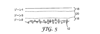
図5は、他の例示的な3ゾーン支持層の概略図であり、上部ゾーン18(ゾーン1)は、図4の上部ゾーン18(ゾーン1)と同一の機能性を提供し、即ちこれは薄フィルム支持ゾーンである。ゾーン2は、スクリム充填ゾーンを含み、その機能及び構造は図4のゾーン2と類似している。図5では、第3のゾーン20は、図6に提供するスロットダイ配置の図に示す方法で適用され、スクリム層12が提供され、スクリム層12にドープ(DAP2)が提供されてゾーン2/多孔質支持ゾーン16を形成し、ゾーン2/多孔質支持ゾーン16にドープ(DAP 3)が加えられて第3のゾーン20を形成し、第3のゾーン20にドープ(DAP 1)が加えられてゾーン1/上部ゾーン18(DAP 1)を形成する。「DAP」に対する参照は、米国特許第6,056,529号に述べられている熱操作に使用される「Dial−A−Pore(商標)」ユニットを意味する。ゾーン1は、スクリム充填層(ゾーン2)と薄フィルム支持層(ゾーン1)との間の十分な緩衝ゾーンを確実にする開放孔径ゾーンでもある。第3のゾーン20(ゾーン3)は、典型的にはその孔径がゾーン2の孔径に近い。
FIG. 5 is a schematic diagram of another exemplary three-zone support layer, where upper zone 18 (zone 1) provides the same functionality as upper zone 18 (zone 1) of FIG. A thin film support zone.
図7は、図4の変形である、他の例示的な2ゾーン支持層の概略図である。薄フィルム支持ゾーンは、ゾーン1である。第3のゾーンは存在しない。図4では、ゾーン2の成型は、薄フィルム支持ゾーン(ゾーン1)とスクリムとの間に小さい、無限に薄い公称緩衝ゾーンを提供するように表されている。図5では、薄フィルム支持ゾーン(ゾーン1)は、相当の及び制御された厚さの緩衝ゾーンによってスクリムから分離されている。図7では、緩衝ゾーンは、最小限に追いやられている。プロセスパラメーターの操作により、スクリム内へのゾーン2貫通の深さと、ゾーン1と補強スクリムとの間の緩衝ゾーンの厚さとの両方を同時に変更することが可能である。詳細には、緩衝ゾーンは最小化され得る。これは、質量流及び拡散流の両方が最適化された、装置製造のための最も薄い全体的な支持構造と、最大充填密度とを提供する。操作には、ドープ1及び2の粘度、単位面積当たりの総体積供給量、ウェブ張力に対する調整、ダイ間隙、並びにダイに対するウェブ接近角度が挙げられるが、これらに限定されない。
FIG. 7 is a schematic view of another exemplary two-zone support layer, which is a variation of FIG. The thin film support zone is
ゾーン2の機能は、スクリムの物理的機構中、及び前記機構の周囲に大孔径膜を形成することにより、スクリムに対して機械的アンカーを提供することである。ゾーン1は、(ゾーン1とゾーン2との)界面における、例えば、ナイロンポリマーの分子の絡み合いにより、ゾーン2に取り付けられる。ゾーン1の厚さは、典型的には50マイクロメートル未満であり、連続コーティングの限界までできるだけ薄くすることができ、それは2〜10マイクロメートルの範囲内である。図7では、この(ゾーン1とゾーン2との)界面の大部分は、スクリム上面の面の上方に配置されている。上述した操作により、この界面の位置を精密に制御して、全体の厚さと、全体の性能との間の最高のバランスを達成することが可能である。スクリムの少数の機構はゾーン1内に突出するが、全体の性能に対する実質的な効果は存在しないであろう。
The function of
その上に良好に制御された厚さのゾーンが通常のナイフスタイル成型手段によって計量供給され得る、完璧な又は平滑な成型表面を提供する成型スクリム(スクリムが無作為に置かれた繊維状材料又は高く構造化された設計材料のいずれであっても)は殆ど存在しないであろう。平滑ではない表面上に均一の厚さの連続コーティングを計量供給することは、スロットダイ成型システムの利点であるこの方法で、極めて多様な成型スクリム表面上に、可能な限り薄い連続ゾーン1層が実現され得る。ゾーン1の頂部上に薄フィルムナノ濾過又は工学的浸透層(1つ又は複数)に加えた場合でも、この方法により最も薄い全体構造が達成され得る。図8は、図7の実施形態のためのスロットダイ配置の図を提供し、スクリム層12が提供され、スクリム層12にドープ(DAP2)が提供されてゾーン2/多孔質支持ゾーン16を提供し、ゾーン2/多孔質支持ゾーン16にドープ(DAP1)が加えられてゾーン1/上部ゾーン18(DAP1)を形成する。図8では、DAP3は使用されていない。
A molded scrim that provides a perfect or smooth molding surface over which a zone of well-controlled thickness can be metered by conventional knife-style molding means (a fibrous material with randomly placed scrims or There will be very little (any of the highly structured design materials). It is an advantage of the slot die molding system to meter a continuous coating of uniform thickness on a non-smooth surface in this way, so that as thin a
好適な成型スクリムは通常、非常に小さい繊維から作製された非常に薄くかつ均一のウェブであり、その上に成型ポリマーが計量供給される幾分平滑な表面を提供する。螺旋状に巻き付けられた接線流カートリッジに使用されるスペーサ要素は、典型的には遙かにより厚いウェブであり、多くの場合、比較的太い繊維(例はTricotウェブである)、又は大きい開口を有する設計メッシュから作製された織布ウェブである。スペーサ要素の表面は平滑ではなく、このことは歴史的にそれらが、マイクロ濾過、NR、又は更にはRO膜の成型物の受容に使用されず、ここではグラビア、ナイフオーバーロール、ギャップベース方法などの方法が平滑表面において最高に働くことを意味していた。スペーサ要素は、スクリムよりも高価である。またスペーサ要素をポリマードープで満たして前記スペーサ要素をカートリッジ内に取り付け、また太い繊維間の大きい空間を全て架橋した場合、ギャップベース成型からのポリマードープコーティングは、非常に厚くならざるを得ず、これは費用及び得られる流束を増大させるであろう。 Suitable molded scrims are usually very thin and uniform webs made from very small fibers, providing a somewhat smooth surface on which the molded polymer is metered. Spacer elements used in helically wound tangential flow cartridges are typically much thicker webs, often with relatively thick fibers (eg Tricot webs), or large openings. A woven web made from a design mesh having. The surface of the spacer elements is not smooth, which means that historically they have not been used to accept microfiltration, NR or even RO membrane moldings, where gravure, knife over roll, gap based methods, etc. Means that it works best on smooth surfaces. Spacer elements are more expensive than scrims. Also, if the spacer element is filled with polymer dope and the spacer element is mounted in a cartridge, and all large spaces between thick fibers are cross-linked, the polymer dope coating from the gap base molding must be very thick, This will increase costs and the resulting flux.
図3、6、8、10及び米国特許第6,090,441号に示すスロットダイ技術を使用することにより、膜の成型物を受容するのにスペーサ要素を使用することが可能となり、これは、それらの技術が平滑表面を必要とせず、成型層の貫通の深さの容易な制御を提供し、また、イオン拒絶膜の支持のための可能な限り薄いゾーンを生成するためである。必要に応じて、ゾーン1及び2の厚さを調整して、多孔質支持層内でのスペーサ要素の使用に対処してもよい。
By using the slot die technique shown in FIGS. 3, 6, 8, 10 and US Pat. No. 6,090,441, it is possible to use spacer elements to receive the membrane molding, This is because these techniques do not require a smooth surface, provide easy control of the depth of penetration of the molded layer, and produce the thinnest possible zone for ion rejection membrane support. If necessary, the thickness of
螺旋状に巻き付けられた接線流カートリッジなどの装置、又は、通常流カートリッジ用の高密度プリーツ構造は、より薄い全体構造から利益を得、装置内の流体分配要素及びドレナージ/スペーサ要素の選択に最大の柔軟性を与えるであろう。スペーサ要素上に直接成型し、又は、上述したスクリム/多孔質支持ゾーン内にスペーサ要素の機能性を直接組み込むことが可能であり、得られた装置の更なる単純化、部品減少、及び費用低下が可能となる。 A device such as a spirally wound tangential flow cartridge or a high density pleated structure for a normal flow cartridge benefits from a thinner overall structure and maximizes the choice of fluid distribution and drainage / spacer elements within the device Would give you the flexibility. It is possible to mold directly on the spacer element or to incorporate the functionality of the spacer element directly into the scrim / porous support zone described above, further simplifying the resulting device, reducing parts and reducing costs Is possible.
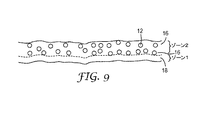
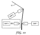
図9では、薄フィルム支持ゾーンは、ゾーン1として表される。ゾーン3は存在しない。ゾーン2の成型は、スクリムを完全に満たし、かつ過剰の成型で最小の層を提供する両方の方法で行われる。この最小の層は、多孔質支持ゾーン16の反対側に最小の緩衝ゾーンを提供する。図9では、薄フィルム支持ゾーンと支持ゾーンとの間の(ゾーン2とゾーン1との)界面の大部分が、スクリムの下面の面の直ぐ下に配置されている。スクリムの少数の機構は、ゾーン1内に突出するが、実質的な効果又は性能は存在しないであろう。ゾーン1層は、平滑ではない表面上の、均一の厚さの連続コーティングである。ゾーン1の厚さは、典型的には50マイクロメートル未満であり、連続コーティングの限界までできるだけ薄くすることができ、それは通常2〜10マイクロメートルの範囲内である。図10は、図9の実施形態のスロットダイ配置の図を提供し、スクリム層12が提供され、スクリム層12にドープ(DAP2)が提供されてゾーン2/多孔質ゾーン20を提供し、ゾーン2/多孔質ゾーン20にドープ(DAP1)が加えられてゾーン1/上部ゾーン18(DAP1)を形成する。図10では、DAP3は使用されていない。
In FIG. 9, the thin film support zone is represented as
薄フィルム複合膜構造
薄フィルム複合膜構造は、本明細書に開示した支持層を使用して、好適な薄フィルム選択膜層を取り付けることにより形成され得る。図19に、例示的な薄フィルム複合膜構造の概略図が提供される。イオン排除のための選択膜層(薄フィルム膜とも称される)19はゾーン1の部材18により支持され、次にゾーン1の部材18はゾーン2の部材16により支持される。
Thin Film Composite Membrane Structure A thin film composite membrane structure can be formed by attaching a suitable thin film selective membrane layer using the support layer disclosed herein. In FIG. 19, a schematic diagram of an exemplary thin film composite membrane structure is provided. A selective membrane layer (also referred to as a thin film membrane) 19 for ion exclusion is supported by the
特に注記がない限り、実施例及び明細書の残りの中の全ての部、百分率、比などは重量による。実施例の中で用いられる全ての試薬は、例えば、Sigma−Aldrich Company(Saint Louis,Mo.)などの一般化学品供給業者から購入したか、又は入手可能であるか、あるいは従来の方法によって合成してもよい。 Unless otherwise noted, all parts, percentages, ratios, etc. in the examples and the rest of the specification are by weight. All reagents used in the examples were purchased or available from general chemical suppliers such as, for example, Sigma-Aldrich Company (Saint Louis, Mo.) or synthesized by conventional methods. May be.
先行技術による薄フィルム支持体の疎水性が有する問題を軽減するために、図2による親水性精密濾過膜を薄フィルム支持体として使用して、従来のポリスルホン又はポリエーテルスルホン支持体を代替する。そのような膜の1つは、3Mから提供され、BLA010と称されており、このBLA010は、ナイロン6,6から作製され、多ゾーン構造を有する。3つの領域、1)大きい粒子を捕捉することによりプレフィルターとして、膜の上流側にあり、通常、精密濾過(MF)内で供給物に面する大孔領域、2)機械的支持体として使用され、かつ製造が容易な不織布スクリム、及び3)膜の下流側にあり、MF内で透過物に面して、小さい汚染物質を保持する小孔領域。小孔領域及び大孔領域の平均孔径は、それぞれ0.1μm及び0.45μmである。商用膜用のポリスルホン支持体と比較して、BLA010精密濾過膜は、遙かにより粗い、かつより開放された多孔質表面を有し、このことはより大きい浸透水流束をもたらし得る。ポリアミド選択膜層は、その場で界面重合を介して、最小孔側(孔が様々なサイズを有する場合)に構築される。本発明者らは、ナノ濾過膜(ピペラジン(PIP)系ポリアミドの界面重合により製作)及びRO膜(m−フェニレンジアミン(MPD)系ポリアミドを被覆することにより製作)の両方を作製する能力を示した。 In order to alleviate the problems with the hydrophobicity of the thin film support according to the prior art, the hydrophilic microfiltration membrane according to FIG. 2 is used as the thin film support, replacing the conventional polysulfone or polyethersulfone support. One such membrane is provided by 3M and is referred to as BLA010, which is made from nylon 6,6 and has a multi-zone structure. Three regions, 1) as a pre-filter by capturing large particles, upstream of the membrane, usually facing the feed in microfiltration (MF), 2) used as a mechanical support And a non-woven scrim that is easy to manufacture, and 3) a small pore area downstream of the membrane, facing the permeate in the MF and holding small contaminants. The average pore sizes of the small pore region and the large pore region are 0.1 μm and 0.45 μm, respectively. Compared to a polysulfone support for commercial membranes, BLA010 microfiltration membranes have a much rougher and more open porous surface, which can result in higher osmotic water flux. The polyamide selective membrane layer is built on the smallest pore side (if the pores have various sizes) via interfacial polymerization in situ. We show the ability to make both nanofiltration membranes (made by interfacial polymerization of piperazine (PIP) based polyamide) and RO membranes (made by coating m-phenylenediamine (MPD) based polyamide). It was.
ジアミンモノマーピペラジン(PIP)及びm−フェニレンジアミン(MPD)は、それぞれAcros Organic及びSigma−Aldrichから購入した。酸塩化物モノマー塩化トリメソイル(TMC)及び酸受容体トリエチルアミン(TEA)は、Sigma−Aldrichから購入した。ヘキサン、TMC用の溶媒は、Fisher Scientificから購入した。Milli−Q超純水精製システム(Millipore,Billerica,MA)から得た脱イオン水(DI)を、ジアミンモノマー用の溶媒として使用した。塩化ナトリウム及び硫酸マグネシウムは、Fisher Scientificから購入した。 The diamine monomers piperazine (PIP) and m-phenylenediamine (MPD) were purchased from Acros Organic and Sigma-Aldrich, respectively. Acid chloride monomers trimesoyl chloride (TMC) and acid acceptor triethylamine (TEA) were purchased from Sigma-Aldrich. Solvents for hexane and TMC were purchased from Fisher Scientific. Deionized water (DI) obtained from a Milli-Q ultrapure water purification system (Millipore, Billerica, MA) was used as the solvent for the diamine monomer. Sodium chloride and magnesium sulfate were purchased from Fisher Scientific.
(実施例1)
PIP系ポリアミドの界面重合による、これらTFC膜構造の製作を示すための手順は、以下の通りであった。
Example 1
The procedure for showing the fabrication of these TFC membrane structures by interfacial polymerization of PIP-based polyamide was as follows.
このポリ(ピペラジンアミド)のその場で界面重合に使用したモノマーは、PIP及びTMCであった。PIPを0.25%〜3%(w/v)の範囲の様々な濃度でMilli−Q水に溶解した。PIP量に対して1/1の重量比のトリエチルアミン(TEA)をPIP水性溶液に加えた。塩化トリメソイル(TMC)の0.15%(w/v)ヘキサン溶液を調製した。使用前に、両方の溶液を室温で最短3時間撹拌した。 The monomers used for in situ interfacial polymerization of this poly (piperazine amide) were PIP and TMC. PIP was dissolved in Milli-Q water at various concentrations ranging from 0.25% to 3% (w / v). A 1/1 weight ratio of triethylamine (TEA) to the amount of PIP was added to the aqueous PIP solution. A 0.15% (w / v) hexane solution of trimesoyl chloride (TMC) was prepared. Prior to use, both solutions were stirred at room temperature for a minimum of 3 hours.
BLA010ナイロン6,6精密濾過(MF)膜/支持層を平坦なガラスプレート上に、大孔側がガラスプレートに面するように配置し、全部の縁をテープで密封した。MF膜を最初に水性PIP/TEA溶液中に2分間浸した。MF膜は、プレートの後面が溶液中に浸されないように、溶液中に配置された。2分後、プレートを溶液から取り除き、過剰の溶液を表面から流し出した。次いで、プレートを、ガラスを下にして支持体が上を向くようにゴムマット上に配置し、ゴムローラーを使用して、支持膜から過剰の溶液を除去した。次いで、支持膜を特注製作の350mL容器内のTMC/ヘキサン溶液中に垂直に1分間漬けて、薄フィルムポリ(ピペラジンアミド)フィルムを形成した。得られた複合フィルムを2分間風乾し、続いて、形成された構造の所望の安定性を得るために、空気循環炉内にて80℃で5分間硬化させた。調製したままの薄TFCポリ(ピペラジンアミド)膜構造を徹底的に洗浄し、評価試験を行う前に、脱イオン水中にて4℃で貯蔵した。 A BLA010 nylon 6,6 microfiltration (MF) membrane / support layer was placed on a flat glass plate with the large pore side facing the glass plate, and all edges were sealed with tape. The MF membrane was first immersed in an aqueous PIP / TEA solution for 2 minutes. The MF membrane was placed in the solution so that the back side of the plate was not immersed in the solution. After 2 minutes, the plate was removed from the solution and excess solution was flushed from the surface. The plate was then placed on a rubber mat with the glass facing down and the support facing up, and a rubber roller was used to remove excess solution from the support membrane. The support membrane was then immersed vertically in a TMC / hexane solution in a custom-made 350 mL container for 1 minute to form a thin film poly (piperazine amide) film. The resulting composite film was air dried for 2 minutes and then cured at 80 ° C. for 5 minutes in an air circulating oven to obtain the desired stability of the formed structure. The as-prepared thin TFC poly (piperazine amide) membrane structure was thoroughly washed and stored at 4 ° C. in deionized water prior to evaluation testing.
MPD系ポリアミドの界面重合のための手順は、水性溶液が水中の025%〜3%(w/v)の範囲の様々な濃度の純粋MPDであった以外は、PIP系ポリアミドの手順と同様であった。 The procedure for the interfacial polymerization of MPD-based polyamides is similar to the procedure for PIP-based polyamides, except that the aqueous solution was various concentrations of pure MPD ranging from 025% to 3% (w / v) in water. there were.
これらのプロセスは、現存する界面重合の方法と類似しているため、大規模製作に容易に拡大される。 Since these processes are similar to existing methods of interfacial polymerization, they are easily extended to large scale fabrication.
(実施例2)
比較
商用非対称三酢酸セルロース(HTI−CTA)正浸透(FO)膜(Hydration Technology Innovations Inc.,Albany,OR)、TFCナノ濾過膜NF270及びTFC seawater RO膜SW30−XLE(Dow Water & Process Solutions Company,Midland,MI)を、比較のために得た。これらの膜は、3つの層:ポリアミド選択的薄フィルム層、マイクロ多孔質ポリスルホン(PSu)中間層、及び高強度ポリエステル支持ウェブを有する。
(Example 2)
Comparison Commercial Asymmetric Cellulose Triacetate (HTI-CTA) Forward Osmosis (FO) Membrane (Hydration Technology Innovations Inc., Albany, OR), TFC Nanofiltration Membrane NF270 and TFC seawater RO Membrane SW30-XLE (Dow Water Coat Soil Proceed Proceed Midland, MI) was obtained for comparison. These membranes have three layers: a polyamide selective thin film layer, a microporous polysulfone (PSu) interlayer and a high strength polyester support web.
(実施例3A)
実験方法論
BLA010 MF支持体及びTFCポリアミド膜の表面形態を、冷陰極電界放出型走査型電子顕微鏡JSM−6335F(FEI Company,USA)を使用した走査型電子顕微鏡法(SEM)により、定性的に評価した。撮像の前に、サンプルを一晩デシケータ内に保ち、その後、白金の薄層でスパッター被覆してより良好なコントラストを得、また帯電を回避した。
(Example 3A)
Experimental Methodology Qualitative evaluation of surface morphology of BLA010 MF support and TFC polyamide membrane by scanning electron microscopy (SEM) using cold cathode field emission scanning electron microscope JSM-6335F (FEI Company, USA) did. Prior to imaging, the samples were kept in a desiccator overnight and then sputter coated with a thin layer of platinum to obtain better contrast and avoid charging.
BLA010 MF支持体及びTFCポリアミド膜の表面形態を、冷陰極電界放出型走査型電子顕微鏡JSM−6335F(FEI Company,USA)を使用した走査型電子顕微鏡法(SEM)により、定性的に評価した。撮像の前に、サンプルを一晩デシケータ内に保ち、その後、白金の薄層でスパッター被覆してより良好なコントラストを得、また帯電を回避した。 The surface morphology of the BLA010 MF support and the TFC polyamide membrane was qualitatively evaluated by scanning electron microscopy (SEM) using a cold cathode field emission scanning electron microscope JSM-6335F (FEI Company, USA). Prior to imaging, the samples were kept in a desiccator overnight and then sputter coated with a thin layer of platinum to obtain better contrast and avoid charging.
TFC膜のBLA010支持体及び選択層の断面構造もSEMにより撮像した。これらのサンプルは、液体窒素を含む凍結破断法を用いる撮像用に調製した。補強不織布スクリムを凍結破断することは困難なため、かみそりの刃もサンプルストリップと共に同時に液体窒素中に沈めた後、液体窒素から除去した後、サンプルを半分に迅速に切断するのに使用した。調製したサンプルを、撮像前に、金の薄層を用いてスパッター被覆した。 The cross-sectional structure of the TFC membrane BLA010 support and selective layer was also imaged by SEM. These samples were prepared for imaging using a freeze fracture method containing liquid nitrogen. Because it was difficult to freeze-break reinforced nonwoven scrims, a razor blade was also submerged in liquid nitrogen simultaneously with the sample strip and then used to quickly cut the sample in half after removal from liquid nitrogen. The prepared sample was sputter coated with a thin layer of gold before imaging.
支持体の厚さを、各膜サンプルに関して5つの異なる位置で、デジタルマイクロメーターを使用して測定した。CAM 101シリーズ接触角角度計を使用して、支持体の接触角を測定した。 The thickness of the support was measured using a digital micrometer at five different locations for each membrane sample. The contact angle of the support was measured using a CAM 101 series contact angle goniometer.
異なるPIP濃度で作製したポリ(ピペラジンアミド)TFC膜に関する純水透過性(A)を、DIを供給物として使用して評価した。純水透過性試験は、25℃で0.26m/sのクロスフロー速度で、50〜250psi(0.34〜1.72MPa)の範囲の4つの圧力下で行った。ポリ(ピペラジンアミド)TFC膜に関する塩排除評価を、DI水の代わりに2000ppm MgSO4を供給物として使用した以外は、同様の方法で行った。バルク透過物及び供給物の導電性を測定することにより、観察された塩排除率(%R)を特徴付けた。 Pure water permeability (A) for poly (piperazine amide) TFC membranes made with different PIP concentrations was evaluated using DI as the feed. The pure water permeability test was conducted at 25 ° C. with a cross flow rate of 0.26 m / s under four pressures ranging from 50 to 250 psi (0.34 to 1.72 MPa). Salt exclusion assessments for poly (piperazine amide) TFC membranes were performed in a similar manner except that 2000 ppm MgSO 4 was used as the feed instead of DI water. The observed salt rejection (% R) was characterized by measuring the conductivity of the bulk permeate and the feed.
ポリアミドTFC膜に関する純水透過性及び塩排除試験を、DI及び2000ppm NaClを供給物として使用して、それぞれ150〜300psi(1.03〜2.07MPa)の範囲の4つの圧力下で行った。SW30−XLEを対照として使用した。他の試験条件は、ポリ(ピペラジンアミド)に関する条件と同一に保つ。 Pure water permeability and salt exclusion tests on polyamide TFC membranes were performed under four pressures ranging from 150 to 300 psi (1.03 to 2.07 MPa), respectively, using DI and 2000 ppm NaCl as feed. SW30-XLE was used as a control. Other test conditions are kept the same as for poly (piperazine amide).
本発明者らの最適ポリアミドTFC膜の純水透過性及び塩排除率は、20℃で商用FO膜とも比較し、20℃で浸透流束(osmotic flux)試験を行った。溶質透過性係数、Bも決定して、構造パラメーター、Sを計算した。 The optimum water permeability and salt rejection rate of our optimum polyamide TFC membrane were compared with a commercial FO membrane at 20 ° C. and an osmotic flux test was conducted at 20 ° C. The solute permeability coefficient, B, was also determined and the structural parameter, S, was calculated.
純水透過性、Aは、純水流束(Jw)を適用圧力(ΔP)、A=Jw/ΔPで除算することにより決定した。塩排除率、%Rは、導電率計を使用して測定したバルク供給物(cf)及び透過物(cp)の塩濃度における差異から決定した。 The pure water permeability, A, was determined by dividing the pure water flux (J w ) by the applied pressure (ΔP), A = J w / ΔP. The salt rejection,% R, was determined from the difference in the salt concentration of the bulk feed (cf) and permeate (cp) measured using a conductivity meter.
溶質透過性係数、Bは、 Solute permeability coefficient, B is

ポリアミドTFC膜の浸透水流束及び逆塩流束を、特注の実験室規模クロスフロー正浸透システムを使用して評価した。1.5M塩化ナトリウム溶液を誘導溶液として使用すると共に、DI水を供給溶液として使用した。PROモード(膜活性層が誘導溶液に面する)及びFOモード(膜活性層が供給溶液に面する)の両方の配向の膜を使用して浸透流束試験を行った。供給及び誘導溶液の水圧は同一(1.5psi(0.010MPa))であり、供給及び誘導溶液の両方のクロスフロー速度を0.18m/sに保った。再循環水浴及び熱交換器を使用して、供給及び誘導溶液の温度を20±1℃に維持した。供給物の導電性を測定して、膜を通した逆塩流束を概算した。 The osmotic water flux and reverse salt flux of the polyamide TFC membrane were evaluated using a custom-made laboratory scale crossflow forward osmosis system. 1.5M sodium chloride solution was used as the induction solution and DI water was used as the feed solution. Osmotic flux tests were performed using membranes in both PRO mode (membrane active layer facing the induction solution) and FO mode (membrane active layer facing the feed solution). The water pressure of the feed and induction solution was the same (1.5 psi (0.010 MPa)) and the cross flow rate of both the feed and induction solution was kept at 0.18 m / s. A recirculating water bath and heat exchanger were used to maintain the temperature of the feed and induction solutions at 20 ± 1 ° C. The conductivity of the feed was measured to approximate the reverse salt flux through the membrane.
浸透水流束、Jwは、体積流束を膜面積で除算して計算した、試験中、所定の時点で供給溶液の導電性を測定することにより、逆塩流束、Jsを、NaCl質量流量を膜面積で除算して計算した。 The osmotic water flux, J w, was calculated by dividing the volumetric flux by the membrane area. During the test, the reverse salt flux, J s , NaCl mass was measured by measuring the conductivity of the feed solution at a given time point during the test. The flow rate was calculated by dividing by the membrane area.
比塩流束、Js/Jw、を、逆塩流束と水流束との比として決定した。構造パラメーターは、等式 The specific salt flux, J s / J w , was determined as the ratio of reverse salt flux to water flux. Structural parameters are equal
(実施例3B)
実験結果
図11に、ナイロン6,6 MF支持体(BLA010)の表面及び断面SEM像を示す。小孔領域及び大孔領域の両方の表面は、粗い、かつ開放した多孔質形態を示す。2つのゾーンの表面多孔率は、それぞれ51.1%及び48.4%である。支持体の平均厚さは181.4±1.1μmと測定され、支持体の接触角はおよそ40.5度であり、これは従来のTFC PSu支持体よりも40〜50度小さい。
(Example 3B)
Experimental Results FIG. 11 shows a surface and a cross-sectional SEM image of a nylon 6,6 MF support (BLA010). The surfaces of both the small and large pore areas exhibit a rough and open porous morphology. The surface porosity of the two zones is 51.1% and 48.4%, respectively. The average thickness of the support is measured as 181.4 ± 1.1 μm, and the contact angle of the support is approximately 40.5 degrees, which is 40-50 degrees smaller than a conventional TFC PSu support.
これらの膜は、典型的には、MF中、より大きい孔が供給物に面するように配向される一方、TFC膜の選択層は、小孔径上に構築されている。小孔領域によって、より欠陥の少ない完全な選択層の形成が可能となると共に、大孔ゾーンは物質移動に対する抵抗を低減する。 These membranes are typically oriented in MF so that the larger pores face the feed, while the selective layer of the TFC membrane is built on a small pore size. The small pore area allows the formation of a complete selective layer with fewer defects and the large pore zone reduces resistance to mass transfer.
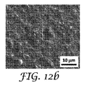
図12に、異なるPIP濃度で作製したポリ(ピペラジンアミド)選択層の上面SEM像を示す。無欠陥フィルムは、0.25〜3%の範囲の全PIP濃度にて作製されたTFC膜に関して得られた。表面形態は、PIP濃度により変動した。「円形状」形態は0.25%及び0.5% PIP系TFC膜上に観察できる一方、より均一の凹凸構造が1.0%及び2.0% PIPを使用した際に現れた。これらの凹凸は、より低いPIP濃度がより薄いフィルムを提供するため、粗い支持層から生じ得る。3.0% PIP系膜の場合、選択層は支持体の機構を完全に覆って、凹凸構造が消失したように思われる。一般に、PIP系TFC膜は、商用NF270よりも粗い表面を与えた。 FIG. 12 shows top SEM images of poly (piperazine amide) selective layers made with different PIP concentrations. Defect-free films were obtained for TFC membranes made with total PIP concentrations in the range of 0.25 to 3%. The surface morphology varied with PIP concentration. “Circular” morphology can be observed on 0.25% and 0.5% PIP-based TFC membranes, while a more uniform relief structure appeared when using 1.0% and 2.0% PIP. These irregularities can arise from a rough support layer because lower PIP concentrations provide a thinner film. In the case of a 3.0% PIP-based membrane, the selective layer completely covered the mechanism of the support, and the concavo-convex structure seems to have disappeared. In general, PIP-based TFC membranes gave a rougher surface than commercial NF270.
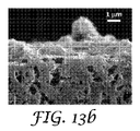
図13に、異なるPIP濃度で作製されたポリ(ピペラジンアミド)選択層に関する断面SEM像を示す。表1に、PIP濃度の関数としての、対応する厚さを示す。 FIG. 13 shows cross-sectional SEM images for poly (piperazine amide) selective layers made with different PIP concentrations. Table 1 shows the corresponding thickness as a function of PIP concentration.
1マイクロメートル未満の厚さを有する極薄ポリ(ピペラジンアミド)層が得られた。選択層の厚さは、最初、PIP濃度が2%まで上昇すると共に序々に増大し、その後、3% PIPにおいて0.9マイクロメートルに劇的に増大した。3% PIPにおいて、ポリ(ピペラジンアミド)選択層は支持体から剥離するように思われたことに留意することも重要である。一方、より低いPIP濃度(即ち、1%未満)で作製された得られたTFC選択層は、支持体とより良好に一体化され、支持体とのより良好な接着を示す。 An ultrathin poly (piperazine amide) layer having a thickness of less than 1 micrometer was obtained. The thickness of the selective layer initially increased gradually with increasing PIP concentration to 2%, and then dramatically increased to 0.9 micrometers at 3% PIP. It is also important to note that at 3% PIP, the poly (piperazine amide) selective layer appeared to delaminate from the support. On the other hand, the resulting TFC selective layer made at a lower PIP concentration (ie, less than 1%) is better integrated with the support and exhibits better adhesion to the support.
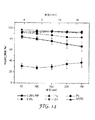
図14は、PIP濃度の関数としての、PIP系TFC膜に関するMgSO4排除率を示す。排除率は、フィルムの密度の増大に起因して、2%までPIP濃度の増大と共に上昇した後、予想外に3%で低下した。3% PIP選択層に関するこの劇的な性能低下は、SEM像における選択層の、観察された剥離に起因し得る(図13)。0.25%及び0.5% PIP系膜に関する排除は、水圧の上昇と共に低下することも分かり、得られたフィルムが、より高圧下でより柔軟及び/又は脆弱となることを示している。しかしながら、1%及び2% PIP系TFC膜の排除率は、一連の水圧に亘って95%を超えて維持し、これはNF270の排除性能に接近した。TFC膜の良好な圧力耐性は、プレッシャーリターデッドオスモシスへのそれらの適用の可能性も示唆している。 FIG. 14 shows the MgSO 4 rejection for PIP-based TFC membranes as a function of PIP concentration. The rejection rate rose unexpectedly at 3% after increasing with increasing PIP concentration to 2% due to increased film density. This dramatic performance degradation for the 3% PIP selective layer can be attributed to the observed delamination of the selective layer in the SEM image (FIG. 13). The exclusion for 0.25% and 0.5% PIP-based membranes has also been found to decrease with increasing water pressure, indicating that the resulting film becomes more flexible and / or fragile under higher pressures. However, the rejection rates of the 1% and 2% PIP-based TFC membranes remained above 95% over a series of water pressures, which approached the NF270 exclusion performance. The good pressure resistance of TFC membranes also suggests their potential application in pressure retarded osmosis.
表2は、PIP系TFC膜の純水透過性を示す。透水性は、選択層の厚さの増大に起因して、PIP濃度の増大と共に低下した。商用NF270と比較すると、1% PIP系TFC膜は、同様の排除率を示したのみでなく、一致した水流束も示した。TFC膜の全体的性能は、工業規格の商用NF膜の全体的性能と一致した。 Table 2 shows the pure water permeability of the PIP TFC membrane. Water permeability decreased with increasing PIP concentration due to increased thickness of the selective layer. Compared to commercial NF270, the 1% PIP-based TFC membrane not only showed similar rejection, but also showed consistent water flux. The overall performance of the TFC membrane was consistent with the overall performance of the industry standard commercial NF membrane.
図15に、異なるMPD濃度で作製したポリアミド選択層の上面SEM像を示す。凹凸構造を有する無欠陥フィルムは、0.25〜3%の範囲の全MPD濃度で作製されたTFC膜に関して得られた。TFC膜の選択層の全部は、商用SW30−XLE膜よりも粗いように見えた。 FIG. 15 shows SEM images of the upper surface of the polyamide selective layer prepared with different MPD concentrations. A defect-free film having a concavo-convex structure was obtained for a TFC film made with a total MPD concentration in the range of 0.25-3%. All of the selective layers of the TFC membrane appeared to be rougher than the commercial SW30-XLE membrane.
図16に、異なるMPD濃度で作製したポリアミド選択層の断面SEM像を示す。表3に、MPD濃度の関数としての、対応する測定されたポリアミド層の厚さを示す。 FIG. 16 shows cross-sectional SEM images of polyamide selective layers prepared with different MPD concentrations. Table 3 shows the corresponding measured polyamide layer thickness as a function of MPD concentration.
厚さは、MPD濃度の増大と共に僅かに増大した(MPD濃度の範囲に亘っておよそ50nm)。これは、モノマー濃度により高い厚さ依存性を有したポリ(ピペラジンアミド)とは異なる結果である。これは2つのアミンの拡散性及びTMCとの反応速度論(reacting kinetics)における差異に起因する。界面重合は、3つの工程にて行われるよう説明される。初期のフィルム形成、急速なプロセス、その後の形成された初期フィルムの透過性に応じた、重合の減速、最終的な拡散制御プロセスへの移動。初期のフィルム形成中に形成される初期層は、実際のバリア層である。次いで、モノマー拡散の限界が開始するまで、フィルム成長が行われる。反応の終結は、ジアミン拡散の減速と、重合と競合する、酸塩化物の加水分解とにより説明される。MPD系ポリアミドの場合、MPDが低濃度のとき(≦0.5%)、MPD濃度を0.5%まで増大させることにより、0.15% TMC濃度に対応する最大厚さを有するバリア層の形成をもたらすことが可能である。MPD濃度を更に増大させることにより、アミノ末端基に富んだ薄フィルム領域内でMPDの幾分かの蓄積がもたらされ得る。このことは、フィルム厚さがこの段階では殆ど不変のままであるため、薄フィルムの密度を増大させ得る。しかしながら、PIPはMPDよりも遙かにゆっくりとTMCと反応するため、より高いPIP濃度の下で比較的厚いバリア層を形成するのにはより長時間を要するであろう。更に、酸受容体の添加は反応中に形成された殆どの酸塩化物を消費し、このことは重合の完了を延期し得る。 The thickness increased slightly with increasing MPD concentration (approximately 50 nm over a range of MPD concentrations). This is a different result from poly (piperazine amide), which has a higher thickness dependence on monomer concentration. This is due to differences in the diffusivity of the two amines and the reacting kinetics with TMC. Interfacial polymerization is described as being performed in three steps. Initial film formation, rapid process, subsequent slowing of polymerization depending on the permeability of the initial film formed, transfer to final diffusion control process. The initial layer formed during the initial film formation is the actual barrier layer. Film growth is then performed until the limit of monomer diffusion begins. The termination of the reaction is explained by the slowing of diamine diffusion and the hydrolysis of the acid chloride, which competes with the polymerization. In the case of MPD-based polyamides, when the MPD is low (≦ 0.5%), the MPD concentration is increased to 0.5% to increase the barrier layer having the maximum thickness corresponding to 0.15% TMC concentration. It is possible to bring about formation. Further increasing the MPD concentration can result in some accumulation of MPD within the thin film region rich in amino end groups. This can increase the density of the thin film because the film thickness remains almost unchanged at this stage. However, since PIP reacts with TMC much more slowly than MPD, it will take longer to form a relatively thick barrier layer under higher PIP concentrations. Furthermore, the addition of the acid acceptor consumes most of the acid chloride formed during the reaction, which can postpone the completion of the polymerization.
図17に、MPD濃度の関数としての、MPD系TFC膜に関するNaCl排除率を示す。0.25% MPD系TFC膜の排除率は、薄い選択層の低い機械的強度に起因して、300psi(2.06MPa)にて劇的に低下した。PIP系TFC膜と同様、これらの膜の塩排除は、MPD濃度(2% MPDまで)と共に増大した。これは、より密なポリアミド層の形成をもたらす、架橋密度の向上によるものであった。また、ポリアミドの鎖屈曲性は、MPDの濃度の増大と共に低下し得る。3% MPDにおける排除率は、塩流束の希釈を低減する、水流束の低下に起因した可能性がある。「希釈効果」が示唆するように、高い浸透液流束は、膜を交差する塩を希釈し、これは次に塩排除率を増大させる。商用SW30−XLEと比較すると、1%及び2%のMPD系TFC膜は、一致した排除率を示し、排除率は95%超で維持された。これらはまた、排除性能を損なうことなく、少なくとも300psi(2.06MPa)の水圧に耐えることができ、これはプレッシャーリターデッドオスモシスに好適であり得ることを意味することに留意することが重要である。 FIG. 17 shows the NaCl rejection rate for MPD-based TFC membranes as a function of MPD concentration. The rejection of the 0.25% MPD-based TFC membrane dropped dramatically at 300 psi (2.06 MPa) due to the low mechanical strength of the thin selective layer. Similar to PIP-based TFC membranes, the salt rejection of these membranes increased with MPD concentration (up to 2% MPD). This was due to the increased crosslink density that resulted in the formation of a denser polyamide layer. Also, the chain flexibility of polyamide can decrease with increasing MPD concentration. The rejection rate at 3% MPD may be due to a decrease in water flux, which reduces salt flux dilution. As the “dilution effect” suggests, high permeate flux dilutes salt across the membrane, which in turn increases salt rejection. Compared to commercial SW30-XLE, the 1% and 2% MPD-based TFC membranes showed consistent rejection rates and the rejection rates were maintained above 95%. It is important to note that they can also withstand water pressures of at least 300 psi (2.06 MPa) without compromising rejection performance, which means that they can be suitable for pressure retarded osmosis. is there.
表4も、MPD系TFC膜の純水透過性を商用SW30−XLEと比較する。PIP系TFC膜と同様、MPD濃度の増大は、ポリアミドフィルムの架橋密度の増大と鎖屈曲性の低下に起因して、水流束の低下をもたらした。商用SW30−XLEと比較すると、1% MPDは、得られたTFC膜が卓越した排除率を示したのみでなく比較的高い水流束も示したため最適濃度であると思われ、商用sea water RO膜の性能に接近した。 Table 4 also compares the pure water permeability of the MPD TFC membrane with commercial SW30-XLE. As with the PIP-based TFC membrane, the increase in MPD concentration resulted in a decrease in water flux due to an increase in the crosslink density of the polyamide film and a decrease in chain flexibility. Compared to commercial SW30-XLE, 1% MPD is considered to be the optimal concentration because the resulting TFC membrane not only showed excellent rejection but also showed a relatively high water flux, and commercial sea water RO membrane Approached the performance.
クロスフロー逆浸透試験は、1% PIP及び1% MPD系TFC膜が、それぞれ商用NF270及びSW30−XLEの性能に接近し、したがって最適サンプルと見なされることを明かにした。誘導溶液として1.5M NaClを使用する浸透流束試験を、1% MPD系TFC膜(TFC−EOと称する)上で行い、商用HTI−CTA膜(HTIと称する)を対照として使用した。 Cross-flow reverse osmosis testing revealed that 1% PIP and 1% MPD-based TFC membranes approach the performance of commercial NF270 and SW30-XLE, respectively, and are therefore considered the optimal sample. An osmotic flux test using 1.5M NaCl as the induction solution was performed on a 1% MPD-based TFC membrane (referred to as TFC-EO) and a commercial HTI-CTA membrane (referred to as HTI) was used as a control.
図18Aは、TFC−EO及び商用FO膜の両方の浸透水流束性能を表す。TFC−EO膜はPROモードにおいてHTIよりも高い水流束を提供したことが理解され得る。これは主に、TFC膜の、より高い透過選択性に起因する。表5から理解し得るように、TFC−EO膜は、HTI FO膜と比較して高い透水性係数と、低い溶質透過性とを有する。 FIG. 18A represents the osmotic water flux performance of both TFC-EO and commercial FO membranes. It can be seen that the TFC-EO membrane provided a higher water flux than HTI in the PRO mode. This is mainly due to the higher permselectivity of the TFC membrane. As can be seen from Table 5, the TFC-EO membrane has a higher water permeability coefficient and lower solute permeability compared to the HTI FO membrane.
TFC膜が一般に、それらのポリアミドの極薄い、密な架橋構造により、非対称膜よりも高い透過選択性を有するため、この観測結果は予想される。より低い溶質透過性により誘導溶液から交差する塩が低減され、これは内部濃度分極(ICP)を誘導する。DIを供給物として有するPROモードでは、選択層を交差する溶質のみがICPを誘導し得るため、流束性能は膜の排除能力に大きく依存する。FOモードでは、支持体が誘導溶液に面した際に生じる、より深刻なICPに起因して、TFC−EO及び商用HTI膜の両方が、PROモードでの水流束と比較して小さい水流束を示した。更に、FOモードでは、TFC−EO膜は支持体として使用した3M膜の厚さに主に起因して(およそ50μmと比較して180μm)、HTI膜よりも僅かに小さい水流束を示した。より厚い支持体は、ICPを増大させ、一般にFO膜には所望されない。興味深いことに、ナイロン6,6支持体は、HTI膜支持体の厚さを3倍上回るが、尚、水流束性能はほぼ等しい。図18Bに、TFC−EO及びHTI膜の両方に関する逆塩流束性能を示す。PRO及びFOモードの両方において、TFC膜は、HTIのおよそ10倍小さい逆塩流束を示し、これは主に一体化非対称膜よりも高いTFC膜の選択性に起因する。FOモードにおける両方の膜に関する逆塩通過は、PROモードよりも僅かに低かった。これは主に、塩の濃度差がFOモードと比較してより大きく、したがってPROモードでは選択層界面での駆動力が有効であったことに起因する。全体として、全試験において、膜は一貫した性能を有し、高濃度の塩の存在により変化しないことを示した。試験中、選択層の剥離は観察されなかった。 This observation is expected because TFC membranes generally have higher permselectivity than asymmetric membranes due to their ultra-thin, dense cross-linked structure. Lower solute permeability reduces salt crossing from the induction solution, which induces internal concentration polarization (ICP). In the PRO mode with DI as the feed, only the solute that crosses the selected layer can induce ICP, so the flux performance is highly dependent on the membrane's exclusion capability. In FO mode, due to the more severe ICP that occurs when the support faces the induction solution, both TFC-EO and commercial HTI membranes have a small water flux compared to the water flux in PRO mode. Indicated. Furthermore, in the FO mode, the TFC-EO membrane exhibited a slightly lower water flux than the HTI membrane, mainly due to the thickness of the 3M membrane used as the support (approximately 180 μm compared to approximately 50 μm). Thicker supports increase ICP and are generally not desired for FO membranes. Interestingly, the nylon 6,6 support exceeds the thickness of the HTI membrane support by a factor of 3, but still has approximately the same water flux performance. FIG. 18B shows the reverse salt flux performance for both TFC-EO and HTI membranes. In both the PRO and FO modes, the TFC membrane exhibits an inverse salt flux that is approximately 10 times smaller than the HTI, mainly due to the higher TFC membrane selectivity than the integrated asymmetric membrane. The reverse salt passage for both membranes in FO mode was slightly lower than in PRO mode. This is mainly due to the fact that the salt concentration difference is larger than that in the FO mode, and therefore the driving force at the interface of the selective layer is effective in the PRO mode. Overall, in all tests, the membranes showed consistent performance and did not change due to the presence of high concentrations of salt. No peeling of the selective layer was observed during the test.
この新しいTFC−EO膜が、塩流束の同一の桁の大きさで、PROモードにおける同様の実験条件下での他の試験で報告された商用TFC−RO膜(SW30−XLE)と比較して、およそ20倍の水流束を提供したことは言及する価値がある。TFC−EO膜はSW30−XLEと同様の排除率及び純水透過性を示したため、水流束の劇的な改善は、支持体内のICPの低下に起因する筈である。理論に束縛されるものではないが、このナイロン6,6支持体に関するICPの低下は、その構造よりはその親水性に起因すると考えられる。Dow FilmTec RO膜に関するPSu支持体は、一般に、ナイロン6,6支持体(〜180μm及びおよそ50〜60%の多孔率)と同等の厚さ(〜150μm)及び多孔率(およそ50%)を有する。この層の改善された濡れは、有効な構造パラメーターを劇的に低下させ、浸透流束を改善するであろう。更に、同様に理論に束縛されるものではないが、選択層との界面における3M支持体の表面多孔率がより高いことは、選択層が選択層により遮断されていないため、水流束を改善すると考えられる。支持体により妨害されない選択層が多くなると、界面から離れる水及び塩の両方の輸送が促進される。この支持体の表面多孔率はおよそ50%と測定されたが、商用RO膜の表面多孔率は、20%未満と報告されている。 This new TFC-EO membrane is compared to the commercial TFC-RO membrane (SW30-XLE) reported in other tests under the same experimental conditions in PRO mode with the same order of magnitude of salt flux. It is worth mentioning that it provided approximately 20 times the water flux. Since the TFC-EO membrane showed similar rejection and pure water permeability as SW30-XLE, the dramatic improvement in water flux should be due to the decrease in ICP within the support. Without being bound by theory, it is believed that the decrease in ICP for this nylon 6,6 support is due to its hydrophilicity rather than its structure. PSu supports for Dow FilmTec RO membranes generally have a thickness (˜150 μm) and porosity (approximately 50%) comparable to nylon 6,6 supports (˜180 μm and approximately 50-60% porosity) . Improved wetting of this layer will dramatically reduce the effective structural parameters and improve osmotic flux. Furthermore, although not bound by theory as well, the higher surface porosity of the 3M support at the interface with the selective layer improves the water flux because the selective layer is not blocked by the selective layer. Conceivable. The more selective layers that are not disturbed by the support, facilitate the transport of both water and salt away from the interface. The surface porosity of this support was measured to be approximately 50%, while the surface porosity of commercial RO membranes has been reported to be less than 20%.
表5はまた、TFC膜とHTI膜との間の比塩流束及び構造パラメーターの比較をまとめる。比塩流束は、生成された水1リットル当たりの誘導溶質損失の量を表す。比塩流束は誘導溶質の損失を低減するよう可能な限り小さい必要がある。表から、HTI膜と比較した際、TFC−EO膜は、PROモードでは28倍小さい、FOモードでは8倍小さい比塩流束を有したことが理解され得る。これらの結果は、TFC−EO膜がFOでは誘導溶液を節約し、PROではICPの低下を有することを示す。 Table 5 also summarizes the comparison of specific salt flux and structural parameters between TFC and HTI membranes. Specific salt flux represents the amount of induced solute loss per liter of water produced. The specific salt flux should be as small as possible to reduce the loss of induced solute. From the table, it can be seen that when compared to the HTI membrane, the TFC-EO membrane had a specific salt flux that was 28 times smaller in the PRO mode and 8 times smaller in the FO mode. These results indicate that the TFC-EO membrane saves induction solution with FO and has reduced ICP with PRO.
新しいFO膜の特徴付けに一般的なように、構造パラメーター、Sは、浸透流束試験から計算することができる。構造パラメーターは、ICF効果がいかに深刻であるか、また水流束を最大にするために可能な限り小さい必要があることを示唆する。表5は、TFC−EO膜が、商用HTI膜の2倍の構造パラメーターを有することを示す。これは、TFC膜内のより厚い支持体に大きく起因する。この結果は、膜を通した水流束がHTI膜と一致し又は超えたことを考えると興味深かった。このことは更に、支持層の特性及び選択性の両方が、浸透水流束性能に実質的に影響を与えたことを証明する。 As is common in characterization of new FO membranes, the structural parameter, S, can be calculated from osmotic flux tests. The structural parameters suggest how severe the ICF effect is and needs to be as small as possible to maximize water flux. Table 5 shows that the TFC-EO membrane has twice the structural parameters of the commercial HTI membrane. This is largely due to the thicker support in the TFC membrane. This result was interesting considering that the water flux through the membrane matched or exceeded that of the HTI membrane. This further demonstrates that both the properties and selectivity of the support layer have substantially affected the osmotic water flux performance.
結論として、親水性ナイロン6,6支持TFC膜は、初めて、その場で界面重合を介して首尾良く製作された。1% PIP系TFC膜は、逆浸透において、NF270と一致した性能を示し、1% MPD系TFC膜は、SW30−XLEと一致した性能を示した。浸透流束試験は、TFC−EO膜が、PROモードでは商用HTIよりも大きい水流束を有し、FOモードでは一致した水流束を有することを示した。更に、TFC−EO膜はまた、FO又はPROモードにおいて、10X小さい逆塩流束を示し、8〜28の比塩流束を示した。この卓越した性能は、HTI膜の2倍の構造パラメーターを有した場合でも見出された。 In conclusion, hydrophilic nylon 6,6 supported TFC membranes have been successfully fabricated for the first time in situ via interfacial polymerization. The 1% PIP-based TFC membrane exhibited a performance consistent with NF270 in reverse osmosis, and the 1% MPD-based TFC membrane exhibited performance consistent with SW30-XLE. The osmotic flux test showed that the TFC-EO membrane had a larger water flux than the commercial HTI in the PRO mode and a consistent water flux in the FO mode. In addition, the TFC-EO membrane also showed a reverse salt flux of 10X smaller and a specific salt flux of 8-28 in FO or PRO mode. This superior performance was found even when it had twice the structural parameters of the HTI membrane.
(実施例4)
1つ以上の予言的実施形態では、図4、5、7及び9に提供した任意の実施形態の薄フィルム支持ゾーン上において、ナノ濾過薄フィルム層の構造をその場で形成することができる。この構造は、図1の「乾式」方法により、水相が導入された際に支持層が名目上乾燥している、新しいTFC膜の生成に用いられる図1に従った一般的方法により達成される。
Example 4
In one or more prophetic embodiments, the nanofiltration thin film layer structure can be formed in situ on the thin film support zone of any embodiment provided in FIGS. This structure is achieved by the general method according to FIG. 1 used for the production of new TFC membranes, in which the support layer is nominally dry when the aqueous phase is introduced by the “dry” method of FIG. The
水相溶液:ピペラジン(PIP)/トリエチルアミン(TEA)/H2;TEA:酸受容体(PIPと等価な量);濃度:0.25〜3%(w/v)。より高いw/vは、より厚いナノ濾過層を生成するであろう。 Aqueous solution: piperazine (PIP) / triethylamine (TEA) / H 2 ; TEA: acid acceptor (amount equivalent to PIP); concentration: 0.25 to 3% (w / v). A higher w / v will produce a thicker nanofiltration layer.
有機相溶液:塩化トリメソイル(TMC)/ヘキサン。濃度を、公称0.15%(w/v)にて一定に保つ。 Organic phase solution: trimesoyl chloride (TMC) / hexane. The concentration is kept constant at a nominal 0.15% (w / v).
手順:
1.多ゾーン膜支持体を図4、5、7及び9のうちの1つにつき提供する。
2.好ましくは最初に薄フィルム支持ゾーンを支持する膜表面に水相を暴露することにより、多ゾーン膜支持体を水相溶液で飽和(即ち、均一に湿潤)させる。好ましくは溶液を平衡状態まで吸収させるのに十分な時間暴露し、暴露された薄フィルム支持ゾーンが均一に湿潤したことを確実にする。スクリムを含むゾーン2も、水相溶液で湿潤され得ることが予想され、そのような湿潤は部分的又は完全であろう。
3.この暴露及び飽和に続いて、過剰のPIP/TEA溶液を除去する。
4.均一に湿潤した薄フィルム支持ゾーンを有機相溶液に暴露する。この暴露は、薄フィルム支持ゾーンを支持する多ゾーン膜表面に限られ、反対側の表面には為されないことが好ましい。暴露時間は、水相構成成分の濃度、膜の湿潤空隙容積、及びナノ濾過層の所望の最終厚さに依存する。
5.膜を有機相暴露から除去する。膜暴露は、ナノ濾過層形成を完了するのに必要な、吸収したPIP/TEAと反応するのに十分なTMCを提供した。
6.TFC膜の炉硬化、部分的乾燥、及び安定化を提供する。80℃炉内での硬化暴露は、層形成を完了するのに十分であり、硬化時間及び最終的な含水量は、上述の工程3のように実験的に決定される。
7.濯ぎ/洗浄及び湿式貯蔵する。濯ぎ/洗浄工程は、硬化後、貯蔵前に行われることが予想される。典型的には、ナノ濾過膜は、湿気を帯びた又は湿潤状態で貯蔵される。
8.この時点で、膜の性能を試験し、必要に応じて、装置に変換してもよい。
procedure:
1. A multi-zone membrane support is provided for one of FIGS.
2. Preferably, the multi-zone membrane support is saturated (ie, uniformly wet) with the aqueous phase solution by first exposing the aqueous phase to the membrane surface supporting the thin film support zone. Preferably, the solution is exposed for a time sufficient to absorb to equilibrium to ensure that the exposed thin film support zone is uniformly wetted. It is anticipated that
3. Following this exposure and saturation, excess PIP / TEA solution is removed.
4). The uniformly wet thin film support zone is exposed to the organic phase solution. This exposure is preferably limited to the multi-zone membrane surface supporting the thin film support zone and not to the opposite surface. The exposure time depends on the concentration of the aqueous phase component, the wet void volume of the membrane, and the desired final thickness of the nanofiltration layer.
5. Remove membrane from organic phase exposure. Membrane exposure provided sufficient TMC to react with the absorbed PIP / TEA necessary to complete nanofiltration layer formation.
6). Provides furnace curing, partial drying, and stabilization of TFC membranes. Curing exposure in an 80 ° C. oven is sufficient to complete the layer formation and the curing time and final moisture content are determined experimentally as in
7). Rinse / wash and wet store. The rinsing / washing process is expected to take place after curing and before storage. Typically, nanofiltration membranes are stored in a wet or wet state.
8). At this point, the membrane performance may be tested and converted to a device if necessary.
(実施例5)
1つ以上の予言的実施形態では、図4、5、7及び9に提供した任意の実施形態の薄フィルム支持ゾーン上において、ナノ濾過薄フィルム層の構造をその場で形成することができる。この構造は、図1の「湿式」方法により、水相が導入された際に支持層が湿潤している、新しいTFC膜の生成に用いられる図1に従った一般的方法により達成される。
(Example 5)
In one or more prophetic embodiments, the nanofiltration thin film layer structure can be formed in situ on the thin film support zone of any embodiment provided in FIGS. This structure is achieved by the “wet” method of FIG. 1 by the general method according to FIG. 1, which is used to produce a new TFC membrane, where the support layer is wet when the aqueous phase is introduced.
水相溶液:ピペラジン(PIP)/トリエチルアミン(TEA)/H2;TEA:酸受容体(PIPと等価な量);濃度:0.25〜3%(w/v)。より高いw/vは、より厚いナノ濾過層を生成するであろう。 Aqueous solution: piperazine (PIP) / triethylamine (TEA) / H 2 ; TEA: acid acceptor (amount equivalent to PIP); concentration: 0.25 to 3% (w / v). A higher w / v will produce a thicker nanofiltration layer.
有機相溶液:塩化トリメソイル(TMC)/ヘキサン。濃度を、公称0.15%(w/v)にて一定に保つ。 Organic phase solution: trimesoyl chloride (TMC) / hexane. The concentration is kept constant at a nominal 0.15% (w / v).
手順:
1.多ゾーン膜支持体を図4、5、7及び9のうちの1つにつき形成するが、乾燥しない。形成及び濯ぎ/洗浄工程の直後、薄フィルム膜を調製する工程を開始する。
2.多ゾーン膜支持体内の濯ぎ/洗浄水を、好ましくは最初に薄フィルム支持ゾーンを支持する膜表面に水相を暴露することにより水相溶液と交換する。溶液が濯ぎ/洗浄水と完全に交換されるのに十分な時間暴露することが好ましい。
3.過剰のPIP/TEA溶液を除去する。
4.そのように処理した薄フィルム支持ゾーンを有機相溶液に暴露する。この暴露は、薄フィルム支持ゾーンを支持する多ゾーン膜表面に限られ、反対側の表面には為されないことが好ましい。暴露時間は、水相構成成分の濃度、膜の湿潤空隙容積、及びナノ濾過層の所望の最終厚さに依存する。
5.膜を有機相暴露から除去する。膜暴露は、ナノ濾過層形成を完了するのに必要な、吸収したPIP/TEAと反応するのに十分なTMCを提供した。
6.TFC膜の炉硬化、部分的乾燥、及び安定化を提供する。80℃炉内での硬化暴露は、層形成を完了するのに十分であり、硬化時間及び最終的な含水量は、上述の工程3のように実験的に決定される。
7.濯ぎ/洗浄及び湿式貯蔵する。濯ぎ/洗浄工程は、硬化後、貯蔵前に行われることが予想される。典型的には、ナノ濾過膜は、湿気を帯びた又は湿潤状態で貯蔵される。
8.この時点で、膜の性能を試験し、必要に応じて、装置に変換してもよい。
procedure:
1. A multi-zone membrane support is formed per one of FIGS. 4, 5, 7 and 9, but does not dry. Immediately after the forming and rinsing / washing steps, the process of preparing a thin film membrane is started.
2. Rinsing / washing water within the multi-zone membrane support is preferably replaced with an aqueous phase solution by first exposing the aqueous phase to the membrane surface supporting the thin film support zone. It is preferred that the exposure be sufficient for the solution to be completely exchanged with rinse / wash water.
3. Excess PIP / TEA solution is removed.
4). The thin film support zone so treated is exposed to the organic phase solution. This exposure is preferably limited to the multi-zone membrane surface supporting the thin film support zone and not to the opposite surface. The exposure time depends on the concentration of the aqueous phase component, the wet void volume of the membrane, and the desired final thickness of the nanofiltration layer.
5. Remove membrane from organic phase exposure. Membrane exposure provided sufficient TMC to react with the absorbed PIP / TEA necessary to complete nanofiltration layer formation.
6). Provides furnace curing, partial drying, and stabilization of TFC membranes. Curing exposure in an 80 ° C. oven is sufficient to complete the layer formation and the curing time and final moisture content are determined experimentally as in
7). Rinse / wash and wet store. The rinsing / washing process is expected to take place after curing and before storage. Typically, nanofiltration membranes are stored in a wet or wet state.
8). At this point, the membrane performance may be tested and converted to a device if necessary.
別段の指示がない限り、本明細書及び「特許請求の範囲」において先に使用した分子量や反応条件などの成分の量や特性を表す全ての数値は、いかなる場合においても「約」という語で修飾されているものと解されるべきである。その結果、反対に指示がない限り、以下の明細書及び添付特許請求の範囲に明記される数値パラメーターは、本開示により得られようとする所望の特性により変わる場合がある近似値である。最低限でも、また、特許請求の範囲への均等論の適用を限定しようとするものではないが、各数値パラメーターは少なくとも、報告された有効数字の数を考慮し、通常の四捨五入法を適用することによって解釈されなければならない。 Unless otherwise indicated, all numerical values representing amounts and characteristics of ingredients, such as molecular weight and reaction conditions used earlier in this specification and in the claims, are in any case referred to as “about”. It should be understood as being modified. As a result, unless specified to the contrary, the numerical parameters specified in the following specification and the appended claims are approximations that may vary depending on the desired properties sought to be obtained by the present disclosure. At a minimum, and not intended to limit the application of the doctrine of equivalents to the claims, each numeric parameter applies at least the number of significant figures reported and applies the normal rounding method Must be interpreted.
本開示の広範囲で示す数値的範囲及びパラメーターは、近似値であるが、具体例に記載の数値は可能な限り正確に報告する。しかしながら、任意の数値は、各試験測定値にみられる標準偏差から必然的に生じる一定の誤差を本質的に含む。 Although the numerical ranges and parameters shown in this disclosure are approximate, the numerical values set forth in the specific examples are reported as accurately as possible. Any numerical value, however, inherently contains certain errors necessarily resulting from the standard deviation found in their respective testing measurements.
本明細書全体において、「1つの実施形態」、「所定の実施形態」、「1つ以上の実施形態」又は「ある実施形態」に対する言及は、実施形態に関連して記載された特定の特徴、構造、材料又は特性が、本発明の少なくとも1つの実施形態に含まれることを意味する。それ故に、本明細書全体を通して様々な箇所にある「1つ以上の実施形態において」、「特定の実施形態において」、「一実施形態において」、又は「ある実施形態において」といった句の出現は、必ずしも本発明の同一の実施形態に言及しているわけではない。更に、特定の特徴、構造、材料、又は特性は、任意の好適な方法で1つ以上の実施形態に組み合わされてもよい。上記の方法の記載の順序は限定するものとして考慮するべきではなく、前記方法は、記載した操作をその順序とは異なって、又は省略して、又は追加して使用してもよい。 Throughout this specification, references to “one embodiment”, “predetermined embodiment”, “one or more embodiments” or “an embodiment” are specific features described in connection with the embodiment. Means that a structure, material or property is included in at least one embodiment of the invention. Thus, the appearance of phrases such as “in one or more embodiments,” “in a particular embodiment,” “in an embodiment,” or “in an embodiment” in various places throughout this specification It does not necessarily refer to the same embodiment of the present invention. Furthermore, the particular features, structures, materials, or characteristics may be combined into one or more embodiments in any suitable manner. The order of description of the above methods should not be considered as limiting, and the method may use the operations described in a different or omitted or additional order.
本出願では、以下の態様が提供される。
1. 薄フィルム複合膜構造であって、支持層に取り付けられた、イオン排除のための選択膜層を含み、前記支持層が多ゾーン精密濾過膜を含み、前記多ゾーン精密濾過膜が、多孔質支持材と、少なくとも2つの精密濾過ゾーンであって、第1のゾーンが第1の膜を含み、第2のゾーンが、前記第1のゾーンに取り付けられ、かつ前記多孔質支持材の少なくとも一部分を被覆する、精密濾過ゾーンと、を含む、薄フィルム複合膜構造。
2. 前記選択膜層が、前記親水性支持層上での界面重合により形成されたポリアミド膜を含む、態様1に記載の薄フィルム複合膜構造。
3. 前記ポリアミドが、ピペラジン(PIP)、m−フェニレンジアミン(MPD)、又はこれらの組み合わせを含む、態様2に記載の薄フィルム複合膜構造。
4. 前記第1のゾーンが、前記第2のゾーンの孔径よりも小さい孔径を含む、態様1に記載の薄フィルム複合膜構造。
5. 前記第2のゾーンの前記孔径が、1.1〜500の範囲内の倍数で、前記第1のゾーンの前記孔径よりも大きい、態様4に記載の薄フィルム複合膜構造。
6. 前記第1のゾーンが、0.02マイクロメートル〜0.45マイクロメートルの範囲内の孔径を含む、態様1に記載の薄フィルム複合膜構造。
7. 第1のゾーンが、少なくとも2.0マイクロメートルの厚さを含む、態様1に記載の薄フィルム複合膜構造。
8. 前記第1のゾーンが、2.0マイクロメートル〜10マイクロメートルの範囲内の厚さを含む、態様7に記載の薄フィルム複合膜構造。
9. 前記第2のゾーンが、0.65マイクロメートル〜10.0マイクロメートルの範囲内の孔径を含む、態様1に記載の薄フィルム複合膜構造。
10. 前記第1のゾーンが、0.02マイクロメートル〜0.45マイクロメートルの範囲内の孔径を含み、前記第2のゾーンが、0.65マイクロメートル〜10.0マイクロメートルの範囲内の孔径を含む、態様1に記載の薄フィルム複合膜構造。
11. 前記第2のゾーンが、分子の絡み合いを介して前記第1のゾーンに連続的に連結されている、態様1に記載の薄フィルム複合膜構造。
12. 前記多ゾーン精密濾過支持層の前記第1のゾーンが、前記選択膜層に取り付けられている、態様1に記載の薄フィルム複合膜構造。
13. 前記支持層がポリアミドを含む、態様1に記載の薄フィルム複合膜構造。
14. 前記支持層が、ポリエーテルスルホン、ポリスルホン、ポリビニリデンジフルオリド(PVDF)、エチレンクロロトリフルオロエチレン(ECTFE)、及び/又はポリプロピレンから形成された変性膜を含む、態様1に記載の薄フィルム複合膜構造。
15. 前記多孔質支持層が、スクリム、スペーサ要素、又はこれらの組み合わせを含む、態様1に記載の薄フィルム複合膜構造。
16. 薄フィルム複合膜構造であって、ポリアミドを含む、イオン排除のための選択膜層と、前記選択膜に取り付けられた多ゾーン精密濾過支持層であって、不織布、織布、又は、ポリプロピレン、ポリエステル、ポリエチレン、及びこれらの組み合わせからなる群から選択される押出材料を含む多孔質支持材と、それぞれがポリアミドを含む少なくとも2つの精密濾過ゾーンであって、第1のゾーンが第1の膜を含み、第2のゾーンが、前記第1のゾーンに取り付けられ、かつ前記多孔質支持材の少なくとも一部分を被覆する、精密濾過ゾーンと、を含む、多ゾーン精密濾過支持層と、を含む、薄フィルム複合膜構造。
17. 前記選択膜層の前記ポリアミドが、ピペラジン(PIP)、m−フェニレンジアミン(MPD)、又はこれらの組み合わせを含む、態様16に記載の薄フィルム複合膜構造。
18. 前記少なくとも2つの精密濾過ゾーンの前記ポリアミドが、6,6ナイロンを含む、態様16に記載の薄フィルム複合膜構造。
19. 前記第1のゾーンが、0.02マイクロメートル〜0.45マイクロメートルの範囲内の孔径と、2.0〜10マイクロメートルの範囲内の厚さとを含み、前記第2のゾーンが、0.65マイクロメートル〜10.0マイクロメートルの範囲内の孔径を含む、態様16に記載の薄フィルム複合膜構造。
20. 薄フィルム複合膜構造の作製方法であって、多ゾーン精密濾過膜を形成することと、前記多ゾーン精密濾過膜上に選択膜を形成して、前記薄フィルム複合膜構造を形成することと、を含む、方法。
21. 前記選択膜が、界面重合によって前記多ゾーン精密濾過膜上に形成される、態様20に記載の方法。
22. イオンを含む液体流の処理方法であって、態様1に記載の薄フィルム複合膜構造を提供することと、前記液体流を前記薄フィルム複合膜構造と接触させることと、を含む、方法。
23. 前記薄フィルム複合膜構造が、逆浸透システム又はナノ濾過システム内に提供される、態様22に記載の方法。
24. 前記薄フィルム複合膜構造が、直接浸透濃縮システム、正浸透システム、又はプレッシャーリターデッドオスモシスシステム内に提供される、態様22に記載の方法。
上記の説明は実例となることを意図し、限定するためではないことを理解する必要がある。上記の記載を検討することにより、多数の他の実施形態が当業者に明かであろう。したがって、本発明の範囲は、添付の特許請求の範囲を、それら特許請求の範囲が権利を付与される等価物の完全な範囲と共に参照して決定されるべきである。
In the present application, the following aspects are provided.
1. A thin film composite membrane structure comprising a selective membrane layer for ion exclusion attached to a support layer, the support layer comprising a multi-zone microfiltration membrane, and the multi-zone microfiltration membrane comprising a porous support And at least two microfiltration zones, wherein the first zone includes a first membrane, the second zone is attached to the first zone, and at least a portion of the porous support material A thin film composite membrane structure comprising a microfiltration zone for coating.
2. The thin film composite membrane structure according to
3. The thin film composite membrane structure according to
4). The thin film composite membrane structure according to
5. The thin film composite membrane structure according to
6). The thin film composite membrane structure of
7). The thin film composite membrane structure of
8). The thin film composite membrane structure of aspect 7, wherein the first zone comprises a thickness in the range of 2.0 micrometers to 10 micrometers.
9. The thin film composite membrane structure of
10. The first zone includes a pore diameter in the range of 0.02 micrometers to 0.45 micrometers, and the second zone has a pore diameter in the range of 0.65 micrometers to 10.0 micrometers. The thin film composite membrane structure according to
11. The thin film composite membrane structure according to
12 The thin film composite membrane structure according to
13. The thin film composite membrane structure according to
14 The thin film composite membrane of
15. The thin film composite membrane structure of
16. A thin film composite membrane structure comprising a polyamide-containing selective membrane layer for ion exclusion and a multi-zone microfiltration support layer attached to the selective membrane, comprising a nonwoven fabric, a woven fabric, or polypropylene, polyester A porous support comprising an extruded material selected from the group consisting of polyethylene, and combinations thereof, and at least two microfiltration zones each comprising a polyamide, wherein the first zone comprises a first membrane A multi-zone microfiltration support layer, wherein the second zone includes a microfiltration zone attached to the first zone and covering at least a portion of the porous support material. Composite membrane structure.
17. The thin film composite membrane structure according to
18. The thin film composite membrane structure of
19. The first zone includes a pore size in the range of 0.02 micrometers to 0.45 micrometers and a thickness in the range of 2.0 to 10 micrometers; The thin film composite membrane structure according to
20. A method for producing a thin film composite membrane structure, comprising forming a multi-zone microfiltration membrane, forming a selective membrane on the multi-zone microfiltration membrane, and forming the thin film composite membrane structure; Including a method.
21. 21. The method of
22. A method of treating a liquid stream comprising ions, comprising: providing a thin film composite membrane structure according to
23. 23. The method of
24. 24. The method of
It should be understood that the above description is intended to be illustrative and not limiting. Many other embodiments will be apparent to those of skill in the art upon reviewing the above description. The scope of the invention should, therefore, be determined with reference to the appended claims, along with the full scope of equivalents to which such claims are entitled.
Claims (5)
多孔質支持材と、
少なくとも2つの精密濾過ゾーンであって、第1のゾーンが第1の膜を含み、第2のゾーンが、前記第1のゾーンに取り付けられ、かつ前記多孔質支持材の深さの少なくとも一部分を被覆する、精密濾過ゾーンと、
を含む、薄フィルム複合膜。 A thin film composite membrane, attached to the hydrophilic support layer comprises a selective membrane layer for ion exclusion, the hydrophilic support layer comprises a multi-zone microfiltration membrane, wherein the multi-zone microfiltration membrane,
A porous support material;
At least two microfiltration zones, wherein the first zone includes a first membrane, the second zone is attached to the first zone, and at least a portion of the depth of the porous support material. A microfiltration zone to coat,
A thin film composite membrane.
Applications Claiming Priority (3)
| Application Number | Priority Date | Filing Date | Title |
|---|---|---|---|
| US201261621750P | 2012-04-09 | 2012-04-09 | |
| US61/621,750 | 2012-04-09 | ||
| PCT/US2013/031946 WO2013154755A1 (en) | 2012-04-09 | 2013-03-15 | Thin film composite membrane structures |
Publications (3)
| Publication Number | Publication Date |
|---|---|
| JP2015515372A JP2015515372A (en) | 2015-05-28 |
| JP2015515372A5 JP2015515372A5 (en) | 2016-04-28 |
| JP6166351B2 true JP6166351B2 (en) | 2017-07-19 |
Family
ID=49328029
Family Applications (1)
| Application Number | Title | Priority Date | Filing Date |
|---|---|---|---|
| JP2015505764A Active JP6166351B2 (en) | 2012-04-09 | 2013-03-15 | Thin film composite membrane structure |
Country Status (6)
| Country | Link |
|---|---|
| US (1) | US10112153B2 (en) |
| EP (1) | EP2836290A4 (en) |
| JP (1) | JP6166351B2 (en) |
| CN (1) | CN104394968B (en) |
| BR (1) | BR112014025143B1 (en) |
| WO (1) | WO2013154755A1 (en) |
Families Citing this family (21)
| Publication number | Priority date | Publication date | Assignee | Title |
|---|---|---|---|---|
| WO2014075086A1 (en) * | 2012-11-12 | 2014-05-15 | Nagare Membranes, Llc | Methods for reducing ion exchange and reverse salt flux phenomena in membranes for osmotically driven membrane processes |
| CN103537201B (en) * | 2013-11-01 | 2015-04-01 | 无锡海特新材料研究院有限公司 | Novel reverse osmosis membrane material |
| US10384167B2 (en) | 2013-11-21 | 2019-08-20 | Oasys Water LLC | Systems and methods for improving performance of osmotically driven membrane systems |
| WO2015134575A1 (en) * | 2014-03-04 | 2015-09-11 | University Of Washington | Thin-ice grid assembly for cryo-electron microscopy |
| WO2017196656A1 (en) * | 2016-05-13 | 2017-11-16 | 3M Innovative Properties Company | Multilayer articles including coatings on microfiltration membrane substrates and methods of making same |
| US10525422B2 (en) * | 2016-07-07 | 2020-01-07 | Korea University Research and Business Development | Method of preparing thin film composite forward osmosis membranes using polyethylene porous supports |
| KR101913755B1 (en) * | 2016-07-07 | 2018-11-05 | 고려대학교 산학협력단 | Method of Fabricating Thin Film Composite Forward Osmosis Membranes using Polyethylene Porous Supports |
| CN107694349B (en) * | 2017-11-10 | 2024-02-23 | 江苏凯米膜科技股份有限公司 | Spray pipe for preparing tubular nanofiltration membrane, membrane spraying device and system |
| CN108043228A (en) * | 2018-01-15 | 2018-05-18 | 深圳市君脉膜科技有限公司 | A kind of reverse osmosis membrane with a variety of different strainability subregions and preparation method thereof |
| KR102035271B1 (en) * | 2018-02-28 | 2019-10-22 | 한국화학연구원 | A method for preparing membrane having nano-sized pore with good chemical resistance |
| KR102035270B1 (en) * | 2018-02-28 | 2019-10-22 | 한국화학연구원 | Membrane having nano pores and preparation method thereof |
| NL2021992B1 (en) * | 2018-07-06 | 2020-01-16 | Berghof Membrane Tech Gmbh | Method and tubular membrane for performing a forward osmosis processing |
| US20200047124A1 (en) * | 2018-08-09 | 2020-02-13 | Ut-Battelle, Llc | Forward osmosis composite membranes for concentration of lithium containing solutions |
| CN108862685A (en) * | 2018-08-10 | 2018-11-23 | 安徽原野滤材有限公司 | A kind of novel nano filter cloth |
| CN112245691A (en) * | 2019-07-22 | 2021-01-22 | 巴克斯特医疗保健股份有限公司 | Method and system for preparing dialysate from raw water |
| US11331632B2 (en) | 2020-02-14 | 2022-05-17 | Saudi Arabian Oil Company | Thin film composite hollow fiber membranes fabrication systems |
| US11260351B2 (en) | 2020-02-14 | 2022-03-01 | Saudi Arabian Oil Company | Thin film composite hollow fiber membranes fabrication systems |
| US11406941B2 (en) | 2020-02-14 | 2022-08-09 | Saudi Arabian Oil Company | Thin film composite hollow fiber membranes fabrication systems |
| CN111203116B (en) * | 2020-02-14 | 2023-12-29 | 惠州市科近离子膜材料研究院 | Washable wide air filtering composite membrane and preparation method and application thereof |
| US11253819B2 (en) | 2020-05-14 | 2022-02-22 | Saudi Arabian Oil Company | Production of thin film composite hollow fiber membranes |
| CN113083018B (en) * | 2021-02-24 | 2023-01-24 | 同济大学 | Polyamide nanofiltration membrane prepared by regeneration of scrapped microfiltration membrane and method |
Family Cites Families (29)
| Publication number | Priority date | Publication date | Assignee | Title |
|---|---|---|---|---|
| US4039440A (en) | 1972-09-19 | 1977-08-02 | The United States Of America As Represented By The Secretary Of The Interior | Reverse osmosis membrane |
| US3926798A (en) | 1974-10-17 | 1975-12-16 | Us Interior | Reverse osmosis membrane |
| US4259183A (en) | 1978-11-07 | 1981-03-31 | Midwest Research Institute | Reverse osmosis membrane |
| US4277344A (en) | 1979-02-22 | 1981-07-07 | Filmtec Corporation | Interfacially synthesized reverse osmosis membrane |
| JPS62180702A (en) * | 1986-02-05 | 1987-08-08 | Toray Ind Inc | Fiber-reinforced semipermeable composite membrane |
| US4769148A (en) | 1987-11-18 | 1988-09-06 | The Dow Chemical Company | Novel polyamide reverse osmosis membranes |
| US5472607A (en) * | 1993-12-20 | 1995-12-05 | Zenon Environmental Inc. | Hollow fiber semipermeable membrane of tubular braid |
| US6026968A (en) * | 1996-05-13 | 2000-02-22 | Nitto Denko Corporation | Reverse osmosis composite membrane |
| JPH1066845A (en) * | 1996-08-26 | 1998-03-10 | Nitto Denko Corp | Reverse osmosis composite membrane |
| US6264044B1 (en) | 1997-04-11 | 2001-07-24 | Cuno, Inc. | Reinforced, three zone microporous membrane |
| US6280791B1 (en) | 1997-04-11 | 2001-08-28 | Cuno, Inc. | Process of making a three-region reinforced microporous filtration membrane |
| US6090441A (en) * | 1998-03-18 | 2000-07-18 | Cuno, Inc. | Process of making reinforced, three zone microporous membrane |
| US6056529A (en) | 1998-02-11 | 2000-05-02 | Cuno, Inc. | Systems for producing a plurality of different microporous phase inversion membrane each having any one of a plurality of different pore sizes from a single master dope batch |
| US6736971B2 (en) | 2000-08-07 | 2004-05-18 | Cuno Incorporated | Pre-metered, unsupported multilayer microporous membrane |
| US20020117439A1 (en) * | 2000-09-13 | 2002-08-29 | Paul C. Thomas | Filter cartridge having high area microporous membrane |
| FR2855083B1 (en) | 2003-05-20 | 2006-05-26 | Pechiney Rhenalu | PROCESS FOR MANUFACTURING FRICTION-WELDED ALUMINUM ALLOY PARTS |
| JP4656511B2 (en) * | 2004-10-04 | 2011-03-23 | 日東電工株式会社 | Method for producing composite reverse osmosis membrane |
| JP5200535B2 (en) | 2005-12-16 | 2013-06-05 | 東レ株式会社 | Composite semipermeable membrane and method for producing the same |
| US7785471B2 (en) | 2006-08-08 | 2010-08-31 | Exxonmobil Research And Engineering Company | Chromatographic membrane separation |
| CN100457241C (en) | 2006-09-08 | 2009-02-04 | 浙江工商大学 | Method for preparing multilayer polyamide composite film |
| US8231013B2 (en) * | 2006-12-05 | 2012-07-31 | The Research Foundation Of State University Of New York | Articles comprising a fibrous support |
| JP2008253906A (en) * | 2007-04-03 | 2008-10-23 | Nitto Denko Corp | Dry composite semipermeable membrane |
| JP2009262089A (en) * | 2008-04-28 | 2009-11-12 | Toray Ind Inc | Manufacturing method of composite semi-permeable membrane |
| JP5062136B2 (en) * | 2008-10-21 | 2012-10-31 | 東レ株式会社 | Manufacturing method of composite semipermeable membrane |
| CN101502763B (en) | 2009-02-10 | 2011-06-22 | 杭州水处理技术研究开发中心有限公司 | Novel biological contamination-resistant ultrathin compound film and preparation method thereof |
| MX2012002393A (en) * | 2009-08-24 | 2012-04-11 | Oasys Water Inc | Forward osmosis membranes. |
| US20130105395A1 (en) | 2009-11-11 | 2013-05-02 | McCutcheon Jeffrey R. | Nanostructured membranes for engineered osmosis applications |
| KR101394624B1 (en) * | 2010-08-13 | 2014-05-14 | 에스케이이노베이션 주식회사 | Pore-Protected Multi-layered Composite Separator and the Method for manufacturing the same |
| KR101985351B1 (en) | 2011-04-01 | 2019-06-03 | 도레이 카부시키가이샤 | Composite semipermeable membrane, composite semipermeable membrane element, and method for manufacturing composite semipermeable membrane |
-
2013
- 2013-03-15 BR BR112014025143-6A patent/BR112014025143B1/en active IP Right Grant
- 2013-03-15 CN CN201380019188.8A patent/CN104394968B/en active Active
- 2013-03-15 WO PCT/US2013/031946 patent/WO2013154755A1/en active Application Filing
- 2013-03-15 JP JP2015505764A patent/JP6166351B2/en active Active
- 2013-03-15 EP EP13775713.4A patent/EP2836290A4/en not_active Withdrawn
- 2013-03-15 US US14/389,799 patent/US10112153B2/en active Active
Also Published As
| Publication number | Publication date |
|---|---|
| EP2836290A1 (en) | 2015-02-18 |
| EP2836290A4 (en) | 2016-01-06 |
| CN104394968A (en) | 2015-03-04 |
| BR112014025143B1 (en) | 2021-04-20 |
| US10112153B2 (en) | 2018-10-30 |
| WO2013154755A1 (en) | 2013-10-17 |
| JP2015515372A (en) | 2015-05-28 |
| US20150060364A1 (en) | 2015-03-05 |
| CN104394968B (en) | 2017-07-18 |
Similar Documents
| Publication | Publication Date | Title |
|---|---|---|
| JP6166351B2 (en) | Thin film composite membrane structure | |
| Huang et al. | Novel hydrophilic nylon 6, 6 microfiltration membrane supported thin film composite membranes for engineered osmosis | |
| US9463422B2 (en) | Forward osmosis membranes | |
| Yoon et al. | High flux nanofiltration membranes based on interfacially polymerized polyamide barrier layer on polyacrylonitrile nanofibrous scaffolds | |
| Kwon et al. | Molecular layer-by-layer assembled forward osmosis membranes | |
| JP6772840B2 (en) | Separation membrane, separation membrane element, water purifier and method for manufacturing separation membrane | |
| US20190070569A1 (en) | Composite semipermeable membrane, composite semipermeable membrane element, and method of manufacturing composite semipermeable membrane | |
| US10682615B2 (en) | Composite semi-permeable membrane | |
| JP6237232B2 (en) | Composite semipermeable membrane | |
| WO2018052122A1 (en) | Spiral membrane element | |
| JP6522185B2 (en) | Composite semipermeable membrane | |
| US20130186827A1 (en) | Forward osmosis membrane based on an ipc spacer fabric | |
| JP6237233B2 (en) | Composite semipermeable membrane and composite semipermeable membrane element | |
| EP2885067A1 (en) | Reinforced membranes for producing osmotic power in pressure retarded osmosis | |
| JP6771865B2 (en) | Composite semipermeable membrane and composite semipermeable membrane element | |
| WO2014208603A1 (en) | Composite separation membrane and separation membrane element | |
| AU2015227384A1 (en) | Forward osmosis membranes | |
| JP2014064989A (en) | Composite semipermeable membrane | |
| JP2014188407A (en) | Composite semipermeable membrane |
Legal Events
| Date | Code | Title | Description |
|---|---|---|---|
| A521 | Request for written amendment filed |
Free format text: JAPANESE INTERMEDIATE CODE: A523 Effective date: 20160308 |
|
| A621 | Written request for application examination |
Free format text: JAPANESE INTERMEDIATE CODE: A621 Effective date: 20160308 |
|
| A977 | Report on retrieval |
Free format text: JAPANESE INTERMEDIATE CODE: A971007 Effective date: 20160923 |
|
| A131 | Notification of reasons for refusal |
Free format text: JAPANESE INTERMEDIATE CODE: A131 Effective date: 20160927 |
|
| A521 | Request for written amendment filed |
Free format text: JAPANESE INTERMEDIATE CODE: A523 Effective date: 20161227 |
|
| TRDD | Decision of grant or rejection written | ||
| A01 | Written decision to grant a patent or to grant a registration (utility model) |
Free format text: JAPANESE INTERMEDIATE CODE: A01 Effective date: 20170523 |
|
| A61 | First payment of annual fees (during grant procedure) |
Free format text: JAPANESE INTERMEDIATE CODE: A61 Effective date: 20170622 |
|
| R150 | Certificate of patent or registration of utility model |
Ref document number: 6166351 Country of ref document: JP Free format text: JAPANESE INTERMEDIATE CODE: R150 |
|
| R250 | Receipt of annual fees |
Free format text: JAPANESE INTERMEDIATE CODE: R250 |
|
| R250 | Receipt of annual fees |
Free format text: JAPANESE INTERMEDIATE CODE: R250 |
|
| R250 | Receipt of annual fees |
Free format text: JAPANESE INTERMEDIATE CODE: R250 |
|
| S111 | Request for change of ownership or part of ownership |
Free format text: JAPANESE INTERMEDIATE CODE: R313115 |