JP6165508B2 - clip - Google Patents
clip Download PDFInfo
- Publication number
- JP6165508B2 JP6165508B2 JP2013120989A JP2013120989A JP6165508B2 JP 6165508 B2 JP6165508 B2 JP 6165508B2 JP 2013120989 A JP2013120989 A JP 2013120989A JP 2013120989 A JP2013120989 A JP 2013120989A JP 6165508 B2 JP6165508 B2 JP 6165508B2
- Authority
- JP
- Japan
- Prior art keywords
- clip
- rib
- engagement
- panel
- head
- Prior art date
- Legal status (The legal status is an assumption and is not a legal conclusion. Google has not performed a legal analysis and makes no representation as to the accuracy of the status listed.)
- Active
Links
- 230000013011 mating Effects 0.000 claims description 8
- 238000005452 bending Methods 0.000 claims description 5
- 238000012986 modification Methods 0.000 description 6
- 230000004048 modification Effects 0.000 description 6
- 210000000078 claw Anatomy 0.000 description 5
- 238000000605 extraction Methods 0.000 description 4
- 238000001746 injection moulding Methods 0.000 description 3
- 229920003002 synthetic resin Polymers 0.000 description 3
- 239000000057 synthetic resin Substances 0.000 description 3
- 238000000034 method Methods 0.000 description 2
- 230000005489 elastic deformation Effects 0.000 description 1
- 238000002347 injection Methods 0.000 description 1
- 239000007924 injection Substances 0.000 description 1
- 230000002093 peripheral effect Effects 0.000 description 1
Images


Classifications
-
- B—PERFORMING OPERATIONS; TRANSPORTING
- B60—VEHICLES IN GENERAL
- B60R—VEHICLES, VEHICLE FITTINGS, OR VEHICLE PARTS, NOT OTHERWISE PROVIDED FOR
- B60R13/00—Elements for body-finishing, identifying, or decorating; Arrangements or adaptations for advertising purposes
- B60R13/02—Internal Trim mouldings ; Internal Ledges; Wall liners for passenger compartments; Roof liners
- B60R13/0206—Arrangements of fasteners and clips specially adapted for attaching inner vehicle liners or mouldings
-
- F—MECHANICAL ENGINEERING; LIGHTING; HEATING; WEAPONS; BLASTING
- F16—ENGINEERING ELEMENTS AND UNITS; GENERAL MEASURES FOR PRODUCING AND MAINTAINING EFFECTIVE FUNCTIONING OF MACHINES OR INSTALLATIONS; THERMAL INSULATION IN GENERAL
- F16B—DEVICES FOR FASTENING OR SECURING CONSTRUCTIONAL ELEMENTS OR MACHINE PARTS TOGETHER, e.g. NAILS, BOLTS, CIRCLIPS, CLAMPS, CLIPS OR WEDGES; JOINTS OR JOINTING
- F16B5/00—Joining sheets or plates, e.g. panels, to one another or to strips or bars parallel to them
- F16B5/06—Joining sheets or plates, e.g. panels, to one another or to strips or bars parallel to them by means of clamps or clips
- F16B5/0607—Joining sheets or plates, e.g. panels, to one another or to strips or bars parallel to them by means of clamps or clips joining sheets or plates to each other
- F16B5/0621—Joining sheets or plates, e.g. panels, to one another or to strips or bars parallel to them by means of clamps or clips joining sheets or plates to each other in parallel relationship
- F16B5/065—Joining sheets or plates, e.g. panels, to one another or to strips or bars parallel to them by means of clamps or clips joining sheets or plates to each other in parallel relationship the plates being one on top of the other and distanced from each other, e.g. by using protrusions to keep contact and distance
-
- F—MECHANICAL ENGINEERING; LIGHTING; HEATING; WEAPONS; BLASTING
- F16—ENGINEERING ELEMENTS AND UNITS; GENERAL MEASURES FOR PRODUCING AND MAINTAINING EFFECTIVE FUNCTIONING OF MACHINES OR INSTALLATIONS; THERMAL INSULATION IN GENERAL
- F16B—DEVICES FOR FASTENING OR SECURING CONSTRUCTIONAL ELEMENTS OR MACHINE PARTS TOGETHER, e.g. NAILS, BOLTS, CIRCLIPS, CLAMPS, CLIPS OR WEDGES; JOINTS OR JOINTING
- F16B5/00—Joining sheets or plates, e.g. panels, to one another or to strips or bars parallel to them
- F16B5/06—Joining sheets or plates, e.g. panels, to one another or to strips or bars parallel to them by means of clamps or clips
- F16B5/0607—Joining sheets or plates, e.g. panels, to one another or to strips or bars parallel to them by means of clamps or clips joining sheets or plates to each other
- F16B5/0621—Joining sheets or plates, e.g. panels, to one another or to strips or bars parallel to them by means of clamps or clips joining sheets or plates to each other in parallel relationship
- F16B5/0657—Joining sheets or plates, e.g. panels, to one another or to strips or bars parallel to them by means of clamps or clips joining sheets or plates to each other in parallel relationship at least one of the plates providing a raised structure, e.g. of the doghouse type, for connection with the clamps or clips of the other plate
-
- F—MECHANICAL ENGINEERING; LIGHTING; HEATING; WEAPONS; BLASTING
- F16—ENGINEERING ELEMENTS AND UNITS; GENERAL MEASURES FOR PRODUCING AND MAINTAINING EFFECTIVE FUNCTIONING OF MACHINES OR INSTALLATIONS; THERMAL INSULATION IN GENERAL
- F16B—DEVICES FOR FASTENING OR SECURING CONSTRUCTIONAL ELEMENTS OR MACHINE PARTS TOGETHER, e.g. NAILS, BOLTS, CIRCLIPS, CLAMPS, CLIPS OR WEDGES; JOINTS OR JOINTING
- F16B5/00—Joining sheets or plates, e.g. panels, to one another or to strips or bars parallel to them
- F16B5/06—Joining sheets or plates, e.g. panels, to one another or to strips or bars parallel to them by means of clamps or clips
- F16B5/0607—Joining sheets or plates, e.g. panels, to one another or to strips or bars parallel to them by means of clamps or clips joining sheets or plates to each other
- F16B5/0621—Joining sheets or plates, e.g. panels, to one another or to strips or bars parallel to them by means of clamps or clips joining sheets or plates to each other in parallel relationship
- F16B5/0664—Joining sheets or plates, e.g. panels, to one another or to strips or bars parallel to them by means of clamps or clips joining sheets or plates to each other in parallel relationship at least one of the sheets or plates having integrally formed or integrally connected snap-in-features
-
- F—MECHANICAL ENGINEERING; LIGHTING; HEATING; WEAPONS; BLASTING
- F16—ENGINEERING ELEMENTS AND UNITS; GENERAL MEASURES FOR PRODUCING AND MAINTAINING EFFECTIVE FUNCTIONING OF MACHINES OR INSTALLATIONS; THERMAL INSULATION IN GENERAL
- F16B—DEVICES FOR FASTENING OR SECURING CONSTRUCTIONAL ELEMENTS OR MACHINE PARTS TOGETHER, e.g. NAILS, BOLTS, CIRCLIPS, CLAMPS, CLIPS OR WEDGES; JOINTS OR JOINTING
- F16B21/00—Means for preventing relative axial movement of a pin, spigot, shaft or the like and a member surrounding it; Stud-and-socket releasable fastenings
- F16B21/06—Releasable fastening devices with snap-action
- F16B21/07—Releasable fastening devices with snap-action in which the socket has a resilient part
- F16B21/073—Releasable fastening devices with snap-action in which the socket has a resilient part the socket having a resilient part on its inside
- F16B21/075—Releasable fastening devices with snap-action in which the socket has a resilient part the socket having a resilient part on its inside the socket having resilient parts on its inside and outside
-
- Y—GENERAL TAGGING OF NEW TECHNOLOGICAL DEVELOPMENTS; GENERAL TAGGING OF CROSS-SECTIONAL TECHNOLOGIES SPANNING OVER SEVERAL SECTIONS OF THE IPC; TECHNICAL SUBJECTS COVERED BY FORMER USPC CROSS-REFERENCE ART COLLECTIONS [XRACs] AND DIGESTS
- Y10—TECHNICAL SUBJECTS COVERED BY FORMER USPC
- Y10T—TECHNICAL SUBJECTS COVERED BY FORMER US CLASSIFICATION
- Y10T403/00—Joints and connections
- Y10T403/60—Biased catch or latch
Landscapes
- Engineering & Computer Science (AREA)
- General Engineering & Computer Science (AREA)
- Mechanical Engineering (AREA)
- Insertion Pins And Rivets (AREA)
- Instrument Panels (AREA)
- Clamps And Clips (AREA)
Description
本発明は、クリップに関し、詳しくは、相手パネルに被取付部材を着脱可能に取り付けるクリップに関する。 The present invention relates to a clip, and more particularly to a clip for detachably attaching a member to be attached to a mating panel.
従来、センタークラスタ(被取付部材)に形成されているクリップ取付座のリブに装着したクリップ本体を自動車のインストルメントパネル(相手パネル)の取付孔に挿入することで、このインストルメントパネルにセンタークラスタを着脱可能に取り付けることができるクリップが既に知られている。このクリップを詳述すると、そのクリップ本体は、センタークラスタに形成されているリブに形成されている係合孔を介して装着可能な挟持部(例えば、一対の挟持片)と、挟持部の外側に弾性変形可能に形成されている係合部(例えば、一対の係合脚)とから剛性を有する合成樹脂によって一体的に構成されている。ここで、下記特許文献1には、例えば、図14〜17に示すように、係合部516がインストルメントパネル503の取付孔530を通過するとき、リブ524の表面に接触するように弾発体516d、516dがこの係合部516の内側に形成されているクリップ501が開示されている。これにより、係合部516がインストルメントパネル503の取付孔530を通過するとき、弾発体516d、516dから撓みの反力がリブ524に作用する。そのため、クリップ本体510の取り付け状態(クリップ501によってセンタークラスタ502がインストルメントパネル503に取り付けられている状態)において、クリップ本体510が熱クリープ現象(係合部516がインストルメントパネル503の取付孔530によって押し撓められたままの状態が長時間続くことによって、この係合部516の弾性力が失われてインストルメントパネル503に対する保持力が低下する合成樹脂特有の現象)を起こしているとき、このクリップ本体510に対して抜去荷重が作用しても、弾発体516d、516dからリブ524の表面のうちの基端側の表面524b(係合孔524aより下側の表面)に作用する反力が新たな保持力として発揮されることとなる。したがって、熱クリープ現象によって係合部516の弾性力が失われていても、インストルメントパネル503に対するクリップ本体510の取り付け状態を維持できる。
Conventionally, a clip body mounted on a rib of a clip mounting seat formed on a center cluster (attached member) is inserted into a mounting hole of an automobile instrument panel (mating panel) so that the center cluster is inserted into the instrument panel. There are already known clips that can be removably attached. The clip body will be described in detail. The clip body includes a clamping part (for example, a pair of clamping pieces) that can be mounted via an engagement hole formed in a rib formed in the center cluster, and an outer side of the clamping part. It is integrally comprised by the synthetic resin which has rigidity from the engaging part (for example, a pair of engaging leg) currently formed so that elastic deformation is possible. Here, in
しかしながら、上述した特許文献1の技術では、リブ524の表面における弾発体516dの接触部位は、係合孔524aより基端側の表面524bとなっている(図18参照)。そのため、センタークラスタ502が射出成形によって成形されている場合、挟持部514の挟持爪514b、514bを係合させる係合孔524aをリブ524に形成するためのスライド型が射出成形の金型とは別に必要となっていた。
However, in the technique of
本発明は、このような課題を解決しようとするもので、その目的は、熱クリープ現象によって相手パネルに対する保持力が低下しているときでも、クリップ本体に対して抜去荷重が作用したときには、相手パネルに対するクリップ本体の取り付け状態を維持でき、且つ、被取付部材のリブの係合孔を形成するにあたってスライド型を必要としないクリップを提供することである。 The present invention is intended to solve such a problem. The purpose of the present invention is to solve the problem when a removal load is applied to the clip body even when the holding force against the mating panel is reduced due to the thermal creep phenomenon. An object of the present invention is to provide a clip which can maintain the attachment state of the clip body to the panel and does not require a slide mold in forming the engagement hole of the rib of the attached member.
本発明は、上記の目的を達成するためのものであって、以下のように構成されている。
請求項1に記載の発明は、被取付部材に形成されているクリップ取付座のリブに装着したクリップ本体を相手パネルの取付孔に挿入することで、相手パネルに被取付部材を着脱可能に取り付けるクリップであって、クリップ本体は、頭部と、頭部から延出してリブに装着される挟持部と、頭部から連続して挟持部と並んで延出して弾性変形して相手パネルに係合する係合部と、を備えており、係合部は、外側に向けて屈曲した略く字状の屈曲点を有しており、係合部の略く字の屈曲点を境とする反頭部側における外面には、相手パネルに係合可能な係合斜面が形成され、係合部の内面のうち、係合斜面に対向する領域には、係合部が相手パネルの取付孔を通過するとき、リブの表面に接触するようにリブに向けて突出した弾発体が形成されており、弾発体は、リブの表面に接触するとき、リブの表面のうちの係合孔より先端側の表面に接触するように形成されていることを特徴とする構成である。
この構成によれば、熱クリープ現象によって相手パネルに対する保持力が低下しているときでも、クリップ本体に対して抜去荷重が作用したときには、弾発体がリブの表面に接触するため、相手パネルに対するクリップ本体の取り付け状態を維持できる。このとき、弾発体はリブの表面のうちの係合孔より先端側の表面に接触するため、この係合孔を形成するにあたってスライド型を必要とすることなく被取付部材を成形できる。
The present invention is for achieving the above object, and is configured as follows.
According to the first aspect of the present invention, the attachment member is detachably attached to the counterpart panel by inserting the clip body attached to the rib of the clip attachment seat formed on the attachment member into the attachment hole of the counterpart panel. The clip body includes a head, a clamping part extending from the head and attached to the rib, and extending continuously from the head alongside the clamping part and elastically deforming to engage with the counterpart panel. an engaging portion for engagement is provided with a engaging portion has a substantially V-shaped bending point bent outward, and boundary inflection point of substantially V-shaped engaging portion An engagement slope that can be engaged with the mating panel is formed on the outer surface on the opposite side of the head, and an engagement portion is provided in the area of the inner surface of the engagement portion that faces the engagement slope. when passing, the elastic member protruding toward the rib is formed so as to contact the surface of the rib Ri, resilient body, when in contact with the surface of the rib, it is configured that wherein are formed so as to contact the engaging hole from the tip end surface of the rib surface.
According to this configuration, even when the holding force against the counterpart panel is reduced due to the thermal creep phenomenon, when the extraction load is applied to the clip body, the projectile body contacts the surface of the rib, The attachment state of the clip body can be maintained. At this time, the projectile member comes into contact with the surface on the tip side from the engagement hole in the surface of the rib, so that the member to be attached can be formed without requiring a slide mold in forming the engagement hole.
以下、本発明を実施するための形態を、図面を用いて説明する。
(実施例1)
まず、本発明の実施例1を、図1〜5を用いて説明する。なお、以下の説明にあたって、『被取付部材』の例として、『自動車のセンタークラスタ2』を説明することとする。また、『相手パネル』の例として、『自動車のインストルメントパネル3』を説明することとする。これらのことは、後述する実施例2〜3においても同様である。
Hereinafter, embodiments for carrying out the present invention will be described with reference to the drawings.
Example 1
First, Example 1 of the present invention will be described with reference to FIGS. In the following description, “
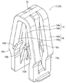
はじめに、図1〜3を参照して、実施例1に係るクリップ1とセンタークラスタ2とを個別に説明する。まず、クリップ1から説明する。クリップ1は、主として、湾曲して形成された頭部12と、この頭部12から連続する挟持部14と、この頭部12から連続する係合部16とから剛性を有する合成樹脂によって一体的に構成されている。
First, the
頭部12は、インストルメントパネル3の取付孔30に対してクリップ本体10を挿入するときの先行案内部となる。そのため、この頭部12は、外周面に丸みを帯びた湾曲形状を成している。
The
挟持部14は、センタークラスタ2のリブ24の板厚と同じか若しくは僅かに狭い間隔をもって対向する一対の挟持片14a、14aから構成されている。この一対の挟持片14a、14aは、既に説明したように、頭部12から連続する格好を成すように形成されている。
The
また、この一対の挟持片14a、14aは、自身14a、14aの間にリブ24を挿入することで、このリブ24に装着可能となっている。この挟持片14aの先端には、後述するセンタークラスタ2のリブ24の係合孔24aの上縁に係合可能な挟持爪14bが形成されている。これにより、挟持部14のリブ24に対する装着を強固にできる。
The pair of
係合部16は、一対の挟持片14a、14aの外側に弾性変形可能に形成されている一対の係合脚16a、16aから構成されている。この一対の係合脚16a、16aも、既に説明したように、頭部12から連続する格好を成すように形成されている。また、この一対の係合脚16a、16aは、クリップ本体10をインストルメントパネル3の取付孔30に挿入することで互いの間隔が狭まる方向に弾性変形可能に形成されている。
The engaging
この係合脚16aの先端側の外面には、後述するインストルメントパネル3の取付孔30の上縁に係合可能な係合斜面16cが形成されている。また、この係合脚16aの内面には、挟持片14aを境に隣り合うように対を成す弾発体16d、16dが形成されている。
On the outer surface on the distal end side of the
この弾発体16dは、係合部16(一対の係合脚16a、16a)がインストルメントパネル3の取付孔30を通過するとき、その先端がリブ24の表面に接触するように、上斜めを向いた羽状に形成されている。このときのリブ24の表面における弾発体16dの接触部位は、係合孔24aより先端側(上側)の表面24bとなっている。クリップ1は、このように構成されている。
The
次に、センタークラスタ2を説明する。センタークラスタ2は、インストルメントパネル3を覆うように取り付けられる意匠パネルである。このセンタークラスタ2は、その意匠面を有するセンタークラスタ本体20と、このセンタークラスタ本体20の内面(反意匠面)に形成されたクリップ取付座22とから剛性を有する合成樹脂によって一体的に構成されている。
Next, the
このクリップ取付座22は、係合孔24aを有するリブ24と、このリブ24へのクリップ本体10の挟持部14の装着を案内する一対のガイド26、26とから構成されている。このリブ24の係合孔24aは、既に説明したように、その上縁に一対の挟持片14a、14aの両挟持爪14bを係合可能に形成されている。また、このリブ24の係合孔24aは、従来技術のそれとは異なり、センタークラスタ本体20に対して連通するように形成されている(図1参照)。
The
そのため、このセンタークラスタ2が射出成形によって成形されていても、従来技術とは異なり、一対の挟持爪14b、14bを係合させる係合孔24aをリブ24に形成するためのスライド型を射出成形の金型とは別に必要としない。また、リブ24の先端面は、このリブ24を一対の挟持片14a、14aの間に円滑に挿入できるように、傾斜面となっている。一方、このガイド26は、張出縁26aを有する略凸字を成すように形成されている。センタークラスタ2は、このように構成されている。
Therefore, even if the
続いて、上述したクリップ1を用いて、インストルメントパネル3にセンタークラスタ2を取り付ける手順を説明する。まず、クリップ本体10の一対の挟持片14a、14aの間にセンタークラスタ2のクリップ取付座22のリブ24を相対的に挟み込む。すると、この一対の挟持片14a、14aによってリブ24が両側から挟み込まれた状態となり、これと同時に、両挟持爪14bがリブ24の係合孔24aの上縁に係合する。これにより、クリップ本体10がリブ24に装着される。
Then, the procedure which attaches the
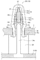
次に、リブ24に装着されたクリップ本体10を、その頭部12の側からインストルメントパネル3の取付孔30に挿入していく。すると、一対の係合脚16a、16aは、互い16a、16aが弾性によって近づく方向に撓みながら取付孔30を通過していく。やがて、クリップ取付座22の張出縁26aがインストルメントパネル3の表面に接触すると、一対の係合脚16a、16aの両係合斜面16cはインストルメントパネル3の裏面に位置することとなる(図4参照)。
Next, the clip
このとき、一対の係合脚16a、16aは、互い16a、16aが内方へ向けて弾性変形しているため、この撓みの反力によって一対の係合脚16a、16aの両係合斜面16cはインストルメントパネル3の取付孔30の上縁に押し付けられている。これにより、クリップ本体10はインストルメントパネル3に取り付けられた状態で保持され、結果として、センタークラスタ2がインストルメントパネル3に取り付けられる。
At this time, since the pair of
なお、この取り付け状態では、図4からも明らかなように、各弾発体16dはリブ24に接触していない。そのため、この取り付け状態が長時間経過しても、これら各弾発体16dには熱クリープ現象が生じることがない。ただし、一対の係合脚16a、16aには熱クリープ現象が生じることとなる。
In this attached state, as is apparent from FIG. 4, each
最後に、この取り付け状態が長時間経過したときのクリップ1の作用を説明する。このように長時間経過すると、従来技術と同様に、一対の係合脚16a、16aには熱クリープ現象が生じることとなっているため、この一対の係合脚16a、16aの弾性力が失われてインストルメントパネル3に対する保持力が低下する。
Finally, the action of the
このとき、このクリップ本体10に対して抜去荷重が作用すると、従来技術と同様に、各弾発体16dからリブ24の表面のうちの先端側の表面24b(係合孔24aより上側の表面)に作用する反力が新たな保持力として発揮されることとなる。したがって、従来技術と同様に、熱クリープ現象によってインストルメントパネル3に対する保持力が低下しているときでも、クリップ本体10に対して抜去荷重が作用したときには、インストルメントパネル3に対するクリップ本体10の取り付け状態を維持できる。
At this time, when an extraction load is applied to the
(実施例2)
次に、本発明の実施例1を、図6〜8を用いて説明する。この実施例2のクリップ101は、既に説明した実施例1のクリップ1と比較すると、弾発体16dが、より多く形成された形態である。なお、以下の説明にあたって、実施例1と同一または均等な構成の部材には、図面において同一符号を付すことで重複する説明は省略することとする。このことは、後述する実施例3においても同様である。
(Example 2)
Next, Example 1 of the present invention will be described with reference to FIGS. The
図6〜8に示すように、係合脚16aの内面には、挟持片14a(図6〜7において、図示しない)を境に隣り合うように対を成すだけでなく、上下方向にも隣り合うように弾発体16d、16d、16d、16dが形成されている。このように形成されていると、弾発体16dが4個から8個に増加するため、各弾発体16dからリブ24の表面のうちの先端側の表面24bに作用する反力が新たな保持力として発揮されるとき、この反力を高めることができる(図8参照)。したがって、この新たな保持力も高めることができるため、インストルメントパネル3に対するクリップ本体10の取り付け状態を確実に維持できる。
As shown in FIGS. 6 to 8, the inner surface of the
(実施例3)
次に、本発明の実施例3を、図9〜11を用いて説明する。この実施例3のクリップ201は、既に説明した実施例1のクリップ1と比較すると、弾発体16dが、弓状に形成された形態である。このように形成されていると、弾発体16dの弾性力を高めることができるため、各弾発体16dからリブ24の表面のうちの先端側の表面24bに作用する反力が新たな保持力として発揮されるとき、この反力を高めることができる(図11参照)。したがって、この新たな保持力も高めることができるため、インストルメントパネル3に対するクリップ本体10の取り付け状態を確実に維持できる。
(Example 3)
Next, a third embodiment of the present invention will be described with reference to FIGS. Compared with the
(変形例1)
なお、実施例1のクリップ1において、各弾発体16dが下斜めを向いた羽状に形成されていても構わない。すなわち、図12に示すクリップ301のように形成されていても構わない。
(Modification 1)
In the
(変形例2)
なお、実施例2のクリップ101において、各弾発体16dが下斜めを向いた羽状に形成されていても構わない。すなわち、図13に示すクリップ401のように形成されていても構わない。
(Modification 2)
In the
上述した内容は、あくまでも本発明の一実施の形態に関するものであって、本発明が上記内容に限定されることを意味するものではない。
各実施例では、『被取付部材』の例として、『自動車のセンタークラスタ2』を説明した。また、『相手パネル』の例として、『自動車のインストルメントパネル3』を説明した。しかし、これに限定されるものでなく、『被取付部材』が『各種の内装部材』であっても構わない。また、『相手パネル』が『各種のパネル部材』であっても構わない。
The contents described above are only related to one embodiment of the present invention, and do not mean that the present invention is limited to the above contents.
In each embodiment, “
1 クリップ(実施例1)
2 センタークラスタ(被取付部材)
3 相手パネル(インストルメントパネル)
10 クリップ本体
14 挟持部
16 係合部
16d 弾発体
22 クリップ取付座
24 リブ
24a 係合孔
30 取付孔
101 クリップ(実施例2)
201 クリップ(実施例3)
301 クリップ(変形例1)
301 クリップ(変形例2)
1 clip (Example 1)
2 Center cluster (attached member)
3 opponent panel (instrument panel)
DESCRIPTION OF
201 clips (Example 3)
301 clips (Modification 1)
301 clips (Modification 2)
Claims (1)
クリップ本体は、頭部と、前記頭部から延出して前記リブに装着される挟持部と、前記頭部から連続して前記挟持部と並んで延出して弾性変形して前記相手パネルに係合する係合部と、を備えており、
前記係合部は、外側に向けて屈曲した略く字状の屈曲点を有しており、
前記係合部の略く字の前記屈曲点を境とする反頭部側における外面には、前記相手パネルに係合可能な係合斜面が形成され、
前記係合部の内面のうち、前記係合斜面に対向する領域には、前記係合部が前記相手パネルの前記取付孔を通過するとき、前記リブの表面に接触するように前記リブに向けて突出した弾発体が形成されており、
前記弾発体は、前記リブの表面に接触するとき、前記リブの表面のうちの前記係合孔より先端側の表面に接触するように形成されていることを特徴とするクリップ。 By inserting the clip body mounted on the rib of the clip mounting seat formed on the mounting member to the mounting hole of the mating panel, the a clip removably attaching a mounted member to the mating panel,
The clip body includes a head, a sandwiching portion extending from the head and attached to the rib, and extending from the head continuously alongside the sandwiching portion and elastically deforming to engage with the counterpart panel. An engaging portion to be joined,
The engaging portion has a substantially square-shaped bending point bent outward.
An engagement slope that can be engaged with the mating panel is formed on the outer surface of the engagement portion on the side opposite to the head at the bending point of the substantially rectangular shape,
Of the inner surface of the engaging portion in a region opposed to the engagement inclined surface when said engaging portion passes through the mounting hole of the mating panel, towards the rib so as to contact the surface of the rib Projecting projectiles are formed,
The resilient body, when in contact with the surface of the rib, a clip, characterized in that it is formed so as to contact the distal end side of the surface than the engaging hole of the rib surface.
Priority Applications (5)
| Application Number | Priority Date | Filing Date | Title |
|---|---|---|---|
| JP2013120989A JP6165508B2 (en) | 2013-06-07 | 2013-06-07 | clip |
| EP14171359.4A EP2813397A1 (en) | 2013-06-07 | 2014-06-05 | Clip |
| US14/297,173 US9630572B2 (en) | 2013-06-07 | 2014-06-05 | Clip |
| IN1498DE2014 IN2014DE01498A (en) | 2013-06-07 | 2014-06-05 | |
| CN201410250319.XA CN104235125B (en) | 2013-06-07 | 2014-06-06 | Clamp |
Applications Claiming Priority (1)
| Application Number | Priority Date | Filing Date | Title |
|---|---|---|---|
| JP2013120989A JP6165508B2 (en) | 2013-06-07 | 2013-06-07 | clip |
Publications (2)
| Publication Number | Publication Date |
|---|---|
| JP2014238139A JP2014238139A (en) | 2014-12-18 |
| JP6165508B2 true JP6165508B2 (en) | 2017-07-19 |
Family
ID=50943095
Family Applications (1)
| Application Number | Title | Priority Date | Filing Date |
|---|---|---|---|
| JP2013120989A Active JP6165508B2 (en) | 2013-06-07 | 2013-06-07 | clip |
Country Status (5)
| Country | Link |
|---|---|
| US (1) | US9630572B2 (en) |
| EP (1) | EP2813397A1 (en) |
| JP (1) | JP6165508B2 (en) |
| CN (1) | CN104235125B (en) |
| IN (1) | IN2014DE01498A (en) |
Families Citing this family (21)
| Publication number | Priority date | Publication date | Assignee | Title |
|---|---|---|---|---|
| US10336265B2 (en) * | 2015-10-21 | 2019-07-02 | Termax Llc | Fastener clip over a carrier secured with hooks |
| JP5666400B2 (en) * | 2011-08-24 | 2015-02-12 | 大和化成工業株式会社 | clip |
| FR3011026B1 (en) * | 2013-09-24 | 2016-04-15 | A Raymond Et Cie | DEVICE FOR FIXING A FLAT OBJECT ON A SUPPORT PLATE AND ASSEMBLY OBTAINED |
| DE102015108347A1 (en) * | 2015-05-27 | 2016-12-01 | Illinois Tool Works Inc. | System for fastening at least one component to a carrier component of a motor vehicle |
| US9914408B2 (en) * | 2015-10-21 | 2018-03-13 | Termax Llc | Fastener clip over a carrier secured with barbs |
| CN105605047A (en) * | 2016-03-07 | 2016-05-25 | 上海球明标准件有限公司 | Metal fixing clamp for fastening mounting members |
| JP6409044B2 (en) * | 2016-12-28 | 2018-10-17 | 株式会社ニフコ | Member mounting structure and mounting clip |
| CN110234891A (en) * | 2017-02-08 | 2019-09-13 | 伊利诺斯工具制品有限公司 | Ribbed clamp assembly |
| JP6946109B2 (en) * | 2017-08-09 | 2021-10-06 | 大和化成工業株式会社 | clip |
| US11519222B1 (en) * | 2017-11-08 | 2022-12-06 | Christopher Lee Hubschmitt | Screen retention device and method of use |
| JP6917298B2 (en) * | 2017-12-27 | 2021-08-11 | 大和化成工業株式会社 | clip |
| CN109353291A (en) * | 2018-08-17 | 2019-02-19 | 蔚来汽车有限公司 | Wheel arch mounting assembly and vehicle for vehicle |
| DE102018124406A1 (en) | 2018-10-02 | 2020-04-02 | Böllhoff Verbindungstechnik GmbH | Plug-in coupling with tolerance compensation |
| CN213144979U (en) * | 2019-02-12 | 2021-05-07 | 特迈驰有限责任公司 | Fastening clip system and fastening assembly |
| EP3779215A1 (en) * | 2019-08-16 | 2021-02-17 | Termax LLC | Arrowhead fastener clip with barbs |
| US11149774B2 (en) | 2019-10-03 | 2021-10-19 | Newfrey Llc | Bathtub fastener assembly |
| US10968931B1 (en) | 2019-10-17 | 2021-04-06 | Newfrey Llc | Dual component sealing fastener and coupling assembly including same |
| CN110671396A (en) * | 2019-10-30 | 2020-01-10 | 东风安道拓汽车座椅有限公司 | Modular-design replaceable plastic part fixing structure |
| EP3907410B1 (en) * | 2020-05-07 | 2024-09-18 | Illinois Tool Works Inc. | Spring clip |
| US12024098B2 (en) * | 2020-11-16 | 2024-07-02 | Wen Chen | Windshield trim panel clips |
| US11746812B2 (en) | 2021-05-12 | 2023-09-05 | Newfrey Llc | Dual component sealing fastener and coupling assembly including same |
Family Cites Families (13)
| Publication number | Priority date | Publication date | Assignee | Title |
|---|---|---|---|---|
| DE4428142A1 (en) * | 1994-08-09 | 1996-02-22 | Pauli & Sohn Gmbh | V=Shaped clamp for plates esp. glass plates |
| JP2001074008A (en) * | 1999-09-03 | 2001-03-23 | Daiwa Kasei Ind Co Ltd | Clip mounting structure |
| JP4372306B2 (en) * | 2000-03-24 | 2009-11-25 | 大和化成工業株式会社 | clip |
| JP4375877B2 (en) * | 2000-04-05 | 2009-12-02 | 株式会社ニフコ | clip |
| JP4227741B2 (en) * | 2001-10-29 | 2009-02-18 | 株式会社ニフコ | clip |
| US7300089B2 (en) * | 2003-10-06 | 2007-11-27 | Piolax Inc. | Fixing member and a fixing structure for vehicle part |
| JP4190409B2 (en) * | 2003-12-26 | 2008-12-03 | 株式会社パイオラックス | clip |
| US20060079316A1 (en) * | 2004-09-24 | 2006-04-13 | Wms Gaming Inc. | Wagering game with an array of player-selectable elements that are preserved for subsequent gaming sessions |
| KR20070106148A (en) * | 2006-04-28 | 2007-11-01 | 한국Trw자동차부품산업 주식회사 | Fastener for mounting a trim |
| JP2008164085A (en) * | 2006-12-28 | 2008-07-17 | Daiwa Kasei Ind Co Ltd | Clip |
| JP4540726B2 (en) * | 2008-07-04 | 2010-09-08 | 大和化成工業株式会社 | Two-part assembly structure |
| WO2010104653A1 (en) * | 2009-03-13 | 2010-09-16 | Illinois Tool Works Inc. | Piercing rib clip |
| JP5666400B2 (en) * | 2011-08-24 | 2015-02-12 | 大和化成工業株式会社 | clip |
-
2013
- 2013-06-07 JP JP2013120989A patent/JP6165508B2/en active Active
-
2014
- 2014-06-05 IN IN1498DE2014 patent/IN2014DE01498A/en unknown
- 2014-06-05 US US14/297,173 patent/US9630572B2/en active Active
- 2014-06-05 EP EP14171359.4A patent/EP2813397A1/en not_active Withdrawn
- 2014-06-06 CN CN201410250319.XA patent/CN104235125B/en active Active
Also Published As
| Publication number | Publication date |
|---|---|
| US9630572B2 (en) | 2017-04-25 |
| US20140363224A1 (en) | 2014-12-11 |
| IN2014DE01498A (en) | 2015-06-19 |
| CN104235125A (en) | 2014-12-24 |
| JP2014238139A (en) | 2014-12-18 |
| EP2813397A1 (en) | 2014-12-17 |
| CN104235125B (en) | 2018-01-16 |
Similar Documents
| Publication | Publication Date | Title |
|---|---|---|
| JP6165508B2 (en) | clip | |
| JP6917298B2 (en) | clip | |
| US9103363B2 (en) | Two-piece clip assembly | |
| US20090064467A1 (en) | Clip retainer | |
| JP6255033B2 (en) | Stop | |
| US20090191025A1 (en) | Fastener | |
| EP3127751A1 (en) | Layered composite component | |
| JP2011121575A (en) | Closing plug for automobile | |
| US20140291940A1 (en) | Gasket | |
| WO2014088043A1 (en) | Hole plug | |
| JP5307936B2 (en) | Mounting member mounting structure | |
| JP5911023B2 (en) | Resin member mounting structure | |
| JP6285681B2 (en) | Locking tool to mounting hole | |
| JP5845468B2 (en) | Terminal equipment | |
| KR101629189B1 (en) | Automobile brake pads support clip | |
| JP2022015002A5 (en) | ||
| JP5840484B2 (en) | clip | |
| JP2010007808A (en) | Clip | |
| JP7081978B2 (en) | Protector and protector mounting structure | |
| JP2018044669A (en) | clip | |
| JP5331647B2 (en) | clip | |
| WO2013190721A1 (en) | Grommet and wire harness with grommet | |
| JP2015218768A (en) | Fixture | |
| JP6062307B2 (en) | Parts matching part structure | |
| JP6074638B2 (en) | fastener |
Legal Events
| Date | Code | Title | Description |
|---|---|---|---|
| A621 | Written request for application examination |
Free format text: JAPANESE INTERMEDIATE CODE: A621 Effective date: 20160401 |
|
| A977 | Report on retrieval |
Free format text: JAPANESE INTERMEDIATE CODE: A971007 Effective date: 20170119 |
|
| A131 | Notification of reasons for refusal |
Free format text: JAPANESE INTERMEDIATE CODE: A131 Effective date: 20170124 |
|
| A601 | Written request for extension of time |
Free format text: JAPANESE INTERMEDIATE CODE: A601 Effective date: 20170323 |
|
| A521 | Request for written amendment filed |
Free format text: JAPANESE INTERMEDIATE CODE: A523 Effective date: 20170517 |
|
| TRDD | Decision of grant or rejection written | ||
| A01 | Written decision to grant a patent or to grant a registration (utility model) |
Free format text: JAPANESE INTERMEDIATE CODE: A01 Effective date: 20170613 |
|
| A61 | First payment of annual fees (during grant procedure) |
Free format text: JAPANESE INTERMEDIATE CODE: A61 Effective date: 20170621 |
|
| R150 | Certificate of patent or registration of utility model |
Ref document number: 6165508 Country of ref document: JP Free format text: JAPANESE INTERMEDIATE CODE: R150 |
|
| R250 | Receipt of annual fees |
Free format text: JAPANESE INTERMEDIATE CODE: R250 |
|
| R250 | Receipt of annual fees |
Free format text: JAPANESE INTERMEDIATE CODE: R250 |
|
| R250 | Receipt of annual fees |
Free format text: JAPANESE INTERMEDIATE CODE: R250 |
|
| R250 | Receipt of annual fees |
Free format text: JAPANESE INTERMEDIATE CODE: R250 |
|
| R250 | Receipt of annual fees |
Free format text: JAPANESE INTERMEDIATE CODE: R250 |