JP6164940B2 - Lens barrel and imaging device - Google Patents

Lens barrel and imaging device Download PDF

Info

Publication number
JP6164940B2
JP6164940B2 JP2013118801A JP2013118801A JP6164940B2 JP 6164940 B2 JP6164940 B2 JP 6164940B2 JP 2013118801 A JP2013118801 A JP 2013118801A JP 2013118801 A JP2013118801 A JP 2013118801A JP 6164940 B2 JP6164940 B2 JP 6164940B2
Authority
JP
Japan
Prior art keywords
cam ring
lens barrel
optical axis
state
rotating member
Prior art date
Legal status (The legal status is an assumption and is not a legal conclusion. Google has not performed a legal analysis and makes no representation as to the accuracy of the status listed.)
Expired - Fee Related
Application number
JP2013118801A
Other languages
Japanese (ja)
Other versions
JP2014235404A (en
JP2014235404A5 (en
Inventor
光洋 泉
光洋 泉
Current Assignee (The listed assignees may be inaccurate. Google has not performed a legal analysis and makes no representation or warranty as to the accuracy of the list.)
Canon Inc
Original Assignee
Canon Inc
Priority date (The priority date is an assumption and is not a legal conclusion. Google has not performed a legal analysis and makes no representation as to the accuracy of the date listed.)
Filing date
Publication date
Application filed by Canon Inc filed Critical Canon Inc
Priority to JP2013118801A priority Critical patent/JP6164940B2/en
Publication of JP2014235404A publication Critical patent/JP2014235404A/en
Publication of JP2014235404A5 publication Critical patent/JP2014235404A5/ja
Application granted granted Critical
Publication of JP6164940B2 publication Critical patent/JP6164940B2/en
Expired - Fee Related legal-status Critical Current
Anticipated expiration legal-status Critical

Links

Images

Description

本発明は、デジタルカメラ等の撮像装置に用いられる沈胴構造を有するレンズ鏡筒に関する。   The present invention relates to a lens barrel having a retractable structure used for an imaging apparatus such as a digital camera.

レンズ鏡筒を、撮影時には光軸方向に長い使用状態(繰出状態)として所望の光学性能を確保し、非撮影時には全長を短くしてデジタルカメラ本体に収容される沈胴状態(繰込状態)として携帯性を高めたデジタルカメラが広く普及している。このようなデジタルカメラでは、撮影時の光学性能を確保するために、レンズ鏡筒の傾きやズレ等の姿勢精度を一定の範囲内に維持する必要がある。そこで、レンズ鏡筒が撮影可能時の繰出状態にあるときに、レンズ鏡筒を構成する所定の筒部材をばねで光軸方向に付勢することにより、レンズ鏡筒の姿勢精度を維持する技術が提案されている(特許文献1参照)。   The lens barrel is used in the optical axis direction that is long in the optical axis direction (drawing state) at the time of shooting to ensure the desired optical performance, and when not shooting, the entire length is shortened to be retracted (retracted state) that is accommodated in the digital camera body Digital cameras with improved portability are widely used. In such a digital camera, in order to ensure optical performance at the time of photographing, it is necessary to maintain posture accuracy such as tilt and displacement of the lens barrel within a certain range. Therefore, when the lens barrel is in the extended state when photographing is possible, a technique for maintaining the posture accuracy of the lens barrel by biasing a predetermined cylindrical member constituting the lens barrel in the optical axis direction with a spring. Has been proposed (see Patent Document 1).

特開2010−266582号公報JP 2010-266582 A

しかしながら、上記特許文献1に記載された技術では、レンズ鏡筒にばね力以上の外力が加わると、レンズ鏡筒を保持することができずに、レンズ鏡筒の姿勢精度が低下してしまうおそれがある。この問題を解決するために、外力に対する耐力を向上させる方法として、ばね力を高める方法が考えられる。しかし、上記特許文献1に記載された構造では、ばね力を高めると、これと同時に、レンズ等の光学部品を移動するための駆動力も高めなければならないという問題がある。   However, in the technique described in Patent Document 1, when an external force greater than the spring force is applied to the lens barrel, the lens barrel cannot be held and the posture accuracy of the lens barrel may be reduced. There is. In order to solve this problem, a method of increasing the spring force can be considered as a method of improving the resistance to external force. However, the structure described in Patent Document 1 has a problem that when the spring force is increased, the driving force for moving the optical component such as a lens must be increased at the same time.

本発明は、沈胴構造を有するレンズ鏡筒において、光学部品の駆動力を高めることなく、レンズ鏡筒の姿勢精度を確保することができる技術を提供することを目的とする。   It is an object of the present invention to provide a technique capable of ensuring the posture accuracy of a lens barrel without increasing the driving force of optical components in a lens barrel having a retractable structure.

本発明に係るレンズ鏡筒は、定筒と、前記固定筒に対して回転可能に支持されカム環と、記カム環の回転により前記固定筒に設けられた案内部に案内されて光軸方向に進退可能な直進筒とを備え、前記直進筒が前記光軸方向で進退することによって撮影可能状態と非撮影状態との間で遷移可能に構成されたレンズ鏡筒であって、片端近傍を前記カム環に回動可能に支持され、前記カム環の回転に応じて光軸とのなす角度が変化する回動部材と、前記カム環が前記回動部材を支持する部位に設けられ、前記レンズ鏡筒が前記撮影可能状態にあるときに、前記回動部材を回動させる力を与える第1付勢手段とを有し、前記撮影可能状態では、前記直進筒と前記回動部材とが第1当接部で当接すると共に前記カム環と前記回動部材とが第2当接部で当接し、前記第1当接部と前記第2当接部の間の前記光軸方向の距離よりも前記回動部材における前記第1当接部と前記第2当接部の間の距離の方が長いことを特徴とする。 A lens barrel according to the present invention, the solid and Teitsutsu rotatably and supported cam ring is guided by the guide portion provided in the fixed cylinder by rotation of the front Symbol cam ring with respect to the fixed barrel includes a rectilinear tube which can be moved in the optical axis direction, wherein the straight barrel is a lens barrel that is configured to be able to transition between the non-shooting state and the photographing state by forward and backward in the optical axis direction A rotation member that is rotatably supported by the cam ring in the vicinity of one end, and an angle formed with the optical axis according to the rotation of the cam ring ; and a portion where the cam ring supports the rotation member provided, when the lens barrel is in the photographable state, it has a first biasing means for applying a force to rotate the rotating member, in the photographable state, the said straight barrel The rotating member is in contact with the first contact portion, and the cam ring and the rotating member are in contact with each other. Contact with the contact portion, before Symbol first contact portion and the front Stories second contact portion of the first prior Symbol rotating member than the distance of the optical axis direction between the contact portion and the front Stories second The distance between the contact portions is longer.

本発明によれば、沈胴構造を有するレンズ鏡筒において、第1付勢部材により回動部材に作用する回転力を増幅させて直進筒を保持することができる。即ち、光学部品の駆動力を高めることなく、レンズ鏡筒の傾きやズレ等の姿勢精度を確保することができ、ひいては、レンズ鏡筒の光学性能を高い状態で維持することが可能となる。   According to the present invention, in the lens barrel having the retractable structure, the linear force cylinder can be held by amplifying the rotational force acting on the rotating member by the first urging member. That is, it is possible to ensure posture accuracy such as tilt and displacement of the lens barrel without increasing the driving force of the optical components, and thus it is possible to maintain the optical performance of the lens barrel in a high state.

本発明の第1実施形態に係るレンズ鏡筒の撮影可能状態(繰出状態)の構造を示す概略断面図である。It is a schematic sectional drawing which shows the structure of the imaging | photography possible state (drawing-out state) of the lens barrel which concerns on 1st Embodiment of this invention. 図1のレンズ鏡筒を被写体側から見た正面図である。It is the front view which looked at the lens barrel of FIG. 1 from the to-be-photographed object side. 図1のレンズ鏡筒における直進筒の沈胴動作を示す概略断面図である。It is a schematic sectional drawing which shows the collapsing operation | movement of the rectilinear cylinder in the lens barrel of FIG. 図3(a)に示すジョイント部の近傍拡大図と矢視A−A断面図である。It is the vicinity enlarged view and arrow AA sectional drawing of the joint part shown to Fig.3 (a). 図1のレンズ鏡筒におけるカム環の動作を説明するためにカム環と直進筒を筒内側から見た展開図である。FIG. 2 is a development view of a cam ring and a straight cylinder as viewed from the inside of the cylinder in order to explain the operation of the cam ring in the lens barrel of FIG. 1. 図1のレンズ鏡筒が撮影可能状態にあるときにロックリンクに働く力を説明する図である。It is a figure explaining the force which acts on a lock link when the lens-barrel of FIG. 図1のレンズ鏡筒を撮影可能状態から非撮影状態へ移行させる処理の流れを示すフローチャート及び非撮影状態から撮影可能状態へ移行させる処理の流れを示すフローチャートである。FIG. 2 is a flowchart showing a flow of processing for shifting the lens barrel of FIG. 1 from a shootable state to a non-shooting state, and a flowchart showing a flow of processing for shifting from a non-shooting state to a shootable state. 図1のレンズ鏡筒の撮影可能状態及び非撮影状態のそれぞれにおける像面側からの概略配置図である。FIG. 2 is a schematic arrangement view from the image plane side in each of a shootable state and a non-shooting state of the lens barrel of FIG. 1. 第2実施形態に係るレンズ鏡筒の概略断面図である。It is a schematic sectional drawing of the lens-barrel which concerns on 2nd Embodiment. 第2実施形態に係るレンズ鏡筒におけるカム環の動作を説明するためにカム環と直進筒を筒内側から見た展開図である。FIG. 6 is a development view of a cam ring and a straight cylinder as viewed from the inside of the cylinder in order to explain the operation of the cam ring in the lens barrel according to the second embodiment. 第2実施形態に係るレンズ鏡筒が撮影可能状態にあるときのロックリンク、ジョイント部および当接面の接触状態を説明する図である。It is a figure explaining the contact state of a lock link, a joint part, and a contact surface when the lens-barrel which concerns on 2nd Embodiment is in a photography possible state.

以下、本発明の実施形態について、添付図面を参照して詳細に説明する。ここでは、本発明に係るレンズ鏡筒の特徴的構成となる機構であるレンズを進退させる機構を中心に説明することとする。   Hereinafter, embodiments of the present invention will be described in detail with reference to the accompanying drawings. Here, the description will focus on a mechanism for moving the lens forward and backward, which is a mechanism that is a characteristic configuration of the lens barrel according to the present invention.

<第1実施形態>
図1は、本発明の第1実施形態に係るレンズ鏡筒10の撮影可能状態(繰出状態)の構造を示す概略断面図である。図2は、レンズ鏡筒10を被写体側から見た正面図である。
<First Embodiment>
FIG. 1 is a schematic cross-sectional view showing the structure of the lens barrel 10 according to the first embodiment of the present invention in a shootable state (drawn state). FIG. 2 is a front view of the lens barrel 10 as seen from the subject side.

図1に示すように、レンズ鏡筒10は、固定筒1、カム環2、直進筒3、レンズ枠4及びレンズ群5を備える。ここで、レンズ鏡筒10は、レンズ群5以外にも不図示のレンズ群を備える。また、図1では、レンズ群5を1枚のレンズで描いているが、レンズ群5は、実際には複数のレンズが組み合わされて構成されている。レンズ群5は、例えば、ズームレンズであり、図1(a)には、レンズ群5を被写体側へ繰り出した状態とすることで、画角が広角側に設定された状態が示されている。また、図1(b)には、レンズ群5を像面側に繰り込んだ状態とすることで、画角が望遠側に設定された状態が示されている。   As shown in FIG. 1, the lens barrel 10 includes a fixed barrel 1, a cam ring 2, a rectilinear barrel 3, a lens frame 4, and a lens group 5. Here, the lens barrel 10 includes a lens group (not shown) in addition to the lens group 5. In FIG. 1, the lens group 5 is drawn with a single lens, but the lens group 5 is actually configured by combining a plurality of lenses. The lens group 5 is, for example, a zoom lens. FIG. 1A shows a state in which the angle of view is set to the wide angle side by setting the lens group 5 to the subject side. . FIG. 1B shows a state in which the field angle is set to the telephoto side by setting the lens group 5 to the image plane side.

固定筒1は、不図示のカメラ本体に固定される。カム環2は、略円筒形状を有しており、光軸を回転中心として回転可能な状態で固定筒1に支持(係合)されている。カム環2は、不図示のモータ等により駆動力を受けることで回転する。直進筒3は、略円筒形状を有しており、カム環2の回転に伴って光軸方向に進退可能な状態でカム環2に係合されている。なお、直進筒3の進退に関しては後述する。   The fixed cylinder 1 is fixed to a camera body (not shown). The cam ring 2 has a substantially cylindrical shape, and is supported (engaged) by the fixed cylinder 1 in a state where the cam ring 2 can rotate about the optical axis. The cam ring 2 rotates by receiving a driving force from a motor or the like (not shown). The rectilinear cylinder 3 has a substantially cylindrical shape, and is engaged with the cam ring 2 in a state where it can advance and retreat in the optical axis direction as the cam ring 2 rotates. The advance and retreat of the straight cylinder 3 will be described later.

直進筒3には、レンズ枠4を光軸方向で案内するための第1メインバー6aとサブバー6cを有する。第1メインバー6aとサブバー6cはそれぞれ、光軸と平行な方向に延出し、各両端は直進筒3に保持されている。固定筒1は、直進筒3を光軸方向で案内するための第2メインバー6bを有する。第2メインバー6bは、円柱形状を有し、光軸と平行な方向に延出し、後述の嵌合穴部9bと嵌合する。第2メインバー6bの両端は固定筒1に保持されている。なお、第2メインバー6b、第1メインバー6a及びサブバー6cはそれぞれ、ステンレス等で構成することができる。   The rectilinear cylinder 3 has a first main bar 6a and a sub bar 6c for guiding the lens frame 4 in the optical axis direction. Each of the first main bar 6a and the sub bar 6c extends in a direction parallel to the optical axis, and both ends thereof are held by the rectilinear cylinder 3. The fixed cylinder 1 has a second main bar 6b for guiding the rectilinear cylinder 3 in the optical axis direction. The second main bar 6b has a cylindrical shape, extends in a direction parallel to the optical axis, and engages with a fitting hole 9b described later. Both ends of the second main bar 6 b are held by the fixed cylinder 1. The second main bar 6b, the first main bar 6a, and the sub bar 6c can each be made of stainless steel or the like.

レンズ群5を保持するレンズ枠4は、レンズ群5の光軸方向における位置を調整することで、光線(被写体からの反射光)の結像状態を変えることができる。レンズ枠4は、略円筒穴形状の嵌合穴部9a,9bを有し、嵌合穴部9aには第1メインバー6aが摺動自在に挿通されており、嵌合穴部9bには第2メインバー6bが摺動自在に挿通されている。ここで、嵌合穴部9a,9bはそれぞれ、第1メインバー6a,第2メインバー6bに対して若干のガタを有しており、そのため、レンズ枠4は光軸に対してこのガタの分だけ倒れが発生し得る。但し、嵌合穴部9a,9bは距離Lだけ離れて設けられているため、距離Lが長くなると、レンズ枠4は光軸に対して倒れ難くなる。   The lens frame 4 that holds the lens group 5 can change the imaging state of light rays (reflected light from the subject) by adjusting the position of the lens group 5 in the optical axis direction. The lens frame 4 has substantially cylindrical hole-shaped fitting holes 9a and 9b, and the first main bar 6a is slidably inserted in the fitting hole 9a. The second main bar 6b is slidably inserted. Here, the fitting hole portions 9a and 9b have some backlash with respect to the first main bar 6a and the second main bar 6b, respectively. Therefore, the lens frame 4 has the backlash with respect to the optical axis. There can be a fall. However, since the fitting holes 9a and 9b are provided apart by a distance L, the lens frame 4 is not easily tilted with respect to the optical axis as the distance L increases.

レンズ枠4の倒れは、第1メインバー6aと第2メインバー6bとの相対位置が変化することによっても生じ得る。そのため、レンズ枠4の倒れを低減するためには、第1メインバー6aと第2メインバー6bとの相対位置が変化しないように、保持することが重要である。そこで、レンズ枠4には、サブバー6cが挿通される嵌合穴部9cが設けられている。図2に示すように、嵌合穴部9cは正面から見たときにU字形状を有しており、サブバー6cと嵌合穴部9cとは、嵌合穴部9a,9bを結ぶ軸方向での倒れを抑制する方向に嵌合している。   The tilt of the lens frame 4 can also occur when the relative position between the first main bar 6a and the second main bar 6b changes. Therefore, in order to reduce the tilt of the lens frame 4, it is important to hold the first main bar 6a and the second main bar 6b so that the relative positions of the first main bar 6a and the second main bar 6b do not change. Therefore, the lens frame 4 is provided with a fitting hole 9c through which the sub bar 6c is inserted. As shown in FIG. 2, the fitting hole 9c has a U-shape when viewed from the front, and the sub-bar 6c and the fitting hole 9c are axially connected to the fitting holes 9a and 9b. It is fitted in the direction to suppress the falling down.

レンズ鏡筒10では、固定筒1にモータ8が固定されており、送りねじ7がモータ8の出力軸に取り付けられている。また、送りねじ7と螺合するラック41がレンズ枠4に取り付けられている。よって、モータ8を駆動して送りねじ7を回転させることにより、ラック41の位置を光軸方向において移動させることができ、ラック41の位置の移動に伴ってレンズ枠4の光軸方向での位置が移動する。つまり、モータ8の駆動によって、レンズ群5を光軸方向の所望の位置へ移動させることができる。   In the lens barrel 10, a motor 8 is fixed to the fixed cylinder 1, and a feed screw 7 is attached to the output shaft of the motor 8. A rack 41 that is screwed with the feed screw 7 is attached to the lens frame 4. Therefore, by driving the motor 8 and rotating the feed screw 7, the position of the rack 41 can be moved in the optical axis direction, and the movement of the position of the rack 41 in the optical axis direction of the lens frame 4 can be performed. The position moves. That is, the lens group 5 can be moved to a desired position in the optical axis direction by driving the motor 8.

なお、モータ8としてステッピングモータを用いた場合、駆動に用いられるパルス数をカウントすることにより、レンズ枠4の移動量を正確に、且つ、簡単に把握することができる。また、図1に示すようにレンズ枠4に遮光壁45を設け、固定筒1に位置検出センサ15を設けることにより、固定筒1に対するレンズ枠4の絶対位置を把握することができる。   When a stepping motor is used as the motor 8, the movement amount of the lens frame 4 can be accurately and easily grasped by counting the number of pulses used for driving. Further, as shown in FIG. 1, by providing a light shielding wall 45 on the lens frame 4 and a position detection sensor 15 on the fixed cylinder 1, the absolute position of the lens frame 4 with respect to the fixed cylinder 1 can be grasped.

図3は、レンズ鏡筒10における直進筒3の沈胴動作を示す概略断面図であり、図3(a)は撮影可能状態(操出状態)を示しており、図3(b)は非撮影状態(沈胴状態(繰込状態))を示している。固定筒1は、カム環2が光軸方向で抜けてしまうことを防止するためのバヨネット部16を有する。固定筒1におけるバヨネット部16近傍のカム環2が入り込む空間には、金属板を湾曲させて構成されたスラストばね17(第3付勢手段)が配置されている。スラストばね17は、カム環2を光軸方向の像面側に押し付ける。これにより、カム環2は、固定筒1に対して光軸方向において位置決めされる。また、スラストばね17により、固定筒1とカム環2との、光軸に直交する当接面13に付勢力が発生し、摩擦力へ変換される。この摩擦力により、カム環2が外力により回転してしまうことが抑制される。   FIG. 3 is a schematic cross-sectional view showing the retracting operation of the rectilinear barrel 3 in the lens barrel 10, FIG. 3 (a) shows a photographing enabled state (operating state), and FIG. The state (collapsed state (retracted state)) is shown. The fixed cylinder 1 has a bayonet portion 16 for preventing the cam ring 2 from coming off in the optical axis direction. In the space where the cam ring 2 near the bayonet portion 16 in the fixed cylinder 1 enters, a thrust spring 17 (third urging means) configured by bending a metal plate is disposed. The thrust spring 17 presses the cam ring 2 against the image plane side in the optical axis direction. Thereby, the cam ring 2 is positioned with respect to the fixed cylinder 1 in the optical axis direction. Further, the thrust spring 17 generates a biasing force on the contact surface 13 of the fixed cylinder 1 and the cam ring 2 that is orthogonal to the optical axis, and is converted into a frictional force. This frictional force prevents the cam ring 2 from rotating due to an external force.

直進筒3には直進キー32が設けられており、直進キー32が固定筒1に設けられた案内部としての直進ガイド11と係合することで、直進筒3は固定筒1に対して光軸方向に進退可能となっている。また、直進筒3にはカムフォロア31が設けられており、カムフォロア31がカム環2に設けられたカム溝21と係合することで、カム環2の回転位置に対する直進筒3の光軸方向の位置が決定される。カム環2を回転させてカムフォロア31の光軸方向位置を被写体側へ進めると、直進筒3が最も被写体側へ近寄った図3(a)の撮影可能状態となる。また、カム環2を回転させてカムフォロア31の光軸方向位置を像面側に後退させると、直進筒3が最も像面側へ近寄った図3(b)の非撮影状態となる。   The rectilinear cylinder 3 is provided with a rectilinear key 32, and the rectilinear key 3 engages with the rectilinear guide 11 as a guide portion provided in the fixed cylinder 1, so that the rectilinear cylinder 3 is optically coupled to the fixed cylinder 1. It can be moved forward and backward in the axial direction. Further, the straight cylinder 3 is provided with a cam follower 31, and the cam follower 31 is engaged with the cam groove 21 provided in the cam ring 2, so that the linear cylinder 3 is rotated in the optical axis direction with respect to the rotational position of the cam ring 2. The position is determined. When the cam ring 2 is rotated and the position of the cam follower 31 in the optical axis direction is advanced to the subject side, the straight-ahead cylinder 3 is closest to the subject side and the photographing possible state shown in FIG. Further, when the cam ring 2 is rotated and the position of the cam follower 31 in the optical axis direction is retracted to the image plane side, the non-photographing state shown in FIG.

直進ガイド11の被写体側の端部には、光軸と直交し、直進筒3と当接する当接面12が設けられている。直進筒3が最も被写体側に繰り出した状態(図3(a))において、直進筒3は当接面12に当接することで、固定筒1に対して保持された状態となる。レンズ鏡筒10は、略棒形状のロックリンク27を有している。ロックリンク27は、片端近傍を中心として回動可能に支持される回動部材である。図3(a)の撮影可能状態では、ロックリンク27は、直進筒3の像面側の端面である当接面33を介して直進筒3を被写体側へ押圧することで、直進筒3を固定し、保持する。なお、ロックリンク27の詳細については後述するが、カム環2には球状の先端部を有するジョイント部22が設けられており、ロックリンク27の片端がジョイント部22に回転自在に取り付けられている。   At the end of the rectilinear guide 11 on the subject side, a contact surface 12 that is orthogonal to the optical axis and abuts the rectilinear cylinder 3 is provided. In a state where the rectilinear cylinder 3 is extended to the most object side (FIG. 3A), the rectilinear cylinder 3 comes into contact with the abutment surface 12 and is held with respect to the fixed cylinder 1. The lens barrel 10 has a substantially rod-shaped lock link 27. The lock link 27 is a rotating member that is supported so as to be rotatable around one end. 3A, the lock link 27 presses the rectilinear cylinder 3 toward the subject via the contact surface 33 that is an end surface on the image plane side of the rectilinear cylinder 3, thereby causing the rectilinear cylinder 3 to move. Secure and hold. Although details of the lock link 27 will be described later, the cam ring 2 is provided with a joint portion 22 having a spherical tip, and one end of the lock link 27 is rotatably attached to the joint portion 22. .

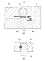
図4(a)は、図3(a)のジョイント部22の近傍拡大図であり、図4(b)は、図4(a)中に示す矢視A−A断面図である。ロックリンク27は、ジョイント部22に嵌合しており、ロックリンク27の回動中心となる側の先端部とカム環2との間には、ロックリンク27をカム環2の径方向に付勢するばね27aが配置されている。ばね27aは、ロックリンク27の回動中心を支点として、ロックリンク27の回動中心から遠い方の端部を常にカム環2の内側円筒面に沿わせる。このような状態が維持できる限りにおいて、ばね27aの付勢力は弱くても構わない。   4A is an enlarged view of the vicinity of the joint portion 22 in FIG. 3A, and FIG. 4B is a cross-sectional view taken along the line AA in FIG. 4A. The lock link 27 is fitted to the joint portion 22, and the lock link 27 is attached in the radial direction of the cam ring 2 between the cam ring 2 and the tip end on the side of the rotation center of the lock link 27. An energizing spring 27a is arranged. The spring 27a always places the end portion far from the rotation center of the lock link 27 along the inner cylindrical surface of the cam ring 2 with the rotation center of the lock link 27 as a fulcrum. As long as such a state can be maintained, the biasing force of the spring 27a may be weak.

ジョイント部22の軸にはトーションばね27b(第2付勢手段)が巻き付けられており、トーションばね27bは、ロックリンク27とカム環2との間にロックリンク27を回動方向に付勢する力を発生させ、ロックリンク27を常に光軸と平行な方向に押し付ける。トーションばね27bの付勢力は、ロックリンク27を押し付けることが目的であるため、微弱であっても構わない。   A torsion spring 27 b (second urging means) is wound around the shaft of the joint portion 22, and the torsion spring 27 b urges the lock link 27 between the lock link 27 and the cam ring 2 in the rotational direction. A force is generated, and the lock link 27 is always pressed in a direction parallel to the optical axis. Since the urging force of the torsion spring 27b is for the purpose of pressing the lock link 27, it may be weak.

図4(b)に示すように、ジョイント部22の球状部には一部に切り欠き部が形成されており、この切り欠き部にロック保持ばね27c(第1付勢手段)が配置されている。非撮影状態では、ロック保持ばね27cは殆ど力を発生していない。撮影可能状態では、ジョイント部22とロックリンク27との間が押し付けられることで、ロック保持ばね27cは、ロックリンク27とジョイント部22の間で付勢力を発生する。   As shown in FIG. 4B, a cutout portion is formed in a part of the spherical portion of the joint portion 22, and a lock holding spring 27c (first urging means) is arranged in the cutout portion. Yes. In the non-photographing state, the lock holding spring 27c generates almost no force. In the photographing enabled state, the lock holding spring 27 c generates an urging force between the lock link 27 and the joint portion 22 by being pressed between the joint portion 22 and the lock link 27.

次に、直進筒3の沈胴動作について、図3、図5及び図6を参照して説明する。図5は、カム環2の動作を説明するためにカム環2と直進筒3を筒内側から見た展開図である。カム環2は回転すると紙面の上下方向に移動し、直進筒3が光軸方向に進退すると紙面の左右方向に移動するものとする。図5(a)は、撮影可能状態を示しており、図3(a)の断面図に相当する。図5(b)は、直進筒3が固定保持されない状態での繰り出し途中の状態を示している。図5(c)は、非撮影状態を示しており、図3(b)の断面図に相当する。   Next, the retracting operation of the rectilinear cylinder 3 will be described with reference to FIGS. 3, 5, and 6. FIG. FIG. 5 is a developed view of the cam ring 2 and the rectilinear cylinder 3 as viewed from the inside of the cylinder in order to explain the operation of the cam ring 2. The cam ring 2 moves in the vertical direction on the paper surface when rotated, and moves in the left-right direction on the paper surface when the rectilinear cylinder 3 advances and retracts in the optical axis direction. FIG. 5A shows a photographable state and corresponds to the cross-sectional view of FIG. FIG. 5B shows a state in which the rectilinear cylinder 3 is being fed out in a state where it is not fixedly held. FIG. 5C shows a non-photographing state and corresponds to the cross-sectional view of FIG.

先ず、撮影可能状態での各部の機能と作用について説明する。図5(a)において、カム環2は所定の回転位置で静止している。カム環2はスラストばね17により光軸方向の像面側に付勢されているため、固定筒1に対する当接面13において摩擦力Fuが発生し、カム環2が回転しないように保持されている。ロック保持ばね27cは、静止したカム環2のジョイント部22から紙面下方向の力Fs(図6参照)を受けて撓められ、ロックリンク27を紙面下方向へ押し付けている。一方、ロックリンク27において回動中心から遠い方の端部は、直進筒3に対して当接面33で当接している。また、ロックリンク27の回動方向は、直進筒3に設けられた回動規制壁34により回動が規制されている。さらに、直進筒3は、直進ガイド11の当接面12によって固定筒1に押し付けられている。そのため、ロックリンク27には、回動規制壁34により回動が規制された状態で、ロック保持ばね27cが発生している力Fsによって光軸と平行となるように回動しようとする力が働き、同時に、ロックリンク27は光軸方向に長さが長くなろうとする。   First, the function and operation of each part in the photographing enabled state will be described. In FIG. 5A, the cam ring 2 is stationary at a predetermined rotational position. Since the cam ring 2 is urged toward the image plane side in the optical axis direction by the thrust spring 17, a frictional force Fu is generated on the contact surface 13 with respect to the fixed cylinder 1, and the cam ring 2 is held so as not to rotate. Yes. The lock holding spring 27c is bent by receiving a downward force Fs (see FIG. 6) from the joint portion 22 of the cam ring 2, and presses the lock link 27 downward in the paper surface. On the other hand, the end of the lock link 27 that is far from the center of rotation is in contact with the rectilinear cylinder 3 at the contact surface 33. Further, the rotation direction of the lock link 27 is restricted by a turning restriction wall 34 provided on the rectilinear cylinder 3. Further, the rectilinear cylinder 3 is pressed against the fixed cylinder 1 by the contact surface 12 of the rectilinear guide 11. For this reason, the lock link 27 has a force to rotate so as to be parallel to the optical axis by the force Fs generated by the lock holding spring 27c in a state where the rotation is restricted by the rotation restriction wall 34. At the same time, the lock link 27 tends to increase in length in the optical axis direction.

図6は、レンズ鏡筒10が撮影可能状態にあるときにロックリンク27に働く力を説明する図である。当接点101は、直進筒3の当接面33とロックリンク27とが当接する点(第1当接部)である。当接点102は、ジョイント部22の外周面とロックリンク27とが当接する点(第2当接部)である。当接点103は、回動規制壁34上のロックリンク27と当接する点である。なお、これらの当接点101〜103は、点接触に限定されず、線接触或いは面接触等の接触状態でもあっても構わない。   FIG. 6 is a diagram for explaining the force acting on the lock link 27 when the lens barrel 10 is in a photographing enabled state. The contact 101 is a point (first contact portion) where the contact surface 33 of the rectilinear cylinder 3 and the lock link 27 contact. The contact 102 is a point (second contact portion) at which the outer peripheral surface of the joint portion 22 and the lock link 27 contact. The contact 103 is a point that contacts the lock link 27 on the rotation restricting wall 34. Note that these contact points 101 to 103 are not limited to point contact, and may be in a contact state such as line contact or surface contact.

当接面33上の当接点101とジョイント部22上の当接点102との光軸方向の長さをLwとし、ロックリンク27上の当接点101と当接点102との距離をLrとする。撮影可能状態において、“Lr>Lw”の関係が成り立つように設計することにより、ロックリンク27は、当接点103において回転を規制される。その結果、ロックリンク27は光軸方向と平行になるまで回動することはなく、必ず、所定の角度θという傾きを持って力がり合っていることとなる。 The length in the optical axis direction between the contact point 101 on the contact surface 33 and the contact point 102 on the joint portion 22 is Lw, and the distance between the contact point 101 on the lock link 27 and the contact point 102 is Lr. By designing so that the relationship of “Lr> Lw” is established in the photographing enabled state, the lock link 27 is restricted from rotating at the contact point 103. As a result, the lock link 27 is not able to rotate until they are parallel to the optical axis direction, always so that the matching Ri One force with an inclination of a predetermined angle theta.

ロックリンク27の回転中心近傍に作用する力Fsは、図6に丸(○)と三角(△)で記した力に分配される。ロックリンク27の回動中心から遠い側でも、同様の力の分配が行われる。つまり、丸(○)で記した力が直進筒3を押し付ける力Fr相当となる。式で表すと、“Fr=Fs/tan(θ)”という関係となる。例えばθ=5°の場合には、“Fr=11.4×Fs”となり、Frの大きさはFsの大きさの10倍以上に増幅されることになる。このようにカム環2の回転方向には小さな力を発生させることで、直進筒3を高い力で安定して保持することが可能になる。   The force Fs acting in the vicinity of the rotation center of the lock link 27 is distributed to the forces indicated by circles (◯) and triangles (Δ) in FIG. Similar force distribution is performed on the side of the lock link 27 far from the center of rotation. That is, the force indicated by a circle (◯) corresponds to the force Fr for pressing the straight cylinder 3. Expressed by the equation, the relationship is “Fr = Fs / tan (θ)”. For example, when θ = 5 °, “Fr = 11.4 × Fs”, and the magnitude of Fr is amplified to 10 times or more of the magnitude of Fs. By generating a small force in the rotational direction of the cam ring 2 in this way, it becomes possible to stably hold the rectilinear cylinder 3 with a high force.

ロック保持ばね27cによる力Fsの大きさは、その反力によりカム環2が回転しまうことを防止するために、摩擦力Fuの大きさよりも小さく設定する必要がある。一方で、カム環2を回転させるためには、力Fsと摩擦力Fuを合わせた力よりも大きな力が必要となる。ここで、力Fsを小さくした場合でも、ロックリンク27を介して力Fsは増幅されるため、直進筒3を十分大きな力で保持することが可能である。その結果として、カム環2の駆動力を大きくすることなく、直進筒3を安定して保持することが可能となる。   The magnitude of the force Fs by the lock holding spring 27c needs to be set smaller than the magnitude of the frictional force Fu in order to prevent the cam ring 2 from rotating due to the reaction force. On the other hand, in order to rotate the cam ring 2, a force larger than the combined force Fs and friction force Fu is required. Here, even when the force Fs is reduced, the force Fs is amplified via the lock link 27, so that the rectilinear cylinder 3 can be held with a sufficiently large force. As a result, it is possible to stably hold the rectilinear cylinder 3 without increasing the driving force of the cam ring 2.

次に、レンズ鏡筒10を撮影可能状態から非撮影状態へ移行させる処理について、図5及び図7(a)を参照して説明する。図7(a)は、レンズ鏡筒10を撮影可能状態から非撮影状態へ移行させる処理の流れを示すフローチャートである。図7(a)の各ステップの動作制御は、レンズ鏡筒10が取り付けられる不図示の撮像装置本体の制御部が直接に、又は、撮像装置本体の制御部からの指令を受けたレンズ鏡筒10内の制御部が、レンズ鏡筒10の各種駆動要素の動作を制御することにより行われる。   Next, a process for shifting the lens barrel 10 from the shootable state to the non-shooting state will be described with reference to FIGS. 5 and 7A. FIG. 7A is a flowchart showing a flow of processing for shifting the lens barrel 10 from the shootable state to the non-shooting state. The operation control of each step of FIG. 7A is performed by a lens barrel that is directly or directly received by a control unit of an imaging device body (not shown) to which the lens barrel 10 is attached. 10 is performed by controlling operations of various driving elements of the lens barrel 10.

ステップS701において、モータ8を駆動することによりレンズ枠4を退避させる。これは、レンズ鏡筒10が撮影可能状態から非撮影状態へ移行する際には、直進筒3との干渉を避けるために、レンズ位置を最も像面側に下げた状態にする必要があるからである。ここで、図1を参照して説明した通り、モータ8を駆動して送りねじ7を回転させることにより、レンズ枠4に取り付けられたラック41の位置を光軸方向で移動させることができ、ラック41の移動に伴ってレンズ枠4も移動する。レンズ枠4の光軸方向での可動範囲は、第2メインバー6b、第1メインバー6a及びサブバー6cにより制限されており、ステップS701により、レンズ枠4は図1(b)又は図3(a),(b)に示した位置へ移動する。   In step S701, the lens frame 4 is retracted by driving the motor 8. This is because, when the lens barrel 10 shifts from the shootable state to the non-shooting state, the lens position needs to be lowered to the most image plane side in order to avoid interference with the rectilinear tube 3. It is. Here, as described with reference to FIG. 1, the position of the rack 41 attached to the lens frame 4 can be moved in the optical axis direction by driving the motor 8 and rotating the feed screw 7. As the rack 41 moves, the lens frame 4 also moves. The movable range of the lens frame 4 in the optical axis direction is limited by the second main bar 6b, the first main bar 6a, and the sub bar 6c, and the lens frame 4 is moved to the position shown in FIG. Move to the positions shown in a) and (b).

ステップS702では、カム環2の繰込方向(直進筒3を被写体側から像面側へ移動させる方向)への回転を開始する。これにより、カム環2は、図5(a)の紙面上では上方向に移動を開始することになる。カム環2が繰込方向へ回転を始めると、ステップS703において、カム環2の回転に応じてロック保持ばね27cを付勢している力が解除される。これにより、ロックリンク27は回動方向に自由となり、ばね27aとトーションばね27bにより片寄せされながら動作する。その結果、図5(b)のように、ロックリンク27の回動中心から遠い方の先端は、直進筒3の壁面に沿って動く。しかし、このとき、まだ、直進筒3は光軸方向へ移動していない。 In step S702, the cam ring 2 starts to rotate in the feeding direction (the direction in which the rectilinear cylinder 3 is moved from the subject side to the image plane side). As a result, the cam ring 2 starts to move upward on the paper surface of FIG. When the cam ring 2 starts to rotate in the retracting direction, in step S703, the force that biases the lock holding spring 27c according to the rotation of the cam ring 2 is released. As a result, the lock link 27 becomes free in the rotating direction and operates while being biased by the spring 27a and the torsion spring 27b. As a result, as shown in FIG. 5B, the distal end of the lock link 27 far from the rotation center moves along the wall surface of the straight cylinder 3. However, at this time, the rectilinear cylinder 3 has not yet moved in the optical axis direction.

続くステップS704では、直進筒3が沈胴を開始する。つまり、図5(b)においてカム環2がさらに紙面上方に移動することで、カムフォロア31がカム溝21に沿うように光軸方向の移動を開始する。その後、ステップS705において、直進筒3の光軸方向の移動が完了する。更に、ステップS706において、カム環2の回転が停止する。こうして、レンズ鏡筒10の撮影可能状態から非撮影状態への移行が完了する。   In subsequent step S704, the rectilinear cylinder 3 starts to retract. That is, in FIG. 5B, the cam ring 2 further moves upward in the drawing, whereby the cam follower 31 starts moving in the optical axis direction along the cam groove 21. Thereafter, in step S705, the movement of the rectilinear cylinder 3 in the optical axis direction is completed. Further, in step S706, the rotation of the cam ring 2 is stopped. In this way, the transition of the lens barrel 10 from the shootable state to the non-shooting state is completed.

続いて、レンズ鏡筒10を非撮影状態から撮影可能状態へ移行させる処理について、図5及び図7(b)を参照して説明する。図7(b)は、レンズ鏡筒10を非撮影状態から撮影可能状態へ移行させる処理の流れを示すフローチャートである。   Next, a process for shifting the lens barrel 10 from the non-photographing state to the photographable state will be described with reference to FIGS. 5 and 7B. FIG. 7B is a flowchart showing a flow of processing for shifting the lens barrel 10 from the non-photographing state to the photographing enabled state.

ステップS711において、カム環2の繰出方向(直進筒3を像面側から被写体側へ移動させる方向)への回転を開始する。これにより、ステップS712において、直進筒3の繰り出しが開始され、図5(c)から図5(b)の状態になるまで直進筒3の繰り出しが継続する。そして、図5(b)の状態に至るステップS713において、直進筒3の繰り出しは完了するが、その後もカム環2の回転は継続しており、ステップS714においてロック保持ばね27cが作用する。その後、ステップS715において、ロック保持ばね27cが作用した状態で、カム環2の回転が停止する。これにより、ロック保持ばね27cによる付勢力が発生して直進筒3の保持が完了し、撮影可能状態となる。   In step S711, rotation of the cam ring 2 in the feeding direction (the direction in which the rectilinear cylinder 3 is moved from the image plane side to the subject side) is started. As a result, in step S712, the delivery of the straight cylinder 3 is started, and the linear cylinder 3 continues to be fed until the state shown in FIG. 5C is changed to the state shown in FIG. 5B. In step S713 that reaches the state of FIG. 5B, the delivery of the straight cylinder 3 is completed, but the rotation of the cam ring 2 continues thereafter, and the lock holding spring 27c acts in step S714. Thereafter, in step S715, the rotation of the cam ring 2 is stopped with the lock holding spring 27c acting. As a result, an urging force is generated by the lock holding spring 27c, the holding of the straight cylinder 3 is completed, and the photographing is enabled.

図8(a)は、レンズ鏡筒10の撮影可能状態における像面側からの概略配置図であり、図8(b)は、レンズ鏡筒10の非撮影状態における像面側からの概略配置図である。図8(a)に示すように、撮影可能状態では、ロックリンク27を光軸と直交する面内へ投影すると、ロックリンク27は、光軸方向に略平行となってカム環2の内周面に沿うように光軸から離れた位置に配置される。こうして、撮影可能状態では、ロックリンク27がレンズ鏡筒10の内径側の光路(レンズ群5と重なる位置)へ入り込むことがないため、撮影に支障は生じない。これに対して、図8(b)に示すように、非撮影状態では、ロックリンク27は、カム環2の周方向に長くなってロックリンク27の中央部が光軸に近付いて、レンズ鏡筒10の内径側の光路へ入り込んで配置される。しかし、非撮影状態では撮影が行われることはないため、ロックリンク27がレンズ鏡筒10の光路へ進入しても問題はない。   FIG. 8A is a schematic arrangement view from the image plane side when the lens barrel 10 can be photographed, and FIG. 8B is a schematic arrangement from the image plane side when the lens barrel 10 is not photographed. FIG. As shown in FIG. 8A, in the photographing enabled state, when the lock link 27 is projected into a plane orthogonal to the optical axis, the lock link 27 becomes substantially parallel to the optical axis direction and the inner periphery of the cam ring 2. It arrange | positions in the position away from the optical axis so that the surface may be followed. In this way, in the photographing enabled state, the lock link 27 does not enter the optical path on the inner diameter side of the lens barrel 10 (position overlapping the lens group 5), so that shooting is not hindered. On the other hand, as shown in FIG. 8B, in the non-photographing state, the lock link 27 becomes longer in the circumferential direction of the cam ring 2 and the central portion of the lock link 27 approaches the optical axis, so that the lens mirror It is arranged so as to enter the optical path on the inner diameter side of the cylinder 10. However, since shooting is not performed in the non-shooting state, there is no problem even if the lock link 27 enters the optical path of the lens barrel 10.

以上の説明の通り、本実施形態では、カム環2の回転力をロックリンク27により増幅した力で直進筒3を保持することができ、これにより、カム環2の駆動力を高めることなく、大きな力で直進筒3を保持することができる。その結果、外力に対して耐力を向上させ、レンズ鏡筒10の傾きやズレ等の姿勢精度を一定の精度に確保することができ、光学性能を高い状態に維持することができる。   As described above, in the present embodiment, the straight cylinder 3 can be held by the force obtained by amplifying the rotational force of the cam ring 2 by the lock link 27, thereby increasing the driving force of the cam ring 2. The straight cylinder 3 can be held with a large force. As a result, it is possible to improve the proof strength against external force, to ensure the posture accuracy such as the inclination and displacement of the lens barrel 10 with a certain accuracy, and to maintain the optical performance in a high state.

<第2実施形態>
本発明の第2実施形態について、上述の第1実施形態とは異なる部分について以下に説明する。よって、第2実施形態において第1実施形態と共通する内容についての説明は割愛することとする。
Second Embodiment
The second embodiment of the present invention will be described below with respect to parts different from the first embodiment described above. Therefore, in the second embodiment, description of contents common to the first embodiment will be omitted.

図9は、第2実施形態に係るレンズ鏡筒の概略断面図であり、図3(a)に対応する状態が示されている。図10は、第2実施形態に係るレンズ鏡筒におけるカム環2の動作を説明するためにカム環2と直進筒3を筒内側から見た展開図であり、図5に対応する状態が示されている。   FIG. 9 is a schematic cross-sectional view of a lens barrel according to the second embodiment, showing a state corresponding to FIG. FIG. 10 is a developed view of the cam ring 2 and the rectilinear cylinder 3 as viewed from the inside of the cylinder in order to explain the operation of the cam ring 2 in the lens barrel according to the second embodiment, and shows a state corresponding to FIG. Has been.

第2実施形態では、ジョイント部22は直進筒3に設置され、ロックリンク27は直進筒3に対して相対的に回動可能となるようにジョイント部22に取り付けられる。ばね27aは、直進筒3とロックリンク27の間を付勢するように設置された突っ張りばねであり、ロックリンク27の回動中心より遠い方の端部をカム環2の内側円筒面に沿わせる。ジョイント部22の軸上にはトーションばね27bが巻き付けられており、トーションばね27bは、ロックリンク27と直進筒3との間で回動付勢力を発生し、ロックリンク27を常に光軸と平行な方向に押し付けている。   In the second embodiment, the joint part 22 is installed in the rectilinear cylinder 3, and the lock link 27 is attached to the joint part 22 so as to be rotatable relative to the rectilinear cylinder 3. The spring 27 a is a tension spring that is installed so as to urge between the rectilinear cylinder 3 and the lock link 27, and the end of the lock link 27 that is farther from the rotation center extends along the inner cylindrical surface of the cam ring 2. Make it. A torsion spring 27b is wound around the shaft of the joint portion 22, and the torsion spring 27b generates a rotational biasing force between the lock link 27 and the straight cylinder 3 so that the lock link 27 is always parallel to the optical axis. It is pushing in the right direction.

カム環2の回動規制壁34にはロック保持ばね27cが設置されており、ロック保持ばね27cは、カム環2の回転に伴ってカム環2と一体的に移動する。撮影可能状態では、ロック保持ばね27cは、ロックリンク27と接触して力Fsを発生する。その結果、ロックリンク27には、ジョイント部22とカム環2が有する当接面33とに挟まれた領域内でさらに回動しようとする回転力が発生し、直進筒3を力Frで保持することができる。第2実施形態では、ロックリンク27は、直進筒3に設置されているためにカム溝21と同時に回転せず、よって、カム溝21との位置関係において設計・配置の自由度が高められる。 A lock holding spring 27 c is installed on the rotation restriction wall 34 of the cam ring 2, and the lock holding spring 27 c moves integrally with the cam ring 2 as the cam ring 2 rotates. In the photographing enabled state, the lock holding spring 27c contacts the lock link 27 and generates a force Fs. As a result, a rotational force is generated in the lock link 27 so as to further rotate within a region sandwiched between the joint portion 22 and the contact surface 33 of the cam ring 2, and the straight cylinder 3 is held with the force Fr. can do. In the second embodiment, since the lock link 27 is installed in the rectilinear cylinder 3, it does not rotate simultaneously with the cam groove 21, and thus the degree of freedom in design and arrangement is enhanced in the positional relationship with the cam groove 21.

図11は、第2実施形態に係るレンズ鏡筒におけるロックリンク27、ジョイント部22および当接面33の接触状態を説明する図であり、図6に対応する図である。当接点101は、ジョイント部22の外周上のロックリンク27と当接する点である。当接点102は、当接面33上のロックリンク27と当接する点である。   FIG. 11 is a diagram for explaining a contact state of the lock link 27, the joint portion 22, and the contact surface 33 in the lens barrel according to the second embodiment, and corresponds to FIG. The contact point 101 is a point that comes into contact with the lock link 27 on the outer periphery of the joint portion 22. The contact 102 is a point that contacts the lock link 27 on the contact surface 33.

ジョイント部22上の当接点101と当接面33上の当接点102との光軸方向の長さをLwとし、ロックリンク27上の当接点101と当接点102の距離をLrとして、撮影可能状態において、“Lr>Lw”の関係が成り立つようにする。これにより、ロックリンク27は、光軸方向と平行になるまで回動することはなく、必ず所定角度θという傾きを持って力がり合っていることとなる。力のつり合いの詳細については、第1実施形態と同様であるため、説明を割愛する。 The length of the contact point 101 on the joint portion 22 and the contact point 102 on the contact surface 33 in the optical axis direction is Lw, and the distance between the contact point 101 and the contact point 102 on the lock link 27 is Lr. In the state, the relationship “Lr> Lw” is established. Thus, the lock link 27 is not able to rotate until they are parallel to the optical axis direction, so that the matching always Ri force One with an inclination of a predetermined angle theta. The details of balance of forces are the same as those in the first embodiment, and thus description thereof is omitted.

以上の説明の通り、第2実施形態においても、カム環2の回転力をロックリンク27により増幅した力で直進筒3を保持することができ、これにより、カム環2の駆動力を高めることなく、大きな力で直進筒3を保持することができる。その結果、外力に対して耐力を向上させ、鏡筒の傾きやズレの姿勢精度を確保し、光学性能を高い状態に保つことができる。   As described above, also in the second embodiment, the straight cylinder 3 can be held by the force obtained by amplifying the rotational force of the cam ring 2 by the lock link 27, thereby increasing the driving force of the cam ring 2. The straight cylinder 3 can be held with a large force. As a result, it is possible to improve the proof strength against external force, to ensure the inclination accuracy of the lens barrel and the deviation posture, and to keep the optical performance high.

<その他の実施形態>
以上、本発明をその好適な実施形態に基づいて詳述してきたが、本発明はこれら特定の実施形態に限られるものではなく、この発明の要旨を逸脱しない範囲の様々な形態も本発明に含まれる。さらに、上述した各実施形態は本発明の一実施形態を示すものにすぎず、各実施形態を適宜組み合わせることも可能である。
<Other embodiments>
Although the present invention has been described in detail based on preferred embodiments thereof, the present invention is not limited to these specific embodiments, and various forms within the scope of the present invention are also included in the present invention. included. Furthermore, each embodiment mentioned above shows only one embodiment of this invention, and it is also possible to combine each embodiment suitably.

1 固定筒
2 カム環
3 直進筒
4 レンズ枠
12 当接面
13 当接面
17 スラストばね
27 ロックリンク
27b トーションばね
27c ロック保持ばね
101 当接点
102 当接点
DESCRIPTION OF SYMBOLS 1 Fixed cylinder 2 Cam ring 3 Straight advance cylinder 4 Lens frame 12 Contact surface 13 Contact surface 17 Thrust spring 27 Lock link 27b Torsion spring 27c Lock holding spring 101 Current contact 102 Current contact

Claims (7)

定筒と、
前記固定筒に対して回転可能に支持されカム環と、
記カム環の回転により前記固定筒に設けられた案内部に案内されて光軸方向に進退可能な直進筒とを備え
前記直進筒が前記光軸方向で進退することによって撮影可能状態と非撮影状態との間で遷移可能に構成されたレンズ鏡筒であって、
片端近傍を前記カム環に回動可能に支持され、前記カム環の回転に応じて光軸とのなす角度が変化する回動部材と、
前記カム環が前記回動部材を支持する部位に設けられ、前記レンズ鏡筒が前記撮影可能状態にあるときに、前記回動部材を回動させる力を与える第1付勢手段とを有し、
前記撮影可能状態では、前記直進筒と前記回動部材とが第1当接部で当接すると共に前記カム環と前記回動部材とが第2当接部で当接し、前記第1当接部と前記第2当接部の間の前記光軸方向の距離よりも前記回動部材における前記第1当接部と前記第2当接部の間の距離の方が長いことを特徴とするレンズ鏡筒。
Solid and Teitsutsu,
A cam ring rotatably supported with respect to the fixed cylinder;
Before SL and a rectilinear tube which can be moved in the optical axis direction while being guided by the guide portion provided in the fixed cylinder by rotation of the cam ring,
A lens barrel configured to be capable of transitioning between a shootable state and a non-shooting state by moving the rectilinear barrel back and forth in the optical axis direction ;
A rotating member that is rotatably supported by the cam ring in the vicinity of one end, and an angle formed with the optical axis changes according to the rotation of the cam ring;
Provided at a portion where the cam ring supporting the rotating member, chromatic when the lens barrel is in the photographable state, and a first biasing means for applying a force to rotate the rotating member, the And
In the photographable state, the a straight cylinder and the pivot member and the cam ring abuts against the first abutting portion and said rotating member abuts the second contact portion, before Symbol first abutment parts and the possible direction of the distance between the in the optical axis direction before Symbol rotating member than the distance the first contact portion and the front Stories second contact portion is long between the front Stories second contact portion Characteristic lens barrel.
前記回動部材を前記光軸と直交する面内へ投影した際に、前記回動部材は、前記撮影可能状態にあるときには前記レンズ鏡筒の光路に入り込まない位置に配置され、前記レンズ鏡筒が前記非撮影状態にあるときには前記撮影可能状態において配置される位置よりも前記光軸に近付いた位置に配置される特徴とする請求項1に記載のレンズ鏡筒。 Upon projecting the rotating member to the optical axis perpendicular to the plane, wherein the rotating member, when in the photographable state is disposed in a position that does not enter the optical path of the lens barrel, the lens barrel the lens barrel according to claim 1 but characterized disposed at a position close to the optical axis than the position located in the said photographable state when in the non-shooting state. 記回動部材を前記光軸と平行な方向に押し付けるように前記回動部材をその回動方向に付勢する第2付勢手段を備えることを特徴とする請求項1又は2に記載のレンズ鏡筒。 According to pre-Symbol rotating member to claim 1 or 2, characterized in that it comprises a second biasing means for biasing said rotating member so as to press in a direction parallel to the optical axis in the rotation direction Lens barrel. 前記撮影可能状態では、前記固定筒に設けられた案内部と前記直進筒とが前記光軸と直交する面で当接し、前記固定筒と前記カム環とが前記光軸と直交する面で当接することを特徴とする請求項1乃至3のいずれか1項に記載のレンズ鏡筒。 In the photographing enabled state , the guide portion provided on the fixed cylinder and the rectilinear cylinder are in contact with each other on a surface orthogonal to the optical axis, and the fixed cylinder and the cam ring are in contact with each other on a surface orthogonal to the optical axis. The lens barrel according to claim 1, wherein the lens barrel is in contact with the lens barrel. 前記撮影可能状態において前記カム環を前記固定筒へ押し付けて前記カム環を前記固定筒へ当接させる第3付勢手段を有することを特徴とする請求項4に記載のレンズ鏡筒。 The lens barrel according to claim 4, characterized in that it comprises a third biasing means for the cam ring against the front Symbol cam ring to the fixed cylindrical Te the photographable state odor abut to the fixed barrel. 固定筒と、A fixed cylinder;
前記固定筒に対して回転可能に支持されたカム環と、A cam ring rotatably supported with respect to the fixed cylinder;
前記カム環の回転により前記固定筒に設けられた案内部に案内されて光軸方向に進退可能な直進筒と、を備え、A rectilinear cylinder that is guided by a guide portion provided in the fixed cylinder by the rotation of the cam ring and is capable of moving back and forth in the optical axis direction;
前記直進筒が前記光軸方向で進退することによって撮影可能状態と非撮影状態との間で遷移可能に構成されたレンズ鏡筒であって、A lens barrel configured to be capable of transitioning between a shootable state and a non-shooting state by moving the rectilinear barrel back and forth in the optical axis direction;
片端近傍を前記直進筒に回動可能に支持された回動部材と、A rotating member that is rotatably supported by the rectilinear cylinder in the vicinity of one end;
前記カム環に設けられ、前記撮影可能状態において前記回動部材と接触して前記回動部材に回動させる力を与える第1付勢手段と、を有し、First biasing means that is provided on the cam ring and that applies a force to rotate the rotating member in contact with the rotating member in the photographing enabled state;
前記撮影可能状態では、前記直進筒と前記回動部材とが第1当接部で当接すると共に前記カム環と前記回動部材とが第2当接部で当接し、前記第1当接部と前記第2当接部と間の前記光軸方向での距離よりも前記回動部材における前記第1当接部と前記第2当接部の間の距離の方が長いことを特徴とするレンズ鏡筒。In the photographing enabled state, the rectilinear cylinder and the rotating member abut on the first abutting portion, the cam ring and the rotating member abut on the second abutting portion, and the first abutting portion The distance between the first contact portion and the second contact portion of the rotating member is longer than the distance between the first contact portion and the second contact portion in the optical axis direction. Lens barrel.
請求項1乃至のいずれか1項に記載のレンズ鏡筒を備えることを特徴とする撮像装置。 Imaging apparatus characterized by comprising a lens barrel according to any one of claims 1 to 6.
JP2013118801A 2013-06-05 2013-06-05 Lens barrel and imaging device Expired - Fee Related JP6164940B2 (en)

Priority Applications (1)

Application Number Priority Date Filing Date Title
JP2013118801A JP6164940B2 (en) 2013-06-05 2013-06-05 Lens barrel and imaging device

Applications Claiming Priority (1)

Application Number Priority Date Filing Date Title
JP2013118801A JP6164940B2 (en) 2013-06-05 2013-06-05 Lens barrel and imaging device

Publications (3)

Publication Number Publication Date
JP2014235404A JP2014235404A (en) 2014-12-15
JP2014235404A5 JP2014235404A5 (en) 2016-07-14
JP6164940B2 true JP6164940B2 (en) 2017-07-19

Family

ID=52138124

Family Applications (1)

Application Number Title Priority Date Filing Date
JP2013118801A Expired - Fee Related JP6164940B2 (en) 2013-06-05 2013-06-05 Lens barrel and imaging device

Country Status (1)

Country Link
JP (1) JP6164940B2 (en)

Family Cites Families (6)

* Cited by examiner, † Cited by third party
Publication number Priority date Publication date Assignee Title
JPS6366823U (en) * 1986-10-21 1988-05-06
JP2587879B2 (en) * 1990-12-21 1997-03-05 富士写真フイルム株式会社 Camera lens equipment
JPH07140366A (en) * 1993-11-19 1995-06-02 Olympus Optical Co Ltd Lens driving mechanism
JP2005077935A (en) * 2003-09-02 2005-03-24 Nikon Corp Lens barrel
JP4959407B2 (en) * 2006-09-04 2012-06-20 株式会社リコー Lens driving device, zoom lens driving device, and camera
JP5610272B2 (en) * 2010-04-30 2014-10-22 株式会社リコー Lens barrel, imaging device, and information device

Also Published As

Publication number Publication date
JP2014235404A (en) 2014-12-15

Similar Documents

Publication Publication Date Title
JP4969859B2 (en) Lens barrel
JP4953874B2 (en) Lens barrel, imaging device, and information terminal device
JP4959407B2 (en) Lens driving device, zoom lens driving device, and camera
JP4455350B2 (en) Imaging device
JP2007101993A (en) Lens barrel
JP5201475B2 (en) Lens barrel device and imaging device
US7872810B2 (en) Light shielding structure of an optical device
JP5201811B2 (en) Lens barrel and imaging device
US8891175B2 (en) Lens-frame moving mechanism
JP2008224795A (en) Lens barrel and personal digital assistant system
JP6164940B2 (en) Lens barrel and imaging device
JP2008197455A (en) Lens barrel
JP5573026B2 (en) Lens barrel and camera
JP2012194265A (en) Lens fixing structure
JP2011022321A (en) Lens barrel and camera
JP2009042668A (en) Lens barrel
JP6425402B2 (en) Lens barrel and imaging device
JP2008175962A (en) Optical equipment
JP6161296B2 (en) Lens barrel, optical device, and imaging apparatus
JP2014106277A (en) Lens barrel
JP2013125231A (en) Lens barrel and imaging apparatus including the same
JP6305000B2 (en) Lens barrel and imaging device
JP4441763B2 (en) Lens barrel of optical device
JP2007206710A (en) Lens barrel
US7852569B2 (en) Internal focusing zoom lens

Legal Events

Date Code Title Description
A521 Request for written amendment filed

Free format text: JAPANESE INTERMEDIATE CODE: A523

Effective date: 20160527

A621 Written request for application examination

Free format text: JAPANESE INTERMEDIATE CODE: A621

Effective date: 20160527

TRDD Decision of grant or rejection written
A01 Written decision to grant a patent or to grant a registration (utility model)

Free format text: JAPANESE INTERMEDIATE CODE: A01

Effective date: 20170523

A61 First payment of annual fees (during grant procedure)

Free format text: JAPANESE INTERMEDIATE CODE: A61

Effective date: 20170620

R151 Written notification of patent or utility model registration

Ref document number: 6164940

Country of ref document: JP

Free format text: JAPANESE INTERMEDIATE CODE: R151

LAPS Cancellation because of no payment of annual fees