JP2014106277A - Lens barrel - Google Patents

Lens barrel Download PDF

Info

Publication number
JP2014106277A
JP2014106277A JP2012257488A JP2012257488A JP2014106277A JP 2014106277 A JP2014106277 A JP 2014106277A JP 2012257488 A JP2012257488 A JP 2012257488A JP 2012257488 A JP2012257488 A JP 2012257488A JP 2014106277 A JP2014106277 A JP 2014106277A
Authority
JP
Japan
Prior art keywords
lens
optical axis
lens barrel
relative movement
converter
Prior art date
Legal status (The legal status is an assumption and is not a legal conclusion. Google has not performed a legal analysis and makes no representation as to the accuracy of the status listed.)
Pending
Application number
JP2012257488A
Other languages
Japanese (ja)
Inventor
Yoshibumi Fujisaki
義文 藤▲崎▼
Current Assignee (The listed assignees may be inaccurate. Google has not performed a legal analysis and makes no representation or warranty as to the accuracy of the list.)
Hoya Corp
Original Assignee
Hoya Corp
Priority date (The priority date is an assumption and is not a legal conclusion. Google has not performed a legal analysis and makes no representation as to the accuracy of the date listed.)
Filing date
Publication date
Application filed by Hoya Corp filed Critical Hoya Corp
Priority to JP2012257488A priority Critical patent/JP2014106277A/en
Publication of JP2014106277A publication Critical patent/JP2014106277A/en
Pending legal-status Critical Current

Links

Images

Landscapes

  • Lens Barrels (AREA)
  • Structure And Mechanism Of Cameras (AREA)

Abstract

PROBLEM TO BE SOLVED: To provide a lens barrel in a compact structure capable of having a converter lens inserted to or removed from an optical path.SOLUTION: A lens barrel includes a first mechanism for moving a converter lens between an insertion position and an intermediate position which is positioned in between the insertion position and an evasion position and not interfering with a photographic optical path of a zoom lens system and a second mechanism for moving the converter lens between the intermediate position and the evasion position. The converter lens is positioned in the evasion position by the second driving mechanism in a stored state of the lens barrel when not photographing and the converter lens is positioned in the intermediate position by the first driving mechanism in at least one portion of a focal distance range of the zoom lens system.

Description

本発明はレンズ鏡筒に関し、特に光路上に挿脱可能なコンバータレンズを備えたレンズ鏡筒に関する。   The present invention relates to a lens barrel, and more particularly to a lens barrel including a converter lens that can be inserted into and removed from an optical path.

光路上にコンバータレンズを挿脱することにより焦点距離を切り替えるレンズ鏡筒が知られている(特許文献1、特許文献2)。また、ズームレンズ系の光路上にコンバータレンズを挿入することにより、ズームレンズ系の焦点距離範囲外の焦点距離を実現するレンズ鏡筒も知られている(特許文献3)。   Lens barrels that switch focal lengths by inserting and removing a converter lens on the optical path are known (Patent Documents 1 and 2). A lens barrel that realizes a focal length outside the focal length range of the zoom lens system by inserting a converter lens on the optical path of the zoom lens system is also known (Patent Document 3).

特開平1−126613号公報JP-A-1-126613 特開昭61−34562号公報JP 61-34562 A 特開平8−234089号公報JP-A-8-234089

近年、レンズ鏡筒の小型化に対する要求が強く、コンバータレンズを内蔵するタイプのレンズ鏡筒でも一層の小型化が期待されている。その実現のため、コンバータレンズの駆動機構をできるだけコンパクトに構成することが求められる。特に、沈胴タイプのレンズ鏡筒では、収納(沈胴)状態における薄型化のために複数のレンズ群の間隔を小さくしていくと、コンバータレンズを収納するスペースをレンズ群間に確保することが難しくなり、他のレンズ群との干渉を避けるため光路外へのコンバータレンズの退避移動量を大きくする必要が生ずる。このような退避移動量の大きいコンバータレンズの駆動機構をコンパクトに構成したいという要求があった。   In recent years, there has been a strong demand for downsizing of lens barrels, and further downsizing of lens barrels with built-in converter lenses is expected. In order to realize this, it is required to make the drive mechanism of the converter lens as compact as possible. In particular, in a retractable lens barrel, it is difficult to secure a space for storing the converter lens between the lens groups when the interval between the plurality of lens groups is reduced to reduce the thickness in the retracted (collapsed) state. Therefore, in order to avoid interference with other lens groups, it is necessary to increase the retraction movement amount of the converter lens to the outside of the optical path. There has been a demand for a compact driving mechanism for such a converter lens having a large retraction movement amount.

本発明は以上の問題点に鑑みてなされたものであり、コンパクトな構造でコンバータレンズを光路上に挿脱可能なレンズ鏡筒を提供することを目的とする。   The present invention has been made in view of the above problems, and an object of the present invention is to provide a lens barrel in which a converter lens can be inserted into and removed from the optical path with a compact structure.

本発明は、光軸方向に移動する複数のレンズ群を含み焦点距離可変のズームレンズ系と、ズームレンズ系の光軸上に挿入されることにより該ズームレンズ系の焦点距離範囲外の焦点距離での撮影を可能にするコンバータレンズと、コンバータレンズをズームレンズ系の光軸上への挿入位置と光軸上から離脱した退避位置との間で移動させるコンバータレンズ駆動機構を備えたレンズ鏡筒に関するものである。コンバータレンズ駆動機構は、第1の駆動機構と第2の駆動機構を備える。第1の駆動機構は、コンバータレンズを、挿入位置と、該挿入位置と退避位置の中間に位置しズームレンズ系の撮影光路に干渉しない中間位置との間で移動させる。第2の駆動機構は、コンバータレンズを、中間位置と退避位置との間で移動させる。そして、撮影を行わないレンズ鏡筒の収納状態では、第2の駆動機構によってコンバータレンズが退避位置に位置され、ズームレンズ系の焦点距離範囲の少なくとも一部では第1の駆動機構によってコンバータレンズが中間位置に位置される。   The present invention includes a zoom lens system including a plurality of lens groups moving in the optical axis direction and having a variable focal length, and a focal length outside the focal length range of the zoom lens system by being inserted on the optical axis of the zoom lens system. Lens with a converter lens that enables photographing with a zoom lens system and a converter lens drive mechanism that moves the converter lens between an insertion position on the optical axis of the zoom lens system and a retracted position that is detached from the optical axis It is about. The converter lens driving mechanism includes a first driving mechanism and a second driving mechanism. The first drive mechanism moves the converter lens between the insertion position and an intermediate position that is located between the insertion position and the retracted position and does not interfere with the photographing optical path of the zoom lens system. The second drive mechanism moves the converter lens between the intermediate position and the retracted position. When the lens barrel is not taken, the converter lens is positioned at the retracted position by the second drive mechanism, and at least part of the focal length range of the zoom lens system, the converter lens is moved by the first drive mechanism. Located in the middle position.

より具体的には、レンズ鏡筒は、コンバータレンズを保持する挿脱枠と、挿脱枠をズームレンズ系の光軸と平行な回転軸を中心に回転可能に支持する支持部材と、複数のレンズ群を光軸方向に移動させるときに支持部材に対する相対移動を行う相対移動部材を有している。この構成を前提として、第1の駆動機構は、支持部材に支持され、挿脱枠の回転軸と平行な軸を中心とする回転によってコンバータレンズの挿入位置と中間位置に挿脱枠を移動させる回転駆動部材と、相対移動部材に形成され、支持部材に対する相対移動部材の相対移動によって回転駆動部材に対して当接及び当接解除して該回転駆動部材の回転方向位置を変化させる駆動制御部を有する。コンバータレンズの中間位置に対応する初期位置に回転駆動部材を保持させる付勢部材を備え、支持部材と相対移動部材の相対移動によって駆動制御部が回転駆動部材に当接して、回転駆動部材を挿入付勢部材の付勢力に抗して初期位置から押圧回転させる。   More specifically, the lens barrel includes an insertion / removal frame that holds the converter lens, a support member that rotatably supports the insertion / removal frame about a rotation axis parallel to the optical axis of the zoom lens system, A relative movement member that performs relative movement with respect to the support member when the lens group is moved in the optical axis direction is provided. Based on this configuration, the first drive mechanism is supported by the support member and moves the insertion / removal frame between the insertion position and the intermediate position of the converter lens by rotation about an axis parallel to the rotation axis of the insertion / removal frame. A rotation drive member and a drive control unit that is formed on the relative movement member and changes the position in the rotation direction of the rotation drive member by contacting and releasing the rotation drive member by relative movement of the relative movement member with respect to the support member Have A biasing member that holds the rotation drive member at an initial position corresponding to the intermediate position of the converter lens is provided, and the drive control unit comes into contact with the rotation drive member by relative movement of the support member and the relative movement member, and the rotation drive member is inserted. It is pressed and rotated from the initial position against the urging force of the urging member.

第1の駆動機構を構成する駆動制御部を設ける相対移動部材として、光軸方向へ直進移動可能に支持され、複数のレンズ群を光軸方向に移動させるときに支持部材に対して光軸方向に相対移動するタイプを用いることができる。この場合、支持部材を光軸方向に移動可能に案内する直進案内環を相対移動部材とした上で、この直進案内環の周面に形成された周面カムによって駆動制御部を構成するとよい。   The relative movement member provided with the drive control unit constituting the first drive mechanism is supported so as to be linearly movable in the optical axis direction, and the plurality of lens groups are moved in the optical axis direction with respect to the support member in the optical axis direction. A type that relatively moves can be used. In this case, the linear motion guide ring that guides the support member so as to be movable in the optical axis direction is used as a relative movement member, and the drive control unit may be configured by a circumferential cam formed on the circumferential surface of the linear travel guide ring.

挿脱枠に設けた突出部と回転駆動部材に設けた突出部を一対のバネ腕部の間に挿入させ、挿脱枠の回転軸を中心として回転可能なトーションバネを備え、このトーションバネによってコンバータレンズの中間位置に挿脱枠を保持させ、一対のバネ腕部を介して回転駆動部材の回転方向の力を挿脱枠に伝達させることが好ましい。   A protrusion provided on the insertion / removal frame and a protrusion provided on the rotation drive member are inserted between the pair of spring arm portions, and a torsion spring that can rotate around the rotation axis of the insertion / removal frame is provided. It is preferable to hold the insertion / removal frame at an intermediate position of the converter lens and transmit the rotational force of the rotation drive member to the insertion / removal frame via the pair of spring arms.

レンズ鏡筒はさらに、複数のレンズ群を光軸方向に移動させるときに支持部材に対する相対移動を行う第2の相対移動部材を有し、支持部材に対する第2の相対移動部材の相対移動によって挿脱枠に対して当接及び当接解除し、該挿脱枠を押圧してコンバータレンズを退避位置に移動させる第2の駆動制御部によって第2の駆動機構を構成するとよい。   The lens barrel further includes a second relative movement member that moves relative to the support member when the plurality of lens groups are moved in the optical axis direction, and is inserted by relative movement of the second relative movement member relative to the support member. The second drive mechanism may be configured by a second drive control unit that makes contact with and release from the unframe and presses the insertion / removal frame to move the converter lens to the retracted position.

第2の相対移動部材として、光軸方向へ直進移動可能に支持され、複数のレンズ群を光軸方向に移動させるときに支持部材に対して光軸方向に相対移動するタイプを用いることができる。この場合、複数のレンズ群の少なくとも1つを保持するレンズ保持筒部を内部に有する筒状部材として第2の相対移動部材を形成した上で、レンズ保持筒部から外径方向に突出する突出部によって第2の駆動制御部を構成するとよい。また、第2の相対移動部材が保持するレンズ群とは異なるレンズ群を支持部材が保持し、第2の相対移動部材に保持されるレンズ群が、支持部材に保持されるレンズ群よりも被写体側に位置し、これらのレンズ群の間にコンバータレンズを挿入させるとよい。   As the second relative movement member, a type that is supported so as to be linearly movable in the optical axis direction and that moves relative to the support member in the optical axis direction when moving a plurality of lens groups in the optical axis direction can be used. . In this case, the second relative movement member is formed as a cylindrical member having a lens holding cylinder portion that holds at least one of the plurality of lens groups, and then protrudes in the outer diameter direction from the lens holding cylinder portion. The second drive control unit may be configured by the unit. Further, the support member holds a lens group different from the lens group held by the second relative movement member, and the lens group held by the second relative movement member is a subject more than the lens group held by the support member. It is preferable that a converter lens is inserted between these lens groups.

本発明のレンズ鏡筒では、コンバータレンズを挿入位置と中間位置の間で移動させる第1の駆動機構と、コンバータレンズを中間位置と退避位置との間で移動させる第2の駆動機構でコンバータレンズの駆動機構を構成している。第1の駆動機構と第2の駆動機構でコンバータレンズの動作範囲を分担することで、個々の駆動機構をコンパクトに構成して設計の自由度を高くすることができる。また、コンバータレンズの退避量が小さい中間位置とコンバータレンズの退避量が大きい退避位置をレンズ鏡筒の繰出状態に応じて使い分けることにより、レンズ鏡筒内でのコンバータレンズの収納効率と駆動効率を最適化することができる。   In the lens barrel according to the present invention, the converter lens includes a first drive mechanism that moves the converter lens between the insertion position and the intermediate position, and a second drive mechanism that moves the converter lens between the intermediate position and the retracted position. The drive mechanism is configured. By sharing the operating range of the converter lens by the first drive mechanism and the second drive mechanism, each drive mechanism can be configured compactly and the degree of design freedom can be increased. Also, by using the intermediate position where the retracted amount of the converter lens is small and the retracted position where the retracted amount of the converter lens is large according to the extended state of the lens barrel, the storage efficiency and drive efficiency of the converter lens in the lens barrel are improved. Can be optimized.

本発明を適用したズームレンズ鏡筒の収納(沈胴)状態の側断面図である。It is a sectional side view of the storage (collapse) state of the zoom lens barrel to which the present invention is applied. 同ズームレンズ鏡筒を繰り出してズーム域のワイド端とテレ端にある状態を示す側断面図である。FIG. 3 is a side sectional view showing a state where the zoom lens barrel is extended and located at a wide end and a tele end in a zoom range. 同ズームレンズ鏡筒でワイドコンバータレンズが撮影光軸上に挿入された状態を示す側断面図である。It is a sectional side view which shows the state by which the wide converter lens was inserted on the imaging | photography optical axis with the zoom lens barrel. 同ズームレンズ鏡筒でワイドコンバータレンズが撮影光軸上に挿入された状態を示す側断面図である。It is a sectional side view which shows the state by which the wide converter lens was inserted on the imaging | photography optical axis with the zoom lens barrel. 同ズームレンズ鏡筒でワイドコンバータレンズが中間位置にある状態を示す側断面図である。It is a sectional side view which shows the state which has a wide converter lens in an intermediate position with the same zoom lens barrel. 同ズームレンズ鏡筒を構成するシャッタユニット、コンバータレンズユニット、直進案内環及び内側繰出筒の一部を示す前方分解斜視図である。FIG. 3 is a front exploded perspective view showing a part of a shutter unit, a converter lens unit, a rectilinear guide ring, and an inner feeding cylinder constituting the zoom lens barrel. ワイドコンバータレンズを保持する挿脱枠が退避位置にある状態のシャッタユニット、コンバータレンズユニット、直進案内環及び内側繰出筒の一部を示す前方分解斜視図である。It is a front exploded perspective view showing a part of a shutter unit, a converter lens unit, a rectilinear guide ring, and an inner feeding cylinder in a state where an insertion / removal frame for holding a wide converter lens is in a retracted position. ワイドコンバータレンズを保持する挿脱枠が中間位置にある状態のシャッタユニット、コンバータレンズユニット、直進案内環及び内側繰出筒の一部を示す前方分解斜視図である。It is a front exploded perspective view showing a part of a shutter unit, a converter lens unit, a rectilinear guide ring, and an inner feeding cylinder in a state where an insertion / removal frame for holding a wide converter lens is at an intermediate position. ワイドコンバータレンズを保持する挿脱枠が挿入位置にある状態のシャッタユニット、コンバータレンズユニット、直進案内環及び内側繰出筒の一部を示す前方分解斜視図である。FIG. 6 is a front exploded perspective view showing a part of a shutter unit, a converter lens unit, a rectilinear guide ring, and an inner feeding cylinder in a state where an insertion / removal frame for holding a wide converter lens is in an insertion position. ワイドコンバータレンズを保持する挿脱枠が退避位置にある状態のコンバータレンズユニットの正面図である。It is a front view of the converter lens unit in a state where the insertion / removal frame for holding the wide converter lens is in the retracted position. ワイドコンバータレンズを保持する挿脱枠が中間位置にある状態のコンバータレンズユニットの正面図である。It is a front view of the converter lens unit in a state where the insertion / removal frame for holding the wide converter lens is at an intermediate position. ワイドコンバータレンズを保持する挿脱枠が挿入位置にある状態のコンバータレンズユニットの正面図である。It is a front view of the converter lens unit in a state where the insertion / removal frame for holding the wide converter lens is in the insertion position.

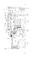
図1から図5に側断面を示す沈胴式のズームレンズ鏡筒10は、被写体側から順に第1レンズ群LG1、シャッタS、第2レンズ群LG2、第3レンズ群LG3、光学フィルタ11及び撮像素子12が配された撮像光学系を有する。この撮像光学系は焦点距離可変のズームレンズ系であり、第1レンズ群LG1と第2レンズ群LG2を撮像光学系の撮影光軸Oに沿って所定の軌跡で進退させることによってズーミングを行う。図2の上半断面がズーム域のワイド端、図2の下半断面がズーム域のテレ端の状態を示している。図3及び図4に示すように、ズームレンズ鏡筒10の所定の繰出位置では、第1レンズ群LG1と第2レンズ群LG2の間(シャッタSの前方)にワイドコンバータレンズWCを挿入して、ズームレンズ系のワイド端よりも短い焦点距離での撮影が可能となる。また、図2ないし図5に示すズームレンズ鏡筒10の撮影状態では、撮影光軸Oに沿って第3レンズ群LG3を移動させることでフォーカシングを行う。図1はズームレンズ鏡筒10の収納(沈胴)状態を示し、この状態では撮影は行われない。以下の説明中で光軸方向とは、撮像光学系の撮影光軸Oと平行な方向を意味し、前方とは光軸方向の前方(被写体側)、後方とは光軸方向の後方(像面側)を意味する。   A collapsible zoom lens barrel 10 whose side sections are shown in FIGS. 1 to 5 includes a first lens group LG1, a shutter S, a second lens group LG2, a third lens group LG3, an optical filter 11, and an image pickup in order from the subject side. It has an imaging optical system in which the element 12 is arranged. This imaging optical system is a zoom lens system having a variable focal length, and performs zooming by moving the first lens group LG1 and the second lens group LG2 along a photographing optical axis O of the imaging optical system along a predetermined locus. The upper half section of FIG. 2 shows the wide end of the zoom range, and the lower half section of FIG. 2 shows the tele end of the zoom range. As shown in FIGS. 3 and 4, at a predetermined extension position of the zoom lens barrel 10, a wide converter lens WC is inserted between the first lens group LG1 and the second lens group LG2 (in front of the shutter S). Thus, it is possible to shoot at a focal length shorter than the wide end of the zoom lens system. In the photographing state of the zoom lens barrel 10 shown in FIGS. 2 to 5, focusing is performed by moving the third lens group LG3 along the photographing optical axis O. FIG. 1 shows a retracted (collapsed) state of the zoom lens barrel 10, and no photographing is performed in this state. In the following description, the optical axis direction means a direction parallel to the imaging optical axis O of the imaging optical system, the front means the front in the optical axis direction (subject side), and the rear means the rear in the optical axis direction (image). Surface side).

ズームレンズ鏡筒10は、固定部材として筒状のハウジング13を備える。ハウジング13の後部に撮像素子ホルダ14が固定され、撮像素子ホルダ14の前面に光学フィルタ11と撮像素子12が支持される。   The zoom lens barrel 10 includes a cylindrical housing 13 as a fixing member. An image sensor holder 14 is fixed to the rear part of the housing 13, and the optical filter 11 and the image sensor 12 are supported on the front surface of the image sensor holder 14.

第3レンズ群LG3は3群枠15に保持されている。3群枠15は、ハウジング13内に固定された光軸方向に延びるガイド軸(図示略)によって光軸方向へ直進移動可能に支持されており、図示を省略するAFモータによって光軸方向に進退駆動される。   The third lens group LG3 is held by the third group frame 15. The third group frame 15 is supported so as to be linearly movable in the optical axis direction by a guide shaft (not shown) fixed in the housing 13 and extending in the optical axis direction, and is advanced and retracted in the optical axis direction by an AF motor (not shown). Driven.

ハウジング13の内側には、3群レンズ枠15の支持駆動手段とは別に、ズームモータ(図示略)により駆動制御される変倍群ブロックが支持されている。変倍群ブロックは、外側繰出筒16、2群レンズブロック17、内側繰出筒(第2の相対移動部材)18及び直進案内環(相対移動部材)19を含んでいる。   In addition to the support driving means for the third group lens frame 15, a zooming group block that is driven and controlled by a zoom motor (not shown) is supported inside the housing 13. The variable power group block includes an outer feeding cylinder 16, a second group lens block 17, an inner feeding cylinder (second relative movement member) 18, and a rectilinear guide ring (relative movement member) 19.

外側繰出筒16と内側繰出筒18はズームレンズ鏡筒10の外観筒を構成している。外側繰出筒16は、ハウジング13の内周面に形成したガイド溝13aに対して摺動可能に嵌るガイド突起16aを有する。外側繰出筒16は、ズームモータにより回転駆動されるズームギヤ(図示略)の駆動力を周面ギヤ16bで受けて回転する。ズームモータを駆動させて外側繰出筒16を回転させると、ガイド溝13aにガイド突起16aが案内されて、外側繰出筒16が回転しながら光軸方向に移動する。具体的には、図1の収納状態から図2ないし図5に示す撮影状態になるときに、外側繰出筒16が回転しながら光軸方向前方に移動する。   The outer feeding cylinder 16 and the inner feeding cylinder 18 constitute an outer appearance cylinder of the zoom lens barrel 10. The outer feeding cylinder 16 has a guide protrusion 16 a that is slidably fitted into a guide groove 13 a formed on the inner peripheral surface of the housing 13. The outer feed cylinder 16 rotates by receiving a driving force of a zoom gear (not shown) rotated by a zoom motor by a peripheral gear 16b. When the outer motor cylinder 16 is rotated by driving the zoom motor, the guide protrusion 16a is guided in the guide groove 13a, and the outer cylinder 16 moves in the optical axis direction while rotating. Specifically, when the shooting state shown in FIGS. 2 to 5 is changed from the housed state of FIG. 1, the outer feeding cylinder 16 moves forward in the optical axis direction while rotating.

直進案内環19は、ハウジング13の内面に形成した直進案内溝(図示略)を介して光軸方向に直進移動可能に案内されている。直進案内環19はまた、外側繰出筒16の内周面に撮影光軸Oを中心として形成した周方向溝16cに対して回転案内突起19aを摺動自在に係合させることで、外側繰出筒16の回転を許しつつ、光軸方向には第2筒16と共に移動する。   The rectilinear guide ring 19 is guided through a rectilinear guide groove (not shown) formed on the inner surface of the housing 13 so as to be linearly movable in the optical axis direction. The rectilinear guide ring 19 is also configured such that the rotation guide projection 19a is slidably engaged with a circumferential groove 16c formed around the photographing optical axis O on the inner peripheral surface of the outer feed cylinder 16, so that the outer feed cylinder 19 is slidably engaged. It moves together with the second tube 16 in the optical axis direction while allowing the rotation of the 16.

2群レンズブロック17は、第2レンズ群LG2を支持する2群支持環(支持部材)20の前部に、シャッタユニット(支持部材)21とコンバータレンズユニット22を取り付けた構成であり、2群支持環20から外径方向に突出する直進案内キー20aを、直進案内環19に形成した光軸方向への長穴である直進案内スロット19b(図6ないし図9)に対して摺動可能に係合させることにより光軸方向へ直進案内されている。シャッタユニット21には、開閉可能なシャッタSと、該シャッタSの開閉駆動を行わせるシャッタアクチュエータ21aが設けられている。シャッタユニット21の前部に支持されるコンバータレンズユニット22の詳細については後述する。   The second group lens block 17 has a configuration in which a shutter unit (support member) 21 and a converter lens unit 22 are attached to a front portion of a second group support ring (support member) 20 that supports the second lens group LG2. A rectilinear guide key 20a protruding in the outer diameter direction from the support ring 20 is slidable with respect to a rectilinear guide slot 19b (FIGS. 6 to 9) which is a long hole in the optical axis direction formed in the rectilinear guide ring 19. By being engaged, it is guided straight in the direction of the optical axis. The shutter unit 21 is provided with a shutter S that can be opened and closed, and a shutter actuator 21 a that opens and closes the shutter S. Details of the converter lens unit 22 supported on the front portion of the shutter unit 21 will be described later.

外側繰出筒16の内周面に形成した2群制御カム溝CG2に対し、2群支持環20に設けた2群用カムフォロアCF2が摺動可能に係合している。2群用カムフォロアCF2は、直進案内キー20aの外径部に設けられ、直進案内環19を径方向に貫通する直進案内スロット19bを通して2群用カムフォロアCF2との係合位置まで突出されている。2群支持環20を含む2群レンズブロック17は直進案内環19を介して光軸方向に直進案内されているため、外側繰出筒16が回転すると、2群制御カム溝CG2の形状に従って、2群レンズブロック17が光軸方向へ所定の軌跡で移動する。   The second group cam follower CF2 provided in the second group support ring 20 is slidably engaged with the second group control cam groove CG2 formed on the inner peripheral surface of the outer feed cylinder 16. The second group cam follower CF2 is provided at the outer diameter portion of the rectilinear guide key 20a, and protrudes to the engagement position with the second group cam follower CF2 through the rectilinear guide slot 19b penetrating the rectilinear guide ring 19 in the radial direction. The second group lens block 17 including the second group support ring 20 is linearly guided in the optical axis direction via the straight guide ring 19, so that when the outer feeding cylinder 16 rotates, the second group control block 20 according to the shape of the second group control cam groove CG2 The group lens block 17 moves along a predetermined locus in the optical axis direction.

内側繰出筒18の内部には撮影光軸Oを囲む筒状のレンズ保持筒18aが設けられ、レンズ保持筒18a内に第1レンズ群LG1が保持されている。内側繰出筒18は、直進案内環19の直進案内スロット19bを介して光軸方向へ直進案内されている。外側繰出筒16の内周面に形成した1群制御カム溝CG1に対し、内側繰出筒18の後端部付近に設けた1群用カムフォロアCF1が摺動可能に係合している。内側繰出筒18は直進案内環19を介して光軸方向に直進案内されているため、外側繰出筒16が回転すると、1群制御カム溝CG1の形状に従って内側繰出筒18が光軸方向へ所定の軌跡で移動する。   A cylindrical lens holding cylinder 18a surrounding the photographing optical axis O is provided inside the inner feeding cylinder 18, and the first lens group LG1 is held in the lens holding cylinder 18a. The inner feeding cylinder 18 is guided in a straight direction in the optical axis direction through a straight guide slot 19 b of the straight guide ring 19. A first group cam follower CF1 provided in the vicinity of the rear end of the inner feeding cylinder 18 is slidably engaged with the first group control cam groove CG1 formed on the inner peripheral surface of the outer feeding cylinder 16. Since the inner feeding cylinder 18 is linearly guided in the optical axis direction via the rectilinear guide ring 19, when the outer feeding cylinder 16 rotates, the inner feeding cylinder 18 is predetermined in the optical axis direction according to the shape of the first group control cam groove CG1. Move along the trajectory.

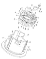
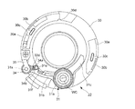
続いてコンバータレンズユニット22について説明する。図6ないし図12に示すように、コンバータレンズユニット22は、支持枠(支持部材)30、挿脱枠31、駆動環(第1の駆動機構、回転駆動部材)32及び駆動環保持枠33を有する。支持枠30はシャッタユニット21の前面側に固定的に支持されており、支持枠30の前面の周縁部には、光軸方向前方に突出し撮影光軸Oを中心とする周方向に向く壁部として、周方向壁30aと一対の係合凸部30bが形成されている。各係合凸部30bは径方向への貫通穴を有している。支持枠30の前面にはさらに、周方向壁30aよりも撮影光軸Oに近い内径側に、周方向位置を異ならせて2つの回転案内突起30cとストッパ30d(図10ないし図12)が形成されている。各回転案内突起30cは、撮影光軸Oを中心とする周方向に長い形状を有している。図10ないし図12に示すように、ストッパ30dは支持枠30の内径方向に突出する凸部として形成されている。支持枠30の外周部には、バネ掛け突起30eと回転制限溝30fが形成されている(図6)。   Next, the converter lens unit 22 will be described. As shown in FIGS. 6 to 12, the converter lens unit 22 includes a support frame (support member) 30, an insertion / removal frame 31, a drive ring (first drive mechanism, rotation drive member) 32, and a drive ring holding frame 33. Have. The support frame 30 is fixedly supported on the front side of the shutter unit 21, and a wall portion that protrudes forward in the optical axis direction and faces in the circumferential direction centering on the photographing optical axis O is formed on the peripheral edge of the front surface of the support frame 30. As shown, a circumferential wall 30a and a pair of engaging projections 30b are formed. Each engagement convex part 30b has a through hole in the radial direction. Two rotation guide protrusions 30c and stoppers 30d (FIGS. 10 to 12) are formed on the front surface of the support frame 30 on the inner diameter side closer to the photographing optical axis O than the circumferential wall 30a with different circumferential positions. Has been. Each rotation guide protrusion 30c has a shape that is long in the circumferential direction about the photographing optical axis O. As shown in FIGS. 10 to 12, the stopper 30 d is formed as a convex portion protruding in the inner diameter direction of the support frame 30. A spring hooking protrusion 30e and a rotation limiting groove 30f are formed on the outer periphery of the support frame 30 (FIG. 6).

挿脱枠31は、筒状のレンズ保持部31a内にワイドコンバータレンズWCを保持し、レンズ保持部31aから異なる方向へ一対のアーム31b、31cを延出させており、アーム31bの先端付近に軸支部31dが形成される。アーム31b上には光軸方向前方へ向けてバネ係合突起(支持部材)31eと被押圧突起31fが突設されている。軸支部31dは撮影光軸Oと平行な回転軸31xにより軸支されており、挿脱枠31は、回転軸31xを中心として、撮影光軸O上にワイドコンバータレンズWCを挿入させる挿入位置(図3、図4、図9及び図12)と、撮影光軸OからワイドコンバータレンズWCを離脱させた退避位置(図1、図2の下半断面、図7及び図10)の間で回転可能である。挿脱枠31の挿入位置はアーム31cの先端付近が支持枠30のストッパ30dに当接することによって決まる。直進案内環19の前端部には径方向に貫通する切欠部19cが形成されており、直進案内環19と2群支持環20の光軸方向における重畳量が大きい状態で挿脱枠31が退避位置まで回転すると、レンズ保持部31aの一部が切欠部19cに進入する(図1)。   The insertion / removal frame 31 holds the wide converter lens WC in a cylindrical lens holding portion 31a, and extends a pair of arms 31b and 31c from the lens holding portion 31a in different directions, and is near the tip of the arm 31b. A shaft support 31d is formed. On the arm 31b, a spring engaging projection (support member) 31e and a pressed projection 31f are provided so as to project forward in the optical axis direction. The shaft support 31d is pivotally supported by a rotation shaft 31x parallel to the photographic optical axis O, and the insertion / removal frame 31 is an insertion position for inserting the wide converter lens WC onto the photographic optical axis O with the rotation shaft 31x as a center. 3, 4, 9, and 12) and the retracted position (the lower half section of FIGS. 1 and 2, FIGS. 7 and 10) where the wide converter lens WC is detached from the imaging optical axis O. Is possible. The insertion position of the insertion / removal frame 31 is determined by the vicinity of the tip of the arm 31c coming into contact with the stopper 30d of the support frame 30. A notch 19c that penetrates in the radial direction is formed at the front end portion of the rectilinear guide ring 19, and the insertion / removal frame 31 is retracted with a large amount of overlap in the optical axis direction between the rectilinear guide ring 19 and the second group support ring 20. When rotated to the position, a part of the lens holding portion 31a enters the cutout portion 19c (FIG. 1).

挿脱枠31の軸支部31dは、トーションバネからなる中間位置保持バネ34のコイル部に挿通されている。軸支部31dの外周面は円筒状をなしており、中間位置保持バネ34は軸支部31dに対して相対回転可能に支持される。中間位置保持バネ34のコイル部から延出される中間位置保持バネ34の一対のバネ腕部34a、34bが、挿脱枠31のアーム31b上に形成したバネ係合突起31eを挟んでおり、中間位置保持バネ34は挿脱枠31に対して挿入位置と退避位置の間の中間位置(図5、図8及び図11)に保持する力を与える。挿脱枠31と中間位置保持バネ34は、支持枠30に対してネジ止めされる保持部材35によって前方から押さえられて、支持枠30からの脱落が規制される。   The shaft support portion 31d of the insertion / removal frame 31 is inserted through the coil portion of the intermediate position holding spring 34 formed of a torsion spring. The outer peripheral surface of the shaft support portion 31d has a cylindrical shape, and the intermediate position holding spring 34 is supported to be rotatable relative to the shaft support portion 31d. A pair of spring arm portions 34a, 34b of the intermediate position holding spring 34 extending from the coil portion of the intermediate position holding spring 34 sandwich a spring engaging protrusion 31e formed on the arm 31b of the insertion / removal frame 31, and The position holding spring 34 applies a force for holding the insertion / removal frame 31 at an intermediate position (FIGS. 5, 8, and 11) between the insertion position and the retracted position. The insertion / removal frame 31 and the intermediate position holding spring 34 are pressed from the front by a holding member 35 that is screwed to the support frame 30, and the drop-off from the support frame 30 is restricted.

挿脱枠31の中間位置と挿入位置の間の回転動作は駆動環32によって行われる。駆動環32は撮影光軸Oを囲む環状体であり、支持枠30の周方向壁30aの内側に保持される。駆動環32には、支持枠30の回転案内突起30cを摺動可能に挿入させる2つの回転案内溝32aが光軸方向に貫通形成されている。回転案内溝32aは撮影光軸Oを中心とする周方向への長溝であり、回転案内溝32aが回転案内突起30cの案内を受けることによって、駆動環32は支持枠30に対して撮影光軸Oを中心として回転可能に支持される。図6に示すように、支持枠30に設けたバネ掛け突起30eと駆動環32の外周面に突設したバネ掛け突起32bに対して、引張バネからなる駆動環付勢バネ(第1の駆動機構、付勢部材)36の一端部と他端部が掛けられており、駆動環付勢バネ36によって駆動環32は図10ないし図12における反時計方向に回転付勢される。駆動環32には外径方向へ突出する駆動突起32cが設けられ、駆動突起32cが支持枠30の回転制限溝30fに挿入されている。図6に示すように、駆動突起32cが回転制限溝30fの一端部に当接することにより、駆動環付勢バネ36による付勢方向への駆動環32の回転が規制される。この駆動環32の回転規制位置を初期位置と呼ぶ。駆動環32にはさらに、中間位置保持バネ34のバネ腕部34aとバネ腕部34bの間に挿入されるバネ操作突起(突出部)32dが設けられている。駆動環32が初期位置に位置するとき、駆動突起32cはバネ腕部34aを押圧せず、挿脱枠31は中間位置保持バネ34の力で中間位置に保持される(図8、図11)。   A rotation operation between the intermediate position of the insertion / removal frame 31 and the insertion position is performed by the drive ring 32. The drive ring 32 is an annular body that surrounds the photographing optical axis O, and is held inside the circumferential wall 30 a of the support frame 30. The drive ring 32 is formed with two rotation guide grooves 32a through which the rotation guide protrusions 30c of the support frame 30 are slidably inserted in the optical axis direction. The rotation guide groove 32 a is a long groove in the circumferential direction centering on the photographing optical axis O, and the driving ring 32 is guided with respect to the support frame 30 by the rotation guide groove 32 a being guided by the rotation guide protrusion 30 c. It is supported rotatably about O. As shown in FIG. 6, a drive ring biasing spring (first drive) composed of a tension spring is applied to a spring hooking protrusion 30e provided on the support frame 30 and a spring hooking protrusion 32b protruding from the outer peripheral surface of the driving ring 32. One end portion and the other end portion of a mechanism (biasing member) 36 are hung, and the drive ring 32 is urged to rotate counterclockwise in FIGS. The drive ring 32 is provided with a drive protrusion 32 c protruding in the outer diameter direction, and the drive protrusion 32 c is inserted into the rotation limiting groove 30 f of the support frame 30. As shown in FIG. 6, the drive projection 32 c abuts on one end of the rotation limiting groove 30 f, thereby restricting the rotation of the drive ring 32 in the biasing direction by the drive ring biasing spring 36. This rotation restriction position of the drive ring 32 is referred to as an initial position. The drive ring 32 is further provided with a spring operation protrusion (protrusion) 32d that is inserted between the spring arm 34a and the spring arm 34b of the intermediate position holding spring 34. When the drive ring 32 is located at the initial position, the drive projection 32c does not press the spring arm 34a, and the insertion / removal frame 31 is held at the intermediate position by the force of the intermediate position holding spring 34 (FIGS. 8 and 11). .

図4、図6ないし図9に示すように、直進案内環19の前端部付近に制御カム(第1の駆動機構、駆動制御部、周面カム)37が形成されている。制御カム37は直進案内環19の内周面に形成した周面カムであり、凹部37aと、該凹部37aの一部を埋める山型形状の押圧部37bを含んでおり、押圧部37bに対して駆動環32の駆動突起32cが当接可能である。より詳しくは、直進案内環19と2群支持環20が光軸方向で所定の位置関係になると、押圧部37bに対して駆動突起32cが当接し、該当接状態で直進案内環19と2群支持環20が光軸方向に相対移動すると、押圧部37bの傾斜形状に沿って駆動突起32cが押圧されて、駆動環32が駆動環付勢バネ36の付勢力に抗する方向に回転される。すると、図12に示すようにバネ操作突起32dがバネ腕部34aを押圧して中間位置保持バネ34を回転させ、中間位置保持バネ34がバネ腕部34bによってバネ係合突起31eを押圧することによって挿脱枠31が挿入位置へ回転される。挿脱枠31はアーム31cをストッパ30dに当接させることにより挿入位置で停止される。   As shown in FIGS. 4 and 6 to 9, a control cam (first drive mechanism, drive control unit, circumferential cam) 37 is formed in the vicinity of the front end portion of the linear guide ring 19. The control cam 37 is a circumferential cam formed on the inner circumferential surface of the linear guide ring 19, and includes a concave portion 37a and a mountain-shaped pressing portion 37b that partially fills the concave portion 37a. Thus, the drive protrusion 32c of the drive ring 32 can come into contact. More specifically, when the linear guide ring 19 and the second group support ring 20 have a predetermined positional relationship in the optical axis direction, the drive protrusion 32c comes into contact with the pressing portion 37b, and the linear guide ring 19 and the second group in the corresponding state. When the support ring 20 relatively moves in the optical axis direction, the drive protrusion 32c is pressed along the inclined shape of the pressing portion 37b, and the drive ring 32 is rotated in a direction against the urging force of the drive ring urging spring 36. . Then, as shown in FIG. 12, the spring operation protrusion 32d presses the spring arm portion 34a to rotate the intermediate position holding spring 34, and the intermediate position holding spring 34 presses the spring engagement protrusion 31e by the spring arm portion 34b. Thus, the insertion / removal frame 31 is rotated to the insertion position. The insertion / removal frame 31 is stopped at the insertion position by bringing the arm 31c into contact with the stopper 30d.

図12は、図6における「B」位置で駆動突起32cが押圧部37bに当接している最大押圧状態を示している。押圧部37bの押圧で与えられる駆動環32の回転量は、中間位置から挿入位置まで挿脱枠31を回転させるために必要な回転量よりも大きく設定されており、図12の状態では、挿脱枠31が挿入位置で回転規制されてからさらに駆動環32が回転された結果、バネ係合突起31eに係合するバネ腕部34bとバネ操作突起32dに係合するバネ腕部34aの間隔を増大させる形で中間位置保持バネ34が撓んで(チャージされて)いる。別言すれば、ある程度の機械的な精度誤差があっても、挿脱枠31を挿入位置まで確実に回転させることができるように、駆動環32の回転量が大きく設定されており、挿脱枠31と駆動環32の回転量の差を中間位置保持バネ34の変形で吸収する構成になっている。挿脱枠31が挿入位置に保持された状態から直進案内環19に対する駆動環32の光軸方向位置が前後に変化すると、押圧部37bによる駆動突起32cの押圧が解除され、駆動環32が駆動環付勢バネ36の付勢力によって図6の初期位置に戻る。また、中間位置保持バネ34の撓みが解放され、駆動環32に伴って挿脱枠31が挿入位置から中間位置に戻る。   FIG. 12 shows a maximum pressing state in which the driving protrusion 32c is in contact with the pressing portion 37b at the position “B” in FIG. The amount of rotation of the drive ring 32 given by the pressing of the pressing portion 37b is set larger than the amount of rotation required to rotate the insertion / removal frame 31 from the intermediate position to the insertion position. In the state of FIG. As a result of the rotation of the drive ring 32 after the frame 31 is restricted from rotation at the insertion position, the distance between the spring arm portion 34b that engages with the spring engagement projection 31e and the spring arm portion 34a that engages with the spring operation projection 32d. The intermediate position holding spring 34 is bent (charged) in such a manner as to increase. In other words, the rotation amount of the drive ring 32 is set large so that the insertion / removal frame 31 can be reliably rotated to the insertion position even if there is some mechanical accuracy error. A difference in rotation amount between the frame 31 and the drive ring 32 is absorbed by deformation of the intermediate position holding spring 34. When the optical axis direction position of the drive ring 32 with respect to the linear guide ring 19 changes back and forth from the state in which the insertion / removal frame 31 is held at the insertion position, the pressing of the driving projection 32c by the pressing portion 37b is released, and the driving ring 32 is driven. Returning to the initial position of FIG. 6 by the biasing force of the ring biasing spring 36. Further, the bending of the intermediate position holding spring 34 is released, and the insertion / removal frame 31 returns from the insertion position to the intermediate position along with the drive ring 32.

駆動環32は駆動環保持枠33によって保持される。駆動環保持枠33は、撮影光軸Oを囲むC字状の部分環状体であり、周方向の両端付近に一対の係合穴33aが形成され、周方向の中間部分に光軸方向後方へ突出する係合突起33bが形成されている。一対の係合穴33aに対して支持枠30に設けた一対の係合凸部30bが挿入される。各係合穴33a内には、係合凸部30bに形成した径方向への貫通穴に係合する突起が形成されており、各係合凸部30bは各係合穴33aに対して抜け止めされる。また、係合突起33bの光軸方向後端部に設けたフック部が係合する係合片部30g(図6)が支持枠30の外周面上に形成されている。これらの係合部分によって駆動環保持枠33が支持枠30に対して固定的に支持される。そして、支持枠30と駆動環保持枠33の間に駆動環32が回転可能に支持される。   The drive ring 32 is held by a drive ring holding frame 33. The drive ring holding frame 33 is a C-shaped partial annular body that surrounds the photographing optical axis O. A pair of engagement holes 33a are formed in the vicinity of both ends in the circumferential direction, and a rearward direction in the optical axis is formed in an intermediate portion in the circumferential direction. A protruding engaging protrusion 33b is formed. A pair of engaging convex portions 30b provided on the support frame 30 is inserted into the pair of engaging holes 33a. Each engagement hole 33a is formed with a protrusion that engages with a radial through hole formed in the engagement protrusion 30b, and each engagement protrusion 30b is detached from each engagement hole 33a. Stopped. An engagement piece 30g (FIG. 6) with which a hook provided at the rear end in the optical axis direction of the engagement protrusion 33b engages is formed on the outer peripheral surface of the support frame 30. The drive ring holding frame 33 is fixedly supported with respect to the support frame 30 by these engaging portions. The drive ring 32 is rotatably supported between the support frame 30 and the drive ring holding frame 33.

挿脱枠31の中間位置と退避位置の間の回転動作は、内側繰出筒18と挿脱枠31の関係によって行われる。図6ないし図10に示すように、内側繰出筒18を構成するレンズ保持筒18aの外周面には退避駆動リブ(第2の駆動機構、第2の駆動制御部40が突出形成されている。退避駆動リブ40は、外径方向への突出量が一定の退避保持部40aと、該退避保持部40aの後端側に位置し、光軸方向後方に進むにつれて徐々に外径方向への突出量を小さくする傾斜部40bを有し、退避保持部40aや傾斜部40bの外縁部に対して挿脱枠31の被押圧突起31fが当接可能である。挿脱枠31と内側繰出筒18の光軸方向の位置関係の変化(内側繰出筒18が光軸方向後方に移動して退避駆動リブ40が挿脱枠31に接近する動作)によって傾斜部40bに対して被押圧突起31fが当接すると、傾斜部40bの傾斜形状に沿って被押圧突起31fが押圧される。すると図10に示すように、バネ係合突起31eでバネ腕部34bを押圧しながら挿脱枠31が中間位置から退避位置へ回転される。挿脱枠31は被押圧突起31fが退避保持部40aに当接することにより退避位置に保持される。挿脱枠31の退避位置への回転に際して駆動環32は回転されず、退避位置に回転した挿脱枠31のバネ係合突起31eで押圧されたバネ腕部34bが、停止した状態の駆動環32のバネ操作突起32dに当接したバネ腕部34aに対する間隔を増大させる形で中間位置保持バネ34が撓んで(チャージされて)いる。別言すれば、中間位置保持バネ34が変形することによって、駆動環32と連動させずに挿脱枠31を単独で退避位置まで回転させることができる。挿脱枠31が退避位置に保持された状態から内側繰出筒18に対する挿脱枠31の光軸方向位置が変化して退避駆動リブ40による被押圧突起31fの押圧が解除されると、挿脱枠31が中間位置保持バネ34の付勢力によって退避位置から中間位置に戻る。   The rotation operation between the intermediate position and the retracted position of the insertion / removal frame 31 is performed by the relationship between the inner feeding cylinder 18 and the insertion / removal frame 31. As shown in FIGS. 6 to 10, a retraction drive rib (second drive mechanism, second drive control unit 40) is formed on the outer peripheral surface of the lens holding cylinder 18 a constituting the inner feeding cylinder 18. The retracting drive rib 40 is positioned on the rear end side of the retracting / holding portion 40a having a constant protrusion amount in the outer diameter direction and the retracting / holding portion 40a, and gradually protrudes in the outer diameter direction as it advances rearward in the optical axis direction. An inclined portion 40b for reducing the amount is provided, and the pressed protrusion 31f of the insertion / removal frame 31 can come into contact with the outer edge portion of the retracting holding portion 40a and the inclination portion 40b. Due to the change in the positional relationship in the optical axis direction (operation in which the inner feeding cylinder 18 moves rearward in the optical axis direction and the retracting drive rib 40 approaches the insertion / removal frame 31), the pressed protrusion 31f is applied to the inclined portion 40b. When in contact, the pressed protrusion along the inclined shape of the inclined portion 40b 10, the insertion / removal frame 31 is rotated from the intermediate position to the retracted position while pressing the spring arm 34b with the spring engagement protrusion 31e, as shown in FIG. The protrusion 31f is held at the retracted position by contacting the retracting holding portion 40a, and the drive ring 32 is not rotated when the inserting / removing frame 31 is rotated to the retracted position, and the spring engagement of the inserting / removing frame 31 rotated to the retracted position. The intermediate position holding spring 34 is bent (charged) in such a manner that the spring arm 34b pressed by the mating protrusion 31e increases the distance from the spring arm 34a abutting against the spring operation protrusion 32d of the drive ring 32 in a stopped state. In other words, when the intermediate position holding spring 34 is deformed, the insertion / removal frame 31 can be independently rotated to the retracted position without interlocking with the drive ring 32. Evacuation position When the position of the insertion / removal frame 31 in the optical axis direction with respect to the inner feeding cylinder 18 changes from the state held in the state and the pressing of the pressed protrusion 31f by the retracting drive rib 40 is released, the insertion / removal frame 31 is moved to the intermediate position holding spring. The urging force 34 returns the retracted position to the intermediate position.

以上の構造からなるズームレンズ鏡筒10は次のように動作する。図1に示す鏡筒収納状態において、ズームレンズ鏡筒10の繰出信号(ズームレンズ鏡筒10が搭載されるカメラのメインスイッチのオンなど)が入力されると、ズームモータが鏡筒繰出方向に駆動されてズームギヤが回転し、外側繰出筒16がハウジング13のガイド溝13aにガイドされて前方へ回転繰出される。直進案内環19は外側繰出筒16と共に前方に直進移動する。外側繰出筒16が回転すると、その内側では、2群制御カム溝CG2と2群用カムフォロアCF2の関係によって、直進案内環19により直進案内された2群支持環20(2群レンズブロック17)が光軸方向に所定の軌跡で移動される。また、外側繰出筒16が回転すると、直進案内環19を介して直進案内された内側繰出筒18が、1群制御カム溝CG1と1群用カムフォロアCF1の関係によって光軸方向に所定の軌跡で移動される。   The zoom lens barrel 10 having the above structure operates as follows. In the lens barrel retracted state shown in FIG. 1, when a feed signal of the zoom lens barrel 10 (such as turning on a main switch of a camera on which the zoom lens barrel 10 is mounted) is input, the zoom motor moves in the barrel feed direction. When driven, the zoom gear rotates, and the outer feed cylinder 16 is guided by the guide groove 13a of the housing 13 and rotated forward. The rectilinear guide ring 19 moves straight forward together with the outer feeding cylinder 16. When the outer feed cylinder 16 rotates, the second group support ring 20 (second group lens block 17) guided linearly by the straight guide ring 19 due to the relationship between the second group control cam groove CG2 and the second group cam follower CF2. It is moved along a predetermined locus in the optical axis direction. When the outer feeding cylinder 16 rotates, the inner feeding cylinder 18 guided linearly through the linear guide ring 19 has a predetermined locus in the optical axis direction due to the relationship between the first group control cam groove CG1 and the first group cam follower CF1. Moved.

鏡筒収納状態からの第1レンズ群LG1と第2レンズ群LG2の繰出量はそれぞれ、ハウジング13に対する外側繰出筒16の前方移動量と、該外側繰出筒16に対する内側繰出筒18、2群支持環20のカム繰出量との合算値として決まる。図2に示すように、ズームレンズ鏡筒10の撮影状態では、第1レンズ群LG1と第2レンズ群LG2が互いの空気間隔を変化させながら撮影光軸O上を移動することにより、ワイド端からテレ端の間で焦点距離が変化する。   The amount of extension of the first lens group LG1 and the second lens group LG2 from the lens barrel storage state is the amount of forward movement of the outer extension cylinder 16 relative to the housing 13, and the inner extension cylinder 18 and the second group support relative to the outer extension cylinder 16, respectively. It is determined as a total value with the cam feed amount of the ring 20. As shown in FIG. 2, when the zoom lens barrel 10 is in the shooting state, the first lens group LG1 and the second lens group LG2 move on the shooting optical axis O while changing the air interval between them. The focal length changes from the telephoto end to the telephoto end.

ズームレンズ鏡筒10の収納信号(カメラのメインスイッチのオフなど)が入力されると、ズームモータが鏡筒収納方向に駆動され、ズームレンズ鏡筒10は上記の繰出動作とは逆の収納動作を行い、図1の収納状態になる。   When a storage signal of the zoom lens barrel 10 (such as turning off the main switch of the camera) is input, the zoom motor is driven in the lens barrel storage direction, and the zoom lens barrel 10 is retracted opposite to the above-described feeding operation. And the storage state shown in FIG. 1 is obtained.

また、ズームレンズ鏡筒10が撮影状態にあるとき、測距手段によって得られた被写体距離情報に応じてAFモータを駆動することにより、第3レンズ群LG3を支持する3群枠15が撮影光軸Oに沿って移動してフォーカシングが実行される。   In addition, when the zoom lens barrel 10 is in the shooting state, the third group frame 15 supporting the third lens group LG3 is driven by the AF light by driving the AF motor in accordance with the subject distance information obtained by the distance measuring means. Moving along the axis O performs focusing.

ズームレンズ鏡筒10の収納状態では、内側繰出筒18に設けた退避駆動リブ40の退避保持部40aが被押圧突起31fを押圧して、挿脱枠31は退避位置に保持される(図1、図7、図10)。このとき駆動環32の駆動突起32cは、直進案内環19の制御カム37に対して図6の「A」位置にあり、駆動環32は押圧部37bに押圧されずに駆動環付勢バネ36の付勢力により初期位置に保持されている。ズームレンズ鏡筒10は、収納状態での薄型化を図るべく、第1レンズ群LG1と第2レンズ群LG2の光軸方向の間隔を小さくさせており、第1レンズ群LG1と第2レンズ群LG2の間にはワイドコンバータレンズWCを収納するスペースを得られない。よって、図1に示すようにワイドコンバータレンズWCが第1レンズ群LG1の外側スペースに収納される退避位置まで挿脱枠31を移動させることで、ワイドコンバータレンズWCと干渉することなく第1レンズ群LG1と第2レンズ群LG2を接近させて、ズームレンズ鏡筒10の収納長を短くすることができる。このとき、ワイドコンバータレンズWCとレンズ保持部31aの一部が切欠部19cに進入することで、直進案内環19と挿脱枠31の干渉を防いでスペース効率に優れた退避状態が実現される。   In the retracted state of the zoom lens barrel 10, the retracting holding portion 40a of the retracting drive rib 40 provided on the inner feeding cylinder 18 presses the pressed protrusion 31f, and the insertion / removal frame 31 is held at the retracted position (FIG. 1). FIG. 7 and FIG. 10). At this time, the drive protrusion 32c of the drive ring 32 is in the “A” position of FIG. 6 with respect to the control cam 37 of the linear guide ring 19, and the drive ring 32 is not pressed by the pressing portion 37b and the drive ring biasing spring 36 is driven. It is held at the initial position by the urging force. In the zoom lens barrel 10, the distance between the first lens group LG1 and the second lens group LG2 in the optical axis direction is reduced in order to reduce the thickness of the zoom lens barrel 10 in the retracted state, and the first lens group LG1 and the second lens group are arranged. A space for accommodating the wide converter lens WC cannot be obtained between LG2. Therefore, as shown in FIG. 1, the first lens is not interfered with the wide converter lens WC by moving the insertion / removal frame 31 to the retracted position where the wide converter lens WC is accommodated in the outer space of the first lens group LG1. The storage length of the zoom lens barrel 10 can be shortened by bringing the group LG1 and the second lens group LG2 close to each other. At this time, the wide converter lens WC and a part of the lens holding portion 31a enter the cutout portion 19c, thereby preventing the rectilinear guide ring 19 and the insertion / removal frame 31 from interfering with each other and realizing a retreat state with excellent space efficiency. .

ズームレンズ鏡筒10が収納状態から繰り出されるとき、2群支持環20(2群レンズブロック17)よりも内側繰出筒18の方が光軸方向前方への移動量が大きいため、退避駆動リブ40が被押圧突起31fに対する押圧を解除して、挿脱枠31の退避位置への保持が解除される。すると、挿脱枠31が中間位置保持バネ34の付勢力によって退避位置から中間位置に回転される。ズームレンズ鏡筒10がさらに繰り出されると、2群支持環20(2群レンズブロック17)が直進案内環19に対して光軸方向前方に繰り出され、制御カム37に対する駆動突起32cの位置が図6の「A」位置から「B」位置に変化する。すると押圧部37bが駆動突起32cを押圧して、駆動環32が駆動環付勢バネ36の付勢力に抗して初期位置から回転され、中間位置保持バネ34を介して挿脱枠31を挿入位置へ回転させる(図3、図4、図9、図12)。これによりワイドコンバータレンズWCが撮影光軸O上に挿入され、ズームレンズ系のワイド端よりも焦点距離が短いスーパーワイド状態になる。   When the zoom lens barrel 10 is extended from the retracted state, the inner extension cylinder 18 has a larger amount of movement forward in the optical axis direction than the second group support ring 20 (second group lens block 17). Releases the pressure on the pressed protrusion 31f, and the holding of the insertion / removal frame 31 in the retracted position is released. Then, the insertion / removal frame 31 is rotated from the retracted position to the intermediate position by the biasing force of the intermediate position holding spring 34. When the zoom lens barrel 10 is further extended, the second group support ring 20 (second group lens block 17) is extended forward in the optical axis direction with respect to the linear guide ring 19, and the position of the drive protrusion 32c with respect to the control cam 37 is illustrated. 6 changes from the “A” position to the “B” position. Then, the pressing portion 37b presses the drive protrusion 32c, the drive ring 32 is rotated from the initial position against the urging force of the drive ring urging spring 36, and the insertion / removal frame 31 is inserted via the intermediate position holding spring 34. Rotate to position (FIGS. 3, 4, 9, 12). As a result, the wide converter lens WC is inserted on the photographing optical axis O, and a super-wide state is obtained in which the focal length is shorter than the wide end of the zoom lens system.

スーパーワイド状態からズームレンズ鏡筒10が繰り出されると、2群支持環20(2群レンズブロック17)が直進案内環19に対して光軸方向前方に繰り出され、制御カム37に対する駆動突起32cの位置が図6の「B」位置から「C」位置に変化する。すると、押圧部37bによる駆動突起32cの押圧が解除され、駆動環32が駆動環付勢バネ36の付勢力によって初期位置に復帰すると共に、挿脱枠31が挿入位置から中間位置に回転する(図5、図8、図11)。挿脱枠31の中間位置ではワイドコンバータレンズWCが撮影光路の外側に位置しており、ワイドコンバータレンズWCは撮影に関与しなくなる。   When the zoom lens barrel 10 is extended from the super wide state, the second group support ring 20 (second group lens block 17) is extended forward in the optical axis direction with respect to the linear guide ring 19, and the drive protrusion 32c with respect to the control cam 37 is extended. The position changes from the “B” position in FIG. 6 to the “C” position. Then, the pressing of the driving projection 32c by the pressing portion 37b is released, the driving ring 32 returns to the initial position by the biasing force of the driving ring biasing spring 36, and the insertion / removal frame 31 rotates from the insertion position to the intermediate position ( 5, FIG. 8, FIG. 11). At the middle position of the insertion / removal frame 31, the wide converter lens WC is positioned outside the photographing optical path, and the wide converter lens WC is not involved in photographing.

図6に示す「C」位置はズームレンズ鏡筒10のワイド端(図2の上半断面)、「D」位置はズームレンズ鏡筒10のテレ端(図2の下半断面)における駆動突起32cの位置である。図6から分かるように、ワイド端からテレ端までのズーム域では、駆動突起32cが制御カム37から前方に離脱しており、駆動環32は初期位置に保持され続ける。つまり、通常のズーム域では挿脱枠31が挿入位置へ回転されることはない。ズーム域のほとんどで、挿脱枠31は中間位置保持バネ34によって中間位置に保持されるが、図2の下半に示すテレ端付近では、第1レンズ群LG1と第2レンズ群LG2の光軸方向間隔が小さくなることに伴い、挿脱枠31に対して退避駆動リブ40が接近して該退避駆動リブ40で被押圧突起31fを押圧し、挿脱枠31が退避位置に回転される。収納状態と同様に、テレ端では第1レンズ群LG1と第2レンズ群LG2の間隔が小さくなって光軸方向のスペースが狭くなるため、挿脱枠31を退避位置へ回転させることによって第1レンズ群LG1とワイドコンバータレンズWCの干渉を防ぐことができる。   The “C” position shown in FIG. 6 is the driving end at the wide end (upper half section of FIG. 2) of the zoom lens barrel 10, and the “D” position is the driving projection at the tele end (lower half section of FIG. 2) of the zoom lens barrel 10. It is the position of 32c. As can be seen from FIG. 6, in the zoom range from the wide end to the tele end, the drive protrusion 32c is detached forward from the control cam 37, and the drive ring 32 continues to be held at the initial position. That is, the insertion / removal frame 31 is not rotated to the insertion position in the normal zoom range. In most of the zoom range, the insertion / removal frame 31 is held at the intermediate position by the intermediate position holding spring 34, but in the vicinity of the telephoto end shown in the lower half of FIG. 2, the light of the first lens group LG1 and the second lens group LG2 As the axial interval becomes smaller, the retracting drive rib 40 approaches the inserting / removing frame 31 and presses the pressed protrusion 31f with the retracting drive rib 40, and the inserting / removing frame 31 is rotated to the retracted position. . As in the retracted state, the distance between the first lens group LG1 and the second lens group LG2 becomes smaller at the telephoto end, and the space in the optical axis direction becomes narrower. Therefore, the first insertion / removal frame 31 is rotated to the retracted position. Interference between the lens group LG1 and the wide converter lens WC can be prevented.

以上のように、本実施形態のズームレンズ鏡筒10では、ワイドコンバータレンズWCを保持する挿脱枠31を駆動させる機構として、挿入位置と中間位置の間の駆動を行わせる第1の駆動機構と、中間位置と退避位置の間の駆動を行わせる第2の駆動機構を備えている。第1の駆動機構と第2の駆動機構でコンバータレンズWCの駆動範囲を分担することで、個々の駆動機構をスペースや配置の制約が少ない小型な構造とすることができる。   As described above, in the zoom lens barrel 10 of the present embodiment, as the mechanism for driving the insertion / removal frame 31 that holds the wide converter lens WC, the first drive mechanism for driving between the insertion position and the intermediate position. And a second drive mechanism for driving between the intermediate position and the retracted position. By sharing the drive range of the converter lens WC with the first drive mechanism and the second drive mechanism, it is possible to make each drive mechanism a small structure with less space and arrangement restrictions.

例えば、中間位置保持バネ34は、挿脱枠31が挿入位置から中間位置までの範囲にあるときには、回転軸31xを中心とする回転によって駆動環32の回転を挿脱枠31に伝達し、挿脱枠31が中間位置から退避位置に回転したときには、挿脱枠31を中間位置に復帰させる付勢手段として機能する。これにより、バネ腕部34a、34bの長さを短くして中間位置保持バネ34の小型化を図ることができる。仮に、挿脱枠31の中間位置を設定せずに、退避位置から挿入位置まで挿脱枠31が回転するにつれて徐々に撓み量が大きくなるようなトーションバネによって挿脱枠31を退避位置方向へ付勢した場合、本実施形態の中間位置保持バネ34のバネ腕部34a、34bに比して長いバネ腕部が必要となり、駆動機構が大型化してしまう。   For example, when the insertion / removal frame 31 is in the range from the insertion position to the intermediate position, the intermediate position holding spring 34 transmits the rotation of the drive ring 32 to the insertion / removal frame 31 by rotation about the rotation shaft 31x. When the unframe 31 rotates from the intermediate position to the retracted position, it functions as an urging means for returning the insertion / removal frame 31 to the intermediate position. Thereby, the length of the spring arm portions 34a and 34b can be shortened, and the intermediate position holding spring 34 can be downsized. Even if the intermediate position of the insertion / removal frame 31 is not set, the insertion / removal frame 31 is moved in the direction of the retraction position by a torsion spring whose amount of bending gradually increases as the insertion / removal frame 31 rotates from the retraction position to the insertion position. When energized, spring arm portions that are longer than the spring arm portions 34a and 34b of the intermediate position holding spring 34 of the present embodiment are required, and the drive mechanism becomes large.

また、ワイドコンバータレンズWCの退避量が小さい中間位置とコンバータレンズの退避量が大きい退避位置をズームレンズ鏡筒10の繰出状態に応じて使い分けることにより、ズームレンズ鏡筒10内でワイドコンバータレンズWCを効率良く収納でき、ワイドコンバータレンズWCを駆動する第1の駆動機構と第2の駆動機構の小型化や簡略化も図ることができる。具体的には、図1に示すズームレンズ鏡筒10の収納状態や、図2の下半に示すズームレンズ鏡筒10のテレ端付近では、第1レンズ群LG1と第2レンズ群LG2の光軸方向間隔が小さくなるため、第1レンズ群LG1に干渉しない退避位置まで挿脱枠31を回転させる。この退避位置までの挿脱枠31の回転駆動は、第1レンズ群LG1を保持する内側繰出筒18に設けた退避駆動リブ40の押圧によって行われるため、内側繰出筒18の光軸方向の移動力を用いて簡単な構成で挿脱枠31を回転させることができる。図5のように、テレ端付近を除くズーム域では、小型の中間位置保持バネ34によって挿脱枠31が中間位置に保持される。さらにワイド端と収納状態の間のスーパーワイド状態では、テレ端からワイド端までのズーム域よりもコンバータレンズユニット22が直進案内環19に接近することを利用して、直進案内環19に形成した制御カム37の押圧部37bによって駆動環32を押圧回転して、挿脱枠31を挿入位置へ回転させる。駆動環32が挿脱枠31に与える回転量は中間位置から挿入位置まであり、退避位置から挿入位置まで回転させる構成に比して、駆動環32の回転量を小さくすることができる。   Further, by selectively using an intermediate position where the retracting amount of the wide converter lens WC is small and a retracting position where the retracting amount of the converter lens is large according to the extended state of the zoom lens barrel 10, the wide converter lens WC within the zoom lens barrel 10. The first drive mechanism and the second drive mechanism for driving the wide converter lens WC can be reduced in size and simplified. Specifically, in the retracted state of the zoom lens barrel 10 shown in FIG. 1 and in the vicinity of the tele end of the zoom lens barrel 10 shown in the lower half of FIG. 2, the light of the first lens group LG1 and the second lens group LG2 Since the axial interval is small, the insertion / removal frame 31 is rotated to the retracted position where it does not interfere with the first lens group LG1. The rotational drive of the insertion / removal frame 31 to the retracted position is performed by pressing the retracting drive rib 40 provided on the inner feeding cylinder 18 that holds the first lens group LG1, so that the inner feeding cylinder 18 moves in the optical axis direction. The insertion / removal frame 31 can be rotated with a simple configuration using force. As shown in FIG. 5, in the zoom range excluding the vicinity of the telephoto end, the insertion / removal frame 31 is held at the intermediate position by the small intermediate position holding spring 34. Further, in the super wide state between the wide end and the retracted state, the converter lens unit 22 is formed on the straight guide ring 19 by utilizing the fact that the converter lens unit 22 is closer to the straight guide ring 19 than the zoom range from the tele end to the wide end. The drive ring 32 is pressed and rotated by the pressing portion 37b of the control cam 37, and the insertion / removal frame 31 is rotated to the insertion position. The rotation amount that the drive ring 32 gives to the insertion / removal frame 31 is from the intermediate position to the insertion position, and the rotation amount of the drive ring 32 can be reduced as compared with the configuration that rotates from the retracted position to the insertion position.

以上、図示実施形態に基づき説明したが、本発明はこれに限定されるものではない。例えば、実施形態のズームレンズ鏡筒10では、撮影光軸O上に挿脱される光学要素をワイドコンバータレンズWCとしたが、テレ端よりも焦点距離を長くさせるテレコンバーターレンズの駆動機構に本発明を用いることも可能である。ズームレンズ鏡筒10のズームレンズ系は、収納状態から繰り出し動作を行うとワイド端になり、さらに繰り出し動作を行うとテレ端になるが、収納状態からの繰り出し動作で最初にテレ端になるタイプのズームレンズ系の場合は、図示実施形態と同様の駆動機構によってテレコンバーターレンズの駆動を実現できる。   As mentioned above, although demonstrated based on illustration embodiment, this invention is not limited to this. For example, in the zoom lens barrel 10 of the embodiment, the optical element inserted into and removed from the photographing optical axis O is the wide converter lens WC, but the present invention is a teleconverter lens driving mechanism that makes the focal length longer than the tele end. It is also possible to use. The zoom lens system of the zoom lens barrel 10 is a wide end when the extension operation is performed from the retracted state, and a tele end when the extension operation is further performed. In the case of this zoom lens system, the teleconverter lens can be driven by the same drive mechanism as in the illustrated embodiment.

また、実施形態のズームレンズ鏡筒10では、収納状態からズーム域になる途中で挿脱枠31が挿入位置に移動されるが、ズーム域よりも繰り出した位置でコンバータレンズが光軸上に挿入されるタイプのレンズ鏡筒に本発明を適用することも可能である。   In the zoom lens barrel 10 of the embodiment, the insertion / removal frame 31 is moved to the insertion position in the middle of the zoom range from the housed state, but the converter lens is inserted on the optical axis at a position extended from the zoom range. It is also possible to apply the present invention to a lens barrel of the type.

また、実施形態のズームレンズ鏡筒10では、光軸方向に直進移動する内側繰出筒18や直進案内環19によって挿脱枠31や駆動環32を回転駆動させているが、光軸方向への直進移動部材ではなく、外側繰出筒16のような回転部材によってコンバータレンズの駆動機構に駆動力を付与する構成を採用することもできる。   In the zoom lens barrel 10 of the embodiment, the insertion / removal frame 31 and the drive ring 32 are rotationally driven by the inner feeding cylinder 18 and the rectilinear guide ring 19 that move linearly in the optical axis direction. A configuration in which a driving force is applied to the drive mechanism of the converter lens by a rotating member such as the outer feeding cylinder 16 instead of the rectilinearly moving member may be employed.

本発明は、実施形態のズームレンズ鏡筒10のような3群構成以外のズームレンズ系にも適用が可能である。また、コンバータレンズの挿入位置は、第1レンズ群LG1と第2レンズ群LG2の間以外にも設定が可能である。   The present invention can also be applied to zoom lens systems other than the three-group configuration such as the zoom lens barrel 10 of the embodiment. The insertion position of the converter lens can be set other than between the first lens group LG1 and the second lens group LG2.

10 ズームレンズ鏡筒
11 光学フィルタ
12 撮像素子
13 ハウジング
14 撮像素子ホルダ
15 3群枠
16 外側繰出筒
17 2群レンズブロック
18 内側繰出筒(第2の相対移動部材)
18a レンズ保持筒
19 直進案内環(相対移動部材)
20 2群支持環(支持部材)
21 シャッタユニット(支持部材)
22 コンバータレンズユニット
30 支持枠(支持部材)
30a 周方向壁
30b 係合凸部
30c 回転案内突起
30d ストッパ
30e バネ掛け突起
30f 回転制限溝
30g 係合片部
31 挿脱枠
31a レンズ保持部
31b 31c アーム
31d 軸支部
31e バネ係合突起(突出部)
31f 被押圧突起
31x 回転軸
32 駆動環(第1の駆動機構、回転駆動部材)
32a 回転案内溝
32b バネ掛け突起
32c 駆動突起
32d バネ操作突起(突出部)
33 駆動環保持枠
33a 係合穴
33b 係合突起
34 中間位置保持バネ(トーションバネ)
34a 34b バネ腕部
35 保持部材
36 駆動環付勢バネ(第1の駆動機構、付勢部材)
37 制御カム(第1の駆動機構、駆動制御部、周面カム)
37a 凹部
37b 押圧部
40 退避駆動リブ(第2の駆動機構、第2の駆動制御部)
40a 退避保持部
40b 傾斜部
CF1 1群用カムフォロア
CF2 2群用カムフォロア
CG1 1群制御カム溝
CG2 2群制御カム溝
LG1 第1レンズ群
LG2 第2レンズ群
LG3 第3レンズ群
O 撮影光軸
S シャッタ
WC ワイドコンバータレンズ
DESCRIPTION OF SYMBOLS 10 Zoom lens barrel 11 Optical filter 12 Image pick-up element 13 Housing 14 Image pick-up element holder 15 3 group frame 16 Outer delivery cylinder 17 2nd lens block 18 Inner delivery cylinder (2nd relative movement member)
18a Lens holding cylinder 19 Linear guide ring (relative movement member)
20 Group 2 support ring (support member)
21 Shutter unit (supporting member)
22 Converter lens unit 30 Support frame (support member)
30a Circumferential wall 30b Engaging protrusion 30c Rotating guide protrusion 30d Stopper 30e Spring hooking protrusion 30f Rotation limiting groove 30g Engaging piece 31 Inserting / removing frame 31a Lens holding part 31b 31c Arm 31d Shaft support 31e Spring engaging protrusion (protruding part) )
31f Pressed protrusion 31x Rotating shaft 32 Drive ring (first drive mechanism, rotation drive member)
32a Rotation guide groove 32b Spring hooking protrusion 32c Drive protrusion 32d Spring operation protrusion (protrusion)
33 Drive ring holding frame 33a Engaging hole 33b Engaging projection 34 Intermediate position holding spring (torsion spring)
34a 34b Spring arm portion 35 Holding member 36 Drive ring biasing spring (first driving mechanism, biasing member)
37 control cam (first drive mechanism, drive control unit, circumferential cam)
37a Concave part 37b Pressing part 40 Retraction driving rib (second driving mechanism, second driving control part)
40a Retraction holding portion 40b Inclination portion CF1 First group cam follower CF2 Second group cam follower CG1 First group control cam groove CG2 Second group control cam groove LG1 First lens group LG2 Second lens group LG3 Third lens group O Shooting optical axis S Shutter WC Wide converter lens

Claims (10)

光軸方向に移動する複数のレンズ群を含み、焦点距離可変のズームレンズ系;
上記ズームレンズ系の光軸上に挿入されることにより該ズームレンズ系の焦点距離範囲外の焦点距離での撮影を可能にするコンバータレンズ;及び
上記コンバータレンズを上記ズームレンズ系の光軸上への挿入位置と上記光軸上から離脱した退避位置との間で移動させるコンバータレンズ駆動機構;
を備えたレンズ鏡筒において、
上記コンバータレンズ駆動機構は、
上記コンバータレンズを、上記挿入位置と、該挿入位置と上記退避位置の中間に位置し上記ズームレンズ系の撮影光路に干渉しない中間位置との間で移動させる第1の駆動機構;及び
上記コンバータレンズを、上記中間位置と上記退避位置との間で移動させる第2の駆動機構;
を有し、
撮影を行わないレンズ鏡筒の収納状態では、上記第2の駆動機構によって上記コンバータレンズが上記退避位置に位置され、上記ズームレンズ系の上記焦点距離範囲の少なくとも一部では上記第1の駆動機構によって上記コンバータレンズが上記中間位置に位置されることを特徴とするレンズ鏡筒。
A zoom lens system including a plurality of lens groups moving in the optical axis direction and having a variable focal length;
A converter lens that is inserted on the optical axis of the zoom lens system to enable photographing at a focal length outside the focal length range of the zoom lens system; and the converter lens onto the optical axis of the zoom lens system. A converter lens drive mechanism that moves between the insertion position of the lens and the retracted position separated from the optical axis;
In a lens barrel with
The converter lens drive mechanism is
A first drive mechanism that moves the converter lens between the insertion position and an intermediate position that is intermediate between the insertion position and the retracted position and does not interfere with the imaging optical path of the zoom lens system; and the converter lens A second drive mechanism for moving the motor between the intermediate position and the retracted position;
Have
In the retracted state of the lens barrel that is not photographed, the converter lens is positioned at the retracted position by the second driving mechanism, and the first driving mechanism is at least partly in the focal length range of the zoom lens system. The lens barrel is characterized in that the converter lens is positioned at the intermediate position.
請求項1記載のレンズ鏡筒において、
上記コンバータレンズを保持する挿脱枠;
上記挿脱枠を上記ズームレンズ系の光軸と平行な回転軸を中心に回転可能に支持する支持部材;及び
上記複数のレンズ群を光軸方向に移動させるときに上記支持部材に対する相対移動を行う相対移動部材;
を有し、
上記第1の駆動機構は、
上記支持部材に支持され、上記挿脱枠の回転軸と平行な軸を中心とする回転によって、上記コンバータレンズの上記挿入位置と上記中間位置に上記挿脱枠を移動させる回転駆動部材;及び
上記相対移動部材に形成され、上記支持部材に対する上記相対移動部材の相対移動によって上記回転駆動部材に対して当接及び当接解除して該回転駆動部材の回転方向位置を変化させる駆動制御部;
を有しているレンズ鏡筒。
The lens barrel according to claim 1,
An insertion / removal frame for holding the converter lens;
A support member that rotatably supports the insertion / removal frame about a rotation axis parallel to the optical axis of the zoom lens system; and a relative movement with respect to the support member when the plurality of lens groups are moved in the optical axis direction. Relative movement member to perform;
Have
The first drive mechanism includes:
A rotation drive member supported by the support member and configured to move the insertion / removal frame to the insertion position and the intermediate position of the converter lens by rotation about an axis parallel to a rotation axis of the insertion / removal frame; A drive control unit that is formed on the relative movement member and changes the position of the rotation drive member in the rotation direction by contacting and releasing the rotation drive member by relative movement of the relative movement member with respect to the support member;
A lens barrel.
請求項2記載のレンズ鏡筒において、上記第1の駆動機構は、上記コンバータレンズの上記中間位置に対応する初期位置に上記回転駆動部材を保持させる付勢部材を有し、
上記駆動制御部は、上記支持部材と上記相対移動部材の相対移動によって上記回転駆動部材に当接して、該回転駆動部材を上記挿入付勢部材の付勢力に抗して上記初期位置から押圧回転させるレンズ鏡筒。
3. The lens barrel according to claim 2, wherein the first drive mechanism includes a biasing member that holds the rotation drive member at an initial position corresponding to the intermediate position of the converter lens,
The drive control unit abuts on the rotation drive member by relative movement of the support member and the relative movement member, and rotates the rotation drive member from the initial position against the biasing force of the insertion biasing member. The lens barrel to be made.
請求項2または3記載のレンズ鏡筒において、上記相対移動部材は、光軸方向へ直進移動可能に支持され、上記複数のレンズ群を光軸方向に移動させるときに上記支持部材に対して光軸方向に相対移動するレンズ鏡筒。 4. The lens barrel according to claim 2, wherein the relative movement member is supported so as to be linearly movable in the optical axis direction, and light is applied to the support member when the plurality of lens groups are moved in the optical axis direction. A lens barrel that moves in the axial direction. 請求項4記載のレンズ鏡筒において、上記相対移動部材は、上記支持部材を光軸方向に移動可能に案内する直進案内環であり、上記駆動制御部は、上記直進案内環の周面に形成された周面カムからなるレンズ鏡筒。 5. The lens barrel according to claim 4, wherein the relative movement member is a rectilinear guide ring that guides the support member so as to be movable in an optical axis direction, and the drive control unit is formed on a peripheral surface of the rectilinear guide ring. A lens barrel made of a circumferential cam. 請求項2ないし5のいずれか1項記載のレンズ鏡筒において、上記挿脱枠に設けた突出部と上記回転駆動部材に設けた突出部を一対のバネ腕部の間に挿入させ、上記挿脱枠の上記回転軸を中心として回転可能なトーションバネを有し、
上記トーションバネにより上記コンバータレンズの上記中間位置に上記挿脱枠が保持され、上記一対のバネ腕部を介して上記回転駆動部材の回転方向の力が上記挿脱枠に伝達されるレンズ鏡筒。
6. The lens barrel according to claim 2, wherein the protrusion provided on the insertion / removal frame and the protrusion provided on the rotation drive member are inserted between a pair of spring arm portions, and the insertion is performed. Having a torsion spring rotatable around the rotation axis of the unframed,
The lens barrel in which the insertion / removal frame is held at the intermediate position of the converter lens by the torsion spring, and the rotational force of the rotation driving member is transmitted to the insertion / removal frame via the pair of spring arms. .
請求項6記載のレンズ鏡筒において、上記第2の駆動機構は、上記複数のレンズ群を光軸方向に移動させるときに上記支持部材に対する相対移動を行う第2の相対移動部材に形成され、上記支持部材に対する上記第2の相対移動部材の相対移動によって上記挿脱枠に対して当接及び当接解除し、該挿脱枠を押圧して上記コンバータレンズを上記退避位置に移動させる第2の駆動制御部を有しているレンズ鏡筒。 7. The lens barrel according to claim 6, wherein the second drive mechanism is formed on a second relative movement member that moves relative to the support member when the plurality of lens groups are moved in the optical axis direction. A second movement of the second relative movement member with respect to the support member causes contact and release of the insertion / removal frame, and presses the insertion / removal frame to move the converter lens to the retracted position. A lens barrel having a drive control unit. 請求項7記載のレンズ鏡筒において、上記第2の相対移動部材は、光軸方向へ直進移動可能に支持され、上記複数のレンズ群を光軸方向に移動させるときに上記支持部材に対して光軸方向に相対移動するレンズ鏡筒。 8. The lens barrel according to claim 7, wherein the second relative movement member is supported so as to be linearly movable in the optical axis direction, and moves relative to the support member when the plurality of lens groups are moved in the optical axis direction. A lens barrel that moves relative to the optical axis. 請求項8記載のレンズ鏡筒において、上記第2の相対移動部材は、上記複数のレンズ群の少なくとも1つを保持するレンズ保持筒部を内部に有する筒状部材であり、上記第2の駆動制御部は、上記レンズ保持筒部から外径方向に突出する突出部からなるレンズ鏡筒。 9. The lens barrel according to claim 8, wherein the second relative movement member is a cylindrical member having therein a lens holding cylinder portion that holds at least one of the plurality of lens groups, and the second driving unit. The control unit is a lens barrel including a protruding portion protruding in the outer diameter direction from the lens holding tube portion. 請求項9記載のレンズ鏡筒において、上記支持部材は上記複数のレンズ群の少なくとも1つを保持しており、
上記第2の相対移動部材に保持される上記レンズ群は、上記支持部材に保持される上記レンズ群よりも被写体側に位置し、
上記コンバータレンズは、上記第2の相対移動部材に保持される上記レンズ群と上記支持部材に保持される上記レンズ群との間に挿入されるレンズ鏡筒。
The lens barrel according to claim 9, wherein the support member holds at least one of the plurality of lens groups,
The lens group held by the second relative movement member is located closer to the subject than the lens group held by the support member,
The converter lens is a lens barrel inserted between the lens group held by the second relative movement member and the lens group held by the support member.
JP2012257488A 2012-11-26 2012-11-26 Lens barrel Pending JP2014106277A (en)

Priority Applications (1)

Application Number Priority Date Filing Date Title
JP2012257488A JP2014106277A (en) 2012-11-26 2012-11-26 Lens barrel

Applications Claiming Priority (1)

Application Number Priority Date Filing Date Title
JP2012257488A JP2014106277A (en) 2012-11-26 2012-11-26 Lens barrel

Publications (1)

Publication Number Publication Date
JP2014106277A true JP2014106277A (en) 2014-06-09

Family

ID=51027851

Family Applications (1)

Application Number Title Priority Date Filing Date
JP2012257488A Pending JP2014106277A (en) 2012-11-26 2012-11-26 Lens barrel

Country Status (1)

Country Link
JP (1) JP2014106277A (en)

Cited By (2)

* Cited by examiner, † Cited by third party
Publication number Priority date Publication date Assignee Title
KR20160121386A (en) * 2015-04-09 2016-10-19 삼성전자주식회사 Lens barrel and optical device
JP2016200791A (en) * 2015-04-09 2016-12-01 三星電子株式会社Samsung Electronics Co.,Ltd. Lens barrel and optical instrument

Cited By (3)

* Cited by examiner, † Cited by third party
Publication number Priority date Publication date Assignee Title
KR20160121386A (en) * 2015-04-09 2016-10-19 삼성전자주식회사 Lens barrel and optical device
JP2016200791A (en) * 2015-04-09 2016-12-01 三星電子株式会社Samsung Electronics Co.,Ltd. Lens barrel and optical instrument
KR102542912B1 (en) 2015-04-09 2023-06-15 삼성전자주식회사 Lens barrel and optical device

Similar Documents

Publication Publication Date Title
JP4520190B2 (en) Retractable lens barrel and camera equipped with a retractable lens barrel
JP4969859B2 (en) Lens barrel
JP5788203B2 (en) Lens barrel
JP5079277B2 (en) Lens barrel
JP4969863B2 (en) Lens barrel
JP4959407B2 (en) Lens driving device, zoom lens driving device, and camera
JP2008170650A (en) Lens barrel
JP4817877B2 (en) LENS DEVICE AND IMAGING DEVICE
JP5446154B2 (en) Lens barrel, optical equipment
JP5122346B2 (en) Lens barrel
KR20130043147A (en) Lens barrel
JP2011154347A (en) Lens barrel
JP2009251063A (en) Lens barrel
JP2007248608A (en) Lens barrel and camera
JP2011154204A (en) Photographing device
JP2011099979A (en) Zoom lens barrel
JP2007033961A (en) Lens driving apparatus
US8964306B2 (en) Lens barrel
JP5012919B2 (en) Lens barrel and optical device
JP5201811B2 (en) Lens barrel and imaging device
WO2010008015A1 (en) Lens barrel and optical device
US7864458B2 (en) Lens barrel
JP2010014786A (en) Light-shielding member-supporting structure of lens barrel
JP2014106277A (en) Lens barrel
US6906871B2 (en) Cam mechanism for lens barrel

Legal Events

Date Code Title Description
RD04 Notification of resignation of power of attorney

Free format text: JAPANESE INTERMEDIATE CODE: A7424

Effective date: 20150130