JP6156747B2 - Electrostatic encoder - Google Patents

Electrostatic encoder Download PDF

Info

Publication number
JP6156747B2
JP6156747B2 JP2014255350A JP2014255350A JP6156747B2 JP 6156747 B2 JP6156747 B2 JP 6156747B2 JP 2014255350 A JP2014255350 A JP 2014255350A JP 2014255350 A JP2014255350 A JP 2014255350A JP 6156747 B2 JP6156747 B2 JP 6156747B2
Authority
JP
Japan
Prior art keywords
electrode
detection
electrodes
transmission
rotor
Prior art date
Legal status (The legal status is an assumption and is not a legal conclusion. Google has not performed a legal analysis and makes no representation as to the accuracy of the status listed.)
Active
Application number
JP2014255350A
Other languages
Japanese (ja)
Other versions
JP2016114559A (en
JP2016114559A5 (en
Inventor
大生 近藤
大生 近藤
Current Assignee (The listed assignees may be inaccurate. Google has not performed a legal analysis and makes no representation or warranty as to the accuracy of the list.)
Oriental Motor Co Ltd
Original Assignee
Oriental Motor Co Ltd
Priority date (The priority date is an assumption and is not a legal conclusion. Google has not performed a legal analysis and makes no representation as to the accuracy of the date listed.)
Filing date
Publication date
Priority to JP2014255350A priority Critical patent/JP6156747B2/en
Application filed by Oriental Motor Co Ltd filed Critical Oriental Motor Co Ltd
Priority to CN201580068399.XA priority patent/CN107003154B/en
Priority to PCT/JP2015/084130 priority patent/WO2016098613A1/en
Priority to US15/536,357 priority patent/US10551219B2/en
Priority to EP15869818.3A priority patent/EP3236214B1/en
Priority to KR1020177019622A priority patent/KR101957957B1/en
Priority to EP18212505.4A priority patent/EP3486614B1/en
Priority to TW104142073A priority patent/TWI681172B/en
Priority to TW108130267A priority patent/TWI699515B/en
Publication of JP2016114559A publication Critical patent/JP2016114559A/en
Publication of JP2016114559A5 publication Critical patent/JP2016114559A5/ja
Application granted granted Critical
Publication of JP6156747B2 publication Critical patent/JP6156747B2/en
Active legal-status Critical Current
Anticipated expiration legal-status Critical

Links

Images

Classifications

    • GPHYSICS
    • G01MEASURING; TESTING
    • G01DMEASURING NOT SPECIALLY ADAPTED FOR A SPECIFIC VARIABLE; ARRANGEMENTS FOR MEASURING TWO OR MORE VARIABLES NOT COVERED IN A SINGLE OTHER SUBCLASS; TARIFF METERING APPARATUS; MEASURING OR TESTING NOT OTHERWISE PROVIDED FOR
    • G01D5/00Mechanical means for transferring the output of a sensing member; Means for converting the output of a sensing member to another variable where the form or nature of the sensing member does not constrain the means for converting; Transducers not specially adapted for a specific variable
    • G01D5/12Mechanical means for transferring the output of a sensing member; Means for converting the output of a sensing member to another variable where the form or nature of the sensing member does not constrain the means for converting; Transducers not specially adapted for a specific variable using electric or magnetic means
    • G01D5/14Mechanical means for transferring the output of a sensing member; Means for converting the output of a sensing member to another variable where the form or nature of the sensing member does not constrain the means for converting; Transducers not specially adapted for a specific variable using electric or magnetic means influencing the magnitude of a current or voltage
    • G01D5/24Mechanical means for transferring the output of a sensing member; Means for converting the output of a sensing member to another variable where the form or nature of the sensing member does not constrain the means for converting; Transducers not specially adapted for a specific variable using electric or magnetic means influencing the magnitude of a current or voltage by varying capacitance
    • G01D5/241Mechanical means for transferring the output of a sensing member; Means for converting the output of a sensing member to another variable where the form or nature of the sensing member does not constrain the means for converting; Transducers not specially adapted for a specific variable using electric or magnetic means influencing the magnitude of a current or voltage by varying capacitance by relative movement of capacitor electrodes
    • G01D5/2412Mechanical means for transferring the output of a sensing member; Means for converting the output of a sensing member to another variable where the form or nature of the sensing member does not constrain the means for converting; Transducers not specially adapted for a specific variable using electric or magnetic means influencing the magnitude of a current or voltage by varying capacitance by relative movement of capacitor electrodes by varying overlap
    • G01D5/2415Mechanical means for transferring the output of a sensing member; Means for converting the output of a sensing member to another variable where the form or nature of the sensing member does not constrain the means for converting; Transducers not specially adapted for a specific variable using electric or magnetic means influencing the magnitude of a current or voltage by varying capacitance by relative movement of capacitor electrodes by varying overlap adapted for encoders
    • GPHYSICS
    • G01MEASURING; TESTING
    • G01DMEASURING NOT SPECIALLY ADAPTED FOR A SPECIFIC VARIABLE; ARRANGEMENTS FOR MEASURING TWO OR MORE VARIABLES NOT COVERED IN A SINGLE OTHER SUBCLASS; TARIFF METERING APPARATUS; MEASURING OR TESTING NOT OTHERWISE PROVIDED FOR
    • G01D5/00Mechanical means for transferring the output of a sensing member; Means for converting the output of a sensing member to another variable where the form or nature of the sensing member does not constrain the means for converting; Transducers not specially adapted for a specific variable
    • G01D5/12Mechanical means for transferring the output of a sensing member; Means for converting the output of a sensing member to another variable where the form or nature of the sensing member does not constrain the means for converting; Transducers not specially adapted for a specific variable using electric or magnetic means
    • G01D5/244Mechanical means for transferring the output of a sensing member; Means for converting the output of a sensing member to another variable where the form or nature of the sensing member does not constrain the means for converting; Transducers not specially adapted for a specific variable using electric or magnetic means influencing characteristics of pulses or pulse trains; generating pulses or pulse trains
    • G01D5/245Mechanical means for transferring the output of a sensing member; Means for converting the output of a sensing member to another variable where the form or nature of the sensing member does not constrain the means for converting; Transducers not specially adapted for a specific variable using electric or magnetic means influencing characteristics of pulses or pulse trains; generating pulses or pulse trains using a variable number of pulses in a train
    • GPHYSICS
    • G01MEASURING; TESTING
    • G01RMEASURING ELECTRIC VARIABLES; MEASURING MAGNETIC VARIABLES
    • G01R21/00Arrangements for measuring electric power or power factor
    • G01R21/10Arrangements for measuring electric power or power factor by using square-law characteristics of circuit elements, e.g. diodes, to measure power absorbed by loads of known impedance
    • G01R21/12Arrangements for measuring electric power or power factor by using square-law characteristics of circuit elements, e.g. diodes, to measure power absorbed by loads of known impedance in circuits having distributed constants
    • GPHYSICS
    • G01MEASURING; TESTING
    • G01RMEASURING ELECTRIC VARIABLES; MEASURING MAGNETIC VARIABLES
    • G01R27/00Arrangements for measuring resistance, reactance, impedance, or electric characteristics derived therefrom
    • G01R27/02Measuring real or complex resistance, reactance, impedance, or other two-pole characteristics derived therefrom, e.g. time constant
    • G01R27/14Measuring resistance by measuring current or voltage obtained from a reference source
    • GPHYSICS
    • G01MEASURING; TESTING
    • G01RMEASURING ELECTRIC VARIABLES; MEASURING MAGNETIC VARIABLES
    • G01R27/00Arrangements for measuring resistance, reactance, impedance, or electric characteristics derived therefrom
    • G01R27/02Measuring real or complex resistance, reactance, impedance, or other two-pole characteristics derived therefrom, e.g. time constant
    • G01R27/26Measuring inductance or capacitance; Measuring quality factor, e.g. by using the resonance method; Measuring loss factor; Measuring dielectric constants ; Measuring impedance or related variables
    • G01R27/2605Measuring capacitance
    • GPHYSICS
    • G01MEASURING; TESTING
    • G01RMEASURING ELECTRIC VARIABLES; MEASURING MAGNETIC VARIABLES
    • G01R31/00Arrangements for testing electric properties; Arrangements for locating electric faults; Arrangements for electrical testing characterised by what is being tested not provided for elsewhere
    • G01R31/26Testing of individual semiconductor devices
    • G01R31/2648Characterising semiconductor materials
    • GPHYSICS
    • G01MEASURING; TESTING
    • G01RMEASURING ELECTRIC VARIABLES; MEASURING MAGNETIC VARIABLES
    • G01R35/00Testing or calibrating of apparatus covered by the other groups of this subclass
    • GPHYSICS
    • G01MEASURING; TESTING
    • G01RMEASURING ELECTRIC VARIABLES; MEASURING MAGNETIC VARIABLES
    • G01R3/00Apparatus or processes specially adapted for the manufacture or maintenance of measuring instruments, e.g. of probe tips
    • GPHYSICS
    • G01MEASURING; TESTING
    • G01RMEASURING ELECTRIC VARIABLES; MEASURING MAGNETIC VARIABLES
    • G01R31/00Arrangements for testing electric properties; Arrangements for locating electric faults; Arrangements for electrical testing characterised by what is being tested not provided for elsewhere
    • G01R31/28Testing of electronic circuits, e.g. by signal tracer
    • G01R31/2832Specific tests of electronic circuits not provided for elsewhere
    • G01R31/2836Fault-finding or characterising
    • G01R31/2837Characterising or performance testing, e.g. of frequency response

Description

本発明は、静電エンコーダに関し、さらに詳しくは、静電エンコーダの固定子及び回転子に形成された電極の配置に関する。   The present invention relates to an electrostatic encoder, and more particularly to an arrangement of electrodes formed on a stator and a rotor of an electrostatic encoder.

図1に示されるように、静電エンコーダ10は、固定子11上に送信電極12と検出電極13を、またそれらの電極に対向する位置に配置される移動子14上に中継電極15を有する。高周波信号16が送信電極12に印加されると、高周波信号16は、送信電極12と中継電極15との間に形成される静電容量Ctc及び中継電極15と検出電極13との間に形成される静電容量Ccsを介して検出電極13に伝達される。静電容量Ctc及び静電容量Ccsは、移動子14の移動による送信電極12、中継電極15、及び検出電極13の対向関係により変化するため、検出電極13に現れる高周波信号を信号処理回路17で処理して、移動子14の位置を検出することができる。静電エンコーダを用いて、移動子の位置を検出する原理は、以下のとおりである。   As shown in FIG. 1, the electrostatic encoder 10 has a transmission electrode 12 and a detection electrode 13 on a stator 11, and a relay electrode 15 on a mover 14 disposed at a position facing these electrodes. . When the high-frequency signal 16 is applied to the transmission electrode 12, the high-frequency signal 16 is formed between the capacitance Ctc formed between the transmission electrode 12 and the relay electrode 15 and between the relay electrode 15 and the detection electrode 13. Is transmitted to the detection electrode 13 via the electrostatic capacitance Ccs. Since the electrostatic capacitance Ctc and the electrostatic capacitance Ccs change depending on the facing relationship of the transmission electrode 12, the relay electrode 15, and the detection electrode 13 due to the movement of the movable element 14, a high-frequency signal that appears on the detection electrode 13 is converted by the signal processing circuit 17. The position of the movable element 14 can be detected by processing. The principle of detecting the position of the moving element using the electrostatic encoder is as follows.

図2を参照して、静電エンコーダ10の送信電極12に高周波信号16が印加される。高周波信号16は、送信電極12と中継電極15との間に形成される静電容量Ctcにより中継電極15に静電誘導による電位を生成させ、さらにその誘導電位は、中継電極15と検出電極13との間に形成される静電容量Ccsにより検出電極13に検出信号18を生成させる。送信電極12と中継電極15との間の静電容量Ctcは固定され、変化がないと仮定すると、移動子14の移動により静電容量Ccsが変化し、検出信号18は、高周波信号21を振幅変調した波形となる。信号処理回路17は、この振幅変調した信号成分を検出することにより、移動子の位置を算出することができる。   Referring to FIG. 2, a high frequency signal 16 is applied to the transmission electrode 12 of the electrostatic encoder 10. The high-frequency signal 16 causes the relay electrode 15 to generate a potential due to electrostatic induction by the electrostatic capacitance Ctc formed between the transmission electrode 12 and the relay electrode 15, and the induced potential is further determined by the relay electrode 15 and the detection electrode 13. The detection signal 18 is generated in the detection electrode 13 by the capacitance Ccs formed between the two. Assuming that the capacitance Ctc between the transmission electrode 12 and the relay electrode 15 is fixed and there is no change, the capacitance Ccs changes due to the movement of the moving element 14, and the detection signal 18 amplitudes the high-frequency signal 21. It becomes a modulated waveform. The signal processing circuit 17 can calculate the position of the moving element by detecting the amplitude-modulated signal component.

上述した静電エンコーダによる位置検出の基本原理に基づいて、米国特許第4,429,307号(特許文献1)は、送信要素56,58、受信要素60、及び導電要素50,52を円板状の固定ディスク48及び移動ディスク46上にそれぞれ配置した静電エンコーダを開示する(特許文献1のFIG.7及びFIG.8参照)。図3に前記米国特許のFIG.8に描かれた円板状の固定ディスク48を示す。前記米国特許に開示された静電エンコーダでは、固定ディスク48の送信要素56,58から送信された送信信号(Asinωt,−Asinωt)は、導電要素50,52で中継され、受信要素60で検出される。移動ディスク46が回転することで、導電要素50,52と受信要素60との間の静電容量は、変化する。この容量の変化が電位の変化として検出され、2つの互いに90°の位相差を有する正弦波状に変調された出力信号を得ることができる。これらの出力信号の包絡線(振幅変調)成分から移動ディスク46の回転変位量を検出することができる。   Based on the basic principle of position detection by the electrostatic encoder described above, U.S. Pat. No. 4,429,307 (Patent Document 1) discloses that the transmitting elements 56 and 58, the receiving element 60, and the conductive elements 50 and 52 are discs. An electrostatic encoder disposed on a fixed disk 48 and a movable disk 46, respectively, is disclosed (see FIG. 7 and FIG. 8 of Patent Document 1). FIG. 3 shows the FIG. A disk-shaped fixed disk 48 depicted in FIG. In the electrostatic encoder disclosed in the US patent, transmission signals (Asinωt, −Asinωt) transmitted from the transmission elements 56 and 58 of the fixed disk 48 are relayed by the conductive elements 50 and 52 and detected by the reception element 60. The As the moving disk 46 rotates, the capacitance between the conductive elements 50 and 52 and the receiving element 60 changes. This change in capacitance is detected as a change in potential, and two output signals modulated in a sinusoidal shape having a phase difference of 90 ° from each other can be obtained. The rotational displacement amount of the moving disk 46 can be detected from the envelope (amplitude modulation) component of these output signals.

米国特許第4,429,307号明細書US Pat. No. 4,429,307

図3に示す従来の静電エンコーダでは、送信要素56,58と受信要素60の形状が異なるため、送信要素56,58と導電要素50,52との間の静電エンコーダの動作上好ましくない寄生容量、あるいは導電要素50,52と受信要素60との間の寄生容量の大きさが送信要素及び受信要素毎に異なる。その結果、受信要素60からの出力信号の振幅変調の電圧が正負のいずれかに偏るという課題があった。特に、移動ディスク46及び固定ディスク48の間隔が広くなると、出力信号における振幅変調の電圧の偏りが増加する。また、受信要素60の数が多いため、固定ディスク48を小型化にすることが構造上難しいという課題があった。   In the conventional electrostatic encoder shown in FIG. 3, since the shapes of the transmitting elements 56 and 58 and the receiving element 60 are different from each other, it is not preferable for the operation of the electrostatic encoder between the transmitting elements 56 and 58 and the conductive elements 50 and 52. The size of the capacitance or the parasitic capacitance between the conductive elements 50 and 52 and the receiving element 60 is different for each transmitting element and receiving element. As a result, there is a problem that the amplitude modulation voltage of the output signal from the receiving element 60 is biased to either positive or negative. In particular, as the distance between the moving disk 46 and the fixed disk 48 increases, the amplitude modulation voltage deviation in the output signal increases. Further, since the number of receiving elements 60 is large, there is a problem that it is difficult to reduce the size of the fixed disk 48 in terms of structure.

本発明は、第1及び第2絶縁部材の相対向する表面上に配置される電極により形成される静電容量を用いて絶縁部材間の測定方向の変位を計測する静電エンコーダに関わり、第1絶縁部材に予め定める第1電極周期で測定方向に2又はそれ以上の中継電極が配置され、かつ第2絶縁部材に第1電極周期とは異なる予め定める第2電極周期で測定方向に送信電極及び検出電極が交互に配置されることを特徴とする。   The present invention relates to an electrostatic encoder that measures displacement in a measuring direction between insulating members using electrostatic capacitances formed by electrodes arranged on opposite surfaces of the first and second insulating members. Two or more relay electrodes are arranged in the measurement direction with a predetermined first electrode period on one insulating member, and the transmission electrode is transmitted in the measurement direction with a predetermined second electrode period different from the first electrode period on the second insulating member And detection electrodes are alternately arranged.

上述した課題を解決するために、本発明は、送信電極及び検出電極を測定方向に交互に配置する電極配置を採用する結果、全ての電極の形状が等しくなるため、出力信号の振幅変調の電圧が正負のいずれかに偏るという課題を低減することができるとともに、第1及び第2絶縁部材間の間隔の変動に対して、出力信号における振幅変調の電圧変動の偏りをさらに低減することが可能となる。さらに、検出電極の数を低減することで、放射状に配置した電極の数を低減することができ、静電エンコーダの小型化に寄与することができる。   In order to solve the above-described problem, the present invention employs an electrode arrangement in which transmission electrodes and detection electrodes are alternately arranged in the measurement direction. As a result, all the electrodes have the same shape, and therefore the amplitude modulation voltage of the output signal It is possible to reduce the problem that is biased to either positive or negative, and to further reduce the bias of voltage fluctuation of amplitude modulation in the output signal with respect to fluctuation of the interval between the first and second insulating members. It becomes. Furthermore, by reducing the number of detection electrodes, the number of radially arranged electrodes can be reduced, which can contribute to the miniaturization of the electrostatic encoder.

静電エンコーダの基本原理を説明する図である。It is a figure explaining the basic principle of an electrostatic encoder. 図1に示される構成の静電エンコーダの動作を説明するための図である。It is a figure for demonstrating operation | movement of the electrostatic encoder of the structure shown by FIG. 従来の静電エンコーダの電極配置の一例を示す図である。It is a figure which shows an example of the electrode arrangement | positioning of the conventional electrostatic encoder. 本発明の第1の実施例に係る静電エンコーダの基本原理を説明する図である。It is a figure explaining the basic principle of the electrostatic encoder which concerns on 1st Example of this invention. 図4に示される静電エンコーダの固定子の電極と回転子の電極との間に形成される静電容量の関係を示す図である。It is a figure which shows the relationship of the electrostatic capacitance formed between the electrode of the stator of an electrostatic encoder shown in FIG. 4, and the electrode of a rotor. 電極の配置と検出信号との関係を説明するための図を示す。The figure for demonstrating the relationship between arrangement | positioning of an electrode and a detection signal is shown. 本発明の第2の実施例に係る静電エンコーダの結線図を示す。The connection diagram of the electrostatic encoder which concerns on 2nd Example of this invention is shown. 回転子の回転による中継電極と送信電極及び検出電極との対向関係を示す図である。It is a figure which shows the opposing relationship of the relay electrode, transmission electrode, and detection electrode by rotation of a rotor. 回転子の回転による対向面積の変化を示す波形図である。It is a wave form diagram which shows the change of the opposing area by rotation of a rotor. 回転子の回転に応答して出力される変調信号を示すグラフである。It is a graph which shows the modulation signal output in response to rotation of a rotor. 中継電極の電極数がX(2から50)の場合の送信電極、検出電極、及び、中継電極の電極数の組み合わせを示す表である。It is a table | surface which shows the combination of the electrode number of a transmission electrode, a detection electrode, and a relay electrode in case the electrode number of a relay electrode is X (2 to 50). 本発明に係る第3の実施例に係る静電エンコーダの結線図を示す。The connection diagram of the electrostatic encoder which concerns on the 3rd Example which concerns on this invention is shown. 内層に配置された電極間の相対的な位置関係、及び、回転子の回転による対向面積の変化に基づく差動出力(A相系統)の変化を表す波形図を示す。The wave form diagram showing the relative positional relationship between the electrodes arrange | positioned in an inner layer, and the change of the differential output (A phase system) based on the change of the opposing area by rotation of a rotor is shown. 外層に配置された電極間の相対的な位置関係、及び、回転子の回転による対向面積の変化に基づく差動出力(B相系統)の変化を表す波形図を示す The wave form diagram showing the relative positional relationship between the electrodes arrange | positioned in an outer layer, and the change of the differential output (B phase system) based on the change of the opposing area by rotation of a rotor is shown . 回転子の回転に応答して出力される変調信号を示すグラフである。It is a graph which shows the modulation signal output in response to rotation of a rotor.

図4は、本発明の第1の実施例に係る回転型静電エンコーダ40の出力信号を得る基本原理を説明する図である。静電エンコーダ40は、固定子41と回転子42上に形成された電極面を対向して配置され、回転子42は中心軸43に回転可能に結合される。固定子41は、検出電極44a〜44d、及び、送信電極45a〜45dを中心軸46から放射状の形状で配置する。検出電極44a〜44dと送信電極45a〜45dは、固定子41の円周方向に交互にかつ等間隔に配置される。回転子42は、中継電極47a〜47eを中心軸43から放射状の形状で、かつ等間隔に配置する。固定子41及び回転子42は、例えば直径40ミリメートル、厚さ2ミリメートルのガラスエポキシ基材のプリント基板で作成され、その上に銅箔の電極パターンがエッチングにより形成されが、他の材料あるいは他の方法で形成されてもよい(以下述べる他の実施例も同様である)。固定子41及び回転子42は、電極面が約0.1ミリメートルの間隙で対向するように配置される。以上のように、図4に示される静電エンコーダ40は、4極の検出電極及び4極の送信電極を配置する固定子41、及び、5極の中継電極を配置する回転子42からなる実施例である。   FIG. 4 is a diagram for explaining the basic principle for obtaining the output signal of the rotary electrostatic encoder 40 according to the first embodiment of the present invention. The electrostatic encoder 40 is disposed so that the electrode surfaces formed on the stator 41 and the rotor 42 are opposed to each other, and the rotor 42 is rotatably coupled to the central shaft 43. In the stator 41, the detection electrodes 44 a to 44 d and the transmission electrodes 45 a to 45 d are arranged in a radial shape from the central axis 46. The detection electrodes 44a to 44d and the transmission electrodes 45a to 45d are alternately arranged at equal intervals in the circumferential direction of the stator 41. The rotor 42 arranges the relay electrodes 47 a to 47 e in a radial shape from the central axis 43 and at equal intervals. The stator 41 and the rotor 42 are made of, for example, a printed circuit board made of a glass epoxy base having a diameter of 40 millimeters and a thickness of 2 millimeters, and an electrode pattern of copper foil is formed thereon by etching. (The same applies to other embodiments described below). The stator 41 and the rotor 42 are arranged so that the electrode surfaces face each other with a gap of about 0.1 millimeter. As described above, the electrostatic encoder 40 shown in FIG. 4 includes the stator 41 that arranges the four-pole detection electrode and the four-pole transmission electrode, and the rotor 42 that arranges the five-pole relay electrode. It is an example.

高周波信号(Vsinωt)48aは、送信電極45a,45cに、また高周波信号48aの位相を反転させた高周波信号(−Vsinωt)48bは、送信電極45b,45dに与えられる。ここで、Vは電圧、ωは角速度、tは時間をそれぞれ表す。検出電極44a,44cは、差動演算増幅回路49aの非反転入力及び反転入力にそれぞれ結合され、また検出電極44b,44dは、差動演算増幅回路49bの非反転入力及び反転入力にそれぞれ結合される。   The high-frequency signal (Vsinωt) 48a is applied to the transmission electrodes 45a and 45c, and the high-frequency signal (−Vsinωt) 48b obtained by inverting the phase of the high-frequency signal 48a is applied to the transmission electrodes 45b and 45d. Here, V represents voltage, ω represents angular velocity, and t represents time. The detection electrodes 44a and 44c are respectively coupled to the non-inverting input and the inverting input of the differential operational amplification circuit 49a, and the detection electrodes 44b and 44d are coupled to the non-inverting input and the inverting input of the differential operational amplification circuit 49b, respectively. The

上述のように配置された静電エンコーダ40の回転子42が中心軸43を中心に回転すると、演算増幅回路49aは、検出電極44aで検出されたA相の検出信号と検出電極44cで検出された/A相の検出信号との差分を取り、振幅変調された出力信号Vaを出力する。また、演算増幅回路49bは、検出電極44bで検出されたB相の検出信号と検出電極44dで検出された/B相の検出信号との差分を取り、振幅変調された出力信号Vbを出力する。これらの出力信号Va,Vbは、高周波信号48a,48bが固定子41上の電極と回転子42上の電極との間に形成された静電容量を介して伝達された信号から得られた信号であり、回転子42の回転により生じる静電容量の変化に基づいて振幅変調されている。高周波信号48a,48bがその静電容量を経由して演算増幅回路49aに伝達する経路を図5に模式的に示す。   When the rotor 42 of the electrostatic encoder 40 arranged as described above rotates around the central axis 43, the operational amplifier circuit 49a is detected by the A phase detection signal detected by the detection electrode 44a and the detection electrode 44c. The difference with the detection signal of the A / A phase is taken, and an amplitude-modulated output signal Va is output. The operational amplifier circuit 49b takes the difference between the B-phase detection signal detected by the detection electrode 44b and the / B-phase detection signal detected by the detection electrode 44d, and outputs an amplitude-modulated output signal Vb. . These output signals Va and Vb are signals obtained from signals obtained by transmitting high-frequency signals 48a and 48b via capacitance formed between the electrodes on the stator 41 and the rotor 42. Amplitude modulation is performed based on a change in electrostatic capacitance caused by the rotation of the rotor 42. FIG. 5 schematically shows a path through which the high-frequency signals 48a and 48b are transmitted to the operational amplifier circuit 49a via the capacitance.

図5は、回転子42の基準点(図4)が固定子41の基準位置(0°)から回転角θ1だけ回転するときに、検出電極44a,44cが中継電極47a〜47eを介して送信電極45a〜45dと形成する静電容量を説明するための図である。固定子41及び回転子42上の電極は円周状に配置されているが、図5は、電極間に形成された静電容量を説明するために、送信電極、検出電極、及び、中継電極を便宜的に直線状に描く。   FIG. 5 shows that when the reference point of the rotor 42 (FIG. 4) is rotated by the rotation angle θ1 from the reference position (0 °) of the stator 41, the detection electrodes 44a and 44c are transmitted via the relay electrodes 47a to 47e. It is a figure for demonstrating the electrostatic capacitance formed with electrodes 45a-45d. The electrodes on the stator 41 and the rotor 42 are arranged circumferentially, but FIG. 5 illustrates a transmission electrode, a detection electrode, and a relay electrode in order to explain the capacitance formed between the electrodes. Is drawn in a straight line for convenience.

図5に示される電極の位置関係では、送信電極45dは、中継電極47eと対向し、それらの間に静電容量C1を形成する。また、送信電極45aは、中継電極47aと対向し、それらの間に静電容量C4を形成する。さらに、検出電極44aは、中継電極47e及び中継電極47aとの間にそれぞれ静電容量C2,C3を形成する。送信電極45b,45cは、中継電極47cとそれぞれ静電容量C5,C7を形成する。また、検出電極44cは、中継電極47cと静電容量C6を形成する。   In the positional relationship of the electrodes shown in FIG. 5, the transmission electrode 45d faces the relay electrode 47e, and forms a capacitance C1 therebetween. The transmission electrode 45a faces the relay electrode 47a, and forms a capacitance C4 therebetween. Further, the detection electrode 44a forms capacitances C2 and C3 between the relay electrode 47e and the relay electrode 47a, respectively. The transmission electrodes 45b and 45c form capacitances C5 and C7, respectively, with the relay electrode 47c. The detection electrode 44c forms a relay electrode 47c and a capacitance C6.

図5に示される静電容量の分布状態において、A相に関する検出信号に関して、送信電極45aに印加された高周波信号(Vsinωt)48aは、静電容量C4を介して中継電極47aに高周波信号を誘導し、その誘導された高周波信号は、さらに静電容量C3を経由して検出電極44aに伝達される。また、送信電極45dに印加された反転高周波信号(−Vsinωt)48bは、静電容量C1を介して中継電極47eに高周波信号を誘導し、その誘導された高周波信号は、さらに静電容量C2を経由して検出電極44aに伝達される。/A相に関する検出信号に関して、送信電極45bに印加された反転高周波信号48bは、静電容量C5を介して中継電極47cに高周波信号を誘導し、その誘導された高周波信号は、さらに静電容量C6を経由して検出電極44cに伝達される。また、送信電極45cに印加された高周波信号48aは、静電容量C7を介して中継電極47cに高周波信号を誘導し、その誘導された高周波信号は、さらに静電容量C6を経由して検出電極44cに伝達される。なお、B相及び/B相に関する検出信号(図4)に関しても、上述と同様に、電極間に分布する静電容量を経由して高周波信号が検出電極に伝達される。   In the electrostatic capacity distribution state shown in FIG. 5, the high frequency signal (Vsinωt) 48a applied to the transmission electrode 45a for the detection signal related to the A phase induces a high frequency signal to the relay electrode 47a via the capacitance C4. The induced high frequency signal is further transmitted to the detection electrode 44a via the capacitance C3. The inverted high-frequency signal (−Vsinωt) 48b applied to the transmission electrode 45d induces a high-frequency signal to the relay electrode 47e via the capacitance C1, and the induced high-frequency signal further causes the capacitance C2. Then, it is transmitted to the detection electrode 44a. With respect to the detection signal related to the / A phase, the inverted high frequency signal 48b applied to the transmission electrode 45b induces a high frequency signal to the relay electrode 47c via the capacitance C5. It is transmitted to the detection electrode 44c via C6. The high-frequency signal 48a applied to the transmission electrode 45c induces a high-frequency signal to the relay electrode 47c via the capacitance C7, and the induced high-frequency signal further passes through the capacitance C6 to the detection electrode. 44c. As for the detection signals (FIG. 4) relating to the B phase and the / B phase, a high-frequency signal is transmitted to the detection electrodes via the capacitance distributed between the electrodes as described above.

上述した電極間の静電容量を経由して、検出電極44a及び検出電極44cに伝達される高周波信号は、演算増幅回路49aの非反転入力及び反転入力に印加され、それらの入力信号に対する差動増幅演算を実行することにより、出力信号Vaが得られる。図5は、A系統(A相,/A相の検出信号を導く系統)の静電容量の分布を示すが、B系統(B相,/B相の検出信号を導く系統)の静電容量の分布は示されていない。しかしながら、A系統と同様の回路によりB系統からの出力信号Vbを得ることができる。出力信号Va,Vbを復調することにより、出力信号Va,Vbの振幅変調成分である変調信号V1,V2が得られる。変調信号V2は、変調信号V1に対して90°の位相差を有するため、変調信号V1及び出力電圧V2に対して周知のレゾルバデジタル(RD)変換処理を適用して、回転子42の回転角を求めることができる。   The high-frequency signal transmitted to the detection electrode 44a and the detection electrode 44c via the capacitance between the electrodes described above is applied to the non-inverting input and the inverting input of the operational amplifier circuit 49a. By executing the amplification operation, an output signal Va is obtained. FIG. 5 shows the distribution of the electrostatic capacity of the A system (system that leads detection signals of A phase and / A phase), but the electrostatic capacity of the B system (system that guides detection signals of B phase and / B phase). The distribution of is not shown. However, the output signal Vb from the B system can be obtained by a circuit similar to the A system. By demodulating the output signals Va and Vb, modulation signals V1 and V2 which are amplitude modulation components of the output signals Va and Vb are obtained. Since the modulation signal V2 has a phase difference of 90 ° with respect to the modulation signal V1, a known resolver digital (RD) conversion process is applied to the modulation signal V1 and the output voltage V2 to rotate the rotation angle of the rotor 42. Can be requested.

図4に示される固定子41及び回転子42に配置された検出電極44a〜44dから90°の位相差を有する検出信号が出力される原理について説明する。図6(1)は、中継電極、検出電極、及び、送信電極を同じ電極周期(同じ電極数)で配置する構成を示す。図6(1)に示される配置では、送信電極(+送信a1,−送信b1,・・・)に高周波信号(Asinωt)及び反転高周波信号(−Asinωt)が交互に与えられる。その結果、検出電極(a1,b1,・・・)は、高周波信号(Asinωt)(A相)と、反転高周波信号(−Asinωt)(/A相)を交互に出力する。これに対して、図6(2)に示される配置は、中継電極を配置する電極周期を検出電極及び送信電極を配置する電極周期と異ならせているので、隣接する検出電極間で検出される検出信号に位相差が生じる。隣接検出信号間に90°の位相差が生じるように、中継電極の電極周期に対する検出電極及び送信電極の電極周期を調整する。その結果、検出電極(a2,b2,・・・)は、A相(Asinωt)、B相(Acosωt)、/A相(−Asinωt)、/B相(−Acosωt)の順に検出信号を出力する。   A principle of outputting a detection signal having a phase difference of 90 ° from the detection electrodes 44a to 44d arranged on the stator 41 and the rotor 42 shown in FIG. 4 will be described. FIG. 6A shows a configuration in which the relay electrode, the detection electrode, and the transmission electrode are arranged with the same electrode period (the same number of electrodes). In the arrangement shown in FIG. 6 (1), a high-frequency signal (Asinωt) and an inverted high-frequency signal (−Asinωt) are alternately applied to the transmission electrodes (+ transmission a1, −transmission b1,...). As a result, the detection electrodes (a1, b1,...) Alternately output a high-frequency signal (Asinωt) (A phase) and an inverted high-frequency signal (−Asinωt) (/ A phase). On the other hand, in the arrangement shown in FIG. 6 (2), the electrode cycle in which the relay electrode is arranged is different from the electrode cycle in which the detection electrode and the transmission electrode are arranged, so that the detection is performed between adjacent detection electrodes. A phase difference occurs in the detection signal. The electrode period of the detection electrode and the transmission electrode is adjusted with respect to the electrode period of the relay electrode so that a phase difference of 90 ° is generated between the adjacent detection signals. As a result, the detection electrodes (a2, b2,...) Output detection signals in the order of A phase (Asin ωt), B phase (Acos ωt), / A phase (−Asin ωt), and / B phase (−Acos ωt). .

前述のように、送信電極に印加された高周波信号は、中継電極を経由して検出電極に伝達され、その検出電極で検出された検出信号から出力信号が求められる。固定子及び回転子に形成された電極間の静電容量は、回転子の回転に応じて変化し、その変化により出力信号の振幅が変化する。固定子及び回転子は密接しているので、電極間の静電容量は、中継電極の表面から直角方向の送信電極及び検出電極の表面の面積(対向面積)にほぼ対応すると考えられる。すなわち、出力信号の振幅の変化は、回転子の回転による対向面積の変化に対応する。従って、回転子の回転による対向面積の変化は、出力信号の波形を導出するために重要となる。   As described above, the high-frequency signal applied to the transmission electrode is transmitted to the detection electrode via the relay electrode, and an output signal is obtained from the detection signal detected by the detection electrode. The capacitance between the electrodes formed on the stator and the rotor changes according to the rotation of the rotor, and the amplitude of the output signal changes due to the change. Since the stator and the rotor are in close contact with each other, the capacitance between the electrodes is considered to substantially correspond to the area (opposite area) of the surfaces of the transmission electrode and the detection electrode perpendicular to the surface of the relay electrode. That is, the change in the amplitude of the output signal corresponds to the change in the facing area due to the rotation of the rotor. Therefore, the change in the facing area due to the rotation of the rotor is important for deriving the waveform of the output signal.

図7は、本発明の第2の実施例に係る回転型静電エンコーダ70の結線図を示す。図7に示される静電エンコーダ70は、固定子71が8極の検出電極及び8極の送信電極を、また回転子72が10極の中継電極を有する実施例を示す。静電エンコーダ70は、固定子71と回転子72上に形成された電極面が対向して配置され、回転子72は中心軸73に回転可能に結合される。固定子71は、検出電極74a〜74h、及び、送信電極75a〜75hを固定子71の中心軸76から放射状の形状で配置する。検出電極74a〜74hと送信電極75a〜75hは、固定子41の円周方向に交互に等間隔で配置される。回転子72は、中継電極77a〜77jを回転子72の中心軸73から放射状の形状でかつ等間隔で配置する。高周波信号(Vsinωt)78aは、送信電極75a,75c,75e,75gに接続される(配線は図示せず)。また、高周波信号78aの位相を反転させた高周波信号(−Vsinωt)78bは、送信電極75b,75d,75f,75hに接続される。ここで、Vは電圧、ωは角速度、tは時間をそれぞれ表す。検出電極74a,74e(A相)は、演算増幅回路79aの非反転入力に、検出電極74c,74g(/A相)は、演算増幅回路79aの反転入力にそれぞれ結合される。また、検出電極74b,74f(B相)は、演算増幅回路79bの非反転入力に、検出電極74d,74h(/B相)は、演算増幅回路79bの反転入力にそれぞれ結合される。   FIG. 7 is a connection diagram of the rotary electrostatic encoder 70 according to the second embodiment of the present invention. The electrostatic encoder 70 shown in FIG. 7 shows an embodiment in which the stator 71 has an 8-pole detection electrode and an 8-pole transmission electrode, and the rotor 72 has a 10-pole relay electrode. The electrostatic encoder 70 is arranged so that the electrode surfaces formed on the stator 71 and the rotor 72 are opposed to each other, and the rotor 72 is rotatably coupled to the central shaft 73. In the stator 71, the detection electrodes 74 a to 74 h and the transmission electrodes 75 a to 75 h are arranged in a radial shape from the central axis 76 of the stator 71. The detection electrodes 74 a to 74 h and the transmission electrodes 75 a to 75 h are alternately arranged at equal intervals in the circumferential direction of the stator 41. The rotor 72 has relay electrodes 77a to 77j arranged radially from the central axis 73 of the rotor 72 at regular intervals. The high-frequency signal (Vsinωt) 78a is connected to the transmission electrodes 75a, 75c, 75e, and 75g (wiring is not shown). The high frequency signal (−Vsinωt) 78b obtained by inverting the phase of the high frequency signal 78a is connected to the transmission electrodes 75b, 75d, 75f, and 75h. Here, V represents voltage, ω represents angular velocity, and t represents time. The detection electrodes 74a and 74e (A phase) are coupled to the non-inverting input of the operational amplifier circuit 79a, and the detection electrodes 74c and 74g (/ A phase) are coupled to the inverting input of the operational amplifier circuit 79a. The detection electrodes 74b and 74f (B phase) are coupled to the non-inverting input of the operational amplifier circuit 79b, and the detection electrodes 74d and 74h (/ B phase) are coupled to the inverted input of the operational amplifier circuit 79b.

上述のように配置された静電エンコーダ70の回転子72が中心軸73を中心に回転すると、演算増幅回路79a,79bは、振幅変調された出力信号Va,Vbを出力する。これらの出力信号Va,Vbは、高周波信号48a及び反転高周波信号48bが固定子71上の電極と回転子72上の電極との間に形成された静電容量を介して伝達された信号から得られた信号である。そこで、送信電極と中継電極との間の対向面積、及び、中継電極と検出電極との間の対向面積が回転子の回転によりどのように変化するかを、以下検討する。   When the rotor 72 of the electrostatic encoder 70 arranged as described above rotates about the central axis 73, the operational amplifier circuits 79a and 79b output the amplitude-modulated output signals Va and Vb. These output signals Va and Vb are obtained from signals in which the high-frequency signal 48 a and the inverted high-frequency signal 48 b are transmitted through the capacitance formed between the electrode on the stator 71 and the electrode on the rotor 72. Signal. Therefore, how the opposing area between the transmission electrode and the relay electrode and the opposing area between the relay electrode and the detection electrode change due to the rotation of the rotor will be examined below.

図8は、回転子72が回転するときの中継電極77a〜77jと検出電極74a〜74h及び送信電極75a〜75hとの対向関係を示す図である。検出電極、送信電極、及び、中継電極は、固定子及び回転子上を円周状に配置されるが、図8は、対向関係を明確にするために直線上に描く。回転子72の基準点(図6)が固定子の基準位置(0°)から回転すると想定し、回転子72が9°,18°,27°,36°,・・・,351°,360°回転するときの中継電極77a〜77jのそれぞれの位置を図示する。   FIG. 8 is a diagram illustrating a facing relationship between the relay electrodes 77a to 77j, the detection electrodes 74a to 74h, and the transmission electrodes 75a to 75h when the rotor 72 rotates. The detection electrode, the transmission electrode, and the relay electrode are circumferentially arranged on the stator and the rotor, but FIG. 8 is drawn on a straight line in order to clarify the opposing relationship. Assuming that the reference point (FIG. 6) of the rotor 72 rotates from the reference position (0 °) of the stator, the rotor 72 is 9 °, 18 °, 27 °, 36 °,..., 351 °, 360. The respective positions of the relay electrodes 77a to 77j when rotating are illustrated.

図9は、回転子72が回転するときの対向面積の変化を示す波形図である。図8を参照して、送信電極と中継電極との間の対向面積の変化を説明する。まず、図9(1)は、送信電極75aと中継電極との間の対向面積の変化を示す。回転子72の基準点が固定子71の0°の位置にある場合(回転角θ=0°)、図7を参照すれば、送信電極75aは中継電極77aと部分的に(送信電極75aの半分と)対向する。回転子72の回転が進行すると、中継電極77aは、送信電極75aに対する対向面積を増加させ、回転角が0°と9°の中間(回転角θ=4.5°)で、送信電極75aの全面が中継電極77aと対向する。この時点で対向面積は最大となり、回転子72が18°と27°の中間の回転角(回転角θ=22.5°)になるまで、最大の対向面積が維持される。回転子72が回転角22.5°を越えると、中継電極77aとの対向面積は減少に転じ、回転子72の回転角が27°と36°の中間(回転角θ=31.5°)で、送信電極75aと中継電極77aとの間の対向関係はなくなり、対向面積はゼロとなる。回転子72の回転角が31.5°を越えると、中継電極77jが送信電極75aと対向関係を開始する。回転子72の回転角が36°に達すると、送信電極75aと中継電極77jとの間の対向関係は、回転角が0°における送信電極75aと中継電極77aとの間の対向関係と同じ関係になる。その後、図9(1)に示されるように、送信電極75aと中継電極(77j,77i,・・・)との間の対向面積は、同じ波形が繰り返される。なお、図8に示されるように、送信電極75eの中継電極7fに対する対向関係は、送信電極75aの中継電極77aに対する対向関係と同じ関係であるので、送信電極75eと中継電極との間の対向面積の変化は、図9(1)に示される波形と同じ波形である。 FIG. 9 is a waveform diagram showing changes in the facing area when the rotor 72 rotates. With reference to FIG. 8, the change of the opposing area between a transmission electrode and a relay electrode is demonstrated. First, FIG. 9 (1) shows a change in the facing area between the transmission electrode 75a and the relay electrode. When the reference point of the rotor 72 is at the 0 ° position of the stator 71 (rotation angle θ = 0 °), referring to FIG. 7, the transmission electrode 75a is partially connected to the relay electrode 77a (of the transmission electrode 75a). Opposite half). As the rotation of the rotor 72 proceeds, the relay electrode 77a increases the facing area with respect to the transmission electrode 75a, the rotation angle is between 0 ° and 9 ° (rotation angle θ = 4.5 °), and the transmission electrode 75a The entire surface faces the relay electrode 77a. At this point, the opposing area is maximized, and the maximum opposing area is maintained until the rotor 72 has an intermediate rotation angle between 18 ° and 27 ° (rotation angle θ = 22.5 °). When the rotor 72 exceeds the rotation angle 22.5 °, the area facing the relay electrode 77a starts to decrease, and the rotation angle of the rotor 72 is intermediate between 27 ° and 36 ° (rotation angle θ = 31.5 °). Thus, the opposing relationship between the transmission electrode 75a and the relay electrode 77a disappears, and the opposing area becomes zero. When the rotation angle of the rotor 72 exceeds 31.5 °, the relay electrode 77j starts to face the transmission electrode 75a. When the rotation angle of the rotor 72 reaches 36 °, the facing relationship between the transmission electrode 75a and the relay electrode 77j is the same as the facing relationship between the transmission electrode 75a and the relay electrode 77a when the rotation angle is 0 °. become. Thereafter, as shown in FIG. 9A, the same waveform is repeated in the facing area between the transmission electrode 75a and the relay electrodes (77j, 77i,...). Incidentally, as shown in FIG. 8, facing relation with respect to the relay electrode 7 7 f of the transmission electrode 75e is because it is the same relationship as opposed relationship with respect to the relay electrode 77a of the transmission electrodes 75a, between the transmitting electrode 75e and the relay electrode The change in the facing area is the same as the waveform shown in FIG.

上述と同じ手順に従って、他の送信電極と中継電極との間の対向面積の変化を得る。図9(2)は、送信電極75c(75g)と中継電極との間の対向面積の変化を示す。また、図9(3)は、送信電極75b(75f)と中継電極との間の対向面積の変化を示す。さらに、図9(4)は、送信電極75d(75h)と中継電極との間の対向面積の変化を示す。以上により、図9(1)〜(4)の波形が示すように、回転子が回転するときの送信電極からみた中継電極に対する対向面積の変化が示された。次に、検出電極からみた中継電極に対する対向面積の変化について検討する。   According to the same procedure as described above, a change in the facing area between the other transmission electrodes and the relay electrodes is obtained. FIG. 9 (2) shows a change in the facing area between the transmission electrode 75c (75g) and the relay electrode. FIG. 9 (3) shows a change in the facing area between the transmission electrode 75b (75f) and the relay electrode. Further, FIG. 9 (4) shows a change in the facing area between the transmission electrode 75d (75h) and the relay electrode. As described above, as shown in the waveforms of FIGS. 9A to 9D, the change in the facing area with respect to the relay electrode as seen from the transmission electrode when the rotor rotates is shown. Next, the change in the area facing the relay electrode as viewed from the detection electrode will be discussed.

まず、検出電極74aと、高周波信号(Vsinωt)が与えられる送信電極75aに対向する中継電極との間の対向面積の変化を求める。図8に示されるように、回転子72の回転角が0°のとき、送信電極75aに対向する中継電極は、中継電極77aである。従って、中継電極77aと検出電極74aとの間の対向面積の変化を求める。図8に示されるように、回転子72の回転角が0°のとき、検出電極74aの全面が中継電極77aと対向関係にある。従って、図9(5)に示されるように、対向面積は回転角0°で最大を示す。回転子72の回転が進行すると、中継電極77aは図8において右へ移動するため、中継電極77aと検出電極74aとの間の対向面積は減少に転じる。回転子72の回転角が9°に達すると、中継電極77aと検出電極74aとの間の対向関係はなくなり、対向面積はゼロとなる。その後、送信電極75aに対向する中継電極が検出電極74aに対向する状態はなく、対向面積はゼロを維持する。回転子72が27°と36°の中間の回転角(回転角θ=31.5°)に達すると、中継電極77jが送信電極75aと対向関係を開始する。その結果、中継電極77jは回転角31.5°で検出電極74aの全面と対向しているので、中継電極77jと検出電極74aとの間の対向面積は一気に最大値を示すことになる。そして、回転子72が回転角36°に達するまで、最大の対向面積が維持される。その後、図9(5)に示されるように、検出電極74aは、後続する中継電極(77i,77h,・・・)との間で対向関係を持ち、それらの間の対向面積は、中継電極77aと検出電極74aとの間の対向面積の変化と同じ変化を繰り返す。なお、図7に示されるように、検出電極74eの中継電極77fに対する対向関係は、検出電極74aの中継電極77aに対する対向関係と同じ関係であるので、検出電極7eと中継電極(77f,77e,・・・)との間の対向面積の変化は、図9(5)に示される波形と同じ波形である。 First, a change in the facing area between the detection electrode 74a and the relay electrode facing the transmission electrode 75a to which the high-frequency signal (Vsinωt) is applied is obtained. As shown in FIG. 8, when the rotation angle of the rotor 72 is 0 °, the relay electrode facing the transmission electrode 75a is the relay electrode 77a. Therefore, a change in the facing area between the relay electrode 77a and the detection electrode 74a is obtained. As shown in FIG. 8, when the rotation angle of the rotor 72 is 0 °, the entire surface of the detection electrode 74a is opposed to the relay electrode 77a. Therefore, as shown in FIG. 9 (5), the facing area shows the maximum at a rotation angle of 0 °. As the rotation of the rotor 72 proceeds, the relay electrode 77a moves to the right in FIG. 8, so that the facing area between the relay electrode 77a and the detection electrode 74a starts to decrease. When the rotation angle of the rotor 72 reaches 9 °, the facing relationship between the relay electrode 77a and the detection electrode 74a disappears, and the facing area becomes zero. Thereafter, there is no state in which the relay electrode facing the transmission electrode 75a faces the detection electrode 74a, and the facing area is maintained at zero. When the rotor 72 reaches an intermediate rotation angle between 27 ° and 36 ° (rotation angle θ = 31.5 °), the relay electrode 77j starts to face the transmission electrode 75a. As a result, since the relay electrode 77j is opposed to the entire surface of the detection electrode 74a at a rotation angle of 31.5 °, the facing area between the relay electrode 77j and the detection electrode 74a immediately exhibits the maximum value. The maximum facing area is maintained until the rotor 72 reaches a rotation angle of 36 °. Thereafter, as shown in FIG. 9 (5), the detection electrode 74a has a facing relationship with the subsequent relay electrodes (77i, 77h,...), And the facing area between them is determined by the relay electrode. The same change as the change in the facing area between 77a and the detection electrode 74a is repeated. Incidentally, as shown in FIG. 7, the opposite relationship with respect to the relay electrode 77f of the detection electrodes 74e, so is the same relationship as opposed relationship with respect to the relay electrode 77a of the detecting electrode 74a, detection electrode 7 4 e and the relay electrodes (77f, 77e,...) Has the same waveform as that shown in FIG.

次に、検出電極74aと、反転高周波信号(−Vsinωt)が与えられる送信電極75hに対向する中継電極との間の対向面積の変化を求める。図8に示されるように、回転子72の回転角が0°のとき、反転高周波信号を供給する送信電極75hに対向する中継電極は、中継電極77jである。従って、中継電極77jと検出電極74aとの間の対向面積の変化を求める。回転子72の回転角が0°のとき、検出電極74aは中継電極77jと対向していないので、図9(6)に示されるように、回転角0°のとき、中継電極77jに対する対向面積は0を示し、回転角が9°に達するまで、その対向面積はゼロを維持する。回転角が9°を越えると、中継電極77jと検出電極74aとの間の対向面積は増加を開始し、回転角18°で検出電極74aの全面が中継電極77jと対向し、対向面積は最大となる。その後、回転子72が18°と27°の中間の回転角(回転角θ=22.5°)に達するまで、最大の対向面積が維持される。回転角が22.5°を過ぎると、送信電極75hと中継電極77jとの間の対向関係がなくなるので、検出電極74aと中継電極77jとの間の対向面積は一気にゼロと扱われる。そして、回転子72が回転角36°になるまで、ゼロの対向面積が維持される。その後、図9(6)に示されるように、検出電極74aは、後続する中継電極(77i,77h,・・・)との間で対向関係を持ち、それらの間の対向面積は、中継電極77jと検出電極74aとの間の対向面積の変化と同じ変化を繰り返す。なお、図8に示されるように、検出電極74aの中継電極77jに対する対向関係は、検出電極74eの中継電極77eに対する対向関係と同じ関係であるので、検出電極74eと中継電極との間の対向面積の変化は、図9(6)に示される波形と同じ波形である。 Next, a change in the facing area between the detection electrode 74a and the relay electrode facing the transmission electrode 75h to which the inverted high-frequency signal (−Vsinωt) is given is obtained. As shown in FIG. 8, when the rotation angle of the rotor 72 is 0 °, the relay electrode facing the transmission electrode 75h that supplies the inverted high frequency signal is the relay electrode 77j. Therefore, a change in the facing area between the relay electrode 77j and the detection electrode 74a is obtained. When the rotation angle of the rotor 72 is 0 °, the detection electrode 74a does not face the relay electrode 77j. Therefore, as shown in FIG. 9 (6), when the rotation angle is 0 °, the area facing the relay electrode 77j. Indicates 0, and the facing area remains zero until the rotation angle reaches 9 °. When the rotation angle exceeds 9 °, the facing area between the relay electrode 77j and the detection electrode 74a starts to increase, and at the rotation angle of 18 °, the entire surface of the detection electrode 74a faces the relay electrode 77j. It becomes. Thereafter, the maximum facing area is maintained until the rotor 72 reaches an intermediate rotation angle between 18 ° and 27 ° (rotation angle θ = 22.5 °). When the rotation angle exceeds 22.5 °, the facing relationship between the transmission electrode 75h and the relay electrode 77j disappears, so the facing area between the detection electrode 74a and the relay electrode 77j is treated as zero at a stroke. Then, until the rotor 72 has a rotation angle of 36 °, a zero facing area is maintained. Thereafter, as shown in FIG. 9 (6), the detection electrode 74a has a facing relationship with the subsequent relay electrodes (77i, 77h,...), And the facing area between them is determined by the relay electrode. The same change as the change in the facing area between 77j and the detection electrode 74a is repeated. As shown in FIG. 8, since the opposing relationship of the detection electrode 74a to the relay electrode 77j is the same as the opposing relationship of the detection electrode 74e to the relay electrode 77e, the opposing relationship between the detection electrode 74e and the relay electrode. The change in area is the same waveform as that shown in FIG.

上述したように、図9(5)に検出電極74aと、高周波信号が与えられる送信電極75aに対向する中継電極との間の対向面積の変化が、また図9(6)に検出電極74aと、反転高周波信号が与えられる送信電極75hに対向する中継電極との間の対向面積の変化がそれぞれ示された。同様の手法により、検出電極74bと、高周波信号が与えられる送信電極75aに対向する中継電極との間の対向面積の変化が図9(7)に、検出電極74bと、反転高周波信号が与えられる送信電極75bに対向する中継電極との間の対向面積の変化が図9(8)に、また検出電極74cと、高周波信号が与えられる送信電極75cに対向する中継電極との間の対向面積の変化が図9(9)に、検出電極74cと、反転高周波信号が与えられる送信電極75bに対向する中継電極との間の対向面積の変化が図9(10)に、さらに検出電極74dと、高周波信号が与えられる送信電極75cに対向する中継電極との間の対向面積の変化が図9(11)に、検出電極74dと、反転高周波信号が与えられる送信電極75dに対向する中継電極との間の対向面積の変化が図9(12)に,それぞれ示される。なお、検出電極74f,74g,74hと中継電極との間の対向面積の変化は、図9(7)〜図9(12)に示される波形と同様である。   As described above, the change in the facing area between the detection electrode 74a in FIG. 9 (5) and the relay electrode facing the transmission electrode 75a to which a high-frequency signal is applied is shown in FIG. 9 (6), and the detection electrode 74a in FIG. The change of the facing area between the relay electrode facing the transmitting electrode 75h to which the inverted high frequency signal is applied is shown. By the same method, the change in the facing area between the detection electrode 74b and the relay electrode facing the transmission electrode 75a to which the high-frequency signal is applied is shown in FIG. 9 (7), and the detection electrode 74b and the inverted high-frequency signal are given. The change of the facing area between the relay electrode facing the transmission electrode 75b is shown in FIG. 9 (8), and the facing area between the detection electrode 74c and the relay electrode facing the transmitting electrode 75c to which the high-frequency signal is applied is changed. FIG. 9 (9) shows the change, FIG. 9 (10) shows the change in the facing area between the detection electrode 74c and the relay electrode facing the transmission electrode 75b to which the inverted high frequency signal is applied, and the detection electrode 74d. The change in the facing area between the transmission electrode 75c to which the high-frequency signal is applied is shown in FIG. 9 (11), and the detection electrode 74d and the relay electrode that is opposed to the transmission electrode 75d to which the inverted high-frequency signal is applied. Change in facing area between the 9 (12), respectively shown. Note that the change in the facing area between the detection electrodes 74f, 74g, 74h and the relay electrode is the same as the waveforms shown in FIGS. 9 (7) to 9 (12).

以上により、送信電極と中継電極との間の対向面積の変化、及び、中継電極と検出電極との間の対向面積の変化がそれぞれ示された。これらの対向面積の変化から、回転子の回転による送信電極と検出電極との間の対向面積の変化を求め、送信電極に供給された高周波信号(反転高周波信号)が回転子の回転により検出電極にどのように現れるかを検討する。検出電極に現れる検出信号の電位は、送信電極に印加される電位をVとすると、送信電極と中継電極との間の静電容量C1、及び、中継電極と検出電極との間の静電容量C2の合成容量から、V・C1・C2/(C1+C2)で求められる。しかしながら、(C1+C2)項は一定に近い信号波形を示すため、検出信号の電位は、合成容量としてC1・C2の値を用いても、C1・C2/(C1+C2)の値を用いてもほぼ同じ形状の信号波形を示すので、以下送信電極と検出電極との間の対向面積は、計算の簡略さから、送信電極と中継電極との間の対向面積に中継電極と検出電極との間の対向面積を乗じて求められる。   As described above, the change in the facing area between the transmission electrode and the relay electrode and the change in the facing area between the relay electrode and the detection electrode are shown. From these changes in the facing area, the change in the facing area between the transmission electrode and the detection electrode due to the rotation of the rotor is obtained, and the high frequency signal (inverted high frequency signal) supplied to the transmission electrode is detected by the rotation of the rotor. Consider how it will appear. The potential of the detection signal appearing on the detection electrode is the capacitance C1 between the transmission electrode and the relay electrode and the capacitance between the relay electrode and the detection electrode, where V is the potential applied to the transmission electrode. From the combined capacity of C2, V · C1 · C2 / (C1 + C2) is obtained. However, since the (C1 + C2) term shows a nearly constant signal waveform, the potential of the detection signal is almost the same regardless of whether the value of C1 · C2 or the value of C1 · C2 / (C1 + C2) is used as the combined capacitance. Since the signal waveform of the shape is shown, the facing area between the transmitting electrode and the detecting electrode is the facing area between the transmitting electrode and the detecting electrode from the simplicity of the calculation. Calculated by multiplying the area.

検出電極74aは、送信電極75aに供給され、中継電極を経由して伝達される高周波信号を受信すると共に、送信電極75hに供給され、中継電極を経由して伝達される反転高周波信号を受信する。すなわち、検出電極74aからみた送信電極75a及び送信電極75hに対する対向面積の変化は、検出電極74aで検出される検出信号(A相)の変化に対応する。検出電極74aからみた送信電極75aに対する対向面積は、送信電極75aと送信電極75aに対向する中継電極(77a,77j,・・・)との間の対向面積(図8(1))に、送信電極75aに対向する中継電極(77a,77j,・・・)と検出電極74aとの間の対向面積(図9(5))を乗じた値(第1の値)に対応する。また、検出電極74aからみた送信電極75hに対する対向面積は、送信電極75hと送信電極75hに対向する中継電極(77j,77i,・・・)との間の対向面積(図9(4))に、送信電極75hに対向する中継電極(77j,77i,・・・)と検出電極74aとの間の対向面積(図9(6))を乗じた値(第2の値)に対応する。従って、検出電極74aからみた送信電極75a及び送信電極75hに対する対向面積は、送信電極75hに反転高周波信号が供給されることを考慮すると、第1の値から第2の値を引いた値となり、その変化は回転子の回転に応じて図9(13)に描かれる波形を示す。   The detection electrode 74a receives a high frequency signal supplied to the transmission electrode 75a and transmitted via the relay electrode, and receives an inverted high frequency signal supplied to the transmission electrode 75h and transmitted via the relay electrode. . That is, the change in the facing area with respect to the transmission electrode 75a and the transmission electrode 75h viewed from the detection electrode 74a corresponds to the change in the detection signal (A phase) detected by the detection electrode 74a. The area facing the transmission electrode 75a viewed from the detection electrode 74a is transmitted to the area (FIG. 8 (1)) between the transmission electrode 75a and the relay electrodes (77a, 77j,...) Facing the transmission electrode 75a. This corresponds to a value (first value) obtained by multiplying the facing area (FIG. 9 (5)) between the relay electrode (77a, 77j,...) Facing the electrode 75a and the detection electrode 74a. Further, the facing area with respect to the transmitting electrode 75h viewed from the detection electrode 74a is the facing area (FIG. 9 (4)) between the transmitting electrode 75h and the relay electrodes (77j, 77i,...) Facing the transmitting electrode 75h. This corresponds to a value (second value) obtained by multiplying the facing area (FIG. 9 (6)) between the relay electrode (77j, 77i,...) Facing the transmission electrode 75h and the detection electrode 74a. Therefore, the area facing the transmission electrode 75a and the transmission electrode 75h viewed from the detection electrode 74a is a value obtained by subtracting the second value from the first value in consideration of the supply of the inverted high-frequency signal to the transmission electrode 75h. The change shows the waveform drawn in FIG. 9 (13) according to the rotation of the rotor.

次に、上述と同様に、検出電極74bは、送信電極75aに供給され、中継電極を経由して伝達される高周波信号を受信すると共に、送信電極75bに供給され、中継電極を経由して伝達される反転高周波信号を受信する。すなわち、検出電極74bからみた送信電極75a及び送信電極75bに対する対向面積の変化は、検出電極74bで検出される検出信号(B相)の変化に対応する。検出電極74bからみた送信電極75aに対する対向面積は、送信電極75aと送信電極75aに対向する中継電極(77a,77j,・・・)との間の対向面積(図9(1))に、送信電極75aに対向する中継電極(77a,77j,・・・)と検出電極74bとの間の対向面積(図9(7))を乗じた値(第3の値)に対応する。また、検出電極74bからみた送信電極75bに対する対向面積は、送信電極75bと送信電極75bに対向する中継電極(77c,77b,・・・)との間の対向面積(図9(3))に、送信電極75bに対向する中継電極(77c,77b,・・・)と検出電極74bとの間の対向面積(図9(8))を乗じた値(第4の値)に対応する。従って、検出電極74bからみた送信電極75a及び送信電極75bに対する対向面積は、送信電極75bに反転高周波信号が供給されることを考慮すると、第3の値から第4の値を引いた値となり、その変化は回転子の回転に応じて図9(14)に描かれる波形を示す。   Next, as described above, the detection electrode 74b receives the high-frequency signal supplied to the transmission electrode 75a and transmitted via the relay electrode, and is supplied to the transmission electrode 75b and transmitted via the relay electrode. The inverted high frequency signal is received. That is, the change in the facing area of the transmission electrode 75a and the transmission electrode 75b as viewed from the detection electrode 74b corresponds to the change in the detection signal (B phase) detected by the detection electrode 74b. The facing area to the transmitting electrode 75a viewed from the detection electrode 74b is transmitted to the facing area (FIG. 9 (1)) between the transmitting electrode 75a and the relay electrodes (77a, 77j,...) Facing the transmitting electrode 75a. This corresponds to a value (third value) obtained by multiplying the facing area (FIG. 9 (7)) between the relay electrode (77a, 77j,...) Facing the electrode 75a and the detection electrode 74b. Further, the facing area with respect to the transmission electrode 75b viewed from the detection electrode 74b is the facing area (FIG. 9 (3)) between the transmission electrode 75b and the relay electrodes (77c, 77b,...) Facing the transmission electrode 75b. This corresponds to a value (fourth value) obtained by multiplying the facing area (FIG. 9 (8)) between the relay electrode (77c, 77b,...) Facing the transmission electrode 75b and the detection electrode 74b. Therefore, the area facing the transmission electrode 75a and the transmission electrode 75b viewed from the detection electrode 74b is a value obtained by subtracting the fourth value from the third value in consideration of the supply of the inverted high-frequency signal to the transmission electrode 75b. The change shows the waveform drawn in FIG. 9 (14) according to the rotation of the rotor.

さらに、検出電極74cからみた送信電極75b及び送信電極75cに対する対向面積の変化は、検出電極74cで検出される検出信号(/A相)の変化に対応する。検出電極74cからみた送信電極75cに対する対向面積は、送信電極75cと送信電極75cに対向する中継電極(77d,77c,・・・)との間の対向面積(図9(2))に、送信電極75cに対向する中継電極(77d,77c,・・・)と検出電極74cとの間の対向面積(図9(9))を乗じた値(第5の値)に対応する。また、検出電極74cからみた送信電極75bに対する対向面積は、送信電極75bと送信電極75bに対向する中継電極(77c,77b,・・・)との間の対向面積(図9(3))に、送信電極75bに対向する中継電極(77c,77b,・・・)と検出電極74cとの間の対向面積(図9(10))を乗じた値(第6の値)に対応する。従って、検出電極74cからみた送信電極75b及び送信電極75cに対する対向面積は、送信電極75bに反転高周波信号が供給されることを考慮すると、第5の値から第6の値を引いた値となり、その変化は回転子の回転に応じて図9(15)に描かれる波形を示す。   Furthermore, the change in the facing area of the transmission electrode 75b and the transmission electrode 75c viewed from the detection electrode 74c corresponds to the change in the detection signal (/ A phase) detected by the detection electrode 74c. The facing area to the transmitting electrode 75c as viewed from the detection electrode 74c is transmitted to the facing area (FIG. 9 (2)) between the transmitting electrode 75c and the relay electrodes (77d, 77c,...) Facing the transmitting electrode 75c. This corresponds to a value (fifth value) obtained by multiplying the facing area (FIG. 9 (9)) between the relay electrode (77d, 77c,...) Facing the electrode 75c and the detection electrode 74c. Further, the facing area with respect to the transmitting electrode 75b as viewed from the detection electrode 74c is the facing area (FIG. 9 (3)) between the transmitting electrode 75b and the relay electrodes (77c, 77b,...) Facing the transmitting electrode 75b. This corresponds to a value (sixth value) obtained by multiplying the facing area (FIG. 9 (10)) between the relay electrode (77c, 77b,...) Facing the transmission electrode 75b and the detection electrode 74c. Therefore, the area facing the transmission electrode 75b and the transmission electrode 75c viewed from the detection electrode 74c is a value obtained by subtracting the sixth value from the fifth value in consideration of the supply of the inverted high-frequency signal to the transmission electrode 75b. The change shows the waveform drawn in FIG. 9 (15) according to the rotation of the rotor.

さらに、検出電極74dからみた送信電極75c及び送信電極75dに対する対向面積の変化は、検出電極74dで検出される検出信号(/B相)の変化に対応する。検出電極74dからみた送信電極75cに対する対向面積は、送信電極75cと送信電極75cに対向する中継電極(77d,77c,・・・)との間の対向面積(図9(2))に、送信電極75cに対向する中継電極(77d,77c,・・・)と検出電極74dとの間の対向面積(図9(11))を乗じた値(第7の値)に対応する。また、検出電極74dからみた送信電極75dに対する対向面積は、送信電極75dと送信電極75dに対向する中継電極(77e,77d,・・・)との間の対向面積(図9(4))に、送信電極75dに対向する中継電極(77e,77d,・・・)と検出電極74dとの間の対向面積(図9(12))を乗じた値(第8の値)に対応する。従って、検出電極74dからみた送信電極75c及び送信電極75dに対する対向面積は、送信電極75dに反転高周波信号が供給されることを考慮すると、第7の値から第8の値を引いた値となり、その変化は回転子の回転に応じて図9(16)に描かれる波形を示す。   Furthermore, the change in the facing area of the transmission electrode 75c and the transmission electrode 75d viewed from the detection electrode 74d corresponds to the change in the detection signal (/ B phase) detected by the detection electrode 74d. The area facing the transmission electrode 75c viewed from the detection electrode 74d is transmitted to the area (FIG. 9 (2)) between the transmission electrode 75c and the relay electrodes (77d, 77c,...) Facing the transmission electrode 75c. This corresponds to a value (seventh value) obtained by multiplying the facing area (FIG. 9 (11)) between the relay electrode (77d, 77c,...) Facing the electrode 75c and the detection electrode 74d. Further, the facing area of the detection electrode 74d with respect to the transmission electrode 75d is the facing area (FIG. 9 (4)) between the transmission electrode 75d and the relay electrodes (77e, 77d,...) Facing the transmission electrode 75d. This corresponds to a value (eighth value) obtained by multiplying the facing area (FIG. 9 (12)) between the relay electrode (77e, 77d,...) Facing the transmission electrode 75d and the detection electrode 74d. Therefore, the area facing the transmission electrode 75c and the transmission electrode 75d viewed from the detection electrode 74d is a value obtained by subtracting the eighth value from the seventh value in consideration of the supply of the inverted high-frequency signal to the transmission electrode 75d. The change shows the waveform drawn in FIG. 9 (16) according to the rotation of the rotor.

以上のように、図9(13)〜(16)は、検出電極74a,74b,74c,74dからみた高調波信号を送信する送信電極及び反転高調波信号を送信する送信電極に対する、回転子の回転による対向面積の変化をそれぞれ示す。その結果、検出電極74a,74b,74c,74dで検出される検出信号の波形は、これらの対向面積の変化の波形に対応する。なお、検出電極74e,74f,74g,74hの送信電極75e,75f,75g,75hに対する位置関係は、検出電極74a,74b,74c,74dと同じ位置関係であるので、検出電極74e,74f,74g,74hからみた高調波信号を送信する送信電極及び反転高調波信号を送信する送信電極に対する、回転子の回転による対向面積の変化は、検出電極74a,74b,74c,74dと同じ変化である。従って、検出電極74e,74f,74g,74hは、検出電極74a,74b,74c,74dにそれぞれ結合され、演算増幅器79a,79bの入力に結合される。   As described above, FIGS. 9 (13) to (16) show that the rotors for the transmission electrodes that transmit the harmonic signals and the transmission electrodes that transmit the inverted harmonic signals viewed from the detection electrodes 74a, 74b, 74c, and 74d. The change of the opposing area by rotation is shown, respectively. As a result, the waveform of the detection signal detected by the detection electrodes 74a, 74b, 74c, and 74d corresponds to the waveform of the change in the facing area. The positional relationship of the detection electrodes 74e, 74f, 74g, and 74h with respect to the transmission electrodes 75e, 75f, 75g, and 75h is the same positional relationship as the detection electrodes 74a, 74b, 74c, and 74d, and thus the detection electrodes 74e, 74f, and 74g. , 74h, the change in the facing area due to the rotation of the rotor with respect to the transmission electrode that transmits the harmonic signal and the transmission electrode that transmits the inverted harmonic signal is the same as that of the detection electrodes 74a, 74b, 74c, and 74d. Accordingly, the detection electrodes 74e, 74f, 74g, and 74h are coupled to the detection electrodes 74a, 74b, 74c, and 74d, respectively, and are coupled to the inputs of the operational amplifiers 79a and 79b.

図9(13)に示されるA相の波形と図8(15)に示される/A相の波形の差分を取ると、図9(17)に示す三角波の差動出力となる。A相の波形と/A相の波形は、位相が180°反転しているので、これら2つの波形の差分を取ることにより、振幅のより大きな正弦波状の波形を得ることができる(B相波形、/B相波形についても同様)。また、図9(14)に示されるB相の波形と図9(16)に示される/B相の波形の差分を取ると、図9(18)に示す三角波の差動出力となる。図9(17)に示す三角波は、図9(18)に示す三角波に対し90°の位相差を有する。従って、固定子71の送信電極に印加された高調波信号及び反転高調波信号は、回転子72の回転により、図9(17),(18)に示される差動出力の振幅変調を受ける。しかしながら、実際には、演算増幅器79a,79bから出力される出力信号Va,Vbは、図9(17),(18)に示される三角波の振幅変調を受けた信号ではなく、図10に示されるような正弦波の振幅変調を受けた信号V1,V2を示す。電極間の静電容量は、実際には電極が正対(直角方向に対向)する面積だけで形成されるのではなく、斜め方向にも、電極間の距離に応じて形成されるため、狭い電極間の間隔を有する回転子が移動するとき、電極間の実際の静電容量の変化は、三角波ではなく、正弦波に近くなる。従って、演算増幅器79a,79bから出力される出力信号Va,Vbの電圧も正弦波の振幅変調を受けた信号波形を示す。 If the difference between the A-phase waveform shown in FIG. 9 (13) and the / A-phase waveform shown in FIG. 8 (15) is taken, the differential output of the triangular wave shown in FIG. 9 (17) is obtained. Since the phase of the A phase waveform and the / A phase waveform are inverted by 180 °, a difference between these two waveforms can be obtained to obtain a sinusoidal waveform having a larger amplitude (B phase waveform). The same applies to the / B phase waveform). Further, if the difference between the B-phase waveform shown in FIG. 9 (14) and the / B-phase waveform shown in FIG. 9 (16) is taken, a triangular wave differential output shown in FIG. 9 (18) is obtained. The triangular wave shown in FIG. 9 (17) has a phase difference of 90 ° with respect to the triangular wave shown in FIG. 9 (18). Therefore, the harmonic signal and the inverted harmonic signal applied to the transmission electrode of the stator 71 are subjected to the amplitude modulation of the differential output shown in FIGS. 9 (17) and (18) by the rotation of the rotor 72. However, actually, the output signals Va and Vb output from the operational amplifiers 79a and 79b are not signals subjected to the amplitude modulation of the triangular wave shown in FIGS. 9 (17) and (18), but are shown in FIG. The signals V1 and V2 subjected to such sinusoidal amplitude modulation are shown. The capacitance between the electrodes is not limited to the area where the electrodes face each other ( opposite in the perpendicular direction), but is also formed in the diagonal direction according to the distance between the electrodes, so it is narrow. When the rotor with the spacing between the electrodes moves, the actual change in capacitance between the electrodes is close to a sine wave rather than a triangular wave. Therefore, the voltages of the output signals Va and Vb output from the operational amplifiers 79a and 79b also show signal waveforms that have undergone sinusoidal amplitude modulation.

演算増幅器79a,79bから出力される出力信号Va,Vbは、図示しない復調器により復調され、その復調器は、図10に示される変調信号V1,V2を出力する。変調信号V1,V2は、相対的に90°の位相差を有するため、変調信号V1及び変調信号V2に対して周知のレゾルバデジタル(RD)変換処理を適用して、回転子72の回転角を求めることができる。回転子72が10極の中継電極77a〜77jを配置しているので、回転子72が1回転(360°)すると、図9(17),(18)に示されるように、静電エンコーダ71は、10周期の正弦波を出力する。このように、本発明に係る静電エンコーダは、図7に示されるように、送信電極と検出電極を回転方向に交互に配置する固定子、及び、その固定子に近接して配置された回転子からなり、その回転子の回転角は、その回転子の回転により出力される90°の位相差を有する正弦波の変調信号から求めることができる。   Output signals Va and Vb output from the operational amplifiers 79a and 79b are demodulated by a demodulator (not shown), and the demodulator outputs modulated signals V1 and V2 shown in FIG. Since the modulation signals V1 and V2 have a relative phase difference of 90 °, a known resolver digital (RD) conversion process is applied to the modulation signal V1 and the modulation signal V2 so that the rotation angle of the rotor 72 is increased. Can be sought. Since the rotor 72 is provided with the 10-pole relay electrodes 77a to 77j, when the rotor 72 makes one rotation (360 °), as shown in FIGS. 9 (17) and 9 (18), the electrostatic encoder 71 Outputs a sine wave of 10 cycles. Thus, as shown in FIG. 7, the electrostatic encoder according to the present invention includes a stator in which transmission electrodes and detection electrodes are alternately arranged in the rotation direction, and a rotation arranged in the vicinity of the stator. The rotation angle of the rotor can be obtained from a sinusoidal modulation signal having a phase difference of 90 ° output by the rotation of the rotor.

ここで、回転子にX個の中継電極を配置し、固定子にそれぞれ4n個の送信電極と検出電極を交互に配置する場合、検出電極から電気角で90°の位相差を示す検出信号を検出するための電極配置の条件を考察する。隣り合う検出電極のピッチ(機械角)が中継電極の0.25ピッチ(電気角で90°の電気角位相差に相当)ずれるためには、次式(1)を満たす0でない自然数nが存在すればよい。
X/4n=1±0.25 (1)
すなわち、式(1)を満たすnが存在すれば、隣り合う検出電極間で90°の電気角位相差を有する検出信号が検出される。式(1)をさらに一般化して、固定子に配置される検出電極を回転方向に4n個のグループに分け、1グループの検出電極数をm個とする場合(全検出電極数は4nm)、隣り合うグループのm個離れた検出電極間で中継電極の0.25ピッチ(電気角で90°の位相差に相当)ずれるためには、次式(2)を満たす0でない自然数n,mが存在すればよい。
X/4n=m±0.25 (2)
すなわち、式(2)を満たすn,mが存在すれば、m個離れた検出電極間で90°の電気角位相差を有する検出信号が検出される。
Here, when X relay electrodes are arranged on the rotor and 4n transmission electrodes and detection electrodes are alternately arranged on the stator, a detection signal indicating a phase difference of 90 ° in electrical angle from the detection electrode is generated. Consider the conditions of electrode placement for detection. In order for the pitch (mechanical angle) of adjacent detection electrodes to shift by 0.25 pitch of the relay electrode (corresponding to an electrical angle phase difference of 90 ° in electrical angle), there is a non-zero natural number n that satisfies the following equation (1). do it.
X / 4n = 1 ± 0.25 (1)
That is, if n satisfying Expression (1) exists, a detection signal having an electrical angle phase difference of 90 ° between adjacent detection electrodes is detected. When formula (1) is further generalized and the detection electrodes arranged on the stator are divided into 4n groups in the rotational direction and the number of detection electrodes in one group is m (the total number of detection electrodes is 4 nm), In order to shift the relay electrode by 0.25 pitch (corresponding to a phase difference of 90 ° in electrical angle) between m detection electrodes that are separated from each other in adjacent groups, natural numbers n and m that satisfy the following formula (2) are not zero. It only has to exist.
X / 4n = m ± 0.25 (2)
That is, if n and m satisfying Expression (2) are present, a detection signal having an electrical angle phase difference of 90 ° is detected between m detection electrodes.

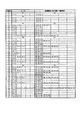
図11は、式(2)を満たす、中継電極の電極数Xが2から50の場合の送信電極,検出電極,中継電極の組み合わせを示す表である。例えば、中継電極の電極数Xが5の場合、n=1,m=1で式(2)を満たし、図4に示すような4極の送信電極、4極の検出電極、及び、5極の中継電極からなる静電エンコーダを実現することができる。また中継電極の電極数Xが10の場合、n=2,m=1で式(2)を満たし、図7に示すような8極の送信電極、8極の検出電極、及び、10極の中継電極からなる静電エンコーダを実現することができる。   FIG. 11 is a table showing combinations of transmission electrodes, detection electrodes, and relay electrodes when the number of relay electrodes X is 2 to 50, satisfying the formula (2). For example, when the number X of relay electrodes is 5, n = 1, m = 1 and the formula (2) is satisfied, and a 4-pole transmission electrode, 4-pole detection electrode, and 5-pole as shown in FIG. It is possible to realize an electrostatic encoder comprising the relay electrodes. Further, when the number X of relay electrodes is 10, n = 2, m = 1 and the formula (2) is satisfied, and an 8-pole transmission electrode, an 8-pole detection electrode, and a 10-pole electrode as shown in FIG. An electrostatic encoder composed of a relay electrode can be realized.

上述した静電エンコーダは、固定子及び回転子の円周方向に1層の電極を配置するが、これらの電極を中心から外周に向かって2層に配置する固定子及び回転子であってもよい。図12は、第3の実施例に係る静電エンコーダ120を示す。静電エンコーダ120は、固定子及び回転子の円周方向の外層及び内層の2層に電極を配置する。すなわち、固定子12は、4極の送信電極及び4極の検出電極を帯状の外層及び内層面のそれぞれに等間隔で配置する。また、回転子122は、4極の中継電極を帯状の外層及び内層面のそれぞれに等間隔で配置する。 In the electrostatic encoder described above, one layer of electrodes is arranged in the circumferential direction of the stator and the rotor, but these electrodes may be arranged in two layers from the center toward the outer circumference. Good. FIG. 12 shows an electrostatic encoder 120 according to the third embodiment. The electrostatic encoder 120 arranges electrodes on two layers of an outer layer and an inner layer in the circumferential direction of the stator and the rotor. That is, the stator 12 1 places the detection electrodes of the transmitter electrode and four-pole four-pole at equal intervals in each of the band-shaped outer layer and the inner layer surface. Moreover, the rotor 122 arrange | positions a 4 pole relay electrode at equal intervals on each of a strip | belt-shaped outer layer and inner layer surface.

図12に示される静電エンコーダ120は、外層に検出電極124a〜124d及び送信電極125a〜125dを交互に配置し、かつ内層に検出電極124e〜124h及び送信電極125e〜125hを交互に配置する固定子121、及び、外層及び内層にそれぞれ4極の中継電極127a〜127hを配置する回転子122を具備する。固定子121の外層に配置される検出電極124a〜124d及び送信電極125a〜125dと内層に配置される検出電極124e〜124h及び送信電極125e〜125hは、相互に回転角で22.5°ずれている。その結果、図6(1)の検出原理で説明されたとおり、外層がA相及び/A相の検出信号を導く系統(A相系統)を形成すると共に、内層がB相及び/B相の検出信号を導く系統(B相系統)を形成する。A相及び/A相の検出信号及びB相及び/B相の検出信号は、差動演算増幅器129a,129bにそれぞれ入力され、演算増幅器129a,129bは、回転子122の回転に伴って振幅変調される出力信号Va,Vbを出力する。出力信号Va,Vbは復調されて、変調信号V1,V2を出力し、それらは相互に90°の位相差を有する。これらの変調信号V1,V2から、回転子122の回転角が求められる。   The electrostatic encoder 120 shown in FIG. 12 is fixed in which detection electrodes 124a to 124d and transmission electrodes 125a to 125d are alternately arranged on the outer layer, and detection electrodes 124e to 124h and transmission electrodes 125e to 125h are alternately arranged on the inner layer. And a rotor 122 in which relay electrodes 127a to 127h having four poles are arranged on the outer layer and the inner layer, respectively. The detection electrodes 124a to 124d and the transmission electrodes 125a to 125d arranged in the outer layer of the stator 121 and the detection electrodes 124e to 124h and the transmission electrodes 125e to 125h arranged in the inner layer are shifted from each other by 22.5 ° in rotation angle. Yes. As a result, as explained in the detection principle of FIG. 6 (1), the outer layer forms a system (A phase system) that leads the detection signals of the A phase and the / A phase, and the inner layer has the B phase and the / B phase. A system (B-phase system) for guiding the detection signal is formed. The A-phase and / A-phase detection signals and the B-phase and / B-phase detection signals are input to the differential operational amplifiers 129a and 129b, respectively. The operational amplifiers 129a and 129b perform amplitude modulation as the rotor 122 rotates. Output signals Va and Vb are output. The output signals Va and Vb are demodulated to output modulated signals V1 and V2, which have a phase difference of 90 ° from each other. From these modulation signals V1, V2, the rotation angle of the rotor 122 is obtained.

次に、図12に示される静電エンコーダ120が相互に90°の位相差を有する変調信号V1,V2を出力することを以下検討する。図13(a)は、固定子121の外層に配置された検出電極124a〜124d及び送信電極125a〜125dと回転子122の外層に配置された中継電極127a〜127dとの間の、回転子122の回転による相対的な位置関係を示す。図13(b)は、回転子122の回転による電極間の対向面積の変化、及び、その対向面積の変化に基づく差動出力(A相系統)の変化を表す波形図を示す。固定子上の送信電極及び検出電極、及び、回転子上の中継電極は、回転子及び固定子上を円周状に配置されるが、図13(a)は、対向関係を明確にするために直線上に描く。   Next, it will be examined below that the electrostatic encoder 120 shown in FIG. 12 outputs the modulation signals V1 and V2 having a phase difference of 90 ° from each other. FIG. 13A shows the rotor 122 between the detection electrodes 124a to 124d and transmission electrodes 125a to 125d arranged in the outer layer of the stator 121 and the relay electrodes 127a to 127d arranged in the outer layer of the rotor 122. The relative positional relationship by rotation of is shown. FIG. 13B is a waveform diagram showing a change in the facing area between the electrodes due to the rotation of the rotor 122 and a change in the differential output (A phase system) based on the change in the facing area. The transmission electrode and detection electrode on the stator and the relay electrode on the rotor are circumferentially arranged on the rotor and the stator, but FIG. 13A is for clarifying the facing relationship. Draw on a straight line.

まず、固定子120の外層に配置された検出電極124a〜124d及び送信電極125a〜125dと回転子122の外層に配置された中継電極127a〜127dとの間の対向面積の変化について検討する。図13(a)及び図13(b)(1)を参照して、例えば、回転子122が回転角0°であるとき、送信電極125aは、中継電極127aと完全に対向し(最大の対向面積)、その状態を回転角45°まで継続する。その後、中継電極127aに対する対向面積は減少し、回転角67.5°でゼロに達する。回転角67.5°で中継電極127aに対する対向面積がゼロに達すると同時に、中継電極127dは、送信電極125aと対向関係を開始し、送信電極125aに対する対向面積は回転角90°で完全に対向する。その後、図13(b)(1)に示されるように、送信電極125aと中継電極との間の対向面積は、同じ波形が繰り返される。なお、図13(a)に示されるように、送信電極125b,125c,125dの中継電極127b,127c,127dに対する対向関係は、送信電極125aの中継電極127aに対する対向関係とそれぞれ同じ関係であるので、送信電極125b,125c,125dと中継電極との間の対向面積の変化は、図12(b)(1),(2)に示される波形と同じ波形となる。 First, the change in the facing area between the detection electrodes 124a to 124d and transmission electrodes 125a to 125d arranged in the outer layer of the stator 120 and the relay electrodes 127a to 127d arranged in the outer layer of the rotor 122 will be examined. 13 (a) and 13 (b) (1), for example, when the rotor 122 has a rotation angle of 0 °, the transmission electrode 125a completely faces the relay electrode 127a (maximum facing). Area), and the state is continued up to a rotation angle of 45 °. Thereafter, the area facing the relay electrode 127a decreases and reaches zero at a rotation angle of 67.5 °. At the same time as the counter area with respect to the relay electrode 127a reaches zero at a rotation angle of 67.5 °, the relay electrode 127d starts a counter relationship with the transmission electrode 125a, and the counter area with respect to the transmission electrode 125a is completely opposite at a rotation angle of 90 °. To do. Thereafter, as shown in FIGS. 13B and 13A, the same waveform is repeated in the facing area between the transmission electrode 125a and the relay electrode. Incidentally, as shown in FIG. 13 (a), the transmitting electrodes 125b, 125c, 125d of the relay electrodes 127b, 127c, opposed relationship to 127d is because it is opposed relationship with each same relationship to the relay electrode 127a of the transmitting electrode 125a The change in the facing area between the transmission electrodes 125b, 125c, 125d and the relay electrode is the same as the waveforms shown in FIGS. 12 (b), (1), and (2).

次に、送信電極に対向する中継電極と検出電極との間の対向面積の変化を検討する。図13(a)に示されるように、回転子122の回転角が0°のとき、送信電極125aに対向する中継電極は、中継電極127aである。従って、検出電極124aは中継電極127aを介して送信電極125aからの高周波信号を受信するので、中継電極127aと検出電極124aとの間の対向面積の変化を求める。図13(a)に示されるように、回転子122の回転角が0°のとき、検出電極124aの全面が中継電極127aと対向関係にある。従って、図13(b)(3)に示されるように、対向面積は回転角0°で最大を示す。回転子122の回転が進行すると、中継電極127aは図13(a)において右へ移動するため、中継電極127aと検出電極124aとの間の対向面積は減少に転じる。回転子122の回転角が22.5°に達すると、中継電極127aと検出電極124aとの間の対向関係はなくなり、対向面積はゼロとなる。その後、送信電極125aに対向する中継電極が検出電極124aに対向する状態はなく、対向面積はゼロを維持する。回転子122が回転角67.5°に達すると、中継電極127dが送信電極125aと対向関係を開始する。回転角67.5°で中継電極127dは検出電極124aの全面と対向しているので、中継電極127dと検出電極124aとの間の対向面積は一気に最大値を示すことになる。そして、回転子122が回転角90°になるまで、最大の対向面積が維持される。その後、図13(b)(3)に示されるように、検出電極124aは、後続する中継電極(127c,127b,・・・)との間で対向関係を持ち、それらの間の対向面積は、中継電極127aと検出電極124aとの間の対向面積の変化と同じ変化を繰り返す。なお、図13(a)に示されるように、検出電極124cの中継電極127cに対する対向関係は、検出電極124aの中継電極127aに対する対向関係と同じ関係であるので、検出電極12cと中継電極(127c,127b,・・・)との間の対向面積の変化は、図13(b)(3)に示される波形と同じ波形である。 Next, a change in the facing area between the relay electrode and the detection electrode facing the transmission electrode will be considered. As shown in FIG. 13A, when the rotation angle of the rotor 122 is 0 °, the relay electrode facing the transmission electrode 125a is the relay electrode 127a. Therefore, since the detection electrode 124a receives the high frequency signal from the transmission electrode 125a via the relay electrode 127a, the change in the facing area between the relay electrode 127a and the detection electrode 124a is obtained. As shown in FIG. 13A, when the rotation angle of the rotor 122 is 0 °, the entire surface of the detection electrode 124a is opposed to the relay electrode 127a. Therefore, as shown in FIGS. 13B and 13C, the facing area shows the maximum at a rotation angle of 0 °. As the rotation of the rotor 122 proceeds, the relay electrode 127a moves to the right in FIG. 13A, and the facing area between the relay electrode 127a and the detection electrode 124a starts to decrease. When the rotation angle of the rotor 122 reaches 22.5 °, the facing relationship between the relay electrode 127a and the detection electrode 124a disappears, and the facing area becomes zero. Thereafter, there is no state in which the relay electrode facing the transmission electrode 125a faces the detection electrode 124a, and the facing area is maintained at zero. When the rotor 122 reaches a rotation angle of 67.5 °, the relay electrode 127d starts to face the transmission electrode 125a. Since the relay electrode 127d is opposed to the entire surface of the detection electrode 124a at a rotation angle of 67.5 °, the facing area between the relay electrode 127d and the detection electrode 124a immediately exhibits the maximum value. The maximum facing area is maintained until the rotor 122 has a rotation angle of 90 °. Thereafter, as shown in FIGS. 13B and 13C, the detection electrode 124a has a facing relationship with the subsequent relay electrodes (127c, 127b,...), And the facing area between them is as follows. The same change as the change in the facing area between the relay electrode 127a and the detection electrode 124a is repeated. Incidentally, as shown in FIG. 13 (a), facing relation with respect to the relay electrode 127c of the detection electrode 124c is because it is the same relationship as opposed relationship with respect to the relay electrode 127a of the detecting electrodes 124a, the detection electrodes 12 4 c and the relay electrode The change in the facing area between (127c, 127b,...) Is the same waveform as the waveforms shown in FIGS.

上述と同様の手順に従って他の電極間の対向面積の変化を検討すると、図13(b)(4)に、送信電極125bに対向している中継電極と検出電極124cとの間の対向面積の変化、及び、送信電極125dに対向している中継電極と検出電極124aとの間の対向面積の変化が示される。また、図12(b)(5)に、送信電極125aに対向している中継電極と検出電極124bとの間の対向面積の変化、及び、送信電極125cに対向している中継電極と検出電極124dとの間の対向面積の変化が示される。さらに、図12(b)(6)に、送信電極125bに対向している中継電極と検出電極124bとの間の対向面積の変化、及び、送信電極125dに対向している中継電極と検出電極124dとの間の対向面積の変化が示される。 Examining the change in the facing area between the other electrodes according to the same procedure as described above, FIGS. 13B and 13B show the facing area between the relay electrode facing the transmitting electrode 125b and the detecting electrode 124c. The change and the change in the facing area between the relay electrode facing the transmission electrode 125d and the detection electrode 124a are shown. Further, in FIG. 12 (b) (5), a change in facing area between the relay electrode and the detection electrode 124b facing the transmission electrodes 125a, and the relay electrode and the detection electrode facing the transmission electrode 125c The change of the facing area between 124d is shown. Further, in FIG. 12 (b) (6), a change in facing area between the relay electrode and the detection electrode 124b facing the transmitting electrodes 125b, and the relay electrode and the detection electrode facing the transmission electrodes 125d The change of the facing area between 124d is shown.

以上により、送信電極と中継電極との間の対向面積の変化、及び、中継電極と検出電極との間の対向面積の変化がそれぞれ示された。これらの対向面積の変化から、外層に配置された検出電極からみた、回転子の回転による送信電極に対する対向面積の変化を検討する。   As described above, the change in the facing area between the transmission electrode and the relay electrode and the change in the facing area between the relay electrode and the detection electrode are shown. Based on the change in the facing area, the change in the facing area with respect to the transmission electrode due to the rotation of the rotor as viewed from the detection electrode arranged in the outer layer will be examined.

まず、検出電極124aは、送信電極125aから中継電極を経由して伝送される高調波信号(Vsinωt)、及び、送信電極125dから中継電極を経由して伝送される反転高調波信号(−Vsinωt)を受信する。検出電極124aで受信する高調波信号は、送信電極125aとその送信電極125aに対向する中継電極との間の静電容量及びその中継電極と検出電極124aとの間の静電容量に応じて、振幅変調を受ける。また、検出電極124aで受信する反転高調波信号は、送信電極125dとその送信電極125dに対向する中継電極との間の静電容量及びその中継電極と検出電極124aとの間の静電容量に応じて、振幅変調を受ける。従って、この静電容量は対向面積に対応すると考えられるから、検出電極124aで受信する検出信号は、検出電極124aが高調波信号を受信する期間、送信電極125aと中継電極との間の対向面積(図13(b)(1))に、送信電極125aに対向する中継電極と検出電極124aとの間の対向面積(図13(b)(3))を乗じた値で振幅変調され、また、検出電極124aが反転高調波信号を受信する期間、送信電極125dと中継電極との間の対向面積(図13(b)(2))に、送信電極125dに対向する中継電極と検出電極124aとの間の対向面積(図13(b)(4))を乗じた値で振幅変調される。すなわち、検出電極124aで検出される検出信号は、図13(b)(7)で示される三角波の振幅変調を受ける。なお、検出電極124cは、検出電極124aと同じ信号を生成するので、検出電極124aと検出電極124cは結合され、A相の検出信号として差動演算増幅器129aに入力される。 First, the detection electrode 124a has a harmonic signal (Vsinωt) transmitted from the transmission electrode 125a via the relay electrode and an inverted harmonic signal (−Vsinωt) transmitted from the transmission electrode 125d via the relay electrode. Receive. The harmonic signal received by the detection electrode 124a depends on the capacitance between the transmission electrode 125a and the relay electrode facing the transmission electrode 125a and the capacitance between the relay electrode and the detection electrode 124a. Receives amplitude modulation. Further, the inverted harmonic signal received by the detection electrode 124a has a capacitance between the transmission electrode 125d and the relay electrode facing the transmission electrode 125d and a capacitance between the relay electrode and the detection electrode 124a. In response, it undergoes amplitude modulation. Therefore, since this electrostatic capacity is considered to correspond to the opposing area, the detection signal received by the detection electrode 124a is the opposing area between the transmission electrode 125a and the relay electrode during the period in which the detection electrode 124a receives the harmonic signal. (FIG. 13 (b) (1)) is amplitude-modulated by a value obtained by multiplying the facing area (FIG. 13 (b) (3)) between the relay electrode facing the transmission electrode 125a and the detection electrode 124a. During the period in which the detection electrode 124a receives the inverted harmonic signal, the relay electrode and the detection electrode 124a facing the transmission electrode 125d are placed in the opposing area between the transmission electrode 125d and the relay electrode (FIGS. 13B and 2). Amplitude modulation is performed by a value obtained by multiplying the facing area (FIGS. 13 (b) and (4)). That is, the detection signal detected by the detection electrode 124a is subjected to the amplitude modulation of the triangular wave shown in FIGS. Since the detection electrode 124c generates the same signal as the detection electrode 124a, the detection electrode 124a and the detection electrode 124c are combined and input to the differential operational amplifier 129a as an A-phase detection signal.

上述と同様に、検出電極124bで検出される/A相の検出信号は、図13(b)(8)で示される三角波の振幅変調を受ける。図13(b)(8)で示される三角波は、図13(b)(7)で示される三角波を反転した三角波に等しいので、/A相の検出信号は、より大きな出力信号Vaを得るため、差動演算増幅器129aでA相の検出信号と差動増幅される。   Similarly to the above, the detection signal of the / A phase detected by the detection electrode 124b is subjected to triangular wave amplitude modulation shown in FIGS. Since the triangular wave shown in FIGS. 13 (b) and (8) is equal to the triangular wave obtained by inverting the triangular wave shown in FIGS. 13 (b) and (7), the / A phase detection signal is used to obtain a larger output signal Va. The differential operational amplifier 129a performs differential amplification with the A-phase detection signal.

次に、固定子120の内層に配置された検出電極124e〜124h及び送信電極125e〜124hと回転子122の内層に配置された中継電極127e〜127hとの間の対向面積の変化は、外層に配置された電極間の対向面積の変化と同様の手法により求められる。図14(a)は、内層に配置された電極間の、回転子の回転による相対的な位置関係を、図14(b)は、回転子の回転による内層に配置された電極間の対向面積の変化、及び、その対向面積の変化に基づく差動出力(B相系統)の変化を表す波形図を示す。図14(b)(1)は、送信電極125e(送信電極125g)と中継電極との間の対向面積の変化を、図14(b)(2)は、送信電極125f(送信電極125h)と中継電極との間の対向面積の変化を示す。また、図14(b)(3)〜(6)は、送信電極とその送信電極と対向している中継電極との間の対向面積の変化を示す。 Next, the change in the facing area between the detection electrodes 124e to 124h and the transmission electrodes 125e to 124h arranged in the inner layer of the stator 120 and the relay electrodes 127e to 127h arranged in the inner layer of the rotor 122 is changed to the outer layer. It is calculated | required by the method similar to the change of the opposing area between the arrange | positioned electrodes. 14A shows the relative positional relationship between the electrodes arranged in the inner layer due to the rotation of the rotor, and FIG. 14B shows the facing area between the electrodes arranged in the inner layer due to the rotation of the rotor. The waveform diagram showing the change of the differential output (B phase system) based on the change of this and the change of the opposing area is shown. 14 (b) and (1) show changes in the facing area between the transmission electrode 125e (transmission electrode 125g) and the relay electrode, and FIGS. 14 (b) and (2) show the transmission electrode 125f (transmission electrode 125h). The change of the opposing area between relay electrodes is shown. Moreover, FIG.14 (b) (3)-(6) shows the change of the opposing area between a transmission electrode and the relay electrode facing the transmission electrode.

さらに、検出電極aが検出する検出信号と同様に、検出電極124eで検出する検出信号は、送信電極125eからの高調波信号と送信電極125hからの反転高調波信号が重なった信号である。その高調波信号は、送信電極125eと送信電極125eに対向する中継電極との間の静電容量により振幅変調され、次にその中継電極と検出電極124eとの間の静電容量により振幅変調される。従って、検出電極124eで検出する検出信号は、送信電極125eと中継電極との間の対向面積(図14(b)(1))に、送信電極125eに対向する中継電極と検出電極124eとの間の対向面積(図14(b)(3))を乗じた値で振幅変調され、また、反転高調波信号は、送信電極125hと送信電極125hに対向する中継電極との間の対向面積(図14(b)(2))に、その中継電極と検出電極124eとの間の対向面積(図14(b)(4))を乗じた値で振幅変調される。すなわち、検出電極124eからみた送信電極125e,125hに対する対向面積の変化は、図14(b)(7)で示される三角波となり、その結果検出電極124eで検出される検出信号は、図14(b)(7)で示される三角波の振幅変調を受ける。なお、検出電極124gは、検出電極124aと同じ信号を生成するので、検出電極124aと検出電極124gは結合され、B相の検出信号として差動演算増幅器129bに入力される。検出電極124fからみた送信電極125e,125fに対する対向面積の変化も同様に、図14(b)(8)で示される三角波となり、その結果検出電極124fで検出される検出信号は、図14(b)(8)で示される三角波の振幅変調を受ける。なお、検出電極124hは、検出電極124fと同じ信号を生成するので、検出電極124eと検出電極124hは結合され、/B相の検出信号として差動演算増幅器129bに入力される。 Further, similarly to the detection signal detected by the detection electrode a, the detection signal detected by the detection electrode 124e is a signal in which the harmonic signal from the transmission electrode 125e and the inverted harmonic signal from the transmission electrode 125h overlap. The harmonic signal is amplitude-modulated by the capacitance between the transmission electrode 125e and the relay electrode facing the transmission electrode 125e, and then amplitude-modulated by the capacitance between the relay electrode and the detection electrode 124e. The Therefore, the detection signal detected by the detection electrode 124e is in the opposite area (FIGS. 14B and 1) between the transmission electrode 125e and the relay electrode, between the relay electrode facing the transmission electrode 125e and the detection electrode 124e. The amplitude modulation is performed by a value obtained by multiplying the facing area (FIGS. 14 (b) and (3)) between the transmitting electrode 125h and the relay electrode facing the transmitting electrode 125h. 14 (b) (2)) is amplitude-modulated by a value obtained by multiplying the opposing area (FIGS. 14 (b) (4)) between the relay electrode and the detection electrode 124e. That is, the change in the area facing the transmission electrodes 125e and 125h as seen from the detection electrode 124e becomes a triangular wave shown in FIGS. 14B and 14B, and as a result, the detection signal detected by the detection electrode 124e is as shown in FIG. ) Undergoes amplitude modulation of the triangular wave shown in (7). Since the detection electrode 124g generates the same signal as the detection electrode 124a, the detection electrode 124a and the detection electrode 124g are combined and input to the differential operational amplifier 129b as a B-phase detection signal. Similarly, the change in the facing area with respect to the transmission electrodes 125e and 125f as seen from the detection electrode 124f is also a triangular wave shown in FIGS. 14B and 8F, and the detection signal detected by the detection electrode 124f as a result is shown in FIG. ) Undergoes amplitude modulation of the triangular wave shown in (8). Since the detection electrode 124h generates the same signal as the detection electrode 124f, the detection electrode 124e and the detection electrode 124h are combined and input to the differential operational amplifier 129b as a / B phase detection signal.

なお、電極間の静電容量は、実際には電極が正対(直角方向に対向)する面積だけで形成されるのではなく、斜め方向にも、電極間の距離に応じて形成されるため、狭い電極間の間隔を有する回転子が移動するとき、電極間の実際の静電容量の変化は、三角波ではなく、正弦波に近くなる。従って、演算増幅器129a,129bから出力される出力信号Va,Vbの電圧も正弦波の振幅変調を受けた信号波形を示す。 In addition, the capacitance between the electrodes is actually formed not only in the area where the electrodes face each other ( opposite in the perpendicular direction) but also in the oblique direction according to the distance between the electrodes. When a rotor with a narrow inter-electrode spacing moves, the actual capacitance change between the electrodes is close to a sine wave rather than a triangular wave. Therefore, the voltages of the output signals Va and Vb output from the operational amplifiers 129a and 129b also show signal waveforms that have undergone sinusoidal amplitude modulation.

演算増幅器129a,129bから出力される出力信号Va,Vbは、図示しない復調器により復調され、その復調器は、図15に示される変調信号V1,V2を出力する。変調信号V1,V2は、相対的に90°の位相差を有するため、変調信号V1,V2に対して周知のレゾルバデジタル(RD)変換処理を適用して、回転子122の回転角を求めることができる。回転子122が外層及び内層に4極の中継電極127a〜127d,127e〜127hを配置しているので、回転子122が1回転(360°)すると、図13,14に示されるように、静電エンコーダ121は、4周期の正弦波を出力する。このように、本発明に係る静電エンコーダは、図12に示されるように、送信電極と検出電極を回転方向に交互に配置する固定子、及び、その固定子に近接して配置される回転子からなり、その回転子の回転角は、その回転子の回転により出力される90°の位相差を有する正弦波の変調信号から求めることができる。   Output signals Va and Vb output from the operational amplifiers 129a and 129b are demodulated by a demodulator (not shown), and the demodulator outputs modulated signals V1 and V2 shown in FIG. Since the modulation signals V1 and V2 have a relative phase difference of 90 °, a known resolver digital (RD) conversion process is applied to the modulation signals V1 and V2 to obtain the rotation angle of the rotor 122. Can do. Since the rotor 122 has the four-pole relay electrodes 127a to 127d and 127e to 127h arranged on the outer layer and the inner layer, when the rotor 122 makes one rotation (360 °), as shown in FIGS. The electric encoder 121 outputs a four-cycle sine wave. Thus, as shown in FIG. 12, the electrostatic encoder according to the present invention includes a stator in which the transmission electrodes and the detection electrodes are alternately arranged in the rotation direction, and a rotation arranged in the vicinity of the stator. The rotation angle of the rotor can be obtained from a sinusoidal modulation signal having a phase difference of 90 ° output by the rotation of the rotor.

以上の説明により、本発明にかかる静電エンコーダの固定子は、送信電極と検出電極を回転方向に交互に配置するため、中継電極を配置する回転子の回転により、検出電極で検出される検出信号から位相差を有する正弦波の変調信号を得ることができる。位相差を有する正弦波の変調信号から回転子の回転角を求めることができる。また、上述する実施例の静電エンコーダは、固定子及び回転子からなっているが、敢えて固定子及び回転子を用意しなくても、2つの要素があれば、その一方の要素上の回転方向に交互に送信電極と検出電極を配置し、他方の要素上に中継電極を配置する構造を形成して、その2つの要素の相対的な回転角を求めるようにしてもよい。さらに、送信電極、検出電極、及び中継電極を直線上に配置して、直線方向の移動量を求めることもできる。   As described above, since the stator of the electrostatic encoder according to the present invention alternately arranges the transmission electrode and the detection electrode in the rotation direction, the detection detected by the detection electrode by the rotation of the rotor where the relay electrode is arranged. A sinusoidal modulation signal having a phase difference can be obtained from the signal. The rotation angle of the rotor can be obtained from a sine wave modulation signal having a phase difference. In addition, the electrostatic encoder of the above-described embodiment includes a stator and a rotor. However, if there are two elements without preparing the stator and the rotor, the rotation on one element is possible. It is also possible to form a structure in which transmission electrodes and detection electrodes are alternately arranged in the direction and a relay electrode is arranged on the other element, and the relative rotation angle between the two elements may be obtained. Further, the transmission electrode, the detection electrode, and the relay electrode can be arranged on a straight line, and the amount of movement in the linear direction can be obtained.

40,70,120 静電エンコーダ
41,71,121 固定子
42,72,122 回転子
44a〜44d,74a〜74h,124a〜124h 検出電極
45a〜45d,75a〜75h,125a〜125h 送信電極
47a〜47e,77a〜77j,127a〜127h 中継電極
48a,78a,128a 高周波信号
48b,78b,128b 反転高周波信号
49,79a〜79b,129a〜129b 差動演算増幅器
Va,Vb 出力信号
V1,V2 変調信号
40, 70, 120 Electrostatic encoder 41, 71, 121 Stator 42, 72, 122 Rotor 44a-44d, 74a-74h, 124a-124h Detection electrode 45a-45d, 75a-75h, 125a-125h Transmission electrode 47a- 47e, 77a-77j, 127a-127h Relay electrodes 48a, 78a, 128a High-frequency signals 48b, 78b, 128b Inverted high-frequency signals 49, 79a-79b, 129a-129b Differential operational amplifiers Va, Vb Output signals V1, V2 Modulation signals

Claims (12)

第1及び第2絶縁部材の相対向する表面上に配置される電極により形成される静電容量を用いて、前記第1絶縁部材の測定方向の変位を計測する静電エンコーダにおいて、前記電極は、
前記第1絶縁部材に予め定める第1電極周期で前記測定方向に等間隔で配置される複数の中継電極と、
前記第2絶縁部材に予め定める第2電極周期で前記測定方向に等間隔で配置される複数の送信電極及び検出電極であって、前記複数の送信電極及び前記検出電極は、前記測定方向に交互に配置される、複数の送信電極及び検出電極と、
から構成されることを特徴とする静電エンコーダ。
In the electrostatic encoder that measures the displacement in the measurement direction of the first insulating member using the electrostatic capacitance formed by the electrodes disposed on the opposing surfaces of the first and second insulating members, the electrode includes: ,
A plurality of relay electrodes arranged at equal intervals in the measurement direction at a predetermined first electrode period on the first insulating member;
A plurality of transmission electrodes and detection electrodes arranged at equal intervals in the measurement direction at a predetermined second electrode period on the second insulating member, wherein the plurality of transmission electrodes and detection electrodes are alternately arranged in the measurement direction; A plurality of transmission electrodes and detection electrodes,
An electrostatic encoder comprising:
前記第1絶縁部材は円板状の固定子であり、かつ前記第2絶縁部材は円板状の回転子であることを特徴とする請求項1記載の静電エンコーダ。   The electrostatic encoder according to claim 1, wherein the first insulating member is a disk-shaped stator, and the second insulating member is a disk-shaped rotor. 前記第2電極周期は、前記第1電極周期とは異なる予め定める電極周期に設定され、前記複数の送信電極に高周波信号及び前記高周波信号を反転した反転高周波信号を前記円周方向に交互に与えると、隣接する前記検出電極間で検出される検出信号が90°の位相差を有することを特徴とする請求項2記載の静電エンコーダ。   The second electrode period is set to a predetermined electrode period different from the first electrode period, and a high-frequency signal and an inverted high-frequency signal obtained by inverting the high-frequency signal are alternately applied to the plurality of transmission electrodes in the circumferential direction. The electrostatic encoder according to claim 2, wherein a detection signal detected between the adjacent detection electrodes has a phase difference of 90 °. 前記検出電極で検出される90°の位相差を有する検出信号に基づいて、前記回転子の回転角を求めることを特徴とする請求項3記載の静電エンコーダ。   The electrostatic encoder according to claim 3, wherein the rotation angle of the rotor is obtained based on a detection signal having a phase difference of 90 ° detected by the detection electrode. 前記複数の中継電極は、前記回転子の中心から放射状に広がる略台形の形状であり、かつ前記送信電極及び前記検出電極は、前記固定子の中心から放射状に広がる略台形の形状であることを特徴とする請求項2記載の静電エンコーダ。   The plurality of relay electrodes have a substantially trapezoidal shape extending radially from the center of the rotor, and the transmission electrode and the detection electrode have a substantially trapezoidal shape extending radially from the center of the stator. The electrostatic encoder according to claim 2, wherein: 前記固定子に4nm個の前記送信電極及び前記検出電極をそれぞれ配置し、かつ前記回転子にX個の前記中継電極を配置する場合、
X/4n=m±0.25
の関係を満たし、
n及びmは、1以上の自然数である、
ことを特徴とする請求項2記載の静電エンコーダ。
In the case where 4 nm of the transmission electrode and the detection electrode are respectively arranged on the stator, and X pieces of the relay electrodes are arranged on the rotor,
X / 4n = m ± 0.25
Satisfy the relationship
n and m are natural numbers of 1 or more,
The electrostatic encoder according to claim 2.
前記検出電極の内の第1の検出電極で検出された検出信号と前記第1の検出電極から円周方向にm個離れた第2の検出電極で検出された検出信号とに基づいて、前記回転子の回転角を求めることを特徴とする請求項6記載の静電エンコーダ。   Based on a detection signal detected by a first detection electrode of the detection electrodes and a detection signal detected by a second detection electrode which is m circumferentially separated from the first detection electrode, The electrostatic encoder according to claim 6, wherein a rotation angle of the rotor is obtained. 円板状の回転子及び固定子の相対向する表面上に配置される電極により形成される静電容量を用いて前記回転子の回転角を計測する静電エンコーダにおいて、前記電極は、
前記回転子の円周方向に形成される外層及び内層のそれぞれに前記円周方向に等間隔で配置される複数の中継電極と、
前記固定子の円周方向に形成される外層及び内層のそれぞれに前記円周方向に等間隔で配置される複数の送信電極及び検出電極であって、前記複数の送信電極及び前記検出電極は、前記円周方向に交互に配置される、複数の送信電極及び検出電極と、
から構成されることを特徴とする静電エンコーダ。
In the electrostatic encoder that measures the rotation angle of the rotor using the electrostatic capacitance formed by the electrodes disposed on the opposing surfaces of the disk-shaped rotor and the stator, the electrode includes:
A plurality of relay electrodes arranged at equal intervals in the circumferential direction on each of an outer layer and an inner layer formed in the circumferential direction of the rotor;
A plurality of transmission electrodes and detection electrodes arranged at equal intervals in the circumferential direction on each of an outer layer and an inner layer formed in the circumferential direction of the stator, wherein the plurality of transmission electrodes and the detection electrodes are A plurality of transmission electrodes and detection electrodes alternately arranged in the circumferential direction;
An electrostatic encoder comprising:
前記固定子の外層に配置される前記複数の送信電極及び検出電極は、前記回転子の外層に配置される前記複数の中継電極と同一の電極周期で配置され、かつ前記固定子の内層に配置される前記複数の送信電極及び検出電極は、前記回転子の内層に配置される前記複数の中継電極と同一の電極周期で配置されることを特徴とする請求項8記載の静電エンコーダ。   The plurality of transmission electrodes and detection electrodes arranged in the outer layer of the stator are arranged in the same electrode cycle as the plurality of relay electrodes arranged in the outer layer of the rotor, and arranged in the inner layer of the stator The electrostatic encoder according to claim 8, wherein the plurality of transmission electrodes and detection electrodes that are arranged are arranged at the same electrode period as the plurality of relay electrodes arranged in an inner layer of the rotor. 前記固定子の内層に配置される前記複数の送信電極及び検出電極は、前記固定子の外層に配置される前記複数の送信電極及び検出電極に対して円周方向の予め定める角度だけずれて配置されることを特徴とする請求項8記載の静電エンコーダ。   The plurality of transmission electrodes and detection electrodes arranged in the inner layer of the stator are arranged so as to be shifted by a predetermined angle in the circumferential direction with respect to the plurality of transmission electrodes and detection electrodes arranged in the outer layer of the stator. The electrostatic encoder according to claim 8, wherein the electrostatic encoder is used. 前記複数の送信電極に高周波信号及び前記高周波信号を反転した反転高周波信号を前記円周方向に交互に与えると、前記外層の前記検出電極と前記内層の前記検出電極と間で90°の位相差を有する検出信号が検出されることを特徴とする請求項8記載の静電エンコーダ。   When a high-frequency signal and an inverted high-frequency signal obtained by inverting the high-frequency signal are alternately applied to the plurality of transmission electrodes in the circumferential direction, a phase difference of 90 ° between the detection electrode on the outer layer and the detection electrode on the inner layer The electrostatic encoder according to claim 8, wherein a detection signal having the following is detected. 前記外層の検出電極及び前記内層の検出電極で検出される90°の位相差を有する検出信号に基づいて、前記回転子の回転角を求めることを特徴とする請求項11記載の静電エンコーダ。   The electrostatic encoder according to claim 11, wherein a rotation angle of the rotor is obtained based on a detection signal having a phase difference of 90 ° detected by the detection electrode of the outer layer and the detection electrode of the inner layer.
JP2014255350A 2014-12-17 2014-12-17 Electrostatic encoder Active JP6156747B2 (en)

Priority Applications (9)

Application Number Priority Date Filing Date Title
JP2014255350A JP6156747B2 (en) 2014-12-17 2014-12-17 Electrostatic encoder
PCT/JP2015/084130 WO2016098613A1 (en) 2014-12-17 2015-12-04 Electrostatic encoder
US15/536,357 US10551219B2 (en) 2014-12-17 2015-12-04 Electrostatic encoder
EP15869818.3A EP3236214B1 (en) 2014-12-17 2015-12-04 Electrostatic encoder
KR1020177019622A KR101957957B1 (en) 2014-12-17 2015-12-04 Electrostatic encoder
EP18212505.4A EP3486614B1 (en) 2014-12-17 2015-12-04 Electrostatic encoder
CN201580068399.XA CN107003154B (en) 2014-12-17 2015-12-04 Electrostatic encoder
TW104142073A TWI681172B (en) 2014-12-17 2015-12-15 Electrostatic encoder
TW108130267A TWI699515B (en) 2014-12-17 2015-12-15 Electrostatic encoder

Applications Claiming Priority (1)

Application Number Priority Date Filing Date Title
JP2014255350A JP6156747B2 (en) 2014-12-17 2014-12-17 Electrostatic encoder

Publications (3)

Publication Number Publication Date
JP2016114559A JP2016114559A (en) 2016-06-23
JP2016114559A5 JP2016114559A5 (en) 2016-09-01
JP6156747B2 true JP6156747B2 (en) 2017-07-05

Family

ID=56126506

Family Applications (1)

Application Number Title Priority Date Filing Date
JP2014255350A Active JP6156747B2 (en) 2014-12-17 2014-12-17 Electrostatic encoder

Country Status (7)

Country Link
US (1) US10551219B2 (en)
EP (2) EP3236214B1 (en)
JP (1) JP6156747B2 (en)
KR (1) KR101957957B1 (en)
CN (1) CN107003154B (en)
TW (2) TWI681172B (en)
WO (1) WO2016098613A1 (en)

Families Citing this family (4)

* Cited by examiner, † Cited by third party
Publication number Priority date Publication date Assignee Title
DE102017126271A1 (en) * 2017-11-09 2019-05-09 Webasto SE Positioning of motors by means of capacitive measurement
JP2021055997A (en) * 2017-12-13 2021-04-08 株式会社村田製作所 Rotary encoder
CN109211092B (en) * 2017-12-15 2019-06-21 重庆理工大学 Gating angular displacement sensor when a kind of absolute type based on alternating electric field
CN108253882A (en) * 2018-04-10 2018-07-06 中国工程物理研究院电子工程研究所 A kind of angle measurement unit of micro motor

Family Cites Families (18)

* Cited by examiner, † Cited by third party
Publication number Priority date Publication date Assignee Title
US4429307A (en) 1982-01-29 1984-01-31 Dataproducts Corporation Capacitive transducer with continuous sinusoidal output
GB2133889A (en) * 1983-01-19 1984-08-01 Lucas Ind Plc Capacitance displacement transducers
US4477860A (en) * 1983-09-19 1984-10-16 Cain Encoder Company Electrode array
DE69014577T2 (en) * 1989-10-10 1995-07-27 Mitutoyo Corp Method and device for the simultaneous measurement of the angular and axial position.
CH690043A5 (en) * 1994-11-23 2000-03-31 Heidenhain Gmbh Dr Johannes A method for determining location of a moving body.
JP3625530B2 (en) 1995-06-12 2005-03-02 ヒューレット・パッカード・カンパニー Position detection apparatus and position detection method
US6492911B1 (en) 1999-04-19 2002-12-10 Netzer Motion Sensors Ltd. Capacitive displacement encoder
JP2001183163A (en) * 1999-12-28 2001-07-06 Mitsutoyo Corp Displacement measuring device
GB0121934D0 (en) * 2001-09-12 2001-10-31 Europ Technology For Business Angular rate sensors
JP4090939B2 (en) * 2002-05-29 2008-05-28 ニッタ株式会社 Capacitive sensor and manufacturing method thereof
JP2005061964A (en) * 2003-08-11 2005-03-10 Yazaki Corp Rotation angle sensor
JP3956369B2 (en) * 2004-02-16 2007-08-08 本田技研工業株式会社 Capacitive sensor
KR100972623B1 (en) 2008-04-16 2010-07-28 (주)케이엠비앤센서 Non-contact capacitive type rotation sensor and angular detecting circuit using the same
JP5263822B2 (en) * 2008-08-20 2013-08-14 株式会社青電舎 Rotary electrostatic encoder
DE102009043977A1 (en) * 2008-12-12 2010-06-17 Fanuc Ltd. Capacitive encoder
US20100148802A1 (en) 2008-12-15 2010-06-17 Fanuc Ltd Capacitance-type encoder
EP2330388B1 (en) 2009-12-04 2013-09-04 Hengstler GmbH Method of determining an absolute angle of rotation of a capacitive motion encoder
CN103017803A (en) 2011-09-27 2013-04-03 常州科教城新能源汽车工程技术研究院 Coded disc for encoders

Also Published As

Publication number Publication date
WO2016098613A1 (en) 2016-06-23
US10551219B2 (en) 2020-02-04
JP2016114559A (en) 2016-06-23
KR20170095989A (en) 2017-08-23
TW201632838A (en) 2016-09-16
EP3486614B1 (en) 2020-01-29
TWI681172B (en) 2020-01-01
EP3236214B1 (en) 2020-08-12
KR101957957B1 (en) 2019-07-04
CN107003154A (en) 2017-08-01
TWI699515B (en) 2020-07-21
EP3236214A1 (en) 2017-10-25
EP3236214A4 (en) 2018-05-30
TW201945694A (en) 2019-12-01
CN107003154B (en) 2019-09-10
US20170350731A1 (en) 2017-12-07
EP3486614A1 (en) 2019-05-22

Similar Documents

Publication Publication Date Title
JP6156747B2 (en) Electrostatic encoder
JP5477926B2 (en) Magnetoelectric angle sensor, in particular reluctance resolver
US8736259B2 (en) Rotation position sensor
CN102865808B (en) Variable reluctance type angle detector
JP7338099B2 (en) Multi-level rotary resolver with inductive sensors
CN109211095B (en) Gating angular displacement sensor when a kind of absolute type based on alternating electric field
CN102723185B (en) Double-channel axial magnetic circuit reluctance type rotary transformer
JP2020532746A (en) Absolute type time grating angular displacement sensor based on alternating electric field
KR102144254B1 (en) Zero Force Transform Vector Synthesis Active Resolver Apparatus
CN204835815U (en) Speed reducer of electrified motivation
US20180356254A1 (en) Sensor arrangement comprising an angle sensor and rolling bearing arrangement comprising sensor arrangement
CN113008128B (en) Capacitive angular displacement sensor and rotor thereof
Kennel New developments in capacitive encoders for servo drives
JP2012005327A (en) Resolver
CN202547591U (en) Absolute zero position type round induction synchronizer capable of being produced at high efficiency
JP6636769B2 (en) Rotor centering method for reluctance resolver
JP6371643B2 (en) Electrostatic encoder
JP2011095034A (en) Electrostatic rotary encoder
JP2021135116A (en) Angle detection device and control device for rotary electric machine
JP2019184352A (en) Rotation displacement sensor
JP2014169899A (en) Position sensor
CN110332949A (en) A kind of rotary transformer and the mechanical equipment with the rotary transformer
JP2009014374A (en) Resolver
JP2017111104A (en) Brushless resolver, tabular rotor, and tabular stator

Legal Events

Date Code Title Description
A521 Request for written amendment filed

Free format text: JAPANESE INTERMEDIATE CODE: A523

Effective date: 20160705

A621 Written request for application examination

Free format text: JAPANESE INTERMEDIATE CODE: A621

Effective date: 20160705

A521 Request for written amendment filed

Free format text: JAPANESE INTERMEDIATE CODE: A523

Effective date: 20160707

TRDD Decision of grant or rejection written
A01 Written decision to grant a patent or to grant a registration (utility model)

Free format text: JAPANESE INTERMEDIATE CODE: A01

Effective date: 20170511

A61 First payment of annual fees (during grant procedure)

Free format text: JAPANESE INTERMEDIATE CODE: A61

Effective date: 20170525

R150 Certificate of patent or registration of utility model

Ref document number: 6156747

Country of ref document: JP

Free format text: JAPANESE INTERMEDIATE CODE: R150

R250 Receipt of annual fees

Free format text: JAPANESE INTERMEDIATE CODE: R250

R250 Receipt of annual fees

Free format text: JAPANESE INTERMEDIATE CODE: R250

R250 Receipt of annual fees

Free format text: JAPANESE INTERMEDIATE CODE: R250

R250 Receipt of annual fees

Free format text: JAPANESE INTERMEDIATE CODE: R250