JP6155101B2 - Electric power steering device - Google Patents
Electric power steering device Download PDFInfo
- Publication number
- JP6155101B2 JP6155101B2 JP2013121622A JP2013121622A JP6155101B2 JP 6155101 B2 JP6155101 B2 JP 6155101B2 JP 2013121622 A JP2013121622 A JP 2013121622A JP 2013121622 A JP2013121622 A JP 2013121622A JP 6155101 B2 JP6155101 B2 JP 6155101B2
- Authority
- JP
- Japan
- Prior art keywords
- steering
- correction gain
- command value
- torque
- return command
- Prior art date
- Legal status (The legal status is an assumption and is not a legal conclusion. Google has not performed a legal analysis and makes no representation as to the accuracy of the status listed.)
- Active
Links
- 230000007935 neutral effect Effects 0.000 claims description 22
- 238000001514 detection method Methods 0.000 claims description 15
- 239000003638 chemical reducing agent Substances 0.000 description 2
- 238000010586 diagram Methods 0.000 description 2
- 230000000694 effects Effects 0.000 description 2
- 230000007423 decrease Effects 0.000 description 1
- 238000012986 modification Methods 0.000 description 1
- 230000004048 modification Effects 0.000 description 1
Images


Classifications
-
- B—PERFORMING OPERATIONS; TRANSPORTING
- B62—LAND VEHICLES FOR TRAVELLING OTHERWISE THAN ON RAILS
- B62D—MOTOR VEHICLES; TRAILERS
- B62D5/00—Power-assisted or power-driven steering
- B62D5/04—Power-assisted or power-driven steering electrical, e.g. using an electric servo-motor connected to, or forming part of, the steering gear
- B62D5/0457—Power-assisted or power-driven steering electrical, e.g. using an electric servo-motor connected to, or forming part of, the steering gear characterised by control features of the drive means as such
- B62D5/046—Controlling the motor
- B62D5/0466—Controlling the motor for returning the steering wheel to neutral position
Description
本発明は、電動パワーステアリング装置に関するものである。 The present invention relates to an electric power steering apparatus.
従来の電動パワーステアリング装置として、操舵アシスト用の電動モータを利用して、ステアリングホイールの戻り制御を行うものがある。 As a conventional electric power steering apparatus, there is an apparatus that performs steering wheel return control using an electric motor for steering assist.
特許文献1には、操舵トルクがハンドル手放し状態と判断できる小さいトルク閾値以下である条件と、トルク変化率が所定のトルク変化率閾値以下である条件との2条件を同時に満足したときに、ハンドル戻し制御を実行することによってハンドルの戻しを滑らかに行ない運転者に違和感を与えないようにする電動パワーステアリング装置が開示されている。
In
特許文献1に記載の電動パワーステアリング装置では、2条件の成立を監視し、その2条件が満足したと判定した場合にハンドル戻し制御を実行するものであるため、ハンドル戻し制御が複雑となる。
In the electric power steering apparatus described in
本発明は、上記の問題点に鑑みてなされたものであり、簡便な戻し制御によって操舵の違和感を軽減することを目的とする。 The present invention has been made in view of the above-described problems, and an object of the present invention is to reduce the uncomfortable feeling of steering by simple return control.
本発明は、ステアリングホイールから入力される操舵トルクを検出するトルクセンサの検出結果に基づいて演算されるアシスト指令値によって電動モータを駆動し、ドライバによる前記ステアリングホイールの操舵を補助する電動パワーステアリング装置であって、前記ステアリングホイールを中立位置へ戻す方向の基本戻し指令値を、前記ステアリングホイールの操舵角を検出する操舵角検出器の検出結果に基づいて演算する基本戻し指令値演算部と、前記基本戻し指令値を補正する第1補正ゲインを、車速を検出する車速検出器の検出結果に基づいて演算する第1補正ゲイン演算部と、前記基本戻し指令値を補正する第2補正ゲインを前記トルクセンサによって検出された操舵トルクの変化量に基づいて演算する第2補正ゲイン演算部と、を備え、前記基本戻し指令値を前記第1補正ゲイン及び前記第2補正ゲインにて補正して戻し指令値を演算し、当該戻し指令値を前記アシスト指令値に加算して前記電動モータを駆動し、前記第2補正ゲインは、操舵トルクの変化量が大きいほど小さい値となるように設定され、操舵トルクの変化量が所定操舵トルク変化量以上ではゼロに設定されることを特徴とする。 The present invention provides an electric power steering device that drives an electric motor by an assist command value calculated based on a detection result of a torque sensor that detects a steering torque input from a steering wheel, and assists the steering of the steering wheel by a driver. A basic return command value calculation unit that calculates a basic return command value in a direction to return the steering wheel to a neutral position based on a detection result of a steering angle detector that detects a steering angle of the steering wheel; A first correction gain calculating section for calculating a first correction gain for correcting the basic return command value based on a detection result of a vehicle speed detector for detecting a vehicle speed; and a second correction gain for correcting the basic return command value. A second correction gain calculation unit for calculating based on a change amount of the steering torque detected by the torque sensor; Wherein the basic return returns the command value correcting to by the first correction gain and the second correction gain to calculate the instruction value, drives the electric motor to the return instruction value by adding the assist command value The second correction gain is set to be a smaller value as the amount of change in steering torque is larger, and is set to zero when the amount of change in steering torque is greater than or equal to a predetermined amount of change in steering torque .
本発明は、ステアリングハンドルの切りと戻りの判定を行なわずに、戻し指令値をアシスト指令値に加算して電動モータを駆動するものである。また、戻し指令値は車速及び操舵トルクの変化量に基づいて演算された第1補正ゲイン及び第2補正ゲインにて基本戻し指令値を補正することによって演算されるものである。したがって、本発明によれば、簡便な戻し制御によって操舵の違和感を軽減することができる。 The present invention drives the electric motor by adding the return command value to the assist command value without determining whether the steering wheel is turned or returned. The return command value is calculated by correcting the basic return command value with the first correction gain and the second correction gain calculated based on the change amount of the vehicle speed and the steering torque. Therefore, according to the present invention, the uncomfortable feeling of steering can be reduced by simple return control.
以下、図面を参照して、本発明の実施形態について説明する。 Embodiments of the present invention will be described below with reference to the drawings.
まず、図1を参照して、本発明の実施形態に係る電動パワーステアリング装置100の全体構成について説明する。
First, an overall configuration of an electric
電動パワーステアリング装置100は、ドライバによるステアリングホイール1の操作に伴って回転する入力シャフト7と、上端がトーションバー4を介して入力シャフト7に接続され下端がラック軸5に連係する出力シャフト3と、を有し、出力シャフト3の下端に設けられるピニオン3aと噛合するラック軸5を軸方向に移動させることで車輪6を操舵するものである。入力シャフト7と出力シャフト3とによってステアリングシャフト2が構成される。
The electric
また、電動パワーステアリング装置100は、ドライバによるステアリングホイール1の操舵を補助するための動力源である電動モータ10と、電動モータ10の回転をステアリングシャフト2に減速して伝達する減速機11と、ステアリングホイール1から入力される操舵トルクを検出するトルクセンサ12と、トルクセンサ12の検出結果に基づいて電動モータ10の駆動を制御するコントローラ13と、を備える。
The electric
減速機11は、電動モータ10の出力軸に連結されるウォームシャフト11aと、出力シャフト3に連結されウォームシャフト11aに噛み合うウォームホイール11bと、からなる。電動モータ10が出力するトルクは、ウォームシャフト11aからウォームホイール11bに伝達されて出力シャフト3に補助トルクとして付与される。
The
トルクセンサ12は、トーションバー4に付与される操舵トルクを入力シャフト7と出力シャフト3の相対回転に基づいて検出するものである。トルクセンサ12は、検出した操舵トルクに対応する電圧信号をコントローラ13に出力する。コントローラ13は、トルクセンサ12からの電圧信号に基づいて電動モータ10が出力するトルクを演算し、そのトルクが発生するように電動モータ10の駆動を制御する。このように、電動パワーステアリング装置100は、ステアリングホイール1から入力される操舵トルクを検出するトルクセンサ12の検出結果に基づいて電動モータを駆動し、ドライバによるステアリングホイール1の操舵を補助するものである。
The
ステアリングシャフト2には、ステアリングホイール1の操舵角(絶対操舵角)を検出する操舵角検出器としての操舵角センサ15が設けられる。操舵角センサ15の検出結果はコントローラ13に出力される。操舵角センサ15は、ステアリングホイール1が中立位置の場合には操舵角としてゼロ度を出力する。また、ステアリングホイール1が中立位置から右切り方向に操舵される場合には、ステアリングホイール1の回転に応じて+の符号の操舵角を出力する一方、ステアリングホイール1が中立位置から左切り方向に操舵される場合には、ステアリングホイール1の回転に応じて−の符号の操舵角を出力する。
The
また、コントローラ13には、車速を検出する車速検出器としての車速センサ16の検出結果が入力される。
Further, the detection result of the
コントローラ13は、電動モータ10の動作を制御するCPUと、CPUの処理動作に必要な制御プログラムや設定値等が記憶されたROMと、トルクセンサ12、操舵角センサ15、及び車速センサ16等の各種センサが検出した情報を一時的に記憶するRAMと、を備える。
The
ここで、車両走行時には、ステアリングホイール1を中立位置に戻そうとするセルフアライニングトルクが働く。このセルフアライニングトルクは、高速走行時には大きいのに対して低速走行時には小さい。セルフアライニングトルクが小さい低速走行時には、ウォームシャフト11aとウォームホイール11b等のステアリング系のギヤのフリクションによってステアリングホイール1の中立位置への戻り性が悪化する。そこで、電動パワーステアリング装置100では、低速走行時でもステアリングホイール1の中立位置への戻り性を向上させる戻し制御が行われる。
Here, when the vehicle travels, a self-aligning torque is applied to return the
次に、図2〜6を参照して、戻し制御について説明する。 Next, the return control will be described with reference to FIGS.
図2に示すように、コントローラ13は、ベース電流演算部19にてトルクセンサ12の検出結果に基づいて電動モータ10の駆動を制御するためのアシストベース電流(アシスト指令値)を演算する。一方、コントローラ13は、基本戻し電流演算部(基本戻し指令値演算部)20にてステアリングホイール1を中立位置へ戻す方向の基本戻し電流を演算すると共に、第1補正ゲイン演算部21、第2補正ゲイン演算部22、及び第3補正ゲイン演算部23にて基本戻し電流を補正する第1補正ゲイン、第2補正ゲイン、及び第3補正ゲインを演算し、乗算器24にて基本戻し電流に第1補正ゲイン、第2補正ゲイン、及び第3補正ゲインを乗算して戻し電流(戻し指令値)を演算する。演算された戻し電流は、加算器25にてアシストベース電流に加算される。
As shown in FIG. 2, the
以下では、基本戻し電流演算部20、第1補正ゲイン演算部21、第2補正ゲイン演算部22、及び第3補正ゲイン演算部23について説明する。
Hereinafter, the basic return
まず、基本戻し電流演算部20について説明する。
First, the basic return
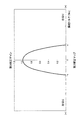
基本戻し電流演算部20は、ステアリングホイール1を中立位置へ戻す方向の基本戻し電流を操舵角センサ15の検出結果に基づいて演算するものである。具体的には、図3に示す基本マップを参照して、操舵角センサ15から入力された操舵角に対応する基本戻し電流を演算する。基本戻し電流は、戻し制御の基本となる電流である。
The basic return
図3に示す基本マップは、操舵角と基本戻し電流との関係を規定したマップであり、横軸が操舵角であり、縦軸が基本戻し電流である。横軸の+側は中立位置から右切り側の操舵角を示し、−側は中立位置から左切り側の操舵角を示す。また、縦軸の+側はステアリングホイール1を右切り方向へアシストする基本戻し電流であり、−側はステアリングホイール1を左切り方向へアシストする基本戻し電流である。基本マップの特性は、図3からわかるように、操舵角が右切り側である場合には、基本戻し電流は左切り方向へアシストする値となり、操舵角が左切り側である場合には、基本戻し電流は右切り方向へアシストする値となる。このように、基本マップを参照することによって出力される基本戻し電流は、ステアリングホイール1を中立位置へ戻す方向の電流となる。
The basic map shown in FIG. 3 is a map that defines the relationship between the steering angle and the basic return current. The horizontal axis is the steering angle, and the vertical axis is the basic return current. The + side of the horizontal axis represents the steering angle from the neutral position to the right turn side, and the − side represents the steering angle from the neutral position to the left turn side. Further, the + side of the vertical axis is a basic return current that assists the
図3に示す基本マップを詳しく説明する。ステアリングホイール1の中立位置近傍では、基本戻し電流がゼロとなる不感帯に設定される。これは、操舵角センサ15の検出誤差に起因する外乱の発生を防ぐためである。操舵角の絶対値が不感帯よりも大きくなると、基本戻し電流の絶対値は所定の傾きで大きくなる。この傾きを調整することによって、ステアリングホイール1が中立位置へ戻る際のドライバが感じる戻り感を変化させることができる。傾きを大きく設定するほど戻り感が大きくなる。操舵角の絶対値が所定値a以上の範囲では基本戻し電流がゼロに設定される。これは、基本戻し電流は、ステアリングホイール1の切り込み時にはドライバによる操舵力を増大させるように作用するものであるため、中立位置付近でのみ基本戻し電流が作用し、ステアリングホイール1を大きく切り込んだ際には基本戻し電流が作用しないようにするためである。また、ステアリングホイール1を大きく切り込んで戻す際の急な戻りを抑えるためである。
The basic map shown in FIG. 3 will be described in detail. In the vicinity of the neutral position of the
次に、第1補正ゲイン演算部21について説明する。
Next, the first
第1補正ゲイン演算部21は、基本戻し電流を補正する第1補正ゲインを車速センサ16の検出結果に基づいて演算するものである。具体的には、図4に示す第1補正マップを参照して、車速センサ16から入力された車速に対応する第1補正ゲインを演算する。セルフアライニングトルクは車速に応じて変化するため、車速に応じて変化する第1補正ゲインにて基本戻し電流を補正する。
The first
図4に示す第1補正マップは、車速と第1補正ゲインとの関係を規定したマップであり、横軸が車速であり、縦軸が第1補正ゲインである。第1補正ゲインは全車速域で1.0以下に設定される。つまり、第1補正ゲインは基本戻し電流を減らす値となる。セルフアライニングトルクは高速走行時には大きく低速走行時には小さいため、図4に示すように、第1補正ゲインは、低速領域では大きく、車速が大きくなるほど小さくなるように設定され、所定速度b以上ではゼロに設定される。また、所定の微低速cから停車状態までは所定の傾きで小さくなり、停車状態ではゼロに設定される。このように所定の傾きで第1補正ゲインを小さくしたのは、停車状態となり第1補正ゲインがゼロとなる際に生じる操舵の違和感を軽減するためである。 The first correction map shown in FIG. 4 is a map that defines the relationship between the vehicle speed and the first correction gain, the horizontal axis is the vehicle speed, and the vertical axis is the first correction gain. The first correction gain is set to 1.0 or less in the entire vehicle speed range. That is, the first correction gain is a value that reduces the basic return current. Since the self-aligning torque is large at high speeds and small at low speeds, as shown in FIG. 4, the first correction gain is set so as to increase as the vehicle speed increases and decreases as the vehicle speed increases. Set to Moreover, it becomes small with a predetermined inclination from the predetermined very low speed c to the stop state, and is set to zero in the stop state. The reason why the first correction gain is reduced at a predetermined inclination in this way is to reduce the uncomfortable feeling of steering that occurs when the vehicle enters a stop state and the first correction gain becomes zero.
次に、第2補正ゲイン演算部22について説明する。
Next, the second correction
第2補正ゲイン演算部22は、基本戻し電流を補正する第2補正ゲインをトルク変化量演算部26にて演算された操舵トルク変化量に基づいて演算するものである。具体的には、図5に示す第2補正マップを参照して、トルク変化量演算部26から入力された操舵トルク変化量に対応する第2補正ゲインを演算する。トルク変化量演算部26は、トルクセンサ12によって検出された操舵トルクから操舵トルク変化量を演算するものである。
The second
図5に示す第2補正マップは、操舵トルク変化量と第2補正ゲインとの関係を規定したマップであり、横軸が操舵トルク変化量であり、縦軸が第2補正ゲインである。第2補正ゲインは全操舵トルク変化量域で1.0以下に設定される。つまり、第2補正ゲインも、第1補正ゲインと同様に基本戻し電流を減らす値となる。 The second correction map shown in FIG. 5 is a map that defines the relationship between the steering torque change amount and the second correction gain, the horizontal axis is the steering torque change amount, and the vertical axis is the second correction gain. The second correction gain is set to 1.0 or less in the entire steering torque change amount region. That is, the second correction gain is also a value that reduces the basic return current, like the first correction gain.
図5に示すように、第2補正ゲインは、操舵トルク変化量が大きいほど小さい値となるように設定され、所定操舵トルク変化量d以上ではゼロに設定される。これにより、ステアリングホイール1を素早く切り込んだ際には、基本戻し電流は第2補正ゲインにて小さくなるように補正されるため、戻し制御によってドライバが重いと感じることがなく、操舵フィーリングが改善する。また、ステアリングホイール1を大きく切り込んだ後に手を離してステアリングホイール1を戻す際には、操舵トルク変化量が大きい初期は第2補正ゲインが小さいため、ステアリングホイール1はゆっくりと戻り始めるのに対して、操舵トルク変化量が小さくなる中立位置近傍では第2補正ゲインが除々に大きくなるため、ステアリングホイール1は素早く滑らかに戻る。このように、操舵状態から手を離した際に、ステアリングホイール1を滑らかに戻すことができる。以上のように、第2補正ゲインはドライバの操舵意思に応じて基本戻し電流を補正するものであり、基本戻し電流を第2補正ゲインにて補正することによって操舵時の違和感を軽減することができる。
As shown in FIG. 5, the second correction gain is set to be smaller as the steering torque change amount is larger, and is set to zero when the steering torque change amount is greater than or equal to d. As a result, when the
また、車両が砂利道等の凹凸のある路面を走行する際には、路面からの衝撃である所謂キックバックがステアリングホイール1に伝達されドライバの意思とは無関係にステアリングホイール1が回転する場合がある。キックバックによるステアリングホイール1の回転に対しても戻し制御が作用すると、ドライバの操舵意思とは無関係にステアリングホイール1が制御されてしまうことになるため、好ましくない。そこで、所定操舵トルク変化量dは、想定されるキックバックに伴うトルクの変化量よりも小さい値に設定するのが望ましい。これにより、キックバック発生時には、第2補正ゲインがゼロとなり、基本戻し電流はゼロとなるため、戻し制御が作用しなくなる。
Further, when the vehicle travels on an uneven road surface such as a gravel road, a so-called kickback that is an impact from the road surface is transmitted to the
次に、第3補正ゲイン演算部23について説明する。
Next, the third
第3補正ゲイン演算部23は、基本戻し電流を補正する第3補正ゲインをトルクセンサ12の検出結果に基づいて演算するものである。具体的には、図6に示す第3補正マップを参照して、トルクセンサ12から入力された操舵トルクに対応する第3補正ゲインを演算する。
The third
図6に示す第3補正マップは、操舵トルクと第3補正ゲインとの関係を規定したマップであり、横軸が操舵トルクであり、縦軸が第3補正ゲインである。横軸の+側は中立位置から右切り側の操舵トルクを示し、−側は中立位置から左切り側の操舵トルクを示す。第3補正ゲインは全操舵トルク域で1.0以下に設定される。つまり、第3補正ゲインも、第1補正ゲイン及び第2補正ゲインと同様に基本戻し電流を減らす値となる。 The third correction map shown in FIG. 6 is a map that defines the relationship between the steering torque and the third correction gain, the horizontal axis is the steering torque, and the vertical axis is the third correction gain. The + side of the horizontal axis represents the steering torque from the neutral position to the right turn side, and the − side represents the steering torque from the neutral position to the left turn side. The third correction gain is set to 1.0 or less in the entire steering torque range. That is, the third correction gain is also a value that reduces the basic return current, like the first correction gain and the second correction gain.
図6に示すように、第3補正ゲインは、操舵トルクの絶対値が大きいほど小さい値で、かつ操舵トルクの絶対値が所定値e以上でゼロに設定される。操舵トルクの絶対値が所定値eより小さい範囲では、操舵トルクの変化に対して第3補正ゲインが曲線状に変化するように設定される。所定値eは、ステアリングホイール1を切り込んでいる際には第3補正ゲインがゼロとなるように設定するのが望ましい。これにより、ステアリングホイール1を切り込んでいる際には、基本戻し電流は第3補正ゲインによる補正にてゼロとなるため、戻し制御によってドライバが重いと感じることがなく、操舵フィーリングが改善する。また、ステアリングホイール1を切り込んだ後に手を離してステアリングホイール1を戻す際には、操舵トルクが大きい初期は第3補正ゲインがゼロとなるため、ステアリングホイール1はゆっくりと戻り始めるのに対して、操舵トルクが小さくなる中立位置近傍では第3補正ゲインが除々に大きくなるため、ステアリングホイール1は素早く滑らかに戻る。このように、操舵状態から手を離した際に、ステアリングホイール1を滑らかに戻すことができる。以上のように、第3補正ゲインは、第2補正ゲインと同様に、ドライバの操舵意思に応じて基本戻し電流を補正するものであり、基本戻し電流を第3補正ゲインにて補正することによって操舵時の違和感を軽減することができる。また、ステアリングホイール1が中立位置近傍で保舵されている状態では、操舵トルクの絶対値は所定値eよりも小さいため、ステアリングホイール1を中立位置に保持するように戻し制御が作用する。
As shown in FIG. 6, the third correction gain is set to a smaller value as the absolute value of the steering torque is larger, and to zero when the absolute value of the steering torque is equal to or greater than a predetermined value e. In a range where the absolute value of the steering torque is smaller than the predetermined value e, the third correction gain is set so as to change in a curve with respect to the change of the steering torque. The predetermined value e is desirably set so that the third correction gain becomes zero when the
以上のようにして演算された基本戻し電流、第1補正ゲイン、第2補正ゲイン、及び第3補正ゲインは、図2に示すように、乗算器24にて乗算された後、ローパスフィルタ31及び上下限値リミッタ32にて処理され、戻し電流として加算器25にてアシストベース電流に加算される。なお、加算器25では、ギヤのフリクション等を補償する各種補償電流も加算される。加算器25から出力された制御電流によって電動モータ10の駆動が制御される。
The basic return current, the first correction gain, the second correction gain, and the third correction gain calculated as described above are multiplied by the
以上の実施形態によれば、以下に示す効果を奏する。 According to the above embodiment, there exist the effects shown below.
本実施形態は、ステアリングホイール1の切りと戻りの判定を行なわずに、戻し電流をアシストベース電流に加算して電動モータ10を駆動するものである。また、戻し電流は、操舵角に基づいて演算された基本戻し電流を、車速に基づいて演算された第1補正ゲイン、操舵トルクの変化量に基づいて演算された第2補正ゲイン、及び操舵トルクに基づいて演算された第3補正ゲインにて補正することによって演算されるものである。したがって、簡便な戻し制御によって操舵の違和感を軽減することができる。
In the present embodiment, the
なお、第3補正ゲインは、基本戻し電流を補正するための必須のファクターではなく、基本戻し電流を第1補正ゲイン及び第2補正ゲインのみにて補正することによって、簡便な戻し制御によって操舵の違和感を軽減するという一定の効果が得られる。 Note that the third correction gain is not an essential factor for correcting the basic return current, and the basic return current is corrected only by the first correction gain and the second correction gain, so that the steering return can be performed by simple return control. A certain effect of reducing the sense of incongruity can be obtained.
本発明は上記の実施の形態に限定されずに、その技術的な思想の範囲内において種々の変更がなしうることは明白である。 The present invention is not limited to the above-described embodiment, and it is obvious that various modifications can be made within the scope of the technical idea.
100 電動パワーステアリング装置
1 ステアリングホイール
10 電動モータ
12 トルクセンサ
13 コントローラ
15 操舵角センサ
16 車速センサ
19 ベース電流演算部
20 基本戻し電流演算部(基本戻し指令値演算部)
21 第1補正ゲイン演算部
22 第2補正ゲイン演算部
23 第3補正ゲイン演算部
DESCRIPTION OF
21 First correction
Claims (6)
前記ステアリングホイールを中立位置へ戻す方向の基本戻し指令値を、前記ステアリングホイールの操舵角を検出する操舵角検出器の検出結果に基づいて演算する基本戻し指令値演算部と、
前記基本戻し指令値を補正する第1補正ゲインを、車速を検出する車速検出器の検出結果に基づいて演算する第1補正ゲイン演算部と、
前記基本戻し指令値を補正する第2補正ゲインを前記トルクセンサによって検出された操舵トルクの変化量に基づいて演算する第2補正ゲイン演算部と、を備え、
前記基本戻し指令値を前記第1補正ゲイン及び前記第2補正ゲインにて補正して戻し指令値を演算し、当該戻し指令値を前記アシスト指令値に加算して前記電動モータを駆動し、
前記第2補正ゲインは、操舵トルクの変化量が大きいほど小さい値となるように設定され、操舵トルクの変化量が所定操舵トルク変化量以上ではゼロに設定されることを特徴とする電動パワーステアリング装置。 An electric power steering device that drives an electric motor by an assist command value calculated based on a detection result of a torque sensor that detects a steering torque input from a steering wheel, and assists the steering of the steering wheel by a driver,
A basic return command value calculation unit that calculates a basic return command value in a direction to return the steering wheel to a neutral position based on a detection result of a steering angle detector that detects a steering angle of the steering wheel;
A first correction gain calculator that calculates a first correction gain for correcting the basic return command value based on a detection result of a vehicle speed detector that detects a vehicle speed;
A second correction gain calculator that calculates a second correction gain for correcting the basic return command value based on a change amount of the steering torque detected by the torque sensor;
Correcting the basic return command value with the first correction gain and the second correction gain to calculate a return command value, adding the return command value to the assist command value, and driving the electric motor;
The electric power steering is characterized in that the second correction gain is set so as to be smaller as the change amount of the steering torque is larger, and is set to zero when the change amount of the steering torque is not less than a predetermined steering torque change amount. apparatus.
前記基本戻し指令値を前記第1補正ゲイン、前記第2補正ゲイン、及び第3補正ゲインにて補正して前記戻し指令値を演算し、当該戻し指令値を前記アシスト指令値に加算して前記電動モータを駆動することを特徴とする請求項1から3のいずれか一つに記載の電動パワーステアリング装置。 A third correction gain calculator for calculating a third correction gain for correcting the basic return command value based on the steering torque detected by the torque sensor;
The basic return command value is corrected with the first correction gain, the second correction gain, and the third correction gain, the return command value is calculated, and the return command value is added to the assist command value. The electric power steering apparatus according to any one of claims 1 to 3, wherein the electric motor is driven.
Priority Applications (5)
| Application Number | Priority Date | Filing Date | Title |
|---|---|---|---|
| JP2013121622A JP6155101B2 (en) | 2013-06-10 | 2013-06-10 | Electric power steering device |
| PCT/JP2014/064847 WO2014199882A1 (en) | 2013-06-10 | 2014-06-04 | Electric power steering device |
| US14/897,236 US9481392B2 (en) | 2013-06-10 | 2014-06-04 | Electric power steering device |
| EP14811079.4A EP3009332B1 (en) | 2013-06-10 | 2014-06-04 | Electric power steering device |
| CN201480032854.6A CN105324294B (en) | 2013-06-10 | 2014-06-04 | Driven steering device |
Applications Claiming Priority (1)
| Application Number | Priority Date | Filing Date | Title |
|---|---|---|---|
| JP2013121622A JP6155101B2 (en) | 2013-06-10 | 2013-06-10 | Electric power steering device |
Publications (3)
| Publication Number | Publication Date |
|---|---|
| JP2014237405A JP2014237405A (en) | 2014-12-18 |
| JP2014237405A5 JP2014237405A5 (en) | 2016-05-26 |
| JP6155101B2 true JP6155101B2 (en) | 2017-06-28 |
Family
ID=52022179
Family Applications (1)
| Application Number | Title | Priority Date | Filing Date |
|---|---|---|---|
| JP2013121622A Active JP6155101B2 (en) | 2013-06-10 | 2013-06-10 | Electric power steering device |
Country Status (5)
| Country | Link |
|---|---|
| US (1) | US9481392B2 (en) |
| EP (1) | EP3009332B1 (en) |
| JP (1) | JP6155101B2 (en) |
| CN (1) | CN105324294B (en) |
| WO (1) | WO2014199882A1 (en) |
Families Citing this family (6)
| Publication number | Priority date | Publication date | Assignee | Title |
|---|---|---|---|---|
| US20170072994A1 (en) * | 2015-09-14 | 2017-03-16 | Mando Corporation | Apparatus and method for controlling electric power steering system |
| JP6652742B2 (en) | 2016-01-14 | 2020-02-26 | 三菱自動車工業株式会社 | Electric power steering device |
| JP6409820B2 (en) * | 2016-05-02 | 2018-10-24 | マツダ株式会社 | Control device for electric power steering |
| JP6409821B2 (en) * | 2016-05-02 | 2018-10-24 | マツダ株式会社 | Control device for electric power steering |
| KR102020752B1 (en) * | 2017-12-22 | 2019-09-11 | 현대모비스 주식회사 | Apparatus for compensating torque of motor driven power steering system and method thereof |
| JP7240264B2 (en) * | 2019-06-12 | 2023-03-15 | Kyb株式会社 | electric power steering device |
Family Cites Families (17)
| Publication number | Priority date | Publication date | Assignee | Title |
|---|---|---|---|---|
| JP3047598B2 (en) * | 1992-01-30 | 2000-05-29 | オムロン株式会社 | Electric power steering device |
| JP3627120B2 (en) * | 1997-02-19 | 2005-03-09 | 光洋精工株式会社 | Vehicle steering system |
| JP3830750B2 (en) * | 2000-10-19 | 2006-10-11 | 株式会社ジェイテクト | Control device for electric power steering device |
| JP4622137B2 (en) * | 2001-04-11 | 2011-02-02 | 日産自動車株式会社 | Electric power steering control device |
| JP3966274B2 (en) * | 2003-12-04 | 2007-08-29 | トヨタ自動車株式会社 | Steering control device |
| JP4407936B2 (en) * | 2004-10-29 | 2010-02-03 | 株式会社ショーワ | Electric power steering device |
| JP2006168483A (en) * | 2004-12-14 | 2006-06-29 | Nissan Motor Co Ltd | Vehicle steering controller |
| JP4872298B2 (en) * | 2005-10-04 | 2012-02-08 | 日本精工株式会社 | Control device for electric power steering device |
| JP2007320383A (en) | 2006-05-31 | 2007-12-13 | Showa Corp | Electric power steering device |
| JP4997472B2 (en) * | 2007-01-09 | 2012-08-08 | 株式会社ジェイテクト | Electric power steering device |
| JP5003427B2 (en) * | 2007-11-20 | 2012-08-15 | トヨタ自動車株式会社 | Steering control device and vehicle steering device using the same |
| JP4603593B2 (en) * | 2008-04-23 | 2010-12-22 | 本田技研工業株式会社 | Electric power steering device |
| JP2009292286A (en) * | 2008-06-04 | 2009-12-17 | Honda Motor Co Ltd | Steering wheel return control device |
| JP5208684B2 (en) | 2008-11-10 | 2013-06-12 | 中国電力株式会社 | Ground fault protection relay system |
| KR101022547B1 (en) * | 2009-04-17 | 2011-03-16 | 현대모비스 주식회사 | Steer recovering method for Motor Driven Power Steering |
| JP5821659B2 (en) * | 2011-12-22 | 2015-11-24 | トヨタ自動車株式会社 | Vehicle steering system |
| JP6287768B2 (en) * | 2014-11-10 | 2018-03-07 | 株式会社デンソー | Motor control device |
-
2013
- 2013-06-10 JP JP2013121622A patent/JP6155101B2/en active Active
-
2014
- 2014-06-04 US US14/897,236 patent/US9481392B2/en active Active
- 2014-06-04 CN CN201480032854.6A patent/CN105324294B/en active Active
- 2014-06-04 WO PCT/JP2014/064847 patent/WO2014199882A1/en active Application Filing
- 2014-06-04 EP EP14811079.4A patent/EP3009332B1/en active Active
Also Published As
| Publication number | Publication date |
|---|---|
| CN105324294B (en) | 2017-08-22 |
| US9481392B2 (en) | 2016-11-01 |
| WO2014199882A1 (en) | 2014-12-18 |
| EP3009332B1 (en) | 2018-10-31 |
| EP3009332A1 (en) | 2016-04-20 |
| EP3009332A4 (en) | 2017-03-15 |
| US20160144889A1 (en) | 2016-05-26 |
| CN105324294A (en) | 2016-02-10 |
| JP2014237405A (en) | 2014-12-18 |
Similar Documents
| Publication | Publication Date | Title |
|---|---|---|
| JP6155101B2 (en) | Electric power steering device | |
| JP5407171B2 (en) | Electric power steering device | |
| JP4603593B2 (en) | Electric power steering device | |
| JP6220687B2 (en) | Electric power steering device | |
| US8229627B2 (en) | Vehicle steering apparatus | |
| JP2006248252A (en) | Control device of electric power steering device | |
| JP2009113512A (en) | Controller for electrically-operated power steering device | |
| JP6220688B2 (en) | Electric power steering device | |
| JP2008230580A (en) | Electric power steering device | |
| JP5244031B2 (en) | Vehicle steering system | |
| JP2008024073A (en) | Electric power steering device | |
| JP4552649B2 (en) | Steering control device | |
| KR101172098B1 (en) | Electric Power Steering System for Reducing Reaction in Active Front Steering | |
| JP4202357B2 (en) | Vehicle steering system | |
| JP4984712B2 (en) | Control device for electric power steering device | |
| JP5444819B2 (en) | Electric power steering device | |
| JP2009208671A (en) | Electric power steering device | |
| JP5098622B2 (en) | Electric power steering device | |
| JP2012236602A (en) | Electric power steering device |
Legal Events
| Date | Code | Title | Description |
|---|---|---|---|
| A521 | Request for written amendment filed |
Free format text: JAPANESE INTERMEDIATE CODE: A523 Effective date: 20160328 |
|
| A621 | Written request for application examination |
Free format text: JAPANESE INTERMEDIATE CODE: A621 Effective date: 20160328 |
|
| A131 | Notification of reasons for refusal |
Free format text: JAPANESE INTERMEDIATE CODE: A131 Effective date: 20161206 |
|
| RD02 | Notification of acceptance of power of attorney |
Free format text: JAPANESE INTERMEDIATE CODE: A7422 Effective date: 20161216 |
|
| A521 | Request for written amendment filed |
Free format text: JAPANESE INTERMEDIATE CODE: A523 Effective date: 20170202 |
|
| A131 | Notification of reasons for refusal |
Free format text: JAPANESE INTERMEDIATE CODE: A131 Effective date: 20170221 |
|
| TRDD | Decision of grant or rejection written | ||
| A01 | Written decision to grant a patent or to grant a registration (utility model) |
Free format text: JAPANESE INTERMEDIATE CODE: A01 Effective date: 20170509 |
|
| A61 | First payment of annual fees (during grant procedure) |
Free format text: JAPANESE INTERMEDIATE CODE: A61 Effective date: 20170605 |
|
| R150 | Certificate of patent or registration of utility model |
Ref document number: 6155101 Country of ref document: JP Free format text: JAPANESE INTERMEDIATE CODE: R150 |
|
| R250 | Receipt of annual fees |
Free format text: JAPANESE INTERMEDIATE CODE: R250 |
|
| R250 | Receipt of annual fees |
Free format text: JAPANESE INTERMEDIATE CODE: R250 |
|
| R250 | Receipt of annual fees |
Free format text: JAPANESE INTERMEDIATE CODE: R250 |
|
| R250 | Receipt of annual fees |
Free format text: JAPANESE INTERMEDIATE CODE: R250 |
|
| S533 | Written request for registration of change of name |
Free format text: JAPANESE INTERMEDIATE CODE: R313533 |
|
| R350 | Written notification of registration of transfer |
Free format text: JAPANESE INTERMEDIATE CODE: R350 |