EP3009332B1 - Electric power steering device - Google Patents
Electric power steering device Download PDFInfo
- Publication number
- EP3009332B1 EP3009332B1 EP14811079.4A EP14811079A EP3009332B1 EP 3009332 B1 EP3009332 B1 EP 3009332B1 EP 14811079 A EP14811079 A EP 14811079A EP 3009332 B1 EP3009332 B1 EP 3009332B1
- Authority
- EP
- European Patent Office
- Prior art keywords
- correction gain
- steering
- command value
- torque
- electric power
- Prior art date
- Legal status (The legal status is an assumption and is not a legal conclusion. Google has not performed a legal analysis and makes no representation as to the accuracy of the status listed.)
- Active
Links
Images


Classifications
-
- B—PERFORMING OPERATIONS; TRANSPORTING
- B62—LAND VEHICLES FOR TRAVELLING OTHERWISE THAN ON RAILS
- B62D—MOTOR VEHICLES; TRAILERS
- B62D5/00—Power-assisted or power-driven steering
- B62D5/04—Power-assisted or power-driven steering electrical, e.g. using an electric servo-motor connected to, or forming part of, the steering gear
- B62D5/0457—Power-assisted or power-driven steering electrical, e.g. using an electric servo-motor connected to, or forming part of, the steering gear characterised by control features of the drive means as such
- B62D5/046—Controlling the motor
- B62D5/0466—Controlling the motor for returning the steering wheel to neutral position
Definitions
- the present invention relates to an electric power steering device.
- Some conventional electric power steering devices use an electric motor for assisting steering to perform return control of a steering wheel.
- JP2007-320383A discloses such an electric power steering device that returns a steering wheel smoothly by performing steering wheel return control, so as not to give an uncomfortable feeling to a driver, when both of the following two conditions are satisfied at the same time: a condition that steering torque is a low torque threshold value or less and the steering wheel can be judged as being in a state of let go; and a condition that a torque change rate is a predetermined torque change rate threshold value or less.
- Another example of electric power steering device can be found in the Patent No. EP 1944220 .
- EP1944220 discloses the preamble of the independent claim.
- the steering wheel return control becomes complicated as whether or not the two conditions are satisfied is monitored and the steering wheel return control is performed when it is judged that the two conditions are satisfied.
- the basic return command value is corrected by the first correction gain and the second correction gain so as to calculate a return command value, and the return command value is added to the assist command value so as to drive the electric motor.
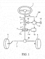
- the electric power steering device 100 includes an input shaft 7 that is rotated in response to operation of a steering wheel 1 by a driver, and an output shaft 3 whose upper end is connected to the input shaft 7 via a torsion bar 4 and whose lower end is linked to a rack shaft 5.
- the electric power steering device 100 steers wheels 6 by moving the rack shaft 5, meshing with a pinion 3a provided at the lower end of the output shaft 3, in the axial direction.
- the input shaft 7 and the output shaft 3 form a steering shaft 2.
- the electric power steering device 100 includes an electric motor 10 as a power source for assisting steering of the steering wheel 1 by the driver, a reduction gear 11 for reducing speed of rotation of the electric motor 10 and transmitting it to the steering shaft 2, a torque sensor 12 for detecting steering torque inputted from the steering wheel 1, and a controller 13 for controlling driving of the electric motor 10 on the basis of detection results of the torque sensor 12.
- the reduction gear 11 is formed of a worm shaft 11a that is connected to an output shaft of the electric motor 10, and a worm wheel 11b that is connected to the output shaft 3 and meshes with the worm shaft 11a. Torque, outputted from the electric motor 10, is transmitted from the worm shaft 11a to the worm wheel 11b, and is given to the output shaft 3 as assist torque.
- the torque sensor 12 detects the steering torque, given to the torsion bar 4, on the basis of relative rotation of the input shaft 7 and the output shaft 3.
- the torque sensor 12 outputs a voltage signal corresponding to the detected steering torque to the controller 13.
- the controller 13 calculates the torque outputted from the electric motor 10, and controls the driving of the electric motor 10 so that this torque is generated.
- the electric power steering device 100 drives the electric motor on the basis of the detection results of the torque sensor 12 that detects the steering torque inputted from the steering wheel 1, and assists the steering of the steering wheel 1 by the driver.
- the steering shaft 2 is provided with a steering angle sensor 15 as a steering angle detector for detecting a steering angle (absolute steering angle) of the steering wheel 1. Detection results of the steering angle sensor 15 are outputted to the controller 13.
- the steering angle sensor 15 When the steering wheel 1 is in a neutral position, the steering angle sensor 15 outputs zero as the steering angle.
- the steering angle sensor 15 When the steering wheel 1 is steered from the neutral position toward the right-turning direction, the steering angle sensor 15 outputs the steering angle with a plus sign in response to the rotation of the steering wheel 1. Meanwhile, when the steering wheel 1 is steered from the neutral position toward the left-turning direction, the steering angle sensor 15 outputs the steering angle with a minus sign in response to the rotation of the steering wheel 1.
- the controller 13 includes a CPU for controlling operation of the electric motor 10, ROM for storing control programs, set values and the like that are required for the processing operation of the CPU, and RAM for temporarily storing information detected by the various sensors such as the torque sensor 12, the steering angle sensor 15, and the vehicle speed sensor 16.
- self-aligning torque acts for returning the steering wheel 1 to the neutral position.
- This self-aligning torque is high when traveling at a high speed and low when traveling at a low speed.
- returnability of the steering wheel 1 to the neutral position is deteriorated due to gear friction of a steering system, such as the worm shaft 11a and the worm wheel 11b.
- the electric power steering device 100 performs return control for improving the returnability of the steering wheel 1 to the neutral position even when the vehicle is traveling at a low speed.
- the controller 13 calculates, in a base current calculation unit 19, an assist base current (assist command value) for controlling the driving of the electric motor 10 on the basis of the detection results of the torque sensor 12. Meanwhile, the controller 13 calculates, in a basic return current calculation unit (basic return command value calculation unit) 20, a basic return current in the direction returning the steering wheel 1 to the neutral position, as well as calculates, in a first correction gain calculation unit 21, a second correction gain calculation unit 22, and a third correction gain calculation unit 23, a first correction gain, a second correction gain, and a third correction gain for correcting the basic return current, and calculates, in a multiplier 24, a return current (return command value) by multiplying the basic return current by the first correction gain, the second correction gain, and the third correction gain.
- the calculated return current is added to the assist base current in an adder 25.
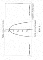
- the basic return current calculation unit 20 calculates the basic return current in the direction returning the steering wheel 1 to the neutral position on the basis of the detection results of the steering angle sensor 15. Specifically, by referring to a basic map as illustrated in Fig. 3 , the basic return current calculation unit 20 calculates the basic return current corresponding to the steering angle inputted from the steering angle sensor 15.
- the basic return current is a current that is the basis of the return control.
- the basic map as illustrated in Fig. 3 is a map defining the relationship between the steering angle and the basic return current, in which the horizontal axis represents the steering angle, and the vertical axis represents the basic return current.
- the plus side represents the steering angle on the right-turning side from the neutral position
- the minus side represents the steering angle on the left-turning side from the neutral position.
- the plus side represents the basic return current that assists the steering wheel 1 toward the right-turning direction
- the minus side represents the basic return current that assists the steering wheel 1 toward the left-turning direction.
- the basic map is characterized in that, when the steering angle is on the right-turning side, the basic return current has a value assisting toward the left-turning direction and, when the steering angle is on the left-turning side, the basic return current has a value assisting toward the right-turning direction.
- the basic return current outputted by referring to the basic map, is the current in the direction returning the steering wheel 1 to the neutral position.
- a dead band is set in the vicinity of the neutral position of the steering wheel 1, in which the basic return current becomes zero. This is to prevent occurrence of disturbance caused by a detection error of the steering angle sensor 15.
- an absolute value of the steering angle becomes greater than the dead band
- an absolute value of the basic return current increases with a specified inclination. By adjusting this inclination, it is possible to change a feeling of return that the driver feels when the steering wheel 1 returns to the neutral position.
- the inclination is set to be greater, the feeling of return increases.
- the absolute value of the steering angle is a predetermined value a or more, the basic return current is set to zero.
- the first correction gain calculation unit 21 calculates the first correction gain for correcting the basic return current on the basis of the detection results of the vehicle speed sensor 16. Specifically, by referring to a first correction map as illustrated in Fig. 4 , the first correction gain calculation unit 21 calculates the first correction gain that corresponds to the vehicle speed inputted from the vehicle speed sensor 16. As the self-aligning torque changes in response to the vehicle speed, the basic return current is corrected by the first correction gain that changes in response to the vehicle speed.
- the first correction map as illustrated in Fig. 4 is a map defining the relationship between the vehicle speed and the first correction gain, in which the horizontal axis represents the vehicle speed, and the vertical axis represents the first correction gain.
- the first correction gain is set to 1.0 or less over the entire range of the vehicle speed. In other words, the first correction gain is a value causing the basic return current to decrease.
- the first correction gain is set to be higher in the low speed region and set to be lower as the vehicle speed increases, as illustrated in Fig. 4 , and is set to zero at a predetermined speed b or more.
- the first correction gain decreases with a specified inclination from a predetermined very low speed c to a vehicle stop state, and is set to zero in the vehicle stop state.
- the first correction gain is thus decreased with the specified inclination in order to reduce an uncomfortable feeling upon steering, caused in the vehicle stop state when the first correction gain becomes zero.
- the second correction gain calculation unit 22 calculates the second correction gain for correcting the basic return current on the basis of a steering torque change amount calculated by a torque change amount calculation unit 26. Specifically, by referring to a second correction map as illustrated in Fig. 5 , the second correction gain calculation unit 22 calculates the second correction gain that corresponds to the steering torque change amount inputted from the torque change amount calculation unit 26. The torque change amount calculation unit 26 calculates the steering torque change amount from the steering torque detected by the torque sensor 12.
- the second correction map as illustrated in Fig. 5 is a map defining the relationship between the steering torque change amount and the second correction gain, in which the horizontal axis represents the steering torque change amount, and the vertical axis represents the second correction gain.
- the second correction gain is set to 1.0 or less over the entire range of the steering torque change amount. In other words, the second correction gain is also a value causing the basic return current to decrease, similarly to the first correction gain.
- the second correction gain is set to have a smaller value as the steering torque change amount increases, and is set to zero when the steering torque change amount is equal to or greater than a predetermined steering torque change amount d.
- the basic return current is corrected to decrease by the second correction gain when the steering wheel 1 is turned quickly, which makes it possible to improve a steering feeling without causing the driver to feel as if the steering is heavy by the return control.
- the second correction gain corrects the basic return current according to a driver's steering intention and, by correcting the basic return current by the second correction gain, an uncomfortable feeling upon steering can be reduced.
- the steering wheel 1 When the vehicle travels on roads with uneven spots, such as on gravel roads, the steering wheel 1 sometimes rotates irrespective of the driver's intention, because so-called kickback, as an impact from the road, is transmitted to the steering wheel 1.
- kickback as an impact from the road
- the return control is also applied to the rotation of the steering wheel 1 caused by the kickback, the steering wheel 1 is controlled irrespective of the driver's steering intention, which is not favorable. For this reason, it is desirable to set the predetermined steering torque change amount d to have a smaller value than the torque change amount caused by the assumed kickback.
- the second correction gain becomes zero and the basic return current becomes zero when the kickback is caused, the return control is not applied.
- the third correction gain calculation unit 23 calculates the third correction gain for correcting the basic return current on the basis of the detection results of the torque sensor 12. Specifically, by referring to a third correction map as illustrated in Fig. 6 , the third correction gain calculation unit 23 calculates the third correction gain that corresponds to the steering torque inputted from the torque sensor 12.
- the third correction map as illustrated in Fig. 6 is a map defining the relationship between the steering torque and the third correction gain, in which the horizontal axis represents the steering torque, and the vertical axis represents the third correction gain.
- the plus side represents the steering torque on the right-turning side from the neutral position
- the minus side represents the steering torque on the left-turning side from the neutral position.
- the third correction gain is set to 1.0 or less over the entire range of the steering torque.
- the third correction gain is also a value causing the basic return current to decrease, similarly to the first correction gain and the second correction gain.
- the third correction gain is set to have a smaller value as the absolute value of the steering torque increases, and is set to zero when the absolute value of the steering torque is equal to or greater than a predetermined value e.
- the third correction gain is set to change in a curve shape in response to the change in the steering torque.
- the predetermined value e is desirably set in such a manner that the third correction gain becomes zero when the steering wheel 1 is turned.
- the third correction gain corrects the basic return current according to the driver's steering intention and, by correcting the basic return current by the third correction gain, the uncomfortable feeling upon steering can be reduced, similarly to the second correction gain.
- the thus-calculated basic return current, first correction gain, second correction gain, and third correction gain are subjected to multiplication in the multiplier 24, as illustrated in Fig. 2 , processed by a low pass filter 31 and an upper and lower limiter 32, and added, as the return current, to the assist base current in the adder 25. It should be noted that, in the adder 25, various compensation currents are also added for compensating for the gear friction and the like.
- a control current, outputted from the adder 25, controls the driving of the electric motor 10.
- the electric motor 10 is driven by adding the return current to the assist base current without determining the turning and returning of the steering wheel 1.
- the return current is calculated by correcting the basic return current, that is calculated on the basis of the steering angle, by the first correction gain that is calculated on the basis of the vehicle speed, the second correction gain that is calculated on the basis of the steering torque change amount, and the third correction gain that is calculated on the basis of the steering torque. Therefore, the uncomfortable feeling upon steering can be reduced by a simple return control.
- the third correction gain is not an essential factor for correcting the basic return current. It is possible to provide certain degrees of effects of reducing the uncomfortable feeling upon steering by the simple return control when the basic return current is corrected by only the first correction gain and the second correction gain.
Description
- The present invention relates to an electric power steering device.
- Some conventional electric power steering devices use an electric motor for assisting steering to perform return control of a steering wheel.
-
JP2007-320383A
Another example of electric power steering device can be found in the Patent No.EP 1944220 . -
EP1944220 discloses the preamble of the independent claim. - According to the electric power steering device as described in
JP2007-320383A - It is an object of the present invention to reduce an uncomfortable feeling upon steering by simple return control.
- According to one aspect of the present invention, an electric power steering device for driving an electric motor by an assist command value calculated on the basis of detection results of a torque sensor detecting steering torque inputted from a steering wheel, and for assisting steering of the steering wheel by a driver includes: a basic return command value calculation unit configured to calculate a basic return command value in a direction returning the steering wheel to a neutral position, on the basis of detection results of a steering angle detector detecting a steering angle of the steering wheel; a first correction gain calculation unit configured to calculate a first correction gain correcting the basic return command value, on the basis of detection results of a vehicle speed detector detecting vehicle speed; and a second correction gain calculation unit configured to calculate a second correction gain correcting the basic return command value, on the basis of a change amount of the steering torque detected by the torque sensor. The basic return command value is corrected by the first correction gain and the second correction gain so as to calculate a return command value, and the return command value is added to the assist command value so as to drive the electric motor.
-
-
Fig. 1 is a configuration diagram of an electric power steering device according to an embodiment of the present invention; -
Fig. 2 is a control block diagram of the electric power steering device according to the embodiment of the present invention; -
Fig. 3 is a basic map for calculating a basic return current; -
Fig. 4 is a first correction map for calculating a first correction gain; -
Fig. 5 is a second correction map for calculating a second correction gain; and -
Fig. 6 is a third correction map for calculating a third correction gain. - Hereinafter, an embodiment of the present invention will be explained with reference to the drawings.
- First, the overall structure of an electric
power steering device 100 according to the embodiment of the present invention will be explained with reference toFig. 1 . - The electric
power steering device 100 includes aninput shaft 7 that is rotated in response to operation of asteering wheel 1 by a driver, and an output shaft 3 whose upper end is connected to theinput shaft 7 via a torsion bar 4 and whose lower end is linked to arack shaft 5. The electricpower steering device 100steers wheels 6 by moving therack shaft 5, meshing with apinion 3a provided at the lower end of the output shaft 3, in the axial direction. Theinput shaft 7 and the output shaft 3 form asteering shaft 2. - Further, the electric
power steering device 100 includes anelectric motor 10 as a power source for assisting steering of thesteering wheel 1 by the driver, areduction gear 11 for reducing speed of rotation of theelectric motor 10 and transmitting it to thesteering shaft 2, atorque sensor 12 for detecting steering torque inputted from thesteering wheel 1, and acontroller 13 for controlling driving of theelectric motor 10 on the basis of detection results of thetorque sensor 12. - The
reduction gear 11 is formed of aworm shaft 11a that is connected to an output shaft of theelectric motor 10, and aworm wheel 11b that is connected to the output shaft 3 and meshes with theworm shaft 11a. Torque, outputted from theelectric motor 10, is transmitted from theworm shaft 11a to theworm wheel 11b, and is given to the output shaft 3 as assist torque. - The
torque sensor 12 detects the steering torque, given to the torsion bar 4, on the basis of relative rotation of theinput shaft 7 and the output shaft 3. Thetorque sensor 12 outputs a voltage signal corresponding to the detected steering torque to thecontroller 13. On the basis of the voltage signal from thetorque sensor 12, thecontroller 13 calculates the torque outputted from theelectric motor 10, and controls the driving of theelectric motor 10 so that this torque is generated. Thus, the electricpower steering device 100 drives the electric motor on the basis of the detection results of thetorque sensor 12 that detects the steering torque inputted from thesteering wheel 1, and assists the steering of thesteering wheel 1 by the driver. - The
steering shaft 2 is provided with asteering angle sensor 15 as a steering angle detector for detecting a steering angle (absolute steering angle) of thesteering wheel 1. Detection results of thesteering angle sensor 15 are outputted to thecontroller 13. When thesteering wheel 1 is in a neutral position, thesteering angle sensor 15 outputs zero as the steering angle. When thesteering wheel 1 is steered from the neutral position toward the right-turning direction, thesteering angle sensor 15 outputs the steering angle with a plus sign in response to the rotation of thesteering wheel 1. Meanwhile, when thesteering wheel 1 is steered from the neutral position toward the left-turning direction, thesteering angle sensor 15 outputs the steering angle with a minus sign in response to the rotation of thesteering wheel 1. - In addition, detection results of a
vehicle speed sensor 16, as a vehicle speed detector for detecting vehicle speed, are inputted to thecontroller 13. - The
controller 13 includes a CPU for controlling operation of theelectric motor 10, ROM for storing control programs, set values and the like that are required for the processing operation of the CPU, and RAM for temporarily storing information detected by the various sensors such as thetorque sensor 12, thesteering angle sensor 15, and thevehicle speed sensor 16. - When the vehicle is traveling, self-aligning torque acts for returning the
steering wheel 1 to the neutral position. This self-aligning torque is high when traveling at a high speed and low when traveling at a low speed. When traveling at low speed with low self-aligning torque, returnability of thesteering wheel 1 to the neutral position is deteriorated due to gear friction of a steering system, such as theworm shaft 11a and theworm wheel 11b. For this reason, the electricpower steering device 100 performs return control for improving the returnability of thesteering wheel 1 to the neutral position even when the vehicle is traveling at a low speed. - Next, the return control will be explained with reference to
Fig. 2 to Fig. 6 . - As illustrated in
Fig. 2 , thecontroller 13 calculates, in a basecurrent calculation unit 19, an assist base current (assist command value) for controlling the driving of theelectric motor 10 on the basis of the detection results of thetorque sensor 12. Meanwhile, thecontroller 13 calculates, in a basic return current calculation unit (basic return command value calculation unit) 20, a basic return current in the direction returning thesteering wheel 1 to the neutral position, as well as calculates, in a first correctiongain calculation unit 21, a second correctiongain calculation unit 22, and a third correctiongain calculation unit 23, a first correction gain, a second correction gain, and a third correction gain for correcting the basic return current, and calculates, in amultiplier 24, a return current (return command value) by multiplying the basic return current by the first correction gain, the second correction gain, and the third correction gain. The calculated return current is added to the assist base current in anadder 25. - Hereinafter, the basic return
current calculation unit 20, the first correctiongain calculation unit 21, the second correctiongain calculation unit 22, and the third correctiongain calculation unit 23 will be explained. - First, the basic return
current calculation unit 20 will be explained. - The basic return
current calculation unit 20 calculates the basic return current in the direction returning thesteering wheel 1 to the neutral position on the basis of the detection results of thesteering angle sensor 15. Specifically, by referring to a basic map as illustrated inFig. 3 , the basic returncurrent calculation unit 20 calculates the basic return current corresponding to the steering angle inputted from thesteering angle sensor 15. The basic return current is a current that is the basis of the return control. - The basic map as illustrated in
Fig. 3 is a map defining the relationship between the steering angle and the basic return current, in which the horizontal axis represents the steering angle, and the vertical axis represents the basic return current. With the horizontal axis, the plus side represents the steering angle on the right-turning side from the neutral position, and the minus side represents the steering angle on the left-turning side from the neutral position. Further, with the vertical axis, the plus side represents the basic return current that assists thesteering wheel 1 toward the right-turning direction, and the minus side represents the basic return current that assists thesteering wheel 1 toward the left-turning direction. As is clear fromFig. 3 , the basic map is characterized in that, when the steering angle is on the right-turning side, the basic return current has a value assisting toward the left-turning direction and, when the steering angle is on the left-turning side, the basic return current has a value assisting toward the right-turning direction. Thus, the basic return current, outputted by referring to the basic map, is the current in the direction returning thesteering wheel 1 to the neutral position. - The basic map as illustrated in
Fig. 3 will be explained in detail. A dead band is set in the vicinity of the neutral position of thesteering wheel 1, in which the basic return current becomes zero. This is to prevent occurrence of disturbance caused by a detection error of thesteering angle sensor 15. When an absolute value of the steering angle becomes greater than the dead band, an absolute value of the basic return current increases with a specified inclination. By adjusting this inclination, it is possible to change a feeling of return that the driver feels when thesteering wheel 1 returns to the neutral position. When the inclination is set to be greater, the feeling of return increases. In a range where the absolute value of the steering angle is a predetermined value a or more, the basic return current is set to zero. This is because, as the basic return current acts to increase a steering force by the driver upon turning thesteering wheel 1, the basic return current is allowed to act only in the vicinity of the neutral position and is not allowed to act when thesteering wheel 1 is greatly turned. It is also because, when thesteering wheel 1 is greatly turned and then returned, sudden returning should be prevented. - Next, the first correction
gain calculation unit 21 will be explained. - The first correction
gain calculation unit 21 calculates the first correction gain for correcting the basic return current on the basis of the detection results of thevehicle speed sensor 16. Specifically, by referring to a first correction map as illustrated inFig. 4 , the first correctiongain calculation unit 21 calculates the first correction gain that corresponds to the vehicle speed inputted from thevehicle speed sensor 16. As the self-aligning torque changes in response to the vehicle speed, the basic return current is corrected by the first correction gain that changes in response to the vehicle speed. - The first correction map as illustrated in
Fig. 4 is a map defining the relationship between the vehicle speed and the first correction gain, in which the horizontal axis represents the vehicle speed, and the vertical axis represents the first correction gain. The first correction gain is set to 1.0 or less over the entire range of the vehicle speed. In other words, the first correction gain is a value causing the basic return current to decrease. As the self-aligning torque is high when traveling at a high speed and low when traveling at a low speed, the first correction gain is set to be higher in the low speed region and set to be lower as the vehicle speed increases, as illustrated inFig. 4 , and is set to zero at a predetermined speed b or more. Further, the first correction gain decreases with a specified inclination from a predetermined very low speed c to a vehicle stop state, and is set to zero in the vehicle stop state. The first correction gain is thus decreased with the specified inclination in order to reduce an uncomfortable feeling upon steering, caused in the vehicle stop state when the first correction gain becomes zero. - Next, the second correction
gain calculation unit 22 will be explained. - The second correction
gain calculation unit 22 calculates the second correction gain for correcting the basic return current on the basis of a steering torque change amount calculated by a torque changeamount calculation unit 26. Specifically, by referring to a second correction map as illustrated inFig. 5 , the second correctiongain calculation unit 22 calculates the second correction gain that corresponds to the steering torque change amount inputted from the torque changeamount calculation unit 26. The torque changeamount calculation unit 26 calculates the steering torque change amount from the steering torque detected by thetorque sensor 12. - The second correction map as illustrated in
Fig. 5 is a map defining the relationship between the steering torque change amount and the second correction gain, in which the horizontal axis represents the steering torque change amount, and the vertical axis represents the second correction gain. The second correction gain is set to 1.0 or less over the entire range of the steering torque change amount. In other words, the second correction gain is also a value causing the basic return current to decrease, similarly to the first correction gain. - As illustrated in
Fig. 5 , the second correction gain is set to have a smaller value as the steering torque change amount increases, and is set to zero when the steering torque change amount is equal to or greater than a predetermined steering torque change amount d. Thereby, the basic return current is corrected to decrease by the second correction gain when thesteering wheel 1 is turned quickly, which makes it possible to improve a steering feeling without causing the driver to feel as if the steering is heavy by the return control. When thesteering wheel 1 is greatly turned and then returned by releasing a hand therefrom, the returning of thesteering wheel 1 begins slowly as the second correction gain is low in the early stage when the steering torque change amount is large, but in the vicinity of the neutral position, where the steering torque change amount decreases, the returning of thesteering wheel 1 is performed quickly and smoothly as the second correction gain gradually increases. Thus, the returning of thesteering wheel 1 can be performed smoothly when the hand is released from the steering state. As has been described thus far, the second correction gain corrects the basic return current according to a driver's steering intention and, by correcting the basic return current by the second correction gain, an uncomfortable feeling upon steering can be reduced. - When the vehicle travels on roads with uneven spots, such as on gravel roads, the
steering wheel 1 sometimes rotates irrespective of the driver's intention, because so-called kickback, as an impact from the road, is transmitted to thesteering wheel 1. When the return control is also applied to the rotation of thesteering wheel 1 caused by the kickback, thesteering wheel 1 is controlled irrespective of the driver's steering intention, which is not favorable. For this reason, it is desirable to set the predetermined steering torque change amount d to have a smaller value than the torque change amount caused by the assumed kickback. As the second correction gain becomes zero and the basic return current becomes zero when the kickback is caused, the return control is not applied. - Next, the third correction
gain calculation unit 23 will be explained. - The third correction
gain calculation unit 23 calculates the third correction gain for correcting the basic return current on the basis of the detection results of thetorque sensor 12. Specifically, by referring to a third correction map as illustrated inFig. 6 , the third correctiongain calculation unit 23 calculates the third correction gain that corresponds to the steering torque inputted from thetorque sensor 12. - The third correction map as illustrated in
Fig. 6 is a map defining the relationship between the steering torque and the third correction gain, in which the horizontal axis represents the steering torque, and the vertical axis represents the third correction gain. With the horizontal axis, the plus side represents the steering torque on the right-turning side from the neutral position, and the minus side represents the steering torque on the left-turning side from the neutral position. The third correction gain is set to 1.0 or less over the entire range of the steering torque. In other words, the third correction gain is also a value causing the basic return current to decrease, similarly to the first correction gain and the second correction gain. - As illustrated in
Fig. 6 , the third correction gain is set to have a smaller value as the absolute value of the steering torque increases, and is set to zero when the absolute value of the steering torque is equal to or greater than a predetermined value e. In the range where the absolute value of the steering torque is smaller than the predetermined value e, the third correction gain is set to change in a curve shape in response to the change in the steering torque. The predetermined value e is desirably set in such a manner that the third correction gain becomes zero when thesteering wheel 1 is turned. Thereby, the basic return current is corrected to become zero by the third correction gain when thesteering wheel 1 is turned, which makes it possible to improve the steering feeling without causing the driver to feel as if the steering is heavy by the return control. When thesteering wheel 1 is turned and then returned by releasing a hand therefrom, the returning of thesteering wheel 1 begins slowly as the third correction gain becomes zero in the early stage when the steering torque is high, but in the vicinity of the neutral position, where the steering torque becomes low, the returning of thesteering wheel 1 is made quickly and smoothly as the third correction gain gradually increases. Thus, the returning of thesteering wheel 1 can be made smoothly when the hand is released from the steering state. As has been described thus far, the third correction gain corrects the basic return current according to the driver's steering intention and, by correcting the basic return current by the third correction gain, the uncomfortable feeling upon steering can be reduced, similarly to the second correction gain. When thesteering wheel 1 is held in the vicinity of the neutral position, the absolute value of the steering torque is smaller than the predetermined value e, hence the return control is applied so as to hold thesteering wheel 1 at the neutral position. - The thus-calculated basic return current, first correction gain, second correction gain, and third correction gain are subjected to multiplication in the
multiplier 24, as illustrated inFig. 2 , processed by alow pass filter 31 and an upper andlower limiter 32, and added, as the return current, to the assist base current in theadder 25. It should be noted that, in theadder 25, various compensation currents are also added for compensating for the gear friction and the like. A control current, outputted from theadder 25, controls the driving of theelectric motor 10. - The following effects can be obtained by the above-described embodiment.
- According to this embodiment, the
electric motor 10 is driven by adding the return current to the assist base current without determining the turning and returning of thesteering wheel 1. The return current is calculated by correcting the basic return current, that is calculated on the basis of the steering angle, by the first correction gain that is calculated on the basis of the vehicle speed, the second correction gain that is calculated on the basis of the steering torque change amount, and the third correction gain that is calculated on the basis of the steering torque. Therefore, the uncomfortable feeling upon steering can be reduced by a simple return control. - Incidentally, the third correction gain is not an essential factor for correcting the basic return current. It is possible to provide certain degrees of effects of reducing the uncomfortable feeling upon steering by the simple return control when the basic return current is corrected by only the first correction gain and the second correction gain.
- Embodiments of this invention were described above, but the above embodiments are merely examples of applications of this invention, and the technical scope of this invention is not limited to the specific constitutions of the above embodiments.
- This application claims priority based on Japanese Patent Application No.
2013-121622
Claims (5)
- An electric power steering device (100) for driving an electric motor (10) by an assist command value calculated on the basis of detection results of a torque sensor (12) detecting steering torque inputted from a steering wheel (1), and for assisting steering of the steering wheel (1) by a driver, the electric power steering device (100) comprising;
a basic return command value calculation unit (20) configured to calculate a basic return command value in a direction returning the steering wheel (1) to a neutral position, on the basis of detection results of a steering angle detector (15) detecting a steering angle of the steering wheel (1);
a first correction gain calculation unit (21) configured to calculate a first correction gain correcting the basic return command value, on the basis of detection results of a vehicle speed detector (16) detecting vehicle speed;
said electric power steering device being characterized in that it comprises a second correction gain calculation unit (22) configured to calculate a second correction gain correcting the basic return command value, on the basis of a change amount of the steering torque detected by the torque sensor (12),
wherein the basic return command value is corrected by the first correction gain and the second correction gain so as to calculate a return command value, and the return command value is added to the assist command value so as to drive the electric motor (10); and wherein
the second correction gain is set to have a smaller value as the change amount of the steering torque increases, and is set to zero when the change amount of the steering torque is equal to or greater than a predetermined change amount of the steering torque. - The electric power steering device (100) according to claim 1, wherein the predetermined change amount of the steering torque is set to have a smaller value than the change amount of the steering torque caused by an assumed kickback.
- The electric power steering device (100) according to claim 1, further comprising
a third correction gain calculation unit (23) configured to calculate a third correction gain correcting the basic return command value, on the basis of the steering torque detected by the torque sensor(12),
wherein the basic return command value is corrected by the first correction gain, the second correction gain, and the third correction gain so as to calculate the return command value, and the return command value is added to the assist command value so as to drive the electric motor (10). - The electric power steering device (100) according to claim 3,
wherein the third correction gain is set to have a smaller value as an absolute value of the steering torque increases, and is set to zero when the absolute value of the steering torque is a predetermined value or more. - The electric power steering device (100) according to claim 1,
wherein each of the correction gains is 1.0 or less.
Applications Claiming Priority (2)
| Application Number | Priority Date | Filing Date | Title |
|---|---|---|---|
| JP2013121622A JP6155101B2 (en) | 2013-06-10 | 2013-06-10 | Electric power steering device |
| PCT/JP2014/064847 WO2014199882A1 (en) | 2013-06-10 | 2014-06-04 | Electric power steering device |
Publications (3)
| Publication Number | Publication Date |
|---|---|
| EP3009332A1 EP3009332A1 (en) | 2016-04-20 |
| EP3009332A4 EP3009332A4 (en) | 2017-03-15 |
| EP3009332B1 true EP3009332B1 (en) | 2018-10-31 |
Family
ID=52022179
Family Applications (1)
| Application Number | Title | Priority Date | Filing Date |
|---|---|---|---|
| EP14811079.4A Active EP3009332B1 (en) | 2013-06-10 | 2014-06-04 | Electric power steering device |
Country Status (5)
| Country | Link |
|---|---|
| US (1) | US9481392B2 (en) |
| EP (1) | EP3009332B1 (en) |
| JP (1) | JP6155101B2 (en) |
| CN (1) | CN105324294B (en) |
| WO (1) | WO2014199882A1 (en) |
Families Citing this family (6)
| Publication number | Priority date | Publication date | Assignee | Title |
|---|---|---|---|---|
| US20170072994A1 (en) * | 2015-09-14 | 2017-03-16 | Mando Corporation | Apparatus and method for controlling electric power steering system |
| JP6652742B2 (en) * | 2016-01-14 | 2020-02-26 | 三菱自動車工業株式会社 | Electric power steering device |
| JP6409820B2 (en) * | 2016-05-02 | 2018-10-24 | マツダ株式会社 | Control device for electric power steering |
| JP6409821B2 (en) * | 2016-05-02 | 2018-10-24 | マツダ株式会社 | Control device for electric power steering |
| KR102020752B1 (en) * | 2017-12-22 | 2019-09-11 | 현대모비스 주식회사 | Apparatus for compensating torque of motor driven power steering system and method thereof |
| JP7240264B2 (en) * | 2019-06-12 | 2023-03-15 | Kyb株式会社 | electric power steering device |
Family Cites Families (17)
| Publication number | Priority date | Publication date | Assignee | Title |
|---|---|---|---|---|
| JP3047598B2 (en) * | 1992-01-30 | 2000-05-29 | オムロン株式会社 | Electric power steering device |
| JP3627120B2 (en) * | 1997-02-19 | 2005-03-09 | 光洋精工株式会社 | Vehicle steering system |
| JP3830750B2 (en) * | 2000-10-19 | 2006-10-11 | 株式会社ジェイテクト | Control device for electric power steering device |
| JP4622137B2 (en) * | 2001-04-11 | 2011-02-02 | 日産自動車株式会社 | Electric power steering control device |
| JP3966274B2 (en) * | 2003-12-04 | 2007-08-29 | トヨタ自動車株式会社 | Steering control device |
| JP4407936B2 (en) * | 2004-10-29 | 2010-02-03 | 株式会社ショーワ | Electric power steering device |
| JP2006168483A (en) * | 2004-12-14 | 2006-06-29 | Nissan Motor Co Ltd | Vehicle steering controller |
| JP4872298B2 (en) * | 2005-10-04 | 2012-02-08 | 日本精工株式会社 | Control device for electric power steering device |
| JP2007320383A (en) | 2006-05-31 | 2007-12-13 | Showa Corp | Electric power steering device |
| JP4997472B2 (en) * | 2007-01-09 | 2012-08-08 | 株式会社ジェイテクト | Electric power steering device |
| JP5003427B2 (en) * | 2007-11-20 | 2012-08-15 | トヨタ自動車株式会社 | Steering control device and vehicle steering device using the same |
| JP4603593B2 (en) * | 2008-04-23 | 2010-12-22 | 本田技研工業株式会社 | Electric power steering device |
| JP2009292286A (en) * | 2008-06-04 | 2009-12-17 | Honda Motor Co Ltd | Steering wheel return control device |
| JP5208684B2 (en) | 2008-11-10 | 2013-06-12 | 中国電力株式会社 | Ground fault protection relay system |
| KR101022547B1 (en) * | 2009-04-17 | 2011-03-16 | 현대모비스 주식회사 | Steer recovering method for Motor Driven Power Steering |
| JP5821659B2 (en) * | 2011-12-22 | 2015-11-24 | トヨタ自動車株式会社 | Vehicle steering system |
| JP6287768B2 (en) * | 2014-11-10 | 2018-03-07 | 株式会社デンソー | Motor control device |
-
2013
- 2013-06-10 JP JP2013121622A patent/JP6155101B2/en active Active
-
2014
- 2014-06-04 US US14/897,236 patent/US9481392B2/en active Active
- 2014-06-04 CN CN201480032854.6A patent/CN105324294B/en active Active
- 2014-06-04 WO PCT/JP2014/064847 patent/WO2014199882A1/en active Application Filing
- 2014-06-04 EP EP14811079.4A patent/EP3009332B1/en active Active
Non-Patent Citations (1)
| Title |
|---|
| None * |
Also Published As
| Publication number | Publication date |
|---|---|
| US9481392B2 (en) | 2016-11-01 |
| CN105324294B (en) | 2017-08-22 |
| EP3009332A1 (en) | 2016-04-20 |
| US20160144889A1 (en) | 2016-05-26 |
| JP2014237405A (en) | 2014-12-18 |
| EP3009332A4 (en) | 2017-03-15 |
| CN105324294A (en) | 2016-02-10 |
| WO2014199882A1 (en) | 2014-12-18 |
| JP6155101B2 (en) | 2017-06-28 |
Similar Documents
| Publication | Publication Date | Title |
|---|---|---|
| EP3009332B1 (en) | Electric power steering device | |
| JP4639861B2 (en) | Control device for electric power steering device | |
| JP4492230B2 (en) | Vehicle steering control device | |
| US7913804B2 (en) | Electric power steering system | |
| EP1935757B1 (en) | Vehicle steering apparatus | |
| EP1982896A2 (en) | Electric power steering apparatus | |
| WO2009128466A1 (en) | Electric power steering device and method for controlling the same | |
| EP3103703B1 (en) | Electric power steering device | |
| JPWO2010109676A1 (en) | Vehicle steering device | |
| US11091195B2 (en) | Motor control device and motor control method | |
| JP2008284889A (en) | Control device of electric power steering device | |
| WO2015198831A1 (en) | Electric power-steering device | |
| JP6220688B2 (en) | Electric power steering device | |
| JP4404693B2 (en) | Vehicle steering system | |
| JP4552649B2 (en) | Steering control device | |
| KR101172098B1 (en) | Electric Power Steering System for Reducing Reaction in Active Front Steering | |
| JP4202357B2 (en) | Vehicle steering system | |
| JP6598709B2 (en) | Power steering device | |
| JP2008037188A (en) | Vehicular steering control device | |
| JP2013129334A (en) | Steering system | |
| JP2009196573A (en) | Control device for electric power steering device |
Legal Events
| Date | Code | Title | Description |
|---|---|---|---|
| PUAI | Public reference made under article 153(3) epc to a published international application that has entered the european phase |
Free format text: ORIGINAL CODE: 0009012 |
|
| 17P | Request for examination filed |
Effective date: 20160108 |
|
| AK | Designated contracting states |
Kind code of ref document: A1 Designated state(s): AL AT BE BG CH CY CZ DE DK EE ES FI FR GB GR HR HU IE IS IT LI LT LU LV MC MK MT NL NO PL PT RO RS SE SI SK SM TR |
|
| AX | Request for extension of the european patent |
Extension state: BA ME |
|
| RAP1 | Party data changed (applicant data changed or rights of an application transferred) |
Owner name: KYB CORPORATION Owner name: FUJI HEAVY INDUSTRIES, LTD. |
|
| DAX | Request for extension of the european patent (deleted) | ||
| A4 | Supplementary search report drawn up and despatched |
Effective date: 20170215 |
|
| RIC1 | Information provided on ipc code assigned before grant |
Ipc: B62D 5/04 20060101ALI20170209BHEP Ipc: B62D 119/00 20060101ALI20170209BHEP Ipc: B62D 101/00 20060101ALI20170209BHEP Ipc: B62D 113/00 20060101ALI20170209BHEP Ipc: B62D 6/00 20060101AFI20170209BHEP |
|
| RAP1 | Party data changed (applicant data changed or rights of an application transferred) |
Owner name: SUBARU CORPORATION Owner name: KYB CORPORATION |
|
| GRAP | Despatch of communication of intention to grant a patent |
Free format text: ORIGINAL CODE: EPIDOSNIGR1 |
|
| STAA | Information on the status of an ep patent application or granted ep patent |
Free format text: STATUS: GRANT OF PATENT IS INTENDED |
|
| GRAJ | Information related to disapproval of communication of intention to grant by the applicant or resumption of examination proceedings by the epo deleted |
Free format text: ORIGINAL CODE: EPIDOSDIGR1 |
|
| GRAP | Despatch of communication of intention to grant a patent |
Free format text: ORIGINAL CODE: EPIDOSNIGR1 |
|
| STAA | Information on the status of an ep patent application or granted ep patent |
Free format text: STATUS: REQUEST FOR EXAMINATION WAS MADE |
|
| GRAJ | Information related to disapproval of communication of intention to grant by the applicant or resumption of examination proceedings by the epo deleted |
Free format text: ORIGINAL CODE: EPIDOSDIGR1 |
|
| INTG | Intention to grant announced |
Effective date: 20180613 |
|
| GRAP | Despatch of communication of intention to grant a patent |
Free format text: ORIGINAL CODE: EPIDOSNIGR1 |
|
| STAA | Information on the status of an ep patent application or granted ep patent |
Free format text: STATUS: GRANT OF PATENT IS INTENDED |
|
| INTG | Intention to grant announced |
Effective date: 20180628 |
|
| INTC | Intention to grant announced (deleted) | ||
| INTG | Intention to grant announced |
Effective date: 20180716 |
|
| GRAS | Grant fee paid |
Free format text: ORIGINAL CODE: EPIDOSNIGR3 |
|
| RIN1 | Information on inventor provided before grant (corrected) |
Inventor name: OKAMOTO, YUICHIRO Inventor name: YAMAZAKI, KAZUMA Inventor name: SASAKI, KAZUHIRO Inventor name: GOTOU, HIROYUKI |
|
| GRAA | (expected) grant |
Free format text: ORIGINAL CODE: 0009210 |
|
| STAA | Information on the status of an ep patent application or granted ep patent |
Free format text: STATUS: THE PATENT HAS BEEN GRANTED |
|
| AK | Designated contracting states |
Kind code of ref document: B1 Designated state(s): AL AT BE BG CH CY CZ DE DK EE ES FI FR GB GR HR HU IE IS IT LI LT LU LV MC MK MT NL NO PL PT RO RS SE SI SK SM TR |
|
| REG | Reference to a national code |
Ref country code: CH Ref legal event code: EP Ref country code: GB Ref legal event code: FG4D |
|
| REG | Reference to a national code |
Ref country code: AT Ref legal event code: REF Ref document number: 1059010 Country of ref document: AT Kind code of ref document: T Effective date: 20181115 |
|
| REG | Reference to a national code |
Ref country code: IE Ref legal event code: FG4D |
|
| REG | Reference to a national code |
Ref country code: DE Ref legal event code: R096 Ref document number: 602014035236 Country of ref document: DE |
|
| REG | Reference to a national code |
Ref country code: NL Ref legal event code: MP Effective date: 20181031 |
|
| REG | Reference to a national code |
Ref country code: LT Ref legal event code: MG4D |
|
| REG | Reference to a national code |
Ref country code: AT Ref legal event code: MK05 Ref document number: 1059010 Country of ref document: AT Kind code of ref document: T Effective date: 20181031 |
|
| PG25 | Lapsed in a contracting state [announced via postgrant information from national office to epo] |
Ref country code: NO Free format text: LAPSE BECAUSE OF FAILURE TO SUBMIT A TRANSLATION OF THE DESCRIPTION OR TO PAY THE FEE WITHIN THE PRESCRIBED TIME-LIMIT Effective date: 20190131 Ref country code: PL Free format text: LAPSE BECAUSE OF FAILURE TO SUBMIT A TRANSLATION OF THE DESCRIPTION OR TO PAY THE FEE WITHIN THE PRESCRIBED TIME-LIMIT Effective date: 20181031 Ref country code: LT Free format text: LAPSE BECAUSE OF FAILURE TO SUBMIT A TRANSLATION OF THE DESCRIPTION OR TO PAY THE FEE WITHIN THE PRESCRIBED TIME-LIMIT Effective date: 20181031 Ref country code: FI Free format text: LAPSE BECAUSE OF FAILURE TO SUBMIT A TRANSLATION OF THE DESCRIPTION OR TO PAY THE FEE WITHIN THE PRESCRIBED TIME-LIMIT Effective date: 20181031 Ref country code: ES Free format text: LAPSE BECAUSE OF FAILURE TO SUBMIT A TRANSLATION OF THE DESCRIPTION OR TO PAY THE FEE WITHIN THE PRESCRIBED TIME-LIMIT Effective date: 20181031 Ref country code: LV Free format text: LAPSE BECAUSE OF FAILURE TO SUBMIT A TRANSLATION OF THE DESCRIPTION OR TO PAY THE FEE WITHIN THE PRESCRIBED TIME-LIMIT Effective date: 20181031 Ref country code: BG Free format text: LAPSE BECAUSE OF FAILURE TO SUBMIT A TRANSLATION OF THE DESCRIPTION OR TO PAY THE FEE WITHIN THE PRESCRIBED TIME-LIMIT Effective date: 20190131 Ref country code: HR Free format text: LAPSE BECAUSE OF FAILURE TO SUBMIT A TRANSLATION OF THE DESCRIPTION OR TO PAY THE FEE WITHIN THE PRESCRIBED TIME-LIMIT Effective date: 20181031 Ref country code: IS Free format text: LAPSE BECAUSE OF FAILURE TO SUBMIT A TRANSLATION OF THE DESCRIPTION OR TO PAY THE FEE WITHIN THE PRESCRIBED TIME-LIMIT Effective date: 20190228 Ref country code: AT Free format text: LAPSE BECAUSE OF FAILURE TO SUBMIT A TRANSLATION OF THE DESCRIPTION OR TO PAY THE FEE WITHIN THE PRESCRIBED TIME-LIMIT Effective date: 20181031 |
|
| PG25 | Lapsed in a contracting state [announced via postgrant information from national office to epo] |
Ref country code: RS Free format text: LAPSE BECAUSE OF FAILURE TO SUBMIT A TRANSLATION OF THE DESCRIPTION OR TO PAY THE FEE WITHIN THE PRESCRIBED TIME-LIMIT Effective date: 20181031 Ref country code: PT Free format text: LAPSE BECAUSE OF FAILURE TO SUBMIT A TRANSLATION OF THE DESCRIPTION OR TO PAY THE FEE WITHIN THE PRESCRIBED TIME-LIMIT Effective date: 20190301 Ref country code: AL Free format text: LAPSE BECAUSE OF FAILURE TO SUBMIT A TRANSLATION OF THE DESCRIPTION OR TO PAY THE FEE WITHIN THE PRESCRIBED TIME-LIMIT Effective date: 20181031 Ref country code: NL Free format text: LAPSE BECAUSE OF FAILURE TO SUBMIT A TRANSLATION OF THE DESCRIPTION OR TO PAY THE FEE WITHIN THE PRESCRIBED TIME-LIMIT Effective date: 20181031 Ref country code: GR Free format text: LAPSE BECAUSE OF FAILURE TO SUBMIT A TRANSLATION OF THE DESCRIPTION OR TO PAY THE FEE WITHIN THE PRESCRIBED TIME-LIMIT Effective date: 20190201 Ref country code: SE Free format text: LAPSE BECAUSE OF FAILURE TO SUBMIT A TRANSLATION OF THE DESCRIPTION OR TO PAY THE FEE WITHIN THE PRESCRIBED TIME-LIMIT Effective date: 20181031 |
|
| PG25 | Lapsed in a contracting state [announced via postgrant information from national office to epo] |
Ref country code: IT Free format text: LAPSE BECAUSE OF FAILURE TO SUBMIT A TRANSLATION OF THE DESCRIPTION OR TO PAY THE FEE WITHIN THE PRESCRIBED TIME-LIMIT Effective date: 20181031 Ref country code: DK Free format text: LAPSE BECAUSE OF FAILURE TO SUBMIT A TRANSLATION OF THE DESCRIPTION OR TO PAY THE FEE WITHIN THE PRESCRIBED TIME-LIMIT Effective date: 20181031 Ref country code: CZ Free format text: LAPSE BECAUSE OF FAILURE TO SUBMIT A TRANSLATION OF THE DESCRIPTION OR TO PAY THE FEE WITHIN THE PRESCRIBED TIME-LIMIT Effective date: 20181031 |
|
| REG | Reference to a national code |
Ref country code: DE Ref legal event code: R097 Ref document number: 602014035236 Country of ref document: DE |
|
| PG25 | Lapsed in a contracting state [announced via postgrant information from national office to epo] |
Ref country code: SK Free format text: LAPSE BECAUSE OF FAILURE TO SUBMIT A TRANSLATION OF THE DESCRIPTION OR TO PAY THE FEE WITHIN THE PRESCRIBED TIME-LIMIT Effective date: 20181031 Ref country code: SM Free format text: LAPSE BECAUSE OF FAILURE TO SUBMIT A TRANSLATION OF THE DESCRIPTION OR TO PAY THE FEE WITHIN THE PRESCRIBED TIME-LIMIT Effective date: 20181031 Ref country code: RO Free format text: LAPSE BECAUSE OF FAILURE TO SUBMIT A TRANSLATION OF THE DESCRIPTION OR TO PAY THE FEE WITHIN THE PRESCRIBED TIME-LIMIT Effective date: 20181031 Ref country code: EE Free format text: LAPSE BECAUSE OF FAILURE TO SUBMIT A TRANSLATION OF THE DESCRIPTION OR TO PAY THE FEE WITHIN THE PRESCRIBED TIME-LIMIT Effective date: 20181031 |
|
| PLBE | No opposition filed within time limit |
Free format text: ORIGINAL CODE: 0009261 |
|
| STAA | Information on the status of an ep patent application or granted ep patent |
Free format text: STATUS: NO OPPOSITION FILED WITHIN TIME LIMIT |
|
| 26N | No opposition filed |
Effective date: 20190801 |
|
| PG25 | Lapsed in a contracting state [announced via postgrant information from national office to epo] |
Ref country code: SI Free format text: LAPSE BECAUSE OF FAILURE TO SUBMIT A TRANSLATION OF THE DESCRIPTION OR TO PAY THE FEE WITHIN THE PRESCRIBED TIME-LIMIT Effective date: 20181031 |
|
| PG25 | Lapsed in a contracting state [announced via postgrant information from national office to epo] |
Ref country code: MC Free format text: LAPSE BECAUSE OF FAILURE TO SUBMIT A TRANSLATION OF THE DESCRIPTION OR TO PAY THE FEE WITHIN THE PRESCRIBED TIME-LIMIT Effective date: 20181031 |
|
| REG | Reference to a national code |
Ref country code: CH Ref legal event code: PL |
|
| GBPC | Gb: european patent ceased through non-payment of renewal fee |
Effective date: 20190604 |
|
| REG | Reference to a national code |
Ref country code: BE Ref legal event code: MM Effective date: 20190630 |
|
| PG25 | Lapsed in a contracting state [announced via postgrant information from national office to epo] |
Ref country code: TR Free format text: LAPSE BECAUSE OF FAILURE TO SUBMIT A TRANSLATION OF THE DESCRIPTION OR TO PAY THE FEE WITHIN THE PRESCRIBED TIME-LIMIT Effective date: 20181031 |
|
| PG25 | Lapsed in a contracting state [announced via postgrant information from national office to epo] |
Ref country code: GB Free format text: LAPSE BECAUSE OF NON-PAYMENT OF DUE FEES Effective date: 20190604 Ref country code: IE Free format text: LAPSE BECAUSE OF NON-PAYMENT OF DUE FEES Effective date: 20190604 |
|
| PG25 | Lapsed in a contracting state [announced via postgrant information from national office to epo] |
Ref country code: LI Free format text: LAPSE BECAUSE OF NON-PAYMENT OF DUE FEES Effective date: 20190630 Ref country code: CH Free format text: LAPSE BECAUSE OF NON-PAYMENT OF DUE FEES Effective date: 20190630 Ref country code: LU Free format text: LAPSE BECAUSE OF NON-PAYMENT OF DUE FEES Effective date: 20190604 Ref country code: BE Free format text: LAPSE BECAUSE OF NON-PAYMENT OF DUE FEES Effective date: 20190630 |
|
| PG25 | Lapsed in a contracting state [announced via postgrant information from national office to epo] |
Ref country code: FR Free format text: LAPSE BECAUSE OF NON-PAYMENT OF DUE FEES Effective date: 20190630 |
|
| PG25 | Lapsed in a contracting state [announced via postgrant information from national office to epo] |
Ref country code: CY Free format text: LAPSE BECAUSE OF FAILURE TO SUBMIT A TRANSLATION OF THE DESCRIPTION OR TO PAY THE FEE WITHIN THE PRESCRIBED TIME-LIMIT Effective date: 20181031 |
|
| PG25 | Lapsed in a contracting state [announced via postgrant information from national office to epo] |
Ref country code: HU Free format text: LAPSE BECAUSE OF FAILURE TO SUBMIT A TRANSLATION OF THE DESCRIPTION OR TO PAY THE FEE WITHIN THE PRESCRIBED TIME-LIMIT; INVALID AB INITIO Effective date: 20140604 Ref country code: MT Free format text: LAPSE BECAUSE OF FAILURE TO SUBMIT A TRANSLATION OF THE DESCRIPTION OR TO PAY THE FEE WITHIN THE PRESCRIBED TIME-LIMIT Effective date: 20181031 |
|
| PG25 | Lapsed in a contracting state [announced via postgrant information from national office to epo] |
Ref country code: MK Free format text: LAPSE BECAUSE OF FAILURE TO SUBMIT A TRANSLATION OF THE DESCRIPTION OR TO PAY THE FEE WITHIN THE PRESCRIBED TIME-LIMIT Effective date: 20181031 |
|
| PGFP | Annual fee paid to national office [announced via postgrant information from national office to epo] |
Ref country code: DE Payment date: 20230502 Year of fee payment: 10 |