JP6153672B2 - Laser processing head including belt drive for moving optics - Google Patents
Laser processing head including belt drive for moving optics Download PDFInfo
- Publication number
- JP6153672B2 JP6153672B2 JP2016550572A JP2016550572A JP6153672B2 JP 6153672 B2 JP6153672 B2 JP 6153672B2 JP 2016550572 A JP2016550572 A JP 2016550572A JP 2016550572 A JP2016550572 A JP 2016550572A JP 6153672 B2 JP6153672 B2 JP 6153672B2
- Authority
- JP
- Japan
- Prior art keywords
- belt
- processing head
- laser processing
- optics
- drum
- Prior art date
- Legal status (The legal status is an assumption and is not a legal conclusion. Google has not performed a legal analysis and makes no representation as to the accuracy of the status listed.)
- Active
Links
- 238000007493 shaping process Methods 0.000 claims description 9
- 238000006073 displacement reaction Methods 0.000 description 10
- 230000001133 acceleration Effects 0.000 description 4
- 238000003466 welding Methods 0.000 description 4
- 238000011109 contamination Methods 0.000 description 3
- 230000007246 mechanism Effects 0.000 description 3
- 230000003287 optical effect Effects 0.000 description 3
- 229910000639 Spring steel Inorganic materials 0.000 description 2
- 229910000831 Steel Inorganic materials 0.000 description 2
- 230000008901 benefit Effects 0.000 description 2
- 238000005520 cutting process Methods 0.000 description 2
- 238000003754 machining Methods 0.000 description 2
- 238000000034 method Methods 0.000 description 2
- 239000013307 optical fiber Substances 0.000 description 2
- 238000005096 rolling process Methods 0.000 description 2
- 239000010959 steel Substances 0.000 description 2
- 238000005452 bending Methods 0.000 description 1
- 230000008859 change Effects 0.000 description 1
- 239000000356 contaminant Substances 0.000 description 1
- 238000010586 diagram Methods 0.000 description 1
- 230000000694 effects Effects 0.000 description 1
- 230000005484 gravity Effects 0.000 description 1
- 230000003993 interaction Effects 0.000 description 1
- 238000003698 laser cutting Methods 0.000 description 1
- 239000000314 lubricant Substances 0.000 description 1
- 239000000843 powder Substances 0.000 description 1
- 230000008569 process Effects 0.000 description 1
- 238000005476 soldering Methods 0.000 description 1
- 230000002269 spontaneous effect Effects 0.000 description 1
- 238000010792 warming Methods 0.000 description 1
- 238000004804 winding Methods 0.000 description 1
Images


Classifications
-
- B—PERFORMING OPERATIONS; TRANSPORTING
- B23—MACHINE TOOLS; METAL-WORKING NOT OTHERWISE PROVIDED FOR
- B23K—SOLDERING OR UNSOLDERING; WELDING; CLADDING OR PLATING BY SOLDERING OR WELDING; CUTTING BY APPLYING HEAT LOCALLY, e.g. FLAME CUTTING; WORKING BY LASER BEAM
- B23K26/00—Working by laser beam, e.g. welding, cutting or boring
- B23K26/02—Positioning or observing the workpiece, e.g. with respect to the point of impact; Aligning, aiming or focusing the laser beam
- B23K26/06—Shaping the laser beam, e.g. by masks or multi-focusing
- B23K26/064—Shaping the laser beam, e.g. by masks or multi-focusing by means of optical elements, e.g. lenses, mirrors or prisms
-
- B—PERFORMING OPERATIONS; TRANSPORTING
- B23—MACHINE TOOLS; METAL-WORKING NOT OTHERWISE PROVIDED FOR
- B23K—SOLDERING OR UNSOLDERING; WELDING; CLADDING OR PLATING BY SOLDERING OR WELDING; CUTTING BY APPLYING HEAT LOCALLY, e.g. FLAME CUTTING; WORKING BY LASER BEAM
- B23K26/00—Working by laser beam, e.g. welding, cutting or boring
- B23K26/02—Positioning or observing the workpiece, e.g. with respect to the point of impact; Aligning, aiming or focusing the laser beam
- B23K26/04—Automatically aligning, aiming or focusing the laser beam, e.g. using the back-scattered light
- B23K26/046—Automatically focusing the laser beam
- B23K26/048—Automatically focusing the laser beam by controlling the distance between laser head and workpiece
-
- B—PERFORMING OPERATIONS; TRANSPORTING
- B23—MACHINE TOOLS; METAL-WORKING NOT OTHERWISE PROVIDED FOR
- B23K—SOLDERING OR UNSOLDERING; WELDING; CLADDING OR PLATING BY SOLDERING OR WELDING; CUTTING BY APPLYING HEAT LOCALLY, e.g. FLAME CUTTING; WORKING BY LASER BEAM
- B23K26/00—Working by laser beam, e.g. welding, cutting or boring
- B23K26/02—Positioning or observing the workpiece, e.g. with respect to the point of impact; Aligning, aiming or focusing the laser beam
- B23K26/06—Shaping the laser beam, e.g. by masks or multi-focusing
- B23K26/0665—Shaping the laser beam, e.g. by masks or multi-focusing by beam condensation on the workpiece, e.g. for focusing
-
- B—PERFORMING OPERATIONS; TRANSPORTING
- B23—MACHINE TOOLS; METAL-WORKING NOT OTHERWISE PROVIDED FOR
- B23K—SOLDERING OR UNSOLDERING; WELDING; CLADDING OR PLATING BY SOLDERING OR WELDING; CUTTING BY APPLYING HEAT LOCALLY, e.g. FLAME CUTTING; WORKING BY LASER BEAM
- B23K26/00—Working by laser beam, e.g. welding, cutting or boring
- B23K26/08—Devices involving relative movement between laser beam and workpiece
-
- B—PERFORMING OPERATIONS; TRANSPORTING
- B23—MACHINE TOOLS; METAL-WORKING NOT OTHERWISE PROVIDED FOR
- B23K—SOLDERING OR UNSOLDERING; WELDING; CLADDING OR PLATING BY SOLDERING OR WELDING; CUTTING BY APPLYING HEAT LOCALLY, e.g. FLAME CUTTING; WORKING BY LASER BEAM
- B23K26/00—Working by laser beam, e.g. welding, cutting or boring
- B23K26/14—Working by laser beam, e.g. welding, cutting or boring using a fluid stream, e.g. a jet of gas, in conjunction with the laser beam; Nozzles therefor
- B23K26/1462—Nozzles; Features related to nozzles
- B23K26/1464—Supply to, or discharge from, nozzles of media, e.g. gas, powder, wire
- B23K26/1476—Features inside the nozzle for feeding the fluid stream through the nozzle
-
- B—PERFORMING OPERATIONS; TRANSPORTING
- B23—MACHINE TOOLS; METAL-WORKING NOT OTHERWISE PROVIDED FOR
- B23K—SOLDERING OR UNSOLDERING; WELDING; CLADDING OR PLATING BY SOLDERING OR WELDING; CUTTING BY APPLYING HEAT LOCALLY, e.g. FLAME CUTTING; WORKING BY LASER BEAM
- B23K26/00—Working by laser beam, e.g. welding, cutting or boring
- B23K26/70—Auxiliary operations or equipment
- B23K26/702—Auxiliary equipment
-
- B—PERFORMING OPERATIONS; TRANSPORTING
- B23—MACHINE TOOLS; METAL-WORKING NOT OTHERWISE PROVIDED FOR
- B23K—SOLDERING OR UNSOLDERING; WELDING; CLADDING OR PLATING BY SOLDERING OR WELDING; CUTTING BY APPLYING HEAT LOCALLY, e.g. FLAME CUTTING; WORKING BY LASER BEAM
- B23K37/00—Auxiliary devices or processes, not specially adapted to a procedure covered by only one of the preceding main groups
- B23K37/02—Carriages for supporting the welding or cutting element
-
- G—PHYSICS
- G02—OPTICS
- G02B—OPTICAL ELEMENTS, SYSTEMS OR APPARATUS
- G02B7/00—Mountings, adjusting means, or light-tight connections, for optical elements
- G02B7/02—Mountings, adjusting means, or light-tight connections, for optical elements for lenses
- G02B7/04—Mountings, adjusting means, or light-tight connections, for optical elements for lenses with mechanism for focusing or varying magnification
- G02B7/10—Mountings, adjusting means, or light-tight connections, for optical elements for lenses with mechanism for focusing or varying magnification by relative axial movement of several lenses, e.g. of varifocal objective lens
- G02B7/102—Mountings, adjusting means, or light-tight connections, for optical elements for lenses with mechanism for focusing or varying magnification by relative axial movement of several lenses, e.g. of varifocal objective lens controlled by a microcomputer
Landscapes
- Physics & Mathematics (AREA)
- Optics & Photonics (AREA)
- Engineering & Computer Science (AREA)
- Mechanical Engineering (AREA)
- Plasma & Fusion (AREA)
- General Physics & Mathematics (AREA)
- General Engineering & Computer Science (AREA)
- Laser Beam Processing (AREA)
Description
本発明は、レーザー加工ヘッドに関し、レーザー加工ヘッドにおいて、ビームシェイピングオプティクス、とりわけ、集束オプティクス、コリメーターオプティクス、またはズームオプティクスが、変位可能にまたは調節可能に保持されている。 The present invention relates to a laser processing head in which beam shaping optics, in particular focusing optics, collimator optics or zoom optics, are held displaceably or adjustable.
レーザー加工ヘッドによるワークピースの加工の間に、とりわけ、レーザー切断または溶接の間に、レーザー加工ヘッドには、通常、ハウジングが設けられており、ハウジングの中には、集束オプティクス、コリメーターオプティクス、またはズームオプティクスが配置されている。レーザー加工ヘッドを通って切断ノズルへ走るレーザービームは、ワークピースが加工され得るように、集束オプティクスによって集束させられる。レーザービームを成形するためのオプティクスは、この文脈において、レーザー加工ヘッドの中に保持されており、オプティクスが、レーザー加工ヘッドのハウジングに対して調節可能であるようになっている。ここで、オプティクスは、第1に、レーザービームに対して垂直な平面の中で調節され、第2に、レーザービームの長手方向において調節され得る。 During processing of the workpiece by the laser processing head, in particular during laser cutting or welding, the laser processing head is usually provided with a housing in which focusing optics, collimator optics, Or zoom optics are in place. The laser beam that travels through the laser processing head to the cutting nozzle is focused by focusing optics so that the workpiece can be processed. Optics for shaping the laser beam are held in this context in the laser processing head so that the optics are adjustable relative to the housing of the laser processing head. Here, the optics can be adjusted first in a plane perpendicular to the laser beam and secondly in the longitudinal direction of the laser beam.
独国実用新案第29507189U1号明細書は、レーザービームによってワークピースを加工するためのコネクティングヘッドを開示しており、レーザービームのための集束オプティクスが、スライドインユニットの上に変位可能に保持されており、スライドインユニットは、コネクティングヘッドのハウジングの中へ挿入され得る。オプティクスをその長手方向軸線の方向に変位させるために、ここでは、スピンドルドライブのように動作する手動ドライブが設けられている。 German Utility Model No. 2507189U1 discloses a connecting head for processing a workpiece by means of a laser beam, the focusing optics for the laser beam being held displaceably on a slide-in unit. The slide-in unit can be inserted into the housing of the connecting head. In order to displace the optics in the direction of its longitudinal axis, a manual drive is provided here, which operates like a spindle drive.
独国特許出願公開第19622413号明細書は、レーザー加工ヘッドの中にオプティクスを位置決めするための調節ドライブとして、ケーブルドライブを開示している。このケースでは、わずか約1mmのケーブル直径、および、ケーブルの中の約20mmの曲げ半径を用いたとしても、個々のワイヤーの間の摩擦によって摩耗が生じさせられるということが不利益である。結果として、加工ヘッドの内部、および、とりわけその中のオプティクスが、汚染させられ得る。 DE 196224413 discloses a cable drive as an adjustment drive for positioning the optics in the laser processing head. In this case, even with a cable diameter of only about 1 mm and a bend radius of about 20 mm in the cable, it is disadvantageous that friction is caused by friction between the individual wires. As a result, the interior of the processing head, and especially the optics therein, can be contaminated.
公知のレーザー加工ヘッドの中のオプティクスの汚染の問題を避けるために(それは、オプティクスの変位がスピンドル原理にしたがってまたはケーブルドライブによって実施される場合に、摩耗および/または潤滑剤によって引き起こされる)、非接触式のドライブを備えるリニアモーターを有するオプティクスのために変位デバイスを設けることがすでに知られている。 To avoid the problem of contamination of the optics in the known laser processing head (it is caused by wear and / or lubricant when the displacement of the optics is carried out according to the spindle principle or by cable drive) It is already known to provide a displacement device for optics having a linear motor with a contact drive.
非接触式のドライブ(ダイレクトドライブ)を備えるそのようなリニアモーターを有する変位デバイスまたはドライブデバイスは、独国実用新案第202009012924U1号明細書から知られている。 A displacement device or drive device having such a linear motor with a non-contact drive (direct drive) is known from German Utility Model 202009012924U1.
ここでの不利益は、高い加速度が、外側からダイレクトドライブに作用する場合に、次いで、磁気的な保持力よりも大きい可能性がある慣性力が生じる可能性があるので、オプティクスが望ましくない様式で移動させられる可能性があり、したがって、焦点位置がシフトさせられ得るということである。この影響が回避されるべきである場合には、より大きい寸法設定を有するブレーキまたはダイレクトドライブが組み込まれる可能性がある。この手順は、小さい全体サイズおよび可能な限り低いコストと矛盾する。 The disadvantage here is that if high acceleration is applied to the direct drive from the outside, then an inertial force that can be greater than the magnetic holding force can occur, so that the optics are not desirable Is that the focal position can be shifted. If this effect should be avoided, brakes or direct drives with larger dimensional settings may be incorporated. This procedure contradicts the small overall size and the lowest possible cost.
独国特許出願公開第4317384A1号明細書は、レーザー加工ヘッドを開示しており、レーザー加工ヘッドのビームシェイピングオプティクスは、ウォームドライブによってレーザービームの長手方向に変位可能である。しかし、知られているように、このタイプのドライブは、動きが遅く、ウォームドライブの自然発生的なあそびのために相対的に不正確である。 German patent application DE 43 17 384 A1 discloses a laser machining head, the beam shaping optics of the laser machining head being displaceable in the longitudinal direction of the laser beam by means of a worm drive. However, as is known, this type of drive is slow and relatively inaccurate due to the spontaneous play of warm drives.
米国特許第5,546,238A号明細書は、高速レンズドライブを備えるズームオプティクスに関し、また、オプティクスを変位させるために、2つのロールの上に導かれる循環ベルトを有するベルトドライブを示している。変位に関して、オプティクスの個々のレンズグループは、必要に応じて、圧電性クランプを介して循環ベルトに連結され得る。ここで、ベルトは、摩擦なしに、駆動ロールの上に導かれている。 U.S. Pat. No. 5,546,238A relates to a zoom optics with a high speed lens drive and shows a belt drive having a circulating belt guided over two rolls to displace the optics. With respect to displacement, the individual lens groups of optics can be coupled to the circulation belt via piezoelectric clamps, if desired. Here, the belt is guided on the drive roll without friction.
独国特許出願公開第19628857A1号明細書は、レーザービームによってワークピースを加工するためのコネクティングヘッドに関し、そのビームシェイピングオプティクスは、カートリッジの中に配置されており、カートリッジは、レーザー加工ヘッドの中のキャリアユニットの中へ挿入され得る。キャリアユニットを光軸の方向に変位させるために、電気駆動式のギヤードモーターが設けられており、そのモーターシャフトは、光軸に対して平行に延在している。モーターシャフトの上に着座させられているのは、歯付きベルトのためのドライブギヤであり、それは、さらなるドライブホイールの周りに構築されており、さらなるドライブホイールは、スピンドルの上に固く着座させられており、モーターが回転するときに、スピンドルを回転させるようになっている。キャリアユニットを変位させるために、スピンドルは、スピンドルナットと相互作用し、スピンドルナットは、キャリアユニットの側部に固定して取り付けられている。 DE 196 28 857 A1 relates to a connecting head for processing a workpiece by means of a laser beam, the beam shaping optics being arranged in a cartridge, the cartridge being arranged in the laser processing head. It can be inserted into the carrier unit. In order to displace the carrier unit in the direction of the optical axis, an electrically driven geared motor is provided, and the motor shaft extends parallel to the optical axis. Seated on the motor shaft is the drive gear for the toothed belt, which is built around the further drive wheel, which is seated firmly on the spindle When the motor rotates, the spindle is rotated. In order to displace the carrier unit, the spindle interacts with the spindle nut, which is fixedly attached to the side of the carrier unit.
したがって、本発明は、オプティクスがその中に変位可能に保持されているレーザー加工ヘッドを考案する目的に基づいており、それにより、オプティクスの汚染が、大いに回避され得、また、高い加速度の結果として高い慣性力が生じたとしても、オプティクスは、それらの調節された位置にしっかりと保持され得る。 The present invention is therefore based on the object of devising a laser processing head in which the optics are held displaceably, so that contamination of the optics can be largely avoided and as a result of high acceleration. Even if high inertia forces occur, the optics can be held firmly in their adjusted position.
この目的は、請求項1に記載のレーザー加工ヘッドによって実現される。
This object is achieved by the laser processing head according to
したがって、本発明によれば、ワークピースの上にレーザービームを集束させるための集束オプティクス、レーザービームの長手方向に変位させられ得るようにスライドインユニットの上に装着されているコリメーターオプティクス、またはズームオプティクスなどのような、ビームシェイピングオプティクスを保持および変位させるためのレーザー加工ヘッドは、ベルトドライブを有しており、ベルトドライブによって、ビームシェイピングオプティクスは、正確に変位させられ得、ベルトドライブは、レーザー加工ヘッドの急速な移動および速度変化の結果として高い慣性力が起こったとしても、ビームシェイピングオプティクスを調節された位置にしっかりと維持する。本発明にしたがって提供されるベルトドライブは、オプティクスの変位の間に、転がり摩擦だけの代わりに、摩耗につながり得る滑り摩擦が、ベルトドライブの中に起こらず、先行技術において起こり得るような汚染物質が回避されるようになっているという利点を有している。 Thus, according to the invention, focusing optics for focusing the laser beam on the workpiece, collimator optics mounted on the slide-in unit so that it can be displaced in the longitudinal direction of the laser beam, or Laser processing heads for holding and displacing beam shaping optics, such as zoom optics, have a belt drive, by which the beam shaping optics can be accurately displaced, Even when high inertial forces occur as a result of rapid movements and speed changes of the laser processing head, the beam shaping optics remain firmly in the adjusted position. The belt drive provided in accordance with the present invention provides contaminants such that during the displacement of the optics, instead of only rolling friction, sliding friction that can lead to wear does not occur in the belt drive and may occur in the prior art. Has the advantage of being avoided.
レーザー加工の間でも自動調節を可能にするために、ベルトドライブがベルトドラムを有するようになっており、ベルトドラムは、装着部の上に回転可能に装着されており、ベルトドラムは、モーターによって、とりわけ、ブラシレスDCモーターまたはステッピングモーターによって、駆動され得る。 In order to enable automatic adjustment even during laser processing, the belt drive has a belt drum, which is rotatably mounted on the mounting part, and the belt drum is driven by a motor. In particular, it can be driven by a brushless DC motor or a stepping motor.
スライドインユニットに対する変位の間のオプティクスの信頼性の高い案内を確実にするために、有利には、オプティクスが、キャリッジの上に保持されるようになっており、キャリッジは、それがレーザービームの長手方向に変位させられ得るように、装着部の上に装着されており、キャリッジは、移動の方向に互いから間隔を離して配置された2つの端部を有しており、第1のベルトは、その一方の端部によって、キャリッジの一方の端部に固定されており、その他方の端部によって、ベルトドラムの周りに巻き付けられ、ベルトドラムに固定されており、第2のベルトは、その一方の端部によって、キャリッジの他方の端部に固定されており、その他方の端部によって、ベルトドラムの周りに巻き付けられ、ベルトドラムに固定されている。 In order to ensure reliable guidance of the optics during displacement relative to the slide-in unit, the optics is advantageously adapted to be held on the carriage, the carriage being connected to the laser beam. Mounted on the mounting portion so that it can be displaced in the longitudinal direction, the carriage has two ends spaced apart from each other in the direction of movement, the first belt Is fixed to one end of the carriage by one end thereof, is wound around the belt drum by the other end, is fixed to the belt drum, and the second belt is One end of the carriage is fixed to the other end of the carriage, and the other end is wrapped around the belt drum and fixed to the belt drum. That.
有利には、第1および第2のベルトは、ドラムの軸線方向に見て、ベルトドラムの周りに互いに隣同士に巻き付けられており、第1のベルトが、2つの第2のベルトの間に配置されている。ここで、2つの第2のベルトの幅の総和が、好都合なことには、第1のベルトの幅に等しいか、または、第1のベルトの幅よりも大きく、2つの第2のベルトは、等しい幅の広さである。 Advantageously, the first and second belts are wound next to each other around the belt drum as viewed in the axial direction of the drum, the first belt being between the two second belts. Has been placed. Here, the sum of the widths of the two second belts is advantageously equal to the width of the first belt or larger than the width of the first belt. Are equally wide.
ベルトドラムの上のベルトの特有な配置の結果として、ベルトドラムの回転移動は、ベルトを介して、ベルトドライブによって駆動されるキャリッジの正確な線形変位へ変換され得る。その理由は、ベルトによってベルトドラムに伝えられる力が、互いに打ち消し合うからである。 As a result of the unique arrangement of the belt on the belt drum, the rotational movement of the belt drum can be converted via the belt into an exact linear displacement of the carriage driven by the belt drive. The reason is that the forces transmitted by the belt to the belt drum cancel each other.
オプティクスを調節するためにキャリッジが変位する間に、ベルトのローディングを可能な限り低く維持するために、ベルトドラム半径に対するベルト厚さの比率が、0.05未満、好ましくは、0.03未満、とりわけ、0.01未満であるようになっている。 In order to keep the belt loading as low as possible while the carriage is displaced to adjust the optics, the ratio of belt thickness to belt drum radius is less than 0.05, preferably less than 0.03, In particular, it is less than 0.01.
ベルトドライブの信頼性の高い動作および長い耐用年数を確実にするために、好都合なことには、第1および第2のベルトが、同じ厚さを有するようになっており、その厚さは、0.1mmから0.01mmの範囲、好ましくは、0.08mmから0.02mmの範囲、とりわけ、0.06mmから0.04mmの範囲にある。 In order to ensure the reliable operation and long service life of the belt drive, advantageously, the first and second belts have the same thickness, the thickness of which is It is in the range of 0.1 mm to 0.01 mm, preferably in the range of 0.08 mm to 0.02 mm, especially in the range of 0.06 mm to 0.04 mm.
有利には、第1および第2のベルトは、スチール、とりわけ、ばね鋼などからなる。また、第1および第2のベルトは、ワンピースのベルトの第1および第2のベルトセクションとして形成され得る。 Advantageously, the first and second belts are made of steel, in particular spring steel. Also, the first and second belts can be formed as first and second belt sections of a one-piece belt.
そのうえ、レーザービームの長手方向に変位させられ得るオプティクスを支持するための装着部が、レーザー加工ヘッドの中へ挿入され得るスライドインユニットの上に保持されていることが好都合である。このように、焦点距離の変化またはオプティクスに対する損傷に起因して必要になる場合には、急速で簡単なオプティクスの交換が可能にされ得る。 Moreover, it is advantageous that a mounting for supporting optics that can be displaced in the longitudinal direction of the laser beam is held on a slide-in unit that can be inserted into the laser processing head. In this way, rapid and simple replacement of optics can be enabled if needed due to focal length changes or damage to optics.
本発明は、例として、図面を使用して、より詳細に下記に説明されることとなる。 The invention will be described in more detail below by way of example using the drawings.
図面のさまざまな図において、相互に対応するコンポーネントには、同じ記号表示が提供されている。 In the various views of the drawings, the same symbolic designations are provided for the corresponding components.
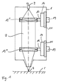
図1に図示されているように、本発明によるレーザー加工ヘッドは、ハウジング1を有しており、ハウジング1を通って、レーザービーム2が導かれる。光ファイバー3から現れるレーザービーム2を成形するために、たとえば、第1のオプティクス15’および第2のオプティクス15”が設けられており、第1のオプティクス15’は、コリメーターオプティクスとして形成されており、第2のオプティクス15”は、集束オプティクスとして、レーザービーム2とワークピース5との間の相互作用領域4の中へレーザービーム2を集束させる。オプティクス15’,15”の変位可能な装着に関して、オプティクス15’,15”は、ホルダー16を介してベルトドライブのキャリッジ14にそれぞれ固定されており、キャリッジ14は、モーター19によって駆動され得、装着部11の上で変位可能にガイドされる。装着部11は、図1に図示されているように、レーザー加工ヘッドのハウジング1の中に直接的に固定され得る。しかし、図2に示されているように、スライドインユニット10の上に装着部11を設けることも可能であり、スライドインユニット10は、レーザー加工ヘッドの中へ挿入され得る。
As shown in FIG. 1, the laser processing head according to the present invention has a
しかし、図1に示されているコリメーターオプティクスおよび集束オプティクスの代わりに、ズームオプティクスが、ビームシェイピングのために使用され得、ズームオプティクスによって、焦点位置だけでなく、焦点距離も変化させられ得る。 However, instead of the collimator and focusing optics shown in FIG. 1, zoom optics can be used for beam shaping, and the zoom optics can change not only the focal position but also the focal length.
図2に図示されているように、レーザー加工ヘッドの中へ挿入され得るスライドインユニット10は、装着部11を有しており、装着部11は、レーザー加工ヘッドのハウジング1に固定されている保持プレートとして形成されている。装着部11の上に設けられているのは、キャリッジ14のためのガイドレール12であり、キャリッジ14の上に、オプティクス15が保持されている。オプティクス15は、述べられているように、拡大およびコリメーションのための、すなわち、拡大された平行なレーザービームを作り出すためのコリメーターオプティクスであるか、または、切断、溶接、はんだ付け、もしくは粉末塗布溶接(powder application welding)などのために、加工されることとなるワークピース5の上にレーザービーム2を集束させる集束オプティクスであることが可能である。図1および図2に概略的に示されているように、オプティクス15は、ホルダー16を介してキャリッジ14に固定されており、キャリッジ14は、たとえば、保持スリーブなどとして形成され得る。キャリッジ14は、第1および第2のキャリッジレール17,18を有しており、第1および第2のキャリッジレール17,18は、装着部11の上のそれぞれのガイドレール12の上でガイドされており、また、装着部11の上の固定された場所に配置され、かつ、モーター19によって駆動されるベルトドラム20が、キャリッジ14を通って妨げられずに突出することができるように、第1および第2のキャリッジレール17,18が形成されており、ベルトドラム20およびキャリッジ14が邪魔し合わないようになっている。キャリッジレールのうちの1つ(図示されている例示的な実施形態では、第1のキャリッジレール17)に適合させられているのは、第1および第2のベルトホルダー21,22であり、第1および第2のベルト23,24が、それらの一方の端部によって、第1および第2のベルトホルダー21,22に固定されており、一方、それらのそれぞれの他の端部は、ベルトドラム20の周りに巻き付けられ、ベルトドラム20に固定されている。より正確には、第1のベルト23は、その一方の端部によって、ベルトホルダー21を介して、キャリッジ14の一方の端部(図1において、上側端部)に固定されており、一方、それは、その下側端部によって、時計回り方向にベルトドラム20の周りに巻き付けられ、ベルトドラム20に固定されている。第2のベルトは、2つの第2のベルト24として形成されており、第2のベルトは、図面の中のその下側端部において、ベルトホルダー22を介してキャリッジ14の他方の端部に接続されており、一方、その上側端部、すなわち、2つの第2のベルト24の上側端部は、反時計回り方向にドラム20の周りに導かれ、ドラム20に固定されている。第1および第2のベルト23,24は、2つの第2のベルト24が第1のベルト23の両側に存在するように、互いに隣同士に配置されている。ここでは、第1および第2のベルト23,24は、共同でベルトループを形成しており、それは、ドラム20の周りに導かれている。
As shown in FIG. 2, the slide-in
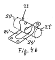
図4aに示されているように、第1のベルトおよび第2のベルトの代わりに、ワンピースのベルト33の第1のベルトセクション23’および2つの第2のベルトセクション24’が使用され得る。第1および第2のベルトセクション23’,24’は、ベルト33の中間で出会い、フォーク状のセクション34を形成しており、フォーク状のセクション34によって、図4bに示されているように、ベルト33がドラム20に固定されている。
As shown in FIG. 4a, instead of a first belt and a second belt, a first belt section 23 'and two second belt sections 24' of a one-
ベルトドライブのためのベルト23,24;33、すなわち、ドラム20の駆動力をキャリッジ14に伝達する可撓性の駆動手段は、50よりも大きい、好ましくは80よりも大きい、厚さに対する幅の比率を有している。ここで、ベルトは、スチール、好ましくは、ばね鋼からなり、0.1mmから0.01mmの範囲にある厚さ、好ましくは、0.08mmから0.02mmの範囲にある厚さ、とりわけ、おおよそ0.05mmの厚さを有している。
The
ベルトドラム半径に対するベルト厚さの比率が、0.05未満、好ましくは、0.03未満、とりわけ、0.01未満となるように、ベルト厚さおよびドラム直径がそれぞれ選ばれるべきである。たとえば、6mmのドラム半径に対応する、12mmのドラム直径が仮定される場合には、0.05mmのベルト厚さのケースでは、0.0083の曲げ半径に対するベルト厚さの比率という結果になる。 The belt thickness and drum diameter should each be chosen such that the ratio of belt thickness to belt drum radius is less than 0.05, preferably less than 0.03, in particular less than 0.01. For example, if a drum diameter of 12 mm, corresponding to a drum radius of 6 mm, is assumed, a belt thickness case of 0.05 mm results in a ratio of belt thickness to bend radius of 0.0083.
次いで、ドラムが、モーター19(それは、たとえば、ブラシレスDCモーターまたはステッピングモーターであることが可能である)によって、図2における時計回り方向に回転させられる場合には、第1のベルト23または第1のベルトセクション23’が巻き上げられ、一方、第2のベルト、すなわち、第2のベルト24または第2のベルトセクション24’が巻き戻され、キャリッジ14が図面の中で下向きに移動するようになっている。逆に、ベルトドラム20が反時計回り方向に回転する場合には、キャリッジ14は、上向きに移動させられることとなる。
Then, if the drum is rotated in the clockwise direction in FIG. 2 by the motor 19 (which can be, for example, a brushless DC motor or a stepping motor), the
ここで、オプティクス15の位置は、具体的には図示されていないリニアスケールによって測定される。対応する位置信号が、モーターコントローラーの上に渡され、それは、オプティクス15が所望のポイントに位置決めされることを確実にする。
Here, the position of the
モーター19は、そのトルクが、移動させられることとなる質量にベルトドラム20の半径を乗じたものよりも大きくなるように、設計されるべきである。次いで、外側から作用する力が、最大で重力の6倍になる加速度によってもたらされる場合に、そのようなモーター19は、オプティクス15をそれらの所望の位置に維持することも可能である。加速度の方向に応じて、ベルトドライブによって移動させられることとなる質量の重量が、追加的に作用する。
The
ベルトドライブの使用の結果として、オプティクス15は、したがって、スライドインユニット10の装着部11に対して、それらの光軸Aの方向に、ガイドレール12の間で往復して変位させられ得、所望の方式で、レーザー加工ヘッドの中のそれらの位置を調節するようになっている。コリメーターレンズのケースでは、レーザー光を供給する光ファイバーの出口表面がコリメーターオプティクスの現在の焦点と一致するように、オプティクス15が変位させられ、無限遠の出口表面をイメージングするようになっており、したがって、拡大された平行なレーザービームを得るようになっている。集束レンズのケースでは、レーザー焦点がワークピース表面に関連して所望の位置を有するように、オプティクス15が変位させられる。レンズの加温に起因して焦点の変位が起こる場合には、とりわけ、集束オプティクスのケースでは、オプティクス15は、実質的に中断される必要のある作業プロセスなしに、モーター19によって駆動されるベルトドライブを介してトラッキングされ得る。
As a result of the use of the belt drive, the
本発明にしたがって使用されるベルトドライブのかなりの利点は、曲げ半径に対する可撓性のドライブ厚さ(すなわち、ベルトの厚さ)の比率がより小さくさせられ、したがって、改善させられ得るということである。したがって、巻き付けおよび巻き戻しの結果として、張力下でベルトのローディングを低減させることも可能である。ケーブルと同様の摩滅メカニズムはベルトの中で起こらないので、レーザー加工ヘッドの中のレンズの汚染のリスクも存在しない。そのうえ、事実上摩耗のない、転がり摩擦だけでなく滑り摩擦の種類のものが、ベルトとベルトドラムとの間に起こらないということが重要である。 A significant advantage of the belt drive used in accordance with the present invention is that the ratio of flexible drive thickness (ie, belt thickness) to bending radius can be made smaller and therefore improved. is there. It is therefore possible to reduce the loading of the belt under tension as a result of winding and unwinding. Since a wear mechanism similar to a cable does not occur in the belt, there is no risk of lens contamination in the laser processing head. Moreover, it is important that no friction, not just rolling friction but also sliding friction types occur between the belt and the belt drum.
Claims (12)
前記レーザー加工ヘッドは、
装着部(11)と、
前記レーザービームの長手方向に変位させられ得るように、前記装着部(11)の上に装着されているビームシェイピングオプティクス(15)と、
前記オプティクス(15)を変位させるためのベルトドライブと、
を有しており、
前記ベルトドライブは、ベルトドラム(20)を有しており、
前記ベルトドラム(20)は、前記装着部(11)の上に回転可能に装着されており、
前記ベルトドラム(20)は、モーター(19)によって駆動可能で、ベルトドラム半径に対するベルト厚さの比率が、0.05未満である、
ことを特徴とする、レーザー加工ヘッド。 A laser processing head for processing a workpiece with a laser beam,
The laser processing head is
A mounting portion (11);
Beam shaping optics (15) mounted on the mounting portion (11) so that it can be displaced in the longitudinal direction of the laser beam;
A belt drive for displacing the optics (15);
Have
The belt drive has a belt drum (20),
The belt drum (20) is rotatably mounted on the mounting portion (11),
The belt drum (20) can be driven by a motor (19), and the ratio of the belt thickness to the belt drum radius is less than 0.05,
A laser processing head characterized by that.
前記ベルトドラム半径に対するベルト厚さの比率が、0.03未満であることを特徴とする、レーザー加工ヘッド。 The laser processing head according to claim 1 or 2,
Wherein the ratio of the belt thickness to belt drum radius, characterized in that it is a less than 0.03, the laser processing head.
− 前記オプティクス(15)は、キャリッジの上に保持されており、前記キャリッジは、それが前記レーザービームの前記長手方向に変位させられ得るように、前記装着部(11)の上に装着されており、前記キャリッジは、移動の方向に互いから間隔を離して配置された2つの端部を有しており、
− 第1のベルト(23)は、その一方の端部によって、前記キャリッジ(14)の一方の端部に固定されており、その他方の端部によって、前記ベルトドラム(20)の周りに巻き付けられ、前記ベルトドラム(20)に固定されており、第2のベルト(24)は、その一方の端部によって、前記キャリッジ(14)の他方の端部に固定されており、その他方の端部によって、前記ベルトドラム(20)の周りに巻き付けられ、前記ベルトドラム(20)に固定されていることを特徴とする、レーザー加工ヘッド。 The laser processing head according to any one of claims 1 to 3,
The optics (15) is held on a carriage, the carriage being mounted on the mounting part (11) so that it can be displaced in the longitudinal direction of the laser beam; The carriage has two ends that are spaced apart from each other in the direction of movement;
The first belt (23) is fastened to one end of the carriage (14) by one end and wound around the belt drum (20) by the other end; The second belt (24) is fixed to the other end of the carriage (14) by one end thereof and the other end is fixed to the belt drum (20). The laser processing head according to claim 1, wherein the laser processing head is wound around the belt drum (20) and fixed to the belt drum (20).
Applications Claiming Priority (3)
| Application Number | Priority Date | Filing Date | Title |
|---|---|---|---|
| DE102014101477.4A DE102014101477A1 (en) | 2014-02-06 | 2014-02-06 | Laser processing head |
| DE102014101477.4 | 2014-02-06 | ||
| PCT/EP2015/052456 WO2015118088A1 (en) | 2014-02-06 | 2015-02-05 | Laser machining head comprising a belt drive for moving an optics |
Publications (2)
| Publication Number | Publication Date |
|---|---|
| JP2017507784A JP2017507784A (en) | 2017-03-23 |
| JP6153672B2 true JP6153672B2 (en) | 2017-06-28 |
Family
ID=52464384
Family Applications (1)
| Application Number | Title | Priority Date | Filing Date |
|---|---|---|---|
| JP2016550572A Active JP6153672B2 (en) | 2014-02-06 | 2015-02-05 | Laser processing head including belt drive for moving optics |
Country Status (9)
| Country | Link |
|---|---|
| US (1) | US10150180B2 (en) |
| EP (1) | EP3068575B1 (en) |
| JP (1) | JP6153672B2 (en) |
| KR (1) | KR101788213B1 (en) |
| CN (1) | CN105980097B (en) |
| DE (1) | DE102014101477A1 (en) |
| PL (1) | PL3068575T3 (en) |
| RU (1) | RU2661686C1 (en) |
| WO (1) | WO2015118088A1 (en) |
Families Citing this family (10)
| Publication number | Priority date | Publication date | Assignee | Title |
|---|---|---|---|---|
| DE102016112176B4 (en) | 2016-07-04 | 2021-08-12 | Precitec Gmbh & Co. Kg | Device for the selective introduction of optics into a laser beam of a laser processing head and laser processing head with the same |
| CN106271045A (en) * | 2016-09-05 | 2017-01-04 | 苏州大学 | A kind of automatic focusing adjustor for laser processing, laser process equipment and focus adjustment method |
| EP3565687B1 (en) | 2017-01-05 | 2023-08-09 | Volkswagen Aktiengesellschaft | Laser tool with a focus adjustment unit |
| DE102017200080A1 (en) * | 2017-01-05 | 2018-07-05 | Volkswagen Aktiengesellschaft | Hollow shaft and non-rotating lens laser tool |
| DE102017107282B4 (en) * | 2017-04-05 | 2021-02-25 | Precitec Gmbh & Co. Kg | Cartesian positioning device and laser processing head with the same |
| DE102017107402B4 (en) | 2017-04-06 | 2019-05-29 | Precitec Gmbh & Co. Kg | Method and device for controlling a focal position of a working laser beam and laser processing head with such a device |
| DE102018116998A1 (en) * | 2018-07-13 | 2020-01-16 | Jenoptik Automatisierungstechnik Gmbh | Sensor device for scanning laser processing of a workpiece by means of a laser beam deflected around a pivot point |
| DE102021101953B3 (en) | 2021-01-28 | 2022-07-14 | Precitec Gmbh & Co. Kg | Transport lock for a movable optics of a laser processing head |
| DE102021123617A1 (en) | 2021-09-13 | 2023-03-16 | Precitec Gmbh & Co. Kg | Laser processing head with glue trap |
| DE102022102664B3 (en) | 2022-02-04 | 2023-08-10 | Precitec Gmbh & Co. Kg | Laser processing head with hermetically encapsulated movable optics |
Family Cites Families (22)
| Publication number | Priority date | Publication date | Assignee | Title |
|---|---|---|---|---|
| US2706913A (en) | 1953-06-01 | 1955-04-26 | Trossi Domenico | Mechanical movement for converting translatory motion into rotary motion, and vice versa, especially for precision instruments |
| US4366722A (en) * | 1980-06-26 | 1983-01-04 | International Memories, Incorporated | Drive connection between linear actuator and rotatable drive shaft of reversible motor |
| US4366772A (en) * | 1981-03-30 | 1983-01-04 | Babson Bros. Co. | Stall cock and pulsator for a milker |
| JPH0785124B2 (en) * | 1986-07-14 | 1995-09-13 | オリンパス光学工業株式会社 | Automatic focus adjustment device |
| JPS63123589A (en) * | 1986-11-11 | 1988-05-27 | Mitsubishi Electric Corp | Laser beam machine |
| SU1527602A1 (en) | 1988-03-09 | 1989-12-07 | Институт Технической Кибернетики Ан Бсср | Mechanism for automatic focusing of lens |
| EP0437204B1 (en) * | 1990-01-11 | 1994-09-14 | Canon Kabushiki Kaisha | Lateral shift control for endless belt and fixing apparatus using same |
| SU1757827A1 (en) | 1990-12-25 | 1992-08-30 | Научно-исследовательский центр по технологическим лазерам АН СССР | Apparatus for working by laser |
| JP2804206B2 (en) * | 1992-09-22 | 1998-09-24 | 三菱電機株式会社 | Laser processing head |
| US5546238A (en) * | 1993-08-11 | 1996-08-13 | Hughes Aircraft Company | Zoom lens having high speed multi-lens drive |
| DE29507189U1 (en) | 1995-04-28 | 1995-06-29 | Precitec GmbH, 76571 Gaggenau | Connection head for processing a workpiece using a laser beam |
| DE19622413C2 (en) | 1996-06-04 | 1998-07-16 | Precitec Gmbh | Linear drive, in particular for connection heads of laser processing systems |
| DE19628857A1 (en) * | 1996-07-17 | 1998-01-29 | Precitec Gmbh | Head for processing workpieces using laser beam |
| JP2005004113A (en) * | 2003-06-16 | 2005-01-06 | Oputeru:Kk | Optical fiber coupler manufacturing method |
| JP2008105064A (en) * | 2006-10-26 | 2008-05-08 | Disco Abrasive Syst Ltd | Laser beam machining apparatus |
| US8381902B2 (en) * | 2008-05-28 | 2013-02-26 | Kobe Steel, Ltd. | Belt meandering preventing device and belt meandering preventing method for running test device |
| RU2386523C1 (en) * | 2008-12-25 | 2010-04-20 | Открытое акционерное общество Национальный институт авиационных технологий (ОАО НИАТ) | Device for cutting of volume parts with fibre laser |
| JP5172041B2 (en) * | 2009-07-20 | 2013-03-27 | プレシテック カーゲー | Laser machining head and method for compensating for changes in the focal position of the laser machining head |
| DE202009012924U1 (en) * | 2009-09-25 | 2010-01-14 | Precitec Kg | Insert for holding an optic in a laser processing head and a laser processing head |
| DE102010020183B4 (en) * | 2010-05-11 | 2013-07-11 | Precitec Kg | Laser cutting head and method for cutting a workpiece by means of a laser cutting head |
| KR101481857B1 (en) * | 2011-09-30 | 2015-01-13 | 코오롱인더스트리 주식회사 | Seamless belt |
| JP7085124B2 (en) * | 2018-04-27 | 2022-06-16 | トヨタ自動車株式会社 | Sulfide solid-state battery and sulfide solid-state battery system equipped with it |
-
2014
- 2014-02-06 DE DE102014101477.4A patent/DE102014101477A1/en not_active Withdrawn
-
2015
- 2015-02-05 KR KR1020167020011A patent/KR101788213B1/en active IP Right Grant
- 2015-02-05 WO PCT/EP2015/052456 patent/WO2015118088A1/en active Application Filing
- 2015-02-05 CN CN201580007244.5A patent/CN105980097B/en active Active
- 2015-02-05 PL PL15703563T patent/PL3068575T3/en unknown
- 2015-02-05 EP EP15703563.5A patent/EP3068575B1/en active Active
- 2015-02-05 JP JP2016550572A patent/JP6153672B2/en active Active
- 2015-02-05 RU RU2016125482A patent/RU2661686C1/en active
- 2015-02-05 US US15/111,107 patent/US10150180B2/en active Active
Also Published As
| Publication number | Publication date |
|---|---|
| KR20160093733A (en) | 2016-08-08 |
| CN105980097B (en) | 2018-07-31 |
| DE102014101477A1 (en) | 2015-08-06 |
| EP3068575A1 (en) | 2016-09-21 |
| CN105980097A (en) | 2016-09-28 |
| KR101788213B1 (en) | 2017-10-19 |
| EP3068575B1 (en) | 2017-11-08 |
| US20160339541A1 (en) | 2016-11-24 |
| PL3068575T3 (en) | 2018-04-30 |
| RU2661686C1 (en) | 2018-07-19 |
| US10150180B2 (en) | 2018-12-11 |
| JP2017507784A (en) | 2017-03-23 |
| RU2016125482A (en) | 2018-01-09 |
| WO2015118088A1 (en) | 2015-08-13 |
Similar Documents
| Publication | Publication Date | Title |
|---|---|---|
| JP6153672B2 (en) | Laser processing head including belt drive for moving optics | |
| JP5102632B2 (en) | Laser processing machine | |
| JP5372598B2 (en) | Processing method and processing system | |
| JP5007706B2 (en) | Work cutting method | |
| EP3350638B1 (en) | Wiping system | |
| JP2008504131A (en) | Pressure welding machine and pressure welding method | |
| JP2010264562A (en) | Method and system for machining | |
| JP2005224864A (en) | Machine tool for processing workpiece by using laser beam | |
| JP5155191B2 (en) | Exposure equipment | |
| CA3054012A1 (en) | Machine for the working of tubes provided with an optical sensor for measuring the forward displacement of the tube being worked and/or the rotational displacement of the same about the longitudinal axis thereof | |
| JP7113629B2 (en) | Cable transfer device | |
| EP1600242A2 (en) | Reflector-mirror drive shaft controller for laser beam machine | |
| JP4520918B2 (en) | Slit width adjusting device and microscope laser repair device having the same | |
| KR20190095885A (en) | Nondestructive detecting method | |
| JP4409354B2 (en) | Laser processing machine | |
| JP5039395B2 (en) | Processing system | |
| CN220427134U (en) | Laser cutting head capable of automatically focusing along with cutting surface | |
| JP2000024788A (en) | Laser beam machining device | |
| JP2022074313A (en) | Laser processing device | |
| JP7171633B2 (en) | Method and apparatus for acquiring 3D data of a 3D surface of a workpiece | |
| JPH09197286A (en) | Microscope device | |
| JP6562216B2 (en) | Wire saw equipment | |
| JP2016206595A (en) | Drive device, and lens unit using the same | |
| TH10409C3 (en) | Pipe Notch Cutter for Welding Practice | |
| TH10409A3 (en) | Pipe Notch Cutter for Welding Practice |
Legal Events
| Date | Code | Title | Description |
|---|---|---|---|
| A975 | Report on accelerated examination |
Free format text: JAPANESE INTERMEDIATE CODE: A971005 Effective date: 20170105 |
|
| A131 | Notification of reasons for refusal |
Free format text: JAPANESE INTERMEDIATE CODE: A131 Effective date: 20170117 |
|
| A521 | Request for written amendment filed |
Free format text: JAPANESE INTERMEDIATE CODE: A523 Effective date: 20170412 |
|
| TRDD | Decision of grant or rejection written | ||
| A01 | Written decision to grant a patent or to grant a registration (utility model) |
Free format text: JAPANESE INTERMEDIATE CODE: A01 Effective date: 20170509 |
|
| A61 | First payment of annual fees (during grant procedure) |
Free format text: JAPANESE INTERMEDIATE CODE: A61 Effective date: 20170530 |
|
| R150 | Certificate of patent or registration of utility model |
Ref document number: 6153672 Country of ref document: JP Free format text: JAPANESE INTERMEDIATE CODE: R150 |
|
| R250 | Receipt of annual fees |
Free format text: JAPANESE INTERMEDIATE CODE: R250 |
|
| R250 | Receipt of annual fees |
Free format text: JAPANESE INTERMEDIATE CODE: R250 |
|
| R250 | Receipt of annual fees |
Free format text: JAPANESE INTERMEDIATE CODE: R250 |
|
| R250 | Receipt of annual fees |
Free format text: JAPANESE INTERMEDIATE CODE: R250 |
|
| R250 | Receipt of annual fees |
Free format text: JAPANESE INTERMEDIATE CODE: R250 |