JP6152552B2 - Glass forming equipment - Google Patents
Glass forming equipment Download PDFInfo
- Publication number
- JP6152552B2 JP6152552B2 JP2015545206A JP2015545206A JP6152552B2 JP 6152552 B2 JP6152552 B2 JP 6152552B2 JP 2015545206 A JP2015545206 A JP 2015545206A JP 2015545206 A JP2015545206 A JP 2015545206A JP 6152552 B2 JP6152552 B2 JP 6152552B2
- Authority
- JP
- Japan
- Prior art keywords
- tray
- glass
- peripheral wall
- forming apparatus
- molding
- Prior art date
- Legal status (The legal status is an assumption and is not a legal conclusion. Google has not performed a legal analysis and makes no representation as to the accuracy of the status listed.)
- Active
Links
Images


Classifications
-
- C—CHEMISTRY; METALLURGY
- C03—GLASS; MINERAL OR SLAG WOOL
- C03B—MANUFACTURE, SHAPING, OR SUPPLEMENTARY PROCESSES
- C03B17/00—Forming molten glass by flowing-out, pushing-out, extruding or drawing downwardly or laterally from forming slits or by overflowing over lips
- C03B17/06—Forming glass sheets
- C03B17/064—Forming glass sheets by the overflow downdraw fusion process; Isopipes therefor
Description
本出願は、2012年11月29日に出願された米国特許出願第13/689,287号の恩典を主張し、これらの優先権を主張する。上記出願の明細書の内容は本明細書に参照として含まれる。 This application claims the benefit of, and claims priority to, US patent application Ser. No. 13 / 689,287, filed Nov. 29, 2012. The contents of the specification of the above application are included herein by reference.
本発明はガラス成形装置に関し、特に詳細には、溶融ガラスを成形部材に沿って下方に流下させてシート状に成形するガラス成形装置に関するものである。 The present invention relates to a glass forming apparatus, and more particularly to a glass forming apparatus that forms molten glass into a sheet shape by flowing down along a forming member.
従来、シート状のガラスを成形する装置の一つとして、いわゆるフュージョンドロー装置が知られている。このフュージョンドロー装置は、溶融ガラスを成形部材に沿って下方に流下させて所定厚さのガラスリボンを製造するものである。このガラスリボンを切断して、一枚ずつのガラス板が得られる。 Conventionally, a so-called fusion draw apparatus is known as one of apparatuses for forming sheet-like glass. This fusion draw apparatus manufactures a glass ribbon having a predetermined thickness by causing molten glass to flow downward along a molding member. The glass ribbon is cut to obtain one glass plate at a time.
この種のガラス成形装置としてより詳しくは、溶融ガラスをシート状に成形するための内部空間を画成するようにこの空間の側方周囲を閉じ、下方に下部開口を有する第一周壁と、上記成形用内部空間に配置され、溶融ガラスを下方に流下させてガラスリボンに成形する上記成形部材等からなる成形手段と、上記第一周壁に対して間隙を置いて下方に配置され、ガラスリボンが通過する上部開口を有するとともに、該ガラスリボンを受け入れる内部空間を画成するようにこの空間の側方周囲を閉じる第二周壁と、この第二周壁内に配置され、成形手段を経たガラスリボンを挟み付けて下方に引き下ろすローラ対とを備えてなるものが知られている。
In more detail as this type of glass forming apparatus, the first peripheral wall having a lower opening at the bottom and closing the side periphery of the space so as to define an internal space for forming molten glass into a sheet shape, The molding means, which is disposed in the molding internal space, and which is made of the molding member or the like for forming the glass ribbon by flowing down the molten glass downward, is disposed below the first peripheral wall with a gap between the molding means and the glass. A second peripheral wall having an upper opening through which the ribbon passes and closing a side periphery of the space so as to define an internal space for receiving the glass ribbon, and glass that has been formed through the forming means and disposed in the second
ところで、上述のような構成を有するガラス成形装置においては、溶融ガラスが外部から供給される第一周壁内において、溶融ガラスからの揮発物が凝集し、それが雫状になって第一周壁の内面を伝い、落下することがある。このような凝集ガラス成分が、成形中のガラスリボンと前記ローラ対との間に落ちて両者に挟まれると、成形不良やガラスリボンの割れ等の問題を招く。 By the way, in the glass forming apparatus having the above-described configuration, in the first peripheral wall to which the molten glass is supplied from the outside, the volatiles from the molten glass aggregate and form a bowl-like shape. May fall through the inner surface of the wall. If such agglomerated glass component falls between the glass ribbon being molded and the pair of rollers and is sandwiched between the two, problems such as molding defects and cracking of the glass ribbon are caused.
ガラス成形装置においては一般に、上記ローラ対よりも上方に第一周壁内部の温度を調整するための仕切り板が設置されており、第一周壁内面を伝った雫状の凝集ガラスが仕切り板に到達し、その後仕切り板表面を伝って落下することがある。この仕切り板表面を伝う凝集ガラスは、第一周壁と第二周壁との間の間隙から棒状の清掃部材を挿入して、その清掃部材により掻き落とすことが可能である。 In the glass forming apparatus, generally, a partition plate for adjusting the temperature inside the first peripheral wall is installed above the pair of rollers, and the bowl-shaped aggregated glass that has passed along the inner surface of the first peripheral wall is the partition plate. May then fall along the surface of the partition plate. The agglomerated glass transmitted along the surface of the partition plate can be scraped off by inserting a rod-shaped cleaning member through the gap between the first peripheral wall and the second peripheral wall.
しかし、狭い間隙に清掃部材を挿入して操作する作業は極めて作業能率が悪いものであり、また、困難な作業をしているうちに、清掃部材により、もしくは清掃中に雫が落下することにより、新たな成形不良、割れが発生する場合がある。このような雫の落下は予測不可能であり、従来の作業ではこれを常に監視する必要があった。 However, the operation of inserting a cleaning member into a narrow gap is extremely inefficient, and it is possible that the scissors fall during the cleaning or during the cleaning. New molding defects and cracks may occur. Such a drop of the kite is unpredictable, and it has been necessary to constantly monitor this in the conventional work.
本発明は上記の事情に鑑みてなされたものであり、凝集ガラス成分を作業性良く回収して、この凝集ガラス成分による成形不良やガラスリボンの割れ等の問題を防止することができるガラス成形装置を提供することを目的とする。 The present invention has been made in view of the above circumstances, and is capable of recovering the aggregated glass component with good workability and preventing problems such as molding defects due to the aggregated glass component and breakage of the glass ribbon. The purpose is to provide.
一つの実施形態による第1のガラス成形装置は、
溶融ガラスをガラスリボンに成形するための成形用内部空間を画成するようにこの空間の側方周囲を閉じ、下方に下部開口を有する第一周壁と、
前記成形用内部空間に配置され、溶融ガラスを下方に流下させてガラスリボンに成形する成形手段と、
前記第一周壁に対して間隙を置いて下方に配置され、前記ガラスリボンが通過する上部開口を有するとともに、該ガラスリボンを受け入れる内部空間を画成するようにこの空間の側方周囲を閉じる第二周壁と、
この第二周壁内に配置され、前記成形手段を経たガラスリボンを挟み付けて下方に引き下ろすローラ対と、
基端が第一周壁の内面に固定され、先端が前記基端よりも下方に位置する形状を有して、前記成形用内部空間の温度を調整するための仕切り板とを備えている。そしてこのガラス成形装置はさらに、
一部が開いた箱型の形状を有するトレイと、
このトレイを前記間隙に挿入、かつそこから退出可能とし、挿入した際に、トレイの開いた部分が前記仕切り板の先端の下側において、該先端に沿って延びる状態に保持するトレイ保持機構とを有していてもよい。
The first glass forming apparatus according to one embodiment includes:
A first peripheral wall having a lower side opening and a side periphery thereof closed so as to define a molding inner space for molding molten glass into a glass ribbon;
A molding means that is disposed in the molding internal space and flows down the molten glass to form a glass ribbon,
A space is provided below the first peripheral wall and has an upper opening through which the glass ribbon passes, and the side periphery of the space is closed so as to define an internal space for receiving the glass ribbon. The second wall,
A roller pair disposed within the second peripheral wall and sandwiching the glass ribbon that has undergone the forming means and pulled down;
The base end is fixed to the inner surface of the first peripheral wall, and the front end has a shape positioned below the base end, and includes a partition plate for adjusting the temperature of the molding internal space. And this glass forming device
A tray with a partially open box shape;
A tray holding mechanism that allows the tray to be inserted into and removed from the gap, and that when the tray is inserted, the tray open portion is held below the front end of the partition plate so as to extend along the front end. You may have.
なお、上記トレイ保持機構は、例えば第二周壁の上端面を含む部分から構成されるのが望ましい。 The tray holding mechanism is preferably composed of a portion including the upper end surface of the second peripheral wall, for example.
また、別の実施形態による第2のガラス成形装置は、
溶融ガラスをガラスリボンに成形するための成形用内部空間を画成するようにこの空間の側方周囲を閉じ、下方に下部開口を有する第一周壁と、
前記成形用内部空間に配置され、溶融ガラスを下方に流下させてガラスリボンに成形する成形手段と、
前記第一周壁に対して間隙を置いて下方に配置され、前記ガラスリボンが通過する上部開口を有するとともに、該ガラスリボンを受け入れる内部空間を画成するようにこの空間の側方周囲を閉じる第二周壁と、
この第二周壁内に配置され、前記成形手段を経たガラスリボンを挟み付けて下方に引き下ろすローラ対と、
基端が第一周壁の内面に固定され、先端が前記基端よりも下方に位置する形状を有して、前記成形用内部空間の温度を調整するための仕切り板とを備えたものであり、
そしてこのガラス成形装置はさらに、
前記ローラ対よりも上の位置において前記第二周壁の一部に形成されて、その内部と外部とを連通させる切欠と、
一部が開いた箱型の形状を有するトレイと、
前記トレイを、その開いた部分が横方向を向く状態で前記切欠から第二周壁内に進入、かつそこから退出可能とし、進入した後、前記開いた部分が上方向を向くまでトレイが回転することを許容し、この回転後に、トレイが前記仕切り板の先端の下側において、該先端に沿って延びる状態に該トレイを保持するトレイ保持機構とを有していてもよい。なお上記トレイ保持機構は、トレイの一端部を固定して仕切り板の先端と平行な方向に延びるロッドと、このロッドを回転自在に保持する部分および、この部分から上下に延びてトレイを通過させる部分とからなる貫通孔を有する架台とを備えたものであることが望ましく、さらには上記ロッドを回転させるハンドルも備えていることがより望ましい。
Moreover, the 2nd glass shaping | molding apparatus by another embodiment is as follows.
A first peripheral wall having a lower side opening and a side periphery thereof closed so as to define a molding inner space for molding molten glass into a glass ribbon;
A molding means that is disposed in the molding internal space and flows down the molten glass to form a glass ribbon,
A space is provided below the first peripheral wall and has an upper opening through which the glass ribbon passes, and the side periphery of the space is closed so as to define an internal space for receiving the glass ribbon. The second wall,
A roller pair disposed within the second peripheral wall and sandwiching the glass ribbon that has undergone the forming means and pulled down;
The base end is fixed to the inner surface of the first peripheral wall, the tip has a shape positioned below the base end, and includes a partition plate for adjusting the temperature of the molding internal space. Yes,
And this glass forming device
A notch that is formed in a part of the second peripheral wall at a position above the pair of rollers and that communicates the inside and the outside;
A tray with a partially open box shape;
The tray is allowed to enter the second peripheral wall from the notch with the opened portion facing in the lateral direction and can be withdrawn therefrom, and after entering, the tray rotates until the opened portion faces upward. The tray may have a tray holding mechanism that holds the tray in a state of extending along the tip below the tip of the partition plate after the rotation. The tray holding mechanism fixes the one end of the tray and extends in a direction parallel to the front end of the partition plate, a portion that rotatably holds the rod, and a portion that extends vertically from this portion and passes the tray. It is desirable that the apparatus has a pedestal having a through-hole formed of a portion, and more preferably a handle for rotating the rod.
また、さらに別の実施形態による第3のガラス成形装置は、
溶融ガラスをガラスリボンに成形するための成形用内部空間を画成するようにこの空間の側方周囲を閉じ、下方に下部開口を有する第一周壁と、
前記成形用内部空間に配置され、溶融ガラスを下方に流下させてガラスリボンに成形する成形手段と、
前記第一周壁に対して間隙を置いて下方に配置され、前記ガラスリボンが通過する上部開口を有するとともに、該ガラスリボンを受け入れる内部空間を画成するようにこの空間の側方周囲を閉じる第二周壁と、
この第二周壁内に配置され、前記成形手段を経たガラスリボンを挟み付けて下方に引き下ろすローラ対と、
基端が第一周壁の内面に固定され、先端が前記基端よりも下方に位置する形状を有して、前記成形用内部空間の温度を調整するための仕切り板とを備えたものであり、
そしてこのガラス成形装置はさらに、
前記ローラ対よりも上の位置において第二周壁の一部に形成されて、その内部と外部とを連通させる切欠と、
一部が開いた箱型の形状を有するトレイと、
このトレイを前記切欠から第二周壁の内部に進入、かつそこから退出可能とし、回転した後に、トレイが前記仕切り板の先端の下側において、該先端に沿って延びる状態に該トレイを保持するトレイ保持機構とを有していてもよい。
In addition, the third glass forming apparatus according to still another embodiment
A first peripheral wall having a lower side opening and a side periphery thereof closed so as to define a molding inner space for molding molten glass into a glass ribbon;
A molding means that is disposed in the molding internal space and flows down the molten glass to form a glass ribbon,
A space is provided below the first peripheral wall and has an upper opening through which the glass ribbon passes, and the side periphery of the space is closed so as to define an internal space for receiving the glass ribbon. The second wall,
A roller pair disposed within the second peripheral wall and sandwiching the glass ribbon that has undergone the forming means and pulled down;
The base end is fixed to the inner surface of the first peripheral wall, the tip has a shape positioned below the base end, and includes a partition plate for adjusting the temperature of the molding internal space. Yes,
And this glass forming device
A notch that is formed in a part of the second peripheral wall at a position above the pair of rollers and communicates the inside and the outside;
A tray with a partially open box shape;
The tray can be moved into and out of the second peripheral wall from the notch, and after rotating, the tray is held in a state of extending along the tip under the tip of the partition plate. And a tray holding mechanism.
なお上記トレイ保持機構は、前記切欠の下端となる、第二周壁の上方を向いた面を含む部分から構成されるのが望ましい。 The tray holding mechanism is preferably composed of a portion including a surface facing the upper side of the second peripheral wall, which is the lower end of the notch.
前記トレイは、凹字状の断面形状を有するものとされるのが望ましい。また、トレイの開いた部分の長さが仕切り板の先端の横幅以上とされていることが望ましい。 The tray preferably has a concave cross-sectional shape. In addition, it is desirable that the length of the open portion of the tray is equal to or greater than the lateral width of the front end of the partition plate.
さらに前記仕切り板は、先端がガラスリボンの幅方向に延びる状態に形成されて、該ガラスリボンの両側にそれぞれ配置される一方、トレイが、2つの仕切り板に各々対応させて2個設けられていることが望ましい。 Further, the partition plate is formed in a state where the tip extends in the width direction of the glass ribbon, and is arranged on both sides of the glass ribbon, while two trays are provided corresponding to the two partition plates, respectively. It is desirable.
また本開示における実施形態は、フュージョンドローガラス成形装置に対して適用されることが望ましい。 In addition, the embodiment in the present disclosure is desirably applied to a fusion draw glass forming apparatus.
以上説明した実施形態のガラス成形装置はいずれも、ローラ対よりも上の位置で、一部が開いた箱型のトレイを、該トレイが仕切り板の先端の下側において、該先端に沿って延びる状態に保持可能としたものである。そこで、仕切り板の先端から落下した凝集ガラス成分はこのトレイに受け止められるようになる。こうして凝集ガラス成分がトレイに受け止められれば、凝集ガラス成分が成形中のガラスリボンとローラ対との間に落ちて両者に挟まれことがなくなるので、前述した成形不良やシート状ガラスの割れ等の問題が発生することを確実に防止可能となる。 In any of the glass forming apparatuses of the embodiments described above, a box-shaped tray that is partially open is positioned above the roller pair, and the tray is below the front end of the partition plate along the front end. It can be held in an extended state. Therefore, the aggregated glass component dropped from the tip of the partition plate can be received by this tray. If the agglomerated glass component is received by the tray in this way, the agglomerated glass component will not fall between the glass ribbon and the roller pair being molded and will not be sandwiched between the two. It is possible to reliably prevent problems from occurring.
そしてこのトレイは、例えば第一周壁と第二周壁との間の間隙から外に、あるいは第二周壁の内部から外に退出可能とされているので、該トレイに凝集ガラス成分が多く堆積したならばトレイを適宜退出させて、堆積した凝集ガラス成分を作業性良く簡単に回収することができる。 And this tray, for example, can be withdrawn from the gap between the first peripheral wall and the second peripheral wall or out of the second peripheral wall, so that a large amount of aggregated glass component is deposited on the tray. Then, the tray can be withdrawn as appropriate, and the aggregated glass component deposited can be easily recovered with good workability.
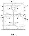
以下、本発明の実施形態について図面を参照して詳細に説明する。図1は、本発明の第1の実施形態によるガラス成形装置を示す一部破断正面図であり、図2および図3はそれぞれ、このガラス成形装置のガラス成形に関わる部分、凝集ガラス成分の回収に関わる部分を示す斜視図である。 Hereinafter, embodiments of the present invention will be described in detail with reference to the drawings. FIG. 1 is a partially broken front view showing a glass forming apparatus according to a first embodiment of the present invention, and FIGS. 2 and 3 respectively show a part related to glass forming of this glass forming apparatus and a collection of aggregated glass components. It is a perspective view which shows the part in connection with.
本実施形態のガラス成形装置はいわゆるフュージョンドロー装置であり、図1に示されるように基本的に、第一冷却部1と、その下方に配置された第二冷却部2とを有している。第一冷却部1は、第一周壁3の中に成形手段4を配置して構成されている。第一周壁3は断熱部材から形成されて、内部に、周囲4面が閉じられた成形用内部空間5を画成している。またこの第一周壁3は、成形用内部空間5の上方は閉じ、下方には下部開口3aを有している。一方第二冷却部2は、上記下部開口3aと整合する上部開口10aを有する第二周壁10を有している。この第二周壁10は、周囲4面と下面が閉じられた内部空間11を画成している。
The glass forming apparatus of the present embodiment is a so-called fusion draw apparatus, and basically includes a
上記第一周壁3および第二周壁10の内部はそれぞれ、図示外の加熱手段と温度調節手段により、各々所定の温度に維持されるようになっている。
The insides of the first
図2は、上記成形体4とその周辺部分を示している。図示の通り成形体4は、トラフ4aと、2つの合流側壁すなわち合流成形面4bとを有する、上部が開口した状態の槽である。上記トラフ4aには供給口6から、図示外の溶融ガラス源から溶融ガラス7が供給される。この溶融ガラス7はトラフ4aの上部側縁から溢れ出て、2つの分離した溶融ガラスの流れとして合流成形面4bに沿って流下する。これらの溶融ガラス7の流れは、合流成形面4bが交わる成形体4の下端で再結合し、清澄な外側表面を有するガラスリボン8となる。このガラスリボン8は、第一周壁3の下部開口3aを通り、第二冷却部2の第二周壁10内に配置された1対のプリングローラ9によって下方に牽引される。その後このガラスリボン8は、第二冷却部2内で十分な粘度および温度まで冷却された後に、所定サイズのシートに切断される。
FIG. 2 shows the molded body 4 and its peripheral portion. As shown in the figure, the molded body 4 is a tank having a
なお、成形体4の細部についての詳しい説明は省略するが、このような成形体を用いるフュージョンガラス製造プロセスについては、例えば米国特許第3,338,696号明細書等に詳しい記載があり、本発明においても、そこに記載されているような公知の製造技術を適宜採用することができる。 A detailed description of the details of the molded body 4 is omitted, but a fusion glass manufacturing process using such a molded body is described in detail in, for example, US Pat. No. 3,338,696, etc. Also in the invention, known manufacturing techniques as described therein can be appropriately employed.
ここで、この種のフュージョンドロー装置においては、成形用内部空間5において、溶融ガラス7からの揮発物が凝集し、それが雫状になって第一周壁3の内面を伝い、落下することがある。このような凝集ガラス成分が、成形中のガラスリボン8とプリングローラ9との間に落ちて両者に挟まれると、成形不良やガラスリボン8の割れ等の問題を招く。
Here, in this type of fusion draw apparatus, the volatiles from the molten glass 7 aggregate in the molding
以下、このような問題の発生を防止するための構成について説明する。第一周壁3の4面有る側壁のうち2つにはそれぞれ、成形用内部空間5の温度を調整するための仕切り板15の基端が固定されている。各仕切り板15は、その先端がガラスリボン8の幅方向に沿って延びる四角形に形成され、その先端が上記基端よりも下方に位置するように傾斜した状態に取り付けられている。またこの仕切り板15の幅は、ガラスリボン8の幅と同じか、あるいやそれよりもやや大きい程度とされている。なおこれらの仕切り板15は、傾斜角度が変わるように揺動自在な構造のものであってもよい。
Hereinafter, a configuration for preventing such a problem from occurring will be described. A base end of a
上記2枚の仕切り板15の各先端の下方位置には、後述するトレイ保持機構20に保持された2つのトレイ21が配設されるようになっている。各トレイ21は、細長い断面凹字型の部材の前後両端が閉じられた箱型とされ、上方の開いた部分の長さが、仕切り板15の先端の横幅以上とされたものである。これらのトレイ21は、第一周壁3と第二周壁10との間の間隙30に進入させて、上方の開いた部分がそれぞれ、仕切り板15の先端に沿ってそのやや下方に位置するように配される。
Two
そこで、上述した雫状の凝集ガラス成分が第一周壁3の内面から仕切り板15の上を伝い、その先端から落下すると、トレイ21内に落ちてそこに捕捉される。したがって、上記凝集ガラス成分が成形中のガラスリボン8とプリングローラ9との間に落ちて両者に挟まれることがなくなり、成形不良やガラスリボン8の割れといった問題の発生を確実に防止可能となる。
Therefore, when the above-mentioned bowl-shaped aggregated glass component travels on the
なおトレイ21は、耐熱性の高い材料、中でも例えばヘインズアロイ(登録商標)、SUS310、セラミック等、高温域で安定した性能を有する材料を使用して形成するのが望ましい。
The
またトレイ21は、上述のように凝集ガラス成分を受け止め可能になる使用位置と、上記間隙30から退出した位置との間で移動自在とされている。それにより、トレイ21に多くの凝集ガラス成分が堆積したならば、適宜トレイ21を間隙30から退出させ、その堆積した凝集ガラス成分を排除することが可能になっている。以下、図3も参照して、そのための構造について詳しく説明する。
In addition, the
図3は、2つのトレイ21を保持するトレイ保持機構20の一部を示している。ここに示される通りトレイ保持機構20は、2つのトレイ21の一端部を固定する固定部材24と、この固定部材24に取り付けられたハンドル25とを有している。本実施形態においては、作業者がハンドル25を持って2つのトレイ21を動かし、それらが第二周壁10の上端面10c(図1参照)の上の適切な位置に載置される。なお各トレイ21の先端部は、挿入された側の第二周壁10と反対側(つまり図1で奧方側)にある第二周壁10の上端面10cの上に保持される。
FIG. 3 shows a part of the
以上の通り本実施形態ではトレイ保持機構20が、トレイ21を下から受ける第二周壁10の上端面10cの一部分と、上記固定部材24およびハンドル25とから構成されている。
As described above, in the present embodiment, the
なお、上述のように固定部材24によって2つのトレイ21を連結することは必ずしも必要ではなく、トレイ21を1つずつ個別に操作するようにしても構わない。さらには、第二周壁10の上端面10cを含む部分にはトレイ21を保持させずに、周壁3、10の他に別途設けたトレイ保持機構にトレイ21を保持させても構わない。
Note that it is not always necessary to connect the two
なお図1および図2では、トレイ21を固定部材24に近い部分で切断して示し、それに続く固定部材24およびハンドル25は省いた状態で図示している。
In FIGS. 1 and 2, the
作業者は、2つのトレイ21の大部分を前記間隙30から外に(図3中の左方に)引き出すことができる。この状態にすれば、トレイ21の中に堆積した凝集ガラス成分をトレイ21から容易に取り除くことができる。
The operator can draw most of the two
なお本実施形態において、断面凹字状のトレイ21の上方が開いた部分の長さは、仕切り板15の先端の幅以上とされているが、例えば仕切り板15に、凝集ガラス成分を先端の一部のみに向けて案内するようなガイドが形成されている場合は、トレイ21の上方が開いた部分の長さを、仕切り板15の先端の上記一部から落下する凝集ガラス成分を受け止め得るだけの短いものとしても構わない。これは、後述する第2の実施形態においても同様である。
In the present embodiment, the length of the open portion of the
次に図4〜6を参照して、本発明の第2の実施形態について説明する。なおこれらの図4〜6において、図1〜3中の要素と同等の要素には同番号を付してあり、それらについての説明は特に必要のない限り省略する。 Next, a second embodiment of the present invention will be described with reference to FIGS. 4 to 6, the same elements as those in FIGS. 1 to 3 are denoted by the same reference numerals, and description thereof will be omitted unless particularly necessary.
図4は、本実施形態のガラス成形装置を示す一部破断正面図であり、図5はこのガラス成形装置の凝集ガラス成分の回収に関わる要部を示す斜視図であり、図6はこのガラス成形装置におけるトレイ21の動作を説明する概略図である。この第2実施形態の装置は、先に説明した第1実施形態の装置と比べると、基本的に、図5に示したトレイ保持機構40の部分が異なるものである。また、この第2実施形態の装置において、ガラス成形体は第1実施形態の装置におけるもの、つまり図2の構成と同じものが適用されている。
FIG. 4 is a partially broken front view showing the glass forming apparatus of the present embodiment, FIG. 5 is a perspective view showing a main part related to the collection of the agglomerated glass component of the glass forming apparatus, and FIG. It is the schematic explaining operation | movement of the
図5に示すトレイ保持機構40は、2つの貫通孔41aを有する架台41と、上記貫通孔41a内に挿通されて先端に各々トレイ21を固定した2本のロッド42と、これらのロッド42の細径とされた後端部を挿通、保持する円形の貫通孔(図示せず)を有するロッド保持板43と、各ロッド42の上記後端部に固定された2つの回転部44と、これらの回転部44にそれぞれ固定された2つのハンドル45とを有している。
The
上記貫通孔41aは、円柱状のロッド42が通過する円形の部分と、その上下に延びてトレイ21の通過を許容する矩形の部分とからなるものである。したがって、断面凹字状の各トレイ21は、開いた部分を左右外側に向けた縦向きの状態でそれぞれ先端側(図5中の右端側)から貫通孔41aに通すことができる。そして、各トレイ21が貫通孔41aを完全に通過し切ると、ロッド42が貫通孔41aの上記円形の部分に回転自在に保持されるようになる。
The through-
架台41は、その内面41b(トレイ21が突出する側の面)が第二周壁10の外側面に密接する位置まで移動され、その状態で固定される。そして第二周壁10には、図4、6に示すように、プリングローラ9よりも上方であって、上記貫通孔41aに対応する位置に、周壁内部と外部とを連通させる切欠10bが形成されている。本例の切欠10bは、2つの貫通孔41aよりも大きい形状とされているが、貫通孔41aの形状に各々整合する小さい切欠を2つ設けてもよい。なお図4では、トレイ21をロッド42に近い部分で切断して示し、それに続くロッド42、ロッド保持板43、回転部44およびハンドル45は省いた状態で図示している。
The
第一周壁3の内側面に固定された仕切り板15は、ガラス成形装置の使用を重ねるうちに、図4、6に示すように、その先端が下方に折れるように変形することがある。また、前述した清掃部材を用いる作業をした際に、その清掃部材によって仕切り板15が損傷して変形が起きることもある。こうして仕切り板15の先端が第一周壁3と第二周壁10との間の間隙30よりも下側まで到達すると、この間隙30内にトレイ21を挿入するようにした第1実施形態の装置では、仕切り板15がトレイ21の底部と干渉するので、トレイ21を使用位置まで挿入することが不可能になる。また、間隙30から仕切り板15の状態を観察しようとしても、仕切り板15の先端がどこに有るのかを確認することも難しくなる。
As shown in FIGS. 4 and 6, the
この第2実施形態のガラス成形装置は、上述のような問題に対応できるように構成されたものである。すなわち、2つのトレイ21を、前述したように縦向きの状態で架台41の貫通孔41aに通し、切欠10bを通して第二周壁10の内部に送り込めば、トレイ21を仕切り板15と干渉することなく最終位置まで挿入することが可能である。なお図6では、この縦向きの状態のトレイ21を破線で、また後述する回転後のトレイ21をハッチング付きで示してある。
The glass forming apparatus according to the second embodiment is configured to cope with the above-described problems. That is, if the two
なお断面凹字状のトレイ21は、その深さ方向の寸法(図4中の左右寸法)である全高よりも、それと直交する方向の寸法である全幅(図4中の上下寸法)の方が大きい形状とされている。
Note that the
トレイ21が上記の最終位置まで挿入された後、図5に示すハンドル45を、右側のものは反時計方向に、左側のものは時計方向に90°回転させると、それにつれて各トレイ21も90°回転する。この状態では、断面凹字状の各トレイ21が、開いた部分が上を向いて、それぞれ仕切り板15の先端に沿ってその下方に位置する状態(使用位置にある状態)となるので、第1実施形態の装置におけるのと同様に、凝集ガラス成分をこれらのトレイ21で受け止めることが可能になる。そこでこの場合も、凝集ガラス成分が成形中のガラスリボン8とプリングローラ9との間に落ちて両者に挟まれることがなくなり、成形不良やガラスリボン8の割れといった問題の発生を確実に防止可能となる。
After the
なお本実施形態では、横向きになって凝集ガラス成分が堆積しているトレイ21を、横向きのまま架台41から引き出すことはできない。そこで、トレイ21に堆積した凝集ガラス成分を取り除く際には、架台41を第二周壁10から離れるように移動させて、トレイ21を第二周壁10の中から外に取り出すようにする。
In the present embodiment, the
また、この第2実施形態のようにトレイを回転自在に構成する場合は、そのトレイと、その下側に有るプリングローラとの間に、第1実施形態の装置に設けられたような回転しないトレイをさらに配設するようにしてもよい。そうする場合は、プリングローラ9よりも上の位置において第二周壁10の一部に、その内部と外部とを連通させる切欠を形成し、その切欠からトレイを第二周壁10の内部に進入させればよい。その場合のトレイ保持機構としては、基本的に、図3に示したようなものを適用することができる。
Further, when the tray is configured to be rotatable as in the second embodiment, it does not rotate as provided in the apparatus of the first embodiment between the tray and the lower pulling roller. A tray may be further provided. In order to do so, a notch is formed in a part of the second
さらに、上述のように第二周壁10の一部に形成した切欠から、回転しないトレイを第二周壁10内に進入させる構成は、回転自在とされたトレイと併設しないで、その構成だけを独自に設けてもよい。
Furthermore, the configuration in which the non-rotating tray enters the second
図7は、そのように構成された、本発明の第3の実施形態によるガラス成形装置の一部破断正面形状を示すものである。図示の通りこの装置においては第二周壁10の一部に切欠10dが設けられ、この切欠10dを通して2つのトレイ21が、第二周壁10の内部空間11内に挿入されるようになっている。こうして挿入された2つのトレイ21は、切欠10dの下端となる、第二周壁10の上方を向いた面10e上に保持される。つまり本実施形態では、第二周壁10の面10eを含む部分からトレイ保持機構が構成されている。
FIG. 7 shows a partially broken front shape of a glass forming apparatus according to the third embodiment of the present invention configured as described above. As shown in the drawing, in this apparatus, a
なお、トレイ21の先端部を下から受け止める保持部材を、トレイ21を挿入する側と反対側の第二周壁10の内面に適宜取り付けるようにしてもよい。また、第二周壁10の面10eを含む部分にはトレイ21を保持させずに、周壁3、10の他に別途設けたトレイ保持機構にトレイ21を保持させても構わない。
In addition, you may make it attach the holding member which receives the front-end | tip part of the
以上、本発明のガラス成形装置の実施形態について説明したが、本発明は以上の実施形態に限定されるものではなく、本発明の技術思想から逸脱しない範囲で種々の変形が可能である。 Although the embodiment of the glass forming apparatus of the present invention has been described above, the present invention is not limited to the above embodiment, and various modifications can be made without departing from the technical idea of the present invention.
1 第一冷却部
2 第二冷却部
3 第一周壁
3a 第一周壁の下部開口
4 成形手段
5 第一周壁の内部空間
7 溶融ガラス
8 ガラスリボン
9 プリングローラ
10 第二周壁
10a 第二周壁の上部開口
10b、10d 第二周壁の切欠
10c 第二周壁の上端面
10e 第二周壁の面
11 第二周壁の内部空間
15 仕切り板
20、40 トレイ保持機構
21 トレイ
24 固定部材
25、45 ハンドル
30 第一周壁と第二周壁との間隙
42 ロッド
43 ロッド保持板
44 回転部
DESCRIPTION OF
Claims (10)
前記成形用内部空間に配置され、溶融ガラスを下方に流下させてガラスリボンに成形する成形体と、
前記第一周壁に対して間隙を置いて下方に配置され、前記ガラスリボンが通過する上部開口を有するとともに、該ガラスリボンを受け入れる内部空間を画成するようにこの空間の側方周囲を閉じる第二周壁と、
この第二周壁内に配置され、前記ガラスリボンを挟み付けて下方に引き下ろすローラ対と、
基端が前記第一周壁の内面に固定され、先端が前記基端よりも下方に位置する形状を有して、前記成形用内部空間の温度を調整するための仕切り板と、
一部が開いた箱型の形状を有するトレイと、
このトレイを前記間隙に挿入、かつそこから退出可能とし、挿入した際に、トレイの開いた部分が前記仕切り板の先端の下側において、該先端に沿って延びる状態に保持可能なトレイ保持機構とを有するガラス成形装置。 A first peripheral wall having a lower side opening and a side periphery thereof closed so as to define a molding inner space for molding molten glass into a glass ribbon;
A molded body that is disposed in the molding internal space, and flows into the glass ribbon by flowing down the molten glass;
A space is provided below the first peripheral wall and has an upper opening through which the glass ribbon passes, and the side periphery of the space is closed so as to define an internal space for receiving the glass ribbon. The second wall,
This is located within the second circumferential wall, a pair of rollers pulling down downward sandwiching the gas Rasuribon,
A partition plate for adjusting a temperature of the molding internal space, having a shape in which a proximal end is fixed to the inner surface of the first peripheral wall and a distal end is positioned below the proximal end;
A tray with a partially open box shape;
A tray holding mechanism that allows the tray to be inserted into and withdrawn from the gap, and when the tray is inserted, the tray open portion can be held under the front end of the partition plate so as to extend along the front end. A glass forming apparatus.
前記トレイが、2つの前記仕切り板に各々対応させて2個設けられている請求項1から4いずれか1項記載のガラス成形装置。 The partition plate is formed in a state where the tip extends in the width direction of the glass ribbon, and is arranged on both sides of the glass ribbon,
The glass forming apparatus according to any one of claims 1 to 4, wherein two trays are provided in correspondence with the two partition plates, respectively.
前記成形用内部空間に配置され、溶融ガラスを下方に流下させてガラスリボンに成形する成形体と、
前記第一周壁に対して間隙を置いて下方に配置され、前記ガラスリボンが通過する上部開口を有するとともに、該ガラスリボンを受け入れる内部空間を画成するようにこの空間の側方周囲を閉じる第二周壁と、
この第二周壁内に配置され、前記ガラスリボンを挟み付けて下方に引き下ろすローラ対と、
基端が前記第一周壁の内面に固定され、先端が前記基端よりも下方に位置する形状を有して、前記成形用内部空間の温度を調整するための仕切り板と、
前記ローラ対よりも上の位置において前記第二周壁の一部に形成され、該第二周壁の内部と外部とを連通させる切欠と、
一部が開いた箱型の形状を有するトレイと、
前記トレイを、その開いた部分が横方向を向く状態で前記切欠から第二周壁内に進入、かつそこから退出可能とし、進入した後、前記開いた部分が上方向を向くまで回転することを許容し、この回転後に、トレイが前記仕切り板の先端の下側において、該先端に沿って延びる状態に該トレイを保持するトレイ保持機構とを有するガラス成形装置。 A first peripheral wall having a lower side opening and closing a side periphery of the space so as to define a molding internal space for molding molten glass into a sheet-like glass ribbon;
A molded body that is disposed in the molding internal space, and flows into the glass ribbon by flowing down the molten glass;
A space is provided below the first peripheral wall and has an upper opening through which the glass ribbon passes, and the side periphery of the space is closed so as to define an internal space for receiving the glass ribbon. The second wall,
This is located within the second circumferential wall, a pair of rollers pulling down downward sandwiching the gas Rasuribon,
A partition plate for adjusting a temperature of the molding internal space, having a shape in which a proximal end is fixed to the inner surface of the first peripheral wall and a distal end is positioned below the proximal end;
A notch that is formed in a part of the second peripheral wall at a position above the roller pair, and that communicates the inside and the outside of the second peripheral wall;
A tray with a partially open box shape;
The tray is allowed to enter the second peripheral wall from the notch with the opened portion facing in the lateral direction and to be able to exit from the notch, and after entering, the tray is rotated until the opened portion is directed upward. acceptable, after this rotation, the tray is lower tip of the partition plate, a glass molding apparatus and a tray hold mechanism for holding the tray in the state extending along the tip.
前記トレイの一端部を固定して前記仕切り板の先端と平行な方向に延びるロッドと、
このロッドを回転自在に保持する部分および、この部分から上下に延びて前記トレイを通過させる部分とからなる貫通孔を有する架台とを備えたものである請求項7記載のガラス成形装置。 The tray holding mechanism is
A rod that fixes one end of the tray and extends in a direction parallel to the tip of the partition plate;
8. The glass forming apparatus according to claim 7, further comprising: a frame having a through hole including a portion that rotatably holds the rod and a portion that extends vertically from the portion and allows the tray to pass therethrough.
Applications Claiming Priority (3)
| Application Number | Priority Date | Filing Date | Title |
|---|---|---|---|
| US13/689,287 | 2012-11-29 | ||
| US13/689,287 US8869562B2 (en) | 2012-11-29 | 2012-11-29 | Glass forming apparatus |
| PCT/US2013/072121 WO2014085516A1 (en) | 2012-11-29 | 2013-11-27 | Glass forming apparatus |
Publications (3)
| Publication Number | Publication Date |
|---|---|
| JP2016500047A JP2016500047A (en) | 2016-01-07 |
| JP2016500047A5 JP2016500047A5 (en) | 2017-01-12 |
| JP6152552B2 true JP6152552B2 (en) | 2017-06-28 |
Family
ID=50772080
Family Applications (1)
| Application Number | Title | Priority Date | Filing Date |
|---|---|---|---|
| JP2015545206A Active JP6152552B2 (en) | 2012-11-29 | 2013-11-27 | Glass forming equipment |
Country Status (6)
| Country | Link |
|---|---|
| US (1) | US8869562B2 (en) |
| JP (1) | JP6152552B2 (en) |
| KR (1) | KR102089820B1 (en) |
| CN (1) | CN105263873B (en) |
| TW (1) | TWI583638B (en) |
| WO (1) | WO2014085516A1 (en) |
Families Citing this family (8)
| Publication number | Priority date | Publication date | Assignee | Title |
|---|---|---|---|---|
| CN204779315U (en) * | 2014-11-24 | 2015-11-18 | 康宁股份有限公司 | A equipment for making glass area |
| JP6632625B2 (en) * | 2014-12-19 | 2020-01-22 | コーニング インコーポレイテッド | Glass ribbon manufacturing equipment |
| WO2017034975A1 (en) * | 2015-08-21 | 2017-03-02 | Corning Incorporated | Methods and apparatus for processing glass |
| WO2018081663A1 (en) * | 2016-10-31 | 2018-05-03 | Corning Incorporated | Glass forming apparatus |
| TW202017873A (en) * | 2017-08-17 | 2020-05-16 | 美商康寧公司 | Enclosures for glass forming apparatuses |
| KR102136931B1 (en) * | 2017-09-29 | 2020-07-23 | 아반스트레이트 가부시키가이샤 | Method for manufacturing glass substrate and glass substrate manufacturing apparatus |
| JP2021195295A (en) * | 2020-06-18 | 2021-12-27 | 日本電気硝子株式会社 | Manufacturing apparatus for glass article and method of manufacturing the same |
| WO2023215139A1 (en) * | 2022-05-04 | 2023-11-09 | Corning Incorporated | Glass manufacturing apparatus and methods of making a glass ribbon |
Family Cites Families (12)
| Publication number | Priority date | Publication date | Assignee | Title |
|---|---|---|---|---|
| US1731260A (en) * | 1928-02-15 | 1929-10-15 | Libbey Owens Glass Co | Method for producing sheet glass |
| BE757057A (en) | 1969-10-06 | 1971-04-05 | Corning Glass Works | METHOD AND APPARATUS FOR CHECKING THE THICKNESS OF A NEWLY STRETCHED SHEET OF GLASS |
| CN87215429U (en) * | 1987-11-14 | 1988-09-14 | 李德奎 | Curred glass forming machine |
| JP2604080B2 (en) * | 1991-12-10 | 1997-04-23 | ホーヤ株式会社 | Glass plate manufacturing equipment |
| US6895782B2 (en) | 2002-08-08 | 2005-05-24 | Richard B. Pitbladdo | Overflow downdrawn glass forming method and apparatus |
| EP1746076A1 (en) * | 2005-07-21 | 2007-01-24 | Corning Incorporated | Method of making a glass sheet using rapid cooling |
| JP5076443B2 (en) | 2006-10-24 | 2012-11-21 | 日本電気硝子株式会社 | Glass ribbon manufacturing apparatus and manufacturing method thereof |
| JP4621996B2 (en) * | 2007-04-24 | 2011-02-02 | 日本電気硝子株式会社 | Glass plate manufacturing method and glass plate manufacturing equipment |
| JP2009137784A (en) | 2007-12-05 | 2009-06-25 | Nippon Electric Glass Co Ltd | Glass tube producing apparatus |
| EP2253598B1 (en) * | 2009-05-21 | 2014-05-14 | Corning Incorporated | Apparatus for reducing radiative heat loss from a forming body in a glass forming process |
| WO2011007617A1 (en) | 2009-07-13 | 2011-01-20 | 旭硝子株式会社 | Glass plate manufacturing method and manufacturing device |
| US8528365B2 (en) * | 2011-02-24 | 2013-09-10 | Corning Incorporated | Apparatus for removing volatilized materials from an enclosed space in a glass making process |
-
2012
- 2012-11-29 US US13/689,287 patent/US8869562B2/en not_active Expired - Fee Related
-
2013
- 2013-11-27 CN CN201380071446.7A patent/CN105263873B/en not_active Expired - Fee Related
- 2013-11-27 KR KR1020157016685A patent/KR102089820B1/en active IP Right Grant
- 2013-11-27 JP JP2015545206A patent/JP6152552B2/en active Active
- 2013-11-27 WO PCT/US2013/072121 patent/WO2014085516A1/en active Application Filing
- 2013-11-27 TW TW102143268A patent/TWI583638B/en active
Also Published As
| Publication number | Publication date |
|---|---|
| KR102089820B1 (en) | 2020-03-16 |
| US20140144187A1 (en) | 2014-05-29 |
| WO2014085516A1 (en) | 2014-06-05 |
| CN105263873B (en) | 2017-05-31 |
| JP2016500047A (en) | 2016-01-07 |
| CN105263873A (en) | 2016-01-20 |
| TW201429891A (en) | 2014-08-01 |
| KR20150090904A (en) | 2015-08-06 |
| TWI583638B (en) | 2017-05-21 |
| US8869562B2 (en) | 2014-10-28 |
Similar Documents
| Publication | Publication Date | Title |
|---|---|---|
| JP6152552B2 (en) | Glass forming equipment | |
| JP2016500047A5 (en) | ||
| JP5974145B2 (en) | Apparatus and method for controlling thickness of flowing molten glass ribbon | |
| JP5841685B2 (en) | Method and apparatus for removing volatile material from an enclosed space in a glass manufacturing process | |
| JP5860533B2 (en) | Unit for transporting filter segments | |
| JP6798289B2 (en) | How to manufacture flat glass | |
| US20200215603A1 (en) | Apparatus, plant and method for producing ingots and metal bars and for monitoring the quality thereof | |
| TW201238730A (en) | Wire saw device | |
| JP7015077B1 (en) | Section making device and section making device set | |
| KR20170139616A (en) | Glass manufacturing equipment to facilitate separation of glass ribbon | |
| JP2015077322A (en) | Tablet cutting blade replacement jig | |
| JP3207236U (en) | Roll paper support device | |
| BRPI0719401A2 (en) | APPLIANCE FOR PROCESSING A CONTINUOUS SHEET OF PACKAGING MATERIAL THROUGH A LASER BEAM. | |
| TW201623161A (en) | Apparatus for manufacturing a glass ribbon | |
| CN105751180A (en) | PCB collecting device | |
| ITBO20130105A1 (en) | APPARATUS FOR MECHANIZED REPLACEMENT OF WELDING AND CUTTING MODULES IN MACHINES FOR SEALING PRODUCTS IN TRAYS | |
| JP7038997B2 (en) | Flyer device | |
| CN205600680U (en) | PCB material collecting device | |
| JP2004357548A (en) | Apparatus for pulling out fodder | |
| JP3219481U (en) | Thermal insulation material input device and thermal insulation material input unit | |
| US1354391A (en) | Glass-drawing machine | |
| US1391405A (en) | Sheet-glass-drawing machine | |
| TW201302091A (en) | Device for producing pad-shaped hollow bodies | |
| JP2019017484A (en) | Roll paper drawing and cutting box | |
| BR102020018728A2 (en) | Continuous egg breaking machine |
Legal Events
| Date | Code | Title | Description |
|---|---|---|---|
| A521 | Request for written amendment filed |
Free format text: JAPANESE INTERMEDIATE CODE: A523 Effective date: 20161125 |
|
| A621 | Written request for application examination |
Free format text: JAPANESE INTERMEDIATE CODE: A621 Effective date: 20161125 |
|
| A871 | Explanation of circumstances concerning accelerated examination |
Free format text: JAPANESE INTERMEDIATE CODE: A871 Effective date: 20161125 |
|
| A975 | Report on accelerated examination |
Free format text: JAPANESE INTERMEDIATE CODE: A971005 Effective date: 20170125 |
|
| A131 | Notification of reasons for refusal |
Free format text: JAPANESE INTERMEDIATE CODE: A131 Effective date: 20170131 |
|
| A521 | Request for written amendment filed |
Free format text: JAPANESE INTERMEDIATE CODE: A523 Effective date: 20170307 |
|
| TRDD | Decision of grant or rejection written | ||
| A01 | Written decision to grant a patent or to grant a registration (utility model) |
Free format text: JAPANESE INTERMEDIATE CODE: A01 Effective date: 20170328 |
|
| A61 | First payment of annual fees (during grant procedure) |
Free format text: JAPANESE INTERMEDIATE CODE: A61 Effective date: 20170424 |
|
| R150 | Certificate of patent or registration of utility model |
Ref document number: 6152552 Country of ref document: JP Free format text: JAPANESE INTERMEDIATE CODE: R150 |
|
| R250 | Receipt of annual fees |
Free format text: JAPANESE INTERMEDIATE CODE: R250 |
|
| R250 | Receipt of annual fees |
Free format text: JAPANESE INTERMEDIATE CODE: R250 |
|
| R250 | Receipt of annual fees |
Free format text: JAPANESE INTERMEDIATE CODE: R250 |
|
| R250 | Receipt of annual fees |
Free format text: JAPANESE INTERMEDIATE CODE: R250 |