JP6151861B2 - Heart rate monitor system and method for determining user warm-up status - Google Patents
Heart rate monitor system and method for determining user warm-up status Download PDFInfo
- Publication number
- JP6151861B2 JP6151861B2 JP2016533726A JP2016533726A JP6151861B2 JP 6151861 B2 JP6151861 B2 JP 6151861B2 JP 2016533726 A JP2016533726 A JP 2016533726A JP 2016533726 A JP2016533726 A JP 2016533726A JP 6151861 B2 JP6151861 B2 JP 6151861B2
- Authority
- JP
- Japan
- Prior art keywords
- heart rate
- output signal
- user
- warm
- signal
- Prior art date
- Legal status (The legal status is an assumption and is not a legal conclusion. Google has not performed a legal analysis and makes no representation as to the accuracy of the status listed.)
- Active
Links
- 238000000034 method Methods 0.000 title claims description 9
- 230000003287 optical effect Effects 0.000 claims description 33
- 230000008081 blood perfusion Effects 0.000 claims description 12
- 238000004590 computer program Methods 0.000 claims description 6
- 238000010521 absorption reaction Methods 0.000 claims description 3
- 210000003491 skin Anatomy 0.000 description 11
- 230000033001 locomotion Effects 0.000 description 10
- 238000005259 measurement Methods 0.000 description 9
- 230000010412 perfusion Effects 0.000 description 8
- 210000000707 wrist Anatomy 0.000 description 8
- 238000010792 warming Methods 0.000 description 6
- 230000001419 dependent effect Effects 0.000 description 5
- 230000000694 effects Effects 0.000 description 4
- 238000012544 monitoring process Methods 0.000 description 4
- 210000003205 muscle Anatomy 0.000 description 4
- 206010047139 Vasoconstriction Diseases 0.000 description 3
- 239000008280 blood Substances 0.000 description 3
- 210000004369 blood Anatomy 0.000 description 3
- 244000309466 calf Species 0.000 description 3
- 230000025033 vasoconstriction Effects 0.000 description 3
- 238000010586 diagram Methods 0.000 description 2
- 210000001519 tissue Anatomy 0.000 description 2
- 230000037303 wrinkles Effects 0.000 description 2
- 208000027418 Wounds and injury Diseases 0.000 description 1
- 230000001133 acceleration Effects 0.000 description 1
- QVGXLLKOCUKJST-UHFFFAOYSA-N atomic oxygen Chemical compound [O] QVGXLLKOCUKJST-UHFFFAOYSA-N 0.000 description 1
- 230000009286 beneficial effect Effects 0.000 description 1
- 230000005540 biological transmission Effects 0.000 description 1
- 230000036760 body temperature Effects 0.000 description 1
- 230000005792 cardiovascular activity Effects 0.000 description 1
- 238000004891 communication Methods 0.000 description 1
- 230000006378 damage Effects 0.000 description 1
- 238000009795 derivation Methods 0.000 description 1
- 210000004207 dermis Anatomy 0.000 description 1
- 238000001514 detection method Methods 0.000 description 1
- 230000007613 environmental effect Effects 0.000 description 1
- 230000006870 function Effects 0.000 description 1
- 208000014674 injury Diseases 0.000 description 1
- 210000003127 knee Anatomy 0.000 description 1
- 230000031700 light absorption Effects 0.000 description 1
- 210000000056 organ Anatomy 0.000 description 1
- 229910052760 oxygen Inorganic materials 0.000 description 1
- 239000001301 oxygen Substances 0.000 description 1
- 206010033675 panniculitis Diseases 0.000 description 1
- 238000013186 photoplethysmography Methods 0.000 description 1
- 230000037081 physical activity Effects 0.000 description 1
- 230000004044 response Effects 0.000 description 1
- 230000000284 resting effect Effects 0.000 description 1
- 239000004984 smart glass Substances 0.000 description 1
- 239000007787 solid Substances 0.000 description 1
- 210000004304 subcutaneous tissue Anatomy 0.000 description 1
- 230000001457 vasomotor Effects 0.000 description 1
- XLYOFNOQVPJJNP-UHFFFAOYSA-N water Substances O XLYOFNOQVPJJNP-UHFFFAOYSA-N 0.000 description 1
Images


Classifications
-
- A—HUMAN NECESSITIES
- A61—MEDICAL OR VETERINARY SCIENCE; HYGIENE
- A61B—DIAGNOSIS; SURGERY; IDENTIFICATION
- A61B5/00—Measuring for diagnostic purposes; Identification of persons
- A61B5/02—Detecting, measuring or recording pulse, heart rate, blood pressure or blood flow; Combined pulse/heart-rate/blood pressure determination; Evaluating a cardiovascular condition not otherwise provided for, e.g. using combinations of techniques provided for in this group with electrocardiography or electroauscultation; Heart catheters for measuring blood pressure
- A61B5/024—Detecting, measuring or recording pulse rate or heart rate
- A61B5/02438—Detecting, measuring or recording pulse rate or heart rate with portable devices, e.g. worn by the patient
-
- A—HUMAN NECESSITIES
- A61—MEDICAL OR VETERINARY SCIENCE; HYGIENE
- A61B—DIAGNOSIS; SURGERY; IDENTIFICATION
- A61B5/00—Measuring for diagnostic purposes; Identification of persons
- A61B5/01—Measuring temperature of body parts ; Diagnostic temperature sensing, e.g. for malignant or inflamed tissue
- A61B5/015—By temperature mapping of body part
-
- A—HUMAN NECESSITIES
- A61—MEDICAL OR VETERINARY SCIENCE; HYGIENE
- A61B—DIAGNOSIS; SURGERY; IDENTIFICATION
- A61B5/00—Measuring for diagnostic purposes; Identification of persons
- A61B5/02—Detecting, measuring or recording pulse, heart rate, blood pressure or blood flow; Combined pulse/heart-rate/blood pressure determination; Evaluating a cardiovascular condition not otherwise provided for, e.g. using combinations of techniques provided for in this group with electrocardiography or electroauscultation; Heart catheters for measuring blood pressure
- A61B5/024—Detecting, measuring or recording pulse rate or heart rate
- A61B5/02416—Detecting, measuring or recording pulse rate or heart rate using photoplethysmograph signals, e.g. generated by infrared radiation
-
- A—HUMAN NECESSITIES
- A61—MEDICAL OR VETERINARY SCIENCE; HYGIENE
- A61B—DIAGNOSIS; SURGERY; IDENTIFICATION
- A61B5/00—Measuring for diagnostic purposes; Identification of persons
- A61B5/02—Detecting, measuring or recording pulse, heart rate, blood pressure or blood flow; Combined pulse/heart-rate/blood pressure determination; Evaluating a cardiovascular condition not otherwise provided for, e.g. using combinations of techniques provided for in this group with electrocardiography or electroauscultation; Heart catheters for measuring blood pressure
- A61B5/024—Detecting, measuring or recording pulse rate or heart rate
- A61B5/0245—Detecting, measuring or recording pulse rate or heart rate by using sensing means generating electric signals, i.e. ECG signals
-
- A—HUMAN NECESSITIES
- A61—MEDICAL OR VETERINARY SCIENCE; HYGIENE
- A61B—DIAGNOSIS; SURGERY; IDENTIFICATION
- A61B5/00—Measuring for diagnostic purposes; Identification of persons
- A61B5/02—Detecting, measuring or recording pulse, heart rate, blood pressure or blood flow; Combined pulse/heart-rate/blood pressure determination; Evaluating a cardiovascular condition not otherwise provided for, e.g. using combinations of techniques provided for in this group with electrocardiography or electroauscultation; Heart catheters for measuring blood pressure
- A61B5/026—Measuring blood flow
- A61B5/0261—Measuring blood flow using optical means, e.g. infrared light
-
- A—HUMAN NECESSITIES
- A61—MEDICAL OR VETERINARY SCIENCE; HYGIENE
- A61B—DIAGNOSIS; SURGERY; IDENTIFICATION
- A61B5/00—Measuring for diagnostic purposes; Identification of persons
- A61B5/103—Detecting, measuring or recording devices for testing the shape, pattern, colour, size or movement of the body or parts thereof, for diagnostic purposes
- A61B5/11—Measuring movement of the entire body or parts thereof, e.g. head or hand tremor, mobility of a limb
- A61B5/1102—Ballistocardiography
-
- A—HUMAN NECESSITIES
- A61—MEDICAL OR VETERINARY SCIENCE; HYGIENE
- A61B—DIAGNOSIS; SURGERY; IDENTIFICATION
- A61B5/00—Measuring for diagnostic purposes; Identification of persons
- A61B5/103—Detecting, measuring or recording devices for testing the shape, pattern, colour, size or movement of the body or parts thereof, for diagnostic purposes
- A61B5/11—Measuring movement of the entire body or parts thereof, e.g. head or hand tremor, mobility of a limb
- A61B5/1118—Determining activity level
-
- A—HUMAN NECESSITIES
- A61—MEDICAL OR VETERINARY SCIENCE; HYGIENE
- A61B—DIAGNOSIS; SURGERY; IDENTIFICATION
- A61B5/00—Measuring for diagnostic purposes; Identification of persons
- A61B5/68—Arrangements of detecting, measuring or recording means, e.g. sensors, in relation to patient
- A61B5/6801—Arrangements of detecting, measuring or recording means, e.g. sensors, in relation to patient specially adapted to be attached to or worn on the body surface
- A61B5/6802—Sensor mounted on worn items
- A61B5/6803—Head-worn items, e.g. helmets, masks, headphones or goggles
-
- A—HUMAN NECESSITIES
- A61—MEDICAL OR VETERINARY SCIENCE; HYGIENE
- A61B—DIAGNOSIS; SURGERY; IDENTIFICATION
- A61B5/00—Measuring for diagnostic purposes; Identification of persons
- A61B5/68—Arrangements of detecting, measuring or recording means, e.g. sensors, in relation to patient
- A61B5/6801—Arrangements of detecting, measuring or recording means, e.g. sensors, in relation to patient specially adapted to be attached to or worn on the body surface
- A61B5/6802—Sensor mounted on worn items
- A61B5/681—Wristwatch-type devices
-
- A—HUMAN NECESSITIES
- A61—MEDICAL OR VETERINARY SCIENCE; HYGIENE
- A61B—DIAGNOSIS; SURGERY; IDENTIFICATION
- A61B5/00—Measuring for diagnostic purposes; Identification of persons
- A61B5/72—Signal processing specially adapted for physiological signals or for diagnostic purposes
- A61B5/7221—Determining signal validity, reliability or quality
-
- A—HUMAN NECESSITIES
- A61—MEDICAL OR VETERINARY SCIENCE; HYGIENE
- A61B—DIAGNOSIS; SURGERY; IDENTIFICATION
- A61B5/00—Measuring for diagnostic purposes; Identification of persons
- A61B5/72—Signal processing specially adapted for physiological signals or for diagnostic purposes
- A61B5/7235—Details of waveform analysis
- A61B5/7246—Details of waveform analysis using correlation, e.g. template matching or determination of similarity
-
- A—HUMAN NECESSITIES
- A61—MEDICAL OR VETERINARY SCIENCE; HYGIENE
- A61B—DIAGNOSIS; SURGERY; IDENTIFICATION
- A61B5/00—Measuring for diagnostic purposes; Identification of persons
- A61B5/72—Signal processing specially adapted for physiological signals or for diagnostic purposes
- A61B5/7271—Specific aspects of physiological measurement analysis
- A61B5/7278—Artificial waveform generation or derivation, e.g. synthesising signals from measured signals
-
- A—HUMAN NECESSITIES
- A61—MEDICAL OR VETERINARY SCIENCE; HYGIENE
- A61B—DIAGNOSIS; SURGERY; IDENTIFICATION
- A61B5/00—Measuring for diagnostic purposes; Identification of persons
- A61B5/72—Signal processing specially adapted for physiological signals or for diagnostic purposes
- A61B5/7271—Specific aspects of physiological measurement analysis
- A61B5/7282—Event detection, e.g. detecting unique waveforms indicative of a medical condition
-
- A—HUMAN NECESSITIES
- A61—MEDICAL OR VETERINARY SCIENCE; HYGIENE
- A61B—DIAGNOSIS; SURGERY; IDENTIFICATION
- A61B2562/00—Details of sensors; Constructional details of sensor housings or probes; Accessories for sensors
- A61B2562/02—Details of sensors specially adapted for in-vivo measurements
- A61B2562/0219—Inertial sensors, e.g. accelerometers, gyroscopes, tilt switches
-
- A—HUMAN NECESSITIES
- A61—MEDICAL OR VETERINARY SCIENCE; HYGIENE
- A61B—DIAGNOSIS; SURGERY; IDENTIFICATION
- A61B5/00—Measuring for diagnostic purposes; Identification of persons
- A61B5/02—Detecting, measuring or recording pulse, heart rate, blood pressure or blood flow; Combined pulse/heart-rate/blood pressure determination; Evaluating a cardiovascular condition not otherwise provided for, e.g. using combinations of techniques provided for in this group with electrocardiography or electroauscultation; Heart catheters for measuring blood pressure
- A61B5/024—Detecting, measuring or recording pulse rate or heart rate
- A61B5/02416—Detecting, measuring or recording pulse rate or heart rate using photoplethysmograph signals, e.g. generated by infrared radiation
- A61B5/02427—Details of sensor
-
- A—HUMAN NECESSITIES
- A61—MEDICAL OR VETERINARY SCIENCE; HYGIENE
- A61B—DIAGNOSIS; SURGERY; IDENTIFICATION
- A61B5/00—Measuring for diagnostic purposes; Identification of persons
- A61B5/72—Signal processing specially adapted for physiological signals or for diagnostic purposes
- A61B5/7203—Signal processing specially adapted for physiological signals or for diagnostic purposes for noise prevention, reduction or removal
- A61B5/7207—Signal processing specially adapted for physiological signals or for diagnostic purposes for noise prevention, reduction or removal of noise induced by motion artifacts
- A61B5/721—Signal processing specially adapted for physiological signals or for diagnostic purposes for noise prevention, reduction or removal of noise induced by motion artifacts using a separate sensor to detect motion or using motion information derived from signals other than the physiological signal to be measured
Landscapes
- Health & Medical Sciences (AREA)
- Life Sciences & Earth Sciences (AREA)
- Engineering & Computer Science (AREA)
- Surgery (AREA)
- General Health & Medical Sciences (AREA)
- Biophysics (AREA)
- Pathology (AREA)
- Veterinary Medicine (AREA)
- Biomedical Technology (AREA)
- Heart & Thoracic Surgery (AREA)
- Medical Informatics (AREA)
- Molecular Biology (AREA)
- Public Health (AREA)
- Animal Behavior & Ethology (AREA)
- Physics & Mathematics (AREA)
- Cardiology (AREA)
- Physiology (AREA)
- Signal Processing (AREA)
- Artificial Intelligence (AREA)
- Computer Vision & Pattern Recognition (AREA)
- Psychiatry (AREA)
- Dentistry (AREA)
- Oral & Maxillofacial Surgery (AREA)
- Hematology (AREA)
- Measuring Pulse, Heart Rate, Blood Pressure Or Blood Flow (AREA)
- Measurement Of The Respiration, Hearing Ability, Form, And Blood Characteristics Of Living Organisms (AREA)
Description
本発明は、ユーザのウォームミングアップの状態を決定する心拍モニタシステム及び方法に関する。 The present invention relates to a heart rate monitor system and method for determining a user warm-up condition.
ユーザの心拍をモニタ又は検出するための光学心拍センサは、よく知られている。斯かる心拍センサは、フォトプレチスモグラフ(PPG)センサに基づかれることができ、ボリュメトリック器官測定を得るために用いられることができる。パルス酸素濃度計を用いて、ヒト皮膚の光吸収における変化が検出され、これらの測定に基づき、ユーザの心拍が決定されることができる。 Optical heart rate sensors for monitoring or detecting a user's heart rate are well known. Such a heart rate sensor can be based on a photoplethysmograph (PPG) sensor and can be used to obtain volumetric organ measurements. Using a pulse oximeter, changes in the light absorption of human skin can be detected, and based on these measurements, the user's heart rate can be determined.
US2014/0073486A1号は、ユーザの心拍を決定するためPPG信号を使用するウェアラブル生理的測定システムを示す。心拍又は心拍変動性が決定され、これらの測定に基づき、ユーザが、より長い間、ウォームアップすべきか、又はユーザがまだウォームアップ段階にあるかが決定される。 US 2014/0073486 A1 shows a wearable physiological measurement system that uses a PPG signal to determine a user's heart rate. Heart rate or heart rate variability is determined and based on these measurements it is determined whether the user should warm up for a longer period or whether the user is still in the warm-up phase.
概して、透過型又は反射型血液PPGセンサは、特定の波長での吸収測定を通り皮膚の真皮及び皮下組織に対する血液の潅流をモニタする。PPG信号は、大きい不必要なDCオフセット信号の上で、小さいAC信号(実際のフォトプレチスモグラム)を有する可能性がある。DCオフセット信号は、環境光の相当な部分からだけでなく皮膚又は組織から生じることができる信号を有する可能性がある。 In general, transmissive or reflective blood PPG sensors monitor blood perfusion to the dermis and subcutaneous tissue of the skin through absorption measurements at specific wavelengths. The PPG signal may have a small AC signal (actual photoplethysmogram) over a large unwanted DC offset signal. The DC offset signal can have a signal that can originate from skin or tissue as well as from a substantial portion of ambient light.
本発明の目的は、ユーザのウォームミングアップの状態を検出することができる心拍モニタシステム及びユーザのウォームミングアップの状態を決定する対応する方法を提供することである。 It is an object of the present invention to provide a heart rate monitor system capable of detecting a user warm-up condition and a corresponding method for determining a user warm-up condition.
本発明の側面において、心拍モニタシステムが提供される。心拍モニタシステムは、ユーザの心拍を測定又は決定し、出力信号を出力するよう構成される光学的心拍センサを有する。心拍モニタシステムは更に、上記少なくとも1つの心拍センサからの出力信号を分析し、上記光学的心拍センサからの上記分析された出力信号に基づきユーザのウォームミングアップの状態を決定するよう構成される分析ユニットを有する。分析ユニットは、上記出力信号のAC要素、上記出力信号のDC要素及び上記出力信号のパルス形態の少なくとも1つを分析するよう構成される信号分析器を有する。分析ユニットは更に、上記光学的心拍センサからの上記出力信号の上記AC要素、上記DC要素又は上記パルス形態の信号特性に従って検出されるユーザの血液潅流に基づき、上記ユーザのウォームミングアップの状態を検出するよう構成されるウォームアップ検出器ユニットを有する。こうして、心拍モニタシステムは、光学的心拍センサにより決定される測定された生理的信号に基づき、ユーザのウォームミングアップの状態を決定することができる。その結果、ウォームミングアップの状態の検出がより正確に実行される。 In an aspect of the invention, a heart rate monitor system is provided. The heart rate monitor system includes an optical heart rate sensor configured to measure or determine a user's heart rate and output an output signal. The heart rate monitoring system is further configured to analyze an output signal from the at least one heart rate sensor and determine a user warm-up condition based on the analyzed output signal from the optical heart rate sensor. Have a unit. The analysis unit comprises a signal analyzer configured to analyze at least one of an AC component of the output signal, a DC component of the output signal, and a pulse form of the output signal. The analysis unit further determines the warm-up status of the user based on the user's blood perfusion detected according to the signal characteristics of the AC element, the DC element or the pulse form of the output signal from the optical heart rate sensor. Having a warm-up detector unit configured to detect. Thus, the heart rate monitoring system can determine the user's warm-up status based on the measured physiological signal determined by the optical heart rate sensor. As a result, the warm-up state is detected more accurately.
本発明の更なる側面において、上記光学的心拍センサが、ユーザの皮膚の方へ向けられる光を生成するよう構成される少なくとも1つの光源を有する。光学的心拍センサは更に、上記ユーザの上記皮膚において、又は、上記皮膚からの、上記少なくとも1つの光源からの光の吸収又は反射を示す光を検出するよう構成される少なくとも1つの光検出器ユニットを有する。上記光学的心拍センサの上記出力信号は、上記少なくとも1つの光検出器ユニットの出力信号に対応する。従って、光検出器ユニットの出力が、分析ユニットにより分析され、ユーザのウォームミングアップの状態を決定するために用いられる。 In a further aspect of the invention, the optical heart rate sensor has at least one light source configured to generate light directed toward the user's skin. The optical heart rate sensor is further configured to detect light indicative of absorption or reflection of light from or at the skin of the user from the at least one light source. Have The output signal of the optical heart rate sensor corresponds to the output signal of the at least one photodetector unit. Thus, the output of the photodetector unit is analyzed by the analysis unit and used to determine the user's warm-up status.
本発明の更なる側面によれば、上記信号特性が、出力信号のAC要素の振幅、DC要素又は(振幅の増加/減少といった)出力信号の履歴、又は出力信号のパルス形態を含むことができる。これらの信号特性は、瞬間値又は時間平均値とすることができる。 According to a further aspect of the invention, the signal characteristics may include the amplitude of the AC component of the output signal, the DC component or the history of the output signal (such as an increase / decrease in amplitude), or the pulse form of the output signal. . These signal characteristics can be instantaneous values or time average values.
本発明の更なる側面によれば、上記ウォームアップ検出器ユニットが、上記ユーザのウォーミングアップの状態を決定するため、上記分析された信号特性、及び/又は時間にわたるそれらの絶対的及び/又は相対的な変化を閾値と比較するよう構成される。例えば振幅が(有意な)増加を示さないとき、最適潅流に達している。 According to a further aspect of the invention, the warm-up detector unit is adapted to determine the warm-up status of the user so that the analyzed signal characteristics and / or their absolute and / or relative over time. Configured to compare a change with a threshold. For example, optimal perfusion is reached when the amplitude does not show a (significant) increase.
本発明の更なる側面によれば、心拍モニタシステムが、上記ユーザの上記ウォームアップ状態を出力するよう構成される出力ユニットを有する。本発明の更なる側面によれば、ユーザのウォームミングアップの状態を決定する方法が提供される。ユーザの心拍が、光学的心拍センサを用いて測定又は決定され、出力信号が出力される。少なくとも1つの光学的心拍センサからの出力信号が分析され、ユーザのウォームミングアップの状態が、光学的心拍センサからの分析された出力信号に基づき決定される。 According to a further aspect of the invention, a heart rate monitor system has an output unit configured to output the warm-up state of the user. According to a further aspect of the invention, a method is provided for determining a user warm-up condition. The user's heart rate is measured or determined using an optical heart rate sensor and an output signal is output. The output signal from the at least one optical heart rate sensor is analyzed and a user warm-up condition is determined based on the analyzed output signal from the optical heart rate sensor.
本発明の側面によれば、血液潅流及びこれによりユーザのウォームミングアップの状態が、光学的心拍センサを用いて、光学的心拍センサの出力信号を分析することにより検出される。特に、血液潅流は、出力信号に、例えば光学的心拍センサの信号対ノイズ比に影響を与える。 According to an aspect of the present invention, blood perfusion and thus the warm-up state of the user is detected by analyzing the output signal of the optical heart rate sensor using the optical heart rate sensor. In particular, blood perfusion affects the output signal, for example the signal to noise ratio of an optical heart rate sensor.
本発明の側面によれば、ユーザのウォームミングアップの状態を決定する方法のステップをコンピュータに実行させるコンピュータプログラムコード手段を有するコンピュータプログラムが提供される。 According to an aspect of the present invention there is provided a computer program comprising computer program code means for causing a computer to execute the steps of a method for determining a user warm-up condition.
請求項1の心拍モニタシステム、請求項7のユーザのウォームミングアップの状態を決定する方法及び請求項8のコンピュータプログラムが、特に従属項に記載されるのと、類似する及び/又は同一の好ましい実施形態を持つ点を理解されたい。
The heart rate monitor system of
本発明の好ましい実施形態は、従属項、上記実施形態又は側面と個別の独立請求項との組み合わせとすることもできる点を理解されたい。 It is to be understood that preferred embodiments of the invention can be a combination of the dependent claims, the above-described embodiments or aspects and the individual independent claims.
本発明のこれらの及び他の態様が、以下に説明される実施形態より明らとなり、これらの実施形態を参照して説明されることになる。 These and other aspects of the invention will be apparent from and will be elucidated with reference to the embodiments described hereinafter.
図1は、本発明の側面による心拍モニタシステムの概略的なブロック図を示す。心拍モニタシステム10は、少なくとも1つの心拍センサ100、分析ユニット200、オプションで出力ユニット300、及びオプションで少なくとも1つのセカンダリセンサ400を有する。心拍センサ100は、少なくとも1つの光源110及び少なくとも1つの光検出器120を有する。複数の光検出器は、光検出器ユニットに組み合わせられることができる。光検出器ユニットは、ただ1つの光検出器を有することもできる。光源110は、ユーザの皮膚1000上へ光を放出し、光検出器120は、ユーザの皮膚1000から、又は、これを通り反射された又は透過された光を検出する。光源110は、LED又はレーザーとして実現されることができる。従って、心拍センサ100は、光学心拍センサとして実現されることができる。心拍センサ100は、透過モード(ユーザの皮膚1000を通り透過される光を測定する)において、又は、反射モード(ユーザの皮膚1000から反射される光を測定する)において作動されることができる。
FIG. 1 shows a schematic block diagram of a heart rate monitor system according to an aspect of the present invention. The heart
本発明の側面において、光学心拍センサ100は、フォトプレチスモグラフィ(PPG)センサとして実現される。
In aspects of the invention, the optical
光検出器120は、ユーザの皮膚1000から反射又は透過される光を検出する。事実、心拍センサ100は、ヒト組織における血液量の変動を光学的に測定し、これらの測定に基づき、パルス信号を検出することができる。少なくとも1つの光検出器120の出力信号は、心拍センサ100の出力信号101とすることができる。心拍センサ100の出力信号は、DC要素及びAC要素を持つことができる。これは、図2を参照して更に詳細に説明される。
The
分析ユニット200は、信号分析器120及びウォームアップ検出器220を有することができる。ウォームアップ検出器220はオプションで、閾値が格納されることができるメモリ221に結合されることができる。代替的に又は追加的に、ウォームアップ検出器220は、時間にわたり振幅の変化を算出することにより、ウォーミングアップが完了されたことを検出することもできる。振幅の(有意な)変化がそれ以上ない場合、ユーザはウォームアップされ、良好な潅流が実現される。
The
出力ユニット300はオプションで、グラフィックユーザインターフェイス310及び無線インタフェース320を持つことができる。無線インタフェース320を介して、心拍モニタシステムは、例えばスマートフォン、タブレット又はラップトップとワイヤレスで通信することができる。
The
セカンダリセンサユニット400は、ユーザの運動を測定する加速度計410、温度センサ420及び/又は湿度センサ430といった少なくとも1つのセカンダリセンサを有することができる。セカンダリセンサユニット400からのデータは、ウォームアップ検出器220の出力を検証するために用いられることができる。
The
本発明の側面によれば、信号分析器210は、光学心拍センサ100の出力信号101を分析する。特に、信号分析器210は、出力信号101のDC要素、AC要素及び/又はパルス形態を分析することができる。特に、PPG信号におけるパルスの形態が、分析されることができる。更に、信号分析器210は、出力信号101のDC要素、AC要素及び/又はパルス形態における変動を分析することもできる。ウォームアップ検出器220は、光学心拍センサ100の出力信号101のDC要素、AC要素及び/又はパルス形態を分析することにより、ユーザのウォームミングアップの状態を決定する。言い換えると、ウォームアップ検出器220は、出力信号の信号特性(例えば、AC要素の振幅及び/又はPPGセンサの出力信号の履歴)に基づき、ユーザのウォームミングアップの状態を検出する。オプションで、ウォームアップ検出器220は、例えばメモリ121に格納される閾値と分析された出力信号101とを比較することができる。これらの比較に基づき、ウォームアップ検出器220は、ユーザのウォームミングアップの状態を決定することができる。
According to an aspect of the present invention, the
ウォームアップ検出器220は、センサ100からの出力信号の振幅の変化をモニタすることもできる。(有意な)変化が検出されない場合、ウォームアップ検出器は、ウォームアップが完了されたと決定することができる。
The warm-up
ウォーミングアップは典型的に、ランニング、サッカーをするといったエクササイズの前に実行される。ウォーミングアップは典型的に、より低い強度の物理活動により実行される。特に、筋肉が動かされる。目的は、体温度を上昇させ、心血管系の活動を増加させ、潅流を増加させることである。ウォーミングアップは、けがのリスクを低下させるために有益である。ウォーミングアップを通して、潅流は増加される。これは、増加された筋肉活動をもたらすことができる。従って、より多くの血液が、筋肉を通り流れ、及び従って筋肉に、酸素が供給されることができる。 Warm-up is typically performed before running, such as running or playing soccer. Warming up is typically performed by lower intensity physical activity. In particular, the muscles are moved. The purpose is to increase body temperature, increase cardiovascular activity, and increase perfusion. Warming up is beneficial to reduce the risk of injury. Through warming up, perfusion is increased. This can result in increased muscle activity. Thus, more blood can flow through the muscle and thus oxygen can be supplied to the muscle.
図2は、本発明の側面による心拍センサの出力信号を表すグラフを示す。図2による心拍センサは、図1による心拍センサに基づかれることができる。特に、心拍センサの出力信号101は、DC要素101aとAC要素101bとを有する。出力信号101は、パルス形態学も持つ。図2において、手首に着用されるPPGセンサからの典型的な信号が示される。出力信号100のDC要素101aは、心拍情報を含まない。しかしながら、AC要素101bは、心拍が得られることができる信号である。DC要素に対するAC要素の比率は、変調であり、心拍導出に関して有益な信号の量のインジケーションである。心拍信号の振幅は、AC要素の高さである。
FIG. 2 shows a graph representing the output signal of a heart rate sensor according to an aspect of the present invention. The heart rate sensor according to FIG. 2 can be based on the heart rate sensor according to FIG. In particular, the
図3は、心拍センサからの出力信号と運動データとを表すグラフを示す。特に、図3において、光学レートセンサの出力信号101が示される。更に、対応する運動データ401a、401b、401cも、示される。心拍センサの図示された出力信号から分かるように、AC要素101bでなくDC要素101aだけが存在する。一方、運動データ401a〜401cにより見られることができるように、ユーザは運動していない。従って、心拍センサ100は、パルス信号を検出することができない。
FIG. 3 is a graph showing an output signal from the heart rate sensor and exercise data. In particular, in FIG. 3, the
図4は、本発明の側面による心拍センサの出力信号と運動データとを表すグラフを示す。図4に示される測定は、図3の測定と比較して、後の時間点で測定される。ここで、下のグラフから、ユーザが運動していないこと、及びAC要素101bが検出可能であることが分かる。その結果、パルス信号が得られることができる。出力信号におけるリンクルは、心臓拍動によりもたらされる反射における変化に対応する。これらのリンクルの振幅は、ユーザの活動に基づき変化することができる。これは特に、ウォームアップ期間の間の最初の数分の間に起こることができる。
FIG. 4 shows a graph representing an output signal and motion data of a heart rate sensor according to an aspect of the present invention. The measurement shown in FIG. 4 is measured at a later time point compared to the measurement of FIG. Here, it can be seen from the lower graph that the user is not exercising and that the
図5は、心拍センサの出力信号と運動データとを表すグラフを示す。図5による測定は、図4と比較して、後の時間点で測定された。AC要素101bの振幅は、図3(それが基本的にゼロである)から図4(0,03x10⁴の振幅を持つ)へと0,04x10⁴の振幅まで増加する。
FIG. 5 shows a graph representing the output signal and exercise data of the heart rate sensor. The measurement according to FIG. 5 was measured at a later time point as compared to FIG. Amplitude of the
図3〜図5は、ランの間、小さい休止を取るとき(加速度計データにおける平坦なラインにより示される)、PPG出力信号の振幅が、より良好な潅流(ランナーは、暖められる)が原因で増加することができることを示す。この休止の間、PPG信号は、運動アーチファクトにより妨害されない。 3-5 show that when taking a small pause during the run (indicated by a flat line in the accelerometer data), the amplitude of the PPG output signal is due to better perfusion (runner is warmed up). Indicates that it can increase. During this pause, the PPG signal is not disturbed by motion artifacts.
図6は、出力信号の振幅Sと出力信号の変調Mとを表すグラフを示す。変調Mは、%で示され、振幅Sは、nA/mAで示される。t=1において、ユーザは、暖かい環境内部にいる。t=2において、ユーザは、1キロメートルを走り、ベンチ上に座って、相対的に低い潅流を持つ。t=3〜14において、ユーザは、階段を上下に走り、その後心拍が120bpmに後退するまで、ベンチに座っている。ここで、潅流が増加し始めることが分かる。t=15において、4キロメートルのランが実行され、その後、心拍が120bpmに後退するまで、ベンチに座ることが続く。t=16において、最終的な2キロメートルのランが実行され、ユーザは帰宅し、心拍が90bpm以下に低下するまで、椅子に座っている。図6から分かるように、変調M及び信号Sは、エクササイズの間、体が経験する異なる段階に反応して、時間にわたり変化する。t=2において、変調M及び信号振幅Sは、体が体熱を保存しようとするにつれて減少する。その後、体は、ゆっくり暖まり始める。例えばt=10で、振幅が増加する。図6において、相対的な短いエクササイズ及び長いアイドル段階が原因で、ウォームアップ期間は延長された。t=6において、ユーザは、互いの直後に2つのランを実行した。こうして、出力信号の振幅が増加する。 FIG. 6 shows a graph representing the amplitude S of the output signal and the modulation M of the output signal. The modulation M is shown in% and the amplitude S is shown in nA / mA. At t = 1, the user is inside a warm environment. At t = 2, the user runs 1 kilometer, sits on a bench and has a relatively low perfusion. At t = 3-14, the user runs up and down the stairs and then sits on the bench until the heartbeat is retracted to 120 bpm. Here it can be seen that perfusion begins to increase. At t = 15, a 4 kilometer run is performed, and then sitting on the bench continues until the heartbeat has retracted to 120 bpm. At t = 16, the final 2-kilometer run is performed and the user returns home and sits in a chair until the heart rate drops below 90 bpm. As can be seen from FIG. 6, the modulation M and the signal S change over time in response to different stages experienced by the body during exercise. At t = 2, the modulation M and the signal amplitude S decrease as the body tries to conserve body heat. After that, the body begins to warm up slowly. For example, at t = 10, the amplitude increases. In FIG. 6, the warm-up period was extended due to a relatively short exercise and a long idle phase. At t = 6, the user performed two runs immediately after each other. Thus, the amplitude of the output signal increases.
図7は、本発明の側面による、心拍センサの出力信号とモーションセンサの出力信号とを表すグラフを示す。図7において、エクササイズは4000秒行われ、上部に、モーションセンサの出力信号101が描かれ、一方、下部に、ユーザからの運動データが描かれる。t=220〜3700sの間、加速度は、t=500及びt=2400での中断を除いてあまり変化していない。そのとき、ユーザは、立ったまま休息している。図7から分かるように、出力信号101の振幅は、開始(t=295s)及び中間(t=2.096s)から増加する。
FIG. 7 shows a graph representing an output signal of a heart rate sensor and an output signal of a motion sensor according to an aspect of the present invention. In FIG. 7, the exercise is performed for 4000 seconds, and the
図8は、複数の間隔1〜20に関して見られる本発明の側面による出力信号101の信号S及び変調Mを表すグラフを示す。この場合、間隔はそれぞれ、10秒とすることができる。特に、光学心拍センサ100が、ユーザの手首に付けられる。図8のグラフは、図7のグラフに関連する。
FIG. 8 shows a graph representing the signal S and modulation M of the
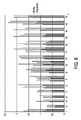
図9は、図7に示されるのと同じエクササイズの間、本発明の側面による心拍センサの出力信号101の信号及び変調を表すグラフを示す。この場合、心拍センサは、ユーザのふくらはぎに付けられる。図8及び図9を比較することにより、出力信号が、ユーザのふくらはぎに付けられる心拍センサに対してより、手首に付けられる心拍センサに対して、一層増加することが分かる。但し、腕は、ユーザの前進には直接関与しない。
FIG. 9 shows a graph representing the signal and modulation of the
血液潅流がウォームアップ段階の間、増加するとき、心拍センサの出力信号101の増加されたDC要素と増加された変調とが説明されることができる点に留意されたい。
Note that as the blood perfusion increases during the warm-up phase, the increased DC component and increased modulation of the
相対的に一定の運動を伴うランの間、運動アーチファクトが比較的一定である限り、PPG信号の振幅は、休息の間、増加することができる。 As long as the motion artifact is relatively constant during a run with a relatively constant motion, the amplitude of the PPG signal can increase during rest.
ユーザがサイドシャッフル、カリオカ、ハイニー、バットキック等といった異なる種類のエクササイズでウォームアップをしている場合、ウォームアップエクササイズが比較的短く、エクササイズの間に休息期間があるため、潅流の増加を測定するのが困難であり、それらを使用することがより良好かもしれない点に留意されたい。他方、エクササイズが、戻りパターンを持つ場合、心拍モニタシステムは、いくつかの活動分類(例えば加速度計データに基づき)を実行することができる。これは、エクササイズの間さえ、ウォームアップ状態の有効な検出を可能にする。 If the user is warming up with different types of exercises such as side shuffle, carioca, high knee, bat kick, etc., measure the increase in perfusion because the warm-up exercise is relatively short and there is a rest period between exercises Note that it may be difficult to use and it may be better to use them. On the other hand, if the exercise has a return pattern, the heart rate monitor system can perform several activity classifications (eg, based on accelerometer data). This allows for effective detection of warm-up conditions even during exercise.
図10は、指先に置かれる本発明による心拍センサの出力信号を表すグラフを示す。図10の上部において、赤色光を用いる光学心拍センサの出力信号101dが示され、下部において、赤外線を用いる光学心拍センサの出力信号101eが示される。更に、図10において、血管運動トーンにおける変化が示される。これは冷水においてセンサなしに手を水に入れることによりt=376sに誘導される。血管収縮が、全身を通り存在し、こうして、血管収縮がもたらされる点に留意されたい。図10から分かるように、変調だけでなく出力信号のパルス形態が、変化する。
FIG. 10 shows a graph representing the output signal of the heart rate sensor according to the invention placed on the fingertip. The upper part of FIG. 10 shows an
従って、本発明による心拍モニタシステムは、ユーザのウォームミングアップの状態を得るため、心拍センサの出力信号を分析する。ユーザのウォームミングアップの状態が、血液潅流に直接関連付けられるので、血液潅流を検出することは、ウォームミングアップの状態を決定することを可能にする。本発明による心拍モニタシステムは、血液潅流を決定するため、心拍センサの出力信号101の低い信号対ノイズ比(低い変調)の関係を使用する。言い換えると、心拍センサ100の出力信号の信号対ノイズ比が良好である場合、血液潅流も良好であり、ユーザがウォームアップされる。他方、信号対ノイズ比が低い場合、血液潅流も低く、ユーザが正しくウォームアップされていない。ユーザが、冷えた環境においてエクササイズを始めている場合、人体は、毛細管を閉じることにより体熱を保存しようとし、こうして、血管収縮が開始される。
Therefore, the heart rate monitor system according to the present invention analyzes the output signal of the heart rate sensor in order to obtain the warm-up state of the user. Since the user's warm-up state is directly related to blood perfusion, detecting blood perfusion allows the warm-up state to be determined. The heart rate monitor system according to the present invention uses the low signal to noise ratio (low modulation) relationship of the
本発明の側面によれば、ユーザのウォームミングアップの状態は、ユーザの実際に測定された生理的信号により検出されることができる。こうして、ユーザのウォームミングアップの状態の非常に有効で正確な決定が実行されることができる。 According to an aspect of the present invention, the warm-up state of the user can be detected by a physiological signal actually measured by the user. In this way, a very effective and accurate determination of the user's warm-up status can be performed.
本発明の側面によれば、信号分析器210は、AC要素、DC要素、又は信号の変調といったこれらの組み合わせを分析する。信号分析器210に基づき、ウォームアップ検出器220は、ユーザのウォームミングアップの状態を検出することができる。例えば、ウォームアップ検出器は、ユーザのウォームアップ状態を決定するため、出力信号のAC要素、DC要素又は変調における増加、並びに出力信号101のパルス形態を使用することができる。ユーザのウォームアップ状態は、出力ユニット300により出力されることができる。これは、グラフィカルユーザインタフェース310により、又は、無線インタフェース320により実行されることができる。ユーザ及び/又はトレーナは、光学又は音響信号により、効果的なウォーミングアップを知らされることができる。代替的に、振動信号が、出力ユニット300により出力されることもできる。
According to aspects of the present invention, the
本発明の側面によれば、ウォームアップ検出器220は、心拍センサ100の実際に分析された出力信号とメモリ221に格納される閾値とを比較することができる。例えば、DC要素における5%の増加は、閾値として使用されることができる。本発明の別の側面では、ウォームアップ検出器220は、時間にわたり振幅における変化を算出することができて(例えば、最後の10秒における平均振幅を取り、その10秒より前の平均振幅を減算する)、その値が、例えば5%の閾値と交差するとき、ウォームアップが充分であると決定することができる。追加的に又は代替的に、閾値は、ユーザ依存又はエクササイズの環境依存とすることもできる。環境の閾値は、外部の温度、体におけるセンサの位置及び活動データを考慮することもできる。ユーザ特有の閾値は、ユーザ年齢、性、民族性及び/又は皮膚のトーン及び/又はユーザの過去のエクササイズの間、測定された信号特性を考慮することもできる。
According to the aspect of the present invention, the warm-up
光学心拍センサ100の光源110は、LED又はレーザーとすることができる。代替的に、光学センサは、カメラベースとすることができ、追加的な光源なしに、環境光を用いて作動することができる。
The
本発明の好ましい実施形態において、心拍モニタシステムは、手首デバイスとして実現されることができる。従って、手首デバイスは、少なくとも1つの光学心拍センサ及び分析ユニットを有することができる。オプションで、手首デバイスは、出力ユニット300を有することもできる。
In a preferred embodiment of the present invention, the heart rate monitor system can be implemented as a wrist device. Thus, the wrist device can have at least one optical heart rate sensor and an analysis unit. Optionally, the wrist device can also have an
心拍モニタシステムは、スマートウォッチ、手首デバイス、スマート眼鏡、スマートブレスレット又は他のウェアラブル(スマート)デバイスとして実現されることができる。 The heart rate monitor system can be implemented as a smart watch, wrist device, smart glasses, smart bracelet or other wearable (smart) device.
図面、開示及び添付された請求項の研究から、開示された実施形態に対する他の変形が、請求項に記載の本発明を実施する当業者により理解され、実行されることができる。 From studying the drawings, disclosure and appended claims, other variations to the disclosed embodiments can be understood and implemented by those skilled in the art practicing the claimed invention.
請求項において、単語「有する」は他の要素又はステップを除外するものではなく、不定冠詞「a」又は「an」は複数性を除外するものではない。 In the claims, the word “comprising” does not exclude other elements or steps, and the indefinite article “a” or “an” does not exclude a plurality.
単一のユニット又はデバイスが、請求項において列挙される複数のアイテムの機能を満たすことができる。特定の手段が相互に異なる従属項に記載されるという単なる事実は、これらの手段の組み合わせが有利に使用されることができないことを意味するものではない。コンピュータプログラムは、他のハードウェアと共に又はその一部として供給される光学的記憶媒体又は固体媒体といった適切な媒体に格納/配布されることができるが、インターネット又は他の有線若しくは無線通信システムを介してといった他の形式で配布されることもできる。 A single unit or device may fulfill the functions of several items recited in the claims. The mere fact that certain measures are recited in mutually different dependent claims does not indicate that a combination of these measured cannot be used to advantage. The computer program may be stored / distributed on suitable media, such as optical storage media or solid media supplied with or as part of other hardware, but via the Internet or other wired or wireless communication systems. It can also be distributed in other formats.
請求項における任意の参照符号は、発明の範囲を限定するものとして解釈されるべきではない。 Any reference signs in the claims should not be construed as limiting the scope.
Claims (7)
ユーザの心拍を測定又は決定し、出力信号を出力するよう構成される光学的心拍センサと、
前記心拍センサからの出力信号を分析し、前記光学的心拍センサからの前記分析された出力信号に基づきユーザのウォームミングアップの状態を決定するよう構成される分析ユニットとを有し、
前記分析ユニットが、
前記出力信号のAC要素、前記出力信号のDC要素及び前記出力信号のパルス形態の少なくとも1つを分析するよう構成される信号分析器と、
前記出力信号の前記AC要素及び/若しくは前記DC要素又は前記パルス形態の信号特性に従って検出される血液潅流に基づき、前記ユーザのウォームミングアップの状態を検出するよう構成されるウォームアップ検出器ユニットとを含む、心拍モニタシステム。 A heart rate monitor system,
An optical heart rate sensor configured to measure or determine a user's heart rate and output an output signal;
An analysis unit configured to analyze an output signal from the heart rate sensor and determine a user warm-up condition based on the analyzed output signal from the optical heart rate sensor;
The analysis unit is
A signal analyzer configured to analyze at least one of an AC component of the output signal, a DC component of the output signal, and a pulse form of the output signal;
A warm-up detector unit configured to detect a warm-up condition of the user based on blood perfusion detected in accordance with the AC and / or DC elements of the output signal or the signal characteristics of the pulse form; Including a heart rate monitor system.
光学的心拍センサによりユーザの心拍を測定又は決定し、出力信号を出力するステップと、
前記心拍センサから出力信号を分析し、前記光学的心拍センサからの前記分析された出力信号に基づき、ユーザのウォームミングアップの状態を決定するステップとを有し、
前記決定するステップが、
前記出力信号のAC要素、前記出力信号のDC要素及び前記出力信号のパルス形態の少なくとも1つを信号分析器により分析するステップと、
前記出力信号の前記AC要素及び/若しくは前記DC要素又は前記パルス形態の信号特性に従って検出される血液潅流に基づき、前記ユーザのウォームミングアップの状態をウォームアップ検出器ユニットにより検出するステップとを有する、方法。 In a method for determining a user warm-up state,
Measuring or determining a user's heart rate with an optical heart rate sensor and outputting an output signal;
Analyzing an output signal from the heart rate sensor and determining a user warm-up condition based on the analyzed output signal from the optical heart rate sensor;
Said determining step comprises:
Analyzing at least one of an AC component of the output signal, a DC component of the output signal, and a pulse form of the output signal with a signal analyzer;
Detecting a warm-up state of the user by a warm-up detector unit based on blood perfusion detected according to the AC and / or DC elements of the output signal or the signal characteristics of the pulse form. ,Method.
Applications Claiming Priority (3)
| Application Number | Priority Date | Filing Date | Title |
|---|---|---|---|
| EP14178696.2 | 2014-07-28 | ||
| EP14178696 | 2014-07-28 | ||
| PCT/EP2015/066370 WO2016016016A1 (en) | 2014-07-28 | 2015-07-17 | Heart rate monitor system and method of determining a warming-up status of a user |
Publications (2)
| Publication Number | Publication Date |
|---|---|
| JP2016537142A JP2016537142A (en) | 2016-12-01 |
| JP6151861B2 true JP6151861B2 (en) | 2017-06-21 |
Family
ID=51225363
Family Applications (1)
| Application Number | Title | Priority Date | Filing Date |
|---|---|---|---|
| JP2016533726A Active JP6151861B2 (en) | 2014-07-28 | 2015-07-17 | Heart rate monitor system and method for determining user warm-up status |
Country Status (7)
| Country | Link |
|---|---|
| US (1) | US20170128024A1 (en) |
| EP (1) | EP3048961B1 (en) |
| JP (1) | JP6151861B2 (en) |
| CN (1) | CN105744886B (en) |
| PL (1) | PL3048961T3 (en) |
| RU (1) | RU2701886C2 (en) |
| WO (1) | WO2016016016A1 (en) |
Families Citing this family (6)
| Publication number | Priority date | Publication date | Assignee | Title |
|---|---|---|---|---|
| CN106419848A (en) * | 2016-10-21 | 2017-02-22 | 北京通和堂生物科技有限公司 | Device and method for monitoring thyroid function |
| CN112741601A (en) * | 2019-10-31 | 2021-05-04 | 华为技术有限公司 | Method and device for evaluating warming-up effect |
| CN112842307B (en) * | 2019-11-27 | 2022-11-01 | 华为终端有限公司 | Warming-up degree detection method and device |
| CN113996046B (en) * | 2020-07-28 | 2022-10-04 | 华为技术有限公司 | Warming-up judgment method and device and electronic equipment |
| CN114190908A (en) * | 2021-12-06 | 2022-03-18 | 深圳市爱都科技有限公司 | Warming-up sufficiency detection method and device and intelligent wearable equipment |
| CN116077041A (en) * | 2023-01-31 | 2023-05-09 | 深圳市爱都科技有限公司 | Method, device, equipment and medium for detecting fitness sufficiency |
Family Cites Families (20)
| Publication number | Priority date | Publication date | Assignee | Title |
|---|---|---|---|---|
| US4911427A (en) * | 1984-03-16 | 1990-03-27 | Sharp Kabushiki Kaisha | Exercise and training machine with microcomputer-assisted training guide |
| US4860763A (en) * | 1987-07-29 | 1989-08-29 | Schminke Kevin L | Cardiovascular conditioning and therapeutic system |
| DE69108177T2 (en) * | 1990-11-15 | 1995-09-14 | Combi Co | Climbing exercise device and method for controlling it. |
| ATE197650T1 (en) * | 1992-07-21 | 2000-12-15 | Hayle Brainpower Pty Ltd | INTERACTIVE EXERCISE MONITORING SYSTEM AND METHOD |
| RU2106108C1 (en) * | 1992-11-27 | 1998-03-10 | Александр Сергеевич Радченко | Method for determining functional state of cardiovascular system under physical load based on interaction of human organism systems for transporting and utilizing oxygen |
| US5618245A (en) * | 1994-02-04 | 1997-04-08 | True Fitness Technology, Inc. | Fitness apparatus with heart rate control system and method of operation |
| JP3567561B2 (en) * | 1995-11-09 | 2004-09-22 | セイコーエプソン株式会社 | Heart rate measuring device |
| JP4249173B2 (en) * | 1998-03-09 | 2009-04-02 | 株式会社Cskホールディングス | Training apparatus, image output processing method, and image output program |
| US20040171956A1 (en) * | 2003-01-30 | 2004-09-02 | Bruce Babashan | Heart rate monitor using color to convey information |
| WO2007097702A1 (en) * | 2006-02-21 | 2007-08-30 | Lindberg Lars-Goeran | Non-invasive monitoring of blood flow in deep tissue |
| EP2035098B1 (en) * | 2006-07-04 | 2019-08-28 | Firstbeat Technologies OY | Method and system for guiding a person in physical exercise |
| WO2008006150A1 (en) * | 2006-07-11 | 2008-01-17 | Citech Research Ip Pty Ltd | Bio-activity data capture and transmission |
| KR101040653B1 (en) * | 2009-01-21 | 2011-06-10 | 서울대학교산학협력단 | Non-contact measuring devices of pulse wave and measuring devices of oxygen saturation and blood pressure in using same |
| RU2455928C2 (en) * | 2010-07-05 | 2012-07-20 | Учреждение Российской академии наук Институт океанологии им. П.П. Ширшова РАН | Cardiomonitor |
| WO2012108895A1 (en) * | 2011-02-09 | 2012-08-16 | Massachusetts Institute Of Technology | Ear wearable vital sign monitor |
| US8961185B2 (en) * | 2011-08-19 | 2015-02-24 | Pulson, Inc. | System and method for reliably coordinating musculoskeletal and cardiovascular hemodynamics |
| CN202631976U (en) * | 2012-04-27 | 2012-12-26 | 上海典世科技发展有限公司 | Multifunctional watch system |
| US8954135B2 (en) * | 2012-06-22 | 2015-02-10 | Fitbit, Inc. | Portable biometric monitoring devices and methods of operating same |
| EP2892421A1 (en) * | 2012-09-04 | 2015-07-15 | Whoop, Inc. | Systems, devices and methods for continuous heart rate monitoring and interpretation |
| CN103735401B (en) * | 2013-10-11 | 2017-02-22 | 中国医学科学院北京协和医院 | Cardio-pulmonary resuscitation quality feedback control system based on pulse blood oxygen |
-
2015
- 2015-07-17 PL PL15739571T patent/PL3048961T3/en unknown
- 2015-07-17 US US15/036,960 patent/US20170128024A1/en not_active Abandoned
- 2015-07-17 RU RU2016116515A patent/RU2701886C2/en not_active IP Right Cessation
- 2015-07-17 CN CN201580002714.9A patent/CN105744886B/en active Active
- 2015-07-17 EP EP15739571.6A patent/EP3048961B1/en active Active
- 2015-07-17 WO PCT/EP2015/066370 patent/WO2016016016A1/en active Application Filing
- 2015-07-17 JP JP2016533726A patent/JP6151861B2/en active Active
Also Published As
| Publication number | Publication date |
|---|---|
| PL3048961T3 (en) | 2017-07-31 |
| EP3048961B1 (en) | 2017-01-25 |
| CN105744886A (en) | 2016-07-06 |
| US20170128024A1 (en) | 2017-05-11 |
| RU2016116515A (en) | 2017-11-01 |
| RU2701886C2 (en) | 2019-10-02 |
| WO2016016016A1 (en) | 2016-02-04 |
| CN105744886B (en) | 2021-03-02 |
| EP3048961A1 (en) | 2016-08-03 |
| RU2016116515A3 (en) | 2019-02-21 |
| JP2016537142A (en) | 2016-12-01 |
Similar Documents
| Publication | Publication Date | Title |
|---|---|---|
| JP6151861B2 (en) | Heart rate monitor system and method for determining user warm-up status | |
| Tang et al. | A chair–based unobtrusive cuffless blood pressure monitoring system based on pulse arrival time | |
| JP6659831B2 (en) | Biological information analyzer, system, and program | |
| JP6149037B2 (en) | Portable device, method for determining heart rate, system and computer program | |
| CN109496137B (en) | Optical vital sign sensor | |
| RU2673379C2 (en) | Monitoring system and method for monitoring hemodynamic status of subject | |
| CN104684459B (en) | Motion artifacts are recognized in the measurement of photo-plethysmographic art and improve the method and system of measurement result and the reliability of alarm | |
| CN107405090B (en) | Method and device for measuring blood pressure | |
| CN106560155A (en) | Apparatus And Method For Measuring Bioinformation | |
| US20150087928A1 (en) | Measuring tissue volume with dynamic autoreconfiguration | |
| CN107466222B (en) | Vital sign monitoring system | |
| Mukherjee et al. | A literature review on current and proposed technologies of noninvasive blood pressure measurement | |
| US20140221848A1 (en) | Biological information detecting device, biological information detecting method, and biological information detection program | |
| JP2016533846A (en) | System and method for estimating human cardiovascular fitness | |
| JP6608527B2 (en) | Device, terminal and biometric information system | |
| US10470717B2 (en) | Pulse validation | |
| JP2023532319A (en) | Apparatus and method for compensating assessment of peripheral arterial tone | |
| US20230040540A1 (en) | Optimizing Sensor Pressure in Blood Pressure Measurements Using a Wearable Device | |
| Patil et al. | CamBP: A camera-based, non-contact blood pressure monitor | |
| CN112426141A (en) | Blood pressure detection method and device and electronic equipment | |
| CN115135236A (en) | Improved personal health data collection | |
| US20240065563A1 (en) | Blood pressure measurements using cyclic pressure on a wearable device ppg sensor | |
| Das et al. | Pulse rate monitoring embedded system during indoor exercises using microcontroller | |
| WO2024084478A1 (en) | Self-recalibrating opto-mechanical blood pressure monitoring | |
| JP2024018876A (en) | Information processing system, server, information processing method, program, and learning model |
Legal Events
| Date | Code | Title | Description |
|---|---|---|---|
| A521 | Request for written amendment filed |
Free format text: JAPANESE INTERMEDIATE CODE: A523 Effective date: 20160524 |
|
| A621 | Written request for application examination |
Free format text: JAPANESE INTERMEDIATE CODE: A621 Effective date: 20160524 |
|
| A871 | Explanation of circumstances concerning accelerated examination |
Free format text: JAPANESE INTERMEDIATE CODE: A871 Effective date: 20160524 |
|
| A975 | Report on accelerated examination |
Free format text: JAPANESE INTERMEDIATE CODE: A971005 Effective date: 20161226 |
|
| A131 | Notification of reasons for refusal |
Free format text: JAPANESE INTERMEDIATE CODE: A131 Effective date: 20170105 |
|
| A521 | Request for written amendment filed |
Free format text: JAPANESE INTERMEDIATE CODE: A523 Effective date: 20170209 |
|
| RD04 | Notification of resignation of power of attorney |
Free format text: JAPANESE INTERMEDIATE CODE: A7424 Effective date: 20170214 |
|
| TRDD | Decision of grant or rejection written | ||
| A01 | Written decision to grant a patent or to grant a registration (utility model) |
Free format text: JAPANESE INTERMEDIATE CODE: A01 Effective date: 20170502 |
|
| A61 | First payment of annual fees (during grant procedure) |
Free format text: JAPANESE INTERMEDIATE CODE: A61 Effective date: 20170525 |
|
| R150 | Certificate of patent or registration of utility model |
Ref document number: 6151861 Country of ref document: JP Free format text: JAPANESE INTERMEDIATE CODE: R150 |
|
| R250 | Receipt of annual fees |
Free format text: JAPANESE INTERMEDIATE CODE: R250 |
|
| R250 | Receipt of annual fees |
Free format text: JAPANESE INTERMEDIATE CODE: R250 |
|
| R250 | Receipt of annual fees |
Free format text: JAPANESE INTERMEDIATE CODE: R250 |
|
| R250 | Receipt of annual fees |
Free format text: JAPANESE INTERMEDIATE CODE: R250 |
|
| R250 | Receipt of annual fees |
Free format text: JAPANESE INTERMEDIATE CODE: R250 |