RU2673379C2 - Monitoring system and method for monitoring hemodynamic status of subject - Google Patents
Monitoring system and method for monitoring hemodynamic status of subject Download PDFInfo
- Publication number
- RU2673379C2 RU2673379C2 RU2016107845A RU2016107845A RU2673379C2 RU 2673379 C2 RU2673379 C2 RU 2673379C2 RU 2016107845 A RU2016107845 A RU 2016107845A RU 2016107845 A RU2016107845 A RU 2016107845A RU 2673379 C2 RU2673379 C2 RU 2673379C2
- Authority
- RU
- Russia
- Prior art keywords
- subject
- pat
- measurements
- signal
- monitoring
- Prior art date
Links
- 238000012544 monitoring process Methods 0.000 title claims abstract description 65
- 230000000004 hemodynamic effect Effects 0.000 title claims abstract description 55
- 238000000034 method Methods 0.000 title claims abstract description 43
- 238000005259 measurement Methods 0.000 claims abstract description 83
- 238000011156 evaluation Methods 0.000 claims abstract description 25
- 238000013186 photoplethysmography Methods 0.000 claims abstract description 9
- 230000036772 blood pressure Effects 0.000 claims description 40
- 230000036387 respiratory rate Effects 0.000 claims description 11
- 238000009530 blood pressure measurement Methods 0.000 claims description 9
- 230000029058 respiratory gaseous exchange Effects 0.000 claims description 8
- 238000012800 visualization Methods 0.000 claims description 7
- 238000012360 testing method Methods 0.000 claims description 5
- 101100053823 Arabidopsis thaliana PAT20 gene Proteins 0.000 claims 1
- 238000003384 imaging method Methods 0.000 abstract description 6
- 230000000694 effects Effects 0.000 abstract description 2
- 239000003814 drug Substances 0.000 abstract 1
- 239000000126 substance Substances 0.000 abstract 1
- 230000000241 respiratory effect Effects 0.000 description 10
- 239000008280 blood Substances 0.000 description 9
- 210000004369 blood Anatomy 0.000 description 9
- 238000001514 detection method Methods 0.000 description 8
- 230000006870 function Effects 0.000 description 8
- 206010036590 Premature baby Diseases 0.000 description 5
- 238000004458 analytical method Methods 0.000 description 5
- 230000008859 change Effects 0.000 description 5
- 238000004590 computer program Methods 0.000 description 5
- 230000000875 corresponding effect Effects 0.000 description 5
- 210000001061 forehead Anatomy 0.000 description 5
- 230000033001 locomotion Effects 0.000 description 5
- 206010005746 Blood pressure fluctuation Diseases 0.000 description 4
- 238000003672 processing method Methods 0.000 description 4
- 206010042772 syncope Diseases 0.000 description 4
- 230000035488 systolic blood pressure Effects 0.000 description 4
- 230000005540 biological transmission Effects 0.000 description 3
- 230000001419 dependent effect Effects 0.000 description 3
- 230000002159 abnormal effect Effects 0.000 description 2
- 210000001367 artery Anatomy 0.000 description 2
- QVGXLLKOCUKJST-UHFFFAOYSA-N atomic oxygen Chemical compound [O] QVGXLLKOCUKJST-UHFFFAOYSA-N 0.000 description 2
- 108091008698 baroreceptors Proteins 0.000 description 2
- 238000010586 diagram Methods 0.000 description 2
- 210000003128 head Anatomy 0.000 description 2
- 208000011316 hemodynamic instability Diseases 0.000 description 2
- 238000012806 monitoring device Methods 0.000 description 2
- 230000003287 optical effect Effects 0.000 description 2
- 230000002746 orthostatic effect Effects 0.000 description 2
- 229910052760 oxygen Inorganic materials 0.000 description 2
- 239000001301 oxygen Substances 0.000 description 2
- 210000001774 pressoreceptor Anatomy 0.000 description 2
- 230000008569 process Effects 0.000 description 2
- 230000011514 reflex Effects 0.000 description 2
- 230000003595 spectral effect Effects 0.000 description 2
- 239000004753 textile Substances 0.000 description 2
- 238000002834 transmittance Methods 0.000 description 2
- 210000000707 wrist Anatomy 0.000 description 2
- HRANPRDGABOKNQ-ORGXEYTDSA-N (1r,3r,3as,3br,7ar,8as,8bs,8cs,10as)-1-acetyl-5-chloro-3-hydroxy-8b,10a-dimethyl-7-oxo-1,2,3,3a,3b,7,7a,8,8a,8b,8c,9,10,10a-tetradecahydrocyclopenta[a]cyclopropa[g]phenanthren-1-yl acetate Chemical compound C1=C(Cl)C2=CC(=O)[C@@H]3C[C@@H]3[C@]2(C)[C@@H]2[C@@H]1[C@@H]1[C@H](O)C[C@@](C(C)=O)(OC(=O)C)[C@@]1(C)CC2 HRANPRDGABOKNQ-ORGXEYTDSA-N 0.000 description 1
- 208000019901 Anxiety disease Diseases 0.000 description 1
- 208000005156 Dehydration Diseases 0.000 description 1
- 208000010496 Heart Arrest Diseases 0.000 description 1
- 208000036647 Medication errors Diseases 0.000 description 1
- 206010042434 Sudden death Diseases 0.000 description 1
- 210000001015 abdomen Anatomy 0.000 description 1
- 230000036506 anxiety Effects 0.000 description 1
- 208000008784 apnea Diseases 0.000 description 1
- 238000013459 approach Methods 0.000 description 1
- 230000004872 arterial blood pressure Effects 0.000 description 1
- 230000035581 baroreflex Effects 0.000 description 1
- 230000008901 benefit Effects 0.000 description 1
- 238000013155 cardiography Methods 0.000 description 1
- 239000003795 chemical substances by application Substances 0.000 description 1
- 230000006835 compression Effects 0.000 description 1
- 238000007906 compression Methods 0.000 description 1
- 230000008602 contraction Effects 0.000 description 1
- 230000002596 correlated effect Effects 0.000 description 1
- 230000008878 coupling Effects 0.000 description 1
- 238000010168 coupling process Methods 0.000 description 1
- 238000005859 coupling reaction Methods 0.000 description 1
- 230000018044 dehydration Effects 0.000 description 1
- 238000006297 dehydration reaction Methods 0.000 description 1
- 230000006866 deterioration Effects 0.000 description 1
- 238000003745 diagnosis Methods 0.000 description 1
- 230000035487 diastolic blood pressure Effects 0.000 description 1
- 230000008482 dysregulation Effects 0.000 description 1
- 210000000624 ear auricle Anatomy 0.000 description 1
- 230000002526 effect on cardiovascular system Effects 0.000 description 1
- 238000000605 extraction Methods 0.000 description 1
- 210000003414 extremity Anatomy 0.000 description 1
- 239000004744 fabric Substances 0.000 description 1
- 210000003811 finger Anatomy 0.000 description 1
- 239000011888 foil Substances 0.000 description 1
- 230000036541 health Effects 0.000 description 1
- 230000003862 health status Effects 0.000 description 1
- 208000019622 heart disease Diseases 0.000 description 1
- 238000005286 illumination Methods 0.000 description 1
- 210000004072 lung Anatomy 0.000 description 1
- 239000003550 marker Substances 0.000 description 1
- 238000000691 measurement method Methods 0.000 description 1
- 230000000414 obstructive effect Effects 0.000 description 1
- 210000000056 organ Anatomy 0.000 description 1
- 230000010355 oscillation Effects 0.000 description 1
- 230000000803 paradoxical effect Effects 0.000 description 1
- 230000036581 peripheral resistance Effects 0.000 description 1
- 230000002028 premature Effects 0.000 description 1
- 238000012545 processing Methods 0.000 description 1
- 230000035485 pulse pressure Effects 0.000 description 1
- 230000029865 regulation of blood pressure Effects 0.000 description 1
- 230000008844 regulatory mechanism Effects 0.000 description 1
- 230000004044 response Effects 0.000 description 1
- 230000000284 resting effect Effects 0.000 description 1
- 230000035945 sensitivity Effects 0.000 description 1
- 230000011664 signaling Effects 0.000 description 1
- 201000002859 sleep apnea Diseases 0.000 description 1
- 238000010561 standard procedure Methods 0.000 description 1
- 230000024883 vasodilation Effects 0.000 description 1
- 238000012795 verification Methods 0.000 description 1
Images
Classifications
-
- A—HUMAN NECESSITIES
- A61—MEDICAL OR VETERINARY SCIENCE; HYGIENE
- A61B—DIAGNOSIS; SURGERY; IDENTIFICATION
- A61B5/00—Measuring for diagnostic purposes; Identification of persons
- A61B5/02—Detecting, measuring or recording pulse, heart rate, blood pressure or blood flow; Combined pulse/heart-rate/blood pressure determination; Evaluating a cardiovascular condition not otherwise provided for, e.g. using combinations of techniques provided for in this group with electrocardiography or electroauscultation; Heart catheters for measuring blood pressure
- A61B5/021—Measuring pressure in heart or blood vessels
- A61B5/02108—Measuring pressure in heart or blood vessels from analysis of pulse wave characteristics
- A61B5/02125—Measuring pressure in heart or blood vessels from analysis of pulse wave characteristics of pulse wave propagation time
-
- A—HUMAN NECESSITIES
- A61—MEDICAL OR VETERINARY SCIENCE; HYGIENE
- A61B—DIAGNOSIS; SURGERY; IDENTIFICATION
- A61B5/00—Measuring for diagnostic purposes; Identification of persons
- A61B5/0002—Remote monitoring of patients using telemetry, e.g. transmission of vital signals via a communication network
-
- A—HUMAN NECESSITIES
- A61—MEDICAL OR VETERINARY SCIENCE; HYGIENE
- A61B—DIAGNOSIS; SURGERY; IDENTIFICATION
- A61B5/00—Measuring for diagnostic purposes; Identification of persons
- A61B5/02—Detecting, measuring or recording pulse, heart rate, blood pressure or blood flow; Combined pulse/heart-rate/blood pressure determination; Evaluating a cardiovascular condition not otherwise provided for, e.g. using combinations of techniques provided for in this group with electrocardiography or electroauscultation; Heart catheters for measuring blood pressure
- A61B5/024—Detecting, measuring or recording pulse rate or heart rate
- A61B5/02416—Detecting, measuring or recording pulse rate or heart rate using photoplethysmograph signals, e.g. generated by infrared radiation
-
- A—HUMAN NECESSITIES
- A61—MEDICAL OR VETERINARY SCIENCE; HYGIENE
- A61B—DIAGNOSIS; SURGERY; IDENTIFICATION
- A61B5/00—Measuring for diagnostic purposes; Identification of persons
- A61B5/24—Detecting, measuring or recording bioelectric or biomagnetic signals of the body or parts thereof
- A61B5/316—Modalities, i.e. specific diagnostic methods
- A61B5/318—Heart-related electrical modalities, e.g. electrocardiography [ECG]
Abstract
Description
ОБЛАСТЬ ТЕХНИКИ, К КОТОРОЙ ОТНОСИТСЯ ИЗОБРЕТЕНИЕFIELD OF THE INVENTION
Настоящее изобретение относится к системе мониторинга и к соответствующему способу для мониторинга гемодинамического статуса субъекта, в частности для мониторинга изменения кровяного давления субъекта, такого как пациент или недоношенный ребенок. Настоящее изобретение дополнительно относится к процессору и соответствующему способу обработки, а также к компьютерной программе для осуществления упомянутого способа обработки для использования в такой системе мониторинга.The present invention relates to a monitoring system and to an appropriate method for monitoring the hemodynamic status of a subject, in particular for monitoring changes in blood pressure of a subject, such as a patient or premature baby. The present invention further relates to a processor and a corresponding processing method, as well as to a computer program for implementing said processing method for use in such a monitoring system.
УРОВЕНЬ ТЕХНИКИBACKGROUND
В области медицинских систем мониторинга доступны устройства мониторинга, имеющие акселерометр, расположенный в положении у верхушки легкого для того, чтобы измерять пульс и дыхание пациента, манжетный аппарат для измерения кровяного давления на плече и, дополнительно, фотоплетизмографический (PPG) датчик на запястье или на кончике пальца. Эти датчики позволяют осуществлять непрерывный мониторинг пациента.In the field of medical monitoring systems, monitoring devices are available that have an accelerometer located at the apex of the lung to measure the patient’s pulse and breathing, a cuff device for measuring blood pressure on the shoulder and, in addition, a photoplethysmographic (PPG) sensor on the wrist or tip finger. These sensors allow continuous monitoring of the patient.
Было найдено, что раннее распознавание трудно различимых признаков ухудшения состояния пациента является главной проблемой для систем мониторинга пациента.It was found that early recognition of difficult to distinguish signs of deterioration of the patient's condition is a major problem for patient monitoring systems.
Непрерывное измерение кровяного давления может быть необходимым для некоторых пациентов, имеющих например гемодинамическую нестабильность, которая может привести к увеличенному риску для пациента. Кроме того, это часто важно для мониторинга недоношенных детей в отделении интенсивной терапии новорожденных (NICU). Неинвазивные измерения кровяного давления основаны главным образом на сфигмоманометрической окклюзионной манжете, которая может обеспечить только прерывистые измерения. Этот способ не только является неудобным для пациента, или даже трудным в использовании, например для недоношенных детей, но также возможно, что критические изменения кровяного давления могут быть пропущены во время временных интервалов между измерениями кровяного давления. Кровяное давление обычно измеряется только однажды или дважды в день с низкой разрешающей способностью.Continuous blood pressure measurement may be necessary for some patients who have, for example, hemodynamic instability, which may lead to an increased risk to the patient. In addition, it is often important for monitoring premature infants in the neonatal intensive care unit (NICU). Non-invasive blood pressure measurements are mainly based on the sphygmomanometric occlusal cuff, which can only provide intermittent measurements. This method is not only inconvenient for the patient, or even difficult to use, for example for premature babies, but it is also possible that critical changes in blood pressure can be skipped during the time intervals between blood pressure measurements. Blood pressure is usually measured only once or twice a day with low resolution.
Следовательно, имеется большая заинтересованность в устройствах мониторинга, которые обеспечивали бы непрерывное обнаружение существенных изменений гемодинамического статуса, и в частности кровяного давления.Therefore, there is great interest in monitoring devices that would ensure the continuous detection of significant changes in hemodynamic status, and in particular blood pressure.
Способ для мониторинга изменений кровяного давления, известный в данной области техники, основан на методологии времени поступления пульсовой волны, причем частота сердечных сокращений получается из электрокардиограммы, а изменения кровяного давления определяются в комбинации с фотоплетизмограммой, которая получается соответствующим фотооптическим датчиком на кончике пальца, ухе, лбу или запястье пациента. Время поступления пульсовой волны определяется как сумма периода напряжения и времени прохождения пульсовой волны, причем период напряжения, период изоволюметрического сжатия, может изменяться независимо от кровяного давления, так что надежность этого способа уменьшается. Однако было показано, что использование относительных изменений времени поступления пульсовой волны может служить практически подходящим параметром для раннего обнаружения приближающихся обмороков из-за понижения кровяного давления, причем уменьшение давления на 20 мм рт.ст. связывается с изменением времени поступления пульсовой волны на 20 -40 мс.A method for monitoring changes in blood pressure, known in the art, is based on a pulse wave arrival time methodology, wherein the heart rate is obtained from an electrocardiogram, and changes in blood pressure are determined in combination with a photoplethysmogram, which is obtained by a corresponding photo-optical sensor on a fingertip, ear, the patient’s forehead or wrist. The pulse wave arrival time is defined as the sum of the voltage period and the pulse wave propagation time, moreover, the voltage period, the period of isovolumetric compression, can vary regardless of blood pressure, so the reliability of this method is reduced. However, it was shown that the use of relative changes in the pulse wave arrival time can be an almost suitable parameter for the early detection of impending syncope due to a decrease in blood pressure, with a pressure decrease of 20 mmHg. associated with a change in the time of arrival of the pulse wave by 20 -40 ms.
Патентный документ WO 2013/093690 A1 раскрывает устройство для использования в мониторинге барорецепторного рефлекса у пользователя. Это устройство содержит процессор, выполненный с возможностью обрабатывать сигнал, выводимый первым датчиком, который присоединен к кровати или расположен рядом с ней, для определения момента, когда пользователь перемещается из лежачего положения на кровати в сидячее положение, и для обеспечения индикации барорецепторного рефлекса пользователя путем обработки сигнала для определения изменения частоты сердечных сокращений пользователя, которое происходит в результате перемещения из лежачего положения в сидячее положение.Patent document WO 2013/093690 A1 discloses a device for use in monitoring a baroreceptor reflex in a user. This device includes a processor configured to process a signal output by a first sensor that is attached to or adjacent to the bed to determine when the user is moving from the bed to a sitting position and to provide an indication of the user's baroreceptor reflex by processing a signal for determining a change in a user's heart rate that occurs as a result of moving from a lying position to a sitting position.
Публикация Wong M. Y. M. et al.: «Contactless recording of photoplethysmogram on a sleeping bed», PROCEEDINGS OF THE 31ST ANNUAL INTERNATIONAL CONFERENCE OF THE IEEE ENGINEERING IN MEDICINE AND BIOLOGY SOCIETY: ENGINEERING THE FUTURE OF BIОMEDICINE, EMBC 2009, IEEE, 3 September 2009 (2009-09-03), pages 907-910, раскрывает бесконтактный способ мониторинга для записи фотоплетизмограммы (PPG) в отражающем режиме на кровати для оценки частоты сердечных сокращений (HR). Электрокардиограмма (ECG) и время прохождения пульсовой волны (PTT) также измерялись в этом исследовании. ECG измерялась на конечностях субъектов, в то время как PPG получалась на их правом указательном пальце и на спине с прямым контактом между датчиком PPG и кожей субъектов и без такого контакта, соответственно. Четкие волновые формы PPG были получены со спин субъектов даже при том, что датчик не был присоединен непосредственно к их коже. HR в реальном времени, выведенная из фотоплетизмограмм, полученных со спины, близко коррелировалась с измеренными на пальце PPG и ECG.Wong MYM et al .: “Contactless recording of photoplethysmogram on a sleeping bed”, PROCEEDINGS OF THE 31ST ANNUAL INTERNATIONAL CONFERENCE OF THE IEEE ENGINEERING IN MEDICINE AND BIOLOGY SOCIETY: ENGINEERING THE FUTURE OF BIOMEDICINE, EMBC 2009, IEEE, September 3, 2009 ( 2009-09-03), pages 907-910, discloses a non-contact monitoring method for recording photoplethysmogram (PPG) in reflective mode on a bed for estimating heart rate (HR). An electrocardiogram (ECG) and pulse wave transit time (PTT) were also measured in this study. ECG was measured on the limbs of the subjects, while PPG was obtained on their right index finger and on the back with direct contact between the PPG sensor and the skin of the subjects and without such contact, respectively. Clear waveforms of PPG were obtained from the backs of the subjects even though the sensor was not attached directly to their skin. Real-time HR derived from photoplethysmograms obtained from the back was closely correlated with PPG and ECG measured on the finger.
Публикация VIKRAM CHANDRASEKARAN ET AL: «Cuffless Differential Blood Pressure Estimation Using Smart Phones», IEEE TRANSACTIONS ON BIOMEDICAL ENGINEERING, IEEE SERVICE CENTER, PISCATAWAY, NJ, USA, vol. 60, no. 4, 1 April 2013, pages 1080-1089, раскрывает два способа оценки дифференциального кровяного давления, использующих данные о сердечных сокращениях и пульсовой волне. Первый способ использует два смартфона, тогда как второй способ заменяет один из телефонов специализированным внешним микрофоном. Систолическое и диастолическое давление в этих двух способах оцениваются путем вычисления пульсового давления и систолического объема крови из записанных данных.Publication of VIKRAM CHANDRASEKARAN ET AL: “Cuffless Differential Blood Pressure Estimation Using Smart Phones”, IEEE TRANSACTIONS ON BIOMEDICAL ENGINEERING, IEEE SERVICE CENTER, PISCATAWAY, NJ, USA, vol. 60, no. 4, April 1, 2013, pages 1080-1089, discloses two methods for estimating differential blood pressure using heart rate and pulse wave data. The first method uses two smartphones, while the second method replaces one of the phones with a specialized external microphone. Systolic and diastolic blood pressure in these two methods are evaluated by calculating the pulse pressure and systolic blood volume from the recorded data.
Система мониторинга для мониторинга гемодинамического статуса, в частности для обнаружения гемодинамического кризиса субъекта, например, недоношенного ребенка в отделении для новорожденных без нательных датчиков (например, электродов, которые вредят коже новорожденных) в настоящий момент является недоступной.A monitoring system for monitoring hemodynamic status, in particular for detecting the hemodynamic crisis of a subject, for example, a premature baby in the neonatal ward without body sensors (for example, electrodes that harm the skin of newborns), is currently unavailable.
СУЩНОСТЬ ИЗОБРЕТЕНИЯSUMMARY OF THE INVENTION
Задачей настоящего изобретения является предоставить улучшенную систему мониторинга и способ для мониторинга гемодинамического статуса субъекта, которые обеспечивали бы непрерывный мониторинг с низкими техническими усилиями, увеличенным комфортом и повышенным уровнем безопасности для субъекта, и которые были бы особенно полезными для мониторинга недоношенных детей.The present invention is to provide an improved monitoring system and method for monitoring the hemodynamic status of the subject, which would provide continuous monitoring with low technical effort, increased comfort and increased level of safety for the subject, and which would be especially useful for monitoring premature babies.
В соответствии с одним аспектом настоящего изобретения предлагается процессор для использования в системе мониторинга для мониторинга гемодинамического статуса субъекта, содержащий:In accordance with one aspect of the present invention, there is provided a processor for use in a monitoring system for monitoring the hemodynamic status of a subject, comprising:
- блок фотоплетизмографии для формирования сигналов фотоплетизмографии (PPG) из различных мест на теле субъекта по множеству изображений субъекта, получаемых с отдаленного расстояния с течением времени, иa photoplethysmography unit for generating photoplethysmography (PPG) signals from various places on the subject’s body from a plurality of subject images obtained from a remote distance over time, and
- блок оценки для общей оценки полученного сигнала датчика субъекта, относящегося к показателю жизненно важной функции субъекта, и для оценки упомянутого фотоплетизмографического сигнала для извлечения измерений времени поступления пульсовой волны (PAT), а также извлечения гемодинамической информации о гемодинамическом статусе субъекта из упомянутых измерений PAT.- an assessment unit for a general assessment of the received sensor signal of a subject related to an indicator of the vital function of the subject, and for evaluating said photoplethysmographic signal for extracting pulse wave arrival time (PAT) measurements, as well as extracting hemodynamic information about a subject’s hemodynamic status from said PAT measurements.
В соответствии с другим аспектом настоящего изобретения предлагается система мониторинга для мониторинга гемодинамического статуса субъекта, содержащая:In accordance with another aspect of the present invention, there is provided a monitoring system for monitoring the hemodynamic status of a subject, comprising:
- блока визуализации для получения множества изображений субъекта с отдаленного расстояния с течением времени,- a visualization unit for obtaining a plurality of images of a subject from a distant distance over time,
- блока датчика для получения сигнала датчика, относящегося к показателю жизненно важной функции субъекта, и- a sensor unit for receiving a sensor signal related to an indicator of the vital function of the subject, and
- процессора, раскрытый в настоящем документе.- a processor disclosed herein.
В дополнительных аспектах настоящего изобретения предоставляются соответствующие способы, компьютерная программа, которая содержит средства программного кода для того, чтобы заставить компьютер выполнять этапы способа обработки, раскрытого в настоящем документе, когда упомянутая компьютерная программа выполняется на компьютере, а также энергонезависимый машиночитаемый носитель записи, на котором хранится компьютерный программный продукт, который при его выполнении процессором вызывает выполнение способа обработки, раскрытого в настоящем документе.In further aspects of the present invention, corresponding methods are provided, a computer program that comprises program code means for causing a computer to perform the steps of the processing method disclosed herein when said computer program is executed on a computer, as well as a non-volatile computer-readable recording medium on which a computer software product is stored which, when executed by the processor, causes the processing method disclosed in Astoyan document.
Предпочтительные варианты осуществления настоящего изобретения определяются в зависимых пунктах формулы изобретения. Следует понимать, что заявленные способы, процессор, компьютерная программа и носитель записи имеют сходные и/или идентичные предпочтительные варианты осуществления с заявленной системой, и как это определено в зависимых пунктах формулы изобретения.Preferred embodiments of the present invention are defined in the dependent claims. It should be understood that the claimed methods, processor, computer program, and recording medium have similar and / or identical preferred embodiments to the claimed system, and as defined in the dependent claims.
Настоящее изобретение основано на идее использовать бесконтактный способ для получения PPG сигнала, который используется в качестве одного элемента при извлечении гемодинамической информации (например, кровяного давления) о гемодинамическом статусе субъекта. Упомянутый бесконтактный способ является общеизвестным и использует принцип удаленной PPG для получения показателей жизненно важных функций, таких как частота сердечных сокращений, частота дыхания или SpO2 субъекта. Этот способ использует блок визуализации, такой как камера (например, видеокамера), для получения временных последовательностей кадров изображения субъекта, которые затем используются для формирования PPG сигнала известным образом.The present invention is based on the idea of using a non-contact method to obtain a PPG signal, which is used as one element in the extraction of hemodynamic information (eg, blood pressure) about the hemodynamic status of a subject. Mentioned non-contact method is well known and uses the principle of remote PPG to obtain indicators of vital functions, such as heart rate, respiratory rate or SpO2 of the subject. This method uses a visualization unit, such as a camera (for example, a video camera), to obtain time sequences of image frames of a subject, which are then used to generate a PPG signal in a known manner.
Настоящее изобретение использует в качестве второго элемента сигнал датчика, который относится к показателю жизненно важной функции субъекта, и который получается блоком датчика (включающего в себя один или более идентичных или различных датчиков). Этот блок датчика также предпочтительно выполнен с возможностью измерения сигнала датчика без расположения датчиков на теле субъекта.The present invention uses a sensor signal as a second element, which refers to an indicator of the vital function of a subject, and which is obtained by a sensor unit (including one or more identical or different sensors). This sensor unit is also preferably configured to measure the sensor signal without arranging the sensors on the subject's body.
Посредством комбинированного анализа PPG сигнала и сигнала датчика может быть получена достоверная и непосредственная информация о гемодинамическом статусе, и в частности об изменениях гемодинамического статуса субъекта, без использования детектирующих средств, присоединяемых к телу субъекта, предпочтительно бесконтактным образом. Кроме того, непрерывный контроль является легко реализуемым. Предложенная система, таким образом, обеспечивает увеличенный комфорт и может использоваться для непрерывного мониторинга недоношенных детей, например в NICU.By combined analysis of the PPG signal and the sensor signal, reliable and direct information about the hemodynamic status, and in particular about changes in the hemodynamic status of the subject, without the use of detecting agents attached to the body of the subject, preferably in a non-contact manner, can be obtained. In addition, continuous monitoring is easy to implement. The proposed system, thus, provides increased comfort and can be used for continuous monitoring of premature babies, for example in the NICU.
В соответствии с одним вариантом осуществления упомянутый блок оценки выполнен с возможностью определения изменения кровяного давления из общей оценки упомянутого сигнала датчика и упомянутого PPG сигнала. PPG сигнал предоставляет информацию о пульсовых колебаниях объема крови, а сигнал датчика предоставляет информацию о показателе жизненно важной функции, такой как частота сердечных сокращений, или даже представляет сигнал электрокардиограммы. Из комбинации этих двух сигналов может быть определен некоторый сигнал длительности, который соответствует скорости, с которой вызванная сердечным сокращением волна давления проходит по артериальной системе субъекта. Изменение в кровяном давлении может быть затем определено на основе этого сигнала длительности. Так как кровяное давление определяется просто измерением PPG сигнала и сигнала датчика, техническое усилие для определения изменений в кровяном давлении уменьшается, субъект не должен надевать (например, манжетное) устройство измерения кровяного давления, и тенденции изменения кровяного давления могут измеряться непрерывно и почти в реальном времени, так что гарантируется высокая надежность этого измерения.In accordance with one embodiment, said evaluation unit is configured to determine changes in blood pressure from an overall assessment of said sensor signal and said PPG signal. The PPG signal provides information about pulse fluctuations in blood volume, and the sensor signal provides information about an indicator of vital function, such as heart rate, or even represents an electrocardiogram signal. From the combination of these two signals, a certain signal of duration can be determined, which corresponds to the speed at which the pressure wave caused by the heartbeat passes through the subject's arterial system. The change in blood pressure can then be determined based on this duration signal. Since blood pressure is simply determined by measuring the PPG signal and the sensor signal, the technical effort to detect changes in blood pressure is reduced, the subject does not have to put on a (for example, cuffed) device for measuring blood pressure, and trends in blood pressure can be measured continuously and in near real time. so that high reliability of this measurement is guaranteed.
В соответствии с настоящим изобретением упомянутый блок оценки выполнен с возможностью извлечения измерений времени поступления пульсовой волны (PAT), а также извлечения гемодинамической информации о гемодинамическом статусе субъекта из упомянутых измерений PAT. Неограничивающими примерами таких измерений PAT являются значения PATfoot, PAT20%, PAT50%, PAT80%, PATtop, время прохождения пульсовой волны и/или периода напряжения. Такие измерения PAT являются общеизвестными в известной методологии PAT. Из комбинации фотоплетизмографического сигнала и сигнала датчика такие измерения PAT могут легко получаться и отслеживаться для того, чтобы обнаружить изменения гемодинамического статуса субъекта. Измерение фотоплетизмографического сигнала в различных местах на теле, например на лбу и на стопе, позволяет обнаруживать измерения времени прохождения пульсовой волны (PTT), на которые не влияет период напряжения. Более точно, в математических терминах, взятие разности по меньшей мере двух измеренных PAT устраняет вклад PEP, и остается только разность PTT.In accordance with the present invention, said evaluation unit is configured to extract pulse wave arrival time (PAT) measurements, as well as extract hemodynamic information about a subject’s hemodynamic status from said PAT measurements. Nonlimiting examples of such measurement values are PAT PAT foot, PAT 20%, PAT 50%, PAT 80%, PAT top, pulse wave transit time and / or voltage period. Such PAT measurements are well known in the well-known PAT methodology. From a combination of the photoplethysmographic signal and the sensor signal, such PAT measurements can be easily obtained and monitored in order to detect changes in the hemodynamic status of the subject. Measurement of the photoplethysmographic signal at various places on the body, such as the forehead and foot, makes it possible to detect pulse wave transit time (PTT) measurements that are not affected by the voltage period. More precisely, in mathematical terms, taking the difference of at least two measured PAT eliminates the contribution of PEP, and only the difference of the PTT remains.
Предпочтительно упомянутый блок оценки выполнен с возможностью определения начального сигнала измерения PAT из сигнала датчика, и конечного сигнала измерения PAT из значения систолического измерения PPG сигнала. Время начала и время окончания таким образом могут быть определены с низкими техническими усилиями и с высокой точностью.Preferably, said evaluation unit is configured to determine an initial PAT measurement signal from a sensor signal, and an end PAT measurement signal from a systolic PPG measurement value of the signal. The start time and end time can thus be determined with low technical effort and with high accuracy.
В соответствии с другим вариантом осуществления упомянутый блок оценки выполнен с возможностью обнаружения изменений в одном или более измерениях PAT и выдачи сигнала индикации, указывающего на то, что были обнаружены изменения в одном или более измерениях PAT. Например, сигнал критического положения или тревоги может быть подан сиделке, медсестре или врачу, например через пейджер, телефон или другие сигнальные средства, в случае, если было обнаружено серьезное изменение гемодинамического статуса.In accordance with another embodiment, said evaluation unit is configured to detect changes in one or more PAT measurements and to provide an indication signal indicating that changes in one or more PAT measurements have been detected. For example, an emergency or alarm signal may be given to a caregiver, nurse, or doctor, for example, via a pager, telephone, or other signaling device, if a serious change in hemodynamic status is detected.
Упомянутый блок оценки также предпочтительно выполнен с возможностью сравнения одного или более извлеченных измерений PAT с опорными измерениями PAT, полученными ранее для того же самого субъекта или для различных субъектов, или сформированными из измерений PAT, полученных для множества субъектов (например, сформированными как среднее значение измерений PAT для различных субъектов). Это дополнительно увеличивает надежность и точность мониторинга гемодинамического статуса.Said evaluation unit is also preferably configured to compare one or more extracted PAT measurements with reference PAT measurements obtained previously for the same subject or for different subjects, or formed from PAT measurements obtained for a plurality of subjects (for example, generated as the average value of the measurements PAT for various subjects). This further increases the reliability and accuracy of monitoring hemodynamic status.
Блок датчика предпочтительно содержит датчик ECG, в частности емкостной датчик ECG, для получения сигнала датчика ECG, позволяющего извлекать сигнал частоты сердечных сокращений, относящийся к частоте сердечных сокращений субъекта. Кроме того, в одном варианте осуществления блок датчика дополнительно или альтернативно содержит датчик давления для получения сигнала датчика давления, представляющего изменения давления, позволяющего извлекать сигнал частоты сердечных сокращений, относящийся к частоте сердечных сокращений субъекта, и/или сигнал дыхания, относящийся к частоте дыхания субъекта. Такой датчик ECG и такой датчик давления являются общеизвестными и могут быть, например, встроенными в матрац или ткань, на которой лежит пациент, например в кровать пациента.The sensor unit preferably comprises an ECG sensor, in particular a capacitive ECG sensor, for receiving an ECG sensor signal capable of extracting a heart rate signal related to the heart rate of the subject. In addition, in one embodiment, the sensor unit further or alternatively comprises a pressure sensor for receiving a pressure sensor signal representing pressure changes allowing to extract a heart rate signal related to a subject's heart rate and / or a breathing signal related to a subject's respiratory rate . Such an ECG sensor and such a pressure sensor are well known and may, for example, be embedded in the mattress or fabric on which the patient is lying, for example in the patient’s bed.
Дыхание влияет на измерения PAT, так как внутригрудное давление модулируется дыхательным усилием. Анализ корреляции дыхательного усилия и измерений PAT позволяет определять, например, явления апноэ во время сна. Ширина PPG сигнала пульсовой волны предоставляет информацию о системном сосудистом сопротивлении и используется для получения заключений о процессах централизации или вазодилатации, например во время критических явлений, таких как остановка сердца.Breathing influences PAT measurements, as intrathoracic pressure is modulated by respiratory effort. An analysis of the correlation of respiratory effort and PAT measurements allows for the determination, for example, of sleep apnea. The width of the PPG pulse wave signal provides information on systemic vascular resistance and is used to draw conclusions about centralization or vasodilation processes, for example during critical events such as cardiac arrest.
В случае, если блок датчика содержит и датчик ECG, и датчик давления, блок оценки выполняется с возможностью извлечения измерений времени поступления пульсовой волны (PAT) из различных комбинаций фотоплетизмографического сигнала, сигнала датчика ECG и сигнала датчика давления для того, чтобы проверить упомянутые измерения PAT на непротиворечивость и использовать результат упомянутой проверки при извлечении гемодинамической информации о гемодинамическом статусе субъекта. Таким образом точность и надежность результата мониторинга могут быть дополнительно увеличены. Противоречивые результаты могут, например, игнорироваться так, чтобы только непротиворечивые результаты использовались для определения гемодинамических изменений. Если все измерения PAT, полученные из различных комбинаций сигналов, являются противоречивыми, это может быть интерпретировано в одном варианте осуществления как указание на низкое качество сигнала или неточное измерение одного или более сигналов, и в этом случае соответствующий выходной сигнал может быть выведен так, чтобы пользователь мог проверить настройки измерения.In the event that the sensor unit contains both the ECG sensor and the pressure sensor, the evaluation unit is configured to extract pulse wave arrival time (PAT) measurements from various combinations of the photoplethysmographic signal, the ECG sensor signal, and the pressure sensor signal in order to verify said PAT measurements for consistency and use the result of the said test when extracting hemodynamic information about the hemodynamic status of the subject. Thus, the accuracy and reliability of the monitoring result can be further increased. Conflicting results can, for example, be ignored so that only consistent results are used to determine hemodynamic changes. If all PAT measurements obtained from different signal combinations are inconsistent, this may be interpreted in one embodiment as indicating a poor signal quality or inaccurate measurement of one or more signals, in which case the corresponding output signal may be output so that the user could check the measurement settings.
В другом варианте осуществления система мониторинга может дополнительно содержать блок измерения кровяного давления, например манжетное измерительное устройство кровяного давления, для измерения кровяного давления субъекта. Этот блок измерения кровяного давления может использоваться для прерывистого измерения с тем, чтобы проверить определенную гемодинамическую информацию, например изменение кровяного давления, посредством точного измерения время от времени и калибровки измерений PAT.In another embodiment, the monitoring system may further comprise a blood pressure measuring unit, such as a cuffed blood pressure measuring device, for measuring a subject's blood pressure. This blood pressure measurement unit can be used for intermittent measurement in order to check certain hemodynamic information, such as a change in blood pressure, by accurately measuring from time to time and calibrating PAT measurements.
В дополнительном предпочтительном варианте осуществления блок оценки выполнен с возможностью управления блоком измерения кровяного давления на основе определенной гемодинамической информации. Следовательно, измерение кровяного давления может быть выполнено только в том случае, если обнаруживается существенное изменение гемодинамического статуса, чтобы уменьшить частоту измерений кровяного давления.In a further preferred embodiment, the evaluation unit is configured to control a blood pressure measurement unit based on certain hemodynamic information. Therefore, a blood pressure measurement can only be performed if a significant change in hemodynamic status is detected in order to reduce the frequency of blood pressure measurements.
КРАТКОЕ ОПИСАНИЕ ЧЕРТЕЖЕЙBRIEF DESCRIPTION OF THE DRAWINGS
Эти и другие аспекты настоящего изобретения будут объяснены и станут очевидными из ссылок на вариант(ы) осуществления, описанные здесь и далее. На следующих чертежахThese and other aspects of the present invention will be explained and become apparent from the references to the embodiment (s) described hereinafter. In the following drawings
Фиг. 1 показывает принципиальную схему одного варианта осуществления системы мониторинга в соответствии с настоящим изобретением,FIG. 1 shows a schematic diagram of one embodiment of a monitoring system in accordance with the present invention,
Фиг. 2 показывает график электрокардиограммы и фотоплетизмограммы для иллюстрации методологии PAT,FIG. 2 shows a graph of an electrocardiogram and photoplethysmogram to illustrate the PAT methodology,
Фиг. 3 показывает график, иллюстрирующий типичное увеличение PAT в случае уменьшения кровяного давления,FIG. 3 shows a graph illustrating a typical increase in PAT in the event of a decrease in blood pressure,
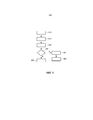
Фиг. 4 показывает блок-схему, иллюстрирующую первый вариант осуществления способа мониторинга в соответствии с настоящим изобретением,FIG. 4 shows a flowchart illustrating a first embodiment of a monitoring method in accordance with the present invention,
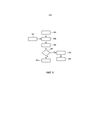
Фиг. 5 показывает блок-схему, иллюстрирующую второй вариант осуществления способа мониторинга в соответствии с настоящим изобретением, иFIG. 5 shows a flowchart illustrating a second embodiment of a monitoring method in accordance with the present invention, and
Фиг. 6 показывает блок-схему, иллюстрирующую третий вариант осуществления способа мониторинга в соответствии с настоящим изобретением.FIG. 6 shows a flowchart illustrating a third embodiment of a monitoring method in accordance with the present invention.
ОСУЩЕСТВЛЕНИЕ ИЗОБРЕТЕНИЯDETAILED DESCRIPTION OF THE INVENTION
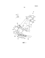
Фиг. 1 показывает принципиальную схему системы 10 мониторинга в соответствии с настоящим изобретением для мониторинга гемодинамического статуса субъекта 100, например пациента, лежащего в кровати 102, причем голова субъекта 100 располагается на подушке 104, и субъект 100 покрыт одеялом 106. Система 10 содержит блок 12 визуализации для получения множества изображений 13 субъекта 100 во времени, блок 14 датчика для получения сигнала 15 датчика субъекта 100, относящегося к показателю жизненно важной функции субъекта 100, блок 16 PPG для формирования сигнала 17 фотоплетизмографии (PPG) из упомянутого множества изображений, и блок 18 оценки для общей оценки упомянутого сигнала 15 датчика и упомянутого сигнала 17 PPG для извлечения гемодинамической информации 19 о гемодинамическом статусе субъекта 100.FIG. 1 shows a schematic diagram of a
В этой схеме блок 12 визуализации устанавливается на отдаленном расстоянии, например на потолке или на стене комнаты, в которой располагается кровать 102. Обычно естественного света достаточно для освещения сцены, но дополнительный источник 20 света может присутствовать для того, чтобы осветить сцену и гарантировать достаточную контрастность изображения. В одном варианте осуществления блок 12 визуализации может быть монохромной или одноцветной камерой, например инфракрасной камерой или видеокамерой, а источник 20 света может быть соответствующим источником света, например источником инфракрасного света. Следует понимать, что в дополнительных вариантах осуществления блок 12 визуализации может быть выполнен с возможностью обнаруживать свет в видимой и/или инфракрасной спектральной области, а источник 20 света может быть выполнен с возможностью излучать свет в инфракрасной и/или видимой спектральной области. В этом варианте осуществления субъект 100 и блок 12 визуализации располагаются напротив друг друга, однако следует понимать, что блок 12 визуализации и источник 20 света в принципе могут быть произвольно ориентированы относительно субъекта 100.In this scheme, the
В блоке 16 PPG, который может быть осуществлен как программное обеспечение, выполняющееся на процессоре или компьютере, и/или как специализированная аппаратура, сигнал 17 генерируется из множества изображений 13, получаемых блоком визуализации. Плетизмография обычно относится к измерению изменений объема органа или части тела, и в частности к обнаружению изменений объема из за сердечнососудистой пульсовой волны, проходящей через тело субъекта при каждом сердцебиении. Фотоплетизмография (PPG) является оптической техникой измерений, которая оценивает изменение во времени коэффициента отражения или пропускания света интересующей области или объема. PPG основана на том принципе, что кровь поглощает свет больше чем окружающая ткань, так что вариации объема крови с каждым сердцебиением влияют соответственно на коэффициент пропускания или отражения. Помимо информации о частоте сердечных сокращений, волновая форма PPG может содержать в себе информацию, которую можно приписать дополнительным физиологическим явлениям, таким как дыхание. Путем оценки пропускания и/или отражения на различных длинах волн (обычно красных и инфракрасных) может быть определено насыщение крови кислородом.In
Обычные пульсоксиметры для измерения частоты сердечных сокращений и насыщения кислородом (артериальной) крови субъекта присоединяются к коже субъекта, например к кончику пальца, мочке уха или лбу. Поэтому они упоминаются как «контактные» PPG устройства. Типичный пульсоксиметр содержит красный светоизлучающий диод (LED) и инфракрасный LED в качестве источников света и один фотодиод для обнаружения света, прошедшего через ткань пациента. Коммерчески доступные пульсоксиметры быстро переключаются между измерениями на красной и инфракрасной длине волны и таким образом измеряют пропускание одной и той же области или объема ткани на двух различных длинах волн. Это упоминается как мультиплексирование с разделением времени. Пропускание во времени на каждой длине волны дает волновые формы PPG для красной и инфракрасной длин волн. Хотя контактная PPG рассматривается как в основном неинвазивный метод, контактное PPG измерение часто воспринимается как неприятное, так как пульсоксиметр присоединяется непосредственно к субъекту, и его кабели ограничивают свободу перемещения.Conventional pulse oximeters for measuring the heart rate and oxygen saturation of the subject’s (arterial) blood are attached to the subject’s skin, such as the tip of a finger, earlobe, or forehead. Therefore, they are referred to as “contact” PPG devices. A typical pulse oximeter contains a red light emitting diode (LED) and infrared LED as light sources and one photodiode for detecting light transmitted through a patient’s tissue. Commercially available pulse oximeters quickly switch between measurements at the red and infrared wavelengths and thus measure the transmission of the same region or volume of tissue at two different wavelengths. This is referred to as time division multiplexing. The time transmission at each wavelength gives PPG waveforms for red and infrared wavelengths. Although contact PPG is seen as a largely non-invasive method, contact PPG measurement is often perceived as unpleasant, as the pulse oximeter attaches directly to the subject and its cables limit freedom of movement.
В соответствии с настоящим изобретением применяется метод бесконтактной дистанционной PPG для незаметных измерений, в соответствии с которым временной ряд изображений одной или более частей кожи субъекта оценивается, как описано, например, в публикации Verkruysse et al., «Remote plethysmographic imaging using ambient light», Optics Express, 16(26), 22 December 2008, pp. 21434-21445, где продемонстрировано, что PPG сигналы могут быть измерены дистанционно с использованием естественного света и обычной видеокамеры потребительского уровня. Таким образом обнаруживаются тонкие изменения цвета кожи, вызываемые пульсовыми колебаниями объема крови. Интересующая область 22 обычно является лицом, в частности лбом или щекой, но может быть другими открытыми частями кожных областей (например, шеей или горлом) на субъекте, например телом новорожденного, который одет только в подгузник. Та же самая камера может также измерять частоту дыхания путем мониторинга дыхательного движения грудной клетки и/или живота субъекта с использованием другой интересующей области 24.In accordance with the present invention, a non-contact remote PPG method is used for invisible measurements, according to which the time series of images of one or more parts of the subject’s skin is evaluated, as described, for example, in Verkruysse et al., “Remote plethysmographic imaging using ambient light”, Optics Express, 16 (26), 22 December 2008, pp. 21434-21445, where it is demonstrated that PPG signals can be measured remotely using natural light and a conventional consumer-grade video camera. Thus, subtle changes in skin color caused by pulse fluctuations in blood volume are detected. Region of
Блок 14 датчика для получения сигнала 15 датчика субъекта 100, относящегося к показателю жизненно важной функции (например, к частоте сердечных сокращений или к частоте дыхания) субъекта 100 предпочтительно содержит один или более датчиков 141 давления и/или один или более емкостных датчиков 142, которые предпочтительно располагаются в матраце 103 кровати 102. Датчики 141 давления (например, на основе пьезоэлектрической фольги) производят сигналы 151 датчика давления, которые обнаруживают распределение веса и динамические изменения давления для того, чтобы определить осанку и извлечь дыхательные движения и сердцебиение, например, на основе баллистокардиографии, которая измеряет баллистические силы на сердце. Емкостные датчики 142 производят (ECG-подобные) сигналы 152 датчика ECG, которые могут использоваться для извлечения информации о частоте сердечных сокращений. Следует понимать, что один или все датчики блока 14 датчика также могут быть интегрированы в текстильную структуру, такую как одеяло 106 или подушка 104, или могут быть интегрированы в текстиль, носимый субъектом 100. Такие датчики раскрыты, например, в публикациях Van der Loss et. al., Unobtrusive Vital Signs Monitoring from a Multisensor Bed Sheet, RESNA'2001 Reno, NV, June 22-26, 2001 и Eilebrecht et. al., Multichannel ECG-measurement-system with capacitive patient coupling, Biomed Tech 2010, 55 (Suppl. 1), и описания таких датчиков, содержащиеся внутри этих документов, являются включенными в настоящий документ посредством ссылки.The
Блок 18 оценки, который может быть осуществлен как программное обеспечение, выполняющееся на процессоре или компьютере, и/или как специализированная аппаратура, например как программное обеспечение, выполняющееся на том же самом процессоре, что и блок 14 PPG, обычно оценивает сигнал 15 датчика (включая сигнал 151 датчика давления и сигнал 152 датчика ECG в данном варианте осуществления), а также упомянутый PPG сигнал 17 для извлечения гемодинамической информации 19 о гемодинамическом статусе субъекта 100.An
Гемодинамическая нестабильность и сбои в регуляции кровяного давления могут иметь тяжелые последствия для человека. Это, например, связано с более высоким риском падения для взрослых или даже с критическими состояниями здоровья, такими как внезапная смерть. Падения могут вызвать переломы, госпитализацию, более длительное пребывание в больнице и утрату независимости. Базовые первопричины таких явлений весьма различны и могут быть обусловлены структурными заболеваниями сердца, обезвоживанием, тревожностью, психологическим или физическим стрессом или ошибками при приеме лекарств, которые довольно распространены, в особенности для госпитализированных пациентов.Hemodynamic instability and interruptions in the regulation of blood pressure can have serious consequences for humans. This, for example, is associated with a higher risk of falling for adults or even critical health conditions such as sudden death. Falls can cause fractures, hospitalization, longer hospital stays and loss of independence. The underlying root causes of such phenomena are very different and may be due to structural heart diseases, dehydration, anxiety, psychological or physical stress, or medication errors, which are quite common, especially for hospitalized patients.
Кровяное давление, измеряемое непрерывно, может быть параметром для обнаружения сбоев регуляции. Однако неинвазивные непрерывные измерения кровяного давления методом разгруженной артерии посредством обычных носимых устройств являются сложными, тяжелыми, склонными к артефактам и требующими обученного персонала для своей работы.Continuous blood pressure may be a parameter for detecting dysregulation. However, non-invasive continuous blood pressure measurements using the unloaded artery method using conventional wearable devices are complex, heavy, prone to artifacts, and require trained personnel for their work.
В соответствии с одним предпочтительным вариантом осуществления настоящего изобретения изменения кровяного давления или, более широко, гемодинамического статуса (в частности изменения гемодинамики) отслеживаются на основе методологии времени поступления пульсовой волны (PAT). Измерения PAT в соответствии с одним вариантом осуществления настоящего изобретения выводятся из PPG сигнала 17 и сигнала 15 датчика, в частности ECG-подобного сигнала, выводимого из сигнала 151 датчика давления и/или сигнала 152 датчика ECG.In accordance with one preferred embodiment of the present invention, changes in blood pressure or, more generally, hemodynamic status (in particular hemodynamic changes) are monitored based on a pulse wave arrival time (PAT) methodology. PAT measurements in accordance with one embodiment of the present invention are derived from the
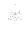
Фиг. 2 показывает электрокардиограмму (представленную сигналом 15 датчика или полученную из сигнала 15 датчика в соответствии с настоящим изобретением), и фотоплетизмограмму (PPG сигнал 17) для оценки времени поступления пульсовой волны. Электрокардиограмма и фотоплетизмограмма снимаются в различных положениях на человеческом теле 12 для того, чтобы измерять время прохождения пульсовой волны и обнаруживать тенденции в кровяном давлении из времени поступления пульсовой волны.FIG. 2 shows an electrocardiogram (represented by a
Время поступления пульсовой волны обычно определяется как период времени от максимального пика R электрокардиограммы до определенного момента времени фотоплетизмограммы. Время поступления пульсовой волны может быть обнаружено как период времени от максимальной величины R электрокардиограммы до минимального значения F фотоплетизмограммы в качестве нижнего времени поступления пульсовой волны PATfoot, или до максимального значения T фотоплетизмограммы в качестве верхнего времени поступления пульсовой волны PATtop, или как время до максимального наклона фотоплетизмограммы между максимальным и минимальным значением фотоплетизмограммы. Обычно время поступления пульсовой волны (PAT) является суммой периода напряжения (PEP), определяемого путем измерения аортального закрытия и времени прохождения пульсовой волны (PTT), как, например, описано в публикациях X. Aubert, J. Muehlsteff, «Non-Invasive Cuff-less Measurements of the Arterial Blood Pressure: What does Pulse-Transit-Time tell us all about?», Proc. ESGCO’06, Jena, Germany, May 2006 и J. Muehlsteff, X. Aubert, M. Schuett, «Cuff-less Estimation of Systolic Blood Pressure for Short Effort Bicycle Tests: The Prominent Role of the Pre-Ejection Period», EMBC'06, pp. xy, New York, 2006.The pulse wave arrival time is usually defined as the time period from the maximum peak R of the electrocardiogram to a specific point in time of the photoplethysmogram. The arrival time of the pulse wave can be detected as a time period from a maximum value R of the electrocardiogram to the minimum value F photoplethysmogram as the lower the arrival time of the pulse wave PAT foot, or to the maximum value T photoplethysmogram as an upper time of receipt of the pulse wave PAT top, or both time before the maximum slope of the photoplethysmogram between the maximum and minimum values of the photoplethysmogram. Typically, the pulse wave arrival time (PAT) is the sum of the voltage period (PEP) determined by measuring the aortic closure and the pulse wave propagation time (PTT), as, for example, described by X. Aubert, J. Muehlsteff, Non-Invasive Cuff -less Measurements of the Arterial Blood Pressure: What does Pulse-Transit-Time tell us all about? ”, Proc. ESGCO'06, Jena, Germany, May 2006 and J. Muehlsteff, X. Aubert, M. Schuett, “Cuff-less Estimation of Systolic Blood Pressure for Short Effort Bicycle Tests: The Prominent Role of the Pre-Ejection Period”, EMBC '06, pp. xy, New York, 2006.
PTT может использоваться в качестве маркера изменений кровяного давления благодаря его четко определенному отношению к кровяному давлению и основано на распространении пульсовой волны в эластичных артериях. Однако PEP - период изоволюметрического сокращения - может изменяться независимо от кровяного давления. Следовательно, некоторые недостатки этого способа были показаны для отслеживания абсолютного кровяного давления, но он обеспечивает достаточную эффективность для отслеживания вариаций кровяного давления.PTT can be used as a marker of changes in blood pressure due to its clearly defined relationship to blood pressure and is based on the propagation of a pulse wave in the elastic arteries. However, PEP - the period of isovolumetric contraction - can vary regardless of blood pressure. Therefore, some of the disadvantages of this method have been shown to track absolute blood pressure, but it provides sufficient efficacy to track variations in blood pressure.
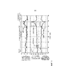
Фиг. 3 показывает графики изменения частоты сердечных сокращений, параметра PATfoot и систолического кровяного давления (SBP) с течением времени. Эти графики показывают типичное увеличение PAT (средний график) вследствие критического уменьшения кровяного давления (нижний график). Это измерение было получено во время теста на ортостатическом столе, используемого в качестве стандартной процедуры при диагностике первопричин обморока. Дополнительные исследования с использованием диагностического пассивного упражнения стоя (теста на ортостатическом столе с поднятой головой [HUTT]) показали, что уменьшение давления на 20 мм рт.ст. связано с изменением PAT на 20-40 мс, что может быть легко обнаружено, и таким образом доказали возможность использования относительных изменений PAT для раннего обнаружения угрожающих обмороков.FIG. 3 shows graphs of changes in heart rate, PAT foot, and systolic blood pressure (SBP) over time. These graphs show a typical increase in PAT (middle graph) due to a critical decrease in blood pressure (lower graph). This measurement was obtained during an orthostatic table test, used as a standard procedure for diagnosing the underlying causes of syncope. Additional studies using a diagnostic passive standing exercise (test on an orthostatic table with a raised head [HUTT]) showed that the pressure was reduced by 20 mmHg. associated with a PAT change of 20-40 ms, which can be easily detected, and thus proved the possibility of using relative PAT changes for the early detection of threatening syncope.
Система и способ мониторинга в соответствии с настоящим изобретением достигают улучшенной надежности отдельных измерений с использованием бесконтактных способов и обеспечивают доступ к гемодинамическому статусу и изменениям гемодинамического статуса с использованием только бесконтактных способов считывания. Они делают возможным раннее обнаружение критических гемодинамических явлений у новорожденных с использованием только бесконтактных способов. Кроме того, настоящее изобретение расширяет доступные параметры текущих бесконтактных способов, такие как частота сердечных сокращений, вариабельность частоты сердечных сокращений, дыхательные движения с помощью гемодинамических заместителей, которые не были доступными до сих пор, и гарантирует увеличенную безопасность пациента благодаря более подходящему параметру для обнаружения кризиса с использованием только бесконтактных датчиков. Алгоритм для объединения сигналов позволяет ему более надежно извлекать момент начала пульсовых колебаний крови. Настоящее изобретение хорошо подходит к текущей последовательности операций без дополнительных усилий, например для размещения дополнительных датчиков.The monitoring system and method in accordance with the present invention achieve improved reliability of individual measurements using non-contact methods and provide access to hemodynamic status and changes in hemodynamic status using only non-contact reading methods. They make possible the early detection of critical hemodynamic phenomena in newborns using only non-contact methods. In addition, the present invention extends the available parameters of current non-contact methods, such as heart rate, heart rate variability, respiratory movements with hemodynamic substituents that were not available until now, and guarantees increased patient safety due to a more suitable parameter for crisis detection using only proximity sensors. The algorithm for combining signals allows it to more reliably extract the moment of the onset of pulse blood oscillations. The present invention is well suited to the current flow of operations without additional effort, for example to accommodate additional sensors.
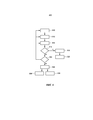
Фиг. 4 показывает блок-схему, иллюстрирующую первый вариант осуществления способа мониторинга в соответствии с настоящим изобретением, относящегося к проверке правдоподобия, улучшенному покрытию и надежности измерений частоты сердечных сокращений и частоты дыхания. На этапе S10 измерение фотоплетизмограммы на лбу, пальце или в других местах тела производится с помощью анализа вариаций силы сигнала (освещенности) с использованием, например, одноцветной или монохромной камеры. Интересующая область может обнаруживаться автоматически или определяться вручную для обнаружения поступления волны кровяного давления. На этапе S12 производятся емкостные измерения изменений ECG и/или изменений давления в матраце или ткани (прижима), из которых определяются частота сердечных сокращений, изменения частоты сердечных сокращений и/или частота дыхания. На этапе S14 сравниваются скорости и/или изменения скорости из всех источников сигнала. На этапе S16 проверяется надежность и непротиворечивость этих измерений. Если они являются непротиворечивыми, измеренные сигналы классифицируются как «хорошие» (S18), и выведенная частота сердечных сокращений и/или частота дыхания извлекаются только из «хорошего» сигнала (S20). Если они не являются непротиворечивыми, например если один сигнал противоречит двум другим сигналам, осуществляется проверка на артефакты в сигналах (S22). Если никаких артефактов не находится по меньшей мере в одном сигнале, этому сигналу присваивается метка «самое высокое доверие» (S24), выведенная частота сердечных сокращений и/или частота дыхания извлекаются только из сигнала с «самым высоким доверием» (S26) или сообщается среднее значение двух сигналов с более высоким доверием, чем у третьего сигнала (этап S28). Если найдены артефакты, способ возвращается к одной из более ранних этапов S10, S12, S14.FIG. 4 shows a flowchart illustrating a first embodiment of a monitoring method in accordance with the present invention related to likelihood verification, improved coverage and reliability of measurements of heart rate and respiratory rate. At step S10, the measurement of the photoplethysmogram on the forehead, finger, or other parts of the body is performed by analyzing variations in signal strength (illumination) using, for example, a single-color or monochrome camera. The region of interest can be detected automatically or manually determined to detect the arrival of a blood pressure wave. At step S12, capacitive measurements of ECG changes and / or pressure changes in the mattress or tissue (clamp) are made, from which the heart rate, changes in heart rate and / or respiratory rate are determined. At step S14, the speeds and / or changes in speed from all signal sources are compared. At step S16, the reliability and consistency of these measurements is checked. If they are consistent, the measured signals are classified as “good” (S18), and the derived heart rate and / or respiratory rate are extracted only from the “good” signal (S20). If they are not consistent, for example, if one signal contradicts two other signals, an artifact check in the signals is checked (S22). If no artifacts are found in at least one signal, the signal is labeled “highest confidence” (S24), the derived heart rate and / or respiratory rate are extracted only from the signal with “highest confidence” (S26) or the average is reported the value of two signals with higher confidence than the third signal (step S28). If artifacts are found, the method returns to one of the earlier steps S10, S12, S14.
Фиг. 5 показывает блок-схему, иллюстрирующую второй вариант осуществления способа мониторинга в соответствии с настоящим изобретением, относящийся к проверке правдоподобия измерений PAT из вывода гемодинамических изменений, основанных на подходе измерения PAT. Некоторые из этапов этого способа являются идентичными этапам способа, показанного на Фиг. 4, и таким образом обозначаются теми же самыми ссылочными обозначениями. После измерения фотоплетизмограммы (PPG) на этапе S10 и измерения емкостной ECG (cECG) и/или изменений давления на этапе S12 для вывода начальной точки волны давления одно или более измерений PAT нескольких или всех возможных комбинаций (cECG - PPG, давление - PPG, cECG - давление) извлекаются на этапе S30. На этапе S32 проверяется непротиворечивость извлеченных измерений PAT и/или изменений PAT. Если они являются непротиворечивыми, сообщаются извлеченные измерения PAT и/или изменения PAT (S34), и информация о гемодинамическом статусе субъекта может быть выведена (S36) на основе вышеупомянутой зависимости между измерениями PAT и гемодинамикой. Если на извлеченных измерениях PAT и/или изменениях PAT обнаруживаются существенные изменения, генерируется уведомление или оповещение о низком качестве сигнала (S38).FIG. 5 shows a flowchart illustrating a second embodiment of a monitoring method in accordance with the present invention related to verifying the likelihood of PAT measurements from deriving hemodynamic changes based on a PAT measurement approach. Some of the steps of this method are identical to the steps of the method shown in FIG. 4, and thus are denoted by the same reference signs. After measuring the photoplethysmogram (PPG) in step S10 and measuring the capacitive ECG (cECG) and / or pressure changes in step S12 to display the starting point of the pressure wave, one or more PAT measurements of several or all possible combinations (cECG - PPG, pressure - PPG, cECG - pressure) are extracted in step S30. At step S32, the consistency of the extracted PAT measurements and / or PAT changes is checked. If they are consistent, retrieved PAT measurements and / or PAT changes are reported (S34), and subject hemodynamic status information can be derived (S36) based on the aforementioned relationship between PAT measurements and hemodynamics. If significant changes are detected in the extracted PAT measurements and / or PAT changes, a notification or alert of low signal quality is generated (S38).
Фиг. 6 показывает блок-схему, иллюстрирующую третий вариант осуществления способа мониторинга в соответствии с настоящим изобретением, относящийся к раннему обнаружению гемодинамических изменений на основе сравнения измерений PAT с опорными измерениями. На фазе калибровки измерения PAT извлекаются на этапе S40, как описано выше со ссылкой на Фиг. 5 (этапы S10, S12, S30). Измерения PAT, извлеченные в течение этого периода, определяются затем как опорное PAT (PATref) на этапе S42. Опционально кровяное давление измеряется (S44) во время этого измерения, например, при помощи манжетного аппарата для измерения кровяного давления (30 на Фиг. 1, обеспечивающего измерение сигналов 31 кровяного давления, используемых для верификации результата оценки в блоке 18 оценки) для прерывистых измерений кровяного давления.FIG. 6 shows a flowchart illustrating a third embodiment of a monitoring method in accordance with the present invention related to the early detection of hemodynamic changes based on a comparison of PAT measurements with reference measurements. In the calibration phase, the PAT measurements are retrieved in step S40, as described above with reference to FIG. 5 (steps S10, S12, S30). The PAT measurements taken during this period are then determined as the reference PAT (PAT ref ) in step S42. Optionally, blood pressure is measured (S44) during this measurement, for example, using a cuff apparatus for measuring blood pressure (30 in FIG. 1, providing measurement of blood pressure signals 31 used to verify the result of the evaluation in evaluation unit 18) for intermittent blood measurements pressure.
На фазе мониторинга измерения PAT извлекаются на этапе S46, как описано выше со ссылкой на Фиг. 5 (этапы S10, S12, S30), после которой следуют этапы S32-S38, как показано на Фиг. 5. Также на фазе мониторинга может использоваться манжетное измерение кровяного давления (не показано) для того, чтобы калибровать измерение PAT для улучшения измерения в целом.In the monitoring phase, the PAT measurements are retrieved in step S46, as described above with reference to FIG. 5 (steps S10, S12, S30), followed by steps S32-S38, as shown in FIG. 5. Also, a cuff measurement of blood pressure (not shown) may be used in the monitoring phase to calibrate the PAT measurement to improve the measurement as a whole.
Доступ к гемодинамическим измерениям, таким как кровяное давление, позволяет лучше оценить состояние здоровья пациента. Комбинированный анализ изменений частоты сердечных сокращений и кровяного давления дает представление о том, являются ли механизмы регуляции в теле нормальными или нет. Это известно как барорефлекторный ответ и является важным для оценки риска обморока у пациента, как, например, описано в публикации J. Muehlsteff, Pattern Analysis of Pulse Arrival Time and Heart Rate towards Continuous Hemodynamic Monitoring in Low Acuity Settings, BMT 2010, Rostock. Соответственно, в одном варианте осуществления блок оценки выполнен с возможностью анализа сигнала частоты сердечных сокращений, относящегося к частоте сердечных сокращений субъекта, а также изменений кровяного давления, причем упомянутый сигнал частоты сердечных сокращений получается из упомянутого сигнала датчика и/или из упомянутого PPG сигнала.Access to hemodynamic measurements, such as blood pressure, allows you to better assess the patient’s health status. A combined analysis of changes in heart rate and blood pressure gives an idea of whether the regulatory mechanisms in the body are normal or not. This is known as a baroreflex response and is important for assessing the risk of fainting in a patient, as described, for example, in J. Muehlsteff, Pattern Analysis of Pulse Arrival Time and Heart Rate towards Continuous Hemodynamic Monitoring in Low Acuity Settings, BMT 2010, Rostock. Accordingly, in one embodiment, the evaluation unit is configured to analyze a heart rate signal relating to the heart rate of the subject as well as changes in blood pressure, said heart rate signal being obtained from said sensor signal and / or from said PPG signal.
Другое применение имеет дело с тем фактом, что измерения PAT являются чувствительными к изменениям интраторакального давления, которые происходят, например, во время явлений апноэ. Комбинированная интерпретация дыхательного усилия и его влияния на измерения PAT обеспечивает обнаружение обструктивных явлений, когда обычно сигналы дыхательного усилия показывают почти нормальные дыхательные движения, тогда как интраторакальное давление изменяется ненормально, и обнаруживает эти явления с более высокой чувствительностью и специфичностью по сравнению с измерениями, использующими только сигнал дыхательного усилия. Соответственно, в одном варианте осуществления блок датчика выполнен с возможностью получения сигнала дыхания, относящегося к частоте дыхания субъекта, и блок оценки выполнен с возможностью извлечения одного или более измерений PAT и анализа корреляции упомянутого сигнала дыхания и одного или более упомянутых измерений PAT. С этой целью может использоваться система мониторинга для мониторинга субъекта, содержащая блок визуализации, выполненный с возможностью получения множества изображений субъекта во времени, блок датчика, выполненный с возможностью получения сигнала дыхания, относящегося к частоте дыхания субъекта, блок PPG, выполненный с возможностью формирования фотоплетизмографического (PPG) сигнала из упомянутого множества изображений, и блок оценки, выполненный с возможностью извлечения одного или более измерений времени поступления пульсовой волны (PAT) и анализа корреляции упомянутого сигнала дыхания и одного или более упомянутых измерений PAT.Another application deals with the fact that PAT measurements are sensitive to changes in intrathoracic pressure that occur, for example, during apnea events. A combined interpretation of respiratory effort and its effect on PAT measurements provides for the detection of obstructive phenomena, when usually the signals of respiratory effort show almost normal respiratory movements, while intrathoracic pressure changes abnormally, and detects these phenomena with higher sensitivity and specificity compared to measurements using only signal of respiratory effort. Accordingly, in one embodiment, the sensor unit is configured to receive a respiration signal related to the respiratory rate of a subject, and the evaluation unit is configured to extract one or more PAT measurements and analyze the correlation of said respiration signal and one or more of said PAT measurements. For this purpose, a monitoring system for monitoring a subject can be used, comprising a visualization unit configured to obtain a plurality of images of the subject in time, a sensor unit configured to receive a respiratory signal related to the respiratory rate of the subject, a PPG unit configured to generate photoplethysmographic ( PPG) of a signal from said plurality of images, and an evaluation unit adapted to extract one or more measurements of the arrival time of the pulse wave s (PAT) and the analysis of the correlation of said respiration signal and one or more of the PAT measurement.
Другое применение имеет дело с обнаружением и диагностикой парадоксального пульса, когда наблюдается аномальное изменение кровяного давления (обычно более чем на 10 мм рт.ст.) во время вдоха. Соответственно, в одном варианте осуществления блок оценки выполнен с возможностью определения наличия аномального изменения кровяного давления во время вдоха.Another application is the detection and diagnosis of a paradoxical pulse when an abnormal change in blood pressure (usually more than 10 mmHg) is observed during inspiration. Accordingly, in one embodiment, the evaluation unit is configured to determine if there is an abnormal change in blood pressure during inspiration.
Настоящее изобретение может быть выгодно применено в интенсивной терапии новорожденных, например новорожденного, располагающегося в инкубаторе, или под лучевым источником тепла, или даже свернувшегося калачиком. Настоящее изобретение может быть дополнительно применено в неотложной помощи, для мониторинга внутри автомобиля, при уходе на дому и в приложениях для фитнеса.The present invention can be advantageously applied in the intensive care of newborns, for example, a newborn located in an incubator, or under a radiant heat source, or even curled up. The present invention can be additionally applied in emergency care, for monitoring inside the car, for home care and in fitness applications.
В то время как настоящее изобретение было подробно проиллюстрировано и описано в чертежах и предшествующем описании, такую иллюстрацию и описание следует считать иллюстративными или примерными и не ограничивающими; настоящее изобретение не ограничивается раскрытыми вариантами осуществления. Другие вариации раскрытых вариантов осуществления могут быть поняты и сделаны при осуществлении заявленного изобретения специалистами в данной области техники на основе изучения чертежей, описания и приложенной формулы изобретения.While the present invention has been illustrated and described in detail in the drawings and the preceding description, such illustration and description should be considered illustrative or exemplary and not limiting; the present invention is not limited to the disclosed embodiments. Other variations of the disclosed embodiments may be understood and made by practicing the claimed invention by those skilled in the art based on the study of the drawings, description and appended claims.
В формуле изобретения слова «содержащий» не исключают других элементов или этапов, а форма единственного числа не исключает множественного числа. Единственный элемент или другой блок могут выполнять функции нескольких пунктов формулы изобретения. Тот факт, что некоторые меры приведены во взаимно различных зависимых пунктах формулы изобретения, не означает, что комбинация этих мер не может быть использована для получения выгод.In the claims, the words “comprising” do not exclude other elements or steps, and the singular form does not exclude the plural. A single element or other block may fulfill the functions of several claims. The fact that some measures are given in mutually different dependent claims does not mean that a combination of these measures cannot be used to obtain benefits.
Компьютерная программа может храниться/распространяться на подходящем носителе, таком как оптический носитель данных или твердотельный носитель, поставляемый вместе с другими аппаратными средствами или как их часть, но также может распространяться в других формах, таких как через Интернет или другие проводные или беспроводные телекоммуникационные системы.The computer program may be stored / distributed on a suitable medium, such as an optical storage medium or solid-state medium, supplied with or as part of other hardware, but may also be distributed in other forms, such as via the Internet or other wired or wireless telecommunication systems.
Любые ссылочные обозначения в формуле изобретения не должны рассматриваться как ограничивающие объем настоящего изобретения.Any reference signs in the claims should not be construed as limiting the scope of the present invention.
Claims (33)
Applications Claiming Priority (5)
| Application Number | Priority Date | Filing Date | Title |
|---|---|---|---|
| US201361863017P | 2013-08-07 | 2013-08-07 | |
| US61/863,017 | 2013-08-07 | ||
| EP13179554.4 | 2013-08-07 | ||
| EP13179554 | 2013-08-07 | ||
| PCT/EP2014/066118 WO2015018675A1 (en) | 2013-08-07 | 2014-07-28 | Monitoring system and method for monitoring the hemodynamic status of a subject |
Publications (3)
| Publication Number | Publication Date |
|---|---|
| RU2016107845A RU2016107845A (en) | 2017-09-14 |
| RU2016107845A3 RU2016107845A3 (en) | 2018-05-10 |
| RU2673379C2 true RU2673379C2 (en) | 2018-11-26 |
Family
ID=48979562
Family Applications (1)
| Application Number | Title | Priority Date | Filing Date |
|---|---|---|---|
| RU2016107845A RU2673379C2 (en) | 2013-08-07 | 2014-07-28 | Monitoring system and method for monitoring hemodynamic status of subject |
Country Status (8)
| Country | Link |
|---|---|
| US (1) | US20170202463A1 (en) |
| EP (1) | EP3030145B1 (en) |
| JP (1) | JP6410820B2 (en) |
| CN (1) | CN105491942A (en) |
| BR (1) | BR112016002488A2 (en) |
| MX (1) | MX358093B (en) |
| RU (1) | RU2673379C2 (en) |
| WO (1) | WO2015018675A1 (en) |
Families Citing this family (27)
| Publication number | Priority date | Publication date | Assignee | Title |
|---|---|---|---|---|
| US10028668B2 (en) * | 2014-05-06 | 2018-07-24 | Alivecor, Inc. | Blood pressure monitor |
| US9575560B2 (en) | 2014-06-03 | 2017-02-21 | Google Inc. | Radar-based gesture-recognition through a wearable device |
| US11169988B2 (en) | 2014-08-22 | 2021-11-09 | Google Llc | Radar recognition-aided search |
| US9778749B2 (en) | 2014-08-22 | 2017-10-03 | Google Inc. | Occluded gesture recognition |
| CA2962581A1 (en) * | 2014-09-05 | 2016-03-10 | Lakeland Ventures Development, Llc | Method and apparatus for the continous estimation of human blood pressure using video images |
| US9600080B2 (en) | 2014-10-02 | 2017-03-21 | Google Inc. | Non-line-of-sight radar-based gesture recognition |
| CN106031631A (en) * | 2015-03-16 | 2016-10-19 | 阿里巴巴集团控股有限公司 | Method, device, and system for heart rate detection |
| US10016162B1 (en) | 2015-03-23 | 2018-07-10 | Google Llc | In-ear health monitoring |
| US9848780B1 (en) * | 2015-04-08 | 2017-12-26 | Google Inc. | Assessing cardiovascular function using an optical sensor |
| WO2016176600A1 (en) | 2015-04-30 | 2016-11-03 | Google Inc. | Rf-based micro-motion tracking for gesture tracking and recognition |
| US10088908B1 (en) | 2015-05-27 | 2018-10-02 | Google Llc | Gesture detection and interactions |
| US10398328B2 (en) * | 2015-08-25 | 2019-09-03 | Koninklijke Philips N.V. | Device and system for monitoring of pulse-related information of a subject |
| US10817065B1 (en) | 2015-10-06 | 2020-10-27 | Google Llc | Gesture recognition using multiple antenna |
| JP2018534977A (en) * | 2015-10-08 | 2018-11-29 | コーニンクレッカ フィリップス エヌ ヴェKoninklijke Philips N.V. | Device, system and method for obtaining vital sign information of a subject |
| US10799129B2 (en) * | 2016-01-07 | 2020-10-13 | Panasonic Intellectual Property Management Co., Ltd. | Biological information measuring device including light source, light detector, and control circuit |
| US10492302B2 (en) | 2016-05-03 | 2019-11-26 | Google Llc | Connecting an electronic component to an interactive textile |
| CN106073729B (en) * | 2016-05-31 | 2019-08-27 | 中国科学院苏州生物医学工程技术研究所 | The acquisition method of photoplethysmographic signal |
| CN108186000B (en) * | 2018-02-07 | 2024-04-02 | 河北工业大学 | Real-time blood pressure monitoring system and method based on ballistocardiogram signal and photoelectric signal |
| WO2020000268A1 (en) * | 2018-06-27 | 2020-01-02 | 深圳市大耳马科技有限公司 | Cardiac physiological parameter measuring method, device, terminal and computer storage medium |
| CN109124614B (en) * | 2018-08-29 | 2024-02-13 | 北京理工大学 | Non-contact heart rate detection method based on optical lever |
| CN110881956B (en) * | 2018-09-10 | 2022-06-14 | 深圳市大耳马科技有限公司 | Heart physiological parameter measuring method, device, terminal and computer storage medium |
| US11219381B2 (en) * | 2018-10-16 | 2022-01-11 | Xue Chen | Nursing bed based on heart rate monitoring and voice recognition |
| TWI693061B (en) * | 2019-05-09 | 2020-05-11 | 鉅怡智慧股份有限公司 | Contactless drunken driving judgment system and related method |
| US20220378380A1 (en) * | 2019-10-01 | 2022-12-01 | Riva Health, Inc. | Method and system for determining cardiovascular parameters |
| EP4064982A4 (en) | 2019-11-27 | 2023-10-25 | Vivonics, Inc. | Contactless system and method for assessing and/or determining hemodynamic parameters and/or vital signs |
| US20210287564A1 (en) * | 2020-03-16 | 2021-09-16 | Koninklijke Philips N.V. | System and method for bed partner mediated sleep disorder treatment program |
| US11744523B2 (en) | 2021-03-05 | 2023-09-05 | Riva Health, Inc. | System and method for validating cardiovascular parameter monitors |
Citations (6)
| Publication number | Priority date | Publication date | Assignee | Title |
|---|---|---|---|---|
| US20030163050A1 (en) * | 2002-02-22 | 2003-08-28 | Dekker Andreas Lubbertus Aloysius Johannes | Monitoring physiological parameters based on variations in a photoplethysmographic baseline signal |
| RU2299006C2 (en) * | 2005-04-26 | 2007-05-20 | Государственное образовательное учреждение высшего профессионального образования "Самарский государственный аэрокосмический университет им. академика С.П. Королева" | Method for predicting pregnancy-induced arterial hypertension |
| KR20080054855A (en) * | 2006-12-13 | 2008-06-19 | 엘지전자 주식회사 | Mobile terminal for bio-feedback using ppg sensor and method thereof |
| KR20080090194A (en) * | 2007-04-04 | 2008-10-08 | 엘지전자 주식회사 | Method for detecting blood pressure and apparatus thereof |
| CA2728551A1 (en) * | 2008-06-30 | 2010-01-07 | Nellcor Puritan Bennett Ireland | Systems and methods for non-invasive blood pressure monitoring |
| WO2012155133A2 (en) * | 2011-05-12 | 2012-11-15 | The Johns Hopkins University | Automated process for assessing cardiac filling pressure non-invasively |
Family Cites Families (9)
| Publication number | Priority date | Publication date | Assignee | Title |
|---|---|---|---|---|
| US5865755A (en) * | 1996-10-11 | 1999-02-02 | Dxtek, Inc. | Method and apparatus for non-invasive, cuffless, continuous blood pressure determination |
| WO2010020914A1 (en) * | 2008-08-19 | 2010-02-25 | Koninklijke Philips Electronics N.V. | Monitoring the blood pressure of a patient |
| WO2011120973A1 (en) * | 2010-03-29 | 2011-10-06 | Csem Sa | Sensor device and method for measuring and determining a pulse arrival (pat) time |
| DE102011016772B4 (en) * | 2011-04-12 | 2024-04-25 | Mercedes-Benz Group AG | 12.04.2021Method and device for monitoring at least one vehicle occupant and method for operating at least one assistance device |
| TW201309263A (en) * | 2011-08-19 | 2013-03-01 | 中原大學 | Measurement device and measurement method thereof for image-type pulse wave transduction velocity |
| GB201114406D0 (en) * | 2011-08-22 | 2011-10-05 | Isis Innovation | Remote monitoring of vital signs |
| EP2747649A1 (en) * | 2011-12-20 | 2014-07-02 | Koninklijke Philips N.V. | Method and apparatus for monitoring the baroreceptor reflex of a user |
| CN104114084A (en) * | 2012-01-16 | 2014-10-22 | 新加坡科技研究局 | Method and system for optical blood pressure monitoring |
| US8977347B2 (en) * | 2012-06-25 | 2015-03-10 | Xerox Corporation | Video-based estimation of heart rate variability |
-
2014
- 2014-07-28 WO PCT/EP2014/066118 patent/WO2015018675A1/en active Application Filing
- 2014-07-28 BR BR112016002488A patent/BR112016002488A2/en not_active Application Discontinuation
- 2014-07-28 EP EP14744327.9A patent/EP3030145B1/en active Active
- 2014-07-28 CN CN201480046812.8A patent/CN105491942A/en active Pending
- 2014-07-28 JP JP2016532308A patent/JP6410820B2/en active Active
- 2014-07-28 RU RU2016107845A patent/RU2673379C2/en not_active IP Right Cessation
- 2014-07-28 US US14/910,415 patent/US20170202463A1/en not_active Abandoned
- 2014-07-28 MX MX2016001594A patent/MX358093B/en active IP Right Grant
Patent Citations (6)
| Publication number | Priority date | Publication date | Assignee | Title |
|---|---|---|---|---|
| US20030163050A1 (en) * | 2002-02-22 | 2003-08-28 | Dekker Andreas Lubbertus Aloysius Johannes | Monitoring physiological parameters based on variations in a photoplethysmographic baseline signal |
| RU2299006C2 (en) * | 2005-04-26 | 2007-05-20 | Государственное образовательное учреждение высшего профессионального образования "Самарский государственный аэрокосмический университет им. академика С.П. Королева" | Method for predicting pregnancy-induced arterial hypertension |
| KR20080054855A (en) * | 2006-12-13 | 2008-06-19 | 엘지전자 주식회사 | Mobile terminal for bio-feedback using ppg sensor and method thereof |
| KR20080090194A (en) * | 2007-04-04 | 2008-10-08 | 엘지전자 주식회사 | Method for detecting blood pressure and apparatus thereof |
| CA2728551A1 (en) * | 2008-06-30 | 2010-01-07 | Nellcor Puritan Bennett Ireland | Systems and methods for non-invasive blood pressure monitoring |
| WO2012155133A2 (en) * | 2011-05-12 | 2012-11-15 | The Johns Hopkins University | Automated process for assessing cardiac filling pressure non-invasively |
Non-Patent Citations (2)
| Title |
|---|
| VIKRAM CHANDRASEKARAN et al. "Cuffless differential blood pressure estimation using smart phones", IEEE Transactions on Biomedical Engineering, No 60(4), 01.04.2013. WONG M.Y.M. et al. "Contactless recording of photoplethysmogram on a sleeping bed", Engineering in Medicine and Biology Society, 2009. EMBC 2009. Annual International Conference of the * |
| VIKRAM CHANDRASEKARAN et al. "Cuffless differential blood pressure estimation using smart phones", IEEE Transactions on Biomedical Engineering, No 60(4), 01.04.2013. WONG M.Y.M. et al. "Contactless recording of photoplethysmogram on a sleeping bed", Engineering in Medicine and Biology Society, 2009. EMBC 2009. Annual International Conference of the IEEE, 03.09.2009. * |
Also Published As
| Publication number | Publication date |
|---|---|
| BR112016002488A2 (en) | 2017-08-01 |
| JP6410820B2 (en) | 2018-10-24 |
| JP2016528981A (en) | 2016-09-23 |
| RU2016107845A (en) | 2017-09-14 |
| EP3030145B1 (en) | 2018-05-30 |
| MX2016001594A (en) | 2016-05-05 |
| US20170202463A1 (en) | 2017-07-20 |
| CN105491942A (en) | 2016-04-13 |
| MX358093B (en) | 2018-08-06 |
| WO2015018675A1 (en) | 2015-02-12 |
| EP3030145A1 (en) | 2016-06-15 |
| RU2016107845A3 (en) | 2018-05-10 |
Similar Documents
| Publication | Publication Date | Title |
|---|---|---|
| RU2673379C2 (en) | Monitoring system and method for monitoring hemodynamic status of subject | |
| JP7350806B2 (en) | Observational heart failure monitoring system | |
| Charlton et al. | Breathing rate estimation from the electrocardiogram and photoplethysmogram: A review | |
| Liu et al. | Multi-wavelength photoplethysmography enabling continuous blood pressure measurement with compact wearable electronics | |
| US11363961B2 (en) | Biological information analysis device, system, and program | |
| Kim et al. | Ballistocardiogram-based approach to cuffless blood pressure monitoring: Proof of concept and potential challenges | |
| Mukkamala et al. | Toward ubiquitous blood pressure monitoring via pulse transit time: theory and practice | |
| Hartmann et al. | Toward accurate extraction of respiratory frequency from the photoplethysmogram: Effect of measurement site | |
| JP6666244B2 (en) | Device and method for obtaining pulse transit time and / or pulse wave velocity information of a subject | |
| JP7171665B2 (en) | Apparatus and method for providing control signals for blood pressure measuring devices | |
| US10405791B2 (en) | Method and continuously wearable noninvasive apparatus for automatically detecting a stroke and other abnormal health conditions | |
| WO2019206813A1 (en) | Methods to estimate the blood pressure and the arterial stiffness based on photoplethysmographic (ppg) signals | |
| JP2018528807A (en) | Apparatus and system for monitoring heart rate related information of a subject | |
| US11678809B2 (en) | Apparatus and method for determining a calibration parameter for a blood pressure measurement device | |
| JP6644949B2 (en) | Sensor system and method for determining breath type | |
| JP2013202123A (en) | Autonomic nerve function measurement device | |
| WO2013165474A1 (en) | Continuously wearable non-invasive apparatus for detecting abnormal health conditions | |
| Rafols-de-Urquia et al. | Evaluation of a wearable device to determine cardiorespiratory parameters from surface diaphragm electromyography | |
| JP7340546B2 (en) | Apparatus, system and method for detecting pulse of a subject | |
| JP7462572B2 (en) | Apparatus, system for determining stress and/or pain levels, method of operating said system, and computer readable medium having computer readable code for carrying out the method of operating said system | |
| Arulvallal et al. | Design and development of wearable device for continuous monitoring of sleep apnea disorder | |
| Rashid et al. | Monitoring the Cardiovascular Parameters (HR, RR, PBP) Under Pressure Situation | |
| Davies et al. | In-Ear Measurement of Blood Oxygen Saturation: An Ambulatory Tool Needed To Detect The Delayed Life-Threatening Hypoxaemia in COVID-19 | |
| Chan et al. | ORCID: 0000-0002-2868-485X | |
| Papon | B. Sc. Engineering Thesis |
Legal Events
| Date | Code | Title | Description |
|---|---|---|---|
| MM4A | The patent is invalid due to non-payment of fees |
Effective date: 20200729 |