JP6144635B2 - Film-shaped sealing material for electronic device, sealing sheet for electronic device, and electronic device - Google Patents
Film-shaped sealing material for electronic device, sealing sheet for electronic device, and electronic device Download PDFInfo
- Publication number
- JP6144635B2 JP6144635B2 JP2014013746A JP2014013746A JP6144635B2 JP 6144635 B2 JP6144635 B2 JP 6144635B2 JP 2014013746 A JP2014013746 A JP 2014013746A JP 2014013746 A JP2014013746 A JP 2014013746A JP 6144635 B2 JP6144635 B2 JP 6144635B2
- Authority
- JP
- Japan
- Prior art keywords
- film
- sealing material
- resin layer
- water vapor
- electronic device
- Prior art date
- Legal status (The legal status is an assumption and is not a legal conclusion. Google has not performed a legal analysis and makes no representation as to the accuracy of the status listed.)
- Active
Links
Images


Classifications
-
- Y—GENERAL TAGGING OF NEW TECHNOLOGICAL DEVELOPMENTS; GENERAL TAGGING OF CROSS-SECTIONAL TECHNOLOGIES SPANNING OVER SEVERAL SECTIONS OF THE IPC; TECHNICAL SUBJECTS COVERED BY FORMER USPC CROSS-REFERENCE ART COLLECTIONS [XRACs] AND DIGESTS
- Y02—TECHNOLOGIES OR APPLICATIONS FOR MITIGATION OR ADAPTATION AGAINST CLIMATE CHANGE
- Y02E—REDUCTION OF GREENHOUSE GAS [GHG] EMISSIONS, RELATED TO ENERGY GENERATION, TRANSMISSION OR DISTRIBUTION
- Y02E10/00—Energy generation through renewable energy sources
- Y02E10/50—Photovoltaic [PV] energy
Landscapes
- Electroluminescent Light Sources (AREA)
- Laminated Bodies (AREA)
- Photovoltaic Devices (AREA)
Description
本発明は、電子素子等を封止するための電子デバイス用フィルム状封止材および電子デバイス用封止シート、ならびにそれらによって電子素子が封止された電子デバイスに関するものである。 The present invention relates to an electronic device film-like encapsulant and an electronic device encapsulating sheet for encapsulating electronic elements and the like, and an electronic device in which an electronic element is encapsulated.
電子デバイス、例えば、液晶素子、発光ダイオード(LED素子)等を有する表示装置用モジュール、太陽電池セルを有する太陽電池モジュールなどにおいては、デバイス内部の電子素子に水分や酸素が浸入して悪影響が及ぼされることを防止するために、ガラス板や樹脂フィルムを使用して電子素子をカバーしている。 In an electronic device, for example, a display module having a liquid crystal element, a light emitting diode (LED element), or a solar battery module having a solar cell, moisture and oxygen enter the electronic element inside the device and have an adverse effect. In order to prevent this, the electronic element is covered using a glass plate or a resin film.
そして、ガラス板や樹脂フィルムと、電子素子とを複合する際には、電子素子を封止するフィルム状の封止材が用いられる。封止材としては、例えば特許文献1,2等に示されるように、エチレン−酢酸ビニル共重合体(EVA)や、ポリビニルブチラール(PVB)が主に使用される。 And when combining a glass plate or a resin film, and an electronic element, the film-form sealing material which seals an electronic element is used. As the sealing material, for example, ethylene-vinyl acetate copolymer (EVA) or polyvinyl butyral (PVB) is mainly used as shown in Patent Documents 1 and 2, for example.
しかしながら、上記の樹脂は水蒸気バリア性が低いものであるため、ガラス板や樹脂フィルムと封止材との間に水蒸気が浸入した場合には、やはり電子素子に悪影響が及んでしまう。 However, since the above-mentioned resin has a low water vapor barrier property, when water vapor enters between the glass plate or the resin film and the sealing material, the electronic element is also adversely affected.
一方、特許文献3には、封止材として脂環式構造含有重合体が使用できることが開示されている。この樹脂は、EVAやPVBと比較して、水蒸気バリア性が高いものである。また、特許文献4には、低密度ポリエチレン樹脂または直鎖状低密度ポリエチレン樹脂からなる中間層と、その両面に接着剤層を有する三層構造の太陽電池用充填材シートが開示されている。特許文献4に記載の三層構造の太陽電池用充填材シートは、従来の単層のシートに比べ、熱収縮を防ぎ、かつ接着性に優れるものである。 On the other hand, Patent Document 3 discloses that an alicyclic structure-containing polymer can be used as a sealing material. This resin has a higher water vapor barrier property than EVA and PVB. Patent Document 4 discloses a solar cell filler sheet having a three-layer structure having an intermediate layer made of a low-density polyethylene resin or a linear low-density polyethylene resin and adhesive layers on both sides thereof. The three-layered solar cell filler sheet described in Patent Document 4 prevents thermal shrinkage and is excellent in adhesiveness as compared with a conventional single-layer sheet.
しかしながら、特許文献3に記載の脂環式構造含有重合体からなる封止材は、ガラス板や樹脂フィルムに対する接着性が不十分であるため、ガラス板や樹脂フィルムと封止材との間に水蒸気が浸入したり、ガラス板や樹脂フィルムが剥離したりすることにより、電子素子に悪影響が及んでしまうことが懸念される。また、有機エレクトロルミネッセンス(有機EL)素子を有する表示装置用モジュールや、電子ペーパー、有機薄膜太陽電池等の電子デバイスにおいては、より高い水蒸気バリア性および接着性を有する封止材が求められており、従来の封止材では、依然として水蒸気バリア性は不十分である。 However, since the sealing material which consists of an alicyclic structure containing polymer of patent document 3 has insufficient adhesiveness with respect to a glass plate or a resin film, between a glass plate or a resin film, and a sealing material. There is a concern that water vapor intrudes or the glass plate or the resin film peels off, adversely affecting the electronic device. In addition, in electronic devices such as display device modules having organic electroluminescence (organic EL) elements, electronic paper, and organic thin-film solar cells, sealing materials having higher water vapor barrier properties and adhesiveness are required. In the conventional sealing material, the water vapor barrier property is still insufficient.
本発明は、このような実状に鑑みてなされたものであり、接着性および水蒸気バリア性に優れた電子デバイス用フィルム状封止材、電子デバイス用封止シートおよび電子デバイスを提供することを目的とする。 The present invention has been made in view of such a situation, and an object thereof is to provide a film-shaped encapsulant for electronic devices, an encapsulating sheet for electronic devices, and an electronic device that are excellent in adhesiveness and water vapor barrier properties. And
上記目的を達成するために、第1に本発明は、被着体に対して接着性を示す接着性樹脂層と、水蒸気が透過することを防止または抑制する水蒸気バリア性樹脂層とを備えた電子デバイス用フィルム状封止材であって、前記接着性樹脂層は、酸変性ポリオレフィン系樹脂およびシラン変性ポリオレフィン系樹脂の少なくとも1種を含有し、前記水蒸気バリア性樹脂層は、エチレン−(メタ)アクリル酸共重合体、ゴム系樹脂およびアイオノマーから選ばれる少なくとも1種の熱可塑性樹脂を含有することを特徴とする電子デバイス用フィルム状封止材を提供する(発明1)。 In order to achieve the above object, first, the present invention includes an adhesive resin layer exhibiting adhesiveness to an adherend and a water vapor barrier resin layer that prevents or suppresses permeation of water vapor. A film-like encapsulant for electronic devices, wherein the adhesive resin layer contains at least one of an acid-modified polyolefin-based resin and a silane-modified polyolefin-based resin, and the water vapor barrier resin layer includes an ethylene- (meta (1) A film-like encapsulant for electronic devices, comprising at least one thermoplastic resin selected from an acrylic acid copolymer, a rubber-based resin, and an ionomer (Invention 1).
上記発明(発明1)に係る電子デバイス用フィルム状封止材は、酸変性ポリオレフィン系樹脂およびシラン変性ポリオレフィン系樹脂の少なくとも1種を含有する接着性樹脂層を有することにより、被着体に対する接着性に優れ、また、所定の樹脂を含有する水蒸気バリア性樹脂層を備えることにより、水蒸気バリア性にも優れる。 The film-shaped encapsulant for an electronic device according to the invention (Invention 1) has an adhesive resin layer containing at least one of an acid-modified polyolefin resin and a silane-modified polyolefin resin, whereby adhesion to an adherend. In addition, by providing a water vapor barrier resin layer containing a predetermined resin, the water vapor barrier property is also excellent.
上記発明(発明1)においては、接着性樹脂層と、水蒸気バリア性樹脂層と、接着性樹脂層とが、その順で積層されてなることが好ましい(発明2)。 In the said invention (invention 1), it is preferable that the adhesive resin layer, the water vapor | steam barrier resin layer, and the adhesive resin layer are laminated | stacked in that order (invention 2).
上記発明(発明1,2)において、前記接着性樹脂層の厚さの割合は、前記電子デバイス用フィルム状封止材の厚さの5〜60%であることが好ましい(発明3)。 In the said invention (invention 1 and 2), it is preferable that the ratio of the thickness of the said adhesive resin layer is 5 to 60% of the thickness of the said film-form sealing material for electronic devices (invention 3).
上記発明(発明1〜3)においては、前記電子デバイス用フィルム状封止材の厚みを50μmとしたときに、温度40℃、相対湿度90%RHの環境下における水蒸気透過率が、15g/m2・day以下であることが好ましい(発明4)。 In the said invention (invention 1-3), when the thickness of the said film-form sealing material for electronic devices is 50 micrometers, the water-vapor-permeation rate in the environment of temperature 40 degreeC and relative humidity 90% RH is 15 g / m. 2 · day or less is preferable (Invention 4).
上記発明(発明1〜4)においては、可視光領域における全光線透過率が85%以上であることが好ましい(発明5)。 In the said invention (invention 1-4), it is preferable that the total light transmittance in visible region is 85% or more (invention 5).
上記発明(発明1〜5)において、前記酸変性ポリオレフィン系樹脂は、無水マレイン酸変性ポリオレフィン系樹脂であることが好ましい(発明6)。 In the said invention (invention 1-5), it is preferable that the said acid modified polyolefin resin is a maleic anhydride modified polyolefin resin (invention 6).
上記発明(発明1〜6)において、前記シラン変性ポリオレフィン系樹脂は、シラン変性ポリエチレン樹脂またはシラン変性エチレン−酢酸ビニル共重合体であることが好ましい(発明7)。 In the said invention (invention 1-6), it is preferable that the said silane modified polyolefin resin is a silane modified polyethylene resin or a silane modified ethylene-vinyl acetate copolymer (invention 7).
第2に本発明は、前記電子デバイス用フィルム状封止材(発明1〜7)と、前記電子デバイス用フィルム状封止材の片面に積層されたガスバリアフィルムとを備えたことを特徴とする電子デバイス用封止シートを提供する(発明8)。 2ndly, this invention was equipped with the said film-form sealing material for electronic devices (invention 1-7), and the gas barrier film laminated | stacked on the single side | surface of the said film-form sealing material for electronic devices. An electronic device sealing sheet is provided (Invention 8).
第3に本発明は、前記電子デバイス用フィルム状封止材(発明1〜7)によって封止されたことを特徴とする電子デバイスを提供する(発明9)。 Thirdly, the present invention provides an electronic device (Invention 9) characterized in that it is sealed with the electronic device film-like sealing material (Invention 1 to 7).
第4に本発明は、前記電子デバイス用封止シート(発明8)によって封止されたことを特徴とする電子デバイスを提供する(発明10)。 4thly this invention provides the electronic device characterized by having been sealed by the said sealing sheet for electronic devices (invention 8) (invention 10).
本発明に係る電子デバイス用フィルム状封止材は、酸変性ポリオレフィン系樹脂およびシラン変性ポリオレフィン系樹脂の少なくとも1種を含有する接着性樹脂層を有することにより、被着体に対する接着性に優れる。また、本発明に係る電子デバイス用フィルム状封止材は、所定の樹脂を含有する水蒸気バリア性樹脂層を備えることにより、水蒸気バリア性にも優れる。 The film-form sealing material for electronic devices according to the present invention has an adhesive resin layer containing at least one of an acid-modified polyolefin resin and a silane-modified polyolefin resin, and thus has excellent adhesion to an adherend. Moreover, the film-form sealing material for electronic devices which concerns on this invention is excellent also in water vapor | steam barrier property by providing the water vapor | steam barrier resin layer containing predetermined resin.
以下、本発明の実施形態について説明する。
〔電子デバイス用フィルム状封止材〕
本発明の電子デバイス用フィルム状封止材(以下「フィルム状封止材」という場合がある。)は、被着体に対して接着性を示す接着性樹脂層と、水蒸気が透過することを防止または抑制する水蒸気バリア性樹脂層とを備えており、接着性樹脂層は、酸変性ポリオレフィン系樹脂およびシラン変性ポリオレフィン系樹脂の少なくとも1種を含有し、水蒸気バリア性樹脂層は、エチレン−(メタ)アクリル酸共重合体、ゴム系樹脂およびアイオノマーから選ばれる少なくとも1種の熱可塑性樹脂を含有する。
Hereinafter, embodiments of the present invention will be described.
[Film encapsulant for electronic devices]
The film-shaped encapsulant for electronic devices of the present invention (hereinafter sometimes referred to as “film-form encapsulant”) is an adhesive resin layer that exhibits adhesion to an adherend and that water vapor is transmitted. A water vapor barrier resin layer that prevents or suppresses, the adhesive resin layer contains at least one of an acid-modified polyolefin resin and a silane-modified polyolefin resin, and the water vapor barrier resin layer contains ethylene- ( It contains at least one thermoplastic resin selected from a (meth) acrylic acid copolymer, a rubber-based resin, and an ionomer.
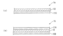
本発明に係るフィルム状封止材の一実施形態を図1(a)に示し、他の実施形態を図1(b)に示す。図1(a)に示すフィルム状封止材1aは、接着性樹脂層11Cと、接着性樹脂層11Cの一方の面(図1中では上面)に積層された水蒸気バリア性樹脂層12とからなる2層構造を有する。一方、図1(b)に示すフィルム状封止材1bは、水蒸気バリア性樹脂層12と、水蒸気バリア性樹脂層12の一方の面(図1中では上面)に積層された接着性樹脂層11Aと、水蒸気バリア性樹脂層12の他方の面(図1中では下面)に積層された接着性樹脂層11Bとからなる3層構造を有する。ただし、本発明はこれらに限定されるものではない。
One embodiment of a film-like sealing material according to the present invention is shown in FIG. 1 (a), and another embodiment is shown in FIG. 1 (b). A film-
以下、フィルム状封止材1aおよびフィルム状封止材1bを包括してフィルム状封止材1という場合があり、接着性樹脂層11A、接着性樹脂層11Bおよび接着性樹脂層11Cを包括して接着性樹脂層11という場合がある。
Hereinafter, the film-
(1)接着性樹脂層
接着性樹脂層11は、被着体に対して接着性を示す層であり、本実施形態では、フィルム状封止材1の両面または片面の最外層に設けられている。接着性樹脂層11は、単層であってもよく、複数層であってもよい。
(1) Adhesive resin layer Adhesive resin layer 11 is a layer which shows adhesiveness to an adherend, and is provided on the outermost layer on both sides or one side of film-shaped sealing material 1 in this embodiment. Yes. The adhesive resin layer 11 may be a single layer or a plurality of layers.
接着性樹脂層11は、酸変性ポリオレフィン系樹脂およびシラン変性ポリオレフィン系樹脂の少なくとも1種を含有する。酸変性ポリオレフィン系樹脂およびシラン変性ポリオレフィン系樹脂は、ガラス板や樹脂フィルム、あるいは樹脂フィルムに有機または無機の機能性層を形成したフィルム等に対して高い接着力を示す。特に、酸変性ポリオレフィン系樹脂は、ポリエチレンテレフタレート等の樹脂に対して、より高い接着力を示し、シラン変性ポリオレフィン系樹脂は、ガラスに対して、より高い接着力を示す。かかる酸変性ポリオレフィン系樹脂およびシラン変性ポリオレフィン系樹脂の少なくとも1種を含有する接着性樹脂層11を有するフィルム状封止材1は、ガラス板や樹脂フィルム等の被着体に対する接着性に優れるとともに、接着性樹脂層11と水蒸気バリア性樹脂層12との密着性にも優れたものとなっている。
The adhesive resin layer 11 contains at least one of an acid-modified polyolefin resin and a silane-modified polyolefin resin. The acid-modified polyolefin-based resin and the silane-modified polyolefin-based resin exhibit high adhesion to a glass plate, a resin film, or a film in which an organic or inorganic functional layer is formed on the resin film. In particular, the acid-modified polyolefin-based resin exhibits a higher adhesive force to a resin such as polyethylene terephthalate, and the silane-modified polyolefin-based resin exhibits a higher adhesive force to glass. The film-shaped sealing material 1 having the adhesive resin layer 11 containing at least one of the acid-modified polyolefin resin and the silane-modified polyolefin resin has excellent adhesion to an adherend such as a glass plate or a resin film. The adhesiveness between the adhesive resin layer 11 and the water vapor
また、接着性樹脂層11は、酸変性ポリオレフィン系樹脂およびシラン変性ポリオレフィン系樹脂の少なくとも1種を含有することにより、印加する熱量が比較的低くても、優れた熱接着性を発揮する。これにより、フィルム状封止材1は、ハンドリング性に優れたものとなっている。 Further, the adhesive resin layer 11 exhibits at least one of an acid-modified polyolefin resin and a silane-modified polyolefin resin, thereby exhibiting excellent thermal adhesiveness even when the amount of heat applied is relatively low. Thereby, the film-form sealing material 1 is excellent in handling property.
酸変性ポリオレフィン系樹脂とは、酸でグラフト変性したポリオレフィン系樹脂を意味し、例えば、ポリオレフィン系樹脂に不飽和カルボン酸を反応させ、カルボキシル基を導入(グラフト変性)したものが挙げられる。なお、本明細書において、不飽和カルボン酸とは、カルボン酸無水物の概念を含み、カルボキシル基とは、無水カルボキシル基の概念を含むものである。 The acid-modified polyolefin resin means a polyolefin resin graft-modified with an acid, and examples thereof include those obtained by reacting an unsaturated carboxylic acid with a polyolefin resin to introduce a carboxyl group (graft modification). In the present specification, the unsaturated carboxylic acid includes the concept of a carboxylic acid anhydride, and the carboxyl group includes the concept of an anhydrous carboxyl group.
上記ポリオレフィン系樹脂とは、重合体を構成するモノマー成分としてオレフィンを含む重合体(共重合体の概念を含む)をいい、モノマー成分が1種または2種以上のオレフィンのみからなる重合体であってもよいし、モノマー成分として1種または2種以上のオレフィンおよび他のモノマーを含む重合体(共重合体)であってもよい。 The polyolefin resin refers to a polymer (including the concept of a copolymer) containing olefin as a monomer component constituting the polymer, and the monomer component is a polymer composed of only one or two or more olefins. Alternatively, it may be a polymer (copolymer) containing one or more olefins and other monomers as monomer components.
上記オレフィンとしては、炭素数2〜8のα−オレフィンが好ましく、例えば、エチレン、プロピレン、ブチレン、イソブチレン、1−ヘキセン等が挙げられる。中でもエチレンおよびプロピレンが好ましく、特にエチレンが好ましい。上記他のモノマーとしては、本実施形態に係るフィルム状封止材1の目的を阻害しない限り特に限定されず、例えば、酢酸ビニル、(メタ)アクリル酸エステル等が挙げられる。なお、本明細書において、(メタ)アクリル酸とは、アクリル酸およびメタクリル酸の両方を意味する。他の類似用語も同様である。 As said olefin, a C2-C8 alpha olefin is preferable, for example, ethylene, propylene, butylene, isobutylene, 1-hexene etc. are mentioned. Of these, ethylene and propylene are preferable, and ethylene is particularly preferable. The other monomer is not particularly limited as long as the purpose of the film-shaped sealing material 1 according to the present embodiment is not impaired, and examples thereof include vinyl acetate and (meth) acrylic acid ester. In addition, in this specification, (meth) acrylic acid means both acrylic acid and methacrylic acid. The same applies to other similar terms.
上記ポリオレフィン系樹脂としては、具体的には、超低密度ポリエチレン(VLDPE,密度:880kg/m3以上、910kg/m3未満)、低密度ポリエチレン(LDPE,密度:910kg/m3以上、930kg/m3未満)、中密度ポリエチレン(MDPE,密度:930kg/m3以上、942kg/m3未満)、高密度ポリエチレン(HDPE,密度:942kg/m3以上)、直鎖状低密度ポリエチレン等のポリエチレン樹脂、ポリプロピレン樹脂(PP)、エチレン−プロピレン共重合体、オレフィン系エラストマー(TPO)、エチレン−酢酸ビニル共重合体(EVA)、エチレン−(メタ)アクリル酸共重合体、エチレン−(メタ)アクリル酸エステル共重合体などが挙げられる。これらは、1種を単独で、または2種以上を組み合わせて使用することができる。上記の中でも、超低密度ポリエチレン、低密度ポリエチレン、中密度ポリエチレン、高密度ポリエチレン、直鎖状低密度ポリエチレン等のポリエチレン樹脂が好ましく、特に超低密度ポリエチレンが好ましい。 As the polyolefin-based resin, specifically, ultra low density polyethylene (VLDPE, density: 880 kg / m 3 or more and less than 910 kg / m 3), low density polyethylene (LDPE, density: 910 kg / m 3 or more, 930 kg / m 3), medium density polyethylene (MDPE, density: 930 kg / m 3 or more, 942Kg / m 3), high density polyethylene (HDPE, density: 942kg / m 3 or higher), linear low density polyethylene, such as polyethylene Resin, polypropylene resin (PP), ethylene-propylene copolymer, olefin elastomer (TPO), ethylene-vinyl acetate copolymer (EVA), ethylene- (meth) acrylic acid copolymer, ethylene- (meth) acrylic Examples include acid ester copolymers. These can be used individually by 1 type or in combination of 2 or more types. Among these, polyethylene resins such as ultra-low density polyethylene, low density polyethylene, medium density polyethylene, high density polyethylene, and linear low density polyethylene are preferable, and ultra low density polyethylene is particularly preferable.
上記ポリオレフィン系樹脂に反応させる不飽和カルボン酸としては、例えば、マレイン酸、フマル酸、イタコン酸、シトラコン酸、グルタコン酸、テトラヒドロフタル酸、アコニット酸、無水マレイン酸、無水イタコン酸、無水グルタコン酸、無水シトラコン酸、無水アコニット酸、ノルボルネンジカルボン酸無水物、テトラヒドロフタル酸無水物、(メタ)アクリル酸等が挙げられる。これらは、1種を単独で、または2種以上を組み合わせて使用することができる。上記の中でも、特に接着力に優れる無水マレイン酸が好ましい。 Examples of the unsaturated carboxylic acid to be reacted with the polyolefin-based resin include maleic acid, fumaric acid, itaconic acid, citraconic acid, glutaconic acid, tetrahydrophthalic acid, aconitic acid, maleic anhydride, itaconic anhydride, glutaconic anhydride, Citraconic anhydride, aconitic anhydride, norbornene dicarboxylic acid anhydride, tetrahydrophthalic anhydride, (meth) acrylic acid and the like can be mentioned. These can be used individually by 1 type or in combination of 2 or more types. Among the above, maleic anhydride, which is particularly excellent in adhesive strength, is preferable.
上記酸変性ポリオレフィン系樹脂としては、無水マレイン酸変性ポリオレフィン系樹脂が好ましく、特に無水マレイン酸変性ポリエチレン樹脂が好ましい。 As the acid-modified polyolefin resin, maleic anhydride-modified polyolefin resin is preferable, and maleic anhydride-modified polyethylene resin is particularly preferable.
ポリオレフィン系樹脂に反応させる不飽和カルボン酸の量としては、ポリオレフィン系樹脂100質量部に対して、0.1〜5.0質量部であることが好ましく、特に0.2〜3.0質量部であることが好ましく、さらには0.2〜1.0質量部であることが好ましい。反応させる不飽和カルボン酸の量が上記の範囲にあることで、得られる酸変性ポリオレフィン系樹脂は、接着力に優れる。 The amount of the unsaturated carboxylic acid to be reacted with the polyolefin resin is preferably 0.1 to 5.0 parts by mass, particularly 0.2 to 3.0 parts by mass with respect to 100 parts by mass of the polyolefin resin. It is preferable that it is 0.2-1.0 mass part. When the amount of the unsaturated carboxylic acid to be reacted is in the above range, the resulting acid-modified polyolefin resin is excellent in adhesive strength.
酸変性ポリオレフィン系樹脂は、ビカット軟化点(Sp)が90℃以下であることが好ましく、特に30〜70℃であることが好ましく、さらには30〜60℃であることが好ましい。ビカット軟化点が30℃以上であると、室温においては接着性が発現しないため、フィルム状封止材1の取扱性に優れるため好ましい。また、ビカット軟化点が90℃以下であると、比較的短時間での熱圧着で接着が可能となるため、有機素子が熱圧着時の熱により劣化することを防止でき、有機EL素子を有する表示装置用モジュールや、電子ペーパー、有機薄膜太陽電池等の電子デバイスを効率よく製造することができる。なお、ビカット軟化点は、ASTM D1525に基づいて測定した値とする。 The acid-modified polyolefin-based resin preferably has a Vicat softening point (Sp) of 90 ° C. or less, particularly preferably 30 to 70 ° C., and more preferably 30 to 60 ° C. A Vicat softening point of 30 ° C. or higher is preferable because the adhesiveness is not expressed at room temperature, and the handleability of the film-shaped sealing material 1 is excellent. In addition, when the Vicat softening point is 90 ° C. or lower, it becomes possible to bond by thermocompression bonding in a relatively short time, so that the organic element can be prevented from being deteriorated by heat during thermocompression bonding, and has an organic EL element. Electronic devices such as modules for display devices, electronic paper, and organic thin-film solar cells can be efficiently manufactured. The Vicat softening point is a value measured based on ASTM D1525.
酸変性ポリオレフィン系樹脂は、190℃、荷重20.2Nにおけるメルトフローレート(MFR)が、0.5〜30g/10分であることが好ましく、特に1〜15g/10分であることが好ましく、さらには2〜10g/10分であることが好ましい。接着性樹脂層11を押出成形により形成する場合、MFRが0.5g/10分未満であると、押出成形が困難となるおそれがあり、MFRが30g/10分を超えると、押出成形により製膜した際に、厚み精度が低下するおそれがある。なお、本明細書におけるMFRは、ASTMD1238に基づいて測定した値とする。 The acid-modified polyolefin resin preferably has a melt flow rate (MFR) at 190 ° C. and a load of 20.2 N of 0.5 to 30 g / 10 minutes, particularly preferably 1 to 15 g / 10 minutes. Furthermore, it is preferable that it is 2-10 g / 10min. When the adhesive resin layer 11 is formed by extrusion molding, if the MFR is less than 0.5 g / 10 min, extrusion molding may be difficult. If the MFR exceeds 30 g / 10 min, it is manufactured by extrusion molding. When the film is formed, the thickness accuracy may decrease. In addition, MFR in this specification shall be the value measured based on ASTMD1238.
酸変性ポリオレフィン系樹脂は、市販品を用いることもできる。市販品としては、例えば、アドマー(登録商標)(三井化学社製)、BondyRam(Polyram社製)、orevac(登録商標)(ARKEMA社製)、モディック(登録商標)(三菱化学社製)等が挙げられる。 A commercially available product may be used as the acid-modified polyolefin resin. Examples of commercially available products include Admer (registered trademark) (manufactured by Mitsui Chemicals), BondyRam (manufactured by Polyram), orevac (registered trademark) (manufactured by ARKEMA), Modic (registered trademark) (manufactured by Mitsubishi Chemical Corporation), and the like. Can be mentioned.
シラン変性ポリオレフィン系樹脂とは、ポリオレフィン系樹脂に不飽和シラン化合物を反応させることにより、ポリオレフィン系樹脂をグラフト変性したものである。シラン変性ポリオレフィン系樹脂は、特に被着体がガラスの場合に強固に接着するため、好ましく用いられる。 The silane-modified polyolefin resin is obtained by graft-modifying a polyolefin resin by reacting an unsaturated silane compound with the polyolefin resin. The silane-modified polyolefin resin is preferably used because it adheres firmly particularly when the adherend is glass.
シラン変性ポリオレフィン系樹脂のポリオレフィン系樹脂としては、前述の酸でグラフト変性させるポリオレフィン系樹脂として例示したポリオレフィン系樹脂が挙げられる。 Examples of the polyolefin resin of the silane-modified polyolefin resin include the polyolefin resins exemplified as the polyolefin resin to be graft-modified with the above-mentioned acid.
シラン変性ポリオレフィン系樹脂は、シラン変性ポリエチレン樹脂およびシラン変性エチレン−酢酸ビニル共重合体が好ましく、特に、シラン変性低密度ポリエチレン、シラン変性超低密度ポリエチレン、シラン変性直鎖状低密度ポリエチレン等のシラン変性ポリエチレン樹脂が好ましい。 The silane-modified polyolefin-based resin is preferably a silane-modified polyethylene resin and a silane-modified ethylene-vinyl acetate copolymer, and particularly silanes such as silane-modified low-density polyethylene, silane-modified ultra-low-density polyethylene, and silane-modified linear low-density polyethylene. A modified polyethylene resin is preferred.
上記ポリオレフィン系樹脂に反応させる不飽和シラン化合物としては、ビニルシラン化合物が好ましく、例えば、ビニルトリメトキシシラン、ビニルトリエトキシシラン、ビニルトリプロポキシシラン、ビニルトリイソプロポキシシラン、ビニルトリブトキシシラン、ビニルトリペンチロキシシラン、ビニルトリフェノキシシラン、ビニルトリベンジルオキシシラン、ビニルトリメチレンジオキシシラン、ビニルトリエチレンジオキシシラン、ビニルプロピオニルオキシシラン、ビニルトリアセトキシシラン、ビニルトリカルボキシシラン等が挙げられる。これらは、1種を単独で、または2種以上を組み合わせて使用することができる。 As the unsaturated silane compound to be reacted with the polyolefin-based resin, a vinyl silane compound is preferable. For example, vinyl trimethoxy silane, vinyl triethoxy silane, vinyl tripropoxy silane, vinyl triisopropoxy silane, vinyl tributoxy silane, vinyl tripentyl. Examples include loxysilane, vinyltriphenoxysilane, vinyltribenzyloxysilane, vinyltrimethylenedioxysilane, vinyltriethylenedioxysilane, vinylpropionyloxysilane, vinyltriacetoxysilane, and vinyltricarboxysilane. These can be used individually by 1 type or in combination of 2 or more types.
ポリオレフィン系樹脂に反応させる不飽和シラン化合物の量としては、ポリオレフィン系樹脂100質量部に対して、0.1〜10質量部であることが好ましく、特に0.3〜7質量部であることが好ましく、さらには0.5〜5質量部であることが好ましい。反応させる不飽和シラン化合物の量が上記の範囲にあることで、得られるシラン変性ポリオレフィン系樹脂は、接着力に優れる。 The amount of the unsaturated silane compound to be reacted with the polyolefin resin is preferably 0.1 to 10 parts by mass, particularly 0.3 to 7 parts by mass with respect to 100 parts by mass of the polyolefin resin. More preferably, it is 0.5 to 5 parts by mass. When the amount of the unsaturated silane compound to be reacted is in the above range, the resulting silane-modified polyolefin resin is excellent in adhesive strength.
シラン変性ポリオレフィン系樹脂は、190℃、荷重20.2Nにおけるメルトフローレート(MFR)が、0.1〜30g/10分であることが好ましく、特に0.3〜15g/10分であることが好ましく、さらには0.5〜10g/10分であることが好ましい。接着性樹脂層11を押出成形により形成する場合、MFRが0.1g/10分未満であると、押出成形が困難となるおそれがあり、MFRが30g/10分を超えると、押出成形により製膜した際に、厚み精度が低下するおそれがある。 The silane-modified polyolefin-based resin preferably has a melt flow rate (MFR) at 190 ° C. and a load of 20.2 N of 0.1 to 30 g / 10 minutes, particularly 0.3 to 15 g / 10 minutes. More preferably, it is 0.5 to 10 g / 10 min. When the adhesive resin layer 11 is formed by extrusion molding, if the MFR is less than 0.1 g / 10 min, extrusion molding may be difficult. If the MFR exceeds 30 g / 10 min, the adhesive resin layer 11 is manufactured by extrusion molding. When the film is formed, the thickness accuracy may decrease.
シラン変性ポリオレフィン系樹脂は、市販品を用いることもできる。市販品としては、例えば、リンクロン(登録商標)(三菱化学社製)等が挙げられ、中でも、低密度ポリエチレン系のリンクロン、直鎖状低密度ポリエチレン系のリンクロン、超低密度ポリエチレン系のリンクロン、およびエチレン−酢酸ビニル共重合体系のリンクロンを好ましく使用することができる。 A commercial item can also be used for a silane modified polyolefin resin. Commercially available products include, for example, Linklon (registered trademark) (manufactured by Mitsubishi Chemical Corporation), among others, low density polyethylene-based linklon, linear low-density polyethylene-based linkron, and ultra-low-density polyethylene-based. Of these, Rincron of ethylene-vinyl acetate copolymer system can be preferably used.
接着性樹脂層11は、酸変性ポリオレフィン系樹脂・シラン変性ポリオレフィン系樹脂以外に、他の熱可塑性樹脂を含有してもよい。他の熱可塑性樹脂としては、例えば、酸変性またはシラン変性されていないポリオレフィン系樹脂、ポリエステル系樹脂、ポリウレタン系樹脂、ポリエステルウレタン系樹脂、アクリル系樹脂、アミド系樹脂、スチレン系樹脂、シラン系樹脂、ゴム系樹脂等が挙げられる。 The adhesive resin layer 11 may contain other thermoplastic resins in addition to the acid-modified polyolefin resin / silane-modified polyolefin resin. Other thermoplastic resins include, for example, non-acid-modified or silane-modified polyolefin resins, polyester resins, polyurethane resins, polyester urethane resins, acrylic resins, amide resins, styrene resins, silane resins. And rubber resins.
接着性樹脂層11は、酸変性ポリオレフィン系樹脂およびシラン変性ポリオレフィン系樹脂の少なくとも1種のみからなる(酸変性ポリオレフィン系樹脂およびシラン変性ポリオレフィン系樹脂の少なくとも1種を100質量%含有する)ことが好ましいが、上記の他の樹脂成分を含む場合、接着性樹脂層11は、酸変性ポリオレフィン系樹脂およびシラン変性ポリオレフィン系樹脂の少なくとも1種を50質量%以上含有することが好ましく、特に70質量%以上含有することが好ましい。 The adhesive resin layer 11 is composed of at least one of an acid-modified polyolefin resin and a silane-modified polyolefin resin (contains 100% by mass of at least one of an acid-modified polyolefin resin and a silane-modified polyolefin resin). Preferably, when the other resin component is included, the adhesive resin layer 11 preferably contains 50% by mass or more, particularly 70% by mass, of at least one of an acid-modified polyolefin resin and a silane-modified polyolefin resin. It is preferable to contain above.
なお、接着性樹脂層11は、上記樹脂以外に、所望により、例えば粘着付与剤、紫外線吸収剤、紫外線安定剤、帯電防止剤、顔料、難燃剤、可塑剤、滑剤、ブロッキング防止剤、シランカップリング剤等の各種添加剤等を含有してもよい。 The adhesive resin layer 11 is made of, for example, a tackifier, an ultraviolet absorber, an ultraviolet stabilizer, an antistatic agent, a pigment, a flame retardant, a plasticizer, a lubricant, an antiblocking agent, and a silane cup, if desired. You may contain various additives, such as a ring agent.
接着性樹脂層11の厚さは、1〜100μmであることが好ましく、特に3〜80μmであることが好ましく、さらには5〜50μmであることが好ましい。接着性樹脂層11の厚さが1μm未満であると、所望の接着性が得られないおそれがある。一方、接着性樹脂層11の厚さが100μmを超えると、フィルム状封止材1の厚さが厚くなり過ぎ、透過率やハンドリング性が低下するおそれがある。 The thickness of the adhesive resin layer 11 is preferably 1 to 100 μm, particularly preferably 3 to 80 μm, and further preferably 5 to 50 μm. If the thickness of the adhesive resin layer 11 is less than 1 μm, the desired adhesiveness may not be obtained. On the other hand, if the thickness of the adhesive resin layer 11 exceeds 100 μm, the thickness of the film-shaped sealing material 1 becomes too thick, and the transmittance and handling properties may be reduced.
また、フィルム状封止材1における接着性樹脂層11の厚さ(接着性樹脂層が複数ある場合には、その合計の厚さ)の割合は、フィルム状封止材1の厚さの5〜60%であることが好ましく、特に5〜50%であることが好ましく、さらには5〜40%であることが好ましい。接着性樹脂層11の厚さの割合が5%未満であると、所望の接着性が得られないおそれがある。一方、接着性樹脂層11の厚さの割合が60%を超えると、相対的に水蒸気バリア性樹脂層12の厚さが薄くなり過ぎて、所望の水蒸気バリア性が得られないおそれがある。
The ratio of the thickness of the adhesive resin layer 11 in the film-shaped sealing material 1 (the total thickness when there are a plurality of adhesive resin layers) is 5 of the thickness of the film-shaped sealing material 1. It is preferably ˜60%, particularly preferably 5 to 50%, further preferably 5 to 40%. If the ratio of the thickness of the adhesive resin layer 11 is less than 5%, the desired adhesiveness may not be obtained. On the other hand, if the ratio of the thickness of the adhesive resin layer 11 exceeds 60%, the water vapor
なお、接着性樹脂層が複数ある場合、接着性樹脂層の材料、厚さ等は、それぞれ同じであってもよいし、異なっていてもよい。 Note that when there are a plurality of adhesive resin layers, the material, thickness, and the like of the adhesive resin layers may be the same or different.
(2)水蒸気バリア性樹脂層
水蒸気バリア性樹脂層12は、フィルム状封止材1において水蒸気が透過することを防止・抑制するための樹脂層である。水蒸気バリア性樹脂層12は、単層であってもよく、複数層であってもよい。
(2) Water Vapor Barrier Resin Layer The water vapor
本実施形態における水蒸気バリア性樹脂層12は、エチレン−(メタ)アクリル酸共重合体、ゴム系樹脂およびアイオノマーから選ばれる少なくとも1種の熱可塑性樹脂(当該熱可塑性樹脂を「熱可塑性樹脂T」という場合がある。)を含有する。熱可塑性樹脂Tを含有することにより、水蒸気バリア性樹脂層12は、水蒸気バリア性に優れたものとなり、当該水蒸気バリア性樹脂層12を有するフィルム状封止材1も、水蒸気バリア性に優れたものとなる。また、水蒸気バリア性樹脂層12が上記のように熱可塑性樹脂Tを含有することにより、接着性樹脂層11との密着性が向上するとともに、フィルム状封止材1の熱圧着による封止を確実に行うことができる。
The water vapor
なお、上記水蒸気バリア性樹脂層12は、接着性を有するものであってもよい。水蒸気バリア性樹脂層12が接着性を有する場合、当該水蒸気バリア性樹脂層12は、後述する封止部材やガスバリアフィルムにも接着することができる。したがって、図1(a)に示すフィルム状封止材1aのように、接着性樹脂層11Cがガスバリア性樹脂層12の片面にのみ積層される場合でも、フィルム状封止材として使用することが可能である。
In addition, the said water vapor | steam
エチレン−(メタ)アクリル酸共重合体は、エチレンとアクリル酸および/またはメタクリル酸との共重合体であるが、特にエチレンとメタクリル酸との共重合体であるエチレン−メタクリル酸共重合体が好ましい。エチレン−(メタ)アクリル酸共重合体中における単量体単位としての(メタ)アクリル酸の含有量は、2〜20質量%であることが好ましく、特に3〜15質量%であることが好ましい。(メタ)アクリル酸の含有量が2質量%未満であると、樹脂の結晶化度が高くなり、不透明になるおそれがある。一方、(メタ)アクリル酸の含有量が20質量%を超えると、所望の水蒸気バリア性が得られないおそれがある。 The ethylene- (meth) acrylic acid copolymer is a copolymer of ethylene and acrylic acid and / or methacrylic acid. In particular, an ethylene-methacrylic acid copolymer which is a copolymer of ethylene and methacrylic acid is used. preferable. The content of (meth) acrylic acid as a monomer unit in the ethylene- (meth) acrylic acid copolymer is preferably 2 to 20% by mass, and particularly preferably 3 to 15% by mass. . When the content of (meth) acrylic acid is less than 2% by mass, the crystallinity of the resin becomes high and there is a possibility that the resin becomes opaque. On the other hand, if the content of (meth) acrylic acid exceeds 20% by mass, the desired water vapor barrier property may not be obtained.
アイオノマーとしては、例えば、オレフィン系アイオノマー、ウレタン系アイオノマー、スチレン系アイオノマー、フッ素系アイオノマー等が挙げられる。これらの中でも、水蒸気バリア性に優れるという点で、オレフィン系アイオノマーを用いることが好ましい。オレフィン系アイオノマーとしては、例えば、エチレン−(メタ)アクリル酸共重合体、エチレン−フマル酸共重合体、エチレン−マレイン酸共重合体、エチレン−マレイン酸モノメチル共重合体、エチレン−マレイン酸モノエチル共重合体等のオレフィン系樹脂の分子間を金属イオンで結合したものが挙げられる。金属イオンの金属としては、例えば、ナトリウム、リチウム等のアルカリ金属、亜鉛、マグネシウム、カルシウム等のアルカリ土類金属のような多価金属などが挙げられる。アイオノマーは、1種を単独でまたは2種以上を混合して使用することができる。 Examples of the ionomer include olefin-based ionomers, urethane-based ionomers, styrene-based ionomers, and fluorine-based ionomers. Among these, it is preferable to use an olefin ionomer in terms of excellent water vapor barrier properties. Examples of olefinic ionomers include ethylene- (meth) acrylic acid copolymers, ethylene-fumaric acid copolymers, ethylene-maleic acid copolymers, ethylene-monomethyl monomethyl copolymers, and ethylene-monoethyl maleate copolymers. The thing which couple | bonded between molecules of olefin resin, such as a polymer, with the metal ion is mentioned. Examples of the metal ion include alkali metals such as sodium and lithium, and polyvalent metals such as alkaline earth metals such as zinc, magnesium and calcium. An ionomer can be used individually by 1 type or in mixture of 2 or more types.
ゴム系樹脂としては、例えば、天然ゴム、天然ゴムに(メタ)アクリル酸アルキルエステル、スチレンおよび(メタ)アクリロニトリルから選ばれる1種又は2種以上の単量体をグラフト重合させた変性天然ゴム、ポリイソブチレン系樹脂、ブタジエンゴム、クロロプレンゴム、イソプレンゴム、ハロゲン化ブチルゴム、スチレン−ブタジエン共重合体(SBR)、スチレン−イソプレン共重合体、アクリロニトリル−ブタジエンの共重合体(ニトリルゴム)、メタクリル酸メチル−ブタジエン共重合体、ウレタンゴム、スチレン−1,3−ブタジエン−スチレンブロック共重合体(SBS)、スチレン−イソプレン−スチレンブロック共重合体(SIS)、エチレン−プロピレン−非共役ジエン三元共重合体等が挙げられる。これらのゴム系化合物は1種を単独で、あるいは2種以上を組み合わせて用いることができる。これらの中でも、ゴム系樹脂としては、ポリイソブチレン系樹脂を含むものが好ましい。 Examples of rubber resins include natural rubber, modified natural rubber obtained by graft polymerization of one or more monomers selected from (meth) acrylic acid alkyl ester, styrene and (meth) acrylonitrile on natural rubber, Polyisobutylene resin, butadiene rubber, chloroprene rubber, isoprene rubber, halogenated butyl rubber, styrene-butadiene copolymer (SBR), styrene-isoprene copolymer, acrylonitrile-butadiene copolymer (nitrile rubber), methyl methacrylate -Butadiene copolymer, urethane rubber, styrene-1,3-butadiene-styrene block copolymer (SBS), styrene-isoprene-styrene block copolymer (SIS), ethylene-propylene-nonconjugated diene ternary copolymer Examples include coalescence. These rubber compounds can be used singly or in combination of two or more. Among these, as the rubber resin, those containing a polyisobutylene resin are preferable.
水蒸気バリア性樹脂層12は、上記熱可塑性樹脂T以外に、他の樹脂成分を含有してもよい。他の樹脂成分としては、ポリエチレン、ポリプロピレン、ポリブテン、エチレン−αオレフィン共重合体、エチレン−酢酸ビニル共重合体、エチレン−(メタ)アクリル酸エステル共重合体等のオレフィン系樹脂(ただし、エチレン−(メタ)アクリル酸共重合体を除く。)、ウレタン系樹脂、ポリエステル系樹脂、ポリエステルウレタン系樹脂、アクリル系樹脂、アミド系樹脂、スチレン系樹脂、シラン系樹脂などが挙げられる。
In addition to the thermoplastic resin T, the water vapor
水蒸気バリア性樹脂層12は、熱可塑性樹脂Tのみからなる(熱可塑性樹脂Tを100質量%含有する)ことが好ましいが、上記の他の樹脂成分を含む場合、水蒸気バリア性樹脂層12は、熱可塑性樹脂Tを50質量%以上含有することが好ましく、特に60質量%以上含有することが好ましい。
The water vapor
水蒸気バリア性樹脂層12は、上記樹脂以外に、所望により、粘着付与剤、紫外線吸収剤、紫外線安定剤、帯電防止剤、顔料、難燃剤、可塑剤、滑剤、ブロッキング防止剤等の各種添加剤等を含有してもよい。
In addition to the above resins, the water vapor
水蒸気バリア性樹脂層12の厚さは、5〜300μmであることが好ましく、10〜200μmであることがより好ましく、特に15〜100μmであることが好ましく、さらには20〜50μmであることが好ましい。水蒸気バリア性樹脂層12の厚さが5μm未満であると、所望の水蒸気バリア性が得られないおそれがある。一方、水蒸気バリア性樹脂層12の厚さが300μmを超えると、フィルム状封止材1の厚さが厚くなり過ぎ、ハンドリング性が低下するおそれがある。
The thickness of the water vapor
また、フィルム状封止材1の厚さに対する水蒸気バリア性樹脂層12の厚さの割合は、フィルム状封止材1の厚さの10〜99%であることが好ましく、30〜95%であることがより好ましく、40〜90%であることが特に好ましく、50〜80%であることがさらに好ましい。なお、フィルム状封止材1の厚さについては、後述する。水蒸気バリア性樹脂層12の厚さの割合がフィルム状封止材1の厚さの10%未満であると、所望の水蒸気バリア性が得られないおそれがある。一方、水蒸気バリア性樹脂層12の厚さの割合がフィルム状封止材1の厚さの99%を超えると、第1および第2の接着性樹脂層11A,11Bが薄くなりすぎて、所望の接着性が得られないおそれがある。
Moreover, it is preferable that the ratio of the thickness of the water vapor | steam
(3)フィルム状封止材の物性等
フィルム状封止材1の厚さは、7〜500μmであることが好ましく、特に15〜400μmであることが好ましく、さらには20〜200μmであることが好ましい。フィルム状封止材1の厚さが7μm未満であると、所望の水蒸気バリア性および/または接着性が得られないおそれがある。一方、フィルム状封止材1の厚さが500μmを超えると、フィルム状封止材1の厚さが不要に厚くなり、例えば電子デバイスに使用したときに、電子デバイスの厚さが厚くなり過ぎるおそれがある。
(3) Physical properties of film-like sealing material The thickness of the film-like sealing material 1 is preferably 7 to 500 μm, particularly preferably 15 to 400 μm, and more preferably 20 to 200 μm. preferable. If the thickness of the film-shaped sealing material 1 is less than 7 μm, the desired water vapor barrier property and / or adhesiveness may not be obtained. On the other hand, when the thickness of the film-shaped sealing material 1 exceeds 500 μm, the thickness of the film-shaped sealing material 1 becomes unnecessarily thick. For example, when used for an electronic device, the thickness of the electronic device becomes too thick. There is a fear.
フィルム状封止材1は、当該フィルム状封止材1の厚みを50μmとしたときに、温度40℃、相対湿度90%RHの環境下における水蒸気透過率が、15g/m2・day以下であることが好ましく、特に12g/m2・day以下であることが好ましく、さらには10g/m2・day以下であることが好ましい。フィルム状封止材1の水蒸気透過率が15g/m2・day以下であると、外部からの水蒸気が、当該フィルム状封止材1で効果的にブロックされて、封止対象物に到達することが防止・抑制され、封止対象物が水分の悪影響を受け難くなる。本実施形態に係るフィルム状封止材1では、上記熱可塑性樹脂Tを含有する水蒸気バリア性樹脂層12を備えることにより、上記のような水蒸気透過率を達成することができる。なお、水蒸気透過率の値は、フィルム状封止材1の厚みから換算して求めることができる。例えば、厚みがAμmで、水蒸気透過率がBg/(m2・day)のフィルム状封止材の場合、厚みが50μmのときの水蒸気透過率は、B×A/50という式に当てはめて換算して求めることができる。
The film-shaped sealing material 1 has a water vapor transmission rate of 15 g / m 2 · day or less in an environment of a temperature of 40 ° C. and a relative humidity of 90% RH when the thickness of the film-shaped sealing material 1 is 50 μm. Preferably, it is preferably 12 g / m 2 · day or less, more preferably 10 g / m 2 · day or less. When the water vapor transmission rate of the film-shaped sealing material 1 is 15 g / m 2 · day or less, water vapor from the outside is effectively blocked by the film-shaped sealing material 1 and reaches the object to be sealed. This is prevented / suppressed, and the sealing object is hardly affected by moisture. In the film-shaped sealing material 1 which concerns on this embodiment, the above water vapor permeability can be achieved by providing the water vapor
フィルム状封止材1は、接着性樹脂層11(フィルム状封止材1bの場合は、接着性樹脂層11Aおよび接着性樹脂層11Bのいずれか一方)を120℃でガラス板に貼り合わせた際の、当該ガラス板に対する接着力が、3N/25mm以上であることが好ましく、特に5N/25mm以上であることが好ましく、さらには10N/25mm以上であることが好ましい。接着力が3N/25mm以上であることで、封止対象物を確実に封止し、ガラス板や樹脂フィルム等の被着体との間で、浮きや剥がれ等が発生することを防止することができる。なお、接着力の測定方法は、後述する試験例に示す通りである。本実施形態に係るフィルム状封止材1は、上記酸変性ポリオレフィン系樹脂およびシラン変性ポリオレフィン系樹脂の少なくとも1種を含有する接着性樹脂層11を備えることにより、上記のような接着力を達成することができる。
The film-shaped sealing material 1 was obtained by bonding an adhesive resin layer 11 (in the case of the film-shaped
フィルム状封止材1が、液晶素子、発光ダイオード(LED素子)、有機エレクトロルミネッセンス(有機EL)素子等を有する表示装置用モジュール、電子ペーパー、太陽電池モジュールなどの電子デバイスに使用される場合、フィルム状封止材1は、可視光領域における全光線透過率が85%以上であることが好ましく、特に88%以上であることが好ましく、さらには90%以上であることが好ましい。接着性樹脂層11および水蒸気バリア性樹脂層12が前述した材料からなることにより、フィルム状封止材1は、上記の全光線透過率が可能となる。なお、全光線透過率は、JIS K7361:1996に準拠して測定した値とする。
When the film-shaped sealing material 1 is used for an electronic device such as a liquid crystal element, a light emitting diode (LED element), a module for a display device having an organic electroluminescence (organic EL) element, electronic paper, a solar cell module, The film-like sealing material 1 preferably has a total light transmittance in the visible light region of 85% or more, particularly preferably 88% or more, and more preferably 90% or more. When the adhesive resin layer 11 and the water vapor
(4)フィルム状封止材の製造方法
フィルム状封止材1は、常法によって製造することができる。例えば、図1(b)に示す3層構造のフィルム状封止材1bの場合、接着性樹脂層11Aと、水蒸気バリア性樹脂層12と、接着性樹脂層11Bとを、その順で積層されるように共押出成形する方法、接着性樹脂層11Aとしての単層のフィルム(第1の接着性樹脂フィルム)および接着性樹脂層11Bとしての単層のフィルム(第2の接着性樹脂フィルム)をそれぞれ用意し、第1の接着性樹脂フィルムに水蒸気バリア性樹脂層12を形成した後、当該水蒸気バリア性樹脂層12に第2の接着性樹脂フィルムを積層する方法、水蒸気バリア性樹脂層12としての単層のフィルム(水蒸気バリア性樹脂フィルム)を用意し、その水蒸気バリア性樹脂フィルムの両面に、接着性樹脂層11A,11Bを形成する方法、第1の接着性樹脂フィルムと、水蒸気バリア性樹脂フィルムと、第2の接着性樹脂フィルムとを用意し、それら3枚の樹脂フィルムをその順で重ねて積層する方法などの方法によって、フィルム状封止材1を製造することができる。また、剥離シート上に、接着性樹脂層11A,11Bをそれぞれ形成し、接着性樹脂層付きの剥離シートをそれぞれ用意し、あらかじめ用意した水蒸気バリア性樹脂フィルムの両面に、接着性樹脂層付きの剥離シートを積層する方法によって、フィルム状封止材1を製造することもできる。
(4) Manufacturing method of film-shaped sealing material The film-shaped sealing material 1 can be manufactured by a conventional method. For example, in the case of the film-shaped
なお、接着性樹脂層11A,11Bとしての単層のフィルム(第1の接着性樹脂フィルム,第2の接着性樹脂フィルム)、水蒸気バリア性樹脂層12としての単層のフィルム(水蒸気バリア性樹脂フィルム)を形成する方法としては、特に限定されず、溶融押出法、カレンダー法、乾式法、溶液法などが例示される。溶液法の場合には、上述した各層を構成する樹脂を有機溶剤に溶解した溶液を、公知の塗布方法により塗布し、得られた塗膜を適宜乾燥することで各層を形成すればよい。
In addition, the single layer film (1st adhesive resin film, 2nd adhesive resin film) as the
接着性樹脂層11A,11B(第1の接着性樹脂フィルム,第2の接着性樹脂フィルム)と水蒸気バリア性樹脂層12(水蒸気バリア性樹脂フィルム)とを積層する際には、加熱しながら積層することが好ましい。加熱温度は、接着性樹脂層11A,11B(第1の接着性樹脂フィルム,第2の接着性樹脂フィルム)が軟化する温度以上であることが好ましい。
When laminating the
図1(a)に示す2層構造のフィルム状封止材1aの場合も、上記3層構造のフィルム状封止材1bの場合と同様の方法により製造することができる。
Also in the case of the film-shaped
(5)フィルム状封止材の用途
本実施形態に係るフィルム状封止材1は、水蒸気バリア性および接着性に優れるため、電子デバイスにおける電子素子の封止に好適に使用することができる。具体的には、液晶素子、発光ダイオード(LED素子)、有機エレクトロルミネッセンス(有機EL)素子等を有する表示装置用モジュール、電子ペーパー、太陽電池モジュールなどが挙げられる。中でも、有機EL素子を有する表示装置用モジュール(有機ELモジュール)や電子ペーパーにおいては、高い接着性および水蒸気バリア性が求められているため、本実施形態に係るフィルム状封止材1を好適に使用することができる。なお、本実施形態に係るフィルム状封止材1を用いて電子素子を封止する方法については、後述の電子デバイスの項で説明する。
(5) Use of film-shaped sealing material Since the film-shaped sealing material 1 which concerns on this embodiment is excellent in water vapor | steam barrier property and adhesiveness, it can be used conveniently for sealing of the electronic element in an electronic device. Specifically, a module for a display device having a liquid crystal element, a light emitting diode (LED element), an organic electroluminescence (organic EL) element, an electronic paper, a solar cell module, and the like can be given. Among these, in the module for display devices (organic EL module) and electronic paper having an organic EL element, high adhesiveness and water vapor barrier properties are required. Therefore, the film-like sealing material 1 according to this embodiment is preferably used. Can be used. In addition, the method of sealing an electronic element using the film-form sealing material 1 which concerns on this embodiment is demonstrated by the term of the below-mentioned electronic device.
〔電子デバイス用封止シート〕
本発明に係る電子デバイス用封止シート(以下「封止シート」という場合がある。)の一実施形態を図2(a)に示し、他の実施形態を図2(b)に示す。図2(a)に示す封止シート2aは、図1(a)に示すフィルム状封止材1aと、フィルム状封止材1aの水蒸気バリア性樹脂層12側に積層されたガスバリアフィルム21とを備える。一方、図2(b)に示す封止シート2bは、図1(b)に示すフィルム状封止材1bと、フィルム状封止材1bの一方の接着性樹脂層11Aに積層されたガスバリアフィルム21とを備える。以下、封止シート2aおよび封止シート2bを包括して封止シート2という場合がある。
[Seal sheet for electronic devices]
One embodiment of an encapsulating sheet for electronic devices (hereinafter sometimes referred to as “encapsulating sheet”) according to the present invention is shown in FIG. 2A, and another embodiment is shown in FIG. The sealing
ガスバリアフィルム21は、水蒸気、酸素等のガスを透過させ難い特性を有するフィルムである。また、封止シート2を、表示装置用モジュール、電子ペーパー、太陽電池モジュール、後述のトップエミッション型の電子デバイスなどの透明性が必要とされる用途に用いる場合は、ガスバリアフィルム21は透明である必要がある。ガスバリアフィルム21としては、基材フィルムとガスバリア層との積層体が好ましい。このようなガスバリアフィルム21としては、例えば、基材フィルムの片面または両面に、直接またはその他の層を介してガスバリア層を形成したもの、基材フィルムの中間にガスバリア層を設けたものなどを使用することができる。なかでも、ガスバリアフィルム21は、基材フィルムの片面または両面に、直接またはその他の層を介してガスバリア層を形成したものが好ましい。
The
基材フィルムとしては、例えば、ポリエチレン、ポリプロピレン、エチレン−(メタ)アクリル酸共重合体、エチレン−(メタ)アクリル酸エステル共重合体等のポリオレフィン、ポリエチレンテレフタレート、ポリブチレンテレフタレート等のポリエステル、ポリ塩化ビニル、ポリスチレン、ポリウレタン、ポリカーボネート、ポリアミド、ポリイミド、ポリスルフォン、ポリエーテルスルフォン、ポリフェニレンスルフィド、ポリアリレート、ポリメタクリル酸メチル等のアクリル系樹脂、ポリブテン、ポリブタジエン、ポリメチルペンテン、エチレン酢酸ビニル共重合体、ABS樹脂、アイオノマー樹脂などの樹脂からなるフィルム、またはそれらの積層フィルム等が挙げられる。それらの中でも、強度の観点から、ポリエチレンテレフタレート、ポリブチレンテレフタレート等のポリエステル、ポリカーボネート、ポリアミド、ポリイミド、ポリスルフォン、ポリエーテルスルフォン、ポリフェニレンスルフィド、ポリアリレートなどからなるフィルムが好ましい。基材フィルムは、延伸フィルムであってもよいし、無延伸フィルムであってもよい。また、基材フィルムは、紫外線吸収剤等の各種添加剤を含んだものであってもよい。 Examples of the base film include polyolefin such as polyethylene, polypropylene, ethylene- (meth) acrylic acid copolymer, ethylene- (meth) acrylic acid ester copolymer, polyester such as polyethylene terephthalate and polybutylene terephthalate, polychlorinated Acrylic resins such as vinyl, polystyrene, polyurethane, polycarbonate, polyamide, polyimide, polysulfone, polyethersulfone, polyphenylene sulfide, polyarylate, polymethyl methacrylate, polybutene, polybutadiene, polymethylpentene, ethylene vinyl acetate copolymer, Examples thereof include a film made of a resin such as an ABS resin or an ionomer resin, or a laminated film thereof. Among these, from the viewpoint of strength, a film made of polyester such as polyethylene terephthalate and polybutylene terephthalate, polycarbonate, polyamide, polyimide, polysulfone, polyethersulfone, polyphenylene sulfide, polyarylate and the like is preferable. The base film may be a stretched film or an unstretched film. Further, the base film may contain various additives such as an ultraviolet absorber.
基材フィルムの厚さは、1〜500μmであることが好ましく、特に5〜300μmであることが好ましく、さらには10〜100μmであることが好ましい。 The thickness of the base film is preferably 1 to 500 μm, particularly preferably 5 to 300 μm, and more preferably 10 to 100 μm.
ガスバリア層は、基材フィルムにガスバリア性を付与することを目的として積層される。ガスバリア層の材料としては、ガスバリアフィルム21のガスバリア性を所望のレベルにすることができるものであれば、特に限定されることはない。ガスバリア層の材料としては、例えば、酸化ケイ素、酸窒化ケイ素、酸化アルミニウム、酸窒化アルミニウム、酸化マグネシウム、酸化亜鉛、酸化インジウム、酸化スズ等の無機酸化物、窒化ケイ素、窒化アルミニウム等の無機窒化物、酸化窒化ケイ素等の無機酸化窒化物等、アルミニウム、マグネシウム、亜鉛、スズ等の金属などが挙げられる。これらは、1種を単独で、または2種以上を組み合わせて使用することができる。
The gas barrier layer is laminated for the purpose of imparting gas barrier properties to the base film. The material of the gas barrier layer is not particularly limited as long as the gas barrier property of the
また、ガスバリア層は、ポリシラザン化合物を公知の方法によりシリカ質膜に転化させたものであってもよい。さらに、ガスバリア層は、ポリシラザン化合物、ポリカルボシラン化合物、ポリシラン化合物、ポリオルガノシロキサン化合物、テトラオルガノシラン化合物等のケイ素化合物を含む層にプラズマイオン注入して得られる層であってもよい。プラズマイオン注入にて注入されるイオンとしては、例えば、アルゴン、ヘリウム、ネオン、クリプトン、キセノン等の希ガス、フルオロカーボン、水素、窒素、酸素、二酸化炭素、塩素、フッ素、硫黄等のイオン;金、銀、銅、白金、ニッケル、パラジウム、クロム、チタン、モリブデン、ニオブ、タンタル、タングステン、アルミニウム等の金属のイオンなどが挙げられる。 Further, the gas barrier layer may be one obtained by converting a polysilazane compound into a siliceous film by a known method. Further, the gas barrier layer may be a layer obtained by plasma ion implantation into a layer containing a silicon compound such as a polysilazane compound, a polycarbosilane compound, a polysilane compound, a polyorganosiloxane compound, or a tetraorganosilane compound. Examples of ions implanted by plasma ion implantation include rare gases such as argon, helium, neon, krypton, and xenon, ions such as fluorocarbon, hydrogen, nitrogen, oxygen, carbon dioxide, chlorine, fluorine, and sulfur; gold, Examples include ions of metals such as silver, copper, platinum, nickel, palladium, chromium, titanium, molybdenum, niobium, tantalum, tungsten, and aluminum.
ガスバリア層の厚さは、1nm〜10μmであることが好ましく、10〜1000nmであることがより好ましく、20〜500nmであることが特に好ましく、50〜200nmであることがさらに好ましい。 The thickness of the gas barrier layer is preferably 1 nm to 10 μm, more preferably 10 to 1000 nm, particularly preferably 20 to 500 nm, and further preferably 50 to 200 nm.
ガスバリア層は、単層であってもよく、複数層であってもよいが、より高いガスバリア性が得られるという観点から、ガスバリア層は複数層であることが好ましい。 The gas barrier layer may be a single layer or a plurality of layers, but the gas barrier layer is preferably a plurality of layers from the viewpoint of obtaining higher gas barrier properties.
ガスバリア層を形成する方法は、使用する材料に応じて適宜選択すればよい。例えば、上記ガスバリア層の材料を、蒸着法、スパッタリング法、イオンプレーティング法、熱CVD法、プラズマCVD法等により基材フィルム上に形成する方法、あるいは上記ガスバリア層の材料を有機溶剤に溶解した溶液を、基材フィルムに塗布する方法などが挙げられる。 The method for forming the gas barrier layer may be appropriately selected according to the material to be used. For example, the gas barrier layer material is formed on a base film by vapor deposition, sputtering, ion plating, thermal CVD, plasma CVD, or the like, or the gas barrier layer material is dissolved in an organic solvent. The method of apply | coating a solution to a base film is mentioned.
ガスバリアフィルム21の水蒸気透過率は、40℃、90%RHにおいて、0.5g/m2・day以下であることが好ましく、特に0.1g/m2・day以下であることが好ましく、さらには0.05g/m2・day以下であることが好ましい。
The water vapor permeability of the
封止シート2を製造するには、フィルム状封止材1とガスバリアフィルム21とを重ね合わせて積層すればよい。なお、封止シート2aを製造する場合には、フィルム状封止材1aの水蒸気バリア性樹脂層12と、ガスバリアフィルム21とを重ね合わせて積層することが好ましい。ガスバリアフィルム21がその片面にガスバリア層を有する場合、ガスバリア層がフィルム状封止材1側となるように、ガスバリアフィルム21とフィルム状封止材1とを積層することが好ましい。また、フィルム状封止材1とガスバリアフィルム21とは、直接積層されていてもよく、その他の層を介して積層されていてもよい。
In order to manufacture the sealing sheet 2, the film-like sealing material 1 and the
フィルム状封止材1とガスバリアフィルム21とを積層する際には、加熱しながら積層することが好ましい。加熱温度は、フィルム状封止材1の接着性樹脂層11(図2(b)中では接着性樹脂層11A)が軟化する温度以上であることが好ましい。
When laminating the film-shaped sealing material 1 and the
本実施形態に係る封止シート2は、前述したフィルム状封止材1の用途と同様の用途に用いることができ、特に、高い接着性および水蒸気バリア性が求められる有機EL素子等を有する表示装置用モジュール、電子ペーパー、太陽電池モジュールなどの電子デバイスにおける電子素子の封止に好適に使用することができる。封止シート2を用いて封止を行う場合、ガスバリアフィルム21が積層された側とは反対側の接着性樹脂層11(図2(a)中では接着性樹脂層11C、図2(b)中では接着性樹脂層11B)と被着体とを熱圧着することで、封止することができる。
The sealing sheet 2 according to the present embodiment can be used for the same application as that of the film-shaped sealing material 1 described above, and particularly has a display having an organic EL element or the like that requires high adhesion and water vapor barrier properties. It can use suitably for sealing of the electronic element in electronic devices, such as an apparatus module, electronic paper, and a solar cell module. When sealing is performed using the sealing sheet 2, the adhesive resin layer 11 on the side opposite to the side on which the
〔電子デバイス〕
本発明の一実施形態に係る電子デバイスは、上述した実施形態に係るフィルム状封止材1bによって封止されている。本実施形態に係る電子デバイス3Aは、具体的には、図3に示すように、基板31と、基板31上に形成された電子素子32と、電子素子32を封止するフィルム状封止材1bと、フィルム状封止材1bの電子素子32とは反対側に積層された封止部材33とを備える。封止部材33としては、特に制限はなく、例えばガラス板等が挙げられる。
[Electronic device]
The electronic device according to one embodiment of the present invention is sealed with the film-shaped
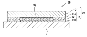
また、本発明の他の実施形態に係る電子デバイスは、上述した実施形態に係る封止シート2bによって封止されている。本実施形態に係る電子デバイス3Bは、具体的には、図4に示すように、基板31と、基板31上に形成された電子素子32と、電子素子32を封止する封止シート2bとを備える。なお、封止シート2bは、フィルム状封止材1bと当該フィルム状封止材1bの片面に積層されたガスバリアフィルム21との積層体である。
Moreover, the electronic device which concerns on other embodiment of this invention is sealed with the sealing
なお、図示はしないが、本発明の別の実施形態に係る電子デバイスとして、電子デバイス3Aにおいて、フィルム状封止材1bの替わりにフィルム状封止材1aによって封止された電子デバイスや、電子デバイス3Bにおいて、封止シート2bの替わりに封止シート2aによって封止された電子デバイスも例示することができる。
Although not shown, as an electronic device according to another embodiment of the present invention, in the
これらの電子デバイス3A,3Bは、例えば、電子素子32として液晶素子、LED素子、有機EL素子等を有する表示装置用モジュール、電子素子32として電気泳動型素子、電子粉粒体型素子、コレステリック液晶素子等を有する電子ペーパー、電子素子32として太陽電池セルを有する太陽電池モジュールなどであるが、これらに限定されるものではない。また、電子デバイス3A,3Bは、トップエミッション型の電子デバイスであってもよいし、ボトムエミッション型の電子デバイスであってもよい。例えば、電子デバイス3A,3Bがボトムエミッション型のデバイスである場合には、基板31は、透明基板であることが好ましい。また、電子デバイス3A,3Bがトップエミッション型の電子デバイスである場合には、封止部材33およびガスバリアフィルム21は、透明であることが好ましい。
These
基板31としては、電子デバイス3A,3Bの種類に応じて適宜選択されるが、例えば、ガラス板や樹脂フィルムが好ましく挙げられる。ガラス板の材料としては、例えば、無アルカリガラス、ソーダライムガラス、鉛ガラス、アルミノケイ酸ガラス、ホウケイ酸ガラス、バリウムホウケイ酸ガラス、バリウム・ストロンチウム含有ガラス、石英等からなる無機ガラス、ハイブリッドガラス等が挙げられる。基板31として用いられる樹脂フィルムとしては、例えば、ガスバリアフィルム21で例示した基材フィルムが挙げられる。
The
基板31の厚さは、電子デバイス3A,3Bの種類に応じて適宜設定される。
The thickness of the
電子デバイス3Aを製造する方法は特に限定されない。例えば、まず常法によって基板31上に電子素子32を形成する。その後、当該電子素子32を覆うようにして、フィルム状封止材1を載置し、さらにフィルム状封止材1の上にガラス板等の封止部材33を載置し、それらを熱圧着して電子素子32を封止することで電子デバイス3Aを製造することができる。なお、あらかじめ、フィルム状封止材1と封止部材33とを貼り合わせた積層体を得て、この積層体と電子素子32とを熱圧着して電子デバイス3Aを製造してもよい。
The method for manufacturing the
一方、電子デバイス3Bを製造する方法についても特に限定されない。例えば、基板31上に形成された電子素子32を覆うようにして、フィルム状封止材1が電子素子32側となるように封止シート2を載置し、それらを熱圧着して貼り合わせ、電子素子32を封止することで電子デバイス3Bを製造することができる。
On the other hand, the method for manufacturing the
封止は、常圧で行ってもよいし、加圧しながら行ってもよく、減圧雰囲気で行ってもよく、またはこれらを組み合わせて行ってもよい。また、フィルム状封止材1と電子素子32とを貼り合わせる際には、加熱する(熱圧着する)ことが好ましく、加熱することにより、フィルム状封止材1と電子素子32、基板31、および封止部材33またはガスバリアフィルム21とが強固に接着する。
Sealing may be performed at normal pressure, may be performed while applying pressure, may be performed in a reduced pressure atmosphere, or may be performed in combination. Moreover, when bonding the film-form sealing material 1 and the
貼り合わせる時の加熱温度は、通常、接着性樹脂層11が軟化する温度以上であることが好ましい。本実施形態における接着性樹脂層11は、酸変性ポリオレフィン系樹脂およびシラン変性ポリオレフィン系樹脂の少なくとも1種を含有することで、比較的短時間で熱圧着した場合でも優れた熱接着性を発揮する。具体的には、接着性樹脂層11が軟化する温度で貼り合わせ、数秒〜数分間(例えば1秒〜5分)、熱圧着することで封止することができる。このように、本実施形態に係るフィルム状封止材1は、電子デバイスの生産性に優れたものとなっている。 Usually, the heating temperature at the time of bonding is preferably equal to or higher than the temperature at which the adhesive resin layer 11 is softened. The adhesive resin layer 11 according to the present embodiment contains at least one of an acid-modified polyolefin resin and a silane-modified polyolefin resin, and thus exhibits excellent thermal adhesion even when thermocompression bonded in a relatively short time. . Specifically, it can be sealed by bonding at a temperature at which the adhesive resin layer 11 is softened and thermocompression bonding for several seconds to several minutes (for example, 1 second to 5 minutes). Thus, the film-form sealing material 1 which concerns on this embodiment is excellent in the productivity of an electronic device.
本実施形態に係る電子デバイス3A,3Bにおいては、電子素子32が、本実施形態に係るフィルム状封止材1で覆われているため、外部からの水蒸気が、フィルム状封止材1の水蒸気バリア性樹脂層12によってブロックされて、電子素子32に到達することが防止・抑制されるため、電子素子32が水分の悪影響を受け難いものとなっている。また、フィルム状封止材1は接着力に優れた接着性樹脂層11を備えているため、フィルム状封止材1と基板31、フィルム状封止材1と電子素子32、フィルム状封止材1と封止部材33、フィルム状封止材1とガスバリアフィルム21とは強固に接着し、それらの間で浮きや剥がれ等が発生したり、それらの間に水蒸気が浸入したりすることが防止・抑制されている。さらには、フィルム状封止材1は、接着性樹脂層11と水蒸気バリア性樹脂層12との間で層間剥離することが防止・抑制されている。
In the
以上説明した実施形態は、本発明の理解を容易にするために記載されたものであって、本発明を限定するために記載されたものではない。したがって、上記実施形態に開示された各要素は、本発明の技術的範囲に属する全ての設計変更や均等物をも含む趣旨である。 The embodiment described above is described for facilitating understanding of the present invention, and is not described for limiting the present invention. Therefore, each element disclosed in the above embodiment is intended to include all design changes and equivalents belonging to the technical scope of the present invention.
例えば、接着性樹脂層11は、水蒸気バリア性樹脂層12に、その他の層を介して積層されていてもよい。また、接着性樹脂層11上には、剥離シートが積層されていてもよい。なお、剥離シートは、接着性樹脂層を形成する時に利用されたり、接着性樹脂層を保護する目的で設けられ、フィルム状封止材1を使用する際には剥離される。
For example, the adhesive resin layer 11 may be laminated on the water vapor
以下、実施例等により本発明をさらに具体的に説明するが、本発明の範囲はこれらの実施例等に限定されるものではない。 EXAMPLES Hereinafter, although an Example etc. demonstrate this invention further more concretely, the scope of the present invention is not limited to these Examples etc.
〔実施例1〕
<フィルム状封止材の作製>
表1に示す接着性樹脂層および水蒸気バリア性樹脂層を構成する材料を、押出機(東洋精機製作所社製)によって共押出成形し、厚さ10μmの第1の接着性樹脂層と、厚さ30μmの水蒸気バリア性樹脂層と、厚さ10μmの第2の接着性樹脂層とをその順で積層してなるフィルム状封止材(図1(b)に示す構成)を製造した。なお、第1の接着性樹脂層および第2の接着性樹脂層は、両方とも同じ接着性樹脂を構成する材料を用いた。
[Example 1]
<Production of film-like encapsulant>
The materials constituting the adhesive resin layer and the water vapor barrier resin layer shown in Table 1 were coextruded by an extruder (manufactured by Toyo Seiki Seisakusho Co., Ltd.), and the first adhesive resin layer having a thickness of 10 μm and the thickness A film-like sealing material (configuration shown in FIG. 1B) was produced by laminating a 30 μm water vapor barrier resin layer and a 10 μm thick second adhesive resin layer in that order. In addition, the material which comprises the same adhesive resin was used for both the 1st adhesive resin layer and the 2nd adhesive resin layer.
<ガスバリアフィルムの作製>
基材としてのポリエチレンテレフタレートフィルム(東洋紡績社製,コスモシャインA4100,厚さ50μm)上に、ポリシラザン化合物(ペルヒドロポリシラザンを主成分とするコーティング材,クラリアントジャパン社製,アクアミカNL110−20)をスピンコート法により塗布し、120℃で1分間加熱して、厚さ150nmの、ペルヒドロポリシラザンを含むポリシラザン層を形成した。次に、プラズマイオン注入装置を用いて、ポリシラザン層の表面に、下記の条件にてアルゴンをプラズマイオン注入してガスバリア層を形成し、ガスバリアフィルムAを作製した。
<Production of gas barrier film>
On a polyethylene terephthalate film (Toyobo Co., Ltd., Cosmo Shine A4100, thickness 50 μm) as a base material, a polysilazane compound (a coating material mainly composed of perhydropolysilazane, Clariant Japan Co., Ltd., Aquamica NL110-20) is spun. It was applied by a coating method and heated at 120 ° C. for 1 minute to form a polysilazane layer containing perhydropolysilazane having a thickness of 150 nm. Next, using a plasma ion implantation apparatus, argon was ion-implanted on the surface of the polysilazane layer under the following conditions to form a gas barrier layer, thereby producing a gas barrier film A.
上記のガスバリア層を形成するために用いたプラズマイオン注入装置及びプラズマイオン注入条件は以下の通りである。
〔プラズマイオン注入装置〕
RF電源:日本電子社製,型番号「RF」56000
高電圧パルス電源:栗田製作所社製,「PV−3−HSHV−0835」
〔プラズマイオン注入条件〕
プラズマ生成ガス:Ar
ガス流量:100sccm
Duty比:0.5%
印加電圧:−15kV
RF電源:周波数 13.56MHz,印加電力 1000W
チャンバー内圧:0.2Pa
パルス幅:5μsec
処理時間(イオン注入時間):200秒
The plasma ion implantation apparatus and the plasma ion implantation conditions used for forming the gas barrier layer are as follows.
[Plasma ion implantation system]
RF power supply: manufactured by JEOL Ltd., model number “RF” 56000
High-voltage pulse power supply: “PV-3-HSHV-0835” manufactured by Kurita Manufacturing Co., Ltd.
[Plasma ion implantation conditions]
Plasma generation gas: Ar
Gas flow rate: 100sccm
Duty ratio: 0.5%
Applied voltage: -15 kV
RF power supply: frequency 13.56 MHz, applied power 1000 W
Chamber internal pressure: 0.2 Pa
Pulse width: 5μsec
Processing time (ion implantation time): 200 seconds
<封止シートAの作製>
得られたフィルム状封止材とガスバリアフィルムAとを、120℃で加熱しながら貼り合わせて、封止シートAを得た。
<Preparation of sealing sheet A>
The obtained film-shaped sealing material and the gas barrier film A were bonded together while heating at 120 ° C. to obtain a sealing sheet A.
<封止シートBの作製>
一方、得られたフィルム状封止材とガスバリアフィルムB(厚み7μmのアルミニウム箔(ガスバリア層)の両面に、厚み12μmのポリエチレンテレフタレートシートをウレタン系接着剤層で接着した積層フィルム,アジヤアルミ社製)を、120℃で加熱しながら貼り合わせて、封止シートBを得た。
<Preparation of sealing sheet B>
On the other hand, the obtained film-shaped encapsulant and gas barrier film B (laminated film made by Aya Aluminum Co., Ltd.) having a 12 μm thick polyethylene terephthalate sheet bonded to both sides of a 7 μm thick aluminum foil (gas barrier layer) with a urethane adhesive layer Were bonded together while heating at 120 ° C. to obtain a sealing sheet B.
<トップエミッション型の電子デバイスの製造>
下記の方法により、ガラス基板上に陰極、発光層および陽極をこの順で積層し、電子素子(有機EL素子)を形成した。
<Manufacture of top emission type electronic devices>
By the following method, the cathode, the light emitting layer, and the anode were laminated | stacked in this order on the glass substrate, and the electronic element (organic EL element) was formed.
まず、ガラス基板を溶媒洗浄およびUV/オゾン処理で洗浄した後、アルミニウム(Al)(高純度化学研究所社製)を0.1nm/sの速度で100nm蒸着させて陰極を形成した。 First, the glass substrate was cleaned by solvent cleaning and UV / ozone treatment, and then aluminum (Al) (manufactured by High Purity Chemical Laboratory) was deposited to a thickness of 100 nm at a rate of 0.1 nm / s to form a cathode.
得られた陰極(Al膜)上に、(8−ヒドロキシ−キノリノレート)リチウム(Luminescence Technology社製)を10nm、2,9−ジメチル−4,7−ジフェニル−1,10−フェナントロリン(Luminescence Technology社製)を10nm、トリス(8−ヒドロキシ−キノリネート)アルミニウム(Luminescence Technology社製)を40nm、N,N’−ビス(ナフタレン−1−イル)−N,N’−ビス(フェニル)−ベンジデン)(Luminescence Technology社製)を60nm、0.1〜0.2nm/sの速度で順次蒸着させ、発光層を形成した。 On the obtained cathode (Al film), (8-hydroxy-quinolinolate) lithium (manufactured by Luminescence Technology) was added to 10 nm, 2,9-dimethyl-4,7-diphenyl-1,10-phenanthroline (manufactured by Luminescence Technology). ) 10 nm, tris (8-hydroxy-quinolinate) aluminum (made by Luminescence Technology) 40 nm, N, N′-bis (naphthalen-1-yl) -N, N′-bis (phenyl) -benzidene) (Luminescence) Technology) was sequentially deposited at a rate of 60 nm and 0.1 to 0.2 nm / s to form a light emitting layer.
得られた発光層上に、酸化インジウムスズ(ITO)膜(厚さ:100nm、シート抵抗:50Ω/□)をスパッタリング法により形成して陽極を作製し、有機EL素子を得た。なお、蒸着時の真空度は、全て1×10−4Pa以下であった。 On the obtained light emitting layer, an indium tin oxide (ITO) film (thickness: 100 nm, sheet resistance: 50Ω / □) was formed by sputtering to produce an anode, whereby an organic EL device was obtained. In addition, all the vacuum degrees at the time of vapor deposition were 1 * 10 <-4> Pa or less.
一方、上記封止シートAを、窒素雰囲気下で、ホットプレートを用いて120℃で30分間加熱して乾燥し、封止シートA中に含まれる水分を除去した後、そのまま放置して室温まで冷却した。そして、ガラス基板上に形成された有機EL素子を覆うように、フィルム状封止材が有機EL素子側になるように封止シートAを載置し、それらを100℃で熱圧着して有機EL素子を封止し、トップエミッション型の電子デバイスを得た。 On the other hand, the sealing sheet A is dried by heating at 120 ° C. for 30 minutes using a hot plate in a nitrogen atmosphere to remove moisture contained in the sealing sheet A, and then left as it is to room temperature. Cooled down. And the sealing sheet A is mounted so that a film-form sealing material may become the organic EL element side so that the organic EL element formed on the glass substrate may be covered, and they are thermocompression-bonded at 100 degreeC, and organic The EL element was sealed to obtain a top emission type electronic device.
<ボトムエミッション型の電子デバイスの製造>
下記の方法により、ガラス基板上に陽極、発光層および陰極をこの順で積層し、電子素子(有機EL素子)を形成した。
<Manufacture of bottom emission type electronic devices>
By the following method, an anode, a light emitting layer, and a cathode were laminated in this order on a glass substrate to form an electronic element (organic EL element).
まず、ガラス基板の表面に酸化インジウムスズ(ITO)膜(厚さ:150nm、シート抵抗:30Ω/□)をスパッタリング法により形成し、次いで、溶媒洗浄およびUV/オゾン処理を行うことで陽極を作製した。 First, an indium tin oxide (ITO) film (thickness: 150 nm, sheet resistance: 30Ω / □) is formed on the surface of the glass substrate by sputtering, and then an anode is prepared by solvent cleaning and UV / ozone treatment. did.
得られた陽極(ITO膜)上に、N,N’−ビス(ナフタレン−1−イル)−N,N’−ビス(フェニル)−ベンジデン)(Luminescence Technology社製)を60nm、トリス(8−ヒドロキシ−キノリネート)アルミニウム(Luminescence Technology社製)を40nm、2,9−ジメチル−4,7−ジフェニル−1,10−フェナントロリン(Luminescence Technology社製)を10nm、(8−ヒドロキシ−キノリノレート)リチウム(Luminescence Technology社製)を10nm、0.1〜0.2nm/sの速度で順次蒸着させ、発光層を形成した。 On the obtained anode (ITO film), N, N′-bis (naphthalen-1-yl) -N, N′-bis (phenyl) -benzidene) (manufactured by Luminescence Technology) 60 nm, Tris (8- Hydroxy-quinolinate) Aluminum (manufactured by Luminescence Technology) 40 nm, 2,9-dimethyl-4,7-diphenyl-1,10-phenanthroline (manufactured by Luminescence Technology) 10 nm, (8-hydroxy-quinolinolate) lithium (Luminescence) Technology) was sequentially deposited at a rate of 10 nm and 0.1 to 0.2 nm / s to form a light emitting layer.
得られた発光層上に、アルミニウム(Al)(高純度化学研究所社製)を0.1nm/sの速度で100nm蒸着させて陰極を形成し、有機EL素子を得た。なお、蒸着時の真空度は、全て1×10−4Pa以下であった。 On the obtained light-emitting layer, aluminum (Al) (manufactured by Kojundo Chemical Laboratory Co., Ltd.) was deposited to a thickness of 100 nm at a rate of 0.1 nm / s to form a cathode, whereby an organic EL device was obtained. In addition, all the vacuum degrees at the time of vapor deposition were 1 * 10 <-4> Pa or less.
一方、上記封止シートBを、窒素雰囲気下で、ホットプレートを用いて120℃で30分間加熱して、封止シートB中に含まれる水分を除去した後、そのまま放置して室温まで冷却した。そして、ガラス基板上に形成された有機EL素子を覆うように、フィルム状封止材が有機EL素子側になるように封止シートBを載置し、それらを100℃で熱圧着して有機EL素子を封止し、ボトムエミッション型の電子デバイスを得た。 On the other hand, the sealing sheet B was heated at 120 ° C. for 30 minutes using a hot plate in a nitrogen atmosphere to remove moisture contained in the sealing sheet B, and then left to cool to room temperature. . And the sealing sheet B is mounted so that a film-form sealing material may become the organic EL element side so that the organic EL element formed on the glass substrate may be covered, and they are thermocompression-bonded at 100 degreeC, and organic The EL element was sealed to obtain a bottom emission type electronic device.
〔実施例2〜4,比較例1〜2〕
接着性樹脂層および水蒸気バリア性樹脂層を構成する材料を表1に示すように変更する以外、実施例1と同様にしてフィルム状封止材を製造した。このフィルム状封止材を使用して、実施例1と同様にして封止シートA,Bを作製し、トップエミッション型およびボトムエミッション型の電子デバイスを得た。
[Examples 2-4, Comparative Examples 1-2]
A film-like sealing material was produced in the same manner as in Example 1 except that the materials constituting the adhesive resin layer and the water vapor barrier resin layer were changed as shown in Table 1. Using this film-shaped encapsulant, encapsulating sheets A and B were produced in the same manner as in Example 1 to obtain top emission type and bottom emission type electronic devices.
〔実施例5〜7〕
表1に示す接着性樹脂層および水蒸気バリア性樹脂層を構成する材料を、押出機(東洋精機製作所社製)によって共押出成形し、厚さ10μmの接着性樹脂層と、厚さ40μmの水蒸気バリア性樹脂層とをその順で積層してなるフィルム状封止材(図1(a)に示す構成)を製造した。次いで、得られたフィルム状封止材の水蒸気バリア性樹脂層側と、実施例1で使用したガスバリアフィルムAまたはガスバリアフィルムBとを、120℃で加熱しながら貼り合わせて封止シートA,Bを作製し、実施例1と同様にしてトップエミッション型およびボトムエミッション型の電子デバイスを得た。
[Examples 5 to 7]
The materials constituting the adhesive resin layer and the water vapor barrier resin layer shown in Table 1 are coextruded by an extruder (manufactured by Toyo Seiki Seisakusho Co., Ltd.), and the adhesive resin layer having a thickness of 10 μm and the water vapor having a thickness of 40 μm are used. A film-shaped sealing material (configuration shown in FIG. 1A) obtained by laminating a barrier resin layer in that order was produced. Next, the water vapor barrier resin layer side of the obtained film-shaped encapsulant and the gas barrier film A or gas barrier film B used in Example 1 were bonded together while heating at 120 ° C., and the sealing sheets A and B The top emission type and bottom emission type electronic devices were obtained in the same manner as in Example 1.
〔比較例3〜4〕
表1に示す接着性樹脂層を構成する材料を、押出機(東洋精機製作所社製)により押出成形して、厚さ50μmの単層の接着性樹脂フィルムを製膜した。この接着性樹脂フィルムをフィルム状封止材として使用して、実施例1と同様にして封止シートA,Bを作製し、トップエミッション型およびボトムエミッション型の電子デバイスを得た。
[Comparative Examples 3 to 4]
The material constituting the adhesive resin layer shown in Table 1 was extruded using an extruder (manufactured by Toyo Seiki Seisakusho Co., Ltd.) to form a single-layer adhesive resin film having a thickness of 50 μm. Using this adhesive resin film as a film-like sealing material, sealing sheets A and B were produced in the same manner as in Example 1 to obtain top emission type and bottom emission type electronic devices.
なお、表1に記載の略号等の詳細は以下の通りである。
[接着性樹脂層]
・AdmerSF731:無水マレイン酸変性ポリエチレン系樹脂(三井化学社製,商品名「AdmerSF731」,ビカット軟化点:43℃,190℃・荷重20.2NにおけるMFR:2.6g/10分)
・リンクロンXLE815N:シラン変性直鎖状低密度ポリエチレン(三菱化学社製,商品名「リンクロンXLE815N」,190℃・荷重20.2NにおけるMFR:0.5g/10分)
[水蒸気バリア性樹脂層]
・ニュクレルN1207C:エチレン−メタクリル酸共重合体(三井−デュポンポリケミカル社製,商品名「ニュクレルN1207C」)
・ハイミラン1650:エチレン系アイオノマー(Znタイプ)(三井−デュポンポリケミカル社製,商品名「ハイミラン1650」)
・Oppanol B50:イソブチレンのみからなる単独重合体(BASF社製,商品名「Oppanol B50」)
・エボリューSP90100:超低密度ポリエチレン(プライムポリマー社製,商品名「エボリューSP90100」)
Details of the abbreviations and the like described in Table 1 are as follows.
[Adhesive resin layer]
Admer SF731: Maleic anhydride-modified polyethylene resin (Mitsui Chemicals, trade name “Admer SF731”, Vicat softening point: 43 ° C., 190 ° C., MFR at load 20.2 N: 2.6 g / 10 min)
・ Linkron XLE815N: Silane-modified linear low-density polyethylene (Mitsubishi Chemical Co., Ltd., trade name “Linklon XLE815N”, MFR at 190 ° C. and load 20.2 N: 0.5 g / 10 min)
[Water vapor barrier resin layer]
Nucleel N1207C: ethylene-methacrylic acid copolymer (Mitsui-DuPont Polychemical Co., Ltd., trade name “Nucleel N1207C”)
・ High Milan 1650: Ethylene-based ionomer (Zn type) (Mitsui-Dupont Polychemical Co., Ltd., trade name “Hi Milan 1650”)
-Opanol B50: Homopolymer consisting only of isobutylene (manufactured by BASF, trade name “Opanol B50”)
Evolue SP90100: Ultra-low density polyethylene (manufactured by Prime Polymer Co., Ltd., trade name “Evolue SP90100”)
〔試験例1〕(水蒸気透過率の測定)
実施例または比較例で得られたフィルム状封止材(厚み50μm)の水蒸気透過率を測定した。具体的には、LYSSY社製の透過率測定機「L80−5000」を用い、40℃、90%RHの条件で測定を行った。結果を表1に示す。
[Test Example 1] (Measurement of water vapor transmission rate)
The water vapor transmission rate of the film-like sealing material (thickness 50 μm) obtained in the examples or comparative examples was measured. Specifically, the measurement was performed under the conditions of 40 ° C. and 90% RH using a transmittance measuring device “L80-5000” manufactured by LYSSY. The results are shown in Table 1.
〔試験例2〕(接着力の測定)
実施例または比較例で得られた封止シートBの接着性樹脂層を、被着体としてのガラス板(ソーダライムガラス,日本板硝子社製)と重ね合わせ、120℃で5分間加熱しながら貼り合わせて、試験片を得た。
[Test Example 2] (Measurement of adhesive strength)
The adhesive resin layer of the sealing sheet B obtained in the example or the comparative example is overlaid on a glass plate (soda lime glass, manufactured by Nippon Sheet Glass Co., Ltd.) as an adherend, and bonded while heating at 120 ° C. for 5 minutes. Together, a test piece was obtained.
得られた試験片を、貼り合わせ後24時間、23℃、50%RHの環境下で放置した後、同環境下で、引張試験機(オリエンテック社製,テンシロン)を用いて、剥離速度300mm/分、剥離角度180°の条件で剥離試験を行い、接着力(N/25mm)を測定した。結果を表1に示す。 The obtained test piece was allowed to stand in an environment of 23 ° C. and 50% RH for 24 hours after being bonded, and then in that environment, using a tensile tester (manufactured by Orientec, Tensilon), a peeling rate of 300 mm. / Min, a peel test was performed under the conditions of a peel angle of 180 °, and the adhesive strength (N / 25 mm) was measured. The results are shown in Table 1.
〔試験例3〕(電子デバイスの評価)
実施例または比較例で得られたトップエミッション型およびボトムエミッション型の電子デバイスを、23℃、50%RHの環境下で50時間放置した後、有機EL素子を起動させ、ダークスポット(非発光箇所)の有無を観察し、以下の基準で評価した。結果を表1に示す。
A:ダークスポットが発光面積の5%未満
B:ダークスポットが発光面積の5%以上10%未満
C:ダークスポットが発光面積の10%以上90%未満
[Test Example 3] (Evaluation of electronic device)
After leaving the top emission type and bottom emission type electronic devices obtained in the examples or comparative examples in an environment of 23 ° C. and 50% RH for 50 hours, the organic EL element is activated and dark spots (non-light emitting points) ) Was observed and evaluated according to the following criteria. The results are shown in Table 1.
A: Dark spot is less than 5% of light emission area B: Dark spot is 5% or more and less than 10% of light emission area C: Dark spot is 10% or more and less than 90% of light emission area

表1から分かるように、実施例で得られたフィルム状封止材は、水蒸気バリア性および接着性に優れていた。また、実施例で得られたフィルム状封止材によって封止された有機EL素子は、ダークスポットがほとんど見られず、電子デバイスの性能が良好であった。一方、比較例のフィルム状封止材は、水蒸気バリア性が劣っていたため、当該フィルム状封止材によって封止された有機EL素子は、ダークスポットが多く見られ、電子デバイスの性能が劣っていた。 As can be seen from Table 1, the film-like encapsulants obtained in the examples were excellent in water vapor barrier properties and adhesiveness. Moreover, the organic EL element sealed with the film-form sealing material obtained in the Example showed almost no dark spots, and the performance of the electronic device was good. On the other hand, since the film-form sealing material of the comparative example was inferior in water vapor | steam barrier property, the organic EL element sealed with the said film-form sealing material has many dark spots, and the performance of an electronic device is inferior. It was.
本発明に係る電子デバイス用フィルム状封止材および電子デバイス用封止シートは、例えば有機ELモジュールや電子ペーパーに好適に用いられる。また、本発明に係る電子デバイスは、例えば有機ELモジュールや電子ペーパーとして好適である。 The film-shaped sealing material for electronic devices and the sealing sheet for electronic devices according to the present invention are suitably used for, for example, an organic EL module and electronic paper. The electronic device according to the present invention is suitable as an organic EL module or electronic paper, for example.
1a,1b…電子デバイス用フィルム状封止材
11A,11B,11C…接着性樹脂層
12…水蒸気バリア性樹脂層
2a,2b…電子デバイス用封止シート
21…ガスバリアフィルム
3A,3B…電子デバイス
31…基板
32…電子素子
33…封止部材
DESCRIPTION OF
Claims (10)
水蒸気が透過することを防止または抑制する水蒸気バリア性樹脂層と
を備えた電子デバイス用フィルム状封止材であって、
前記接着性樹脂層は、酸変性ポリオレフィン系樹脂およびシラン変性ポリオレフィン系樹脂の少なくとも1種を含有し、
前記水蒸気バリア性樹脂層は、エチレン−(メタ)アクリル酸共重合体、ポリイソブチレン系樹脂およびアイオノマーから選ばれる少なくとも1種の熱可塑性樹脂を60質量%以上含有する
ことを特徴とする電子デバイス用フィルム状封止材。 An adhesive resin layer showing adhesion to the adherend,
A film-like encapsulant for electronic devices, comprising a water vapor barrier resin layer that prevents or suppresses the transmission of water vapor,
The adhesive resin layer contains at least one of an acid-modified polyolefin resin and a silane-modified polyolefin resin,
The water vapor barrier resin layer contains 60% by mass or more of at least one thermoplastic resin selected from an ethylene- (meth) acrylic acid copolymer, a polyisobutylene resin, and an ionomer. Film-like encapsulant.
前記電子デバイス用フィルム状封止材の片面に積層されたガスバリアフィルムと
を備えたことを特徴とする電子デバイス用封止シート。 A film-shaped encapsulant for electronic devices according to any one of claims 1 to 7,
The sealing sheet for electronic devices provided with the gas barrier film laminated | stacked on the single side | surface of the said film-form sealing material for electronic devices.
Priority Applications (1)
| Application Number | Priority Date | Filing Date | Title |
|---|---|---|---|
| JP2014013746A JP6144635B2 (en) | 2013-01-31 | 2014-01-28 | Film-shaped sealing material for electronic device, sealing sheet for electronic device, and electronic device |
Applications Claiming Priority (3)
| Application Number | Priority Date | Filing Date | Title |
|---|---|---|---|
| JP2013017306 | 2013-01-31 | ||
| JP2013017306 | 2013-01-31 | ||
| JP2014013746A JP6144635B2 (en) | 2013-01-31 | 2014-01-28 | Film-shaped sealing material for electronic device, sealing sheet for electronic device, and electronic device |
Publications (2)
| Publication Number | Publication Date |
|---|---|
| JP2014166753A JP2014166753A (en) | 2014-09-11 |
| JP6144635B2 true JP6144635B2 (en) | 2017-06-07 |
Family
ID=51616726
Family Applications (1)
| Application Number | Title | Priority Date | Filing Date |
|---|---|---|---|
| JP2014013746A Active JP6144635B2 (en) | 2013-01-31 | 2014-01-28 | Film-shaped sealing material for electronic device, sealing sheet for electronic device, and electronic device |
Country Status (1)
| Country | Link |
|---|---|
| JP (1) | JP6144635B2 (en) |
Families Citing this family (3)
| Publication number | Priority date | Publication date | Assignee | Title |
|---|---|---|---|---|
| JP7080216B2 (en) * | 2017-03-03 | 2022-06-03 | リンテック株式会社 | Gas barrier adhesive film, electronic members and optical members |
| TWI777082B (en) | 2018-08-16 | 2022-09-11 | 南韓商Lg化學股份有限公司 | Encapsulation film, organic electronic device comprising the same, and method for manufacturing an organic electronic device using the same |
| JP7645363B2 (en) * | 2020-08-19 | 2025-03-13 | トーレ・アドバンスド・マテリアルズ・コリア・インコーポレーテッド | Organic/inorganic adhesive composition and gas barrier film containing same |
Family Cites Families (8)
| Publication number | Priority date | Publication date | Assignee | Title |
|---|---|---|---|---|
| JPH02253952A (en) * | 1989-03-28 | 1990-10-12 | Daicel Chem Ind Ltd | Moistureproof film for el element |
| JPH07115220A (en) * | 1993-10-15 | 1995-05-02 | Kanegafuchi Chem Ind Co Ltd | Sealing sheet, solar cell and solar cell module using the same |
| JP2011077172A (en) * | 2009-09-29 | 2011-04-14 | Toppan Printing Co Ltd | Sealing material sheet and solar battery module |
| EP2615144B1 (en) * | 2010-09-07 | 2018-10-17 | Lintec Corporation | Adhesive sheet and electronic device |
| JP2012076291A (en) * | 2010-09-30 | 2012-04-19 | Dainippon Printing Co Ltd | Gas barrier film laminate, and packaging bag |
| JP5593215B2 (en) * | 2010-12-24 | 2014-09-17 | 三菱樹脂株式会社 | Multilayer body for solar cell and solar cell module manufactured using the same |
| JP2012216805A (en) * | 2011-03-25 | 2012-11-08 | Sekisui Chem Co Ltd | Solar cell module filler sheet |
| JP2012222247A (en) * | 2011-04-12 | 2012-11-12 | Kaneka Corp | Solar cell sealing material and solar cell module using the same |
-
2014
- 2014-01-28 JP JP2014013746A patent/JP6144635B2/en active Active
Also Published As
| Publication number | Publication date |
|---|---|
| JP2014166753A (en) | 2014-09-11 |
Similar Documents
| Publication | Publication Date | Title |
|---|---|---|
| JP6061707B2 (en) | Film-shaped sealing material for electronic device, sealing sheet for electronic device, and electronic device | |
| JP5997043B2 (en) | Film-like sealing material, sealing sheet, and electronic device | |
| TWI603844B (en) | Electronic equipment, film packaging materials, packaging films and electronic equipment | |
| JP6734955B2 (en) | Adhesive sheet, electronic device and manufacturing method thereof | |
| JP6061706B2 (en) | Film-shaped sealing material for electronic device, sealing sheet for electronic device, and electronic device | |
| CN104718263B (en) | Adhesive composition and bonding sheet | |
| US20170047548A1 (en) | Resin composition for sealing organic electronic device element, resin sheet for sealing organic electronic device element, organic electroluminescent element, and image display apparatus | |
| KR20150138261A (en) | Element-sealing resin composition for organic electronic device, element-sealing resin sheet for organic electronic device, organic electroluminescence element, and image display apparatus | |
| JP6468810B2 (en) | Film-like sealing material, sealing sheet, and electronic device | |
| WO2016056625A1 (en) | Film-form sealant, sealing sheet, and electronic device | |
| JP6144635B2 (en) | Film-shaped sealing material for electronic device, sealing sheet for electronic device, and electronic device | |
| JP2016087791A (en) | Film-like encapsulating material, encapsulating sheet and electronic device | |
| TWI594885B (en) | Film packaging materials, packaging films and electronic equipment | |
| WO2014119551A1 (en) | Film-shaped sealing material, sealing sheet, and electronic device | |
| JP2016078260A (en) | Film-like sealing material, sealing sheet, and electronic device | |
| WO2014119566A1 (en) | Film-shaped sealing material, sealing sheet, and electronic device | |
| JP6530900B2 (en) | Film-like sealing material, sealing sheet and electronic device | |
| JP2014148077A (en) | Film-like sealing material, sealing sheet and electronic device | |
| JP2016078261A (en) | Film-like sealing material, sealing sheet, and electronic device | |
| KR20170069202A (en) | Sealing material composition, sealing sheet, member for electronic device, and electronic device | |
| JP2012076289A (en) | Gas barrier film laminate, and packaging bag |
Legal Events
| Date | Code | Title | Description |
|---|---|---|---|
| A621 | Written request for application examination |
Free format text: JAPANESE INTERMEDIATE CODE: A621 Effective date: 20160113 |
|
| A977 | Report on retrieval |
Free format text: JAPANESE INTERMEDIATE CODE: A971007 Effective date: 20161128 |
|
| A131 | Notification of reasons for refusal |
Free format text: JAPANESE INTERMEDIATE CODE: A131 Effective date: 20161206 |
|
| A521 | Request for written amendment filed |
Free format text: JAPANESE INTERMEDIATE CODE: A523 Effective date: 20170131 |
|
| TRDD | Decision of grant or rejection written | ||
| A01 | Written decision to grant a patent or to grant a registration (utility model) |
Free format text: JAPANESE INTERMEDIATE CODE: A01 Effective date: 20170509 |
|
| A61 | First payment of annual fees (during grant procedure) |
Free format text: JAPANESE INTERMEDIATE CODE: A61 Effective date: 20170511 |
|
| R150 | Certificate of patent or registration of utility model |
Ref document number: 6144635 Country of ref document: JP Free format text: JAPANESE INTERMEDIATE CODE: R150 |
|
| R250 | Receipt of annual fees |
Free format text: JAPANESE INTERMEDIATE CODE: R250 |
|
| R250 | Receipt of annual fees |
Free format text: JAPANESE INTERMEDIATE CODE: R250 |
|
| R250 | Receipt of annual fees |
Free format text: JAPANESE INTERMEDIATE CODE: R250 |
|
| R250 | Receipt of annual fees |
Free format text: JAPANESE INTERMEDIATE CODE: R250 |
|
| R250 | Receipt of annual fees |
Free format text: JAPANESE INTERMEDIATE CODE: R250 |
|
| R250 | Receipt of annual fees |
Free format text: JAPANESE INTERMEDIATE CODE: R250 |