JP6143764B2 - Apparatus, system and method for measuring blood pressure gradient - Google Patents
Apparatus, system and method for measuring blood pressure gradient Download PDFInfo
- Publication number
- JP6143764B2 JP6143764B2 JP2014537792A JP2014537792A JP6143764B2 JP 6143764 B2 JP6143764 B2 JP 6143764B2 JP 2014537792 A JP2014537792 A JP 2014537792A JP 2014537792 A JP2014537792 A JP 2014537792A JP 6143764 B2 JP6143764 B2 JP 6143764B2
- Authority
- JP
- Japan
- Prior art keywords
- sensor
- valve
- pressure
- optical
- sensors
- Prior art date
- Legal status (The legal status is an assumption and is not a legal conclusion. Google has not performed a legal analysis and makes no representation as to the accuracy of the status listed.)
- Active
Links
- 238000000034 method Methods 0.000 title claims description 79
- 230000036772 blood pressure Effects 0.000 title claims description 64
- 230000003287 optical effect Effects 0.000 claims description 108
- 238000005259 measurement Methods 0.000 claims description 69
- 239000013307 optical fiber Substances 0.000 claims description 54
- 210000002216 heart Anatomy 0.000 claims description 50
- 230000000747 cardiac effect Effects 0.000 claims description 41
- 210000001765 aortic valve Anatomy 0.000 claims description 39
- 239000010410 layer Substances 0.000 claims description 36
- 210000003709 heart valve Anatomy 0.000 claims description 31
- 210000004204 blood vessel Anatomy 0.000 claims description 29
- 210000005240 left ventricle Anatomy 0.000 claims description 23
- 210000000709 aorta Anatomy 0.000 claims description 15
- 230000008878 coupling Effects 0.000 claims description 15
- 238000010168 coupling process Methods 0.000 claims description 15
- 238000005859 coupling reaction Methods 0.000 claims description 15
- 210000004115 mitral valve Anatomy 0.000 claims description 15
- 210000003102 pulmonary valve Anatomy 0.000 claims description 13
- 210000000591 tricuspid valve Anatomy 0.000 claims description 13
- 238000011144 upstream manufacturing Methods 0.000 claims description 11
- 210000005241 right ventricle Anatomy 0.000 claims description 8
- 239000011247 coating layer Substances 0.000 claims description 6
- 210000005245 right atrium Anatomy 0.000 claims description 6
- 210000005246 left atrium Anatomy 0.000 claims description 5
- 210000005242 cardiac chamber Anatomy 0.000 claims description 3
- 210000001147 pulmonary artery Anatomy 0.000 claims description 3
- 230000008569 process Effects 0.000 claims description 2
- 230000002861 ventricular Effects 0.000 description 22
- 239000008280 blood Substances 0.000 description 20
- 210000004369 blood Anatomy 0.000 description 20
- 239000012530 fluid Substances 0.000 description 19
- 230000017531 blood circulation Effects 0.000 description 18
- 239000000835 fiber Substances 0.000 description 18
- 208000031481 Pathologic Constriction Diseases 0.000 description 17
- 230000036262 stenosis Effects 0.000 description 17
- 208000037804 stenosis Diseases 0.000 description 17
- 210000001367 artery Anatomy 0.000 description 14
- 238000009530 blood pressure measurement Methods 0.000 description 14
- 229920000642 polymer Polymers 0.000 description 12
- 238000012544 monitoring process Methods 0.000 description 11
- 230000000694 effects Effects 0.000 description 10
- 238000010586 diagram Methods 0.000 description 9
- 239000003550 marker Substances 0.000 description 9
- 230000002526 effect on cardiovascular system Effects 0.000 description 8
- 206010002906 aortic stenosis Diseases 0.000 description 7
- 238000003745 diagnosis Methods 0.000 description 6
- 230000002093 peripheral effect Effects 0.000 description 6
- 238000012800 visualization Methods 0.000 description 6
- 238000002583 angiography Methods 0.000 description 5
- 239000000463 material Substances 0.000 description 5
- 230000008439 repair process Effects 0.000 description 5
- 210000003462 vein Anatomy 0.000 description 5
- 239000004642 Polyimide Substances 0.000 description 4
- 230000003213 activating effect Effects 0.000 description 4
- 230000001174 ascending effect Effects 0.000 description 4
- 230000008859 change Effects 0.000 description 4
- 229940079593 drug Drugs 0.000 description 4
- 239000003814 drug Substances 0.000 description 4
- 238000005516 engineering process Methods 0.000 description 4
- 208000019622 heart disease Diseases 0.000 description 4
- 230000000004 hemodynamic effect Effects 0.000 description 4
- 230000003902 lesion Effects 0.000 description 4
- 210000004072 lung Anatomy 0.000 description 4
- 238000004519 manufacturing process Methods 0.000 description 4
- 238000002324 minimally invasive surgery Methods 0.000 description 4
- 229920001721 polyimide Polymers 0.000 description 4
- 229920001343 polytetrafluoroethylene Polymers 0.000 description 4
- 239000004810 polytetrafluoroethylene Substances 0.000 description 4
- 238000012545 processing Methods 0.000 description 4
- 230000001681 protective effect Effects 0.000 description 4
- 238000013456 study Methods 0.000 description 4
- 238000001356 surgical procedure Methods 0.000 description 4
- 230000002792 vascular Effects 0.000 description 4
- 208000004434 Calcinosis Diseases 0.000 description 3
- 241001465754 Metazoa Species 0.000 description 3
- 230000000712 assembly Effects 0.000 description 3
- 238000000429 assembly Methods 0.000 description 3
- 230000002308 calcification Effects 0.000 description 3
- 238000001514 detection method Methods 0.000 description 3
- 230000006870 function Effects 0.000 description 3
- 208000018578 heart valve disease Diseases 0.000 description 3
- 238000001727 in vivo Methods 0.000 description 3
- 239000002184 metal Substances 0.000 description 3
- 238000012360 testing method Methods 0.000 description 3
- 230000008719 thickening Effects 0.000 description 3
- 210000001631 vena cava inferior Anatomy 0.000 description 3
- 206010010356 Congenital anomaly Diseases 0.000 description 2
- FAPWRFPIFSIZLT-UHFFFAOYSA-M Sodium chloride Chemical compound [Na+].[Cl-] FAPWRFPIFSIZLT-UHFFFAOYSA-M 0.000 description 2
- 230000002159 abnormal effect Effects 0.000 description 2
- 238000007675 cardiac surgery Methods 0.000 description 2
- 230000008602 contraction Effects 0.000 description 2
- 210000004351 coronary vessel Anatomy 0.000 description 2
- 230000007423 decrease Effects 0.000 description 2
- 230000007547 defect Effects 0.000 description 2
- 238000013461 design Methods 0.000 description 2
- 238000002405 diagnostic procedure Methods 0.000 description 2
- 201000010099 disease Diseases 0.000 description 2
- 208000037265 diseases, disorders, signs and symptoms Diseases 0.000 description 2
- 238000002592 echocardiography Methods 0.000 description 2
- 210000001105 femoral artery Anatomy 0.000 description 2
- 230000001969 hypertrophic effect Effects 0.000 description 2
- 238000003384 imaging method Methods 0.000 description 2
- 238000012625 in-situ measurement Methods 0.000 description 2
- 238000003780 insertion Methods 0.000 description 2
- 230000037431 insertion Effects 0.000 description 2
- 238000004377 microelectronic Methods 0.000 description 2
- 230000003071 parasitic effect Effects 0.000 description 2
- 230000002685 pulmonary effect Effects 0.000 description 2
- 230000009467 reduction Effects 0.000 description 2
- 230000010076 replication Effects 0.000 description 2
- 230000035945 sensitivity Effects 0.000 description 2
- 239000011780 sodium chloride Substances 0.000 description 2
- 230000003595 spectral effect Effects 0.000 description 2
- 230000002966 stenotic effect Effects 0.000 description 2
- 208000035143 Bacterial infection Diseases 0.000 description 1
- 206010004552 Bicuspid aortic valve Diseases 0.000 description 1
- 206010008479 Chest Pain Diseases 0.000 description 1
- 208000000059 Dyspnea Diseases 0.000 description 1
- 206010013975 Dyspnoeas Diseases 0.000 description 1
- 206010061996 Heart valve stenosis Diseases 0.000 description 1
- 206010020565 Hyperaemia Diseases 0.000 description 1
- 206010020772 Hypertension Diseases 0.000 description 1
- 208000011682 Mitral valve disease Diseases 0.000 description 1
- 244000208734 Pisonia aculeata Species 0.000 description 1
- 208000003443 Unconsciousness Diseases 0.000 description 1
- 241000251539 Vertebrata <Metazoa> Species 0.000 description 1
- 230000005856 abnormality Effects 0.000 description 1
- 238000004026 adhesive bonding Methods 0.000 description 1
- 238000004458 analytical method Methods 0.000 description 1
- 238000013459 approach Methods 0.000 description 1
- 206010003119 arrhythmia Diseases 0.000 description 1
- 210000003157 atrial septum Anatomy 0.000 description 1
- 238000002555 auscultation Methods 0.000 description 1
- 208000022362 bacterial infectious disease Diseases 0.000 description 1
- 238000005452 bending Methods 0.000 description 1
- 208000021654 bicuspid aortic valve disease Diseases 0.000 description 1
- 230000002146 bilateral effect Effects 0.000 description 1
- 210000000013 bile duct Anatomy 0.000 description 1
- 239000000560 biocompatible material Substances 0.000 description 1
- 239000013060 biological fluid Substances 0.000 description 1
- 230000005540 biological transmission Effects 0.000 description 1
- 238000009529 body temperature measurement Methods 0.000 description 1
- 238000013131 cardiovascular procedure Methods 0.000 description 1
- 210000000748 cardiovascular system Anatomy 0.000 description 1
- 210000001715 carotid artery Anatomy 0.000 description 1
- 230000015556 catabolic process Effects 0.000 description 1
- 238000005253 cladding Methods 0.000 description 1
- 239000011248 coating agent Substances 0.000 description 1
- 238000000576 coating method Methods 0.000 description 1
- 238000004891 communication Methods 0.000 description 1
- 230000001010 compromised effect Effects 0.000 description 1
- 238000012790 confirmation Methods 0.000 description 1
- 230000007850 degeneration Effects 0.000 description 1
- 238000006731 degradation reaction Methods 0.000 description 1
- 230000001419 dependent effect Effects 0.000 description 1
- 230000006866 deterioration Effects 0.000 description 1
- 238000002059 diagnostic imaging Methods 0.000 description 1
- 230000004064 dysfunction Effects 0.000 description 1
- 230000007613 environmental effect Effects 0.000 description 1
- 238000011156 evaluation Methods 0.000 description 1
- 238000002474 experimental method Methods 0.000 description 1
- 210000003191 femoral vein Anatomy 0.000 description 1
- 229920005570 flexible polymer Polymers 0.000 description 1
- 238000011010 flushing procedure Methods 0.000 description 1
- 210000002837 heart atrium Anatomy 0.000 description 1
- 210000002064 heart cell Anatomy 0.000 description 1
- 230000004217 heart function Effects 0.000 description 1
- 230000002706 hydrostatic effect Effects 0.000 description 1
- 230000006872 improvement Effects 0.000 description 1
- 238000000338 in vitro Methods 0.000 description 1
- 238000011065 in-situ storage Methods 0.000 description 1
- 230000006698 induction Effects 0.000 description 1
- 238000001361 intraarterial administration Methods 0.000 description 1
- 230000007257 malfunction Effects 0.000 description 1
- 239000012528 membrane Substances 0.000 description 1
- 229910001092 metal group alloy Inorganic materials 0.000 description 1
- 210000003205 muscle Anatomy 0.000 description 1
- 230000003387 muscular Effects 0.000 description 1
- 210000004165 myocardium Anatomy 0.000 description 1
- 210000000056 organ Anatomy 0.000 description 1
- -1 polytetrafluoroethylene Polymers 0.000 description 1
- 238000002360 preparation method Methods 0.000 description 1
- 230000002265 prevention Effects 0.000 description 1
- 238000011002 quantification Methods 0.000 description 1
- 230000002787 reinforcement Effects 0.000 description 1
- 201000003068 rheumatic fever Diseases 0.000 description 1
- 230000037390 scarring Effects 0.000 description 1
- 208000013220 shortness of breath Diseases 0.000 description 1
- 239000002356 single layer Substances 0.000 description 1
- 241000894007 species Species 0.000 description 1
- CCEKAJIANROZEO-UHFFFAOYSA-N sulfluramid Chemical group CCNS(=O)(=O)C(F)(F)C(F)(F)C(F)(F)C(F)(F)C(F)(F)C(F)(F)C(F)(F)C(F)(F)F CCEKAJIANROZEO-UHFFFAOYSA-N 0.000 description 1
- 208000024891 symptom Diseases 0.000 description 1
- 210000001519 tissue Anatomy 0.000 description 1
- 230000001052 transient effect Effects 0.000 description 1
- 238000010967 transthoracic echocardiography Methods 0.000 description 1
- 238000002604 ultrasonography Methods 0.000 description 1
- 210000001635 urinary tract Anatomy 0.000 description 1
- 201000002327 urinary tract obstruction Diseases 0.000 description 1
- 208000019553 vascular disease Diseases 0.000 description 1
- 210000005166 vasculature Anatomy 0.000 description 1
Images


Classifications
-
- G—PHYSICS
- G16—INFORMATION AND COMMUNICATION TECHNOLOGY [ICT] SPECIALLY ADAPTED FOR SPECIFIC APPLICATION FIELDS
- G16H—HEALTHCARE INFORMATICS, i.e. INFORMATION AND COMMUNICATION TECHNOLOGY [ICT] SPECIALLY ADAPTED FOR THE HANDLING OR PROCESSING OF MEDICAL OR HEALTHCARE DATA
- G16H20/00—ICT specially adapted for therapies or health-improving plans, e.g. for handling prescriptions, for steering therapy or for monitoring patient compliance
- G16H20/40—ICT specially adapted for therapies or health-improving plans, e.g. for handling prescriptions, for steering therapy or for monitoring patient compliance relating to mechanical, radiation or invasive therapies, e.g. surgery, laser therapy, dialysis or acupuncture
-
- A—HUMAN NECESSITIES
- A61—MEDICAL OR VETERINARY SCIENCE; HYGIENE
- A61B—DIAGNOSIS; SURGERY; IDENTIFICATION
- A61B5/00—Measuring for diagnostic purposes; Identification of persons
- A61B5/01—Measuring temperature of body parts ; Diagnostic temperature sensing, e.g. for malignant or inflamed tissue
-
- A—HUMAN NECESSITIES
- A61—MEDICAL OR VETERINARY SCIENCE; HYGIENE
- A61B—DIAGNOSIS; SURGERY; IDENTIFICATION
- A61B5/00—Measuring for diagnostic purposes; Identification of persons
- A61B5/02—Detecting, measuring or recording pulse, heart rate, blood pressure or blood flow; Combined pulse/heart-rate/blood pressure determination; Evaluating a cardiovascular condition not otherwise provided for, e.g. using combinations of techniques provided for in this group with electrocardiography or electroauscultation; Heart catheters for measuring blood pressure
- A61B5/0205—Simultaneously evaluating both cardiovascular conditions and different types of body conditions, e.g. heart and respiratory condition
- A61B5/02055—Simultaneously evaluating both cardiovascular condition and temperature
-
- A—HUMAN NECESSITIES
- A61—MEDICAL OR VETERINARY SCIENCE; HYGIENE
- A61B—DIAGNOSIS; SURGERY; IDENTIFICATION
- A61B5/00—Measuring for diagnostic purposes; Identification of persons
- A61B5/02—Detecting, measuring or recording pulse, heart rate, blood pressure or blood flow; Combined pulse/heart-rate/blood pressure determination; Evaluating a cardiovascular condition not otherwise provided for, e.g. using combinations of techniques provided for in this group with electrocardiography or electroauscultation; Heart catheters for measuring blood pressure
- A61B5/021—Measuring pressure in heart or blood vessels
- A61B5/0215—Measuring pressure in heart or blood vessels by means inserted into the body
- A61B5/02154—Measuring pressure in heart or blood vessels by means inserted into the body by optical transmission
-
- A—HUMAN NECESSITIES
- A61—MEDICAL OR VETERINARY SCIENCE; HYGIENE
- A61B—DIAGNOSIS; SURGERY; IDENTIFICATION
- A61B5/00—Measuring for diagnostic purposes; Identification of persons
- A61B5/02—Detecting, measuring or recording pulse, heart rate, blood pressure or blood flow; Combined pulse/heart-rate/blood pressure determination; Evaluating a cardiovascular condition not otherwise provided for, e.g. using combinations of techniques provided for in this group with electrocardiography or electroauscultation; Heart catheters for measuring blood pressure
- A61B5/026—Measuring blood flow
- A61B5/0261—Measuring blood flow using optical means, e.g. infrared light
-
- A—HUMAN NECESSITIES
- A61—MEDICAL OR VETERINARY SCIENCE; HYGIENE
- A61B—DIAGNOSIS; SURGERY; IDENTIFICATION
- A61B5/00—Measuring for diagnostic purposes; Identification of persons
- A61B5/68—Arrangements of detecting, measuring or recording means, e.g. sensors, in relation to patient
- A61B5/6846—Arrangements of detecting, measuring or recording means, e.g. sensors, in relation to patient specially adapted to be brought in contact with an internal body part, i.e. invasive
- A61B5/6847—Arrangements of detecting, measuring or recording means, e.g. sensors, in relation to patient specially adapted to be brought in contact with an internal body part, i.e. invasive mounted on an invasive device
- A61B5/6851—Guide wires
-
- A—HUMAN NECESSITIES
- A61—MEDICAL OR VETERINARY SCIENCE; HYGIENE
- A61B—DIAGNOSIS; SURGERY; IDENTIFICATION
- A61B5/00—Measuring for diagnostic purposes; Identification of persons
- A61B5/68—Arrangements of detecting, measuring or recording means, e.g. sensors, in relation to patient
- A61B5/6846—Arrangements of detecting, measuring or recording means, e.g. sensors, in relation to patient specially adapted to be brought in contact with an internal body part, i.e. invasive
- A61B5/6847—Arrangements of detecting, measuring or recording means, e.g. sensors, in relation to patient specially adapted to be brought in contact with an internal body part, i.e. invasive mounted on an invasive device
- A61B5/6852—Catheters
- A61B5/6855—Catheters with a distal curved tip
-
- A—HUMAN NECESSITIES
- A61—MEDICAL OR VETERINARY SCIENCE; HYGIENE
- A61B—DIAGNOSIS; SURGERY; IDENTIFICATION
- A61B8/00—Diagnosis using ultrasonic, sonic or infrasonic waves
- A61B8/48—Diagnostic techniques
- A61B8/488—Diagnostic techniques involving Doppler signals
-
- G—PHYSICS
- G01—MEASURING; TESTING
- G01F—MEASURING VOLUME, VOLUME FLOW, MASS FLOW OR LIQUID LEVEL; METERING BY VOLUME
- G01F1/00—Measuring the volume flow or mass flow of fluid or fluent solid material wherein the fluid passes through a meter in a continuous flow
- G01F1/68—Measuring the volume flow or mass flow of fluid or fluent solid material wherein the fluid passes through a meter in a continuous flow by using thermal effects
- G01F1/684—Structural arrangements; Mounting of elements, e.g. in relation to fluid flow
- G01F1/688—Structural arrangements; Mounting of elements, e.g. in relation to fluid flow using a particular type of heating, cooling or sensing element
- G01F1/6884—Structural arrangements; Mounting of elements, e.g. in relation to fluid flow using a particular type of heating, cooling or sensing element making use of temperature dependence of optical properties
-
- G—PHYSICS
- G01—MEASURING; TESTING
- G01K—MEASURING TEMPERATURE; MEASURING QUANTITY OF HEAT; THERMALLY-SENSITIVE ELEMENTS NOT OTHERWISE PROVIDED FOR
- G01K11/00—Measuring temperature based upon physical or chemical changes not covered by groups G01K3/00, G01K5/00, G01K7/00 or G01K9/00
- G01K11/32—Measuring temperature based upon physical or chemical changes not covered by groups G01K3/00, G01K5/00, G01K7/00 or G01K9/00 using changes in transmittance, scattering or luminescence in optical fibres
-
- G—PHYSICS
- G01—MEASURING; TESTING
- G01K—MEASURING TEMPERATURE; MEASURING QUANTITY OF HEAT; THERMALLY-SENSITIVE ELEMENTS NOT OTHERWISE PROVIDED FOR
- G01K13/00—Thermometers specially adapted for specific purposes
- G01K13/02—Thermometers specially adapted for specific purposes for measuring temperature of moving fluids or granular materials capable of flow
-
- G—PHYSICS
- G01—MEASURING; TESTING
- G01P—MEASURING LINEAR OR ANGULAR SPEED, ACCELERATION, DECELERATION, OR SHOCK; INDICATING PRESENCE, ABSENCE, OR DIRECTION, OF MOVEMENT
- G01P5/00—Measuring speed of fluids, e.g. of air stream; Measuring speed of bodies relative to fluids, e.g. of ship, of aircraft
- G01P5/10—Measuring speed of fluids, e.g. of air stream; Measuring speed of bodies relative to fluids, e.g. of ship, of aircraft by measuring thermal variables
-
- A—HUMAN NECESSITIES
- A61—MEDICAL OR VETERINARY SCIENCE; HYGIENE
- A61B—DIAGNOSIS; SURGERY; IDENTIFICATION
- A61B5/00—Measuring for diagnostic purposes; Identification of persons
- A61B5/0002—Remote monitoring of patients using telemetry, e.g. transmission of vital signals via a communication network
-
- A—HUMAN NECESSITIES
- A61—MEDICAL OR VETERINARY SCIENCE; HYGIENE
- A61B—DIAGNOSIS; SURGERY; IDENTIFICATION
- A61B5/00—Measuring for diagnostic purposes; Identification of persons
- A61B5/02—Detecting, measuring or recording pulse, heart rate, blood pressure or blood flow; Combined pulse/heart-rate/blood pressure determination; Evaluating a cardiovascular condition not otherwise provided for, e.g. using combinations of techniques provided for in this group with electrocardiography or electroauscultation; Heart catheters for measuring blood pressure
- A61B5/024—Detecting, measuring or recording pulse rate or heart rate
-
- A—HUMAN NECESSITIES
- A61—MEDICAL OR VETERINARY SCIENCE; HYGIENE
- A61B—DIAGNOSIS; SURGERY; IDENTIFICATION
- A61B5/00—Measuring for diagnostic purposes; Identification of persons
- A61B5/02—Detecting, measuring or recording pulse, heart rate, blood pressure or blood flow; Combined pulse/heart-rate/blood pressure determination; Evaluating a cardiovascular condition not otherwise provided for, e.g. using combinations of techniques provided for in this group with electrocardiography or electroauscultation; Heart catheters for measuring blood pressure
- A61B5/026—Measuring blood flow
- A61B5/0295—Measuring blood flow using plethysmography, i.e. measuring the variations in the volume of a body part as modified by the circulation of blood therethrough, e.g. impedance plethysmography
-
- G—PHYSICS
- G16—INFORMATION AND COMMUNICATION TECHNOLOGY [ICT] SPECIALLY ADAPTED FOR SPECIFIC APPLICATION FIELDS
- G16H—HEALTHCARE INFORMATICS, i.e. INFORMATION AND COMMUNICATION TECHNOLOGY [ICT] SPECIALLY ADAPTED FOR THE HANDLING OR PROCESSING OF MEDICAL OR HEALTHCARE DATA
- G16H40/00—ICT specially adapted for the management or administration of healthcare resources or facilities; ICT specially adapted for the management or operation of medical equipment or devices
- G16H40/60—ICT specially adapted for the management or administration of healthcare resources or facilities; ICT specially adapted for the management or operation of medical equipment or devices for the operation of medical equipment or devices
- G16H40/63—ICT specially adapted for the management or administration of healthcare resources or facilities; ICT specially adapted for the management or operation of medical equipment or devices for the operation of medical equipment or devices for local operation
Description
関連出願の相互参照
本出願は、2011年10月28日出願の「Apparatus, system and methods for measuring a blood pressure gradient」と題する米国特許仮出願第61/552,778号および2011年10月28日出願の「Fluid temperature and flow sensor apparatus and system for cardiovascular and other medical applications」と題する米国特許仮出願第61/552,787号の優先権を主張する。これらはいずれも参照により全体として本明細書に組み入れられる。
Cross-reference to related applications.This application is a provisional application filed on October 28, 2011, entitled `` Apparatus, system and methods for measuring a blood pressure gradient '', US Provisional Application No. 61 / 552,778 and October 28, 2011. Claims priority from US Provisional Application No. 61 / 552,787 entitled “Fluid temperature and flow sensor apparatus and system for cardiovascular and other medical applications”. All of which are incorporated herein by reference in their entirety.
技術分野
本発明は、流体圧勾配を計測するための装置、システム、および方法に関し、特に、弁内外の血圧勾配の計測を含む、心臓内または血管内の血圧勾配および血流量の計測に関する。
TECHNICAL FIELD The present invention relates to devices, systems, and methods for measuring fluid pressure gradients, and more particularly to measuring blood pressure gradients and blood flow in the heart or blood vessels, including measuring blood pressure gradients inside and outside the valve.
脊椎動物において、心臓は、それぞれがそれ自体の一方向弁を備えた四つのポンプ室、すなわち左右の心房および左右の心室を有する中空で筋肉質の器官である。したがって、四つの心臓弁、すなわち、房室弁と呼ばれる僧帽弁および三尖弁ならびに心室動脈弁と呼ばれる肺動脈弁および大動脈弁がある。一回の心収縮周期中、弁が開いて血液を一方の側から他方の側に流れさせ、次いで、その弁は閉じて他方向への逆流を防ぐ。したがって、拡張期においては、房室弁が開いて心室の充填を可能にし、その間、心室動脈弁は閉じたままである。逆に、心周期の収縮期(心室収縮)においては、僧帽弁および三尖弁が閉じ、その間、肺動脈弁および大動脈弁が開いて、心室の下流への血液の駆出を可能にする。 In vertebrates, the heart is a hollow, muscular organ with four pump chambers, each with its own one-way valve, the left and right atria and the left and right ventricles. Thus, there are four heart valves: mitral and tricuspid valves called atrioventricular valves and pulmonary and aortic valves called ventricular valve. During a single systolic cycle, the valve opens to allow blood to flow from one side to the other, and then the valve closes to prevent backflow in the other direction. Thus, during diastole, the atrioventricular valve opens to allow filling of the ventricle, while the ventricular artery valve remains closed. Conversely, during the systole of the cardiac cycle (ventricular contraction), the mitral and tricuspid valves close, while the pulmonary and aortic valves open, allowing ejection of blood downstream of the ventricles.
心臓弁の疾患または機能不全は、重篤な場合、日常活動を実質的に制限し、患者の寿命を縮める可能性がある。第一の処置は弁修復手術または弁置換手術である。心臓手術の20%超において、心臓弁疾患が、「心臓切開」手術として知られるタイプの心臓手術の主要な理由である。これらの手術は、年齢に関連する複数の危険因子にしたがって有意な罹患率および死亡率と関連している。全体的成功率を改善するために、新たな最小侵襲処置が発案されている。これらの処置は、動物組織から作られた弁を、カテーテルを使用して体に挿入すること、および罹患した元の弁の内側に置くことを含む。しかし、弁修復および弁置換の両技術は、依然として特に費用を要し、かつ患者にとって重大な危険を伴う。 Heart valve disease or dysfunction, when severe, can substantially limit daily activities and shorten patient life. The first treatment is valve repair surgery or valve replacement surgery. In more than 20% of cardiac surgeries, heart valve disease is a major reason for the type of cardiac surgery known as “cardiac incision” surgery. These surgeries are associated with significant morbidity and mortality according to several age-related risk factors. In order to improve the overall success rate, new minimally invasive procedures have been devised. These procedures include inserting a valve made from animal tissue into the body using a catheter and placing it inside the affected original valve. However, both valve repair and valve replacement techniques are still particularly expensive and pose significant risks to the patient.
したがって、弁疾患の重篤度を正確に量化し、正しい診断を特定し、かつ適正な処置を患者に提供することができることが重要である。加えて、心臓弁処置ののち、新たな弁または修復された弁の生理学的性能を評価およびモニタすることも必須である。 Therefore, it is important to be able to accurately quantify the severity of valve disease, identify the correct diagnosis, and provide the patient with the right treatment. In addition, it is also essential to evaluate and monitor the physiological performance of a new or repaired valve after a heart valve procedure.
心臓弁疾患は、弁の閉止もしくは開放の欠陥またはこれら二つの機能不全の組み合わせを含む場合がある。疫学的に、大動脈弁の開放における欠陥が依然として最も頻繁な異常の一つである。大動脈弁狭窄の三つの通常の原因は依然として、重大さの順に、年齢によるが、確実に高血圧によって悪化する弁の石灰化変性;弁が、三つの尖を有する代わりに二つの尖しか有しない、二尖大動脈弁と呼ばれる先天性異常(尖は、葉または小葉と呼ばれる場合もある);および急性リウマチ熱(のちに過度な瘢痕を伴う、幼少期における特定の細菌感染)である。 Heart valve disease may include a valve closure or opening defect or a combination of these two malfunctions. Epidemiologically, a defect in the opening of the aortic valve remains one of the most frequent abnormalities. The three common causes of aortic stenosis are still in order of severity, age, but certainly calcification degeneration worsened by hypertension; the valve has only two cusps instead of three Congenital anomalies called the bicuspid aortic valve (the cusps are sometimes called leaves or lobule); and acute rheumatic fever (a specific bacterial infection later in life with excessive scarring).
大動脈弁狭窄の診断は、何よりもまず、患者における症候の出現、すなわち、運動時の息切れおよび胸の痛みならびに意識消失に依存する。診断は、聴診時の特徴的な収縮期雑音および正常よりも遅い脈の立ち上がりを明らかにする患者の身体検査を通して下される。その後、経胸郭超音波エコー診断法が、たとえば心臓弁の層の異常な肥厚、石灰化の存在、および開弁動の制限を計測することにより、臨床所見を確認し得る(Braunwald's Heart Disease: A Textbook of Cardiovascular Medicine, Authors: Peter Libby, Robert O. Bonow, Douglas L. Mann and Douglas P. Zipes, pages 267-268(非特許文献1))。ドップラー効果を使用して、弁を通過する血液の速度を計測することができる。このタイプの検査(二次元画像法およびドップラー)は、弁内外の血流の最高速度、大動脈弁表面積、および左室流出路(LVOT)表面積の評価を可能にする。したがって、重篤な大動脈弁狭窄は、
(a)>4.5m/秒の最大流速;
(b)>50mmHgの平均弁内外の血圧勾配;
(c)<0.25のLVOT表面積/大動脈弁×TVI(Time Velocity Interval)の比;または
(d)<0.75cm2の推定弁表面積
によって決定される(Braunwald's Heart Disease: A Textbook of Cardiovascular Medicine, Authors: Peter Libby, Robert O. Bonow, Douglas L. Mann and Douglas P. Zipes, page 269(非特許文献2))。
Diagnosis of aortic stenosis relies first on the appearance of symptoms in the patient, ie shortness of breath and chest pain during exercise and loss of consciousness. Diagnosis is made through a physical examination of the patient that reveals characteristic systolic noise during auscultation and a pulse rise later than normal. Transthoracic echocardiography can then confirm clinical findings, for example, by measuring abnormal thickening of the heart valve layer, presence of calcification, and restriction of valve opening (Braunwald's Heart Disease: A Textbook of Cardiovascular Medicine, Authors: Peter Libby, Robert O. Bonow, Douglas L. Mann and Douglas P. Zipes, pages 267-268 (Non-Patent Document 1)). The Doppler effect can be used to measure the velocity of blood passing through the valve. This type of examination (two-dimensional imaging and Doppler) allows assessment of the maximum velocity of blood flow inside and outside the valve, the aortic valve surface area, and the left ventricular outflow tract (LVOT) surface area. Therefore, severe aortic stenosis
(a) Maximum flow velocity> 4.5m / sec;
(b) mean blood pressure gradient inside and outside> 50 mmHg;
(c) <0.25 LVOT surface area / aortic valve x TVI (Time Velocity Interval) ratio; or
(d) determined by an estimated valve surface area of <0.75 cm 2 (Braunwald's Heart Disease: A Textbook of Cardiovascular Medicine, Authors: Peter Libby, Robert O. Bonow, Douglas L. Mann and Douglas P. Zipes, page 269) Patent Document 2)).
心エコー検査法が依然として最も頻繁に使用される診断確定法であるが、この方法は、患者のエコー輝度、弁石灰化および弁下石灰化、ならびに付随的僧帽弁疾患の存在によって制限される。また、心エコー検査法の結果は非常に術者依存的である。その結果、関与する弁の領域および周囲領域における心臓内部への心臓カテーテル挿入によって直接実施される弁内外の圧力勾配のインサイチュー計測に依存する診断法を有することが好ましいと考えられる。 Echocardiography is still the most frequently used diagnostic confirmation method, but this method is limited by the patient's echo intensity, valve and subvalvular calcifications, and the presence of concomitant mitral valve disease . Also, the results of echocardiography are very operator dependent. As a result, it would be preferable to have a diagnostic method that relies on in-situ measurement of the pressure gradient inside and outside the valve performed directly by insertion of a cardiac catheter into the heart inside and around the area of the valve involved.
圧力または流量のインサイチュー計測は、最小侵襲技術により、感圧カテーテル、または組み込まれた圧力センサを備えた特殊なガイドワイヤを使用して、人体内で実施することができる(たとえば、Grossman's cardiac catheterization, angiography, and intervention, Authors: Donald S. Baim and William Grossman, pages 647-653(非特許文献3)を参照)。 In situ measurements of pressure or flow can be performed in the human body using minimally invasive techniques, using pressure sensitive catheters or special guidewires with integrated pressure sensors (eg, Grossman's cardiac catheterization , angiography, and intervention, Authors: Donald S. Baim and William Grossman, pages 647-653 (Non-Patent Document 3)).
伝統的に弁内外の圧力差、すなわち圧力勾配のこの計測は、関心対象の弁、たとえば大動脈弁の上流側および下流側にそれぞれ配置された二つの感圧カテーテルによって実施される。これを実施するために、経中隔的アプローチは、ブロッケンブラッフ(Brockenbrough)針およびミューリンズ(Mullins)カテーテルを使用して、大腿静脈経由で左心房へのアクセスを可能にし、心房中隔を穿孔し、次いで僧帽弁に通過させることにより、カテーテルの先端を左心室腔の中に配置する。第二のカテーテルを総大腿動脈に通して導入して、上行大動脈中、大動脈弁の尖のすぐ上に配置する。このようにして、大動脈弁の上流側および下流側で同時に圧力計測を得ることができる。 Traditionally, this measurement of the pressure difference inside or outside the valve, i.e. the pressure gradient, is performed by two pressure-sensitive catheters respectively placed upstream and downstream of the valve of interest, e.g. the aortic valve. To do this, the transseptal approach allows access to the left atrium via the femoral vein using a Brockenbrough needle and a Mullins catheter, and punctures the atrial septum. The catheter tip is then placed in the left ventricular cavity by passing through the mitral valve. A second catheter is introduced through the common femoral artery and placed in the ascending aorta just above the apex of the aortic valve. In this way, pressure measurements can be obtained simultaneously on the upstream and downstream sides of the aortic valve.
この方法に代わる方法は、第一の動脈カテーテルを左心室中の大動脈弁に通したのち、第二の動脈カテーテルを導入する工程、および、それを上行動脈中の大動脈弁の上方に配置する工程を含む。しかし、この技術においては、カテーテルの一方が弁を通過する状態に位置するため、弁内外の圧力勾配が過大に示される。 An alternative to this method is to pass the first arterial catheter through the aortic valve in the left ventricle and then introduce the second arterial catheter and place it above the aortic valve in the ascending artery including. However, in this technique, one of the catheters is positioned so as to pass through the valve, so that the pressure gradient inside and outside the valve is excessively shown.
別の方法においては、一つの動脈カテーテルを用いるだけで、「プルバック」法により、すなわち、カテーテルを挿入し、弁に通過させて心室に入れ、かつ、ひとたび心室圧計測を実施すると速やかに左心室から上行大動脈の中へと引き抜き、その後、大動脈圧を計測することにより、弁内外の勾配を簡単に計測することもできる。この最後の技術は明らかに信頼性が劣る。理由は、第一に、大動脈圧の計測と心室圧の計測とが同時でないからであり、第二に、頻繁にカテーテルを引き抜くことが、良性の一過性心不整脈を生じさせ、それが圧力曲線をゆがめるからである。 In another method, using only one arterial catheter, the "pullback" method, i.e., inserting the catheter, passing it through the valve and entering the ventricle, and once performing the ventricular pressure measurement, promptly performs the left ventricle. It is possible to easily measure the gradient inside and outside the valve by withdrawing into the ascending aorta and then measuring the aortic pressure. This last technique is clearly less reliable. The reason is that, firstly, the measurement of aortic pressure and the measurement of ventricular pressure are not simultaneous, and secondly, frequent withdrawal of the catheter causes benign transient cardiac arrhythmia, which is the pressure This is because the curve is distorted.
後者の手法の変形が、ある実験研究において報告されている(Feasibility of a Pressure Wire and Single Arterial Puncture for Assessing Aortic Valve Area in Patients with Aortic Stenosis, J.H. Bae et al., J. Invasive Cardiol., 2006 August, 18(8), pp. 359-62(非特許文献4))。ガイディングカテーテルに挿入された感圧ワイヤは、感圧ワイヤを使用して左心室中の圧力を計測し、同時に、そのガイディングカテーテルを使用して大動脈中の圧力を計測するために使用された。実際には、この技術はまれにしか使用されない。第一に、二つの圧力を比較するために異なるタイプの装置を使用することは理想的ではない。また、実際には、記載された感圧ワイヤは、冠状動脈などの小さな血管内の圧力を計測するために使用され、したがって、小径であり、かつ非常に可撓性である。したがって、それは、より高い血流量、および血流中の有意な乱流が、ワイヤの端部でセンサの動きを生じさせる傾向にある心臓の中で圧力計測のために確実に配置するには柔軟かつ脆弱すぎる。 A variation of the latter technique has been reported in an experimental study (Feasibility of a Pressure Wire and Single Arterial Puncture for Assessing Aortic Valve Area in Patients with Aortic Stenosis, JH Bae et al., J. Invasive Cardiol., 2006 August , 18 (8), pp. 359-62 (non-patent document 4)). The pressure-sensitive wire inserted into the guiding catheter was used to measure the pressure in the left ventricle using the pressure-sensitive wire and at the same time to measure the pressure in the aorta using the guiding catheter. . In practice, this technique is rarely used. First, it is not ideal to use different types of devices to compare the two pressures. Also, in practice, the described pressure sensitive wires are used to measure pressure in small blood vessels such as coronary arteries and are therefore small in diameter and very flexible. Therefore, it is flexible to ensure placement for pressure measurement in the heart where higher blood flow and significant turbulence in the blood flow tends to cause sensor movement at the end of the wire And too fragile.
心血流量を算出するためには、スワンガンツ(Swan-Ganz)カテーテルによる熱希釈法またはフィック(Fick)法が一般に使用される(Grossman's cardiac catheterization, angiography, and intervention, Authors: Donald S. Baim and William Grossman, pages 150-156(非特許文献5))。 The Swan-Ganz catheter thermodilution or Fick method is commonly used to calculate cardiac blood flow (Grossman's cardiac catheterization, angiography, and intervention, Authors: Donald S. Baim and William Grossman , pages 150-156 (Non-Patent Document 5)).
心臓弁状態を診断する他に、血管中の血圧勾配の計測を使用して、多部位血管疾患の患者を診断および処置し得る。拡散的に罹患した血管中の病変の重篤度を量化するためには、血管に沿ったいくつかの位置で圧力計測が実施される。これは、現在、定常状態最大誘発充血中、圧力センサ装備ガイドワイヤを血管の長さに沿って末端位置から基端位置まで非常にゆっくりと引き抜くことによって実施される。この診断は、病変の位置および重篤度を示すが、データの逐次性によって精度が損なわれる。 In addition to diagnosing heart valve conditions, measurement of blood pressure gradients in blood vessels can be used to diagnose and treat patients with multi-site vascular disease. In order to quantify the severity of lesions in diffusely affected blood vessels, pressure measurements are performed at several locations along the blood vessel. This is currently done by withdrawing the pressure sensor equipped guidewire very slowly along the length of the blood vessel from the distal position to the proximal position during steady state maximum induction hyperemia. This diagnosis indicates the location and severity of the lesion, but accuracy is compromised by the sequential nature of the data.
上述の装置および技術に関する、限られた精度のなどの制限を考慮すると、最小侵襲技術を使用して現在の技術よりも正確かつ確実に血圧勾配をリアルタイムで直接計測およびモニタするための改善されたまたは代替的なシステム、装置、および操作方法が必要である。 In view of limitations, such as limited accuracy, on the devices and techniques described above, improved use of minimally invasive techniques to directly measure and monitor blood pressure gradients in real time more accurately and reliably than current techniques Or alternative systems, devices, and methods of operation are required.
感圧カテーテルは事実上、流体充填カテーテルである。カテーテル中の流体圧を基端でモニタすることにより、関心対象の領域に配置された末端の圧力を計測する。心臓内の圧力を感知するための感圧カテーテルは、十分な剛性および頑丈さを維持するために、一般に外径6〜8フレンチ(0.078インチ〜0.104インチ)である。一般に、電気式圧力センサを備えた感圧ガイドワイヤは、より小さな直径で製造することができる。これは、弁内外圧力計測などの適用にとってまたは冠状血管などの小さな血管における計測にとって有利である。 A pressure sensitive catheter is effectively a fluid filled catheter. By monitoring the fluid pressure in the catheter at the proximal end, the pressure at the distal end located in the region of interest is measured. Pressure sensitive catheters for sensing pressure within the heart are typically 6-8 French (0.078 inches to 0.104 inches) in outer diameter to maintain sufficient rigidity and robustness. In general, pressure sensitive guidewires with electrical pressure sensors can be manufactured with smaller diameters. This is advantageous for applications such as intra-valve pressure measurements or for measurements in small blood vessels such as coronary vessels.
市販のセンサ装備ガイドワイヤの一つのタイプである、St. Jude MedicalからのPressureWire Certusは、たとえば、「Combined flow, pressure and temperature sensor」と題するSmith(Radi Medical Systems AB)に対する米国特許5,343,514号(特許文献1)および同第6,615,667号(特許文献2)に記載されている通りに、ピエゾ抵抗素子およびダイアフラムを備えるマイクロエレクトロメカニカルシステム(MEMS)装置を使用する。抵抗値を使用して、圧力変化によって生じるダイアフラムの変形が読まれる。MEMS技術を使用する他の類似システムは、固定されたプレートとダイアフラムの間の静電容量値をモニタして、圧力変化に対するダイアフラムの変形を評価する。 One type of commercially available sensor-equipped guidewire, PressureWire Certus from St. Jude Medical is, for example, US Pat. No. 5,343,514 to Smith (Radi Medical Systems AB) entitled “Combined flow, pressure and temperature sensor” As described in Document 1) and 6,615,667 (Patent Document 2), a micro electro mechanical system (MEMS) device including a piezoresistive element and a diaphragm is used. The resistance value is used to read the diaphragm deformation caused by the pressure change. Other similar systems using MEMS technology monitor the capacitance value between the fixed plate and the diaphragm to evaluate the deformation of the diaphragm against pressure changes.
上述した通り、利用可能な単一圧力センサ式ガイドワイヤは、一度に一点でしか圧力を計測することができず、血圧勾配を計測するためには、ガイドワイヤセンサを関心対象領域に通して、たとえば心臓弁または他の血管領域に通して移動させて、いくつかの異なる点で逐次的に圧力を計測しなければならない。 As mentioned above, the available single pressure sensor type guidewire can only measure pressure at one point at a time, and to measure the blood pressure gradient, the guidewire sensor is passed through the region of interest, For example, pressure must be measured sequentially at several different points, moving through a heart valve or other vascular region.
電気信号に基づくセンサを備えたガイドワイヤに関する問題は、各センサまで、複数の長い電気接続を設けなければならないことである。ガイドワイヤの長さは1メートルを超える場合もある。マイクロエレクトロニクスおよび長い電線の使用は、特に多湿な生物学的条件で使用される場合、たとえば寄生容量、ノイズ、および電磁気干渉(EMI)から、小さな電気信号の計測に関して信頼性の問題を生じさせる傾向にあり、圧力勾配および流量を計測するために複数の電気式センサをガイドワイヤ内に組み込む能力を制限する。さらには、マイクロエレクトロニクスおよび電気接続をインビボで、特に、電気的活動が正常な心機能を乱すおそれがある心臓の領域で使用することには重大な危険が伴う場合もある。 A problem with guide wires with sensors based on electrical signals is that multiple long electrical connections must be provided to each sensor. The length of the guidewire can exceed 1 meter. The use of microelectronics and long wires tends to cause reliability problems with small electrical signal measurements, especially when used in humid biological conditions, for example, parasitic capacitance, noise, and electromagnetic interference (EMI) And limit the ability to incorporate multiple electrical sensors into the guidewire to measure pressure gradients and flow rates. Furthermore, the use of microelectronics and electrical connections in vivo, particularly in areas of the heart where electrical activity can disrupt normal cardiac function, can be associated with significant risks.
ガイドワイヤに組み込まれるMEMSセンサの電子ドリフトが依然として制限するものである。たとえば、ある研究においては、計測される圧力がドリフトのせいで>5mmHg/時間低下し、したがって、圧力勾配過大評価を生じさせることが報告されている(Coronary Pressure, Authors: Nico Pijls and Bernard de Bruyne, pages 125-127(非特許文献6))。 The electronic drift of MEMS sensors incorporated into guidewires is still limited. For example, one study has reported that the measured pressure drops by> 5 mmHg / hour due to drift, thus causing an overestimation of the pressure gradient (Coronary Pressure, Authors: Nico Pijls and Bernard de Bruyne , pages 125-127 (Non-Patent Document 6)).
加えて、ガイドワイヤは、ガイドワイヤを操舵および配置することを可能にするために必要な可撓性およびトルク特性を提供するように製造される。したがって、ガイドワイヤは通常、中心ワイヤまたはマンドレルと、外部コイル、たとえば細いらせん金属コイルと、J字形先端(事前に成形されている、または手で成形される)とを備えるトルク操舵コンポーネントを備える。 In addition, the guidewire is manufactured to provide the necessary flexibility and torque characteristics to allow the guidewire to be steered and positioned. Thus, guidewires typically comprise a torque steering component comprising a center wire or mandrel, an external coil, such as a thin helical metal coil, and a J-shaped tip (pre-shaped or hand-shaped).
循環器科に使用されるガイドワイヤは通常、小さな血管への導入のために、0.89mm(0.035インチ)〜0.25mm(0.010インチ)のゲージを有し得る。注:カテーテルゲージはまた、フレンチ単位で指定され得る:1フレンチ=直径0.333mm(0.013インチ)。必要な直径のガイドワイヤの中に物理的に嵌め込むことができる電線、センサおよび操舵コンポーネントの数には制限があることが理解されると考えられる。より大きなガイドワイヤを挿入することができるとしても、それらは、心臓弁の正常な動作に干渉し、計測をゆがめる傾向を示すため、ガイドワイヤはできるだけ小ゲージであることが望ましい。これは、一つより多い電気式センサをガイドワイヤに提供することにおいて数多くの難題を提示する。 Guidewires used in cardiology typically have a gauge of 0.89 mm (0.035 inches) to 0.25 mm (0.010 inches) for introduction into small blood vessels. Note: Catheter gauges can also be specified in French units: 1 French = 0.333 mm (0.013 inch) diameter. It will be appreciated that there is a limit to the number of wires, sensors and steering components that can be physically fitted into a guide wire of the required diameter. Even though larger guidewires can be inserted, it is desirable that the guidewire be as small a gauge as possible because they tend to interfere with the normal operation of the heart valve and distort the measurement. This presents a number of challenges in providing more than one electrical sensor to the guidewire.
加えて、MEMSセンサは、それらの長い電気接続とともに、電気式センサを使用するガイドワイヤの製造アセンブリプロセスの複雑さを有意に増し、ひいては、それらの製造コストを有意に増す。一般に、医学的使用のためのガイドワイヤは、ディスポーザブル(すなわち使い捨て)であるように製造され、かつ著しく費用がかかる。 In addition, MEMS sensors, along with their long electrical connections, significantly increase the complexity of the guide wire manufacturing assembly process using electrical sensors, and thus significantly increase their manufacturing costs. In general, guidewires for medical use are manufactured to be disposable (ie, disposable) and are significantly expensive.
単一の電気接続でマルチセンサ能力を提供するために、米国特許第6,615,667号(特許文献2)は、単一の複合型流量・圧力・温度MEMSセンサを開示しているが、ここでもまた、圧力は一点でしか計測することができない。 To provide multi-sensor capability with a single electrical connection, US Pat. No. 6,615,667 discloses a single combined flow, pressure and temperature MEMS sensor, but again, Pressure can only be measured at one point.
有線電気接続の必要を完全になくすために、光ファイバによって制御ユニットに光学的に結合されている光学式圧力センサもまた公知である。しかし、上記の通りの医学的適用の場合の別の難題は、圧力勾配を計測するためには、関心対象領域内で小さな圧力差を確実に検出するのに十分な感度を有する圧力センサが必要であることである。いくつかの利用可能な光学式センサは、複数のセンサを小ゲージ装置中に収容するには大きすぎるか、および/または十分な感度を有しないかのいずれかである。 Optical pressure sensors are also known which are optically coupled to the control unit by optical fibers in order to completely eliminate the need for wired electrical connections. However, another challenge with medical applications as described above is that a pressure sensor that is sensitive enough to reliably detect small pressure differences within the region of interest is required to measure the pressure gradient. It is to be. Some available optical sensors are either too large to accommodate multiple sensors in a small gauge device and / or do not have sufficient sensitivity.
「Multiple site fiber-optic pressure transducer」と題するCohen(Cordis Corporation)に対する米国特許第4,735,212号(特許文献3)および「Data transmission system」と題するBrown(Cordis Corporation)に対する米国特許第4,543,961号(特許文献4)は、相対的に大きな、すなわち1.5mm(0.060インチ)の一つのファイバ装置中に配設された、いくつかの小型圧力変換器またはセンサを組み込むための初期の設計を開示している。これらの設計はかなり複雑であり、かつ一貫して製造することは難題であると思われる。より有意には、センサ要素は、ファイバが曲げられるかまたはねじられる場合の応力に敏感であり、そのため、ファイバ応力を実際の圧力示度から区別することが困難であると考えられる。したがって、十分に小さな直径で製造することができるとしても、これらおよび類似の構成は、センサの領域においてファイバを曲げることを要する血管内または弁内使用には適さないと考えられる。 US Patent No. 4,735,212 to Cohen (Cordis Corporation) entitled "Multiple site fiber-optic pressure transducer" and US Patent No. 4,543,961 to Brown (Cordis Corporation) entitled "Data transmission system" ) Discloses an initial design for incorporating several small pressure transducers or sensors disposed in a relatively large, ie 1.5 mm (0.060 inch) single fiber device. These designs are rather complex and appear to be difficult to produce consistently. More significantly, the sensor element is sensitive to stress when the fiber is bent or twisted, so it is considered difficult to distinguish the fiber stress from the actual pressure reading. Thus, even though they can be manufactured with a sufficiently small diameter, these and similar configurations are not considered suitable for intravascular or intravalve use that requires bending the fiber in the area of the sensor.
別の公知のタイプの単一点光学式圧力センサが、二つのミラーの一方がダイアフラムであるファブリーペロー光共振器を備えるマイクロオプトメカニカルシステム(Micro-Opto-Mechanical System)(MOMS)装置である。低コヒーレンス光が光ファイバを介して空洞共振器に送られる。反射光のスペクトル変化からダイアフラムの動きが計測される。このタイプの小型圧力センサは、たとえば、「Single Piece Fabry-Perot Optical Sensor and Method of Manufacturing the Same」と題するDonlagicら(Fiso Technologies Inc.)に対する米国特許第6,684,657号(特許文献5)および「Fiber-optic pressure sensor for catheter use」と題するBellevilleら(Opsens Inc.)に対する米国特許第7,689,071号(特許文献6)に記載されている。心臓血管適用におけるこのタイプのセンサの使用は比較的最近からである。 Another known type of single point optical pressure sensor is a Micro-Opto-Mechanical System (MOMS) device with a Fabry-Perot optical resonator where one of the two mirrors is a diaphragm. Low coherence light is sent to the cavity resonator via the optical fiber. The movement of the diaphragm is measured from the spectral change of the reflected light. This type of compact pressure sensor is described, for example, in US Pat. No. 6,684,657 to Donlagic et al. (Fiso Technologies Inc.) entitled “Single Piece Fabry-Perot Optical Sensor and Method of Manufacturing the Same” and “Fiber- U.S. Pat. No. 7,689,071 to Belleville et al. (Opsens Inc.) entitled “optic pressure sensor for catheter use”. The use of this type of sensor in cardiovascular applications has been relatively recent.
要するに、単一点圧力計測のために、様々なタイプのセンサを使用する既存のガイドワイヤ装置が、たとえばSt. Jude Medical and Volcano Corporationから利用可能である。しかし、正常な心臓弁活動の乱れおよび弁内外の勾配の過大評価を最小限にするために、直径0.89mm(0.035インチ)の、かつ好ましくは0.46mm(0.018インチ)またはそれ未満のカテーテルが必要である場合、インサイチュー血圧勾配、特に弁内外の圧力勾配を簡単かつ速やかに直接計測するための装置は現在、心臓病専門医にとって公知でなくかつ使用可能でもない。また、心拍出量と弁面積との同時測定のための計測を可能にすることが望ましいと考えられる。 In short, existing guidewire devices that use various types of sensors for single point pressure measurements are available from, for example, St. Jude Medical and Volcano Corporation. However, a 0.89 mm (0.035 inch) diameter and preferably 0.46 mm (0.018 inch) or less catheter is required to minimize disruption of normal heart valve activity and over- and under-gradient gradients The device for directly and directly measuring the in-situ blood pressure gradient, in particular the pressure gradient inside and outside the valve, is not currently known or usable by cardiologists. It would also be desirable to allow measurements for simultaneous measurement of cardiac output and valve area.
したがって、心臓内および血管系内の血圧、圧力勾配、および/または流量の直接計測およびモニタリングのための、特に弁内外の圧力勾配および流速の計測のための、改善された、または代替的なシステム、装置、および方法の必要がある。 Thus, an improved or alternative system for the direct measurement and monitoring of blood pressure, pressure gradients and / or flow rates in the heart and vasculature, especially for the measurement of pressure gradients and flow rates inside and outside the valve , Equipment, and methods are needed.
本発明は、公知のシステム、装置、および方法の一つまたは複数の欠点を緩和しようとするものまたは少なくとも代替物を提供しようとするものである。 The present invention seeks to mitigate or at least provide an alternative to one or more disadvantages of known systems, devices, and methods.
したがって、本発明の局面は、たとえばマイクロカテーテルまたは操舵可能ガイドワイヤの形態をとり得るマルチセンサアセンブリを使用して、血圧勾配などの流体圧勾配を計測するための装置、システム、および方法を提供する。好ましくは、複数の光学式マイクロセンサが、複数の位置で同時に圧力を計測することを可能にし、かつ任意で、流速または他のパラメータ、たとえば温度を計測するための一つまたは複数の他のセンサが提供されてもよい。 Accordingly, aspects of the present invention provide devices, systems, and methods for measuring a fluid pressure gradient, such as a blood pressure gradient, using a multi-sensor assembly that may take the form of, for example, a microcatheter or a steerable guidewire. . Preferably, a plurality of optical microsensors allow pressure to be measured simultaneously at a plurality of positions, and optionally one or more other sensors for measuring flow rate or other parameters such as temperature. May be provided.
したがって、本発明の第一の局面は、基端から末端部分まで延びているマルチセンサアセンブリであって、末端部分が、末端部分の長さに沿った複数の位置で圧力を計測するための複数の光学式センサを備えるセンサ手段を備える、マルチセンサアセンブリ;複数の光学式センサのそれぞれと基端における光入出力部の間の光学結合;マルチセンサアセンブルにまで及んでおり、かつ、各光学式センサに隣接した開口を提供する、被覆層を備え、かつ、その末端部分が、マイクロカテーテルに通して血管内または腔内に導入するのに適した直径を有する、流体圧勾配を計測するための装置を提供する。 Accordingly, a first aspect of the invention is a multi-sensor assembly extending from a proximal end to a distal portion, wherein the distal portion is configured to measure pressure at a plurality of positions along the length of the distal portion. A multi-sensor assembly comprising sensor means comprising a plurality of optical sensors; optical coupling between each of a plurality of optical sensors and a light input / output unit at a proximal end; extending to multi-sensor assembly; For measuring a fluid pressure gradient comprising a covering layer that provides an opening adjacent to the sensor and whose distal portion has a diameter suitable for introduction into a blood vessel or cavity through a microcatheter Providing the device.
光学式センサは、好ましくは、マイクロオプトメカニカルシステム(MOMS)圧力センサを備え、かつより好ましくは、ファブリーペローMOMSセンサを備える。 The optical sensor preferably comprises a micro-optomechanical system (MOMS) pressure sensor, and more preferably comprises a Fabry-Perot MOMS sensor.
光学式センサは、光ファイバまたは他の可撓性光導波路を介して、マイクロカテーテルまたはガイドワイヤの基端における光入出力部に光学的に結合されている。光学結合は好ましくは複数の光ファイバを含み、光学式圧力センサの一つ一つは、複数の光ファイバの一つずつによって入出力部に光学的に結合されている。センサ手段は、任意で、好ましくは光学式流量センサである流量センサを備えてもよいが、電気式流量センサまたは他の適切なタイプの流量センサであってもよい。 The optical sensor is optically coupled to the light input / output at the proximal end of the microcatheter or guide wire via an optical fiber or other flexible optical waveguide. The optical coupling preferably includes a plurality of optical fibers, and each of the optical pressure sensors is optically coupled to the input / output unit by one of the plurality of optical fibers. The sensor means may optionally comprise a flow sensor, preferably an optical flow sensor, but may also be an electrical flow sensor or other suitable type of flow sensor.
流量センサが光学式流量センサ、たとえば光学式熱対流流量センサを備える場合、光学結合はさらに、光学式流量センサを光入出力部に結合させる光ファイバを含む。したがって、装置は、複数の光学式センサおよび複数の光ファイバの配列を備えるセンサ手段を備え、各ファイバが、少なくとも一つの光学式圧力センサ、または光学式流量センサを、基端における光入出力部に結合させている。 If the flow sensor comprises an optical flow sensor, such as an optical thermal convection flow sensor, the optical coupling further includes an optical fiber that couples the optical flow sensor to the light input / output section. Accordingly, the apparatus comprises sensor means comprising a plurality of optical sensors and an array of optical fibers, each fiber comprising at least one optical pressure sensor or optical flow sensor and a light input / output unit at the proximal end. Are combined.
流量センサは電気式流量センサを備えてもよく、マルチセンサアセンブリはさらに、電気式流量センサを基端における電気入出力部に結合させる電気接続を備える。流量センサは、抵抗型/オーム型熱対流流量センサを備えてもよいか、または、ドップラー効果流量センサを備えてもよい。 The flow sensor may comprise an electrical flow sensor and the multi-sensor assembly further comprises an electrical connection that couples the electrical flow sensor to an electrical input / output at the proximal end. The flow sensor may comprise a resistance / ohmic thermal convection flow sensor or may comprise a Doppler effect flow sensor.
被覆層は、たとえば、センサ手段および複数の光ファイバを包囲するマイクロカテーテルの形態のポリマー管材を含み得、マイクロカテーテルは、基端から末端の先端まで延びており、マイクロカテーテルは、各センサに隣接した末端部分に開口を有する。 The covering layer may comprise, for example, polymer tubing in the form of a microcatheter surrounding the sensor means and the plurality of optical fibers, the microcatheter extending from the proximal end to the distal tip, the microcatheter being adjacent to each sensor The end portion has an opening.
被覆層またはマイクロカテーテルは、たとえば、ポリイミドもしくはPTFEなどであり得るポリマー管材、または適した機械的性質を有する他の適切な可撓性の、生体適合性もしくは血液適合性の材料を含む。いくつかの態様において、被覆層は多層管材を含む。好ましくは、少なくとも末端部分の該長さを包囲するポリマー管材の外径は0.89mm(0.035インチ)またはそれ未満の直径を有する。より好ましくは、直径は0.46mm(0.018インチ)またはそれ未満である。したがって、外層、すなわち被覆は、光ファイバの長さに沿ってマルチセンサアセンブリを囲い込み、保護し、かつ、すなわち圧力計測のために周囲流体と各センサとの接触を可能にするための、各圧力センサに隣接した開口を含む。また、基端部分の周囲に外側保護ジャケットが提供されてもよい。 The covering layer or microcatheter comprises, for example, polymer tubing, which can be polyimide or PTFE, or other suitable flexible, biocompatible or blood compatible material with suitable mechanical properties. In some embodiments, the covering layer includes a multilayer tubing. Preferably, the outer diameter of the polymer tubing surrounding at least the length of the end portion has a diameter of 0.89 mm (0.035 inches) or less. More preferably, the diameter is 0.46 mm (0.018 inches) or less. Thus, the outer layer, i.e., the coating, encloses and protects the multi-sensor assembly along the length of the optical fiber, i.e., allows each sensor to contact the surrounding fluid for pressure measurement. Includes an opening adjacent to the sensor. An outer protective jacket may also be provided around the proximal portion.
好ましくは、マルチセンサアセンブリのコンポーネントの寸法は、末端部分が0.89mm(0.035インチ)またはそれ未満、かつより好ましくは0.46mm(0.018インチ)またはそれ未満の外径を有する、装置を提供する。 Preferably, the dimensions of the components of the multi-sensor assembly provide the device with an outer diameter at the end portion of 0.89 mm (0.035 inches) or less, and more preferably 0.46 mm (0.018 inches) or less.
したがって、弁内外の圧力勾配の計測に適した一つの態様において、装置は、末端部分の長さに沿って提供された複数のセンサ、たとえば、末端部分の先端近くの4cm〜7cmの長さに沿って間隔をおいて配設された四つまたはそれ以上の光学式圧力センサを備える。マルチセンサ装置の全長は1m〜2m、一般には1.5m〜1.8mであり得る。 Thus, in one embodiment suitable for measuring pressure gradients inside and outside the valve, the device comprises a plurality of sensors provided along the length of the distal portion, e.g., 4 cm to 7 cm in length near the distal end of the distal portion. There are four or more optical pressure sensors spaced along the way. The overall length of the multi-sensor device can be 1 m to 2 m, generally 1.5 m to 1.8 m.
医学的適用のための装置においては、マルチセンサアセンブリが、その長さに沿って延びている外被または外側/被覆層の中に囲い込まれることが望ましい。適切な可撓性被覆層は、装置が腔内または血管内に導入されること、および/または装置が食塩水などの流体で充填もしくはフラッシュされることを可能にする一方で、光学コンポーネントを保護する。 In devices for medical applications, it is desirable for the multi-sensor assembly to be enclosed in a jacket or outer / coating layer that extends along its length. A suitable flexible covering layer protects the optical components while allowing the device to be introduced into a cavity or blood vessel and / or the device to be filled or flushed with a fluid such as saline. To do.
いくつかの態様において、装置は、トルク操舵コンポーネント、たとえば、マルチセンサアセンブリの長さに沿って軸方向に延びているマンドレルと、コイル、すなわち従来のガイドワイヤに類似した細いワイヤコイルを含む外層とをさらに備える。後者は、末端部分の長さに沿って<0.89mmの、かつ好ましくは0.46mmまたはそれ未満の外径を有してもよく、かつ任意でJ字形先端を含んでもよい。したがって、マルチセンサ装置は、操舵可能ガイドワイヤの形態をとっており、コイルが、センサおよび入出力コネクタへのそれらの光ファイバ接続を囲い込む被覆層として働く。コイルは、周囲流体中の圧力計測中に流体接触を可能にするために、各センサの近くに開口を提供する。 In some aspects, the apparatus includes a torque steering component, e.g., a mandrel extending axially along the length of the multi-sensor assembly, and an outer layer that includes a coil, i.e., a thin wire coil similar to a conventional guidewire. Is further provided. The latter may have an outer diameter of <0.89 mm and preferably 0.46 mm or less along the length of the end portion and may optionally include a J-shaped tip. Thus, the multi-sensor device takes the form of a steerable guidewire, with the coil acting as a covering layer that encloses their optical fiber connection to the sensor and input / output connectors. The coil provides an opening near each sensor to allow fluid contact during pressure measurements in the surrounding fluid.
光入出力手段は、マルチセンサ装置を制御システムに結合させるため、すなわち各光学式センサのための光学結合を提供するための、基端における光学コネクタの一部を構成してもよく、かつ任意で、コネクタは、必要ならば電気式センサのための電気接続を提供する。入出力手段はさらに、制御システムとのワイヤレス接続性を提供してもよい。 The optical input / output means may form part of the optical connector at the proximal end for coupling the multi-sensor device to the control system, i.e. providing optical coupling for each optical sensor, and optionally Thus, the connector provides an electrical connection for the electrical sensor if necessary. The input / output means may further provide wireless connectivity with the control system.
弁内外または動脈内の血圧勾配および流速を計測するための装置の態様において、感知手段は、関心対象の弁内外または動脈内の領域の寸法に合致した末端部分の長さに沿って配設された複数の少なくとも四つの光学式圧力センサおよび一つの光学式流量センサを備え、各センサは、それぞれの個々の光ファイバによって基端における入出力手段に光学的に結合されており、各センサおよび光ファイバは、<0.89mmの、かつ好ましくは0.46mmまたはそれ未満の外径を有するカテーテルまたはガイドワイヤの中に収容されるような外径を有する。 In an embodiment of a device for measuring blood pressure gradients and flow velocities in and out of a valve or in an artery, the sensing means is disposed along the length of the distal portion that matches the dimensions of the region of the valve in or out of the artery of interest. A plurality of at least four optical pressure sensors and an optical flow sensor, each sensor being optically coupled to input / output means at the proximal end by a respective individual optical fiber. The fiber has an outer diameter such that it is housed in a catheter or guide wire having an outer diameter of <0.89 mm and preferably 0.46 mm or less.
弁内外または動脈内血圧の勾配および流速を計測するための装置の別の態様において、感知手段は、関心対象の弁内外または動脈内の領域の寸法に合致した末端部分の長さに沿って配設された複数の少なくとも四つの光学式圧力センサおよび一つの電気式流量センサを備え、各光学式圧力センサは、それぞれの個々の光ファイバによって基端における入出力手段に光学的に結合されており、電気式流量センサは一対の電気接続を備え、各センサ、光ファイバおよび電気接続は、<0.89mmの、かつ好ましくは0.46mmまたはそれ未満の外径を有するカテーテルまたはガイドワイヤの中に収容されるような外径を有する。 In another embodiment of the apparatus for measuring intra-valve or intra-arterial blood pressure gradients and flow velocities, the sensing means is disposed along the length of the distal portion that matches the size of the region of the valve within or outside the valve of interest. A plurality of at least four optical pressure sensors and one electrical flow sensor installed, each optical pressure sensor being optically coupled to the input / output means at the proximal end by a respective individual optical fiber. The electrical flow sensor comprises a pair of electrical connections, each sensor, optical fiber and electrical connection housed in a catheter or guidewire having an outer diameter of <0.89 mm, and preferably 0.46 mm or less Have an outer diameter.
したがって、たとえば、血管内使用のための小ゲージマルチセンサ装置は、たとえば、複数の位置で同時に圧力を感知するための、末端に配設された二つ、四つまたはおそらくは八つの圧力センサを、流速を計測するための流量センサとともに備え得る。 Thus, for example, a small gauge multi-sensor device for intravascular use, for example, has two, four or possibly eight pressure sensors disposed at the ends for sensing pressure at multiple locations simultaneously, It can be provided with a flow sensor for measuring the flow rate.
一つの態様において、小ゲージマルチセンサワイヤは、ワイヤの末端の長さ、たとえば4cm〜7cmの長さに沿って配設された四つの光学式圧力センサを備え、これが、心臓弁の各側に二つのセンサを置くことを可能にして、弁機能の乱れを最小限にしながら弁内外の圧力勾配の直接計測を可能にする。 In one embodiment, the small gauge multi-sensor wire comprises four optical pressure sensors disposed along the length of the end of the wire, e.g., 4 cm to 7 cm, on each side of the heart valve. Two sensors can be placed to allow direct measurement of the pressure gradient inside and outside the valve while minimizing disruption of valve function.
いくつかの態様において、複数の光学式圧力センサが電気式流量センサと組み合わされてもよく、たとえば従来のオーム型熱対流流量センサが使用されてもよく、それにより、一対の電線しか要らなくなる。任意で、さらなるタイプのセンサ、たとえば温度センサが含まれてもよい。 In some aspects, multiple optical pressure sensors may be combined with an electrical flow sensor, for example, a conventional ohmic thermal convection flow sensor may be used, thereby requiring only a pair of wires. Optionally, additional types of sensors may be included, such as temperature sensors.
マルチセンサワイヤは、マイクロカテーテル中に提供され得、かつ心臓弁に容易に通すことができるようにまっすぐな先端を有し得、そのため、マルチセンサワイヤは、他の心臓処置のために所定の位置にすでに置かれてもよい従来の支持カテーテルまたはガイドカテーテルに通して導入され得る。任意で、マルチセンサワイヤは、従来のガイドワイヤのように、マルチセンサワイヤを導入し、マルチセンサワイヤにトルクを与え、かつマルチセンサワイヤを操舵することができるよう、トルク操舵要素、たとえば従来のマンドレル・コイル構造および任意でJ字形先端を備えてもよい。 The multi-sensor wire can be provided in the microcatheter and can have a straight tip so that it can be easily threaded through the heart valve, so that the multi-sensor wire is in place for other cardiac procedures. Can be introduced through a conventional support catheter or guide catheter that may already be placed in the catheter. Optionally, the multi-sensor wire can introduce a multi-sensor wire, impart torque to the multi-sensor wire, and steer the multi-sensor wire, such as a conventional guide wire, such as a conventional steering wire. A mandrel coil structure and optionally a J-shaped tip may be provided.
本発明のさらに別の局面は、光学式センサのそれぞれに結合させるための光源手段および検出手段を備える、マルチセンサワイヤ装置のための制御システムを提供する。制御システムは、電気式センサのための電気接続を備えてもよい。 Yet another aspect of the present invention provides a control system for a multi-sensor wire device comprising light source means and detection means for coupling to each of the optical sensors. The control system may comprise an electrical connection for the electrical sensor.
システムはさらに、圧力勾配値を示す光学データおよび/または流速値を示す光学データもしくは電気データを処理し、それらから圧力および流量データを導出するための、ハードウェアおよび/またはソフトウェアを備える処理手段を備えてもよい。 The system further comprises processing means comprising hardware and / or software for processing optical data indicative of pressure gradient values and / or optical data or electrical data indicative of flow velocity values and deriving pressure and flow data therefrom. You may prepare.
ある態様において、血管内または弁内外の血圧勾配を計測するためのシステムはさらに、一つまたは複数の時間間隔および一つまたは複数の心周期中の血圧勾配を表すデータおよび/または流速データを図表により表示するための処理手段、たとえばハードウェアおよび/またはソフトウェアを備える。 In some embodiments, the system for measuring a blood pressure gradient within or outside a blood vessel further charts data representing blood pressure gradient and / or flow rate data during one or more time intervals and one or more cardiac cycles. Comprises processing means for displaying, eg hardware and / or software.
本発明の別の局面は、流体圧勾配を計測するための装置のためのマルチセンサアセンブリを提供し、マルチセンサアセンブリは、基端から末端部分まで延びており、かつ、圧力を計測するための複数の光学式センサを備えるセンサ配列であって、センサが、該長さに沿った対応する複数の位置で同時に圧力を計測するために末端部分の長さに沿って配置されている、センサ配列と;複数の光ファイバであって、各ファイバが、基端において、アセンブリの基端における光入出力部に結合されており、各ファイバが基端において複数の光学式センサの個々の一つに光学的に結合されている、複数の光ファイバとを備え、末端部分が、マイクロカテーテルに通して腔内に導入されるのに適した直径を有する。 Another aspect of the invention provides a multi-sensor assembly for an apparatus for measuring a fluid pressure gradient, the multi-sensor assembly extending from a proximal end to a distal portion and for measuring pressure A sensor array comprising a plurality of optical sensors, wherein the sensors are arranged along the length of the distal portion for simultaneously measuring pressure at a plurality of corresponding positions along the length A plurality of optical fibers, each fiber being coupled at a proximal end to a light input / output section at the proximal end of the assembly, wherein each fiber is associated with an individual one of the plurality of optical sensors at the proximal end; A plurality of optical fibers that are optically coupled, the distal portion having a diameter suitable for introduction through the microcatheter and into the cavity.
本発明のさらなる局面は、マルチセンサワイヤを提供する工程;マルチセンサワイヤの末端部分を、心臓の中にかつモニタされる弁に通して導入しかつ前進させる工程;弁の上流側の位置に一つまたは複数の圧力センサが置かれかつモニタされる弁の下流側の位置に他のセンサが置かれるように圧力感知手段を配置する工程;およびセンサを作動させ、かつ各センサから同時にデータを取得して一つまたは複数の時間間隔中の血圧勾配を取得する工程を含む、弁内外の血圧勾配を計測するための方法を提供する。 A further aspect of the invention includes providing a multi-sensor wire; introducing and advancing the distal portion of the multi-sensor wire through the heart and through the monitored valve; Placing pressure sensing means such that one or more pressure sensors are placed and other sensors are placed downstream of the monitored valve; and activating the sensors and acquiring data from each sensor simultaneously And providing a method for measuring a blood pressure gradient inside and outside the valve, comprising the step of obtaining a blood pressure gradient during one or more time intervals.
また、マルチセンサワイヤを提供する工程;マルチセンサワイヤの末端部分を、モニタされる動脈領域または他の血管領域に導入しかつ前進させる工程;モニタされる領域の長さに沿った位置に圧力センサが置かれるように、圧力感知手段を配置する工程;およびセンサを作動させ、かつ各センサから同時にデータを取得して一つまたは複数の時間間隔中の血圧勾配を取得する工程を含む、動脈内または他の血管内の血圧勾配を計測するための方法も提供される。 Providing a multi-sensor wire; introducing and advancing a distal portion of the multi-sensor wire into a monitored arterial region or other vascular region; a pressure sensor at a position along the length of the monitored region Placing the pressure sensing means such that the sensor is placed; and activating the sensors and simultaneously obtaining data from each sensor to obtain a blood pressure gradient during one or more time intervals. Alternatively, a method for measuring a blood pressure gradient in other blood vessels is also provided.
方法は、流速データを同時に取得する工程をさらに含んでもよく、一つまたは複数の心周期にわたって血圧勾配および流速データを収集する工程、およびセンサの一つまたは複数からのデータを図表により表示する工程を含んでもよい。 The method may further comprise acquiring flow rate data simultaneously, collecting blood pressure gradient and flow rate data over one or more cardiac cycles, and displaying data from one or more of the sensors graphically. May be included.
したがって、血圧差または血圧勾配の直接計測、すなわち、最小侵襲血管内処置中、心室内、動脈内、および/または静脈内のいくつかの位置で同時にリアルタイムの直接血圧計測値の比較を可能にする、たとえばマイクロカテーテルまたは操舵可能ガイドワイヤの形態にある小ゲージの一体化されたマルチセンサ装置または「マルチセンサワイヤ」が提供される。特に、0.89mmまたはそれ未満の、かつ好ましくは0.46mmまたはそれ未満の直径を有するマルチセンサワイヤが、心臓弁機能を最小限または無視し得る程度しか乱さずに、弁内外圧力勾配計測を提供する。 Thus, direct measurement of blood pressure differences or blood pressure gradients, i.e., simultaneous comparison of real-time direct blood pressure measurements at several locations in the ventricle, artery, and / or vein simultaneously during minimally invasive endovascular procedures For example, a small gauge integrated multi-sensor device or “multi-sensor wire” in the form of a microcatheter or steerable guidewire is provided. In particular, a multi-sensor wire having a diameter of 0.89 mm or less and preferably 0.46 mm or less provides a pressure gradient measurement inside and outside with minimal or negligible heart valve function. .
加えて、マルチセンサワイヤは、心臓血液拍出量の間接的計測および、その結果、心臓閉塞面積、すなわち弁面積の推定を提供するためのデータの計測を可能にする。 In addition, the multi-sensor wire allows indirect measurement of cardiac blood output and, consequently, measurement of data to provide an estimate of the cardiac occlusion area or valve area.
したがって、本発明の態様によるマルチセンサワイヤは、四つの心臓弁の任意の一つに関して弁内外の圧力勾配をインサイチューで直接かつ正確に計測するための新規な方法を提供する。有利には、これらの方法は、既存の心臓血管計測技術に対する改善、すなわち、最小侵襲(経皮血管内)心臓血管処理中、四つの心臓弁のそれぞれに関していくつかの位置で、たとえば心臓弁の上流側、両側、および下流側で同時にリアルタイム直接血圧計測の比較を提供する。 Thus, the multi-sensor wire according to aspects of the present invention provides a novel method for directly and accurately measuring the pressure gradient inside and outside the valve for any one of the four heart valves. Advantageously, these methods are an improvement over existing cardiovascular metrology techniques, i.e. during minimally invasive (percutaneous) cardiovascular procedures, at several locations relative to each of the four heart valves, e.g. Provides a real-time direct blood pressure measurement comparison simultaneously upstream, bilateral, and downstream.
そのような方法は、心臓病専門医が、弁疾患、たとえば構造的弁狭窄の重篤度を示すパラメータまたはデータをより正確に量化し、次いで速やかに診断を特定し、適切な処置を患者に提供することを可能にする計測を提供する。加えて、弁形成術または弁置換術などの心臓弁処置の後で、臨床医が、新たな心臓弁または修復された心臓弁に関する生理学的性能を評価またはモニタすることができる。 Such methods allow cardiologists to more accurately quantify parameters or data indicating the severity of a valve disease, such as structural valve stenosis, then quickly identify the diagnosis and provide the patient with the appropriate treatment Provides measurements that allow you to In addition, after a heart valve procedure, such as valvuloplasty or valve replacement, a clinician can evaluate or monitor the physiological performance of a new or repaired heart valve.
本発明の態様による、マルチセンサアセンブリ、マルチセンサワイヤ、またはガイドワイヤを備える装置、システム、および方法はまた、最小侵襲技術を使用して血管内の血圧勾配をリアルタイムで直接計測およびモニタするために使用されてもよい。 Devices, systems, and methods comprising multi-sensor assemblies, multi-sensor wires, or guide wires, according to aspects of the present invention, also for directly measuring and monitoring blood pressure gradients in blood vessels in real time using minimally invasive techniques May be used.
また、マルチセンサアセンブリを使用する装置、システム、および方法は、心臓血管系に関して特に適用されることが理解されると考えられる。また、類似したマルチセンサワイヤシステムが、体の他の系において、すなわち、最小侵襲処置中、ヒトおよび動物の両方の対象に関して他の生物学的流体における流体圧力勾配または流量を直接計測するため、および/または人工器官の医学的装置を評価するために適用され得る。 It will also be appreciated that devices, systems, and methods using multi-sensor assemblies are particularly applicable with respect to the cardiovascular system. In addition, similar multi-sensor wire systems directly measure fluid pressure gradients or flow rates in other biological fluids in other systems of the body, i.e. during minimally invasive procedures, for both human and animal subjects, And / or can be applied to evaluate prosthetic medical devices.
したがって、圧力勾配を計測するための公知の方法および装置に伴う問題を緩和し、特に、血管内または弁内外の圧力勾配および流量の直接計測を提供する装置、システム、および方法が提供される。 Accordingly, devices, systems, and methods are provided that alleviate the problems associated with known methods and devices for measuring pressure gradients, and in particular, provide direct measurement of pressure gradients and flow rates in or out of blood vessels.
[本発明1001]
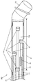
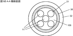
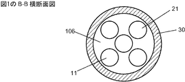
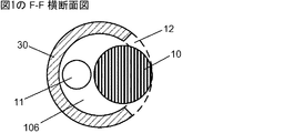
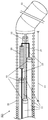
被覆層(30)内に収容され、基端(102)から末端(101)部分まで延びており、かつ、該末端部分を越えた末端が可撓性先端(33/35)を備える、マルチセンサアセンブリ(100/120)であって、
該基端から該末端部分まで延びている、複数の光ファイバ(11)の束、
該末端部分の長さ(41)に沿った複数の位置で圧力を計測するために配設された複数の光学式センサ(10)を備える、該末端部分内のセンサ手段
を備え、
該複数の光ファイバの一つずつが、その末端において該複数の光学式センサの一つずつに光学的に結合されており、かつ該基端(102)において光入出力部(113)に光学的に結合されている、
マルチセンサアセンブリ(100/120);
流体接触のための、各光学式センサに隣接した該被覆層中の開口;
該センサ手段を位置特定するための少なくとも一つのマーカ
を備え、かつ
該被覆層の少なくとも該末端部分が、マイクロカテーテルに通して血管内または腔内に導入するのに適した外径を有する、
流体圧勾配を計測するための装置。
[本発明1002]
前記被覆層が、管腔(106)を画定する内径を有する管状被覆層を含み、前記マルチセンサアセンブリが、該管腔内において前記基端から前記末端部分まで延びている、本発明1001の装置。
[本発明1003]
前記管状被覆層が、マイクロカテーテルおよび操舵可能ガイドワイヤのコイルの一つを含む、本発明1002の装置。
[本発明1004]
前記光学式センサがマイクロオプトメカニカルシステム(Micro-Opto-Mechanical System)(MOMS)圧力センサを備える、本発明1001〜1003のいずれかの装置。
[本発明1005]
前記MOMSセンサがファブリーペロー(Fabry-Perot)MOMSセンサを備える、本発明1004の装置。
[本発明1006]
前記可撓性先端が、心臓弁に通して前記末端部分を導入することを可能にし、かつ前記複数のセンサを備える該末端部分が、心臓の房室にかつ心臓弁に通して導入されるための可撓性を、心臓内の乱流の領域中で該複数のセンサの移動を抑制するための剛性とともに有する、弁内外の圧力勾配を計測するための本発明1001〜1005のいずれかの装置。
[本発明1007]
前記センサ手段が、流量および温度の少なくとも一つを計測するための光学式センサをさらに備える、本発明1001〜1006のいずれかの装置。
[本発明1008]
光学式流量センサが光学式熱対流流量センサを備える、本発明1007の装置。
[本発明1009]
前記センサ手段が電気式流量センサをさらに備え、かつ、前記マルチセンサアセンブリが、該電気式流量センサを前記基端における電気入出力部に結合させる電気接続をさらに備える、本発明1001〜1006のいずれかの装置。
[本発明1010]
前記流量センサが抵抗型/オーム型熱対流流量センサまたはドップラー効果流量センサを備える、本発明1009の装置。
[本発明1011]
前記被覆層の少なくとも前記末端部分が、0.89mmまたはそれ未満の、かつ好ましくは0.46mmまたはそれ未満の外径を有する、本発明1001〜1010のいずれかの装置。
[本発明1012]
前記複数のセンサが、前記末端部分の4cm〜7cmの長さに沿って配設されている、本発明1001〜1011のいずれかの装置。
[本発明1013]
前記マルチセンサアセンブリが、前記基端と前記末端部分の先端の間で1m〜2mの範囲の長さを有し、かつ、光学式圧力センサが、該末端部分の4cm〜7cmの長さに沿って配設されている、本発明1001〜1011のいずれかの装置。
[本発明1014]
前記末端部分の長さに沿って間隔をおいて配設された四つまたはそれ以上の光学式圧力センサを備える、本発明1012または1013の装置。
[本発明1015]
前記被覆層または前記マイクロカテーテルが単層ポリマー管材または多層ポリマー管材を含む、本発明1001〜1014のいずれかの装置。
[本発明1016]
前記ポリマー管材が、ポリイミド、PTFE、または、他の適切な生体適合性もしくは血液適合性の材料を含む、本発明1015の装置。
[本発明1017]
各光学式センサが、前記管腔の内径を越えてかつ前記被覆層の外径を越えずに、前記管状被覆層中の隣接したそれぞれの開口にまで及んでいる、本発明1002の装置。
[本発明1018]
操舵可能ガイドワイヤの形態にあり、前記マルチセンサアセンブリを誘導するためのトルク操舵コンポーネントをさらに備える、本発明1001〜1014のいずれかの装置。
[本発明1019]
前記マルチセンサアセンブリの長さに沿って軸方向に前記末端まで延びているマンドレルと、コイルとを備えるトルク操舵コンポーネントを備える操舵可能ガイドワイヤの形態にあり、前記被覆層が該コイルを含み、かつ該ガイドワイヤが、前記末端部分の長さに沿って0.89mmまたはそれ未満の、かつ好ましくは0.46mmまたはそれ未満の外径を有する、本発明1001〜1014のいずれかの装置。
[本発明1020]
前記可撓性先端がJ字形先端を備える、本発明1015〜1019のいずれかの装置。
[本発明1021]
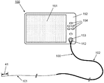
前記マルチセンサアセンブリの前記光入出力部が、該マルチセンサアセンブリを制御システムに光学的に結合させるためのコネクタの一部を構成する、本発明1001〜1020のいずれかの装置。
[本発明1022]
前記コネクタが、電気式センサのための電気接続、および/または該電気式センサと制御システムとのワイヤレス接続性をさらに提供する、本発明1021の装置。
[本発明1023]
センサ配列が、関心対象の弁内外または動脈内の領域の寸法に合致した前記末端部分の長さに沿って配設された複数の少なくとも四つの光学式圧力センサおよび一つの光学式流量センサを備え、かつ、該センサおよび前記光ファイバのそれぞれが、0.89mmまたはそれ未満の、かつ好ましくは0.46mmまたはそれ未満の外径を有するカテーテルまたはガイドワイヤの中に収容されるような外径を有する、弁内外または動脈内の血圧勾配および流速を計測するための本発明1001〜1022のいずれかの装置。
[本発明1024]
前記センサ配列が、関心対象の弁内外または動脈内の領域の寸法に合致した前記末端部分の長さに沿って配設された複数の少なくとも四つの光学式圧力センサおよび一つの電気式流量センサを備え、かつ
該光学式センサ、前記光ファイバ、該電気式センサ、および該電気式センサのための電気接続のそれぞれが、0.89mmまたはそれ未満の、かつ好ましくは0.46mmまたはそれ未満の外径を有するカテーテルまたはガイドワイヤの中に収容されるような外径を有する、
弁内外または動脈内の血圧勾配および流速を計測するための本発明1001〜1022のいずれかの装置。
[本発明1025]
本発明1001〜1024のいずれかの装置を備え、かつ、ユーザインタフェースを備える制御システムをさらに備える、システム。
[本発明1026]
前記光学式センサのそれぞれに結合させるための光源手段および検出手段を備え、かつ電気式センサのための電気接続を備えてもよい、本発明1001〜1024のいずれかの装置を制御するための制御システム。
[本発明1027]
圧力勾配値を示す光学データおよび/または流速値を示す光学データもしくは電気データを処理するためのハードウェアおよび/またはソフトウェア処理手段をさらに備える、本発明1026の制御システム。
[本発明1028]
血管内または弁内外の血圧勾配を計測するためであり、かつ、一つまたは複数の時間間隔および一つまたは複数の心周期中の血圧勾配および/または流速データを図表により表示するためのハードウェアおよび/またはソフトウェア処理手段をさらに備える、本発明1026の制御システム。
[本発明1029]
本発明1001〜1024のいずれかのマルチセンサ装置を提供する工程;
末端部分を、心臓の中にかつモニタされる弁に通して導入しかつ前進させる工程;
該弁の上流側の位置に一つまたは複数の圧力センサが置かれかつ該モニタされる弁の下流側の位置に他のセンサが置かれるように、圧力感知手段を配置する工程;および
該センサを作動させ、かつ各センサから同時にデータを取得して一つまたは複数の時間間隔中の弁内外の血圧勾配を取得する工程
を含む、弁内外の血圧勾配を計測するための方法。
[本発明1030]
本発明1001〜1024のいずれかのマルチセンサ装置を提供する工程;
末端部分を、モニタされる動脈領域または他の血管領域に導入しかつ前進させる工程;
該モニタされる領域の長さに沿った位置に圧力センサが置かれるように、圧力感知手段を配置する工程;および
該センサを作動させ、かつ各センサから同時にデータを取得して一つまたは複数の時間間隔中の血圧勾配を取得する工程
を含む、動脈内または他の血管内の血圧勾配を計測するための方法。
[本発明1031]
前記マルチセンサ装置が、少なくとも一つの流量センサを備え、かつ方法が、
(a)血流速度データを同時に取得する工程;または
(b)一つもしくは複数の心周期にわたって血圧勾配データおよび/もしくは血流量データを収集する工程;または
(c)前記複数の圧力センサおよび/もしくは少なくとも一つの流量センサの選択されたセンサから血圧データ、該血圧勾配データ、および/もしくは該血流量データを収集する工程
の少なくとも一つをさらに含む、本発明1029または本発明1030の血圧勾配を計測するための方法。
[本発明1032]
前記データを図表により表示する工程をさらに含む、本発明1029〜1031のいずれかの血圧勾配を計測するための方法。
例としてのみ示す本発明の態様に関する以下の詳細な説明を添付図面と併せて読むことにより、本発明の前記および他の目的、特徴、局面、および利点がより明らかになろう。
[Invention 1001]
Multi-sensor accommodated in a covering layer (30), extending from a base end (102) to a distal end (101) portion and having a distal end beyond the distal end provided with a flexible tip (33/35) Assembly (100/120),
A bundle of optical fibers (11) extending from the proximal end to the distal portion;
Sensor means in the end portion comprising a plurality of optical sensors (10) arranged for measuring pressure at a plurality of positions along the length (41) of the end portion
With
Each of the plurality of optical fibers is optically coupled to each of the plurality of optical sensors at its distal end, and is optically coupled to the light input / output unit (113) at the proximal end (102). Combined,
Multi-sensor assembly (100/120);
An opening in the coating layer adjacent to each optical sensor for fluid contact;
At least one marker for locating the sensor means
And
At least the end portion of the covering layer has an outer diameter suitable for introduction through a microcatheter into a blood vessel or cavity;
A device for measuring fluid pressure gradients.
[Invention 1002]
The apparatus of claim 1001, wherein the covering layer includes a tubular covering layer having an inner diameter defining a lumen (106), and the multi-sensor assembly extends from the proximal end to the distal portion within the lumen. .
[Invention 1003]
The device of the present invention 1002, wherein the tubular coating layer comprises one of a microcatheter and a steerable guidewire coil.
[Invention 1004]
The apparatus of any of the present invention 1001-1003, wherein the optical sensor comprises a Micro-Opto-Mechanical System (MOMS) pressure sensor.
[Invention 1005]
The apparatus of the present invention 1004, wherein the MOMS sensor comprises a Fabry-Perot MOMS sensor.
[Invention 1006]
The flexible tip allows introduction of the distal portion through a heart valve and the distal portion comprising the plurality of sensors is introduced into the heart chamber and through the heart valve; The device of any of the inventions 1001 to 1005 for measuring pressure gradients inside and outside the valve, with the flexibility of suppressing the movement of the plurality of sensors in the region of turbulence in the heart .
[Invention 1007]
The apparatus according to any one of the inventions 1001 to 1006, wherein the sensor means further comprises an optical sensor for measuring at least one of a flow rate and a temperature.
[Invention 1008]
The apparatus of the present invention 1007, wherein the optical flow sensor comprises an optical thermal convection flow sensor.
[Invention 1009]
Any of the inventions 1001-1006, wherein the sensor means further comprises an electrical flow sensor, and the multi-sensor assembly further comprises an electrical connection coupling the electrical flow sensor to an electrical input / output at the proximal end. Equipment.
[Invention 1010]
The apparatus of the present invention 1009, wherein the flow sensor comprises a resistive / ohmic thermal convection flow sensor or a Doppler effect flow sensor.
[Invention 1011]
The device of any of the present invention 1001-1010, wherein at least the end portion of the covering layer has an outer diameter of 0.89 mm or less, and preferably 0.46 mm or less.
[Invention 1012]
The apparatus of any of the present invention 1001-1011, wherein the plurality of sensors are disposed along a length of 4 cm to 7 cm of the end portion.
[Invention 1013]
The multi-sensor assembly has a length in the range of 1 m to 2 m between the proximal end and the distal end of the distal portion, and an optical pressure sensor is along the length of 4 to 7 cm of the distal portion. The device according to any one of the present inventions 1001 to 1011.
[Invention 1014]
The apparatus of the present invention 1012 or 1013 comprising four or more optical pressure sensors spaced along the length of the distal portion.
[Invention 1015]
The device of any of the present invention 1001-1014, wherein the covering layer or the microcatheter comprises a single layer polymer tube or a multilayer polymer tube.
[Invention 1016]
The device of invention 1015, wherein the polymer tubing comprises polyimide, PTFE, or other suitable biocompatible or blood compatible material.
[Invention 1017]
The device of the invention 1002, wherein each optical sensor extends to an adjacent respective opening in the tubular covering layer beyond the inner diameter of the lumen and without exceeding the outer diameter of the covering layer.
[Invention 1018]
The apparatus of any of the present invention 1001-1014, further in the form of a steerable guidewire, further comprising a torque steering component for guiding the multi-sensor assembly.
[Invention 1019]
In the form of a steerable guidewire comprising a torque steering component comprising a mandrel extending axially along the length of the multi-sensor assembly to the distal end and a coil, the covering layer comprising the coil; and The device of any of the present invention 1001-1014, wherein the guidewire has an outer diameter of 0.89 mm or less and preferably 0.46 mm or less along the length of the distal portion.
[Invention 1020]
The apparatus of any of the inventions 1015-1019, wherein the flexible tip comprises a J-shaped tip.
[Invention 1021]
The apparatus of any of the present invention 1001-1020, wherein the light input / output portion of the multi-sensor assembly forms part of a connector for optically coupling the multi-sensor assembly to a control system.
[Invention 1022]
The apparatus of the present invention 1021, wherein the connector further provides an electrical connection for an electrical sensor and / or wireless connectivity between the electrical sensor and a control system.
[Invention 1023]
The sensor array comprises a plurality of at least four optical pressure sensors and one optical flow sensor disposed along the length of the distal portion that matches the dimensions of the region of the valve inside or outside the valve of interest. And each of the sensor and the optical fiber has an outer diameter such that it is housed in a catheter or guidewire having an outer diameter of 0.89 mm or less, and preferably 0.46 mm or less, The device of any of the present invention 1001-1022 for measuring blood pressure gradients and flow velocities inside or outside a valve or in an artery.
[Invention 1024]
A plurality of at least four optical pressure sensors and one electrical flow sensor disposed along the length of the distal portion that match the dimensions of the region within or outside the valve or artery of interest. Prepared and
Each of the optical sensor, the optical fiber, the electrical sensor, and an electrical connection for the electrical sensor has an outer diameter of 0.89 mm or less, and preferably 0.46 mm or less, or Having an outer diameter to be received in the guide wire,
The device of any of the present invention 1001-1022 for measuring blood pressure gradients and flow velocities inside or outside a valve or in an artery.
[Invention 1025]
A system further comprising a control system including the device according to any one of the present inventions 1001 to 1024 and including a user interface.
[Invention 1026]
Control for controlling the device of any of the inventions 1001-1024 comprising light source means and detection means for coupling to each of said optical sensors and may comprise an electrical connection for an electrical sensor system.
[Invention 1027]
The control system of the present invention 1026 further comprising hardware and / or software processing means for processing optical data indicative of pressure gradient values and / or optical data or electrical data indicative of flow velocity values.
[Invention 1028]
Hardware for measuring blood pressure gradients inside or outside a blood vessel or inside a valve, and for graphically displaying blood pressure gradients and / or flow velocity data during one or more time intervals and one or more cardiac cycles And / or the control system of the present invention 1026, further comprising software processing means.
[Invention 1029]
Providing a multi-sensor device according to any one of the inventions 1001 to 1024;
Introducing and advancing the distal portion into the heart and through the monitored valve;
Positioning pressure sensing means such that one or more pressure sensors are placed at a location upstream of the valve and another sensor is placed at a location downstream of the monitored valve; and
Activating the sensor and obtaining data from each sensor simultaneously to obtain a blood pressure gradient inside and outside the valve during one or more time intervals
A method for measuring a blood pressure gradient inside and outside a valve.
[Invention 1030]
Providing a multi-sensor device according to any one of the inventions 1001 to 1024;
Introducing and advancing the distal portion into the monitored arterial region or other vascular region;
Positioning the pressure sensing means such that the pressure sensor is positioned at a position along the length of the monitored region; and
Activating the sensor and simultaneously obtaining data from each sensor to obtain a blood pressure gradient during one or more time intervals
A method for measuring a blood pressure gradient in an artery or other blood vessel.
[Invention 1031]
The multi-sensor device comprises at least one flow sensor, and the method comprises:
(a) obtaining blood flow velocity data simultaneously; or
(b) collecting blood pressure gradient data and / or blood flow data over one or more cardiac cycles; or
(c) collecting blood pressure data, blood pressure gradient data, and / or blood flow data from selected sensors of the plurality of pressure sensors and / or at least one flow sensor;
The method for measuring a blood pressure gradient of the present invention 1029 or the present invention 1030, further comprising at least one of the following.
[Invention 1032]
The method for measuring a blood pressure gradient of any of the present invention 1029-1031, further comprising the step of displaying the data graphically.
The foregoing and other objects, features, aspects and advantages of the present invention will become more apparent from the following detailed description of embodiments of the invention given by way of example only in conjunction with the accompanying drawings.
図面において、異なる図中の同一の要素または対応する要素は同じ参照番号を有する。
態様の詳細な説明
図1は、血圧、圧力勾配および流速を計測するための、マルチセンサワイヤの形態にある本発明の態様による装置100の、内部構造およびコンポーネントを示す縦断面図を示す。マルチセンサワイヤ100は、以下で詳細に説明する通り、たとえば、最小侵襲処置を使用して、細ゲージ支持カテーテルに通して対象に導入することによる血管内使用に適した長さおよび直径を有する。マルチセンサアセンブリの末端部分101は、先端33近くに、この態様においては、複数の四つの光学式圧力センサ10および一つの光学式流量センサ20の配列を備える圧力および流量感知手段を備える。各センサは、それぞれの個々の光ファイバ11を介して、制御システム(図4を参照)へのマルチセンサワイヤ100の結合のための、基端102における光入出力コネクタ112に結合されている。マルチセンサアセンブリのための被覆またはクラッドを形成する単層または多層管材を含む外層または被覆層30が提供されている。この態様において、層30は、光ファイバ11の束を包囲し、かつ末端における丸みのある先端33まで延びている管腔106を有するマイクロカテーテル(たとえば可撓性ポリマー管材)を含む。先端33は、好都合には、模式的に示す通り、挿入しやすくするために、柔らかく可撓性の先端である。また、マルチセンサワイヤの基端102においても、厚めの保護ジャケットまたはスリーブ32が層30の周囲に提供されている。末端部分には、管材30中、各センサ10に隣接して開口12が設けられている。また、計測中にセンサの位置特定を支援するために、末端部分101の長さに沿ったいくつかの位置に放射線不透過性マーカ14が提供されている。マルチセンサアセンブリの構造はコネクタ112から先端33までのその長さに沿って断面図で示されているが、簡潔に示すために、コネクタ112の内部構造は示されていない。従来どおり、光ファイバ11がコネクタを通過してコネクタの光入出力部113まで延びているということが理解されると考えられる。
Detailed Description of Embodiments FIG. 1 shows a longitudinal section showing the internal structure and components of a
図1に示す通り、マルチセンサワイヤ100は、その基端にハブ103を備えてもよく、このハブが、ポート105を有するサイドアーム104に通じるYコネクタを提供し、ポートが管腔、すなわち空所または空間106へのアクセスを提供する。このようなポートは、従来、管腔を流体でフラッシュまたは充填するために、カテーテルまたはガイドワイヤ中に設けられる。管腔106は、光ファイバ11の周囲を、ポリマー管材30の長さに沿って、マルチセンサワイヤの末端にある、各センサ10の近くの開口12まで延びている。使用中、サイドアーム中のポート105は、管腔106を流体、たとえば生理食塩水でフラッシュおよび充填する能力を提供し、それが、任意の気泡、特に、周囲流体中の圧力計測に干渉し得る、開口12近くのセンサ10の領域に閉じ込められ得る気泡をなくすかまたは除去するのに役立つ。
As shown in FIG. 1, the
図2は、図1に示すマルチセンサワイヤ100の末端部分101の拡大縦断面図を示す。図示する通り、マルチセンサワイヤ100は、マルチセンサワイヤの末端部分の長さ41に沿って配設された四つの光ファイバベースの圧力センサ10を使用して、いくつかの点、この場合は四つの点で同時に血圧を計測することができる。たとえば、図示する通り、センサは、末端部分101のうち、モニタされる心臓または血管領域の寸法によって決まる長さに沿って等間隔に配設される。血流制限の定量化は圧力差および血流速度に関連するため、マルチセンサワイヤ100はまた、好ましくは、血流速度を計測することができるべきである。したがって、それは、血流速度を計測するために、末端部分101の適切な位置に組み込まれた光ファイバ流量センサ20を備える。
FIG. 2 shows an enlarged longitudinal sectional view of the
図3A、3B、3C、3D、3E、3F、および3Gは、マルチセンサワイヤ100をそれぞれ図1のA-A、B-B、C-C、D-D、E-E、F-F、およびG-G面から見た拡大軸方向断面図を示し、ポリマー管材30の管腔106内の光ファイバ11、圧力センサ10および光ファイバ流量センサ20の位置を示す。ポリマー管材30は一般に、ポリイミドもしくはポリテトラフルオロエチレン(PTFE)などのポリマー材料または所望の機械的性質を有する他の適切な生体適合性もしくは血液適合性の材料の一つまたは複数の層を含み、かつ、マルチセンサワイヤを支持カテーテルまたはガイドカテーテルの中に導入しかつその中で容易に滑らせることを可能にする、可撓性管材である。末端における放射線不透過性マーカ14が、術者が、フルオロスコープなどの従来の医学的画像診断システムを使用して、血管領域内または心臓内のマルチセンサワイヤ100のセンサの位置を特定することを可能にする。ポリマー管材30中の開口12は、センサ10および20が、圧力および流量計測のために、周囲流体、たとえば血管内血液に暴露されることを可能にする。
3A, 3B, 3C, 3D, 3E, 3F, and 3G are enlarged axial cross-sectional views of
模式的に示す通り、各センサ10は、それが結合されている光ファイバよりも直径がわずかに大きくてもよい。しかし、各光学式圧力センサ10は、好ましくはMOMS技術に基づくマイクロセンサであり、かつより好ましくは、それらは、二つのミラーの一方がダイアフラムである、ファブリーペロー(Fabry-Perot)光共振器を含む。低コヒーレンス光が光ファイバ11を介して制御装置から入出力コネクタ112を通して空洞共振器に送られる。検出器で受けられる反射光において検出されるスペクトル変化から、圧力変化によるダイアフラムの動きが計測される。そのようなセンサは、たとえば米国特許第7,684,657号および同第7,689,071号に記載されている。
As shown schematically, each
たとえば光ファイバまたは他の可撓性光導波路を介して制御システムに光学的に結合され得るこのタイプの光学式圧力センサは、多湿条件ならびにガイドワイヤ内に組み込まれた電気接続に必要な長い電線に関連する寄生性電磁気干渉およびノイズに対して実質的に影響されない。そのうえ、光学式圧力センサ10は、MEMSセンサと比較して小さな寸法で、たとえば250μmまたはそれ未満の外径で製造することができる。各光学式圧力センサは、MEMSセンサの場合に求められる複数の電線とは違い、結合のために一つの光ファイバしか要らない。光学式センサは、一部のMEMSセンサに関して報告されている電子ドリフトに感応しない。したがって、これらの光学式圧力センサは、0.89mm(0.035インチ)またはそれ未満の外径、および好ましくは末端で0.46mm(0.018インチ)またはそれ未満の外径を有するマルチセンサワイヤ100内への複数の圧力センサ10のアセンブリの組み込みを可能にする。
This type of optical pressure sensor, which can be optically coupled to the control system via, for example, an optical fiber or other flexible optical waveguide, is suitable for humid conditions as well as long wires required for electrical connections built into the guidewire. Substantially insensitive to associated parasitic electromagnetic interference and noise. Moreover, the
図1に示す通り、有利には、先に引用した同時係属中の米国特許仮出願第61/552,787号でより詳細に記載されているタイプの新規な光学式に結合された熱対流流量センサを備える、光学式センサも、流量センサ20は備える。好ましくは、このマイクロ流量センサは、それが結合されている光ファイバ11の直径、すなわち125μmに近い直径を有することが好ましい。または、他の適切なマイクロ流量センサ、たとえばドップラー効果または感温抵抗器のいずれかに基づく流量センサが使用されてもよい。
As shown in FIG. 1, a novel optically coupled thermal convection flow sensor of the type described in more detail in the above-cited copending U.S. Provisional Application No. 61 / 552,787 is advantageously used. The
したがって、例示的な態様において、マルチセンサワイヤ100の外径は、断面B-BおよびC-Cの場合で0.53mm(0.021インチ)であり、断面D-D、E-E、およびF-Fの場合で0.46mm(0.018インチ)である(図2および図3A〜3Fを参照)。すなわち、マルチセンサワイヤは、断面B-Bでは五つすべてのファイバ11および21を収容しなければならないが、一つのファイバおよびセンサしか延びていない断面F-Fに向かってわずかに狭まる。圧力センサ10の計測範囲は一般に-300mmHg〜+300mmHgであり、精度は+/-2mmHgであると考えられる。光ファイバ11および圧力センサ10の外径は、それぞれ0.125mm(0.005インチ)および0.260mm(0.010インチ)であると考えられる。図1に示す通り、圧力センサ10は一般に、マルチセンサワイヤ100の末端の先端33から4〜7cm(1.57〜2.76インチ)の距離41内に位置する。
Thus, in the exemplary embodiment, the outer diameter of the
この態様において、各圧力センサ10は、たとえば接着剤接合または他の適切な接合法により、個々の光ファイバ11に光学的に結合されている。必要ならば、接合領域を保護するためおよび/または機械的補強を提供するために、ある長さの保護管材、たとえばポリイミドが、光学式センサの周囲に、および光ファイバの末端における短い長さ、たとえば数mm提供されてもよい。適切な手動または自動の整合および接着を使用して、個々のファイバの束を整合させて、各センサの間に必要な空間を提供するようにセンサを配設する。管材によって保護される圧力センサ10の全外径は約0.30mm(0.012インチ)であると考えられる。マルチセンサワイヤ100は一般に、柔らかく可撓性のJ字形先端であってもよい丸みのある先端33を提供されるであると考えられる。マルチセンサワイヤ100の先端33からジャケット32の末端までの距離は一般に約1.6m(63インチ)であると考えられる。
In this embodiment, each
図4に示す通り、マルチセンサワイヤシステムはマルチセンサワイヤ装置100およびシステム制御装置150を備える。システム制御装置150は、各位置における圧力センサ10および光ファイバ流量センサ20からの計測データを示すチャートをリアルタイムで同時に表示するためのユーザインタフェースフロントパネル152およびグラフィカルユーザインタフェース151を有する。ユーザインタフェースは、フロントパネル152上の、および/またはタッチスクリーン151の一部としてのコントロール154を備える。マルチセンサワイヤ100は、マルチセンサワイヤ入出力コネクタ112およびユーザインタフェース入出力ポート153を介してシステムユーザインタフェース150に取り付けられる。
As shown in FIG. 4, the multi-sensor wire system includes a
制御システム150は、システムを制御すること、圧力、流量、および任意の他の計測パラメータを示すデータをセンサ10および20から取得すること、およびデータを所望のフォーマットで表示または記憶することのための適したハードウェアおよびソフトウェアとともに、プロセッサを備える。それはまた、それぞれのファイバ11を介して光を各光学式圧力センサ10に送る光源と、圧力値を示す、ファブリーペローセンサから反射した光における変化を検出するための検出システムとを備える。同様に、光は、それぞれのファイバ21を介して流量センサ20に送られ、検出器で受けられた光における変化が、流速に依存する熱変化を示す。必要ならば、制御装置150は、より高強度の別個の光源と、光学式流量センサ20のための検出器とを備えてもよい。他の電気式センサまたは周辺装置が使用される場合には、制御装置は、適切な電気接続および電子部品を備える。制御システム150は、独立ユニットであっても、PCから実行される光学制御ユニットであっても、または心臓病学的処置に使用される他の機器と統合されたシステムの一部であってもよい。
The
以下の部分では、各心臓弁に関する弁内外の圧力勾配および流量を計測およびモニタし、他の血管を評価またはモニタするための方法を詳細に説明する。 In the following sections, a method for measuring and monitoring the pressure gradient and flow rate inside and outside the valve for each heart valve and evaluating or monitoring other blood vessels is described in detail.
しかし、マルチセンサワイヤがガイドワイヤの形態をとっている第二の態様を持ち出すために、マイクロカテーテルの形態の光学マルチセンサワイヤ100の使用をまずごく簡潔に説明する。
However, the use of an optical
要するに、血管内または弁内外の血圧勾配および流量を計測するためのマイクロカテーテルの形態の光学マルチセンサワイヤ100の使用において、心臓病専門医は、まず、光学マルチセンサワイヤを関心対象領域の中に速やかに導入することができるよう、ガイド/支持カテーテルを導入すると考えられる。ガイドカテーテルは他の心臓処置のために所定の位置にすでに置かれている場合もある。そうでなければ、従来どおり、これは、まず、確立された技術を使用してトルクを与えることができる、他の血管内のためまたは心臓処置のための従来のガイドワイヤを導入することを含むと考えられる。そのようなガイドワイヤは一般に、J字形の先端を備え、その先端を関心対象領域、たとえば心臓弁または狭窄領域の近くに配置するために操舵および誘導することを可能にするのに適した可撓性およびトルク特性を有する。その後、支持/ガイドカテーテルをガイドワイヤの上に導入する。次いで、ガイドワイヤを抜き取って、その後、光学マルチセンサワイヤを支持カテーテルに通し、圧力勾配および流量計測の関心対象領域に導入することを可能にする。マルチセンサワイヤまたはマイクロカテーテル上の放射線不透過性マーカが、それが関心対象領域、たとえば血管または心臓の中に配置されている間、マルチセンサワイヤおよびそのセンサの位置のモニタリングを可能にする。
In short, in the use of an optical
ひとたびセンサのアレイが適切に配置され、かつマルチセンサワイヤが制御システムに結合されると、センサをアクティブ化して、たとえば心周期中の一つまたは複数の時間間隔中、またはいくつかの周期にわたって、圧力および/または流速データを各センサから同時に収集する。または、センサがアクティブ化されている間、一つの位置から圧力勾配データを簡単かつ速やかに得たのち、別の計測のためにセンサアレイを異なる位置に移動させて、瞬間的な圧力勾配および心血流量情報を提供しながら関心対象領域を診査してもよい。いくつかの状況においては、関心対象領域、たとえば最大制限の領域を見つけやすくするために、マルチセンサワイヤを配置する前にセンサをアクティブ化することが望ましい場合もある。 Once the array of sensors is properly positioned and the multi-sensor wire is coupled to the control system, the sensor is activated, eg, during one or more time intervals during the cardiac cycle, or over several cycles. Pressure and / or flow rate data is collected from each sensor simultaneously. Alternatively, while the sensor is activated, pressure gradient data can be obtained easily and quickly from one location, and then the sensor array can be moved to a different location for another measurement to produce instantaneous pressure gradients and cardiac blood pressure. The region of interest may be examined while providing flow rate information. In some situations, it may be desirable to activate the sensor prior to placing the multi-sensor wire in order to help locate the region of interest, eg, the maximum restricted region.
ガイド/支持カテーテルが他の処置のために所定の位置にすでに置かれていない場合には、自己誘導性のマルチセンサワイヤを有することが望ましい。 It is desirable to have a self-inductive multi-sensor wire if the guide / support catheter is not already in place for another procedure.
したがって、本発明の第二の態様によるマルチセンサワイヤ120は、図5、6、および7に示され、かつ、マルチセンサワイヤを誘導するための統合されたトルク操舵要素、すなわち、従来のガイドワイヤに使用されているものに類似したマンドレル、コイル、およびJ字形先端を備えるガイドワイヤの形態をとっている。図5を参照すると、図1〜4に示すマルチセンサワイヤ100のコンポーネントに類似するすべてのコンポーネントが同じ参照番号で示されている。
Thus, the
したがって、第二の態様のマルチセンサワイヤ120は、中心ワイヤまたはマンドレル31およびコイル状の外層35を備える、すなわちセンサワイヤ100のポリマー管材30の代わりに、外層が金属合金製の細いワイヤコイル35を提供されているという点で、第一の態様のマルチセンサワイヤとは異なる。保護ジャケット32が基端に提供されている。コイル35は、マンドレル31とともに、マルチセンサワイヤ120の操舵可能特性およびトルク供与可能(torquable)特性を提供して、それを、従来のガイドワイヤと同じやり方で成形して、または撓ませて、血管領域を通り抜けさせることができるようにする。マンドレル、コイルおよびJ字形先端33は、基部シャフトに取り付けられた従来のトルク装置13を使用してマルチセンサワイヤを操舵することを可能にする。
Therefore, the
図6の拡大縦断面図に示す通り、末端121において、マルチセンサワイヤ120は、上記態様のものに類似した四つの光学式圧力センサ10を備える。これは、光学式流量センサの代わりに、感温抵抗器の形態の流量センサ25、すなわち、スワンガンツ(Swann-Ganz)カテーテルに使用されているような抵抗型熱対流センサまたはサーミスタを組み込んでいる。このタイプの電気式流量センサの場合、血流センサ25をマルチセンサワイヤコネクタ112を介してシステムユーザインタフェース150に接続するために、コイル35内に一対の電線23が提供される。図7A、7Bおよび7Cは、コイル35内の光ファイバ11、マンドレル31、電線23および圧力センサ10の位置を示す、マルチセンサワイヤ120をそれぞれA-A、B-B、およびC-C面から見た拡大軸方向断面図である。
As shown in the enlarged longitudinal section of FIG. 6, at the
マルチセンサワイヤ120は、好ましくは、マルチセンサワイヤ100の外径に近い外径、すなわち、末端の近くで0.89mmまたはそれ未満の、かつ好ましくは0.46mmまたはそれ未満の外径を有する。
マルチセンサワイヤ120は操舵可能であるため、はじめにガイドカテーテルを導入する必要なく、マルチセンサワイヤ120は圧力勾配および流量計測のために速やかに導入することができる。ガイドワイヤを前進させながら圧力勾配の計測を実施してもよい。
Since the
別の態様(図示せず)のマルチセンサワイヤ130においては、図1〜4を参照して説明した全光学式センサ態様の代わりに、光学式流量センサ20は、光ファイバ21ではなく一対の電線23によって制御システムの電気コネクタに結合されている、第二の態様において使用されるものに類似した従来の抵抗型熱対流センサ25を備えてもよい。
In another embodiment (not shown) of the
さらに別の態様(図示せず)においては、図5に示すものに類似しているが、光学式流量センサを使用する装置が提供されてもよい。これは、全光学式マルチセンサワイヤ実施態様を提供し、電気接続の必要をなくす。 In yet another embodiment (not shown), an apparatus using an optical flow sensor may be provided that is similar to that shown in FIG. This provides an all-optical multi-sensor wire implementation and eliminates the need for electrical connections.
四つの光学式マイクロ圧力センサおよび一つの光学式流量センサを含むいくつかの態様が実例として記載されかつ示されているが、他の態様は、異なる数およびタイプの圧力および流量センサを提供してもよいことが理解されると考えられる。しかし、圧力差を計測するためには少なくとも二つの圧力センサが必要であり、好ましくは、圧力勾配を計測するためには、四つまたはそれ以上の圧力センサが、たとえば関心対象の心臓弁または血管領域の各側に二つ提供される。マルチセンサワイヤの末端部分に沿ったセンサの間隔は、センサを適切な位置に配置するように選択され得るが、一般に心臓適用の場合、たとえば四つの等間隔のセンサによって約4cm〜7cmの長さに沿って勾配を計測するために配置され得る。流量の同時計測の場合、少なくとも一つの流量センサがさらに必要になる。好都合には、光学式圧力センサは、複数の長い電気接続の必要ならびにそれに伴う信頼性の問題、電磁気ノイズおよび干渉の問題をなくす。放射線不透過性マーカが、適宜、センサ上またはマルチセンサワイヤに沿って間隔をおいて提供されてもよいが、代替的に、他の画像診断方式との使用のために他の適切なマーカが提供されてもよい。必要ならば、装置の管腔を充填またはフラッシュするためのポート、たとえば、他の従来の配設のように図1に示すサイドアームポートを有するハブが設けられる。 While several embodiments including four optical micro pressure sensors and one optical flow sensor have been described and shown by way of example, other embodiments provide different numbers and types of pressure and flow sensors. It is thought that it is good. However, at least two pressure sensors are required to measure the pressure difference, and preferably four or more pressure sensors are used, for example a heart valve or blood vessel of interest, to measure the pressure gradient. Two are provided on each side of the area. The spacing of the sensors along the distal portion of the multi-sensor wire can be selected to place the sensors in the proper location, but generally for cardiac applications, for example, approximately 4 cm to 7 cm long by four equally spaced sensors. Can be arranged to measure the gradient along. In the case of simultaneous flow rate measurement, at least one flow rate sensor is further required. Conveniently, the optical pressure sensor eliminates the need for multiple long electrical connections and the associated reliability problems, electromagnetic noise and interference problems. Radiopaque markers may be provided on the sensor or at intervals along the multi-sensor wire, as appropriate, but alternatively other suitable markers may be used for use with other imaging techniques. May be provided. If necessary, a hub is provided having a port for filling or flushing the lumen of the device, for example a side arm port as shown in FIG. 1 as in other conventional arrangements.
多数のセンサ、たとえば八つまたはそれ以上のセンサを提供することが望ましいこともあるが、数は、マルチセンサワイヤの最大許容直径ならびにセンサおよび光ファイバのサイズによって制限され、また、マルチセンサワイヤに求められる可撓性または剛性などの他の要因に依存し得る。ファブリーペローMOMS圧力センサが記載されているが、代替態様においては、他の適切な小型光学式圧力センサが使用されてもよい。任意で、他のセンサ、たとえば温度センサまたは複合型流量・温度センサが提供されてもよい。 While it may be desirable to provide a large number of sensors, for example eight or more sensors, the number is limited by the maximum allowable diameter of the multi-sensor wire and the size of the sensor and optical fiber, It may depend on other factors such as the required flexibility or stiffness. While a Fabry-Perot MOMS pressure sensor has been described, in an alternative embodiment, other suitable miniature optical pressure sensors may be used. Optionally, other sensors may be provided, such as a temperature sensor or a combined flow and temperature sensor.
マルチセンサワイヤが組み込み流量センサを備えていない場合には、心臓流速は、代替的に、別個のスワンガンツカテーテル、ドップラー超音波エコー診断法、ドップラー効果流量センサまたはフィック法によって従来のやり方で計測されてもよい。 If the multi-sensor wire does not have a built-in flow sensor, the cardiac flow rate is alternatively measured in a conventional manner by a separate Swan Gantz catheter, Doppler ultrasound echo diagnostic method, Doppler effect flow sensor or Fick method. Also good.
五つの光ファイバ11のそれぞれに関する入出力のための単一の光学コネクタ112が示されているが、他の態様においては、代替のコネクタまたは結合配列が提供されてもよい。マルチセンサワイヤコネクタ112およびユーザインタフェースポート153は、一つのマルチファイバコネクタの代わりにいくつかの個々の光ファイバコネクタを備えてもよい。さらに他の態様においては、複数のセンサ10および20が、マルチセンサワイヤに沿ったどこかの地点にあるマルチポート光カプラを介して一つのファイバに結合されて、複数のセンサからの信号が多重化されてもよい。コネクタ112は任意で、マルチセンサワイヤ100とシステム制御装置150およびユーザインタフェース151の間の制御およびデータ信号のワイヤレス通信を可能にする回路を備えてもよい。任意で、周辺装置のためのまたはさらなるもしくは代替の電気式センサのための一つまたは複数の電気コネクタが提供されてもよい。
Although a single
また、医学的適用または獣医学的適用の場合、マルチセンサワイヤは、適切な生体適合性材料から製造され、かつ適切な無菌パッケージ形態で提供されるべきであることが理解されると考えられる。一般に、マルチセンサワイヤアセンブリは使い捨て用に提供され、ディスポーサブルである。したがって、適したコンポーネントおよび材料を選択する際には、コストおよび環境的考慮が重要になり得る。 It will also be appreciated that for medical or veterinary applications, the multi-sensor wire should be manufactured from a suitable biocompatible material and provided in a suitable sterile package form. In general, multi-sensor wire assemblies are provided for disposable use and are disposable. Thus, cost and environmental considerations can be important when selecting suitable components and materials.
心臓の大動脈弁、僧帽弁、三尖弁、および肺動脈弁をはさんだ弁内外の圧力勾配の計測
図1〜4を参照して説明したような態様によるマルチセンサワイヤ100を使用して、ヒト心臓200における大動脈弁211をはさんだ血圧勾配、すなわち大動脈弁内外の圧力勾配を計測およびモニタするための本発明の第一の態様による方法を、以下、図8を参照しながら説明する。まず、公知の技術を使用して、従来のガイドワイヤを末梢動脈、たとえば大腿動脈または頚動脈に挿入し、上行動脈210に通して前進させる。次いで、支持カテーテル160をガイドワイヤの上に滑らせる。次いで、術者は、支持カテーテル160を前進させ、その末端の可視化装置、たとえば放射線不透過性マーカを使用しながら大動脈弁211の近くに配置する。次いで、術者は、支持カテーテル160の管腔中でガイドワイヤをマルチセンサワイヤ100に換える。術者は、マルチセンサワイヤ100の末端を前進させ、その末端の可視化装置、たとえば放射線不透過性マーカ14を使用しながら左心室212の中に配置する。マルチセンサワイヤ100がひとたび正しく配置されると、システムが大動脈弁211の弁内外の圧力勾配を計測する。図8に模式的に示す通り、三つの圧力センサ10が左心室212中に配置され、一つの圧力センサが、大動脈弁211のすぐ下流の大動脈160中に配置されて、弁の上流側および下流側の四つの位置で圧力の同時計測を可能にする。いくつかの心周期中に一連の計測を実施してもよい。図8には示されていないが、流量の同時計測のために流量センサ20が提供されてもよい。計測結果は、図表により、たとえば、圧力勾配および流量を示すシステム制御装置150(図4を参照)のグラフィカルユーザインタフェース151上のチャートとして表示されてもよい。制御システムは、いくつかの周期で平均化される複数の計測を提供してもよく、かつ/または可視化される周期間の変動を提供してもよい。適切ならば、マルチセンサワイヤは、代替的に、たとえば、大動脈弁213の上流側および下流側それぞれに二つ配置された圧力センサによって四つの異なる位置で同時に計測を実施するように配置されてもよい。したがって、術者は、弁内外圧力勾配計測を速やかにかつ容易に得ることができる。計測は、たとえば、弁置換処置または弁修復処置の前後に実施され得る。
Measurement of pressure gradient inside and outside the heart aortic valve, mitral valve, tricuspid valve, and pulmonary valve using a
ヒト心臓200における僧帽弁213をはさんだ血圧勾配、すなわち僧帽弁内外の圧力勾配を計測およびモニタするための第二の態様による方法を以下に記載し、図9によって説明する。まず、公知の技術を使用して、ガイドワイヤを末梢大静脈、たとえば下大静脈220に挿入し、上行静脈220に通して右心房221まで前進させる。次いで、支持カテーテル160をガイドワイヤの上に滑らせる。次いで、術者は、公知の技術を使用して、支持カテーテル160を右心房221まで前進させ、さらに中隔を越えさせて、左心房214中、僧帽弁213の近くに支持カテーテル160を配置する。次いで、術者は、支持カテーテル160の管腔中でガイドワイヤをマルチセンサワイヤ100に換える。術者は、マルチセンサワイヤ100の末端を前進させ、その末端の可視化装置、たとえば放射線不透過性マーカ14を使用しながら左心室212の中に配置する。ひとたびマルチセンサワイヤ100が正しく配置されると、システムが僧帽弁213の弁内外の圧力勾配を計測および表示する。
A method according to the second embodiment for measuring and monitoring the blood pressure gradient across the
ヒト心臓200における三尖弁222をはさんだ血圧勾配、すなわち三尖弁内外の圧力勾配を計測およびモニタするための第三の態様による方法を以下に記載し、図10によって説明する。まず、公知の技術を使用して、ガイドワイヤを末梢大静脈、たとえば下大静脈220に挿入し、上行静脈220に通して右心房221まで前進させる。次いで、支持カテーテル160をガイドワイヤの上に滑らせる。次いで、術者は、支持カテーテル160を前進させ、その末端の可視化装置、たとえば放射線不透過性マーカを使用しながら三尖弁222の近くに配置する。次いで、術者は、支持カテーテル160の管腔中でガイドワイヤをマルチセンサワイヤ100に換える。術者は、マルチセンサワイヤ100の末端を前進させ、その末端の可視化装置、たとえば放射線不透過性マーカ14を使用しながら右心室223の中に配置する。ひとたびマルチセンサワイヤ100が正しく配置されると、システムが三尖弁222の弁内外の圧力勾配を計測および表示する。
A method according to the third aspect for measuring and monitoring the blood pressure gradient across the
同様に、第四の態様において、ヒト心臓200における肺動脈弁224をはさんだ血圧勾配(すなわち肺動脈弁内外圧力勾配)を計測およびモニタするための方法を以下に記載し、図11によって説明する。術者が、マルチセンサワイヤ100の末端を前進させ、上記の通りにその末端の可視化装置、たとえば放射線不透過性マーカ14を使用しながら右心室223の中に配置する。次いで、術者はさらに、支持カテーテル160を肺動脈弁224の近くまで前進させる。次いで、術者はさらに、マルチセンサワイヤ100の末端を前進させ、肺動脈225の中に配置する。ひとたびマルチセンサワイヤ100が正しく配置されると、システムが肺動脈弁224の弁内外の圧力勾配を計測および表示する。
Similarly, in the fourth embodiment, a method for measuring and monitoring the blood pressure gradient across the pulmonary valve 224 (ie, the pressure gradient inside and outside the pulmonary valve) in the
心臓の機能は、脱酸素化された血液を静脈から肺に送り、かつ酸素化された血液を肺から動脈を介して体に送ることである。心臓の右側が、脱酸素化された血液を大きな末梢静脈、たとえば下大静脈220から右心房221の中に集める。血液は、右心房221から三尖弁222を通過して右心室223に入る。右心室223は、脱酸素化された血液を肺動脈225を介して肺に送り込む。その間、心臓の左側は、酸素化された血液を肺から左心房214の中に集める。血液は、左心房214から二尖弁213を通過して左心室212に入る。その後、左心室212が酸素化された血液を大動脈210に通して体じゅうに送り出す。
The function of the heart is to send deoxygenated blood from the veins to the lungs and oxygenated blood from the lungs through the arteries to the body. The right side of the heart collects deoxygenated blood from a large peripheral vein, such as the
心周期を通して、血圧は、たとえば、健康な心臓に典型的な曲線を示す図12の圧力曲線330および340によってそれぞれ示される通り、大動脈基部210および左心室212の中で上昇および減少する。心周期は、特殊な心臓細胞によって生成される一連の電気インパルス310によって協調される。心室収縮期301とは、右心室223および左心室212の筋肉(心筋)がほぼ同時に収縮して血液を循環系に送り込み、心室内の血液量320を急激に減らす期間である。心室拡張期302とは、心室320が、収縮後、循環血の再充填に備えて弛緩する期間である。心室拡張期302中、左心室中の圧力340は最低値まで低下し、心室内の血液量320が増す。
Throughout the cardiac cycle, blood pressure rises and decreases in the
図13および14は、健康な心臓ならびに狭窄231、232、および233を有する心臓に関して上記の第一の態様の方法を使用してマルチセンサワイヤ100によって計測される大動脈弁内外圧力勾配の概念を示す、大動脈弁211および左心室212の簡略図である。この特定の例において、大動脈弁内外圧力勾配は、左心室212および大動脈基部210内の位置P1、P2、P3、およびP4でセンサによって計測された血圧である。
FIGS. 13 and 14 illustrate the concept of an aortic valve internal and external pressure gradient measured by
図13に示す、病変のない左心臓は、図12の曲線330および340にそれぞれ類似した大動脈および心室圧曲線を生成すると考えられる。しかし、図14に示す心臓は、複数の潜在的血流230閉塞部位231、232、および233を有する。いくつかの場合、マルチセンサワイヤ100の術者は、大動脈弁上狭窄231(最も一般的には、大動脈基部中に位置する異常な先天性の膜)を評価するために、大動脈基部210内のいくつかの位置P4およびP3で血圧を計測することを望む場合もある。
The left lesion-free left heart shown in FIG. 13 is thought to produce aortic and ventricular pressure curves similar to
患者の心臓から収集された心臓血行動態データは、臨床医が狭窄病変の生理学的有意性を評価することを可能にする。患者心臓からの大動脈および心室圧曲線を予測圧力曲線と比較する。図15は、心臓内閉塞による大動脈圧曲線330と心室圧曲線340の間の典型的な差を示す。これらの変動のいくつかは、曲線330と340の間の最大差305およびピーク間の差306を含む。また、大動脈圧曲線330と心室圧曲線340の間の区域307が、狭窄病変の生理学的有意性を評価するために使用される。大動脈圧曲線330の振幅303と心室圧曲線340の振幅304の間の差もまた、臨床医にとって重要な情報である。
Cardiac hemodynamic data collected from the patient's heart allows clinicians to assess the physiological significance of stenotic lesions. The aorta and ventricular pressure curves from the patient heart are compared to the predicted pressure curve. FIG. 15 shows a typical difference between the
心臓カテーテル処置および血行動態に関する医学参照文献が、正しい医学的診断を特定するために、大動脈圧曲線330および心室圧曲線340の様々な可能な変動をその考え得る原因とともに提供している。たとえば、図15に示すような心臓血行動態曲線は、その曲線の分析とともに、Donald S. BaimおよびWilliam Grossmanによる、Grossman's cardiac catheterization, angiography, and interventionと題する参照文献の647〜653頁に記載されている。
Medical references on cardiac catheterization and hemodynamics provide various possible variations of the
図1に模式的に示す通りの、第一の態様に基づくプロトタイプマルチセンサワイヤ100を組み立てかつ試験した。それぞれが個々の光ファイバ11に結合されている四つのFiso FOP-M260圧力センサ10を備えるマルチセンサアセンブリを製造し、そのマルチセンサアセンブリを各センサ10の近くに開口12を有する外径0.76mm(0.028インチ)の三層ポリマー管材の中に囲い込んだ。各センサは0.260mmの外径(OD)を有する。各センサを個々のOD 0.125mm光ファイバに結合した。四つのセンサおよびそれぞれの光ファイバを、マルチセンサワイヤの末端の、先端に近い長さに沿って圧力センサ間に2cmの間隔が提供されるように組み立てた。初期インビトロ実験室試験中、プロトタイプは、静水柱中、正確なリアルタイム圧力勾配計測を提供することを実証した。-300mmHg〜300mmHgの圧力範囲を±2mmHgの精度で計測するようにセンサを較正した。
A
その後、四つの圧力センサを備えるプロトタイプマルチセンサワイヤを、ヒト心臓系の左心室および大動脈中に見られる心臓脈圧および流量を模倣する心臓モデルである簡単なアクティブ化脈拍複製システム(Vivitro Systems)の中で試験した。複製システムは、三葉心膜種である生体弁(Carpentier-EdwardsのPerimount 2900)を備えたものであった。二つの異なる直径の弁、すなわち、正常で健康な弁を模倣する直径29mmの弁および大動脈弁面積が減少した弁を模倣する直径19mmの弁を試験に使用した。一つの圧力センサP1が心室腔内に位置し、別の圧力センサP4が大動脈腔内に位置するようにマルチセンサワイヤを弁開口に挿入した。図16Aおよび16Bは、それぞれ29mm弁および19mm弁の場合の圧力センサP4(大動脈)330およびP1(心室)340からの圧力示度を表す曲線330、340を示す。当業者は、収縮期中、直径19mmの弁の場合、それぞれ心室および大動脈に関する圧力P1とP4の間の圧力差が直径29mmの弁の場合の差よりも大きく、弁面積の減少を示すことを認めると考えられる。
Later, a prototype multi-sensor wire with four pressure sensors was developed for the simple activated pulse replication system (Vivitro Systems), a heart model that mimics the heart pressure and flow found in the left ventricle and aorta of the human heart system. Tested in. The replication system was equipped with a biological valve, a trilobal pericardial species (Carpentier-Edwards Perimount 2900). Two different diameter valves were used in the test: a 29 mm diameter valve that mimics a normal healthy valve and a 19 mm diameter valve that mimics a valve with reduced aortic valve area. A multi-sensor wire was inserted into the valve opening so that one pressure sensor P1 was located in the ventricular cavity and another pressure sensor P4 was located in the aortic cavity. FIGS. 16A and 16B show
図12および15に示す模範的血行動態曲線と図16Aおよび16Bに示す実験的に計測した曲線との比較のために、対応する圧力トレースを同じ参照番号で標識した。すなわち、各図は大動脈圧トレース330および心室圧トレース340を示す。図16Aおよび16Bに示す各プロット中、第三の曲線345は、P1(心室)から2cmのところに位置する別のセンサP2の圧力曲線を表す。他のセンサP3の曲線は図示されていない。
For comparison of the exemplary hemodynamic curves shown in FIGS. 12 and 15 with the experimentally measured curves shown in FIGS. 16A and 16B, the corresponding pressure traces were labeled with the same reference numbers. That is, each figure shows an
図16Cは、同じ実験からデータの別のプロットを示す。この図は、異なる直径の二つの弁のそれぞれに関して、それぞれ心室中および大動脈中に位置する二つの圧力センサによって計測された、圧力差P1(心室)−P4(大動脈)を示す。図16Cに示す圧力差計測は、直径29mm弁(曲線360)の場合に対して直径19mm弁(曲線350)の場合のはるかに大きなピーク弁内外圧力差によって証明される性能の低下を強調する。 FIG. 16C shows another plot of data from the same experiment. This figure shows the pressure difference P1 (ventricle) -P4 (aorta), measured by two pressure sensors located in the ventricle and the aorta, respectively, for each of the two valves of different diameters. The pressure difference measurement shown in FIG. 16C highlights the performance degradation evidenced by the much larger peak valve internal and external pressure differentials for the 19 mm diameter valve (curve 350) versus the 29 mm diameter valve (curve 360).
これらの予備的結果から、複数の光学式圧力センサを備えるマルチセンサワイヤが、インビボ血圧勾配の計測ならびに大動脈および心室圧曲線のデータの取得のために、適した圧力範囲において適切な感度、精度、および分解能で圧力勾配の光学計測を提供するということが明らかである。これらの初期結果は、インビボ試験および前臨床試験の前に、心臓モデルにおいて生体心臓弁の動作を評価するための大動脈および心室圧曲線の計測にマルチセンサワイヤが効果的であることを実証する。 From these preliminary results, a multi-sensor wire with multiple optical pressure sensors has the appropriate sensitivity, accuracy, and accuracy in the appropriate pressure range for in vivo blood pressure gradient measurement and aortic and ventricular pressure curve data acquisition. Obviously, it provides an optical measurement of pressure gradient with resolution. These initial results demonstrate that multi-sensor wires are effective in measuring aortic and ventricular pressure curves to assess the behavior of living heart valves in heart models prior to in vivo and preclinical studies.
要するに、四つの心臓弁のそれぞれの弁内外の圧力勾配の計測の簡素化のための本発明の態様による装置、システム、および方法が記載される。特に、複数の小型センサを使用することにより、複数の、たとえば四つのマイクロ圧力センサを備える直径0.89mm(0.035インチ)またはそれ未満のマイクロカテーテルを通す間に機能不全弁の一部分または他の部分の圧力を同時に計測することが可能である。一つまたはいくつかのセンサは弁の一方または他方の側に位置しており、その結果、たとえば最大閉塞の領域における瞬間的な計測を可能にすることができる。装置の小さな物理的サイズは、弁を通過する場合、または弁に挿入される場合、弁動作への干渉を減らし、たとえば、弁の動きへの干渉の減少および/または弁内外の圧力勾配の乱れの減少を提供する。そのうえ、狭窄が厳密に弁と関連しているかどうか、弁下狭窄(たとえば大動脈弁下肥大性狭窄)または弁上狭窄に関連しているかの決定を可能にする計測を可能にする。たとえば、大動脈弁狭窄の重篤度は、従来から、>50mmHgの平均圧力勾配または<0.75cm2の弁面積によって決定される。 In summary, an apparatus, system, and method according to aspects of the present invention for simplifying the measurement of pressure gradients inside and outside each of four heart valves is described. In particular, by using multiple miniature sensors, one or other parts of the dysfunctional valve can be passed through a plurality of microcatheters with a diameter of 0.89 mm (0.035 inches) or less, for example with four micro pressure sensors. It is possible to measure pressure simultaneously. One or several sensors may be located on one or the other side of the valve, so that instantaneous measurements can be made, for example in the region of maximum occlusion. The small physical size of the device reduces interference with valve operation when passing through or inserted into the valve, for example, reducing interference with valve movement and / or turbulence of pressure gradients inside and outside the valve. Provide a reduction in Moreover, it allows measurements that allow the determination of whether stenosis is strictly associated with the valve, whether it is associated with subvalvular stenosis (eg, aortic hypertrophic stenosis) or supravalvular stenosis. For example, the severity of aortic stenosis is conventionally determined by an average pressure gradient of> 50 mmHg or a valve area of <0.75 cm 2 .
特に、センサ手段は、たとえば動脈の管腔または心臓の部屋に挿入可能であるガイドワイヤの末端領域または末端に複数の圧力センサまたはセンサのアレイを備え得る。有利には、圧力センサ手段は、カテーテルに通してガイドワイヤとともに体に導入し得る小ゲージ光ファイバに結合された光学式センサを備える。したがって、他のタイプの電気式センサが含まれない限り、圧力を示す信号は、光学的に検出され得、かつ、ガイドワイヤに沿って電気接続を設ける必要をなくし得る。任意で、装置はさらに、温度感知手段または異なるタイプの他のセンサを備えてもよい。たとえば、関連パラメータの計測、たとえば、たとえば抵抗型感知手段によって計測される温度計測および/または流量計測を可能にするために一つまたは複数の電気式センサが含まれてもよい。 In particular, the sensor means may comprise a plurality of pressure sensors or an array of sensors in the distal region or the distal end of a guidewire that can be inserted into an arterial lumen or heart chamber, for example. Advantageously, the pressure sensor means comprises an optical sensor coupled to a small gauge optical fiber that can be introduced into the body with a guide wire through the catheter. Thus, unless other types of electrical sensors are included, a signal indicative of pressure can be detected optically and can eliminate the need to provide an electrical connection along the guidewire. Optionally, the device may further comprise temperature sensing means or other sensors of different types. For example, one or more electrical sensors may be included to allow measurement of relevant parameters, for example, temperature measurement and / or flow measurement measured by, for example, resistive sensing means.
圧力勾配計測の場合、理想的には、データは、複数の圧力センサのそれぞれから同時に、かつ任意で、他のセンサ、たとえば流量センサから同時に集められることが理解されると考えられる。しかし、システムはまた、必要に応じて、データが、一つまたは複数の圧力センサ、流量センサ、温度センサ、または適宜他のセンサから選択的に収集および/または表示され、かつ一つまたは複数の心周期または他の時間間隔で図表により表示されることが可能となるように構成されてもよいことが理解されると考えられる。 In the case of pressure gradient measurements, it will be understood that data is ideally collected simultaneously from each of a plurality of pressure sensors, and optionally from other sensors, such as flow sensors. However, the system can also optionally collect and / or display data selectively from one or more pressure sensors, flow sensors, temperature sensors, or other sensors as appropriate, and It will be understood that it may be configured to be displayed graphically at a cardiac cycle or other time interval.
したがって、本発明の態様による装置は、関心対象領域中のいくつかの点で圧力の同時計測を可能にする装置を医学専門家に提供する。複数の圧力センサが圧力勾配の計測をリアルタイムで提供する。たとえば、複数の圧力センサを備えたそのようなマルチセンサワイヤまたはガイドワイヤは、心臓弁の上流側と下流側の間の圧力差を評価することもできる。計測された圧力差に基づいて心臓弁の劣化を評価することもできる。いくつかの位置における圧力の同時計測が単一点計測よりも有利である他の例がいくつかある。たとえば、そのような装置は、たとえば、心臓動脈閉塞、尿路閉塞、心臓壁の肥厚(心室肥厚)を評価することもできる。有利には、マルチセンサワイヤは、心拍出量および弁面積を同時に、かつ既存の装置および技術と比べてより簡単かつ安全に測定することを可能にする計測を実施することを可能にする。 Thus, an apparatus according to aspects of the present invention provides a medical professional with an apparatus that allows simultaneous measurement of pressure at several points in a region of interest. Multiple pressure sensors provide pressure gradient measurements in real time. For example, such a multi-sensor wire or guide wire with multiple pressure sensors can also assess the pressure difference between the upstream and downstream sides of the heart valve. It is also possible to evaluate the deterioration of the heart valve based on the measured pressure difference. There are several other examples where simultaneous measurement of pressure at several locations is advantageous over single point measurement. For example, such a device can also assess, for example, cardiac artery occlusion, urinary tract obstruction, heart wall thickening (ventricular thickening). Advantageously, the multi-sensor wire makes it possible to perform measurements that make it possible to measure cardiac output and valve area simultaneously and more easily and safely compared to existing devices and technologies.
マルチセンサワイヤの長さおよび直径は、圧力、流量、または温度が計測される適用に依存して選択され得る。たとえば、心臓血管適用、たとえば弁内外計測の場合、センサは、計測が実施される心臓または領域のサイズに依存して、たとえばセンサワイヤの末端部分の一般的に4cm〜7cmの長さに沿って等間隔に配設され得る。計測が実施される領域の寸法に依存して、センサの他の配設が望まれる場合もある。 The length and diameter of the multi-sensor wire can be selected depending on the application in which the pressure, flow rate, or temperature is measured. For example, for cardiovascular applications, such as in-valve measurements, the sensor may be, for example, along a length of typically 4 cm to 7 cm of the distal portion of the sensor wire, depending on the size of the heart or region in which the measurement is performed. It can be arranged at equal intervals. Depending on the dimensions of the area where the measurement is performed, other arrangements of the sensor may be desired.
上記態様において、マルチセンサアセンブリ中の複数の光学式圧力センサは、末端部分に沿った位置に配列されて、末端部分の長さに沿ったそれらの間隔によって、それらの相対位置がわかる、すなわち決定されるようになっている。末端部分は血管内に導入するのに十分に可撓性であるが、複数のセンサどうしの相対動は制限される。したがって、センサから同時にデータを収集する場合、単一センサガイドワイヤを使用して異なる位置で順次に計測する場合に比べ、関心対象領域中の各センサの相対位置がより確かになる。これは、より高い流量および乱流が、センサワイヤの端部に位置する単一センサの過度な動きを生じさせる傾向にある心臓に関して圧力および流量を計測する場合に特に有用である。上記態様は弁内外の血圧勾配および流量の計測およびモニタリングに焦点を置いたものであるが、マルチセンサワイヤ装置および方法は、血管中の圧力勾配および流量を計測するように適合または変形され得ることが理解されると考えられる。マルチセンサワイヤが他の適用に使用される場合、その外径が0.36mm(0.014インチ)またはそれ未満に縮小されなければならない場合もある。センサの配設、たとえばそれらの数、位置および間隔ならびに圧力センサの精度および圧力計測範囲もまた、医学的適用の具体的要件を満たすように調整されなければならない場合もある。 In the above aspect, the plurality of optical pressure sensors in the multi-sensor assembly are arranged at a position along the end portion, and their relative position is known, i.e., determined by their spacing along the length of the end portion. It has come to be. The distal portion is sufficiently flexible to be introduced into the blood vessel, but the relative movement between the sensors is limited. Thus, when collecting data from sensors simultaneously, the relative position of each sensor in the region of interest is more reliable than when sequentially measuring at different positions using a single sensor guidewire. This is particularly useful when measuring pressure and flow with respect to the heart where higher flow and turbulence tend to cause excessive movement of a single sensor located at the end of the sensor wire. While the above aspects focus on measuring and monitoring blood pressure gradients and flows inside and outside the valve, multi-sensor wire devices and methods can be adapted or modified to measure pressure gradients and flows in blood vessels. Is considered to be understood. If the multi-sensor wire is used for other applications, its outer diameter may need to be reduced to 0.36 mm (0.014 inches) or less. The arrangement of sensors, such as their number, position and spacing, and the accuracy and pressure measurement range of the pressure sensor may also have to be adjusted to meet the specific requirements of the medical application.
たとえば、マイクロカテーテルに通して、または複数のセンサを備えた操舵可能ガイドワイヤとして血管に導入し得るマルチセンサワイヤ100の形態の複数の光学式圧力センサ10を備える装置を提供し得る。そのような装置は、図17に模式的に示す通りに、ガイドワイヤの末端部分の長さに沿ったいくつかの位置で同時に圧力を計測するように構成され得る。図17は、血流430に対する制限である複数の狭窄431を有する血管、たとえば動脈401の簡略図を示す。血圧は、マルチセンサワイヤ100によって血管内の四つの異なる位置P1、P2、P3およびP4で同時に計測される。
For example, an apparatus may be provided that includes a plurality of
また、マルチセンサワイヤシステム、装置および方法はまた、体の他の系における、たとえば動物またはヒト対象の尿路、胆管、または静脈系における流体圧、勾配、および流量を計測するために適用され得ることが理解されると考えられる。 In addition, multi-sensor wire systems, devices and methods can also be applied to measure fluid pressure, gradients, and flow rates in other systems of the body, such as in the urinary tract, bile duct, or venous system of an animal or human subject. It is thought that it is understood.
いくつかの態様においては、圧力および流量の両方を計測するための全光学式マイクロセンサを使用して電気接続の必要を全くなくし、それが、電磁気ノイズおよび干渉ならびに信号信頼性の問題を減らす。他の態様においては、光学式圧力センサと、たとえば流量または温度のための一つまたは複数の電気式センサとを組み合わせてもよい。 In some embodiments, all-optical microsensors for measuring both pressure and flow are used to eliminate the need for electrical connections, which reduces electromagnetic noise and interference and signal reliability issues. In other embodiments, an optical pressure sensor may be combined with one or more electrical sensors, for example for flow rate or temperature.
本明細書に関連して、「マルチセンサワイヤ」または「マルチセンサガイドワイヤ」における語「ワイヤ」は、心臓カテーテル処置に使用されるような従来の単一センサワイヤおよびガイドワイヤに類似した小さな直径および細長い形状を有する装置をいうものと解釈されることが理解されると考えられる。すなわち、語「ワイヤ」は、従来の金属ワイヤに限定されるとは解釈されず、マルチセンサ装置の形態を好都合に説明するために、より広い意味で、フィラメント、ストランド、ケーブルまたは他の長細い(すなわち小径の)要素の形態の要素を包含する。上記の通り、いくつかの態様において、マルチセンサワイヤは、電気的コンポーネントなしで、光ファイバなどの可撓性光導波路によって装置の基端における光入出力部に光学的に結合されている複数の光学式圧力センサのアセンブリを備える。これらのコンポーネントは従来の操舵可能ガイドワイヤコンポーネントと一体化されてもよい。いくつかの態様において、従来の有線電気接続を有する(すなわち、従来の導電性金属線を使用する)電気式センサが含まれてもよい。いくつかの態様において、センサ装置は、代替的に、たとえばマルチセンサ装置、マルチセンサ診断ワイヤまたはマルチセンサガイドワイヤと呼ばれてもよい。 In the context of this specification, the term “wire” in “multi-sensor wire” or “multi-sensor guide wire” refers to a small diameter similar to conventional single sensor wires and guide wires as used in cardiac catheterization procedures. And is understood to refer to a device having an elongated shape. That is, the term “wire” is not to be construed as limited to conventional metal wires, but in a broader sense, filaments, strands, cables, or other long and narrow to conveniently describe the form of the multi-sensor device. Includes elements in the form of elements (ie, small diameter). As described above, in some embodiments, the multi-sensor wire is a plurality of optically coupled to the light input / output at the proximal end of the device by a flexible optical waveguide, such as an optical fiber, without electrical components. An optical pressure sensor assembly is provided. These components may be integrated with conventional steerable guidewire components. In some aspects, an electrical sensor having a conventional wired electrical connection (ie, using a conventional conductive metal wire) may be included. In some aspects, the sensor device may alternatively be referred to as, for example, a multi-sensor device, a multi-sensor diagnostic wire or a multi-sensor guide wire.
産業上の適用可能性
本発明の態様にしたがって、圧力勾配もしくは圧力差および/または流量、特に弁内外の圧力勾配の計測を簡素化するシステム、装置、および方法が提供される。そのような計測は、改善された最小侵襲処置を使用して重要な心臓パラメータを測定することを可能にする。心臓病専門医は、たとえば弁修復処置または弁置換処置の前後で弁内外の圧力勾配をより速やかに、簡単に、かつ確実に計測およびモニタするためのツールを提供される。
Industrial Applicability In accordance with aspects of the present invention, systems, apparatus and methods are provided that simplify the measurement of pressure gradients or pressure differentials and / or flow rates, particularly pressure gradients inside and outside a valve. Such a measurement makes it possible to measure important cardiac parameters using an improved minimally invasive procedure. Cardiologists are provided with tools to more quickly, easily and reliably measure and monitor pressure gradients inside and outside the valve, for example before and after valve repair or valve replacement procedures.
システムおよび装置はまた、人工心臓、人工器官心臓弁、および他の医学的使用のための人工的装置の動作の研究、試験、および評価のために圧力勾配の計測を提供することが明らかである。 It is clear that the systems and devices also provide pressure gradient measurements for the study, testing, and evaluation of the operation of artificial devices for artificial hearts, prosthetic heart valves, and other medical uses .
特に、たとえば四つの圧力センサおよび一つの流量センサを備える直径0.89mm(0.035インチ)またはそれ未満のマルチセンサ装置を使用して、心臓病専門医は、マルチセンサ装置のセンサが弁に通して配置されている間、機能不全弁の一つの側から他方の側までのいくつかの点で同時に圧力を計測することが可能である。たとえば、大動脈の直径が既知である場合には、圧力勾配および流量を同時に計測することができるマルチセンサワイヤの使用は、心拍出量の評価および、結果として、たとえば弁面積または管腔面積の推定を可能にする。 In particular, using a multi-sensor device with a diameter of 0.89 mm (0.035 inches) or less, for example with four pressure sensors and one flow sensor, a cardiologist will place the sensor of the multi-sensor device through the valve While running, it is possible to measure the pressure at several points simultaneously from one side of the malfunctioning valve to the other. For example, if the diameter of the aorta is known, the use of multi-sensor wires that can simultaneously measure pressure gradients and flow rates can be used to assess cardiac output and, as a result, for example, valve area or lumen area. Enable estimation.
一つまたは複数のセンサを弁の各側に限局化して、たとえば最大閉塞の領域における圧力勾配および流量の瞬間的な計測を可能にすることができる。たとえば直径0.46mm(0.018インチ)またはそれ未満の末端部分を有するマルチセンサ装置の小型化は、弁を通過する装置の存在が、弁の動きに対して最小限または無視しうる程度の影響しか及ぼさず、かつ弁内外の圧力勾配の計測に対して最小限または無視しうる程度の波及効果しか及ぼさないことを意味する。たとえば、それは、心臓病専門医が、狭窄が厳密に弁と関連しているかどうか、または弁下閉塞、たとえば大動脈弁下肥厚性狭窄に関連しているのかの速やかな決定を下すことを可能にする。 One or more sensors can be localized on each side of the valve to allow instantaneous measurement of pressure gradients and flow rates, for example, in the region of maximum occlusion. For example, the miniaturization of a multi-sensor device with a distal portion of 0.46 mm (0.018 inch) diameter or less will have a minimal or negligible effect on the valve movement by the presence of the device passing through the valve. And a minimal or negligible ripple effect on the measurement of the pressure gradient inside and outside the valve. For example, it allows a cardiologist to make a quick decision whether a stenosis is strictly associated with a valve or whether it is associated with a subvalvular occlusion, such as an aortic valve hypertrophic stenosis .
本発明の態様によるマルチセンサワイヤまたはガイドワイヤ、システムおよび方法はまた、心臓弁の狭窄の重篤度を評価することに加えて、弁下および弁上狭窄として知られる弁の周囲領域の狭窄の重篤度を評価するためにも使用することができる圧力計測を得るために使用されてもよい。そのような評価は、臨床医が、弁狭窄が血流に対する主要な障害であるかどうかを判定し、弁修復または置換を正当化することを可能にすると考えられる。 In addition to assessing the severity of heart valve stenosis, multi-sensor wires or guidewires, systems and methods according to aspects of the present invention also provide for the prevention of stenosis in the area surrounding the valve known as subvalvular and supravalvular stenosis. It may be used to obtain a pressure measurement that can also be used to assess severity. Such an assessment would allow the clinician to determine if valve stenosis is a major obstacle to blood flow and justify valve repair or replacement.
本発明の態様が記載されかつ詳細に説明されたが、本発明の態様は、説明および例示のためのものであり、限定とみなされてはならないことが明確に理解されるべきである。本発明の範囲は特許請求の範囲によってのみ限定される。 While embodiments of the present invention have been described and described in detail, it should be clearly understood that the embodiments of the present invention are illustrative and exemplary and should not be considered limiting. The scope of the invention is limited only by the claims.
Claims (15)
該管状被覆層が、マイクロカテーテルまたは操舵可能なガイドワイヤのコイルを含み、
該管状被覆層が、基端と可撓性先端を備える末端との間を延び、
該マルチセンサアセンブリが複数の光ファイバおよび複数の光学式センサを備え、
各光ファイバは基端と末端を有し、
複数の光学式センサの一つひとつは、該複数の光ファイバのそれぞれの一つの末端に取り付けられ、かつ光学的に結合され、
該複数の光ファイバは、該複数の光ファイバの末端がセンサ配列を形成するように配設された束として集められ、該複数の光学式センサは、互いから縦方向に離隔されたセンサ位置を有し、
該マルチセンサアセンブリが、複数の光学式センサを備えた該センサ配列を該末端部分の長さに沿って離隔されたそれぞれのセンサ位置で圧力を測定するために該被覆層の末端部分の内側に位置させつつ、該基端から該末端に隣接する末端部分中に該管状被覆層の内側を延びかつ
該複数の光ファイバの一つひとつの基端が、制御システムへの結合のために光入出力部に光学的に結合されている、
前記マルチセンサアセンブリと、
各光学式センサに隣接する該被覆層中の開口と、
を備え、
該センサ配列が、制御システムによる血圧勾配の決定のために各センサ位置での圧力の計測を提供し、かつ
該管状被覆層の少なくとも末端部分は、血管内または経皮に導入するのに適した外径を有する、
最小侵襲血管内もしくは心臓処置中、血圧勾配を計測するための装置。 Housed in the inner side of the tubular coating layer, a multi-sensor assembly,
The tubular covering layer comprises a coil of a microcatheter or steerable guidewire;
Tubular coating layer, extends between the ends with a flexible tip and base end,
The multi-sensor assembly comprises a plurality of optical fibers and a plurality of optical sensors;
Each optical fiber has a proximal end and a distal end,
Every single multiple optical sensor is attached to each of the one ends of the plurality of optical fibers, and is optically coupled,
The plurality of optical fibers are collected as a bundle arranged such that the ends of the plurality of optical fibers form a sensor array, the plurality of optical sensors having sensor positions vertically spaced from each other. Have
The multi-sensor assembly includes a sensor array comprising a plurality of optical sensors inside the end portion of the covering layer for measuring pressure at respective sensor locations spaced along the length of the end portion. while positions, each one of the proximal end of extending the inner side and the plurality of optical fibers of the tubular covering layers in distal portion adjacent to said distal end from the base end, the light input and output for coupling to the control system Optically coupled to the part,
And the multi-sensor assembly,
The opening of the cover layer adjacent to the optical sensor,
With
The sensor array provides a measure of the pressure at each sensor location for the determination of the blood pressure gradient by the braking control system, and at least the distal portion of the tubular coating layer, suitable for introduction into a blood vessel within or transdermal Have an outer diameter,
A device for measuring blood pressure gradients during minimally invasive intravascular or cardiac procedures.
該マルチセンサアセンブリは、コアワイヤの周囲に集められそこに固定された複数の光ファイバおよび複数の光学式センサを備え、かつ
該マルチセンサアセンブリは、前記開口が各光学センサに隣接した状態で前記センサ配列を末端部分において位置決めするように、該コイル中を基端から末端部分の中に延びる、請求項1記載の装置。 The tubular sheathing layer further comprises a guidewire torque steering component comprising a steerable guidewire coil and comprising a core wire extending axially from proximal to distal through the coil;
The multi-sensor assembly comprises a plurality of optical fibers and a plurality of optical sensors which are secured thereto are collected around the co Awaiya, and
The multi-sensor assembly such that said opening is positioned at the end portion of the sensor array in a state adjacent to each optical sensor extends into the distal portion through the said coil from the proximal end, apparatus according to claim 1.
(a) 大動脈弁についての弁内外の血圧勾配の計測のための、大動脈弁の下流側、大動脈における少なくとも一つの圧力センサの配置と、大動脈弁の上流側、左心室における少なくとも一つの圧力センサの配置、
(b) 僧帽弁についての弁内外の血圧勾配の計測のための、僧帽弁の上流側、左心房における少なくとも一つの圧力センサの配置と、僧帽弁の下流側、左心室における少なくとも一つの圧力センサの配置、
(c) 三尖弁についての弁内外の血圧勾配の計測のための、三尖弁の上流側、右心房における少なくとも一つの圧力センサの配置と、三尖弁の下流側、右心室における少なくとも一つの圧力センサの配置、
(d) 肺動脈弁についての弁内外の血圧勾配の計測のための、肺動脈弁の上流側、右心室における少なくとも一つの圧力センサの配置と、肺動脈弁の下流側、肺動脈における少なくとも一つの圧力センサの配置。 The plurality of optical sensors comprise Fabry-Perot MOMS sensors, the sensor positions being vertically spaced along the length of the end portion for one or more of the following: 13. Apparatus according to any one of claims 1 to 12 , configured to measure blood pressure gradients inside and outside a valve during a minimally invasive heart procedure:
(a) downstream, upstream, at least one pressure sensor in the left ventricle of the at least one and arrangement of the pressure sensor, the aortic valve in the aorta, the aortic valve for the valve and out of the measurement of the blood pressure gradient for aorta valve Placement of the
(b) for the measurement of the valve and out of the blood pressure gradient for mitral valve, upstream of the mitral valve, the arrangement of at least one pressure sensor in the left atrium, the downstream side of the mitral valve, the at least one in the left ventricle Arrangement of two pressure sensors,
(c) third valve and out of the blood pressure gradient for leaflets for measurement, upstream of the tricuspid valve, and the arrangement of the at least one pressure sensor in the right atrium, the downstream side of the tricuspid valve, the at least one in the right ventricle Arrangement of two pressure sensors ,
(d) for measurement of the blood pressure gradient of the valve and out of the pulmonary valve, upstream, and at least one pressure sensor disposed in the right ventricle, the downstream side, at least one pressure sensor in the pulmonary artery of the pulmonary valve of the pulmonary valve Placement.
圧力勾配値を示すデータを処理するために、かつ、一つまたは複数の時間間隔、および一つまたは複数の心周期中の血圧勾配を図表により表示するために構成された、プロセッサと
を備える、請求項1〜14のいずれか一項記載の装置を制御するための制御システム。
A light source and a detector for coupling to each of the optical sensors via an optical fiber ;
A processor configured to process data indicative of pressure gradient values and to graphically display one or more time intervals and blood pressure gradients during one or more cardiac cycles; > Ru comprising a control system for controlling the apparatus of any one of claims 1 to 14.
Applications Claiming Priority (5)
| Application Number | Priority Date | Filing Date | Title |
|---|---|---|---|
| US201161552778P | 2011-10-28 | 2011-10-28 | |
| US201161552787P | 2011-10-28 | 2011-10-28 | |
| US61/552,778 | 2011-10-28 | ||
| US61/552,787 | 2011-10-28 | ||
| PCT/IB2012/055893 WO2013061281A1 (en) | 2011-10-28 | 2012-10-26 | Apparatus, system and methods for measuring a blood pressure gradient |
Publications (3)
| Publication Number | Publication Date |
|---|---|
| JP2015501184A JP2015501184A (en) | 2015-01-15 |
| JP2015501184A5 JP2015501184A5 (en) | 2015-12-03 |
| JP6143764B2 true JP6143764B2 (en) | 2017-06-07 |
Family
ID=48167211
Family Applications (1)
| Application Number | Title | Priority Date | Filing Date |
|---|---|---|---|
| JP2014537792A Active JP6143764B2 (en) | 2011-10-28 | 2012-10-26 | Apparatus, system and method for measuring blood pressure gradient |
Country Status (11)
| Country | Link |
|---|---|
| US (3) | US20140243688A1 (en) |
| EP (1) | EP2770904B1 (en) |
| JP (1) | JP6143764B2 (en) |
| CN (1) | CN103997954B (en) |
| AU (1) | AU2012327930B2 (en) |
| CA (1) | CA2849717C (en) |
| ES (1) | ES2883137T3 (en) |
| HK (1) | HK1200300A1 (en) |
| PL (1) | PL2770904T3 (en) |
| RU (1) | RU2014121062A (en) |
| WO (2) | WO2013061280A1 (en) |
Families Citing this family (106)
| Publication number | Priority date | Publication date | Assignee | Title |
|---|---|---|---|---|
| US20140243688A1 (en) | 2011-10-28 | 2014-08-28 | Three Rivers Cardiovascular Systems Inc. | Fluid temperature and flow sensor apparatus and system for cardiovascular and other medical applications |
| US10463259B2 (en) | 2011-10-28 | 2019-11-05 | Three Rivers Cardiovascular Systems Inc. | System and apparatus comprising a multi-sensor catheter for right heart and pulmonary artery catheterization |
| US20130274618A1 (en) * | 2012-04-17 | 2013-10-17 | Boston Scientific Scimed, Inc. | Guidewire system for use in transcatheter aortic valve implantation procedures |
| WO2013177577A2 (en) | 2012-05-25 | 2013-11-28 | Eberle Michael J | Optical fiber pressure sensor |
| US20140076029A1 (en) * | 2012-07-13 | 2014-03-20 | Shouyan Lee | Load-controlled accelerated wear testing system for heart valve prostheses and other cardiovascular devices |
| US20140180141A1 (en) * | 2012-12-21 | 2014-06-26 | Volcano Corporation | Mounting Structures for Components of Intravascular Devices |
| US10327645B2 (en) | 2013-10-04 | 2019-06-25 | Vascular Imaging Corporation | Imaging techniques using an imaging guidewire |
| US20160228013A1 (en) * | 2013-10-07 | 2016-08-11 | Cedars-Sinai Medical Center | Transcatheter aortic valve implantation pressure wires and uses thereof |
| US10226333B2 (en) | 2013-10-15 | 2019-03-12 | Cedars-Sinai Medical Center | Anatomically-orientated and self-positioning transcatheter mitral valve |
| US10543078B2 (en) | 2013-10-16 | 2020-01-28 | Cedars-Sinai Medical Center | Modular dis-assembly of transcatheter valve replacement devices and uses thereof |
| WO2015058001A1 (en) | 2013-10-17 | 2015-04-23 | Cedars-Sinai Medical Center | Device to percutaneously treat heart valve embolization |
| WO2015059969A1 (en) | 2013-10-25 | 2015-04-30 | ニューブレクス株式会社 | Fiber optic biodiagnostic sensor system and vascular insertion type device for measuring pressure distribution |
| US10130269B2 (en) | 2013-11-14 | 2018-11-20 | Medtronic Vascular, Inc | Dual lumen catheter for providing a vascular pressure measurement |
| US9877660B2 (en) | 2013-11-14 | 2018-01-30 | Medtronic Vascular Galway | Systems and methods for determining fractional flow reserve without adenosine or other pharmalogical agent |
| US10537255B2 (en) | 2013-11-21 | 2020-01-21 | Phyzhon Health Inc. | Optical fiber pressure sensor |
| CN105764447A (en) | 2013-12-11 | 2016-07-13 | 雪松-西奈医学中心 | Methods, devices and systems for transcatheter mitral valve replacement in a double-orifice mitral valve |
| US9913585B2 (en) | 2014-01-15 | 2018-03-13 | Medtronic Vascular, Inc. | Catheter for providing vascular pressure measurements |
| US9539090B2 (en) * | 2014-01-16 | 2017-01-10 | Cook Medical Technologies Llc | Transaortic valve access device |
| US10507301B2 (en) | 2014-01-31 | 2019-12-17 | Cedars-Sinai Medical Center | Pigtail for optimal aortic valvular complex imaging and alignment |
| EP3125751B1 (en) * | 2014-04-04 | 2021-07-14 | St. Jude Medical Systems AB | Intravascular pressure and flow data diagnostic system |
| US9901722B2 (en) | 2014-06-01 | 2018-02-27 | White Swell Medical Ltd | System and method for treatment of pulmonary edema |
| CN106659393B (en) * | 2014-06-04 | 2021-02-19 | 波士顿科学国际有限公司 | Pressure sensing guidewire system with reduced pressure excursions |
| US10201284B2 (en) | 2014-06-16 | 2019-02-12 | Medtronic Vascular Inc. | Pressure measuring catheter having reduced error from bending stresses |
| US10973418B2 (en) | 2014-06-16 | 2021-04-13 | Medtronic Vascular, Inc. | Microcatheter sensor design for minimizing profile and impact of wire strain on sensor |
| US11330989B2 (en) | 2014-06-16 | 2022-05-17 | Medtronic Vascular, Inc. | Microcatheter sensor design for mounting sensor to minimize induced strain |
| US10043271B2 (en) * | 2014-06-19 | 2018-08-07 | Koninklijke Philips N.V. | Determining an effective cross-sectional area of a cardiovascular structure |
| US10722175B2 (en) * | 2014-07-13 | 2020-07-28 | Hemocath Ltd. | System and apparatus comprising a multisensor guidewire for use in interventional cardiology |
| US10194812B2 (en) | 2014-12-12 | 2019-02-05 | Medtronic Vascular, Inc. | System and method of integrating a fractional flow reserve device with a conventional hemodynamic monitoring system |
| CN105854159A (en) * | 2015-01-23 | 2016-08-17 | 山东百多安医疗器械有限公司 | Catheter with fiber optic pressure sensor for detecting pressure in body cavity |
| WO2016138226A1 (en) * | 2015-02-26 | 2016-09-01 | St. Jude Medical Coordination Center Bvba | Pressure sensor and guide wire with self wetting tube |
| EP3267940A4 (en) | 2015-03-12 | 2018-11-07 | Cedars-Sinai Medical Center | Devices, systems, and methods to optimize annular orientation of transcatheter valves |
| US10737073B2 (en) | 2015-03-27 | 2020-08-11 | Project Moray, Inc. | Fluid-expandable body articulation of catheters and other flexible structures |
| US10993629B2 (en) * | 2015-04-23 | 2021-05-04 | Regents Of The University Of Minnesota | Multi-focal intravascular pressure catheter devices, systems and methods |
| JP6747779B2 (en) * | 2015-04-28 | 2020-08-26 | フクダ電子株式会社 | Heart catheter inspection apparatus and method of operating heart catheter inspection apparatus |
| EP3970765A1 (en) | 2015-05-11 | 2022-03-23 | White Swell Medical Ltd | Systems for reducing pressure at an outflow of a duct |
| US9995628B1 (en) * | 2015-05-14 | 2018-06-12 | Nutech Ventures | Fiber-optic temperature and flow sensor system and methods |
| US9814824B2 (en) | 2015-06-01 | 2017-11-14 | Asia Pacific Medical Technology Development Company, Ltd | Systems and methods for extracorporeal support |
| CN107735139B (en) * | 2015-06-23 | 2021-02-05 | 苏黎世医疗公司 | Device and method for intravascular measurements |
| US10842974B2 (en) | 2015-08-17 | 2020-11-24 | Tufts Medical Center, Inc. | Systems and methods for selectively occluding the superior vena cava for treating heart conditions |
| US11872361B2 (en) | 2015-08-17 | 2024-01-16 | Tufts Medical Center, Inc. | Systems and methods for selectively occluding the superior vena cava for treating heart conditions |
| CN108366745B (en) * | 2015-08-28 | 2021-02-19 | 波士顿科学国际有限公司 | Pressure sensing guidewire |
| CN117653061A (en) * | 2015-09-04 | 2024-03-08 | 波士顿科学国际有限公司 | Pressure sensing guide wire |
| JP7091240B2 (en) | 2015-09-25 | 2022-06-27 | シー・アール・バード・インコーポレーテッド | Catheter assembly including monitoring capability |
| US11202575B2 (en) * | 2015-10-14 | 2021-12-21 | Koninklijke Philips N.V. | Apparatus for characterizing a vessel wall |
| US20170119260A1 (en) * | 2015-11-04 | 2017-05-04 | Asia Pacific Medical Technology Development Company, Ltd | Systems and methods for quantifying conductance in the vasculature |
| US10213542B2 (en) | 2015-11-04 | 2019-02-26 | Asia Pacific Medical Technology Development Company, Ltd | Systems and methods for flow stagnation control |
| TWI702062B (en) * | 2015-11-04 | 2020-08-21 | 香港商亞太醫療科技開發有限公司 | Systems and methods for quantifying conductance in the vasculature |
| US10265460B2 (en) | 2015-11-04 | 2019-04-23 | Asia Pacific Medical Technology Development Company, Ltd. | Systems and methods for providing zones of selective thermal therapy |
| WO2017096388A2 (en) | 2015-12-04 | 2017-06-08 | Barrish Mark D | Input and articulation system for catheters and other uses |
| WO2017096362A1 (en) | 2015-12-04 | 2017-06-08 | Barrish Mark D | Lateral articulation anchors for catheters and other uses |
| CN105486956A (en) * | 2015-12-28 | 2016-04-13 | 武汉中航传感技术有限责任公司 | Hydraulic system on-line monitoring system and method |
| WO2017143170A1 (en) | 2016-02-17 | 2017-08-24 | Keith Phillip Laby | Local contraction of flexible bodies using balloon expansion for extension-contraction catheter articulation and other uses |
| CN105769153A (en) * | 2016-02-19 | 2016-07-20 | 深圳北芯生命科技有限公司 | Endovascular pressure measurement conduit |
| WO2017148877A1 (en) * | 2016-03-04 | 2017-09-08 | Koninklijke Philips N.V. | Apparatus for vessel characterization |
| US11420021B2 (en) | 2016-03-25 | 2022-08-23 | Project Moray, Inc. | Fluid-actuated displacement for catheters, continuum manipulators, and other uses |
| CN109561960B (en) | 2016-03-25 | 2021-11-19 | 项目莫里股份有限公司 | Systems, devices, and methods for fluid-actuated sheath displacement and articulation characteristic improvement for catheters, continuum manipulators, and other uses |
| US11589763B2 (en) | 2016-03-29 | 2023-02-28 | Nipro Corporation | Sensor control circuit and blood measurement device |
| WO2018005169A1 (en) * | 2016-06-29 | 2018-01-04 | Theranova, Llc | Devices and methods for vascular navigation, assessment and/or diagnosis |
| WO2018022919A1 (en) * | 2016-07-28 | 2018-02-01 | Evalve, Inc. | Systems and methods for intra-procedural cardiac pressure monitoring |
| US11272850B2 (en) | 2016-08-09 | 2022-03-15 | Medtronic Vascular, Inc. | Catheter and method for calculating fractional flow reserve |
| EP3518748A4 (en) | 2016-09-28 | 2020-06-03 | Project Moray, Inc. | Base station, charging station, and/or server for robotic catheter systems and other uses, and improved articulated devices and systems |
| WO2018064398A1 (en) | 2016-09-28 | 2018-04-05 | Project Moray, Inc. | Arrhythmia diagnostic and/or therapy delivery methods and devices, and robotic systems for other uses |
| US11272847B2 (en) | 2016-10-14 | 2022-03-15 | Hemocath Ltd. | System and apparatus comprising a multi-sensor catheter for right heart and pulmonary artery catheterization |
| US10722125B2 (en) | 2016-10-31 | 2020-07-28 | Livemetric (Medical) S.A. | Blood pressure signal acquisition using a pressure sensor array |
| CN110167612B (en) | 2016-11-01 | 2022-06-17 | 怀特斯维尔医疗有限公司 | System and method for handling fluid overload |
| CN106618490B (en) * | 2016-11-11 | 2023-08-15 | 武汉理工大学 | In-vivo real-time monitoring integrated system for pressure and temperature of human body minimally invasive type |
| US11000193B2 (en) | 2017-01-04 | 2021-05-11 | Livemetric (Medical) S.A. | Blood pressure measurement system using force resistive sensor array |
| CN110582241B (en) | 2017-03-02 | 2023-05-26 | 怀特斯维尔医疗有限公司 | System and method for reducing pressure at an output of a pipeline |
| US11330994B2 (en) | 2017-03-08 | 2022-05-17 | Medtronic Vascular, Inc. | Reduced profile FFR catheter |
| US10953194B2 (en) | 2017-03-10 | 2021-03-23 | Promedica Health System, Inc. | Aortic valve no exchange catheter |
| EP3600178B1 (en) | 2017-03-19 | 2024-05-01 | White Swell Medical Ltd | Devices for reducing pressure |
| WO2018200537A1 (en) | 2017-04-25 | 2018-11-01 | Project Moray, Inc. | Matrix supported balloon articulation systems, devices, and methods for catheters and other users |
| US10646122B2 (en) | 2017-04-28 | 2020-05-12 | Medtronic Vascular, Inc. | FFR catheter with covered distal pressure sensor and method of manufacture |
| AU2018311951B2 (en) | 2017-08-03 | 2020-10-15 | Boston Scientific Scimed, Inc. | Systems for assessing fractional flow reserve |
| US11235124B2 (en) | 2017-08-09 | 2022-02-01 | Medtronic Vascular, Inc. | Collapsible catheter and method for calculating fractional flow reserve |
| US11219741B2 (en) | 2017-08-09 | 2022-01-11 | Medtronic Vascular, Inc. | Collapsible catheter and method for calculating fractional flow reserve |
| WO2019037071A1 (en) * | 2017-08-25 | 2019-02-28 | Cheng Weyland | Device and method for feedback and control using optical fibers in catheters |
| CA3021877C (en) * | 2017-11-14 | 2019-04-09 | Three Rivers Cardiovascular Systems Inc. | Dual sensor system for continuous blood pressure monitoring during transcatheter heart valve therapies |
| GB2570332B (en) * | 2018-01-22 | 2023-04-26 | Ucl Business Ltd | A system for measuring a flow of a fluid |
| US11311196B2 (en) | 2018-02-23 | 2022-04-26 | Boston Scientific Scimed, Inc. | Methods for assessing a vessel with sequential physiological measurements |
| CN108414036B (en) * | 2018-03-19 | 2021-03-09 | 山东省科学院激光研究所 | Quasi-distributed flow velocity monitoring system |
| WO2019183432A1 (en) | 2018-03-23 | 2019-09-26 | Boston Scientific Scimed, Inc. | Medical device with pressure sensor |
| JP7138189B2 (en) | 2018-04-06 | 2022-09-15 | ボストン サイエンティフィック サイムド,インコーポレイテッド | Medical device with pressure sensor |
| US11022511B2 (en) | 2018-04-18 | 2021-06-01 | Aron Kain | Sensor commonality platform using multi-discipline adaptable sensors for customizable applications |
| JP7102544B2 (en) | 2018-04-18 | 2022-07-19 | ボストン サイエンティフィック サイムド,インコーポレイテッド | Evaluation method of blood vessels by sequential physiological measurement |
| DE102018208870A1 (en) * | 2018-06-06 | 2019-12-12 | Kardion Gmbh | A method of determining a fluid volume flow through an implanted vascular support system |
| US11185244B2 (en) | 2018-08-13 | 2021-11-30 | Medtronic Vascular, Inc. | FFR catheter with suspended pressure sensor |
| CN109330565B (en) * | 2018-10-29 | 2020-04-24 | 山东大学 | Optical fiber sensing probe for measuring alveolar air pressure |
| CN109549629B (en) * | 2018-11-29 | 2021-09-28 | 西安交通大学第二附属医院 | Gastrointestinal motility detection device |
| US11793996B2 (en) | 2019-02-26 | 2023-10-24 | White Swell Medical Ltd | Devices and methods for treating edema |
| US11660426B2 (en) | 2019-02-26 | 2023-05-30 | White Swell Medical Ltd | Devices and methods for treating edema |
| US11931560B2 (en) | 2019-02-26 | 2024-03-19 | White Swell Medical Ltd | Devices and methods for treating edema |
| US11717652B2 (en) | 2019-02-26 | 2023-08-08 | White Swell Medical Ltd | Devices and methods for treating edema |
| US11724095B2 (en) | 2019-02-26 | 2023-08-15 | White Swell Medical Ltd | Devices and methods for treating edema |
| DE102019205665B4 (en) * | 2019-04-18 | 2023-08-17 | Fraunhofer-Gesellschaft zur Förderung der angewandten Forschung e.V. | Method and device for measuring a local flow rate of a fluid |
| USD926199S1 (en) | 2019-05-17 | 2021-07-27 | Opsens, Inc. | Display screen or portion thereof with graphical user interface |
| CA3140416A1 (en) * | 2019-05-17 | 2020-11-26 | Opsens Inc. | Pressure based structural heart assessment systems and methods |
| GB2584143B (en) * | 2019-05-23 | 2022-03-02 | Ip2Ipo Innovations Ltd | A sensor formed in a drawable fibre |
| CN216090756U (en) | 2019-08-12 | 2022-03-22 | 巴德阿克塞斯系统股份有限公司 | Medical device and shape sensing system for medical device |
| JP7281395B2 (en) * | 2019-12-24 | 2023-05-25 | 新東工業株式会社 | Pouring device |
| CN113926050A (en) | 2020-06-29 | 2022-01-14 | 巴德阿克塞斯系统股份有限公司 | Automatic dimensional reference system for optical fibers |
| CN113197563B (en) * | 2021-06-07 | 2022-02-11 | 哈尔滨医科大学 | Gradient pressure measuring system |
| WO2023148555A2 (en) * | 2022-02-03 | 2023-08-10 | White Swell Medical Ltd | Fluid management console and system |
| WO2023164491A2 (en) * | 2022-02-24 | 2023-08-31 | The Board Of Regents Of The University Of Texas System | Systems, methods, and devices for cardiac procedures with a multi-pressure measurement catheter |
| US20230414112A1 (en) * | 2022-06-28 | 2023-12-28 | Bard Access Systems, Inc. | Fiber Optic Medical Systems and Methods for Identifying Blood Vessels |
| CN117617927A (en) * | 2024-01-25 | 2024-03-01 | 浙江巴泰医疗科技有限公司 | Pressure guide wire and manufacturing method thereof |
Family Cites Families (65)
| Publication number | Priority date | Publication date | Assignee | Title |
|---|---|---|---|---|
| US4621929A (en) | 1983-10-12 | 1986-11-11 | Luxtron Corporation | Fiber optic thermal anemometer |
| US5574699A (en) * | 1983-10-31 | 1996-11-12 | Cuomo; Frank W. | Fiber optic lever towed array |
| US4543961A (en) | 1983-11-14 | 1985-10-01 | Cordis Corporation | Data transmission system |
| US4873989A (en) | 1984-03-08 | 1989-10-17 | Optical Technologies, Inc. | Fluid flow sensing apparatus for in vivo and industrial applications employing novel optical fiber pressure sensors |
| US5178153A (en) | 1984-03-08 | 1993-01-12 | Einzig Robert E | Fluid flow sensing apparatus for in vivo and industrial applications employing novel differential optical fiber pressure sensors |
| SE453561B (en) | 1986-06-25 | 1988-02-15 | Radisensor Ab | MINIATURIZED SENSOR FOR PHYSIOLOGICAL PRESSURE SEATS |
| US4735212A (en) | 1986-07-01 | 1988-04-05 | Cordis Corporation | Multiple site fiber optic pressure transducer |
| US4730622A (en) * | 1986-07-01 | 1988-03-15 | Cordis Corporation | Pressure and oxygen saturation catheter |
| US4966148A (en) | 1986-11-14 | 1990-10-30 | Millar Instruments, Inc. | Assembly for positioning diagnostic devices in a biological vessel |
| US4850358A (en) | 1986-11-14 | 1989-07-25 | Millar Instruments, Inc. | Method and assembly for introducing multiple devices into a biological vessel |
| US4953553A (en) | 1989-05-11 | 1990-09-04 | Advanced Cardiovascular Systems, Inc. | Pressure monitoring guidewire with a flexible distal portion |
| US4946457A (en) * | 1987-12-03 | 1990-08-07 | Dimed, Incorporated | Defibrillator system with cardiac leads and method for transvenous implantation |
| US5152291A (en) | 1990-09-07 | 1992-10-06 | Hewlett-Packard Company | Acoustic fiber measurement of intravascular blood |
| US5115127A (en) | 1990-01-03 | 1992-05-19 | The United States Of America As Represented By The Secretary Of The Navy | Optical fiber sensor for measuring physical properties of fluids |
| SE506135C2 (en) | 1990-07-11 | 1997-11-17 | Radi Medical Systems | Sensor and conductor construction |
| SE469454B (en) | 1990-07-11 | 1993-07-05 | Radi Medical Systems | FIBEROPTICAL CONNECTION AND APPLICATION THEREOF |
| US6107004A (en) | 1991-09-05 | 2000-08-22 | Intra Therapeutics, Inc. | Method for making a tubular stent for use in medical applications |
| US5208650A (en) | 1991-09-30 | 1993-05-04 | The United States Of America As Represented By The Secretary Of The Navy | Thermal dilation fiber optical flow sensor |
| JP2621740B2 (en) * | 1992-05-28 | 1997-06-18 | インター・ノバ株式会社 | Medical catheter flow meter |
| CA2074289C (en) | 1992-07-21 | 1999-09-14 | Claude Belleville | Fabry-perot optical sensing device for measuring a physical parameter |
| EP0597195B1 (en) | 1992-08-18 | 1999-07-21 | The Spectranetics Corporation | Fiber optic guide wire |
| US5873835A (en) | 1993-04-29 | 1999-02-23 | Scimed Life Systems, Inc. | Intravascular pressure and flow sensor |
| CA2198909A1 (en) | 1994-09-02 | 1996-03-14 | Robert Z. Obara | Ultra miniature pressure sensor and guidewire using the same and method |
| US5520190A (en) * | 1994-10-31 | 1996-05-28 | Ventritex, Inc. | Cardiac blood flow sensor and method |
| SE9600333D0 (en) | 1995-06-22 | 1996-01-30 | Radi Medical Systems | Sensor arrangement |
| SE9600334D0 (en) | 1996-01-30 | 1996-01-30 | Radi Medical Systems | Combined flow, pressure and temperature sensor |
| US6431010B1 (en) | 1998-03-09 | 2002-08-13 | Michael A. Joffe | Optical fiber-based fluid flow anemometer |
| JP2002523152A (en) * | 1998-08-19 | 2002-07-30 | クック インコーポレイティド | Preformed wire guide |
| US6142958A (en) | 1998-12-23 | 2000-11-07 | Radi Medical Systems Ab | Sensor and guide wire assembly |
| CA2382222A1 (en) | 1999-08-26 | 2001-03-01 | Ted Vander Wiede | Improvements relating to catheter positioning |
| GB9920104D0 (en) * | 1999-08-26 | 1999-10-27 | Aortech Int Plc | Improvements relating to catheters (II) |
| US6394986B1 (en) | 1999-11-06 | 2002-05-28 | Millar Instruments, Inc. | Pressure sensing module for a catheter pressure transducer |
| US6816266B2 (en) | 2000-02-08 | 2004-11-09 | Deepak Varshneya | Fiber optic interferometric vital sign monitor for use in magnetic resonance imaging, confined care facilities and in-hospital |
| US6585660B2 (en) | 2001-05-18 | 2003-07-01 | Jomed Inc. | Signal conditioning device for interfacing intravascular sensors having varying operational characteristics to a physiology monitor |
| US7532920B1 (en) | 2001-05-31 | 2009-05-12 | Advanced Cardiovascular Systems, Inc. | Guidewire with optical fiber |
| US7329223B1 (en) | 2001-05-31 | 2008-02-12 | Abbott Cardiovascular Systems Inc. | Catheter with optical fiber sensor |
| AU2002324775A1 (en) | 2001-08-23 | 2003-03-10 | Sciperio, Inc. | Architecture tool and methods of use |
| US6663570B2 (en) | 2002-02-27 | 2003-12-16 | Volcano Therapeutics, Inc. | Connector for interfacing intravascular sensors to a physiology monitor |
| US7134994B2 (en) | 2002-05-20 | 2006-11-14 | Volcano Corporation | Multipurpose host system for invasive cardiovascular diagnostic measurement acquisition and display |
| US6842254B2 (en) | 2002-10-16 | 2005-01-11 | Fiso Technologies Inc. | System and method for measuring an optical path difference in a sensing interferometer |
| JP4495725B2 (en) | 2003-03-31 | 2010-07-07 | ラディ・メディカル・システムズ・アクチェボラーグ | Apparatus and computer program for pressure measurement |
| JP2007511308A (en) | 2003-11-21 | 2007-05-10 | ラディ・メディカル・システムズ・アクチェボラーグ | Sensor guide wire assembly |
| JP2005291945A (en) * | 2004-03-31 | 2005-10-20 | Masaki Esashi | Sensor device |
| US7689071B2 (en) | 2004-12-22 | 2010-03-30 | Opsens Inc. | Fiber optic pressure sensor for catheter use |
| US20070038173A1 (en) * | 2005-07-27 | 2007-02-15 | Fox Hollow Technologies, Inc. | Methods affecting markers in patients having vascular disease |
| US7844348B2 (en) * | 2005-08-09 | 2010-11-30 | Greatbatch Ltd. | Fiber optic assisted medical lead |
| US7684657B2 (en) | 2005-08-12 | 2010-03-23 | Fiso Technologies Inc. | Single piece Fabry-Perot optical sensor and method of manufacturing the same |
| US8758333B2 (en) | 2006-04-04 | 2014-06-24 | The Spectranetics Corporation | Laser-assisted guidewire having a variable stiffness shaft |
| EP1849409B1 (en) | 2006-04-28 | 2010-06-02 | Radi Medical Systems Ab | Sensor and guidewire assembly |
| US7967761B2 (en) | 2006-12-01 | 2011-06-28 | Radi Medical Systems Ab | Sensor and guide wire assembly |
| US20080249388A1 (en) * | 2007-04-06 | 2008-10-09 | Thinkvillage, Llc | Systems and methods for cooling of intravenous fluid and monitoring of in vivo characteristics |
| WO2009054802A1 (en) | 2007-10-26 | 2009-04-30 | Radi Medical Systems Ab | Sensor guide wire with micro-cable winding |
| US8255052B2 (en) * | 2008-04-02 | 2012-08-28 | Cardiac Pacemakers, Inc. | Temperature based systems and methods for tachycardia discrimination and therapy |
| PL2334227T3 (en) * | 2008-09-11 | 2022-09-12 | Acist Medical Systems, Inc. | Physiological sensor delivery device and fluid injection system |
| CN102209635A (en) | 2008-11-10 | 2011-10-05 | 精工电子打印科技有限公司 | Liquid jet head, liquid jet recorder and method for filling liquid jet head with liquid |
| EP2408356B1 (en) | 2009-03-17 | 2018-05-23 | Opsens Inc. | Eccentric pressure catheter with guidewire compatibility |
| WO2011011462A1 (en) | 2009-07-20 | 2011-01-27 | Optiscan Biomedical Corporation | Adjustable connector and dead space reduction |
| US8151648B2 (en) | 2009-08-03 | 2012-04-10 | University Of Maryland | Ultra-miniature fiber-optic pressure sensor system and method of fabrication |
| RU2577509C2 (en) * | 2009-10-23 | 2016-03-20 | Конинклейке Филипс Электроникс Н.В. | Optical sounding supported interventional instruments for fast distributed measurements of biophysical parameters |
| US20120316419A1 (en) | 2010-02-18 | 2012-12-13 | Eric Chevalier | Multimodal catheter |
| JP5866371B2 (en) | 2010-11-09 | 2016-02-17 | オプセンス インコーポレイテッド | Guide wire with internal pressure sensor |
| US8752435B2 (en) | 2011-03-09 | 2014-06-17 | Claude Belleville | Miniature high sensitivity pressure sensor |
| WO2012164481A1 (en) | 2011-06-01 | 2012-12-06 | Koninklijke Philips Electronics N.V. | System for distributed blood flow measurement |
| US8936401B2 (en) | 2011-08-30 | 2015-01-20 | Claude Belleville | Method for disposable guidewire optical connection |
| US20140243688A1 (en) | 2011-10-28 | 2014-08-28 | Three Rivers Cardiovascular Systems Inc. | Fluid temperature and flow sensor apparatus and system for cardiovascular and other medical applications |
-
2012
- 2012-10-25 US US14/354,588 patent/US20140243688A1/en not_active Abandoned
- 2012-10-25 WO PCT/IB2012/055892 patent/WO2013061280A1/en active Application Filing
- 2012-10-26 US US14/354,624 patent/US9149230B2/en active Active
- 2012-10-26 PL PL12843246T patent/PL2770904T3/en unknown
- 2012-10-26 JP JP2014537792A patent/JP6143764B2/en active Active
- 2012-10-26 RU RU2014121062/14A patent/RU2014121062A/en not_active Application Discontinuation
- 2012-10-26 AU AU2012327930A patent/AU2012327930B2/en active Active
- 2012-10-26 ES ES12843246T patent/ES2883137T3/en active Active
- 2012-10-26 EP EP12843246.5A patent/EP2770904B1/en active Active
- 2012-10-26 CN CN201280059712.XA patent/CN103997954B/en not_active Expired - Fee Related
- 2012-10-26 CA CA2849717A patent/CA2849717C/en active Active
- 2012-10-26 WO PCT/IB2012/055893 patent/WO2013061281A1/en active Application Filing
-
2015
- 2015-01-27 HK HK15100901.1A patent/HK1200300A1/en not_active IP Right Cessation
- 2015-10-05 US US14/874,604 patent/US9504392B2/en active Active
Also Published As
| Publication number | Publication date |
|---|---|
| US9149230B2 (en) | 2015-10-06 |
| EP2770904A4 (en) | 2014-09-03 |
| US9504392B2 (en) | 2016-11-29 |
| EP2770904B1 (en) | 2021-05-12 |
| WO2013061281A1 (en) | 2013-05-02 |
| CA2849717C (en) | 2014-10-21 |
| US20140243688A1 (en) | 2014-08-28 |
| JP2015501184A (en) | 2015-01-15 |
| US20140249386A1 (en) | 2014-09-04 |
| RU2014121062A (en) | 2015-12-10 |
| CN103997954B (en) | 2017-08-15 |
| CA2849717A1 (en) | 2013-05-02 |
| WO2013061280A1 (en) | 2013-05-02 |
| PL2770904T3 (en) | 2021-11-22 |
| US20160022159A1 (en) | 2016-01-28 |
| AU2012327930B2 (en) | 2016-07-28 |
| ES2883137T3 (en) | 2021-12-07 |
| CN103997954A (en) | 2014-08-20 |
| HK1200300A1 (en) | 2015-08-07 |
| EP2770904A1 (en) | 2014-09-03 |
Similar Documents
| Publication | Publication Date | Title |
|---|---|---|
| JP6143764B2 (en) | Apparatus, system and method for measuring blood pressure gradient | |
| AU2012327930A1 (en) | Apparatus, system and methods for measuring a blood pressure gradient | |
| US11197619B2 (en) | System and apparatus comprising a multi-sensor catheter for right heart and pulmonary artery catheterization | |
| JP7342174B2 (en) | Intravascular pressure and flow monitoring method | |
| JP6129174B2 (en) | Apparatus, system, and method for tube evaluation | |
| WO2014125497A1 (en) | Intravascular pressure drop derived arterial stiffness and reduction of common mode pressure effect | |
| JP2015501184A5 (en) | ||
| CN105208923A (en) | Interface devices, systems, and methods for use with intravascular pressure monitoring devices | |
| JP2017512566A (en) | Intravascular device, system, and method having a core wire formed from a plurality of materials | |
| US10350389B2 (en) | Intravascular devices, systems, and methods having a radiopaque patterned flexible tip | |
| CN114302673A (en) | Pressure-based structural cardiac assessment system and method | |
| WO2001013779A2 (en) | A method and system for stenosis identification, localization and characterization using pressure measurements | |
| EP3324837B1 (en) | Intravascular devices, systems, and methods with an adhesively attached shaping ribbon | |
| JP2019524235A (en) | Apparatus, system and method for providing feedback on quality of intravascular characterization | |
| US20140213890A1 (en) | Method and apparatus for gathering bodily fluid dynamic pressure measurements | |
| CA2835164A1 (en) | Medical system, and a method in relation to the medical system |
Legal Events
| Date | Code | Title | Description |
|---|---|---|---|
| RD04 | Notification of resignation of power of attorney |
Free format text: JAPANESE INTERMEDIATE CODE: A7424 Effective date: 20150526 |
|
| A521 | Request for written amendment filed |
Free format text: JAPANESE INTERMEDIATE CODE: A523 Effective date: 20151015 |
|
| A621 | Written request for application examination |
Free format text: JAPANESE INTERMEDIATE CODE: A621 Effective date: 20151015 |
|
| A131 | Notification of reasons for refusal |
Free format text: JAPANESE INTERMEDIATE CODE: A131 Effective date: 20160906 |
|
| A977 | Report on retrieval |
Free format text: JAPANESE INTERMEDIATE CODE: A971007 Effective date: 20160909 |
|
| A601 | Written request for extension of time |
Free format text: JAPANESE INTERMEDIATE CODE: A601 Effective date: 20161205 |
|
| A601 | Written request for extension of time |
Free format text: JAPANESE INTERMEDIATE CODE: A601 Effective date: 20170203 |
|
| A521 | Request for written amendment filed |
Free format text: JAPANESE INTERMEDIATE CODE: A523 Effective date: 20170216 |
|
| TRDD | Decision of grant or rejection written | ||
| A01 | Written decision to grant a patent or to grant a registration (utility model) |
Free format text: JAPANESE INTERMEDIATE CODE: A01 Effective date: 20170413 |
|
| A61 | First payment of annual fees (during grant procedure) |
Free format text: JAPANESE INTERMEDIATE CODE: A61 Effective date: 20170509 |
|
| R150 | Certificate of patent or registration of utility model |
Ref document number: 6143764 Country of ref document: JP Free format text: JAPANESE INTERMEDIATE CODE: R150 |
|
| R250 | Receipt of annual fees |
Free format text: JAPANESE INTERMEDIATE CODE: R250 |
|
| R250 | Receipt of annual fees |
Free format text: JAPANESE INTERMEDIATE CODE: R250 |
|
| R250 | Receipt of annual fees |
Free format text: JAPANESE INTERMEDIATE CODE: R250 |
|
| R250 | Receipt of annual fees |
Free format text: JAPANESE INTERMEDIATE CODE: R250 |