JP6143285B2 - Vehicle control device - Google Patents
Vehicle control device Download PDFInfo
- Publication number
- JP6143285B2 JP6143285B2 JP2013092223A JP2013092223A JP6143285B2 JP 6143285 B2 JP6143285 B2 JP 6143285B2 JP 2013092223 A JP2013092223 A JP 2013092223A JP 2013092223 A JP2013092223 A JP 2013092223A JP 6143285 B2 JP6143285 B2 JP 6143285B2
- Authority
- JP
- Japan
- Prior art keywords
- torque
- steering
- automatic stop
- steering torque
- predetermined
- Prior art date
- Legal status (The legal status is an assumption and is not a legal conclusion. Google has not performed a legal analysis and makes no representation as to the accuracy of the status listed.)
- Active
Links
- 230000004044 response Effects 0.000 claims description 6
- 230000007246 mechanism Effects 0.000 description 10
- 238000000034 method Methods 0.000 description 9
- 230000008569 process Effects 0.000 description 8
- 238000010586 diagram Methods 0.000 description 6
- 239000000446 fuel Substances 0.000 description 6
- 239000007858 starting material Substances 0.000 description 6
- 230000006870 function Effects 0.000 description 5
- 230000005540 biological transmission Effects 0.000 description 3
- 230000000994 depressogenic effect Effects 0.000 description 3
- 238000001514 detection method Methods 0.000 description 3
- 239000012530 fluid Substances 0.000 description 3
- 230000008859 change Effects 0.000 description 2
- 238000012937 correction Methods 0.000 description 2
- 230000000694 effects Effects 0.000 description 2
- 230000007935 neutral effect Effects 0.000 description 2
- 238000012545 processing Methods 0.000 description 2
- 230000009467 reduction Effects 0.000 description 2
- 238000004891 communication Methods 0.000 description 1
- 230000003247 decreasing effect Effects 0.000 description 1
- 238000013461 design Methods 0.000 description 1
- 238000005259 measurement Methods 0.000 description 1
Images


Description
本発明は、車両用制御装置に関する。 The present invention relates to a vehicle control device.
近年、エンジンの駆動中に所定の自動停止条件が成立したことに応答して、エンジンが自動的に停止され、その後に所定の再始動条件が成立したことに応答して、エンジンが自動的に再始動される機能を有する自動車、いわゆるアイドルストップ車が提供されている。アイドルストップ車では、信号待ちなどで車両が停止しているときに、エンジンが停止されることにより、燃料の無駄な消費を抑えることができる。 In recent years, the engine is automatically stopped in response to the establishment of a predetermined automatic stop condition while the engine is being driven, and then the engine is automatically operated in response to the establishment of a predetermined restart condition. Automobiles having a function to be restarted, so-called idle stop vehicles, are provided. In an idle stop vehicle, when the vehicle is stopped due to a signal or the like, the engine is stopped, so that wasteful fuel consumption can be suppressed.
ところが、交差点での右左折待ちで車両が停止しているときには、右左折可能な状況になれば、車両を速やかに発進させる必要があるので、エンジンが自動的に停止されないことが望ましい。 However, when the vehicle is stopped while waiting for a right or left turn at an intersection, it is desirable that the engine not be automatically stopped because it is necessary to start the vehicle immediately if it is possible to make a right or left turn.
そこで、車両停止中のステアリングの舵角が所定角度以上である場合には、エンジンの自動的な停止(アイドルストップ)がキャンセルされるようにしたシステムが提案されている。これにより、交差点での右左折待ちで車両が停止しているときに、アイドルストップがキャンセルされるので、右左折可能な状況になったときに、車両を速やかに発進させて右左折を完了させることができる。 Thus, a system has been proposed in which the automatic stop (idle stop) of the engine is canceled when the steering angle of the steering while the vehicle is stopped is equal to or greater than a predetermined angle. As a result, when the vehicle is stopped waiting for a right or left turn at the intersection, the idle stop is canceled, so when the right and left turn is possible, the vehicle is quickly started to complete the right and left turn. be able to.
ステアリングの舵角を検出するためには、舵角センサが必要となる。そのため、舵角センサを備えていない車両では、前述の提案に係るシステムを採用する場合、舵角センサを追加して設けなければならない。 In order to detect the steering angle of the steering, a steering angle sensor is required. Therefore, in a vehicle that does not include a rudder angle sensor, a rudder angle sensor must be additionally provided when the system according to the above-described proposal is adopted.
本発明の目的は、舵角センサを用いずに、駆動源の自動停止が望ましくない状況下における駆動源の自動停止を防止できる、車両用制御装置を提供することである。 An object of the present invention is to provide a vehicle control device that can prevent an automatic stop of a drive source in a situation where an automatic stop of the drive source is not desirable without using a steering angle sensor.
前記の目的を達成するため、本発明に係る車両用制御装置は、駆動源が発生する駆動力によって走行し、ステアリングホイールの操作によって進行方向が変更される車両に用いられる制御装置であって、ステアリングホイールに加えられた操舵トルクを検出するためのトルクセンサと、所定の自動停止条件が成立したことに応答して、駆動源を自動停止させる自動停止手段と、トルクセンサによって検出される操舵トルクが所定の第1トルク閾値以上である場合に、自動停止手段による駆動源の自動停止を禁止する禁止手段と、トルクセンサによって検出される操舵トルクが所定の第2トルク閾値未満である状態が所定の継続時間にわたって継続した場合に、禁止手段による自動停止の禁止を解除する禁止解除手段とを含む。 In order to achieve the above object, a vehicle control device according to the present invention is a control device used for a vehicle that travels by a driving force generated by a driving source and whose traveling direction is changed by an operation of a steering wheel, A torque sensor for detecting a steering torque applied to the steering wheel, an automatic stop means for automatically stopping the drive source in response to the establishment of a predetermined automatic stop condition, and a steering torque detected by the torque sensor And when the steering torque detected by the torque sensor is less than the predetermined second torque threshold, the automatic stopping means prohibits the automatic stop of the drive source by the automatic stop means. And a prohibition canceling means for canceling the prohibition of the automatic stop by the prohibiting means when it continues for a continuous period of time.
この構成によれば、所定の自動停止条件が成立すると、駆動源が自動停止される。たとえば、車両が交差点の手前で直進横断待ちのために停止しているときに、自動停止条件が成立し、駆動源が自動停止(アイドルストップ)されることにより、燃料の無駄な消費を抑えることによる燃費の向上を図ることができる。 According to this configuration, when a predetermined automatic stop condition is satisfied, the drive source is automatically stopped. For example, when the vehicle is stopped in front of an intersection and waiting for a straight crossing, the automatic stop condition is satisfied, and the drive source is automatically stopped (idle stop), thereby suppressing wasteful fuel consumption. This can improve fuel efficiency.
トルクセンサにより、ステアリングホイールに加えられた操舵トルクが検出される。トルクセンサによって検出される操舵トルクが所定の第1トルク閾値以上である場合に、駆動源の自動停止が禁止される。たとえば、交差点における右左折待ちのための停車は、車両の即時発進が要求される状況での停車である。車両が交差点で右左折待ちのために停止しているときには、ステアリングホイールが左右一方に切り込まれ、その状態を保持するために、そのステアリングホイールに第1トルク閾値以上の操舵トルクが加えられることが多い。このとき、駆動源の自動停止が禁止されることにより、右左折可能な状況になったときに、車両を速やかに発進させて右左折を完了させることができる。 The steering torque applied to the steering wheel is detected by the torque sensor. When the steering torque detected by the torque sensor is greater than or equal to a predetermined first torque threshold, automatic stop of the drive source is prohibited. For example, the stop for waiting for a right or left turn at an intersection is a stop in a situation where an immediate start of the vehicle is required. When the vehicle is stopped at the intersection in order to wait for a left or right turn, the steering wheel is cut into one of the left and right sides, and in order to maintain this state, a steering torque greater than the first torque threshold is applied to the steering wheel. There are many. At this time, the automatic stop of the drive source is prohibited, so that when the vehicle can turn right or left, the vehicle can be promptly started to complete the right or left turn.
しかしながら、たとえば、車両が右折する交差点の手前に右折レーンが設けられている場合、車両が交差点での右折の体勢に入る際に、自動停止条件が成立していない状態で、ステアリングホイールが中立位置から右方向に操作されて、車両が右折レーンに進入した後、ステアリングホイールが中立位置に戻されて、その後に自動停止条件が成立することがある。この場合、自動停止条件が成立した時点で、ステアリングホイールに第1トルク閾値以上の操舵トルクが加えられていないため、駆動源の自動停止が禁止されず、駆動源が自動停止されてしまう。また、駐車場内での車両の低速直進走行時には、ステアリングホイールに第1トルク閾値以上の操舵トルクが加えられていない状態で、自動停止条件が成立し、駆動源の自動停止が禁止されず、駆動源が自動停止されることがある。 However, for example, if a right turn lane is provided in front of an intersection where the vehicle turns right, the steering wheel is in a neutral position when the vehicle enters a right turn posture at the intersection and the automatic stop condition is not satisfied. After the vehicle enters the right turn lane, the steering wheel is returned to the neutral position, and then the automatic stop condition may be satisfied. In this case, when the automatic stop condition is satisfied, the steering torque greater than or equal to the first torque threshold is not applied to the steering wheel, so the automatic stop of the drive source is not prohibited and the drive source is automatically stopped. In addition, when the vehicle is traveling straight at a low speed in the parking lot, the automatic stop condition is satisfied without the steering torque being applied to the steering wheel exceeding the first torque threshold, and the automatic stop of the drive source is not prohibited and the drive is not performed. The source may be automatically stopped.
そこで、駆動源の自動停止が禁止されている状態で、トルクセンサによって検出される操舵トルクが所定の第2トルク閾値未満に低下した場合に、その自動停止の禁止が直ちには解除されず、操舵トルクが第2トルク閾値未満である状態が所定の継続時間にわたって継続した後、自動停止の禁止が解除される。これにより、交差点での右左折前や駐車場内での走行中など、駆動源の自動停止が望ましくない状況下における駆動源の自動停止を防止することができる。 Therefore, when the steering torque detected by the torque sensor falls below a predetermined second torque threshold while the automatic stop of the drive source is prohibited, the prohibition of the automatic stop is not immediately released and the steering is After the state where the torque is less than the second torque threshold continues for a predetermined duration, the prohibition of automatic stop is released. Thereby, it is possible to prevent the drive source from being automatically stopped under circumstances where it is not desirable to automatically stop the drive source, such as before turning right or left at an intersection or during traveling in a parking lot.
そして、駆動源の自動停止が望ましくない状況下における駆動源の自動停止を防止するために、舵角センサを必要としないので、舵角センサを追加して設けることによるコストアップを回避することができる。 And since the steering angle sensor is not required to prevent the automatic stop of the drive source in a situation where the automatic stop of the drive source is not desirable, it is possible to avoid the cost increase due to the additional provision of the steering angle sensor. it can.
たとえば、電動パワーステアリング装置を備える車両には、通常、ステアリングホイールに加えられた操舵トルクを検出するためのトルクセンサが装備されているので、このトルクセンサを利用して、駆動源の自動停止が望ましくない状況下における駆動源の自動停止を防止することができる。よって、電動パワーステアリング装置を備える車両では、コストの低減効果をより顕著に発揮することができる。 For example, since a vehicle equipped with an electric power steering device is usually equipped with a torque sensor for detecting a steering torque applied to a steering wheel, the drive source can be automatically stopped using this torque sensor. It is possible to prevent the drive source from being automatically stopped under an undesirable situation. Therefore, in a vehicle equipped with the electric power steering device, the cost reduction effect can be exhibited more remarkably.
車両用制御装置は、トルクセンサによって検出される操舵トルクが第2トルク閾値未満に低下した時点から遡った所定時間内にトルクセンサによって検出された操舵トルクに基づいて、継続時間を設定する継続時間設定手段をさらに含み、継続時間設定手段は、所定時間内の操舵トルクの値が大きいほど継続時間を長い時間に設定してもよい。 The vehicular control device sets a duration based on the steering torque detected by the torque sensor within a predetermined time traced from the time when the steering torque detected by the torque sensor falls below the second torque threshold. The duration setting unit may further include a setting unit, and the duration may be set to a longer time as the value of the steering torque within a predetermined time is larger.
この構成によれば、操舵トルクが第2トルク閾値未満に低下してから駆動源の自動停止の禁止が解除されるまでの継続時間をステアリングホイールの操作状況に応じた適切な時間に設定することができる。これにより、たとえば、修正操舵などの小操舵時には、継続時間が短い時間に設定されるので、駆動源の自動停止が必要以上に禁止されることを防止できる。一方、ステアリングホイールの積極的な操作による操舵時には、継続時間が長い時間に設定されるので、駆動源の自動停止が望ましくない状況下における駆動源の自動停止を防止することができる。 According to this configuration, the duration time from when the steering torque drops below the second torque threshold until the prohibition of the automatic stop of the drive source is released is set to an appropriate time according to the operation state of the steering wheel. Can do. Accordingly, for example, during small steering such as correction steering, the duration is set to a short time, so that it is possible to prevent the automatic stop of the drive source from being prohibited more than necessary. On the other hand, since the duration is set to a long time at the time of steering by the active operation of the steering wheel, it is possible to prevent the drive source from being automatically stopped in a situation where it is not desirable to automatically stop the drive source.
本発明によれば、舵角センサを用いずに、交差点での右左折前や駐車場内での走行中など、駆動源の自動停止が望ましくない状況下における駆動源の自動停止を防止することができる。 According to the present invention, without using a rudder angle sensor, it is possible to prevent an automatic stop of a drive source in a situation where an automatic stop of the drive source is not desirable, such as before turning right or left at an intersection or during traveling in a parking lot. it can.
以下では、本発明の実施の形態について、添付図面を参照しつつ詳細に説明する。 Hereinafter, embodiments of the present invention will be described in detail with reference to the accompanying drawings.
図1は、本発明の一実施形態に係る車両用制御装置が適用された車両の構成を示すブロック図である。 FIG. 1 is a block diagram illustrating a configuration of a vehicle to which a vehicle control device according to an embodiment of the present invention is applied.
アイドルストップ車1は、エンジン2を駆動源とする自動車である。アイドルストップ車1は、アイドルストップ機能を有している。アイドルストップ機能は、エンジン2の駆動中の所定の自動停止条件の成立に応答して、エンジン2が停止(アイドルストップ)され、その後の所定の再始動条件の成立に応答して、アイドルストップ状態が解除されて、エンジン2が再始動される機能である。
The
エンジン2の出力は、トルクコンバータ3および無段変速機(CVT:Continuously
Variable Transmission)4を介して、アイドルストップ車1の駆動輪に伝達される。
The output of the
Variable transmission) 4 is transmitted to the drive wheels of the
エンジン2に付随して、スタータ(始動用モータ)5が設けられている。停止状態のエンジン2は、スタータ5によるクランキング後に始動する。
A starter (starting motor) 5 is provided along with the
エンジン2に関連して、オルタネータ6が設けられている。
An
オルタネータ6の回転軸(ロータ)には、エンジン2の出力軸の回転が伝達される。オルタネータ6の回転軸が回転すると、その回転が電力に変換されて、オルタネータ6から電力が出力される。
The rotation of the output shaft of the
アイドルストップ車1には、電動パワーステアリング装置(EPS:Electric
Power Steering)7が搭載されている。
The
Power Steering) 7 is installed.
電動パワーステアリング装置7には、モータ8が備えられている。モータ8の駆動力がステアリング機構9に伝達されることにより、ステアリング機構9に含まれるステアリングホイールの操作が補助される。
The electric power steering device 7 is provided with a
また、アイドルストップ車1には、ABS(Antilock Brake System)制御のためのABSアクチュエータ10が設けられている。ABSアクチュエータ10には、各車輪のブレーキに設けられたホイールシリンダの液圧を制御するためのバルブやブレーキフルードをマスタシリンダに戻すためのポンプなどが内蔵されている。マスタシリンダからABSアクチュエータ10に伝達された液圧は、各ホイールシリンダに分配されて伝達される。そして、ホイールシリンダの液圧により、車輪に制動力が付与される。
The
アイドルストップ車1にはさらに、バッテリ11が備えられている。
The
バッテリ11は、オルタネータ6から出力される電力によって充電される。バッテリ11には、スタータ5および電動パワーステアリング装置7のモータ8などが電気的に接続されている。スタータ5およびモータ8には、バッテリ11から駆動電力が供給される。バッテリ11からスタータ5への給電経路上には、リレー12が介装されている。
The
また、アイドルストップ車1には、CPUおよびメモリを含む構成の複数のECU(電子制御ユニット)が備えられている。ECUには、エンジンECU21、CVTECU22、ABSECU23、EPSECU24およびアイドルストップECU25が含まれる。エンジンECU21、CVTECU22、ABSECU23、EPSECU24およびアイドルストップECU25は、CAN(Controller Area Network)通信プロトコルによる通信を相互に行うことができる。
The
エンジンECU21には、エンジン2が制御対象として接続されている。
The
CVTECU22には、無段変速機4が制御対象として接続されている。
The CVT ECU 22 is connected to the continuously
ABSECU23には、ABSアクチュエータ10が制御対象として接続されている。また、ABSECU23には、各車輪の回転速度(車輪速)を検出するための車輪速センサ26、マスタシリンダ(図示せず)の液圧を検出するための液圧センサ27およびブレーキペダル(図示せず)が踏み込まれているか否かを検出するためのブレーキスイッチ28が接続されている。ABSECU23は、車輪速センサ26から入力される検出信号に基づいて、各車輪の車輪速を演算し、たとえば、各車輪速の平均値を車速(車体速)として取得する。また、ABSECU23は、液圧センサ27から入力される検出信号に基づいて、マスタシリンダの液圧を取得する。ブレーキスイッチ28は、たとえば、ブレーキペダルが踏み込まれた状態でオンになり、ABSECU23は、ブレーキスイッチ28から入力されるオン/オフ信号に基づいて、ブレーキペダルが踏み込まれているか否かを判定する。
The
EPSECU24には、電動パワーステアリング装置7のモータ8が制御対象として接続されている。また、EPSECU24には、ステアリング機構9のステアリングホイールに加えられている操舵トルクを検出するためのトルクセンサ29が接続されている。EPSECU24は、トルクセンサ29から入力される検出信号に基づいて、操舵トルクを取得する。
The
アイドルストップECU25には、リレー12が制御対象として接続されている。アイドルストップECU25により、アイドルストップ機能のための制御(アイドルストップ制御)が実行される。アイドルストップ制御のために、アイドルストップECU25には、エンジンECU21からエンジンの回転数などの情報が入力され、ABSECU23から各車輪の車輪速、車速、マスタシリンダの液圧およびブレーキペダルが踏み込まれているか否かの情報が入力され、EPSECU24から操舵トルクが入力される。
The
EPSECU24から入力される操舵トルクは、アイドルストップECU25のメモリの所定領域にFIFO(First In First Out)方式で記憶される。これにより、アイドルストップECU25のメモリには、現時点から所定時間(たとえば、1秒間)遡った時点までの期間にEPSECU24から入力された操舵トルクが保持されている。
The steering torque input from the
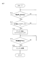
図2は、アイドルストップ制御の流れを示すフローチャートである。 FIG. 2 is a flowchart showing the flow of idle stop control.
アイドルストップ制御では、アイドルストップECU25により、所定の自動停止条件が成立しているか否かが繰り返し判断される(ステップS1)。自動停止条件は、たとえば、車速が9km/h以下であり、かつ、マスタシリンダの液圧(ブレーキ液圧)が0.4MPa以上であるという条件である。
In the idle stop control, the
自動停止条件が成立すると(ステップS1のYES)、アイドルストップECU25により、アイドルストップECU25のメモリに設けられたIDS禁止フラグがオフであるか否かが判定される(ステップS2)。IDS禁止フラグは、エンジン2のアイドルストップが禁止されているか否かを表すフラグである。
When the automatic stop condition is satisfied (YES in step S1), the
IDS禁止フラグがオンである場合には(ステップS2のNO)、自動停止条件が成立しているか否かが再び判断される(ステップS1)。 When the IDS prohibition flag is on (NO in step S2), it is determined again whether or not the automatic stop condition is satisfied (step S1).
自動停止条件が成立し、かつ、IDS禁止フラグがオフであれば(ステップS2のYES)、アイドルストップECU25からエンジンECU21にエンジン停止指令が出力され、エンジンECU21により、エンジン2が停止される(ステップS3)。
If the automatic stop condition is satisfied and the IDS prohibition flag is OFF (YES in Step S2), an engine stop command is output from the
このエンジン2の停止中は、アイドルストップECU25により、所定の再始動条件が成立したか否かが繰り返し判断される(ステップS4)。再始動条件は、たとえば、ブレーキペダルから足が放されたという条件である。
While the
ブレーキペダルから足が放されて、再始動条件が成立すると(ステップS4のYES)、アイドルストップECU25により、リレー12がオンされる。リレー12がオンされると、スタータ5によるクランキングを経て、エンジン2が始動し(ステップS5)、アイドルストップ制御が終了となる。
When the foot is released from the brake pedal and the restart condition is satisfied (YES in step S4), the
図3は、IDS禁止フラグ設定処理の流れを示すフローチャートである。図4は、操舵トルクおよびIDS禁止フラグの状態の変化の一例を示す図である。 FIG. 3 is a flowchart showing the flow of IDS prohibition flag setting processing. FIG. 4 is a diagram illustrating an example of changes in the state of the steering torque and the IDS prohibition flag.
アイドルストップ制御と並行して、アイドルストップECU25により、IDS禁止フラグ設定処理が繰り返し実行される。
In parallel with the idle stop control, the IDS prohibition flag setting process is repeatedly executed by the
IDS禁止フラグ設定処理では、まず、EPSECU24から入力される操舵トルク、つまりステアリング機構9のステアリングホイールに加えられている操舵トルクが所定のIDS禁止トルク閾値(第1トルク閾値)以上であるか否かが繰り返し判断される(ステップS11)。IDS禁止トルク閾値は、たとえば、0.5N・mに設定されている。
In the IDS prohibition flag setting process, first, whether or not the steering torque input from the
IDS禁止トルク閾値以上の操舵トルクがステアリングホイールに加えられると(ステップS11のYES)、アイドルストップECU25のメモリに設けられたIDS禁止フラグがオン(IDS禁止フラグに1が設定)される(ステップS12、時刻T1)。
When a steering torque equal to or greater than the IDS prohibition torque threshold is applied to the steering wheel (YES in step S11), the IDS prohibition flag provided in the memory of the
その後、EPSECU24から入力される操舵トルクが取得され、操舵トルクが所定のIDS許可トルク閾値(第2トルク閾値)未満に低下したか否かが繰り返し判断される(ステップS13)。IDS許可トルク閾値は、たとえば、IDS禁止トルク閾値と同じ値に設定されている。
Thereafter, the steering torque input from the
操舵トルクがIDS許可トルク閾値未満に低下すると(ステップS13のYES、時刻T2)、その時点からの経過時間(操舵トルクがIDS許可トルク閾値未満である状態が継続している時間)の計測が開始される。そして、その計測された時間が後述するディレイ時間設定処理によって設定されたディレイ時間(継続時間)に達したか否かが判断される(ステップS14)。 When the steering torque falls below the IDS permission torque threshold (YES in step S13, time T2), measurement of the elapsed time from that time (the time during which the state where the steering torque is less than the IDS permission torque threshold continues) starts. Is done. Then, it is determined whether or not the measured time has reached a delay time (duration) set by a delay time setting process described later (step S14).
操舵トルクがIDS許可トルク閾値未満である状態がディレイ時間にわたって継続するまでは(ステップS14のNO)、操舵トルクがIDS許可トルク閾値より小さいか否かが再び判断される(ステップS13)。 Until the state where the steering torque is less than the IDS permission torque threshold continues for the delay time (NO in step S14), it is determined again whether the steering torque is smaller than the IDS permission torque threshold (step S13).
操舵トルクがIDS許可トルク閾値未満である状態がディレイ時間にわたって継続する前に、操舵トルクがIDS許可トルク閾値以上に上昇すると(ステップS13のNO、時刻T3)、それまでに計測されている時間が0にクリアされる(ステップS15)。その後は、操舵トルクがIDS許可トルク閾値未満に低下したか否かが繰り返し判断される(ステップS13)。 If the steering torque rises above the IDS permission torque threshold before the state where the steering torque is less than the IDS permission torque threshold continues for the delay time (NO in step S13, time T3), the time measured so far It is cleared to 0 (step S15). Thereafter, it is repeatedly determined whether or not the steering torque has dropped below the IDS permission torque threshold (step S13).
そして、操舵トルクがIDS許可トルク閾値未満に低下し(時刻T4)、その状態がディレイ時間にわたって継続すると(ステップS14のYES)、IDS禁止フラグがオフ(IDS禁止フラグに0が設定)される(ステップS16、時刻T5)。 When the steering torque falls below the IDS permission torque threshold (time T4) and the state continues for the delay time (YES in step S14), the IDS prohibition flag is turned off (the IDS prohibition flag is set to 0) ( Step S16, time T5).
図5は、ディレイ時間設定処理の流れを示すフローチャートである。図6は、操舵トルクとディレイ時間との関係を示す図である。 FIG. 5 is a flowchart showing the flow of the delay time setting process. FIG. 6 is a diagram showing the relationship between the steering torque and the delay time.
アイドルストップ制御中、アイドルストップECU25により、ディレイ時間設定処理が繰り返し実行される。
During the idle stop control, the
ディレイ時間設定処理では、EPSECU24から入力される操舵トルクがIDS許可トルク閾値未満であるか否かが繰り返し判断される(ステップS21)。
In the delay time setting process, it is repeatedly determined whether or not the steering torque input from the
操舵トルクがIDS許可トルク閾値未満に低下すると(ステップS21のYES)、アイドルストップECU25のメモリに記憶されている操舵トルクの履歴、つまり現時点から所定時間遡った時点までの期間にメモリに書き込まれた操舵トルクが読み出される(ステップS22)。
When the steering torque falls below the IDS permission torque threshold value (YES in step S21), the steering torque history stored in the memory of the
そして、その操舵トルクの履歴に基づいてディレイ時間が設定される(ステップS23)。具体的には、メモリから読み出された操舵トルクの履歴の平均値が算出される。そして、図6に示される操舵トルク(履歴の平均値)とディレイ時間との関係に基づいて、操舵トルクの履歴の平均値に応じたディレイ時間が設定される。操舵トルクとディレイ時間との関係は、アイドルストップECU25のメモリに記憶されており、たとえば、操舵トルクが0.5N・mおよび1.0N・mであるときに、ディレイ時間がそれぞれ3秒間および5秒間に設定され、操舵トルクが0.5N・m以上の範囲で、操舵トルクが大きいほど、ディレイ時間が3秒間から単調に増大するように定められている。
Then, a delay time is set based on the history of the steering torque (step S23). Specifically, the average value of the steering torque history read from the memory is calculated. Then, based on the relationship between the steering torque (history average value) and the delay time shown in FIG. 6, the delay time corresponding to the average value of the steering torque history is set. The relationship between the steering torque and the delay time is stored in the memory of the
こうしてディレイ時間が設定されると、ディレイ時間設定処理が終了となる。 When the delay time is set in this way, the delay time setting process ends.
以上のように、所定の自動停止条件(車速が9km/h以下で、かつ、マスタシリンダの液圧が0.4MPa以上)が成立すると、エンジン2が自動停止される。たとえば、アイドルストップ車1が交差点の手前で直進横断待ちのために停止しているときに、自動停止条件が成立し、エンジン2が自動停止(アイドルストップ)されることにより、燃料の無駄な消費を抑えることによる燃費の向上を図ることができる。
As described above, when a predetermined automatic stop condition (the vehicle speed is 9 km / h or less and the hydraulic pressure of the master cylinder is 0.4 MPa or more) is satisfied, the
トルクセンサ29により、ステアリング機構9(ステアリングホイール)に加えられた操舵トルクが検出される。トルクセンサ29によって検出される操舵トルクがIDS禁止トルク閾値以上である場合に、エンジン2の自動停止が禁止される。たとえば、交差点における右左折待ちのための停車は、アイドルストップ車1の即時発進が要求される状況での停車である。アイドルストップ車1が交差点で右左折待ちのために停止しているときには、ステアリング機構9が左右一方に切り込まれ、その状態を保持するために、そのステアリング機構9にIDS禁止トルク閾値以上の操舵トルクが加えられることが多い。このとき、エンジン2の自動停止が禁止されることにより、右左折可能な状況になったときに、アイドルストップ車1を速やかに発進させて右左折を完了させることができる。
The
また、エンジン2の自動停止が禁止されている状態で、トルクセンサ29によって検出される操舵トルクがIDS許可トルク閾値未満に低下した場合に、その自動停止の禁止が直ちには解除されず、操舵トルクがIDS許可トルク閾値未満である状態がディレイ時間にわたって継続した後、自動停止の禁止が解除される。これにより、自動停止条件が成立する直前にステアリングホイールに操舵トルクが偶然に加えられていなかったが、交差点での右左折前や駐車場内での走行中など、エンジン2の自動停止が望ましくない状況下であるときに、エンジン2が自動停止されることを防止できる。
Further, in the state where the automatic stop of the
そして、エンジン2の自動停止が望ましくない状況下におけるエンジン2の自動停止を防止するために、舵角センサを必要としないので、舵角センサを追加して設けることによるコストアップを回避することができる。
And since the steering angle sensor is not required in order to prevent the automatic stop of the
また、アイドルストップ車1には、電動パワーステアリング装置7が搭載されており、電動パワーステアリング装置7に付随して、トルクセンサ29が備えられている。そのため、アイドルストップ車1では、そのトルクセンサ29を利用して、エンジン2の自動停止が望ましくない状況下におけるエンジン2の自動停止を防止することができる。よって、アイドルストップ車1では、コストの低減効果をより顕著に発揮することができる。
The
ディレイ時間は、トルクセンサ29によって検出される操舵トルクがIDS許可トルク閾値未満に低下した時点から遡った所定時間内にトルクセンサ29によって検出された操舵トルクに基づいて、その操舵トルクの値が大きいほど長い時間に設定される。
The delay time is such that the value of the steering torque is large based on the steering torque detected by the
この構成によれば、操舵トルクがIDS許可トルク閾値未満に低下してからエンジン2の自動停止の禁止が解除されるまでのディレイ時間をステアリング機構9の操作状況に応じた適切な時間に設定することができる。たとえば、修正操舵などの小操舵時には、ディレイ時間が短い時間に設定されるので、エンジン2の自動停止が必要以上に禁止されることを防止できる。一方、ステアリング機構9の積極的な操作による操舵時には、ディレイ時間が長い時間に設定されるので、エンジン2の自動停止が望ましくない状況下におけるエンジン2の自動停止を防止することができる。
According to this configuration, the delay time from when the steering torque drops below the IDS permission torque threshold to when the prohibition of the automatic stop of the
以上、本発明の一実施形態を説明したが、本発明は、さらに他の形態で実施することができる。 As mentioned above, although one Embodiment of this invention was described, this invention can be implemented with another form.
たとえば、前述の実施形態においては、アイドルストップECU25のメモリに記憶された所定時間内の操舵トルクの履歴の平均値に基づいて、ディレイ時間が設定されるとした。これに代えて、所定時間内の操舵トルクの履歴の最大値に基づいて、その最大値が大きいほど、ディレイ時間が長い時間に設定されてもよい。ただし、ディレイ時間が操舵トルクの平均値に基づいて設定される構成では、トルクセンサ29から出力される信号に混入するノイズの影響を排除することができる。
For example, in the above-described embodiment, the delay time is set based on the average value of the steering torque history within the predetermined time stored in the memory of the
また、所定時間内の操舵トルクの時間変化率(微分値)に基づいて、ディレイ時間が設定されてもよい。たとえば、その時間変化率が大きいほど、ディレイ時間が長い時間に設定されてもよい。 Also, the delay time may be set based on the time change rate (differential value) of the steering torque within a predetermined time. For example, the delay time may be set longer as the time change rate is larger.
また、IDS許可トルク閾値がIDS禁止トルク閾値と同じ値(たとえば、0.5N・m)に設定されているとしたが。IDS禁止トルク閾値とIDS許可トルク閾値とが互いに異なる値であってもよい。たとえば、IDS許可トルク閾値は、IDS禁止トルク閾値よりも小さくてもよい。 Also, the IDS permission torque threshold is set to the same value (for example, 0.5 N · m) as the IDS prohibition torque threshold. The IDS prohibition torque threshold and the IDS permission torque threshold may be different from each other. For example, the IDS permission torque threshold may be smaller than the IDS prohibition torque threshold.
さらにまた、アイドルストップの自動停止条件として、車速9km/h以下で、かつ、ブレーキ液圧(マスタシリンダの液圧)が0.4MPa以上であることとしたが、自動停止条件は、必ずしもこの条件に限定されない。 Furthermore, the automatic stop condition for idle stop is that the vehicle speed is 9 km / h or less and the brake fluid pressure (fluid pressure of the master cylinder) is 0.4 MPa or more. However, the automatic stop condition is not necessarily limited to this condition. It is not limited to.
その他、前述の構成には、特許請求の範囲に記載された事項の範囲で種々の設計変更を施すことが可能である。 In addition, various design changes can be made to the above-described configuration within the scope of the matters described in the claims.
1 アイドルストップ車(車両)
2 エンジン(駆動源)
9 ステアリング機構(ステアリングホイール)
25 アイドルストップECU(自動停止手段、禁止手段、禁止解除手段、継続時間設定手段)
29 トルクセンサ
1 Idle stop car (vehicle)
2 Engine (drive source)
9 Steering mechanism (steering wheel)
25 Idle stop ECU (automatic stop means, prohibition means, prohibition release means, duration setting means)
29 Torque sensor
Claims (1)
前記ステアリングホイールに加えられた操舵トルクを検出するためのトルクセンサと、
所定の自動停止条件が成立したことに応答して、前記駆動源を自動停止させる自動停止手段と、
前記トルクセンサによって検出される操舵トルクが所定の第1トルク閾値以上である場合に、前記自動停止手段による前記駆動源の自動停止を禁止する禁止手段と、
前記トルクセンサによって検出される操舵トルクが所定の第2トルク閾値未満である状態が所定の継続時間にわたって継続した場合に、前記禁止手段による自動停止の禁止を解除する禁止解除手段と、
前記トルクセンサによって検出される操舵トルクが前記第2トルク閾値未満に低下した時点から遡った所定時間内に前記トルクセンサによって検出された操舵トルクに基づいて、前記継続時間を設定する継続時間設定手段とを含み、
前記継続時間設定手段は、前記所定時間内の操舵トルクの値が大きいほど前記継続時間を長い時間に設定する、車両用制御装置。 A control device used for a vehicle that travels by a driving force generated by a driving source and whose traveling direction is changed by an operation of a steering wheel,
A torque sensor for detecting a steering torque applied to the steering wheel;
Automatic stop means for automatically stopping the drive source in response to the establishment of a predetermined automatic stop condition;
Prohibiting means for prohibiting automatic stop of the drive source by the automatic stop means when a steering torque detected by the torque sensor is not less than a predetermined first torque threshold;
A prohibition canceling means for canceling the prohibition of automatic stop by the prohibiting means when a state where the steering torque detected by the torque sensor is less than a predetermined second torque threshold value continues for a predetermined duration ;
A duration setting means for setting the duration based on the steering torque detected by the torque sensor within a predetermined time that goes back from the time point when the steering torque detected by the torque sensor falls below the second torque threshold. look including a door,
The duration control means sets the duration to a longer time as the value of the steering torque within the predetermined time is larger .
Priority Applications (1)
| Application Number | Priority Date | Filing Date | Title |
|---|---|---|---|
| JP2013092223A JP6143285B2 (en) | 2013-04-25 | 2013-04-25 | Vehicle control device |
Applications Claiming Priority (1)
| Application Number | Priority Date | Filing Date | Title |
|---|---|---|---|
| JP2013092223A JP6143285B2 (en) | 2013-04-25 | 2013-04-25 | Vehicle control device |
Publications (2)
| Publication Number | Publication Date |
|---|---|
| JP2014214661A JP2014214661A (en) | 2014-11-17 |
| JP6143285B2 true JP6143285B2 (en) | 2017-06-07 |
Family
ID=51940673
Family Applications (1)
| Application Number | Title | Priority Date | Filing Date |
|---|---|---|---|
| JP2013092223A Active JP6143285B2 (en) | 2013-04-25 | 2013-04-25 | Vehicle control device |
Country Status (1)
| Country | Link |
|---|---|
| JP (1) | JP6143285B2 (en) |
Families Citing this family (2)
| Publication number | Priority date | Publication date | Assignee | Title |
|---|---|---|---|---|
| JP6399475B2 (en) * | 2017-03-17 | 2018-10-03 | マツダ株式会社 | Vehicle control device |
| JP7210096B2 (en) * | 2018-03-23 | 2023-01-23 | ダイハツ工業株式会社 | Vehicle idling stop operation control device |
Family Cites Families (5)
| Publication number | Priority date | Publication date | Assignee | Title |
|---|---|---|---|---|
| FR2874657B1 (en) * | 2004-08-27 | 2009-10-09 | Peugeot Citroen Automobiles Sa | METHOD OF INHIBITING THE AUTOMATIC STOP CONTROL OF THE THERMAL MOTOR OF A VEHICLE DURING PARKING MANEUVERES |
| JP5415549B2 (en) * | 2009-09-29 | 2014-02-12 | 本田技研工業株式会社 | Idle stop control device |
| JP5493680B2 (en) * | 2009-10-15 | 2014-05-14 | 株式会社ジェイテクト | Motor control device and electric power steering device |
| JP5786299B2 (en) * | 2010-09-24 | 2015-09-30 | 日産自動車株式会社 | Engine control apparatus and engine control method for idle stop vehicle |
| DE102011016638A1 (en) * | 2011-04-09 | 2012-10-11 | GM Global Technology Operations LLC (n. d. Gesetzen des Staates Delaware) | Method for operating an internal combustion engine, control unit, computer program product, computer program and signal sequence |
-
2013
- 2013-04-25 JP JP2013092223A patent/JP6143285B2/en active Active
Also Published As
| Publication number | Publication date |
|---|---|
| JP2014214661A (en) | 2014-11-17 |
Similar Documents
| Publication | Publication Date | Title |
|---|---|---|
| JP5045815B2 (en) | Vehicle control system | |
| US9567965B2 (en) | Intelligent idle stop and go control device and method thereof | |
| JP6609375B2 (en) | Brake device and vehicle | |
| JP6156077B2 (en) | Vehicle control device | |
| US10012202B2 (en) | Vehicular engine control device | |
| JP2006321268A (en) | Economic running control method and economic running controlling device | |
| US20130311072A1 (en) | Power-steering control system | |
| WO2015198842A1 (en) | Vehicle control device and vehicle control method | |
| JP5382260B1 (en) | ENGINE RESTART CONTROL DEVICE, VEHICLE, AND VEHICLE CONTROL METHOD | |
| JP6312356B2 (en) | Vehicle control device | |
| JP6143285B2 (en) | Vehicle control device | |
| JP2011143875A (en) | Brake control device for vehicle | |
| JP2000265870A (en) | Control device for hybrid vehicle | |
| JP6454884B2 (en) | Automatic engine stop control device for vehicle | |
| JP5622005B2 (en) | Electric power steering control device for idle stop vehicle | |
| JP2005343248A (en) | Parking assist brake controlling device | |
| JP6041573B2 (en) | Vehicle control device | |
| JP5946293B2 (en) | Abnormality detection device for brake negative pressure sensor | |
| JP6287244B2 (en) | Brake control device for vehicle | |
| JP6406927B2 (en) | Vehicle control device | |
| JP2016070242A (en) | Control device for vehicle | |
| JP2008279854A (en) | Vehicle control device | |
| JP2013209973A (en) | Control device for vehicle | |
| KR101734251B1 (en) | Apparatus and method controlling mode for power streering system | |
| JP6236936B2 (en) | Automatic engine stop control device for vehicle |
Legal Events
| Date | Code | Title | Description |
|---|---|---|---|
| A621 | Written request for application examination |
Free format text: JAPANESE INTERMEDIATE CODE: A621 Effective date: 20160304 |
|
| A977 | Report on retrieval |
Free format text: JAPANESE INTERMEDIATE CODE: A971007 Effective date: 20170127 |
|
| A131 | Notification of reasons for refusal |
Free format text: JAPANESE INTERMEDIATE CODE: A131 Effective date: 20170207 |
|
| A521 | Request for written amendment filed |
Free format text: JAPANESE INTERMEDIATE CODE: A523 Effective date: 20170404 |
|
| TRDD | Decision of grant or rejection written | ||
| A01 | Written decision to grant a patent or to grant a registration (utility model) |
Free format text: JAPANESE INTERMEDIATE CODE: A01 Effective date: 20170502 |
|
| A61 | First payment of annual fees (during grant procedure) |
Free format text: JAPANESE INTERMEDIATE CODE: A61 Effective date: 20170502 |
|
| R150 | Certificate of patent or registration of utility model |
Ref document number: 6143285 Country of ref document: JP Free format text: JAPANESE INTERMEDIATE CODE: R150 |
|
| R250 | Receipt of annual fees |
Free format text: JAPANESE INTERMEDIATE CODE: R250 |
|
| R250 | Receipt of annual fees |
Free format text: JAPANESE INTERMEDIATE CODE: R250 |
|
| R250 | Receipt of annual fees |
Free format text: JAPANESE INTERMEDIATE CODE: R250 |
|
| R250 | Receipt of annual fees |
Free format text: JAPANESE INTERMEDIATE CODE: R250 |
|
| R250 | Receipt of annual fees |
Free format text: JAPANESE INTERMEDIATE CODE: R250 |