JP6141848B2 - Hydraulic sealing device for thermoplastic material discharge valve assembly - Google Patents
Hydraulic sealing device for thermoplastic material discharge valve assembly Download PDFInfo
- Publication number
- JP6141848B2 JP6141848B2 JP2014528505A JP2014528505A JP6141848B2 JP 6141848 B2 JP6141848 B2 JP 6141848B2 JP 2014528505 A JP2014528505 A JP 2014528505A JP 2014528505 A JP2014528505 A JP 2014528505A JP 6141848 B2 JP6141848 B2 JP 6141848B2
- Authority
- JP
- Japan
- Prior art keywords
- thermoplastic material
- seal
- cartridge casing
- primary seal
- valve assembly
- Prior art date
- Legal status (The legal status is an assumption and is not a legal conclusion. Google has not performed a legal analysis and makes no representation as to the accuracy of the status listed.)
- Expired - Fee Related
Links
Images


Classifications
-
- B—PERFORMING OPERATIONS; TRANSPORTING
- B05—SPRAYING OR ATOMISING IN GENERAL; APPLYING FLUENT MATERIALS TO SURFACES, IN GENERAL
- B05C—APPARATUS FOR APPLYING FLUENT MATERIALS TO SURFACES, IN GENERAL
- B05C5/00—Apparatus in which liquid or other fluent material is projected, poured or allowed to flow on to the surface of the work
- B05C5/02—Apparatus in which liquid or other fluent material is projected, poured or allowed to flow on to the surface of the work the liquid or other fluent material being discharged through an outlet orifice by pressure, e.g. from an outlet device in contact or almost in contact, with the work
- B05C5/027—Coating heads with several outlets, e.g. aligned transversally to the moving direction of a web to be coated
-
- F—MECHANICAL ENGINEERING; LIGHTING; HEATING; WEAPONS; BLASTING
- F16—ENGINEERING ELEMENTS AND UNITS; GENERAL MEASURES FOR PRODUCING AND MAINTAINING EFFECTIVE FUNCTIONING OF MACHINES OR INSTALLATIONS; THERMAL INSULATION IN GENERAL
- F16J—PISTONS; CYLINDERS; SEALINGS
- F16J15/00—Sealings
- F16J15/002—Sealings comprising at least two sealings in succession
-
- F—MECHANICAL ENGINEERING; LIGHTING; HEATING; WEAPONS; BLASTING
- F16—ENGINEERING ELEMENTS AND UNITS; GENERAL MEASURES FOR PRODUCING AND MAINTAINING EFFECTIVE FUNCTIONING OF MACHINES OR INSTALLATIONS; THERMAL INSULATION IN GENERAL
- F16J—PISTONS; CYLINDERS; SEALINGS
- F16J15/00—Sealings
- F16J15/16—Sealings between relatively-moving surfaces
- F16J15/162—Special parts or details relating to lubrication or cooling of the sealing itself
-
- F—MECHANICAL ENGINEERING; LIGHTING; HEATING; WEAPONS; BLASTING
- F16—ENGINEERING ELEMENTS AND UNITS; GENERAL MEASURES FOR PRODUCING AND MAINTAINING EFFECTIVE FUNCTIONING OF MACHINES OR INSTALLATIONS; THERMAL INSULATION IN GENERAL
- F16J—PISTONS; CYLINDERS; SEALINGS
- F16J15/00—Sealings
- F16J15/16—Sealings between relatively-moving surfaces
- F16J15/32—Sealings between relatively-moving surfaces with elastic sealings, e.g. O-rings
- F16J15/3204—Sealings between relatively-moving surfaces with elastic sealings, e.g. O-rings with at least one lip
- F16J15/3232—Sealings between relatively-moving surfaces with elastic sealings, e.g. O-rings with at least one lip having two or more lips
- F16J15/3236—Sealings between relatively-moving surfaces with elastic sealings, e.g. O-rings with at least one lip having two or more lips with at least one lip for each surface, e.g. U-cup packings
-
- F—MECHANICAL ENGINEERING; LIGHTING; HEATING; WEAPONS; BLASTING
- F16—ENGINEERING ELEMENTS AND UNITS; GENERAL MEASURES FOR PRODUCING AND MAINTAINING EFFECTIVE FUNCTIONING OF MACHINES OR INSTALLATIONS; THERMAL INSULATION IN GENERAL
- F16J—PISTONS; CYLINDERS; SEALINGS
- F16J15/00—Sealings
- F16J15/46—Sealings with packing ring expanded or pressed into place by fluid pressure, e.g. inflatable packings
- F16J15/48—Sealings with packing ring expanded or pressed into place by fluid pressure, e.g. inflatable packings influenced by the pressure within the member to be sealed
Description
本発明は、包括的にはシール機構に関し、より詳細にはホットメルト接着剤その他の熱可塑性材料の吐出弁組立体内で使用される液圧式シール装置に関する。 The present invention relates generally to sealing mechanisms, and more particularly to a hydraulic sealing device for use in a discharge valve assembly of hot melt adhesive or other thermoplastic material.
[関連出願の相互参照]
本特許出願は、2011年8月31日に出願された米国仮特許出願第61/573,089号に関連し、また、この米国仮特許出願に基づいており、有効にこの米国仮特許出願から変更された特許出願である。本願は、この米国仮特許出願の出願日の利益を主張する。
[Cross-reference of related applications]
This patent application is related to US Provisional Patent Application No. 61 / 573,089, filed on August 31, 2011, and is based on and is effectively modified from this US Provisional Patent Application. Patent application. This application claims the benefit of the filing date of this US provisional patent application.
例えば、ホットメルト接着剤その他の熱可塑性材料を出力または吐出する液体吐出システムのような従来の液体吐出システムでは、通常、吐出弁組立体が使用される。吐出弁組立体は往復移動する弁ステムを備えている。弁ステムには、弁座と協働する弁部材が固定されている。吐出弁組立体は、弁部材が弁座に対してその非着座位置すなわち開放位置に置かれているときにホットメルト接着剤その他の熱可塑性材料の吐出を実際に可能にするように、また、弁部材が弁座に対してその着座位置すなわち閉鎖位置に置かれているときにホットメルト接着剤その他の熱可塑性材料の吐出を阻止するように使用される。更に、従来の吐出弁組立体はシールカートリッジも備え、シールカートリッジは、吐出弁組立体からのホットメルト接着剤その他の熱可塑性材料の漏れを防止するシール機構を含む。シールカートリッジにはウィープホールが設けられ、ウィープホールからホットメルト接着剤その他の熱可塑性材料が効果的に流出して、シール機構が機能不全を起こしていること、および弁アセンブリの交換が必要であることを作業者に示すことができる。シール機構の一方の面がホットメルト接着剤その他の熱可塑性材料による圧力に晒され、一方でシール機構の他方の面が実質的に大気圧にあることから、シール機構の障壁を挟んで圧力差が実質的に規定される。このため、この一定の圧力差によって、ホットメルト接着剤その他の熱可塑性材料は、常に、シール機構を通過して押し出される傾向にある。しかし、シール機構の構造的完全性が変わらず維持されるかぎり、シールカートリッジおよび吐出弁組立体からのホットメルト接着剤その他の熱可塑性材料の漏れは実質的に存在しない。反対に、シール機構の構造的完全性が実際についに損なわれて実質的に機能しない場合、シールカートリッジおよび吐出弁組立体からのホットメルト接着剤その他の熱可塑性材料の漏れが発生する。 For example, in conventional liquid dispensing systems, such as liquid dispensing systems that output or dispense hot melt adhesives or other thermoplastic materials, a dispensing valve assembly is typically used. The discharge valve assembly includes a reciprocating valve stem. A valve member that cooperates with the valve seat is fixed to the valve stem. The discharge valve assembly may actually allow for the discharge of hot melt adhesive or other thermoplastic material when the valve member is in its non-sitting or open position relative to the valve seat, and It is used to prevent the discharge of hot melt adhesive or other thermoplastic material when the valve member is in its seated or closed position relative to the valve seat. In addition, conventional discharge valve assemblies also include a seal cartridge that includes a seal mechanism that prevents leakage of hot melt adhesive or other thermoplastic material from the discharge valve assembly. The seal cartridge is provided with a weep hole so that hot melt adhesive or other thermoplastic material can effectively flow out of the weep hole, causing the sealing mechanism to malfunction and the valve assembly to be replaced. This can be shown to the operator. Since one side of the sealing mechanism is exposed to pressure from a hot melt adhesive or other thermoplastic material, while the other side of the sealing mechanism is at substantially atmospheric pressure, a pressure differential across the barrier of the sealing mechanism Is substantially defined. For this reason, this constant pressure difference always tends to push hot melt adhesives and other thermoplastic materials through the sealing mechanism. However, as long as the structural integrity of the seal mechanism remains unchanged, there is substantially no leakage of hot melt adhesive or other thermoplastic material from the seal cartridge and discharge valve assembly. Conversely, if the structural integrity of the seal mechanism is finally compromised and does not function substantially, leakage of hot melt adhesive or other thermoplastic material from the seal cartridge and discharge valve assembly will occur.
ホットメルト接着剤その他の熱可塑性材料の吐出弁組立体の動作寿命は、従来、サイクル単位で測られる。従来のシール機構を利用する従来の吐出弁組立体は、通常、およそ250,000,000サイクルの動作寿命を有することができる。各サイクル中、弁ステムはシール機構を越えて往復移動する。弁ステムがその往復サイクル運動に従ってシール機構を越えて動くと、ホットメルト接着剤その他の熱可塑性材料は弁ステムに緊密に付着または粘着する傾向があり、従ってホットメルト接着剤その他の熱可塑性材料もシール機構を越えて往復移動する。結果として、シール機構を迂回してシールカートリッジの内部に実質的に流入するホットメルト接着剤その他の熱可塑性材料の分量が、シールカートリッジ内に含まれている空気または酸素に暴露される。この理由は、シールカートリッジが、上述したウィープホールを設けた結果として、周囲雰囲気に流体接続されているからである。従って、ホットメルト接着剤その他の熱可塑性材料のそのような分量は、実質的に、硬化した摩損原因材塊になる。従って、理解することができるように、この硬化した摩損原因材塊が上述したサイクル動作中にシール機構を越えて往復するたびに、硬化した摩損原因材塊がシール機構を摩損し始め、ついにはシール機構の機能不全を引き起こす。シール機構の機能不全が実際に発生する場合、また、ホットメルト接着剤その他の熱可塑性材料がシール機構を超えて著しく漏れ、それによって、漏れたホットメルト接着剤その他の熱可塑性材料が、ついにはシールカートリッジ内に形成されるウィープホールから漏出する。それにより、シール機構が実際に機能しておらず、吐出弁組立体の交換が必要であることを作業者に知らせる。 The operating life of a hot melt adhesive or other thermoplastic material discharge valve assembly is conventionally measured in cycles. Conventional discharge valve assemblies that utilize conventional sealing mechanisms can typically have an operational life of approximately 250,000,000 cycles. During each cycle, the valve stem moves back and forth beyond the seal mechanism. As the valve stem moves past the sealing mechanism according to its reciprocating cycle motion, hot melt adhesives and other thermoplastic materials tend to adhere or stick tightly to the valve stem, so hot melt adhesives and other thermoplastic materials also Reciprocates beyond the seal mechanism. As a result, an amount of hot melt adhesive or other thermoplastic material that bypasses the seal mechanism and substantially flows into the interior of the seal cartridge is exposed to air or oxygen contained within the seal cartridge. This is because the seal cartridge is fluidly connected to the ambient atmosphere as a result of providing the aforementioned weep holes. Thus, such an amount of hot melt adhesive or other thermoplastic material substantially becomes a hardened wear causing mass. Thus, as can be appreciated, each time this hardened wear causing mass reciprocates beyond the seal mechanism during the cycle operation described above, the hardened wear causing mass begins to wear the seal mechanism and eventually It causes malfunction of the sealing mechanism. If the malfunction of the sealing mechanism actually occurs, and also the hot melt adhesive or other thermoplastic material leaks significantly beyond the sealing mechanism, so that the leaked hot melt adhesive or other thermoplastic material eventually Leakage from a weep hole formed in the seal cartridge. This informs the operator that the seal mechanism is not actually functioning and that the discharge valve assembly needs to be replaced.
従って、当該技術分野において、シール装置の実効寿命およびホットメルト接着剤その他の熱可塑性材料の吐出弁組立体の実効寿命が著しく増加する、ホットメルト接着剤その他の熱可塑性材料の吐出弁組立体内で使用される新規の改善されたシール装置が必要とされている。 Accordingly, in the art, there is a significant increase in the effective life of a sealing device and the effective life of a hot melt adhesive or other thermoplastic material discharge valve assembly within a hot melt adhesive or other thermoplastic material discharge valve assembly. There is a need for new and improved sealing devices that are used.
本発明の教示および原理に従って、ホットメルト接着剤その他の熱可塑性材料の吐出弁組立体内で使用される新規の改善されたシール装置の提供により、上記の目的および他の目的が達成される。この場合、新規の改善されたシール装置は、第1のシール部材すなわち一次シール部材と、二次シール部材と、シールカートリッジすなわちケーシング内に内部配置される粘性の非圧縮性シリコーングリースまたは同様の液体とを含むシールカートリッジすなわちケーシングを備える。粘性シリコーングリースまたは同様の液体は、圧力を効果的に分散して、シリコーングリースまたは同様の液体内の内部圧力をホットメルト接着剤その他の熱可塑性材料の外部圧力と実質的に等しくするようになっており、それによって、一次シール部材を挟んだ圧力差を効果的に排除し、それによりホットメルト接着剤その他の熱可塑性材料が漏洩する傾向すなわち漏れやすさが排除される。更に、粘性シリコーングリースまたは同様の液体は潤滑剤として機能し、それにより一次シール部材および二次シール部材の摩擦および摩耗が低減し、それによりホットメルト接着剤の吐出弁組立体のサイクル動作および寿命を例えば2倍または3倍等に著しく増加させることができる。そのため動作サイクルは、およそ500,000,000回〜750,000,000回の範囲内とすることができる。 In accordance with the teachings and principles of the present invention, the above and other objects are achieved by providing a new and improved sealing device for use in a discharge valve assembly of a hot melt adhesive or other thermoplastic material. In this case, the new and improved sealing device includes a first seal member or primary seal member, a secondary seal member, and a viscous incompressible silicone grease or similar liquid disposed within a seal cartridge or casing. A seal cartridge or casing. Viscous silicone grease or similar liquids effectively distribute the pressure so that the internal pressure in the silicone grease or similar liquid is substantially equal to the external pressure of the hot melt adhesive or other thermoplastic material. This effectively eliminates the pressure differential across the primary seal member, thereby eliminating the tendency for hot melt adhesives and other thermoplastic materials to leak, i.e., the likelihood of leakage. In addition, the viscous silicone grease or similar liquid functions as a lubricant, thereby reducing the friction and wear of the primary and secondary seal members, thereby cycling the hot melt adhesive discharge valve assembly and life. Can be significantly increased, for example, 2 or 3 times. Therefore, the operating cycle can be in the range of approximately 500,000,000 to 750,000,000 times.
本発明の種々の他の特徴および付随する利点は、添付の図面とともに考慮すると以下の詳細な説明からより完全に理解される。添付図面では、同様の参照符号は、いくつかの図を通して同様のまたは対応する部分を示している。 Various other features and attendant advantages of the present invention will become more fully understood from the following detailed description when considered in conjunction with the accompanying drawings. In the accompanying drawings, like reference numerals designate like or corresponding parts throughout the several views.
ここで図面、より具体的には図面の図1A、1Bを参照すると、新規の改善されたホットメルト接着剤その他の熱可塑性材料の吐出弁組立体が開示され、全体的に参照符号100によって示されている。吐出弁組立体は、本発明の新規の改善されたシール装置を内部に組み込み、本発明の原理および教示に従って構成されている。より具体的には、本発明の新規の改善された吐出弁組立体100は、ホットメルト接着剤その他の熱可塑性材料の塗布動作若しくは吐出動作または塗布サイクル若しくは吐出サイクル中に、生産工程ラインに沿って基材または製品が吐出弁組立体100の下方を通過する際に、下方に位置する基材または製品上にホットメルト接着剤その他の熱可塑性材料を吐出するのに用いることができる。吐出弁組立体100は、以下でより完全に開示される吐出弁を収容する弁本体部分すなわちハウジング102と、同様に以下でより完全に開示される、吐出弁の垂直往復運動を制御する吐出弁アクチュエーター組立体104と、以下でより完全に開示される吐出弁の往復運動を制御するように吐出弁アクチュエーター組立体104に対する制御用空気の配置を制御する電空ソレノイド集成体106と、ホットメルト接着剤その他の熱可塑性材料の放出すなわち吐出を提供する放出マニフォールド組立体108とを備えていることがわかる。
Referring now to the drawings, and more particularly to FIGS. 1A and 1B of the drawings, a new and improved hot melt adhesive and other thermoplastic material discharge valve assembly is disclosed and generally designated by the
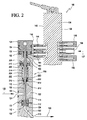
ここで図2を参照すると、弁本体部分すなわちハウジング102は、垂直に往復する弁ステム110が内部に配置されていることがわかる。弁部材112が弁ステム110の下端部に取付、固定けされており、また、弁座114が、弁本体部分すなわちハウジング102の下端部と放出マニフォールド組立体108の上端部との間に形成される接続部に効果的に配置されていることがわかる。放出マニフォールド組立体108は、ホットメルト接着剤その他の熱可塑性材料の放出ポート116と、ホットメルト接着剤その他の熱可塑性材料の吐出ポート118と、ホットメルト接着剤その他の熱可塑性材料の放出流路122とを更に含んでいることがわかる。吐出ポート118から、ホットメルト接着剤その他の熱可塑性材料を120において示されているように吐出することができる。放出流路122は、放出マニフォールド組立体108内に形成され、ホットメルト接着剤その他の熱可塑性材料の放出ポート116を、ホットメルト接着剤その他の熱可塑性材料の吐出ポート118に流体接続する。更に、ホットメルト接着剤その他の熱可塑性材料の入口供給ポート124が、また弁本体部分すなわちハウジング102内に設けられて、ホットメルト接着剤その他の熱可塑性材料を126におけるように吐出弁組立体100内に導く。また更に、弁本体部分すなわちハウジング102には縦向きの流体通路128も設けられる。流体通路128は、弁ステム110を環状に囲むとともに、同様に弁本体部分すなわちハウジング102内に形成される横向きの流体導管すなわち流体通路130によって、ホットメルト接着剤その他の熱可塑性材料の入口供給ポート124に流体接続される。
Referring now to FIG. 2, it can be seen that the valve body portion or
従って、以下のことを理解することができる。図2に示すように弁ステム110がその下降位置に向かって移動される場合、弁部材112は弁座114に対して非着座位置すなわち開放位置に置かれる。それによってホットメルト接着剤その他の熱可塑性材料が、ホットメルト接着剤その他の熱可塑性材料の入口供給ポート124から、横向きの流体導管すなわち流体通路130を通って、弁ステム110を環状に囲む縦向きの流体通路128内へ、そして、弁部材112が弁座114に対して着座していない、すなわち開放しているため、弁座114内に形成されるとともに弁ステム110を環状に囲む、弁部材112の回りの縦向きの通路132内、弁座114の下方部分に形成されるチャンバー134内へと流れ、ホットメルト接着剤その他の熱可塑性材料の放出ポート116、ホットメルト接着剤その他の熱可塑性材料の放出流路122、そしてホットメルト接着剤その他の熱可塑性材料の吐出ポート118を通って出ることができる。対照的に、弁ステム110がその上側位置すなわち上昇位置に置かれる場合、弁部材112は弁座114に対して着座位置すなわち閉鎖位置に置かれる。それによって、ホットメルト接着剤その他の熱可塑性材料の液体流が停止される。
Therefore, the following can be understood. When the
図2を更に参照すると、電空ソレノイド集成体106は、制御用空気137が電空ソレノイド集成体106に入ることを可能にする、電空ソレノイド集成体106の一方の側壁部138に取付、固定けられる制御用空気投入継手と、同様に電空ソレノイド集成体106の側壁部138に取付、固定けられる制御用空気放出継手140、142の対とを有しており、弁ステム110および弁部材112の垂直配置を制御することがわかる。これに対応して、制御用空気投入/放出継手144、146の対が、その第1の端部を電空ソレノイド集成体106の反対側の側壁部148に取付、固定けられ、一方で制御用空気投入/放出継手144、146の第2の端部は吐出弁アクチュエーター組立体104の側壁部150に取付、固定けられている。ピストン152が弁ステム110の上部に取付、固定けられていること、およびピストン152が吐出弁アクチュエーター組立体104の実質的な中央領域に形成されるピストンチャンバー154内で垂直方向に往復運動可能であることが更にわかる。コイルばね156が、また弁ステム110の上部の回りに環状配置され、この場合コイルばね156の両端は、それぞれピストン152の下面部および吐出弁アクチュエーター組立体104の中央領域に形成される座繰り領域158、160内に配置される。
With further reference to FIG. 2,
また、電空ソレノイド集成体106には図示されていない流体通路が設けられ、この流体通路は制御用空気放出継手140、142の対と制御用空気投入/放出継手144、146の対とを相互に流体接続する。同様にして吐出弁アクチュエーター組立体104には同様にまた図示されていない流体通路も設けられ、この流体通路は制御用空気投入/放出継手144、146の対をピストン152の上方および下方のピストンチャンバー154の領域に相互に流体接続する。以上のことが更に理解される。従ってそれに応じて、制御用空気137が、例えば電空ソレノイド集成体106の制御用空気投入継手136に導かれる場合、かつ電空ソレノイド集成体106が第1のモードで動作する場合、制御用空気137は、制御用空気投入継手136から、第1の制御用空気投入/放出継手144内、そしてピストンチャンバー154の上部内すなわちピストン152の上方に位置するピストンチャンバー154の領域内に流動的に導かれ、ピストン152、弁ステム110および弁部材112を付勢して弁部材の非着座位置すなわち開放位置に向かって下方に移動させることを理解することができる。同時に、ピストンチャンバー154の下方部分内の空気すなわちピストン152の下方の空気は、外方に圧送されて、第2の制御用空気投入/放出継手146および制御用空気放出継手のうちの第1の継手140を通って大気に排出される。反対に、電空ソレノイド集成体106が第2のモードで動作する場合、制御用空気137は、制御用空気投入継手136から、第2の制御用空気投入/放出継手146内、そしてピストンチャンバー154の下方部分内すなわちピストン152の下方に位置するピストンチャンバー154の領域内に流動的に導かれ、ピストン152、弁ステム110および弁部材112を付勢して弁部材の着座位置すなわち閉鎖位置に向かって上方に移動させる。同時に、ピストンチャンバー154の上部内の空気すなわちピストン152の上方の空気は、第1の制御用空気投入/放出継手144および制御用空気放出継手のうちの第2の継手142を通って外方に排出される。以下のことが最後に留意される。ピストン152は、通常、弁部材112が弁座114に対して着座位置すなわち閉鎖位置に置かれるその上側位置に向かってばね付勢されている。これと同時に、ピストン152をその上側位置に移動させるように制御用空気を提供することは、コイルばね156による付勢を効果的に補助し、ピストン152および弁ステム110、ひいては弁部材112をその着座位置すなわち閉鎖位置に迅速に移動させるのに役立つ。
In addition, the
更に続けて、図2と併せて図3を加えて参照して、全体的に参照符号200によって示されている本発明の新規の改善されたシール装置がここで説明される。シール装置200は、シールカートリッジすなわちケーシング202を備えていることがわかる。ケーシング202はチャンバー204内に配置、固定されるように構成され、チャンバー204は弁本体部分すなわちハウジング102の上方軸方向部分に形成される。シールカートリッジすなわちケーシング202の最上部には閉込ワッシャ206および保持リング208が設けられる。図2、3からは、保持リング208が、シールカートリッジすなわちケーシング202の直径長よりも直径が大きく、ケーシング202から径方向外方に延出していることが理解される。環状座繰り領域210が弁本体部分すなわちハウジング102の上端部内に形成され、図2において最も良く見てとることができるようにシールカートリッジすなわちケーシング202の保持リング208を収容するように構成され、シールカートリッジすなわちケーシング202が弁本体部分すなわちハウジング102内に実際に取付、固定けられるようになっている。シールカートリッジすなわちケーシング202の下端部はまた、環状肩部212に着座するものとして留意される。環状肩部212はまたチャンバー204の底領域を実質的に形成する。従来のように、シールカートリッジすなわちケーシング202は弁ステム110を環状に囲んで環状スペースすなわちチャンバー214を形成するが、従来のシールカートリッジすなわちケーシングと異なり、シールカートリッジすなわちケーシング202は空ではなくウィープホールを有しない。対照的に、シールカートリッジすなわちケーシング202の環状スペースすなわちチャンバー214は、高温の粘性シリコーングリースまたは同様の液体によって充填されている。
Continuing with reference to FIG. 3 in conjunction with FIG. 2, a novel and improved sealing apparatus of the present invention, generally designated by the
更に、本発明のシール装置200は、上述したシリコーングリースまたは同様の液体とともに動作するシール部材を備え、ホットメルト接着剤その他の熱可塑性材料は、シール装置200を通過して、吐出弁アクチュエーター組立体104のピストンチャンバー154内に入り、それによってピストン152の動作が損なわれることを効果的に防止する。より具体的には、シール装置200は、弁ステム110の中央部を環状に囲むとともに、シールカートリッジすなわちケーシング202の下端部内で垂直往復するように取り付けられる第1のシール部材すなわち一次シール部材216を備える。第1のワッシャ218および第2のワッシャ220が、一次シール部材216と連動し、予負荷ばねすなわち圧縮ばね222が、第1のワッシャ218と第2のワッシャ220との間に形成されるチャンバー223内に配置される結果として、第1のワッシャ218と第2のワッシャ220との間に介在する。全体的な周囲関係すなわち空間関係に関して図2も参照して図3から最も良く理解することができるように、ホットメルト接着剤その他の熱可塑性材料が、126におけるように入口供給ポート124によってホットメルト接着剤その他の熱可塑性材料の吐出弁組立体に入ると、流入する加圧ホットメルト接着剤その他の熱可塑性材料の性質による動作圧が、参照矢印224によって示されるように一次シール部材216の下面部に印加される。
Furthermore, the
それに応じて、チャンバー223も粘性シリコーングリースまたは同様の液体を収容して環状スペースすなわちチャンバー214内に位置する粘性シリコーングリースまたは同様の液体に流体接続しているため、上向きの圧力224が一次シール部材216を上方に移動させ、そのような移動が予負荷ばねすなわち圧縮ばね222を圧縮し、この圧力は環状スペースすなわちチャンバー214内に位置する粘性シリコーングリースまたは同様の液体に更に伝達される。シールカートリッジすなわちケーシング202の上部にはまた、二次シール部材226が設けられるが、二次シール部材226は上方に移動することができない。その理由は、シールカートリッジすなわちケーシング202の上部が閉込ワッシャ206および保持リング208によって効果的に閉鎖されているからである。また、粘性シリコーングリースまたは液体が非圧縮性液体を含むため、粘性シリコーングリースまたは同様の液によって圧力228、230が弁ステム110および二次シール部材226の下面部にそれぞれ印加される。従って、シールカートリッジすなわちケーシング202内が静圧状態となり、それによって、非圧縮性の粘性シリコーングリースまたは同様の液体の性質による内部圧力228、230がホットメルト接着剤その他の熱可塑性材料の性質による外部圧力224に等しくなる。
Accordingly,
従って、本発明のシール装置200を用いて、第1のシール部材すなわち一次シール部材216を挟んで通常存在する圧力差がもはや存在せず、それによりホットメルト接着剤その他の熱可塑性材料が漏洩する傾向すなわち漏れやすさが効果的に排除されることを更に理解すなわち認識することができる。サイクル動作中すなわち弁部材112がその着座位置すなわち閉鎖位置とその非着座位置すなわち開放位置との間で移動するとき、ホットメルト接着剤その他の熱可塑性材料の性質による圧力は変化することが留意される。往復する第1のシール部材すなわち一次シール部材216は、圧力のそのような変化を動的に相殺する。傾斜ばね部材232、234が、一次シール部材216および二次シール部材226内にそれぞれ内部配置されて、一次シール部材216および二次シール部材226の構造的完全性および構成を維持するのを助け、一次シール部材216および二次シール部材226が、例えば弁ステム110およびシールカートリッジすなわちケーシング202に対する自身のシール機能を果たすことを可能にすることが留意される。更に、一次シール部材216および二次シール部材226は例えばポリエーテルエーテルケトン(PEEK)または同様の材料等の好適な材料から作製することができる。
Thus, with the
シールカートリッジすなわちケーシング202内の内部で粘性シリコーングリースまたは同様の液体を使用すなわち利用することは、更なる理由から重要であることも留意される。第1に、例えば粘性シリコーングリースまたは同様の液体は潤滑剤である。従って層流特性に起因して、少量のシリコーングリースまたは同様の液体が、極薄膜層として弁ステム110または一次シール部材216若しくは二次シール部材226に緊密に付着または粘着することができる。従って、弁ステム110がそのサイクル往復運動を行う際に弁ステム110と一次シール部材216または二次シール部材226との間に発生する摩擦が著しく低減する。第2に、粘性シリコーングリースまたは同様の液体の潤滑性の結果として、ホットメルト接着剤その他の熱可塑性材料が実際に弁ステムに緊密に付着または粘着する傾向が著しく低減される。第3に、ホットメルト接着剤その他の熱可塑性材料の同様の層流特性に起因して、シリコーングリースまたは同様の液体の上述の潤滑特性にもかかわらず、それでもやはり少量のホットメルト接着剤その他の熱可塑性材料が、極薄膜層として弁ステム110にこびりつく、すなわち付着し、例えば第1のシール部材すなわち一次シール部材216を実質的に越えて進む可能性がある。しかし、そのようなことが実際に起こる場合、かつホットメルト接着剤その他の熱可塑性材料が弁ステム110から離れる場合、ホットメルト接着剤その他の熱可塑性材料は、粘性シリコーングリースまたは同様の液体内に効果的に封じ込められる。第4に、上述したように粘性シリコーングリースまたは同様の液体内にホットメルト接着剤その他の熱可塑性材料を封じ込める結果として、ホットメルト接着剤その他の熱可塑性材料は周囲空気または酸素に実際に暴露されず、そのため、ホットメルト接着剤その他の熱可塑性材料は、硬化して従来のようにシール部材に作用する摩損原因材塊になる可能性がない。
It is also noted that the use or utilization of viscous silicone grease or similar liquid within the seal cartridge or
以下のことを最後に留意する。本発明の新規の改善されたシール装置200の結果として、シール点すなわち障壁が、シール装置200の下端部に位置する一次シール部材216からシール装置200の上端部に位置する二次シール部材226に効果的に移される。これの理由は、一次シール部材216においては、このシール部材、シール点すなわち障壁216を挟んだ圧力224、228は実質的に均一にされ、本明細書の上記で説明したように、圧力差がもはや存在しないようになっており、一方で二次シール部材226においては、内部圧力230が、大気圧力である外部圧力よりも比較的大きいことにより圧力差が存在するからである。これは、二次シール部材226が、ホットメルト接着剤その他の熱可塑性材料によって通常引き起こされるいかなる有害な影響からも効果的に保護される点で重要である。
Finally, note the following: As a result of the new and
明らかに、上記の教示に鑑みて本発明の多くの変形形態および変更形態が可能である。従って、添付の特許請求の範囲の範囲内で、本発明は本明細書に具体的に記載されているものとは別様に実施することができることが理解されよう。 Obviously, many modifications and variations of the present invention are possible in light of the above teachings. It is therefore to be understood that within the scope of the appended claims, the invention may be practiced otherwise than as specifically described herein.
100 吐出弁組立体
102 ハウジング
104 吐出弁アクチュエーター組立体
106 電空ソレノイド集成体
108 放出マニフォールド組立体
110 弁ステム
112 弁部材
114 弁座
116 放出ポート
118 吐出ポート
122 放出流路
124 入口供給ポート
128 流体通路
130 流体通路
132 通路
134 チャンバー
136 制御用空気投入継手
137 制御用空気
138 側壁部
140 第1の継手
142 第2の継手
144 放出継手
146 放出継手
148 側壁部
150 側壁部
152 ピストン
154 ピストンチャンバー
200 シール装置
202 ケーシング
204 チャンバー
206 閉込ワッシャ
208 保持リング
212 環状肩部
214 チャンバー
216 第1の一次シール部材
216 障壁
218 第1のワッシャ
220 第2のワッシャ
223 チャンバー
226 二次シール部材
DESCRIPTION OF
Claims (18)
熱可塑性材料の吐出弁組立体の弁ステムの回りに環状配置されるように構成され、前記弁ステムとともに環状スペースを形成するカートリッジケーシングと、
前記カートリッジケーシングの第1の端部に位置するとともに、前記弁ステムの回りに環状配置され、前記弁ステムと前記カートリッジケーシングとの間に形成される環状スペースを、前記カートリッジケーシングの第1の端部においてシールする一次シールと、
前記カートリッジケーシングの第2の端部に位置するとともに、前記弁ステムの回りに環状配置され、前記弁ステムと前記カートリッジケーシングとの間に形成される前記環状スペースを、前記カートリッジケーシングの第2の端部においてシールする二次シールと、
前記弁ステムと前記カートリッジケーシングとの間に形成される前記環状スペース内に配置された粘性の非圧縮性液体とを具備し、
前記一次シールが配置されている環状スペースは、前記粘性の非圧縮性液体が配置された環状スペースよりも直径が大きくなっており、
前記一次シールが配置された環状スペース内において、前記一次シールと前記二次シールとの間には、一対のワッシャと、該一対のワッシャの間に配置された予負荷ばねとが配置されており、
前記熱可塑性材料の吐出弁組立体の前記熱可塑性材料によって前記一次シールに印加される外部圧力を前記粘性の非圧縮性液体を通して効果的に分散し、それにより、該粘性の非圧縮性液体内の内部圧力が、前記熱可塑性材料の吐出弁組立体の前記熱可塑性材料によって前記一次シールに印加される前記外部圧力と実質的に等しくなり、それにより、前記一次シールを挟んだ圧力差が効果的に排除され、前記熱可塑性材料が前記カートリッジケーシング内に漏洩するようにした液圧式シール装置。 In a hydraulic seal device used in a discharge valve assembly of thermoplastic material ,
A cartridge casing configured to be annularly disposed about a valve stem of a discharge valve assembly of thermoplastic material and forming an annular space with the valve stem ;
While located at a first end of the cartridge casing, is an annular arrangement around said valve stem, an annular space formed between the valve stem and the cartridge casing, a first end of said cartridge casing A primary seal that seals at the part;
Located at the second end of the cartridge casing and annularly disposed around the valve stem , the annular space formed between the valve stem and the cartridge casing is defined as the second of the cartridge casing. A secondary seal that seals at the end;
A viscous incompressible liquid disposed in the annular space formed between the valve stem and the cartridge casing;
The annular space in which the primary seal is disposed has a larger diameter than the annular space in which the viscous incompressible liquid is disposed;
In the annular space in which the primary seal is disposed, a pair of washers and a preload spring disposed between the pair of washers are disposed between the primary seal and the secondary seal. ,
Effectively disperses the external pressure applied to the primary seal by the thermoplastic material of the thermoplastic material discharge valve assembly through the viscous incompressible liquid, and thereby within the viscous incompressible liquid. The internal pressure of the thermoplastic material discharge valve assembly is substantially equal to the external pressure applied to the primary seal by the thermoplastic material so that the pressure differential across the primary seal is effective. A hydraulic sealing device that is eliminated and allows the thermoplastic material to leak into the cartridge casing.
熱可塑性材料を該熱可塑性材料の吐出弁組立体内に供給する、熱可塑性材料の入口供給ポートと、
熱可塑性材料を該熱可塑性材料の吐出弁組立体から吐出する、熱可塑性材料の吐出ポートと、
弁ステムと、
弁座と、
前記弁ステムに配置、固定されるとともに前記弁座と動作的に協働するように構成され、該弁部材が非着座位置すなわち開放位置に置かれると、熱可塑性材料を吐出することができ、一方で該弁部材が着座位置すなわち閉鎖位置に置かれていると、熱可塑性材料を吐出することができないようになっている弁部材と、
該弁ステムの回りに環状配置されるように構成され、該弁ステムとともに環状スペースを形成するカートリッジケーシングと、
前記カートリッジケーシングの第1の端部に位置するとともに該弁ステムの回りに環状配置され、該弁ステムと前記カートリッジケーシングとの間に形成される環状スペースを、前記カートリッジケーシングの第1の端部においてシールする一次シールと、
前記カートリッジケーシングの第2の端部に位置するとともに該弁ステムの回りに環状配置され、該弁ステムと前記カートリッジケーシングとの間に形成される前記環状スペースを、前記カートリッジケーシングの第2の端部においてシールする二次シールと、
該弁ステムと前記カートリッジケーシングとの間に形成される前記環状スペース内に配置された粘性の非圧縮性液体とを具備し、
前記一次シールが配置されている環状スペースは、前記粘性の非圧縮性液体が配置された環状スペースよりも直径が大きくなっており、
前記一次シールが配置された環状スペース内において、前記一次シールと前記二次シールとの間には、一対のワッシャと、該一対のワッシャの間に配置された予負荷ばねとが配置されており、
該熱可塑性材料の吐出弁組立体の前記熱可塑性材料によって前記一次シールに印加される外部圧力を、該弁ステムと前記カートリッジケーシングとの間に形成される前記環状スペース内の該粘性の非圧縮性液体を通して効果的に分散し、それにより、該粘性の非圧縮性液体内の内部圧力は、該熱可塑性材料の吐出弁組立体の前記熱可塑性材料によって前記一次シールに印加される前記外部圧力と実質的に等しくなり、それにより、前記一次シールを挟んだ圧力差が効果的に排除され、前記熱可塑性材料が前記カートリッジケーシング内に漏洩することを防止するようにした熱可塑性材料の吐出弁組立体。 In the discharge valve assembly of thermoplastic material ,
The thermoplastic material is supplied to the discharge valve assembly of the thermoplastic material, and inlet feed port of the thermoplastic material,
The thermoplastic material discharged from the discharge valve assembly of the thermoplastic material, and a discharge port of a thermoplastic material,
A valve stem;
A valve seat,
Arranged and fixed to the valve stem and configured to operatively cooperate with the valve seat, and when the valve member is placed in a non-sitting position or an open position, the thermoplastic material can be discharged; On the other hand, when the valve member is placed in a seating position, that is, a closed position, the valve member is configured so as not to be able to discharge thermoplastic material ;
Is configured to be an annular arrangement around the valve stem, a cartridge casing forming an annular space with said valve stem,
Wherein while located at a first end of the cartridge casing is an annular arrangement around the valve stem, the annular space formed between said valve stem and said cartridge casing, a first end of the cartridge casing A primary seal for sealing at
Wherein together located at the second end of the cartridge casing is an annular arrangement around the valve stem, the annular space formed between said valve stem and said cartridge casing, the second end of said cartridge casing A secondary seal that seals at the part;
Comprising the incompressible viscous liquid disposed in said annular space formed between said valve stem and said cartridge casing,
The annular space in which the primary seal is disposed has a larger diameter than the annular space in which the viscous incompressible liquid is disposed;
In the annular space in which the primary seal is disposed, a pair of washers and a preload spring disposed between the pair of washers are disposed between the primary seal and the secondary seal. ,
The external pressure applied to the primary seal by the thermoplastic material of the discharge valve assembly of the thermoplastic material, viscous uncompressed in the annular space formed between said valve stem and said cartridge casing effectively dispersed through sexual liquid, whereby the internal pressure of the incompressible in the liquid of the pressure-sensitive properties, the external pressure by the thermoplastic material of the discharge valve assembly of the thermoplastic material is applied to the primary seal substantially equal, whereby the pressure differential across the primary seal is effectively eliminated, the discharge valve of a thermoplastic material as the thermoplastic material is prevented from leaking into the cartridge casing Assembly.
Applications Claiming Priority (5)
| Application Number | Priority Date | Filing Date | Title |
|---|---|---|---|
| US201161573089P | 2011-08-31 | 2011-08-31 | |
| US61/573,089 | 2011-08-31 | ||
| US13/534,018 | 2012-06-27 | ||
| US13/534,018 US20130048900A1 (en) | 2011-08-31 | 2012-06-27 | Hydraulic seal assembly for a thermoplastic material dispensing valve assembly |
| PCT/US2012/052594 WO2013033053A1 (en) | 2011-08-31 | 2012-08-28 | Hydraulic seal assembly for a thermoplastic material dispensing valve assembly |
Publications (3)
| Publication Number | Publication Date |
|---|---|
| JP2014527145A JP2014527145A (en) | 2014-10-09 |
| JP2014527145A5 JP2014527145A5 (en) | 2015-10-15 |
| JP6141848B2 true JP6141848B2 (en) | 2017-06-07 |
Family
ID=47742288
Family Applications (1)
| Application Number | Title | Priority Date | Filing Date |
|---|---|---|---|
| JP2014528505A Expired - Fee Related JP6141848B2 (en) | 2011-08-31 | 2012-08-28 | Hydraulic sealing device for thermoplastic material discharge valve assembly |
Country Status (7)
| Country | Link |
|---|---|
| US (1) | US20130048900A1 (en) |
| EP (1) | EP2751450B1 (en) |
| JP (1) | JP6141848B2 (en) |
| CN (1) | CN103748389B (en) |
| ES (1) | ES2558358T3 (en) |
| PL (1) | PL2751450T3 (en) |
| WO (1) | WO2013033053A1 (en) |
Families Citing this family (5)
| Publication number | Priority date | Publication date | Assignee | Title |
|---|---|---|---|---|
| CN108262219B (en) * | 2018-03-27 | 2023-04-28 | 深圳市世椿智能装备股份有限公司 | Liquid sealing type valve assembly |
| US20220048062A1 (en) * | 2019-04-05 | 2022-02-17 | Nordson Corporation | Applicator air manifold |
| CN111584409B (en) * | 2020-06-02 | 2020-11-17 | 温州华邦安全封条股份有限公司 | Device for automatically coating silicon grease on chip |
| CN113369105B (en) * | 2021-06-18 | 2022-07-15 | 广西玉柴机器股份有限公司 | Oil sprayer blocking rod for mounting cylinder head cover |
| KR102591729B1 (en) * | 2021-12-13 | 2023-10-23 | 주식회사 쓰리젯 | Rising stem ball valve with casing for sealing stem |
Family Cites Families (38)
| Publication number | Priority date | Publication date | Assignee | Title |
|---|---|---|---|---|
| US1994830A (en) * | 1932-12-28 | 1935-03-19 | Universal Oil Seal Company | Oil seal |
| US2210826A (en) * | 1939-04-19 | 1940-08-06 | James H Williams | Fluid packing |
| US2308475A (en) * | 1941-08-07 | 1943-01-12 | Crane Co | Spring loaded stuffing box |
| US3199876A (en) * | 1963-06-10 | 1965-08-10 | Crane Co | Stuffing box construction |
| US3277797A (en) * | 1964-03-26 | 1966-10-11 | Gen Dynamics Corp | Pump with temperature responsive seal |
| US3467394A (en) * | 1965-10-15 | 1969-09-16 | Grove Valve & Regulator Co | Packing means |
| US3578341A (en) * | 1968-05-21 | 1971-05-11 | Singer General Precision | Seal assembly for a hydraulically operated cylinder |
| DE7422901U (en) * | 1974-07-05 | 1974-10-31 | Stabilus Gmbh | Gas spring with oil cushion seal |
| US4340204A (en) * | 1976-02-06 | 1982-07-20 | Smith International, Inc. | High pressure gate valve with preloaded, stacked, solid lubricated stem seals |
| DE2949723C2 (en) * | 1979-12-11 | 1983-08-25 | Krauss-Maffei AG, 8000 München | Sealing device between two machine parts |
| US4364542A (en) * | 1981-06-18 | 1982-12-21 | Acf Industries, Incorporated | Packing gland assembly |
| US4451047A (en) * | 1981-07-31 | 1984-05-29 | Smith International, Inc. | Seal |
| US4556196A (en) * | 1983-12-21 | 1985-12-03 | General Screw Products Company | Method and apparatus for sealing valve stems |
| US4516752A (en) * | 1984-01-12 | 1985-05-14 | Joy Manufacturing Company | Mechanically preloaded packing assembly |
| US4759530A (en) * | 1984-11-14 | 1988-07-26 | Neotecha Ag | Stem and disc seal construction for butterfly valves |
| US4586718A (en) * | 1985-09-06 | 1986-05-06 | Crane Co. | Sealing assembly with floating gland means for rotatable shafts |
| DE3616689C1 (en) * | 1986-05-16 | 1987-11-19 | Mueller Heinz Konrad Prof Dr I | poetry |
| DE8806642U1 (en) * | 1988-05-20 | 1988-09-08 | Stabilus Gmbh, 5400 Koblenz, De | |
| US5056758A (en) * | 1990-05-11 | 1991-10-15 | Bramblet John W | Valve stem packing structure |
| US5265890A (en) * | 1990-12-03 | 1993-11-30 | Peter J. Balsells | Seal with spring energizer |
| US5263682A (en) * | 1992-03-17 | 1993-11-23 | Whitey Co. | Valve stem packing system |
| US5277344A (en) * | 1992-10-05 | 1994-01-11 | Nordson Corporation | Flow control device for fluid dispenser |
| IT1255676B (en) * | 1992-10-09 | 1995-11-10 | Giorgio Bergamini | PERFECTED SEALING SYSTEM, PARTICULARLY SUITABLE FOR PROCESS VALVES |
| US5346136A (en) * | 1993-10-12 | 1994-09-13 | Dover Resources, Inc. | Fuel injection valve |
| CN2219989Y (en) * | 1994-10-31 | 1996-02-14 | 郑大举 | Pressure sealing device |
| US5924607A (en) * | 1996-02-16 | 1999-07-20 | Nireco Corporation | Hot melt applicator and nozzle used therefor |
| US6202668B1 (en) * | 1998-03-20 | 2001-03-20 | North American Corporation | Valve with fire-resistant seal |
| US6305265B1 (en) * | 1999-06-03 | 2001-10-23 | Bechtel Bwxt Idaho Llc | Method and apparatus for pressurizing vaporous fluids |
| US6616015B2 (en) * | 2000-01-27 | 2003-09-09 | Crown Cork & Seal Technologies Corporation | Manifold structure for pressure molding |
| JP2005503519A (en) * | 2001-03-28 | 2005-02-03 | バル・シール・エンジニアリング・カンパニー・インコーポレーテッド | Medium isolation sealing system |
| JP4043803B2 (en) * | 2002-02-27 | 2008-02-06 | 麒麟麦酒株式会社 | Hot melt injection device |
| US20030214100A1 (en) * | 2002-05-03 | 2003-11-20 | Pippert Frederick B. | Packing seal assembly for use with reciprocating cylindrical bodies |
| US7296714B2 (en) * | 2004-11-22 | 2007-11-20 | Nordson Corporation | Device for dispensing a heated liquid having a flexible hydraulic seal |
| US7963502B2 (en) * | 2006-08-25 | 2011-06-21 | Fisher Controls International Llc | Low friction live-loaded packing |
| CN201415156Y (en) * | 2009-02-26 | 2010-03-03 | 武汉工程大学 | Mechanical vibrator sealing system |
| US8136792B2 (en) * | 2009-06-19 | 2012-03-20 | Equistar Chemicals, L.P. | Double containment valve system |
| US9702467B2 (en) * | 2010-11-18 | 2017-07-11 | Paul M. Cordua | Pressure activated seal |
| CN102128270A (en) * | 2011-03-16 | 2011-07-20 | 丰城向华水基科学技术有限公司 | Differential pressure sealing leakage prevention method |
-
2012
- 2012-06-27 US US13/534,018 patent/US20130048900A1/en not_active Abandoned
- 2012-08-28 JP JP2014528505A patent/JP6141848B2/en not_active Expired - Fee Related
- 2012-08-28 WO PCT/US2012/052594 patent/WO2013033053A1/en active Application Filing
- 2012-08-28 ES ES12754188.6T patent/ES2558358T3/en active Active
- 2012-08-28 EP EP12754188.6A patent/EP2751450B1/en not_active Not-in-force
- 2012-08-28 PL PL12754188T patent/PL2751450T3/en unknown
- 2012-08-28 CN CN201280039418.2A patent/CN103748389B/en not_active Expired - Fee Related
Also Published As
| Publication number | Publication date |
|---|---|
| PL2751450T3 (en) | 2016-03-31 |
| EP2751450A1 (en) | 2014-07-09 |
| CN103748389B (en) | 2016-06-01 |
| US20130048900A1 (en) | 2013-02-28 |
| EP2751450B1 (en) | 2015-10-07 |
| ES2558358T3 (en) | 2016-02-03 |
| JP2014527145A (en) | 2014-10-09 |
| CN103748389A (en) | 2014-04-23 |
| WO2013033053A1 (en) | 2013-03-07 |
Similar Documents
| Publication | Publication Date | Title |
|---|---|---|
| JP6141848B2 (en) | Hydraulic sealing device for thermoplastic material discharge valve assembly | |
| US8333307B2 (en) | Liquid dispensing module | |
| JP4667391B2 (en) | Damage detection of pump diaphragm | |
| EP2251560A3 (en) | Drive force transmitting apparatus | |
| WO2014097538A1 (en) | Sliding seal and seal structure | |
| US20160369786A1 (en) | Drive mechanism, pump assembly and lubrication system | |
| JP2015197219A (en) | Air discharging device for hydraulic actuator and hydraulic actuator for power plant with air discharging device | |
| US7617955B2 (en) | Method and system for dispensing liquid from a module having a flexible bellows seal | |
| JP5727648B1 (en) | Hydraulic actuator assembly for power plant | |
| JP2023083160A (en) | diaphragm valve | |
| US8123505B2 (en) | Reciprocating pump with sealing collar arrangement | |
| JP2007205435A (en) | Hydraulic shock absorber | |
| CN107023427B (en) | High-pressure fuel pump | |
| JP5767124B2 (en) | Control valve | |
| JP2020076417A (en) | Sealing mechanism | |
| US20240125389A1 (en) | Shaft sealing structure | |
| US11754198B2 (en) | Leakage blocking device of a valve | |
| JP3175857U (en) | Dispenser device | |
| JP2006029380A (en) | Seal structure of piston and pressure governor | |
| JP2015052366A (en) | Pilot type valve device | |
| JP2012067688A (en) | Fuel injection valve | |
| WO2010051822A1 (en) | Fluid operated actuator with a lubricant reservoir |
Legal Events
| Date | Code | Title | Description |
|---|---|---|---|
| A521 | Written amendment |
Free format text: JAPANESE INTERMEDIATE CODE: A523 Effective date: 20150827 |
|
| A621 | Written request for application examination |
Free format text: JAPANESE INTERMEDIATE CODE: A621 Effective date: 20150827 |
|
| A977 | Report on retrieval |
Free format text: JAPANESE INTERMEDIATE CODE: A971007 Effective date: 20160530 |
|
| A131 | Notification of reasons for refusal |
Free format text: JAPANESE INTERMEDIATE CODE: A131 Effective date: 20160607 |
|
| A601 | Written request for extension of time |
Free format text: JAPANESE INTERMEDIATE CODE: A601 Effective date: 20160906 |
|
| A521 | Written amendment |
Free format text: JAPANESE INTERMEDIATE CODE: A523 Effective date: 20161125 |
|
| TRDD | Decision of grant or rejection written | ||
| A01 | Written decision to grant a patent or to grant a registration (utility model) |
Free format text: JAPANESE INTERMEDIATE CODE: A01 Effective date: 20170404 |
|
| A61 | First payment of annual fees (during grant procedure) |
Free format text: JAPANESE INTERMEDIATE CODE: A61 Effective date: 20170508 |
|
| R150 | Certificate of patent or registration of utility model |
Ref document number: 6141848 Country of ref document: JP Free format text: JAPANESE INTERMEDIATE CODE: R150 |
|
| R250 | Receipt of annual fees |
Free format text: JAPANESE INTERMEDIATE CODE: R250 |
|
| LAPS | Cancellation because of no payment of annual fees |