JP6141817B2 - Terminal fitting and method of manufacturing terminal fitting - Google Patents
Terminal fitting and method of manufacturing terminal fitting Download PDFInfo
- Publication number
- JP6141817B2 JP6141817B2 JP2014234400A JP2014234400A JP6141817B2 JP 6141817 B2 JP6141817 B2 JP 6141817B2 JP 2014234400 A JP2014234400 A JP 2014234400A JP 2014234400 A JP2014234400 A JP 2014234400A JP 6141817 B2 JP6141817 B2 JP 6141817B2
- Authority
- JP
- Japan
- Prior art keywords
- terminal
- lance
- terminal fitting
- fitting
- holding force
- Prior art date
- Legal status (The legal status is an assumption and is not a legal conclusion. Google has not performed a legal analysis and makes no representation as to the accuracy of the status listed.)
- Active
Links
Images


Classifications
-
- H—ELECTRICITY
- H01—ELECTRIC ELEMENTS
- H01R—ELECTRICALLY-CONDUCTIVE CONNECTIONS; STRUCTURAL ASSOCIATIONS OF A PLURALITY OF MUTUALLY-INSULATED ELECTRICAL CONNECTING ELEMENTS; COUPLING DEVICES; CURRENT COLLECTORS
- H01R13/00—Details of coupling devices of the kinds covered by groups H01R12/70 or H01R24/00 - H01R33/00
- H01R13/02—Contact members
-
- H—ELECTRICITY
- H01—ELECTRIC ELEMENTS
- H01R—ELECTRICALLY-CONDUCTIVE CONNECTIONS; STRUCTURAL ASSOCIATIONS OF A PLURALITY OF MUTUALLY-INSULATED ELECTRICAL CONNECTING ELEMENTS; COUPLING DEVICES; CURRENT COLLECTORS
- H01R13/00—Details of coupling devices of the kinds covered by groups H01R12/70 or H01R24/00 - H01R33/00
- H01R13/62—Means for facilitating engagement or disengagement of coupling parts or for holding them in engagement
- H01R13/639—Additional means for holding or locking coupling parts together, after engagement, e.g. separate keylock, retainer strap
Description
本発明は、端子収容室に片持ち状のランスが設けられるコネクタにおけるランスの自由端に係止する端子金具及びこの端子金具の製造方法に係り、特に端子収容室に収容された端子金具が該端子収容室から抜け出る方向に引っ張られた際に前記端子金具が前記端子収容室から抜け出ないようにする保持する力を向上することのできる端子金具及びこの端子金具の製造方法に関する。
The present invention relates to a terminal fitting to be engaged with a free end of a lance in a connector in which a cantilever lance is provided in a terminal accommodating chamber and a method for manufacturing the terminal fitting, and in particular, the terminal fitting accommodated in the terminal accommodating chamber includes the terminal fitting. The present invention relates to a terminal fitting that can improve the holding force that prevents the terminal fitting from coming out of the terminal receiving chamber when pulled in the direction of coming out of the terminal receiving chamber, and a method of manufacturing the terminal fitting .
従来の端子金具を端子収容室に保持させるコネクタは、特許文献1に示すように、端子金具を挿入可能なキャビティを有するハウジングを備え、このハウジングにおけるキャビティの内面に撓み変形可能なランスが形成されている。
このランスは、キャビティの内面から端子金具の挿入方向にほぼ沿うように延びるランス本体と、ランス本体の先端部からキャビティ内に突出する係止突部とからなっており、キャビティ内に端子金具が挿入されると、ランス本体の撓み動作を伴った後、係止突部が端子金具を抜け止め係止するようになっている。
そして、このコネクタでは、小型化によりランスの剛性が低下するため、端子金具を抜止めする機能の信頼性低下が懸念され、端子金具の下面に凹状に隆起するランス係合部が形成されている。
A conventional connector for holding a terminal fitting in a terminal accommodating chamber includes a housing having a cavity into which the terminal fitting can be inserted, and a lance that can be bent and deformed is formed on the inner surface of the cavity in the housing. ing.
This lance is composed of a lance body extending from the inner surface of the cavity so as to extend substantially along the insertion direction of the terminal fitting, and a locking projection protruding into the cavity from the tip of the lance body. When the lance body is inserted, the locking projection is configured to prevent the terminal fitting from coming off after being inserted.
In this connector, since the rigidity of the lance is reduced due to the downsizing, there is a concern that the reliability of the function of retaining the terminal fitting may be lowered, and a lance engaging portion that protrudes in a concave shape is formed on the lower surface of the terminal fitting. .
このようなランス70は、キャビティの内面から端子金具の挿入方向にほぼ沿うように延びるランス本体71と、ランス本体71からキャビティ内に突出する係止突部72とからなる。ハウジングのキャビティ内に端子金具が挿入される過程でランス本体71が撓み変形され、キャビティ内に端子金具が正規挿入されるに従ってランス本体71が弾性復帰し、それに伴って係止突部72が端子金具を抜け止め係止する。係止突部72は、ランス本体71よりも大きい幅寸法を有し、端子金具からのせん断力の作用方向に沿う部分を含むように配置されている。 Such a lance 70 includes a lance main body 71 extending from the inner surface of the cavity so as to substantially follow the insertion direction of the terminal fitting, and a locking projection 72 protruding from the lance main body 71 into the cavity. The lance main body 71 is bent and deformed in the process of inserting the terminal fitting into the cavity of the housing, and the lance main body 71 is elastically restored as the terminal fitting is properly inserted into the cavity. Lock and hold the bracket. The locking projection 72 has a larger width dimension than the lance main body 71 and is disposed so as to include a portion along the direction of application of the shearing force from the terminal fitting.
図10には、従来の端子金具のランス係合部におけるコネクタハウジングのランスと当接する当接面の上端部の拡大図が示されている。
図10において、従来の端子金具50の端子接続部51の底面部52に、ランス係合部53と、ランス嵌入孔54と、が装備されている。
ランス係合部53は、端子接続部51の底面部52から下方に隆起した構造で構成され、コネクタハウジング内のランスと係合することで、抜け止めを果たすようになっている。
FIG. 10 is an enlarged view of the upper end portion of the abutting surface that abuts the lance of the connector housing in the lance engaging portion of the conventional terminal fitting.
In FIG. 10, a
The
また、端子接続部51の底面部52に形成されるランス嵌入孔54は、ランス係合部53に係合するコネクタハウジングの端子収容室に設けられたランスの外面側が没入可能な開口である。
端子接続部51のランス係合部53の上端部55からランス嵌入孔54の縁部54aの上端部にかけて、鋭角な角部56が設けられている。
この鋭角な角部56は、端子接続部51の底面部52の面とランス嵌入孔54の先端側の端面57とによって形成されている。
The
An
The
このようなコネクタは、ワイヤーハーネスを自動車に装着後、修理及び/又は保全の際に端子金具を取り外しできるようになっている。このコネクタから端子金具に取り付けられたワイヤーハーネスを取り外しにあたって、ワイヤーハーネスを引っ張って端子収容室から離脱する際、端子係止部・端子圧着部、又は電線が破損・破断する荷重、所定の端子保持力が要求される。また、ワイヤーハーネスの搬送工程や組付け工程で、電線に過度の負荷がかかる場合があり、所定の端子保持力が要求される。 Such a connector can remove a terminal metal fitting at the time of repair and / or maintenance after attaching a wire harness to an automobile. When removing the wire harness attached to the terminal fitting from this connector, when pulling the wire harness away from the terminal housing chamber, the terminal locking part, terminal crimping part, or the load that damages or breaks the wire, holding the specified terminal Power is required. In addition, an excessive load may be applied to the electric wire in the wire harness conveyance process and the assembling process, and a predetermined terminal holding force is required.
本発明の目的は、上記した事情に鑑みてなされたもので、車両で使用されるワイヤーハーネス用のコネクタに要求される端子保持力を向上させる端子金具及びこの端子金具の製造方法を提供することにある。
The object of the present invention has been made in view of the above circumstances, and provides a terminal fitting that improves the terminal holding force required for a connector for a wire harness used in a vehicle and a method for manufacturing the terminal fitting. It is in.
上記課題を解決するためになされた請求項1記載の本発明の端子金具は、端子収容室に基端が片持ち状に支持されて弾性変形可能となるランスを備えるコネクタの前記端子収容室に挿入し前記ランスの自由端に係止する端子金具であって、前記端子金具のランス係合部と前記ランスの自由端との係止当接面を設け、前記係止当接面は、この上端部に、前記端子金具の端子接続部の底面部の面とランス嵌入孔の先端側の端面とによって形成される鋭角な角部を取り除いてなる端子保持力向上面を設けたことを特徴としている。
In order to solve the above-mentioned problems, the terminal fitting of the present invention according to
本願請求項1に記載の発明によれば、端子金具のランス嵌入孔の縁部とランスの自由端との当接面の上部エッジに端子保持力向上面を設けているため、端子金具の端子接続部のランス嵌入孔とランスとの当接面のランス嵌入孔の上部エッジの鋭利な角部が取れた状態になっている。このため、端子金具の端子接続部のランス嵌入孔とランスとの当接面のランス嵌入孔の上部エッジによってランスの自由端を削り取ることが無くなり、所定の破断荷重(例えば、車両で使用されるワイヤハーネス用のコネクタに要求される端子保持力)を向上できる。
According to the first aspect of the present invention, since the terminal holding force improving surface is provided on the upper edge of the contact surface between the edge of the lance insertion hole of the terminal metal fitting and the free end of the lance, the terminal of the terminal metal fitting is provided. The sharp corners of the upper edge of the lance insertion hole on the contact surface between the lance insertion hole of the connecting portion and the lance are removed. For this reason, the free edge of the lance is not scraped off by the upper edge of the lance insertion hole in the contact surface between the lance insertion hole of the terminal fitting portion of the terminal fitting and the lance, and a predetermined breaking load (for example, used in a vehicle) terminal holding force required to connectors for wire harnesses) can be improved.
上記課題を解決するためになされた請求項2記載の本発明の端子金具は、請求項1に記載の端子金具の端子保持力向上面を、ランス係合部の上端部に形成する微小なR面で構成したことを特徴としている。
本願請求項2に記載の発明によれば、端子金具のランス係合部とランスの自由端との係止当接面の上端部にランス係合部の上端部に形成する微小なR面を設けてあるため、車両で使用されるワイヤハーネス用のコネクタに要求される端子保持力を向上できる。
The terminal fitting of the present invention according to
According to the second aspect of the present invention, the minute R surface formed on the upper end portion of the lance engaging portion is formed on the upper end portion of the locking contact surface between the lance engaging portion of the terminal fitting and the free end of the lance. Since it is provided, the terminal holding force required for the connector for the wire harness used in the vehicle can be improved.
上記課題を解決するためになされた請求項3記載の本発明の端子金具は、請求項1に記載の端子金具の端子保持力向上面を、ランス係合部の上端部に形成する微小な面取り構成したことを特徴としている。
本願請求項3に記載の発明によれば、端子金具のランス係合部とランスの自由端との係止当接面の上端部にランス係合部の上端部に形成する微小な面取りを設けてあるため、車両で使用されるワイヤハーネス用のコネクタに要求される端子保持力を向上できる。
The terminal fitting of the present invention according to
According to the third aspect of the present invention, the minute chamfer formed on the upper end portion of the lance engaging portion is provided at the upper end portion of the locking contact surface between the lance engaging portion of the terminal fitting and the free end of the lance. Therefore, the terminal holding force required for the connector for the wire harness used in the vehicle can be improved.
上記課題を解決するためになされた請求項4記載の本発明の端子金具の製造方法は、端子収容室に基端が片持ち状に支持されて弾性変形可能となるランスを備えるコネクタの前記端子収容室に挿入し前記ランスの自由端に係止する端子金具の製造方法であって、前記端子金具のランス嵌入孔の打ち抜き形成によって前記端子金具のランス係合部と前記ランスの自由端との係止当接面を形成する工程と、前記ランス嵌入孔の打ち抜き時又は該打ち抜き後に、前記端子金具の端子接続部の底面部の面と前記ランス嵌入孔の先端側の端面とによって形成される鋭角な角部を打ち抜き用の金型と別途の金型で押圧して前記角部にR面を形成する又は面取りを施して端子保持力向上面を設ける工程と、を含むことを特徴としている。
The terminal metal fitting manufacturing method according to
本願請求項4に記載の発明によれば、端子金具のランス嵌入孔の縁部とランスの自由端との当接面の上部エッジに端子保持力向上面が形成されるため、端子金具の端子接続部のランス嵌入孔とランスとの当接面のランス嵌入孔の上部エッジの鋭利な角部が取れた状態になる。このため、端子金具の端子接続部のランス嵌入孔とランスとの当接面のランス嵌入孔の上部エッジによってランスの自由端を削り取ることが無くなり、所定の破断荷重(例えば、車両で使用されるワイヤハーネス用のコネクタに要求される端子保持力)を向上できる。
According to the fourth aspect of the present invention , the terminal holding force improving surface is formed on the upper edge of the contact surface between the edge of the lance insertion hole of the terminal fitting and the free end of the lance. A sharp corner of the upper edge of the lance insertion hole on the contact surface between the lance insertion hole of the connecting portion and the lance is removed. For this reason, the free edge of the lance is not scraped off by the upper edge of the lance insertion hole in the contact surface between the lance insertion hole of the terminal fitting portion of the terminal fitting and the lance, and a predetermined breaking load (for example, used in a vehicle) terminal holding force required to connectors for wire harnesses) can be improved.
本発明によれば、車両で使用されるワイヤーハーネス用のコネクタに要求される端子保持力を向上することができる。 ADVANTAGE OF THE INVENTION According to this invention, the terminal holding force requested | required of the connector for wire harnesses used with a vehicle can be improved.
以下、本発明の実施例について図面を用いて説明する。 Embodiments of the present invention will be described below with reference to the drawings.
図1〜図4には、本発明に係る端子金具の実施例が示されている。
図1は本発明に係る端子金具を装着するコネクタの全体斜視図、図2は図1に図示の端子金具の下面側から見た斜視図、図3は図2に図示の端子金具のA部の拡大斜視図、図4は図3に図示の端子金具のランス係合部に形成される端子保持力向上面の実施例を示す断面図である。
1 to 4 show an embodiment of a terminal fitting according to the present invention.
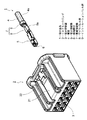
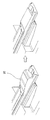
1 is an overall perspective view of a connector to which a terminal fitting according to the present invention is attached, FIG. 2 is a perspective view seen from the lower surface side of the terminal fitting shown in FIG. 1, and FIG. 3 is a portion A of the terminal fitting shown in FIG. FIG. 4 is a cross-sectional view showing an embodiment of a terminal holding force improving surface formed in the lance engaging portion of the terminal fitting shown in FIG.
図1において、端子金具1は、合成樹脂製のコネクタハウジング2の端子収容室3に収容されるようになっている。
端子金具1は、金属板のプレス成形品で、雌端子金具で構成されている。この端子金具1は、電線4の端末に接続されており、端子金具1の前部には、端子接続部5が形成されている。この端子金具1の前部に設けられている端子接続部5は、前後方向に開口する角筒状をなしており、その前端開口6を通して、雄端子(図示略)の舌片状の端子先端部が角筒状の端子嵌合部5の内部に嵌合可能に構成されている。
In FIG. 1, a
The
また、端子金具1の後部には、電線4の端末に接続する電線接続部7が設けられている。この電線接続部7は、電線4の端末にて絶縁被覆4aが皮剥ぎされることで露出された芯線4bに圧着されるワイヤバレル部8と、皮剥ぎされることで残された絶縁被覆4aの端末に加締められるインシュレーションバレル部9とからなっている。
Further, at the rear part of the
ワイヤバレル部8は、オープンバレル形式の一対の圧着片8a、8aを有しており、両圧着片8a、8aを芯線4bの左右両側から包み込むように圧着することで、芯線4bに固着されている。
インシュレーションバレル部9は、ワイヤバレル部8よりも一回り大きめに形成され、特に上下寸法がワイヤバレル部8より大きめに形成されている。このインシュレーションバレル部9は、オープンバレル形式の一対の加締片9aを有しており、絶縁被覆4aの残された部分の端末を左右両側から包み込むように加締めることで、電線4に固着されている。
The
The
また、端子金具1には、図2に示すように、端子接続部5の底面部10に、ランス係合部11と、ランス嵌入孔12と、が装備されている。
ランス係合部11は、端子接続部5の底面部10から下方に隆起した構造で構成され、コネクタハウジング2内のランス20と係合することで、抜け止めを果たすようになっている。
また、端子接続部5の底面部10に形成されるランス嵌入孔12は、ランス係合部11に係合するコネクタハウジング2の端子収容室3に設けられたランス20の外面側が没入可能な開口である。
Further, as shown in FIG. 2, the
The
The
端子接続部5のランス係合部11の上端部13からランス嵌入孔12の縁部12aの上端部にかけて、図3に示す如き端子保持力向上面14が設けられている。
この端子保持力向上面14は、端子接続部5の底面部10の面とランス嵌入孔12の先端側の端面15とによって形成される鋭角な角部を取り除きランス20に食い込むことのないなだらかな形状の面に形成されている。
A terminal holding
The terminal holding
この端子保持力向上面14は、具体的には、図4(A)に示すように、端子接続部5の底面部10の面と、ランス嵌入孔12の先端側の端面15とによって形成される鋭角な角部に微小なR面14aを形成して構成されている。
また、端子保持力向上面14は、図4(B)に示すように、端子接続部5の底面部10の面と、ランス嵌入孔12の先端側の端面15とによって形成される鋭角な角部に、所定角度で鋭角な角部を切り落とす微小な面取り14bを施して構成してもよい。
このようなR面や面取りは、ランス嵌入孔12を形成する打ち抜き工程後、打ち抜き用の金型と別途の金型で押圧して形成したり、打ち抜き工程時に形成してもよい。
Specifically, as shown in FIG. 4A, the terminal holding
Further, as shown in FIG. 4B, the terminal holding
Such R surface or chamfering may be formed by pressing with a die for punching and a separate die after the punching step for forming the
コネクタハウジング2は、図5、図6に示すように、端子金具1を保持する端子収容部3と、端子収容部3の上面に装備されたロックアーム21と、を有している。
ロックアーム21は、端子収容部3の上面(外面)に、相手側コネクタと嵌合した際にコネクタハウジング同士をロックする係止凸部22を有している。
また、端子収容部3は、端子金具1を収容する端子収容孔23と、雄端子を挿入する雄端子挿入孔24とを有している。
As shown in FIGS. 5 and 6, the
The
Moreover, the
端子収容室3の下壁25の内面には、可撓性のランス20が一体に形成されている。このランス20は、後端の固定端20aが端子収容室3の下壁25に対して結合され、前端の自由端20bが前方斜め上方に延びる片持形状となっている。
また、このランス20は、ランス20の自由端20bと端子収容室3の下壁25との間に撓みスペース26が形成されている。そして、ランス20は、可撓性を有してこのランス20の下方に設けられる撓みスペース26内で撓むように形成されている(下方に撓み、下方に撓んだ状態から上方に復元する)。
A
Further, the
そして、ランス20の自由端20bには、端子金具1のランス係合部11に係合することで、端子金具1が後方へ抜け止めするのを防止する端子係止部20cが設けられている。
また、ランス20は、ランス上面27の端子係止部20cにて端子金具1を係止する機能を有するとともに、端子係止部20cの反対側では、ランス20の下側の端子収容室3に収容される端子金具1を案内し、且つ支持する機能を有している。
The
The
このように構成されるコネクタハウジング2に端子金具1を収容するには、まず、図1に示すように、端子金具1をコネクタハウジング2の端子収容室3の端子収容孔23の後方に配置する。そして、この状態から真っ直ぐ端子収容室3の端子収容孔23の前方へ移動して図5,図6に示すように、端子収容孔23に端子金具1を挿入していく。
端子収容孔23を介して端子収容室3に挿入された端子金具1は、端子接続部5のランス係合部11がランス20の端子係止部20cに当接する。さらに端子金具1の挿入を続けると、ランス20の端子係止部20cの上方にランス20の撓みスペース26が存在することから、端子金具1は若干上方へ傾きながら前方へ移動する(あたかも斜め挿入の状態で移動する)。
このとき、端子金具1は、端子接続部5のランス係合部11がランス20の端子係止部20cの斜面を摺動してランス20を下方へ撓ませるとともに、前方へ案内される。
In order to accommodate the
In the
At this time, the
さらに端子金具1の挿入を続けると、端子金具1は、端子接続部5の前端がランス20を摺動し、これにより前方へ案内される。そして、端子金具1の傾きが元の状態に戻り、端子接続部5の前端がコネクタハウジング2の前壁28の内面に当接すると、それまで下方に撓んでいたランス20は元の状態に復元する。これにより、ランス20の端子係止部20cの係止面が端子金具1のランス係合部11に引っ掛かり、ランス20がランス嵌入孔12に装着され、端子金具1は係止される。
このようにして、端子金具1は、前部隔壁として機能するランス20と、コネクタハウジング2の上壁29とによって支持される。
When the
In this way, the
図6に示すように端子金具1をコネクタハウジング2の端子収容室3に収容して取り付けた後、自動車に装着後、修理及び/又は保全の際、端子金具1が接続されたワイヤーハーネスの端子金具を取り外す場合がある。
このような場合、ワイヤーハーネスの電線部分を持ってコネクタハウジング2の端子収容室3から引き抜くわけであるが、この場合、所定の端子保持力を有することが要求される。
また、ワイヤーハーネスの搬送工程や組付け工程で、電線に過度の負荷がかかる場合があるため、所定の端子保持力が要求される。
As shown in FIG. 6, after the
In such a case, the electric wire portion of the wire harness is held and pulled out from the
Moreover, since an excessive load may be applied to the electric wires in the wire harness conveyance process and assembly process, a predetermined terminal holding force is required.
図6に図示の端子金具1は、ランス20の端子係止部20cの係止面を端子金具1のランス係合部11に引っ掛かけて、ランス20をランス嵌入孔12に嵌合して、コネクタハウジング2の端子収容室3に収容して取り付ける。
このコネクタハウジング2の端子収容室3に端子金具1を取り付けた状態で、ワイヤーハーネスの電線部分を持ってコネクタハウジング2の端子収容室3から端子金具1を引き抜く。
The
With the
この端子接続部5のランス嵌入孔12にランス20が装着されている状態で端子保持力向上面14が形成されている端子金具1を引き抜いて、ランス20が破断して引き抜かれたときの破断荷重によって端子保持力を判断している。
すなわち、端子接続部5のランス嵌入孔12にランス20が装着されている状態で、端子金具1を引き抜く方向に荷重を掛けていくと、当初、端子保持力によって端子金具1は、引き抜かれること無く維持される。
Pull the terminal fitting 1 terminal
That is, when a load is applied in the direction in which the terminal fitting 1 is pulled out in a state where the
その後、端子金具1を引き抜く方向に荷重を上げていき、限界まで来ると、端子金具1のランス嵌入孔12の端子保持力向上面14によってランス20は、図7に示す如く破断される。
このランス20が破断されたときの破断荷重の大きさで端子保持力が測定される。
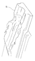
この端子金具1のランス嵌入孔12の端子保持力向上面14によって破断された状態のランス20の破断面の状態が図8に示されている。
Thereafter, the load is increased in the direction in which the terminal fitting 1 is pulled out, and when the limit is reached, the
The terminal holding force is measured by the magnitude of the breaking load when the
FIG. 8 shows a state of the fracture surface of the
本実施例に係る端子金具1について端子保持力の測定を行うと、例えば、車両で使用されるワイヤハーネス用のコネクタに要求される所定の破断荷重値を満足できる。
When the terminal holding force is measured for the
一方、図10に図示の端子金具50の端子接続部51のランス係合部53の上端部55とランス嵌入孔54の縁部54aの上端部に端子保持力向上面を形成されていない端子金具50を、ランス20の端子係止部20cの係止面を端子金具50のランス係合部53に引っ掛かけて、ランス20をランス嵌入孔54に嵌合して、コネクタハウジング2の端子収容室3に収容して取り付ける。
このコネクタハウジング2の端子収容室3に端子金具50を取り付けた状態で、ワイヤーハーネスの電線部分を持ってコネクタハウジング2の端子収容室3から端子金具50を引き抜く。
On the other hand, the terminal metal fitting in which the terminal holding force improvement surface is not formed in the
With the terminal fitting 50 attached to the
すなわち、端子金具50の端子接続部51のランス嵌入孔54にランス20が装着されている状態で、端子金具1を引き抜く方向に荷重を掛けていくと、当初、端子保持力によって端子金具50は、引き抜かれること無く維持される。
この端子金具50を引き抜いくときに、端子金具50の端子接続部51の底面部52から下方に隆起して形成されるランス係合部53の上端部55からランス嵌入孔54の縁部54aの上端部にかけて、形成されている鋭角な角部56によってランス20は、図7に示す如く破断される。
That is, when a load is applied in a direction in which the terminal fitting 1 is pulled out in a state where the
When the terminal fitting 50 is pulled out, the
この端子金具50のランス嵌入孔54の鋭角な角部56によって破断された状態のランス20の破断面の状態が図11に示されている。
この従来の端子金具50の端子接続部51の鋭角な角部56によってランス20が破断されたときの破断荷重の大きさで端子保持力が測定される。
FIG. 11 shows a state of a fracture surface of the
The terminal holding force is measured by the magnitude of the breaking load when the
従来の端子金具50について端子保持力の測定を行うと、車両で使用されるワイヤハーネス用のコネクタに要求される所定の破断荷重値を下回る場合が生じる。 When the terminal holding force of the conventional terminal fitting 50 is measured, there may be a case where it falls below a predetermined breaking load value required for a wire harness connector used in a vehicle.
この図8に示される本発明に係る端子金具1のランス係合部11の端子保持力向上面14によって破断された状態のランス20の破断面の状態を示す図と、図11に示される従来の端子金具50の端子接続部51のランス係合部53の上端部55からランス嵌入孔54の縁部54aの上端部にかけて、形成されている鋭角な角部56によって破断された状態のランス20の破断面の状態を示す図とを比較すると、図11に示される従来の端子金具50の鋭角な角部56によるランス20の破断面は、鋭い刃物で切り裂いたように破断面の表面が綺麗な面の形状となっている。
すなわち、図11に示される従来の端子金具50の鋭角な角部56によるランス20の破断面は、端子金具50の鋭角な角部56が当接した後、さほど切り裂き力を要すること無く切り裂かれていることが分かる。
The figure which shows the state of the torn surface of the
That is, the fracture surface of the
これに対し、図8に示される本発明に係る端子金具1の端子保持力向上面14によるランス20の破断面は、鋭い刃物で切り裂いたような破断面ではなく、ランス20を無理矢理破断したように、破断面の表面に凹凸が生じているのが分かる。
すなわち、図8に示される本発明に係る端子金具1の端子保持力向上面14によるランス20の破断面からは、端子金具1の端子保持力向上面14が当接した後、端子保持力向上面14でランス20を押圧し、ランス20を引き千切るように破断面の表面に凹凸が生じているが分かる。
したがって、図8に示される本発明に係る端子金具1の場合、従来の端子金具50の鋭角な角部56によってランス20を破断する破断荷重よりも大きな破断荷重で破断されていることが分かる。
On the other hand, the fracture surface of the
That is, from the fracture surface of the
Therefore, in the case of the
図10に図示の従来の端子金具のランス係合部によってランス20を破断したときの端子保持力は、車両で使用されるワイヤハーネス用のコネクタに要求される所定の破断荷重値をを下回るおそれがある。これに対し、本実施例によれば、所定の破断荷重値を充分に満たすことができる。
The terminal holding force when the
図9には、本発明に係る端子金具の別な実施例が示されている。
本実施例が図1〜図4に図示の実施例と異なる点は、本発明に係る端子金具が雄端子金具によって構成されている点である。
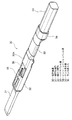
FIG. 9 shows another embodiment of the terminal fitting according to the present invention.
This embodiment differs from the embodiment shown in FIGS. 1 to 4 in that the terminal fitting according to the present invention is constituted by a male terminal fitting.
図9において、端子金具30は、金属板のプレス成形品で、舌片状の端子先端部31と、端子先端部31の基端に連なる角筒状の端子中間部32と、電線40の芯線を圧着するワイヤバレル部33と、電線40の被覆部の上に加締め付けられて電線40を固定するインシュレーションバレル部34と、を備えている。
また、端子中間部32の底面部32aは、雌端子金具で構成される端子金具1の端子接続部5の底面部10と同様の構造で、ランス係合部35と、ランス嵌入孔36と、が装備されている。
In FIG. 9, the terminal fitting 30 is a press-formed product of a metal plate, and is a tongue-shaped
Further, the
ランス係合部35は、端子中間部32の底面部32aから下方に隆起した構造で構成され、コネクタハウジング内のランスと係合することで、抜け止めを果たすようになっている。
また、端子中間部32の底面部32aに形成されるランス嵌入孔36は、ランス係合部35に係合するコネクタハウジングの端子収容室に設けられたランスの外面側が没入可能な開口となっている。
The
The
端子中間部32のランス係合部35の上端部には、図3に図示されるのと同じような、端子保持力向上面が設けられている。この端子保持力向上面は、端子中間部32の底面部32aに形成されるランス嵌入孔36を形成する孔端面とによって形成される鋭角な角部に形成されている。
この端子保持力向上面は、図4(A)に示すように、ランス嵌入孔36を形成する孔端面とによって形成されるランス係合部35の上端部に微小なR面を形成して構成してある。
また、端子中間部32のランス係合部35の端子保持力向上面は、図4(B)に示すように、ランス嵌入孔36を形成する孔端面とによって形成されるランス係合部35の上端部に、微小な面取りをして構成してもよい。
A terminal holding force improving surface similar to that shown in FIG. 3 is provided at the upper end of the
As shown in FIG. 4A, the terminal holding force improving surface is formed by forming a minute R surface at the upper end portion of the
Further, as shown in FIG. 4B, the terminal holding force improving surface of the
この他、本発明は本発明の主旨を変えない範囲で種々変更実施可能なことは勿論である。 In addition, the present invention can of course be modified in various ways within the scope not changing the gist of the present invention.
1……………………端子金具
2……………………コネクタハウジング
3……………………端子収容室
4……………………電線
5……………………端子接続部
6……………………前端開口
7……………………電線接続部
8……………………ワイヤバレル部
9……………………インシュレーションバレル部
10…………………底面部
11…………………ランス係合部
12…………………ランス嵌入孔
13…………………上端部
14…………………端子保持力向上面
14a………………微小なR面
14b………………微小な面取り
15…………………孔端面
20…………………ランス
20b………………自由端
30…………………端子金具
31…………………端子先端部
32…………………端子中間部
33…………………ワイヤバレル部
34…………………インシュレーションバレル部
35…………………ランス係合部
36…………………ランス嵌入孔
1 ……………………
Claims (4)
前記端子金具のランス係合部と前記ランスの自由端との係止当接面を設け、
前記係止当接面は、この上端部に、前記端子金具の端子接続部の底面部の面とランス嵌入孔の先端側の端面とによって形成される鋭角な角部を取り除いてなる端子保持力向上面を設けたことを特徴とする端子金具。 A terminal fitting that is inserted into the terminal accommodating chamber of a connector having a lance that is elastically deformable with a base end supported in a cantilever manner in the terminal accommodating chamber, and is locked to the free end of the lance,
Provide a locking contact surface between the lance engaging portion of the terminal fitting and the free end of the lance ,
The locking contact surface has a terminal holding force formed by removing an acute corner formed by the surface of the bottom surface of the terminal connection portion of the terminal fitting and the end surface of the distal end side of the lance insertion hole at the upper end portion. A terminal fitting characterized by an improved surface.
前記端子保持力向上面は、前記ランス係合部の上端部に形成する微小なR面であることを特徴とする端子金具。 In the terminal fitting according to claim 1,
The terminal holding force improving surface is a minute R surface formed on an upper end portion of the lance engaging portion.
前記端子保持力向上面は、前記ランス係合部の上端部に形成する微小な面取りであることを特徴とする端子金具。 In the terminal fitting according to claim 1,
The terminal holding force improving surface is a minute chamfer formed on an upper end portion of the lance engaging portion.
前記端子金具のランス嵌入孔の打ち抜き形成によって前記端子金具のランス係合部と前記ランスの自由端との係止当接面を形成する工程と、 Forming a locking contact surface between the lance engaging portion of the terminal fitting and the free end of the lance by punching the lance insertion hole of the terminal fitting;
前記ランス嵌入孔の打ち抜き時又は該打ち抜き後に、前記端子金具の端子接続部の底面部の面と前記ランス嵌入孔の先端側の端面とによって形成される鋭角な角部を打ち抜き用の金型と別途の金型で押圧して前記角部にR面を形成する又は面取りを施して端子保持力向上面を設ける工程と、 At the time of punching the lance insertion hole or after the punching, a die for punching a sharp corner formed by the surface of the bottom surface portion of the terminal connection portion of the terminal fitting and the end surface on the tip side of the lance insertion hole, A step of forming an R surface at the corner by pressing with a separate mold or chamfering to provide a terminal holding force improving surface;
を含むことを特徴とする端子金具の製造方法。 The manufacturing method of the terminal metal fitting characterized by including.
Priority Applications (2)
| Application Number | Priority Date | Filing Date | Title |
|---|---|---|---|
| JP2014234400A JP6141817B2 (en) | 2014-11-19 | 2014-11-19 | Terminal fitting and method of manufacturing terminal fitting |
| CN201510802075.6A CN105609980B (en) | 2014-11-19 | 2015-11-19 | Terminal metal piece |
Applications Claiming Priority (1)
| Application Number | Priority Date | Filing Date | Title |
|---|---|---|---|
| JP2014234400A JP6141817B2 (en) | 2014-11-19 | 2014-11-19 | Terminal fitting and method of manufacturing terminal fitting |
Publications (2)
| Publication Number | Publication Date |
|---|---|
| JP2016100109A JP2016100109A (en) | 2016-05-30 |
| JP6141817B2 true JP6141817B2 (en) | 2017-06-07 |
Family
ID=55989640
Family Applications (1)
| Application Number | Title | Priority Date | Filing Date |
|---|---|---|---|
| JP2014234400A Active JP6141817B2 (en) | 2014-11-19 | 2014-11-19 | Terminal fitting and method of manufacturing terminal fitting |
Country Status (2)
| Country | Link |
|---|---|
| JP (1) | JP6141817B2 (en) |
| CN (1) | CN105609980B (en) |
Families Citing this family (1)
| Publication number | Priority date | Publication date | Assignee | Title |
|---|---|---|---|---|
| JP2022068979A (en) * | 2020-10-23 | 2022-05-11 | 住友電装株式会社 | connector |
Family Cites Families (12)
| Publication number | Priority date | Publication date | Assignee | Title |
|---|---|---|---|---|
| US4797116A (en) * | 1987-01-26 | 1989-01-10 | Amp Incorporated | Electrical connector having a movable contact guide and lance-maintaining member |
| JPH0355674U (en) * | 1989-10-03 | 1991-05-29 | ||
| FR2684242B1 (en) * | 1991-11-22 | 1995-11-17 | Amp France | ELECTRICAL CONNECTOR ASSEMBLY COMPRISING A TERMINAL LOCKING ELEMENT. |
| US6000976A (en) * | 1993-11-30 | 1999-12-14 | Yazaki Corporation | Terminal for passing through waterproof rubber plug and method of producing terminal |
| JP3007781B2 (en) * | 1993-11-30 | 2000-02-07 | 矢崎総業株式会社 | Waterproof rubber plug insertion terminal |
| JP3558037B2 (en) * | 2000-12-21 | 2004-08-25 | 住友電装株式会社 | Terminal fitting |
| US6817900B2 (en) * | 2001-07-31 | 2004-11-16 | Yazaki Corporation | Electrical connector having terminal locking structure |
| JP3415140B1 (en) * | 2002-07-04 | 2003-06-09 | 住友電装株式会社 | connector |
| JP4214889B2 (en) * | 2003-10-30 | 2009-01-28 | 住友電装株式会社 | connector |
| JP4941740B2 (en) * | 2007-06-04 | 2012-05-30 | 住友電装株式会社 | connector |
| JP5594219B2 (en) * | 2010-10-21 | 2014-09-24 | 住友電装株式会社 | Locking structure between metal lance and resin parts |
| JP5682061B2 (en) * | 2010-12-21 | 2015-03-11 | 矢崎総業株式会社 | connector |
-
2014
- 2014-11-19 JP JP2014234400A patent/JP6141817B2/en active Active
-
2015
- 2015-11-19 CN CN201510802075.6A patent/CN105609980B/en active Active
Also Published As
| Publication number | Publication date |
|---|---|
| CN105609980A (en) | 2016-05-25 |
| JP2016100109A (en) | 2016-05-30 |
| CN105609980B (en) | 2019-05-10 |
Similar Documents
| Publication | Publication Date | Title |
|---|---|---|
| JP4743109B2 (en) | Terminal fittings and connectors | |
| EP2852004B1 (en) | Terminal fitting | |
| EP1923962B1 (en) | A connector and method of preassembling it | |
| JP4007279B2 (en) | Female terminal bracket | |
| WO2012029352A1 (en) | Terminal fitting with cable | |
| JP4555223B2 (en) | Connecting terminal | |
| JP3763574B2 (en) | connector | |
| JP2010049896A (en) | Connector | |
| JP4457917B2 (en) | connector | |
| KR101221769B1 (en) | Terminal fitting and production method therefor | |
| EP2445057A1 (en) | Terminal fitting | |
| JP2004039498A (en) | Connector | |
| JP5454486B2 (en) | Lock structure | |
| JP2009517822A (en) | Electrical terminal with guide means | |
| JP2004362973A (en) | Terminal fitting | |
| JP6141817B2 (en) | Terminal fitting and method of manufacturing terminal fitting | |
| JP2010049844A (en) | Connector and terminal metal fitting | |
| JP4321417B2 (en) | Terminal fittings and connectors | |
| JP2012109031A (en) | Connector | |
| JP2010129358A (en) | Connector and female terminal fitting | |
| JP2007194047A (en) | Terminal fitting | |
| EP2164132A1 (en) | A terminal fitting, a connector, and assembling method therefor | |
| JP7144290B2 (en) | Terminal connection structure | |
| JP2005158418A (en) | Connector | |
| JP2011018522A (en) | Connector |
Legal Events
| Date | Code | Title | Description |
|---|---|---|---|
| A977 | Report on retrieval |
Free format text: JAPANESE INTERMEDIATE CODE: A971007 Effective date: 20161025 |
|
| A131 | Notification of reasons for refusal |
Free format text: JAPANESE INTERMEDIATE CODE: A131 Effective date: 20161101 |
|
| A521 | Request for written amendment filed |
Free format text: JAPANESE INTERMEDIATE CODE: A523 Effective date: 20161216 |
|
| TRDD | Decision of grant or rejection written | ||
| A01 | Written decision to grant a patent or to grant a registration (utility model) |
Free format text: JAPANESE INTERMEDIATE CODE: A01 Effective date: 20170425 |
|
| A61 | First payment of annual fees (during grant procedure) |
Free format text: JAPANESE INTERMEDIATE CODE: A61 Effective date: 20170508 |
|
| R150 | Certificate of patent or registration of utility model |
Ref document number: 6141817 Country of ref document: JP Free format text: JAPANESE INTERMEDIATE CODE: R150 |
|
| R250 | Receipt of annual fees |
Free format text: JAPANESE INTERMEDIATE CODE: R250 |
|
| R250 | Receipt of annual fees |
Free format text: JAPANESE INTERMEDIATE CODE: R250 |
|
| R250 | Receipt of annual fees |
Free format text: JAPANESE INTERMEDIATE CODE: R250 |
|
| R250 | Receipt of annual fees |
Free format text: JAPANESE INTERMEDIATE CODE: R250 |
|
| S531 | Written request for registration of change of domicile |
Free format text: JAPANESE INTERMEDIATE CODE: R313531 |
|
| R350 | Written notification of registration of transfer |
Free format text: JAPANESE INTERMEDIATE CODE: R350 |