JP6139545B2 - Friction stir welding tool made of carbide tungsten carbide containing nickel and having an AL203 surface coating - Google Patents
Friction stir welding tool made of carbide tungsten carbide containing nickel and having an AL203 surface coating Download PDFInfo
- Publication number
- JP6139545B2 JP6139545B2 JP2014540355A JP2014540355A JP6139545B2 JP 6139545 B2 JP6139545 B2 JP 6139545B2 JP 2014540355 A JP2014540355 A JP 2014540355A JP 2014540355 A JP2014540355 A JP 2014540355A JP 6139545 B2 JP6139545 B2 JP 6139545B2
- Authority
- JP
- Japan
- Prior art keywords
- stir welding
- friction stir
- surface coating
- welding tool
- cemented carbide
- Prior art date
- Legal status (The legal status is an assumption and is not a legal conclusion. Google has not performed a legal analysis and makes no representation as to the accuracy of the status listed.)
- Expired - Fee Related
Links
- 238000003466 welding Methods 0.000 title claims description 81
- 238000003756 stirring Methods 0.000 title claims description 65
- 238000000576 coating method Methods 0.000 title claims description 49
- 239000011248 coating agent Substances 0.000 title claims description 48
- 229910052759 nickel Inorganic materials 0.000 title description 11
- PXHVJJICTQNCMI-UHFFFAOYSA-N Nickel Chemical compound [Ni] PXHVJJICTQNCMI-UHFFFAOYSA-N 0.000 title 2
- UONOETXJSWQNOL-UHFFFAOYSA-N tungsten carbide Chemical compound [W+]#[C-] UONOETXJSWQNOL-UHFFFAOYSA-N 0.000 title 1
- 239000000523 sample Substances 0.000 claims description 55
- 239000002245 particle Substances 0.000 claims description 24
- 238000000034 method Methods 0.000 claims description 23
- 229910018072 Al 2 O 3 Inorganic materials 0.000 claims description 20
- 230000008569 process Effects 0.000 claims description 16
- 239000011230 binding agent Substances 0.000 claims description 13
- ATJFFYVFTNAWJD-UHFFFAOYSA-N Tin Chemical compound [Sn] ATJFFYVFTNAWJD-UHFFFAOYSA-N 0.000 claims description 9
- 239000000463 material Substances 0.000 claims description 8
- 150000001875 compounds Chemical class 0.000 claims description 4
- 150000004767 nitrides Chemical class 0.000 claims description 4
- 238000012360 testing method Methods 0.000 description 28
- 230000003647 oxidation Effects 0.000 description 19
- 238000007254 oxidation reaction Methods 0.000 description 19
- 239000012071 phase Substances 0.000 description 17
- 229910000831 Steel Inorganic materials 0.000 description 12
- 239000010959 steel Substances 0.000 description 12
- 229910001209 Low-carbon steel Inorganic materials 0.000 description 9
- 229910052782 aluminium Inorganic materials 0.000 description 7
- 238000005229 chemical vapour deposition Methods 0.000 description 7
- 229910052802 copper Inorganic materials 0.000 description 5
- 239000010949 copper Substances 0.000 description 5
- 238000005266 casting Methods 0.000 description 4
- 229910052804 chromium Inorganic materials 0.000 description 4
- 239000007769 metal material Substances 0.000 description 4
- 239000000203 mixture Substances 0.000 description 4
- 238000005245 sintering Methods 0.000 description 4
- 239000000126 substance Substances 0.000 description 4
- 238000004441 surface measurement Methods 0.000 description 4
- 229910045601 alloy Inorganic materials 0.000 description 3
- 239000000956 alloy Substances 0.000 description 3
- XAGFODPZIPBFFR-UHFFFAOYSA-N aluminium Chemical compound [Al] XAGFODPZIPBFFR-UHFFFAOYSA-N 0.000 description 3
- 230000008901 benefit Effects 0.000 description 3
- 229910000851 Alloy steel Inorganic materials 0.000 description 2
- 229910001369 Brass Inorganic materials 0.000 description 2
- 229910000906 Bronze Inorganic materials 0.000 description 2
- 239000010951 brass Substances 0.000 description 2
- 239000010974 bronze Substances 0.000 description 2
- KUNSUQLRTQLHQQ-UHFFFAOYSA-N copper tin Chemical compound [Cu].[Sn] KUNSUQLRTQLHQQ-UHFFFAOYSA-N 0.000 description 2
- 229910052742 iron Inorganic materials 0.000 description 2
- 238000005304 joining Methods 0.000 description 2
- 229910052751 metal Inorganic materials 0.000 description 2
- 239000002184 metal Substances 0.000 description 2
- 238000005240 physical vapour deposition Methods 0.000 description 2
- OKTJSMMVPCPJKN-UHFFFAOYSA-N Carbon Chemical compound [C] OKTJSMMVPCPJKN-UHFFFAOYSA-N 0.000 description 1
- RYGMFSIKBFXOCR-UHFFFAOYSA-N Copper Chemical compound [Cu] RYGMFSIKBFXOCR-UHFFFAOYSA-N 0.000 description 1
- 229910010037 TiAlN Inorganic materials 0.000 description 1
- -1 TiCN Chemical compound 0.000 description 1
- 229910009043 WC-Co Inorganic materials 0.000 description 1
- 230000009286 beneficial effect Effects 0.000 description 1
- 229910052799 carbon Inorganic materials 0.000 description 1
- 230000008859 change Effects 0.000 description 1
- 239000011362 coarse particle Substances 0.000 description 1
- 238000005261 decarburization Methods 0.000 description 1
- 230000007423 decrease Effects 0.000 description 1
- 230000001419 dependent effect Effects 0.000 description 1
- 238000009792 diffusion process Methods 0.000 description 1
- 238000004090 dissolution Methods 0.000 description 1
- 230000004927 fusion Effects 0.000 description 1
- 238000000227 grinding Methods 0.000 description 1
- 238000009413 insulation Methods 0.000 description 1
- 238000004519 manufacturing process Methods 0.000 description 1
- 230000008018 melting Effects 0.000 description 1
- 238000002844 melting Methods 0.000 description 1
- 150000001247 metal acetylides Chemical class 0.000 description 1
- 238000012986 modification Methods 0.000 description 1
- 230000004048 modification Effects 0.000 description 1
- 239000012768 molten material Substances 0.000 description 1
- 229910052758 niobium Inorganic materials 0.000 description 1
- 238000005498 polishing Methods 0.000 description 1
- 239000011148 porous material Substances 0.000 description 1
- 230000001681 protective effect Effects 0.000 description 1
- 238000007712 rapid solidification Methods 0.000 description 1
- 230000035939 shock Effects 0.000 description 1
- 239000007790 solid phase Substances 0.000 description 1
- 238000001694 spray drying Methods 0.000 description 1
- 229910052715 tantalum Inorganic materials 0.000 description 1
- 238000005050 thermomechanical fatigue Methods 0.000 description 1
- 229910052719 titanium Inorganic materials 0.000 description 1
- 230000009466 transformation Effects 0.000 description 1
Images

Classifications
-
- B—PERFORMING OPERATIONS; TRANSPORTING
- B23—MACHINE TOOLS; METAL-WORKING NOT OTHERWISE PROVIDED FOR
- B23K—SOLDERING OR UNSOLDERING; WELDING; CLADDING OR PLATING BY SOLDERING OR WELDING; CUTTING BY APPLYING HEAT LOCALLY, e.g. FLAME CUTTING; WORKING BY LASER BEAM
- B23K20/00—Non-electric welding by applying impact or other pressure, with or without the application of heat, e.g. cladding or plating
- B23K20/12—Non-electric welding by applying impact or other pressure, with or without the application of heat, e.g. cladding or plating the heat being generated by friction; Friction welding
- B23K20/122—Non-electric welding by applying impact or other pressure, with or without the application of heat, e.g. cladding or plating the heat being generated by friction; Friction welding using a non-consumable tool, e.g. friction stir welding
- B23K20/1245—Non-electric welding by applying impact or other pressure, with or without the application of heat, e.g. cladding or plating the heat being generated by friction; Friction welding using a non-consumable tool, e.g. friction stir welding characterised by the apparatus
- B23K20/1255—Tools therefor, e.g. characterised by the shape of the probe
-
- B—PERFORMING OPERATIONS; TRANSPORTING
- B23—MACHINE TOOLS; METAL-WORKING NOT OTHERWISE PROVIDED FOR
- B23K—SOLDERING OR UNSOLDERING; WELDING; CLADDING OR PLATING BY SOLDERING OR WELDING; CUTTING BY APPLYING HEAT LOCALLY, e.g. FLAME CUTTING; WORKING BY LASER BEAM
- B23K20/00—Non-electric welding by applying impact or other pressure, with or without the application of heat, e.g. cladding or plating
- B23K20/14—Preventing or minimising gas access, or using protective gases or vacuum during welding
-
- C—CHEMISTRY; METALLURGY
- C22—METALLURGY; FERROUS OR NON-FERROUS ALLOYS; TREATMENT OF ALLOYS OR NON-FERROUS METALS
- C22C—ALLOYS
- C22C29/00—Alloys based on carbides, oxides, nitrides, borides, or silicides, e.g. cermets, or other metal compounds, e.g. oxynitrides, sulfides
- C22C29/02—Alloys based on carbides, oxides, nitrides, borides, or silicides, e.g. cermets, or other metal compounds, e.g. oxynitrides, sulfides based on carbides or carbonitrides
- C22C29/06—Alloys based on carbides, oxides, nitrides, borides, or silicides, e.g. cermets, or other metal compounds, e.g. oxynitrides, sulfides based on carbides or carbonitrides based on carbides, but not containing other metal compounds
- C22C29/08—Alloys based on carbides, oxides, nitrides, borides, or silicides, e.g. cermets, or other metal compounds, e.g. oxynitrides, sulfides based on carbides or carbonitrides based on carbides, but not containing other metal compounds based on tungsten carbide
-
- C—CHEMISTRY; METALLURGY
- C23—COATING METALLIC MATERIAL; COATING MATERIAL WITH METALLIC MATERIAL; CHEMICAL SURFACE TREATMENT; DIFFUSION TREATMENT OF METALLIC MATERIAL; COATING BY VACUUM EVAPORATION, BY SPUTTERING, BY ION IMPLANTATION OR BY CHEMICAL VAPOUR DEPOSITION, IN GENERAL; INHIBITING CORROSION OF METALLIC MATERIAL OR INCRUSTATION IN GENERAL
- C23C—COATING METALLIC MATERIAL; COATING MATERIAL WITH METALLIC MATERIAL; SURFACE TREATMENT OF METALLIC MATERIAL BY DIFFUSION INTO THE SURFACE, BY CHEMICAL CONVERSION OR SUBSTITUTION; COATING BY VACUUM EVAPORATION, BY SPUTTERING, BY ION IMPLANTATION OR BY CHEMICAL VAPOUR DEPOSITION, IN GENERAL
- C23C16/00—Chemical coating by decomposition of gaseous compounds, without leaving reaction products of surface material in the coating, i.e. chemical vapour deposition [CVD] processes
- C23C16/22—Chemical coating by decomposition of gaseous compounds, without leaving reaction products of surface material in the coating, i.e. chemical vapour deposition [CVD] processes characterised by the deposition of inorganic material, other than metallic material
- C23C16/30—Deposition of compounds, mixtures or solid solutions, e.g. borides, carbides, nitrides
- C23C16/40—Oxides
- C23C16/403—Oxides of aluminium, magnesium or beryllium
-
- B—PERFORMING OPERATIONS; TRANSPORTING
- B23—MACHINE TOOLS; METAL-WORKING NOT OTHERWISE PROVIDED FOR
- B23K—SOLDERING OR UNSOLDERING; WELDING; CLADDING OR PLATING BY SOLDERING OR WELDING; CUTTING BY APPLYING HEAT LOCALLY, e.g. FLAME CUTTING; WORKING BY LASER BEAM
- B23K2101/00—Articles made by soldering, welding or cutting
- B23K2101/18—Sheet panels
-
- B—PERFORMING OPERATIONS; TRANSPORTING
- B23—MACHINE TOOLS; METAL-WORKING NOT OTHERWISE PROVIDED FOR
- B23K—SOLDERING OR UNSOLDERING; WELDING; CLADDING OR PLATING BY SOLDERING OR WELDING; CUTTING BY APPLYING HEAT LOCALLY, e.g. FLAME CUTTING; WORKING BY LASER BEAM
- B23K2103/00—Materials to be soldered, welded or cut
- B23K2103/02—Iron or ferrous alloys
- B23K2103/04—Steel or steel alloys
Landscapes
- Chemical & Material Sciences (AREA)
- Engineering & Computer Science (AREA)
- Mechanical Engineering (AREA)
- Materials Engineering (AREA)
- Metallurgy (AREA)
- Organic Chemistry (AREA)
- Inorganic Chemistry (AREA)
- General Chemical & Material Sciences (AREA)
- Chemical Kinetics & Catalysis (AREA)
- Pressure Welding/Diffusion-Bonding (AREA)
- Other Surface Treatments For Metallic Materials (AREA)
Description
本発明は、金属板、特に鋼板の溶接用の摩擦撹拌接合工具に関する。 The present invention relates to a friction stir welding tool for welding metal plates, particularly steel plates.
摩擦撹拌接合は、産業界において、特にアルミニウム、真鍮、青銅などの金属材料の溶接において長年にわたって使用されている。これは、回転かつ移動する摩擦撹拌接合プローブを溶接される接合部に沿って強制的に移動させることによって生ずる摩擦熱による局所的塑性変形を伴う固相プロセスである。接合部におけるプローブと金属材料の接触による摩擦熱はその金属材料を撹拌可能にし、接合部に沿ったプローブの回転及び移動が撹拌された材料の溶接部を生じさせる。 Friction stir welding has been used in the industry for many years, especially in the welding of metallic materials such as aluminum, brass, bronze. This is a solid phase process with local plastic deformation due to frictional heat caused by forcibly moving a rotating and moving friction stir welding probe along the welded joint. Frictional heat due to contact between the probe and the metal material at the joint allows the metal material to be agitated, and rotation and movement of the probe along the joint results in a weld of the agitated material.
摩擦撹拌接合は、溶融材料の急速な凝固を伴う旧来のレーザー溶接や融接と比べて大きな経済的利益を生む可能性を有する技術である。摩擦撹拌接合を用いる利点は、限定された領域が加熱されること、またその結果としての溶接部が十分に平滑であることが多く、後続の研磨のステップをなくすことである。 Friction stir welding is a technique that has the potential to generate significant economic benefits compared to traditional laser welding and fusion with rapid solidification of molten material. The advantage of using friction stir welding is that a limited area is heated and the resulting weld is often smooth enough to eliminate subsequent polishing steps.
鋼の摩擦撹拌接合は、旧来のアーク溶接やレーザービーム溶接と比べて気孔のより少ない、炭素拡散のより少ない、かつより強度の大きい溶接部を生じさせることができる。 Friction stir welding of steel can produce welds with fewer pores, less carbon diffusion, and greater strength than conventional arc welding or laser beam welding.
鋼の溶接工程中の摩擦撹拌接合プローブの条件は、きわめて要求が厳しい。摩擦撹拌接合は、高温での熱的繰返しを伴う。溶接部の温度は多分約800〜1000℃であり、プローブの機械的強度はこの高温において高くなければならない。高温における機械的強度が不十分な場合、プローブは酸化、摩耗、及び圧壊又は破断を受けることになる。 The conditions of the friction stir welding probe during the steel welding process are extremely demanding. Friction stir welding involves thermal repetition at high temperatures. The temperature of the weld is probably about 800-1000 ° C., and the mechanical strength of the probe must be high at this high temperature. If the mechanical strength at high temperatures is insufficient, the probe will undergo oxidation, wear, and crushing or breaking.
米国特許出願公開第2010/0258612号明細書には、1枚又は複数枚の層で部分的にコーティングされた硬質合金から作られる鋼を溶接するための摩擦撹拌接合工具が開示されている。 US 2010/0258612 discloses a friction stir welding tool for welding steel made from hard alloys partially coated with one or more layers.
摩擦撹拌接合工具の分野にはさらなる改良の必要性が存在する。摩擦撹拌接合工具は、あまりにも高価であってはならず、長く予測可能な寿命を有し、かつ高温での高強度及び耐摩耗性を含むべきである。 There is a need for further improvements in the field of friction stir welding tools. Friction stir welding tools should not be too expensive, should have a long and predictable life, and should include high strength and wear resistance at high temperatures.
本発明の目的は、既知の摩擦撹拌接合工具と比較して改良された特性を有する摩擦撹拌接合工具を提供することである。 The object of the present invention is to provide a friction stir welding tool having improved properties compared to known friction stir welding tools.
本発明のさらなる目的は、高い耐摩耗性及び高い耐酸化性を有する摩擦撹拌接合工具を提供することである。 A further object of the present invention is to provide a friction stir welding tool having high wear resistance and high oxidation resistance.
本発明は、独立請求項に従って、摩擦撹拌接合工具、このような工具の製造方法、及びこのような工具の使用を開示する。さらなる実施形態は従属請求項において開示される。 The present invention discloses, according to the independent claims, a friction stir welding tool, a method of manufacturing such a tool, and the use of such a tool. Further embodiments are disclosed in the dependent claims.
本発明による摩擦撹拌接合工具は、バインダー相中にWC粒子を含む超硬合金から作られ、上記超硬合金は3wt%〜10wt%のNiを含み、かつその接合工具はAl2O3を含む表面コーティングで少なくとも部分的にコーティングされる。 The friction stir welding tool according to the present invention is made of a cemented carbide containing WC particles in the binder phase, the cemented carbide containing 3 wt% to 10 wt% Ni, and the joining tool contains Al 2 O 3 . It is at least partially coated with a surface coating.
一実施形態では摩擦撹拌接合工具は、バインダー相中にWC粒子を含む超硬合金から作られ、上記超硬合金は3wt%〜10wt%のNiを含み、かつこの接合工具は表面コーティングで少なくとも部分的にコーティングされる。表面コーティングは、Ti炭化物層、Ti窒化物層、Ti炭窒化物層、Tiオキシ炭化物層、Tiオキシ炭窒化物層、Zr炭化物層、Zr窒化物層、Zr炭窒化物層、Zrオキシ炭化物層、及びZrオキシ炭窒化物層のうちの少なくとも1層を含むTi化合物及びZr化合物のうちの少なくとも1種類から作られる内層である第1の表面コーティングと、Al2O3を含む外層である第2の表面コーティングとを少なくとも含む。 In one embodiment, the friction stir welding tool is made from a cemented carbide containing WC particles in the binder phase, the cemented carbide comprising 3 wt% to 10 wt% Ni, and the joining tool is at least partially coated with a surface coating. Coated. Surface coating is Ti carbide layer, Ti nitride layer, Ti carbonitride layer, Ti oxycarbide layer, Ti oxycarbonitride layer, Zr carbide layer, Zr nitride layer, Zr carbonitride layer, Zr oxycarbide layer And a first surface coating that is an inner layer made of at least one of a Ti compound and a Zr compound including at least one of Zr oxycarbonitride layers, and an outer layer including Al 2 O 3 . 2 surface coatings.
本発明による摩擦撹拌接合工具は、高い高温硬さ及び高い機械的強度を有し、かつ耐熱機械疲労性である。 The friction stir welding tool according to the present invention has high high-temperature hardness and high mechanical strength, and is heat-resistant mechanical fatigue.
この溶接は、可塑変形可能な材料、例えばアルミニウム、銅、真鍮、青銅、鋼、及び他の金属材料及び合金において行うことができる。具体的には本発明の摩擦撹拌接合工具は、鋼と鋼、鋼とアルミニウムの溶接を可能にし、そのために工具はきわめて高い温度にさらされる。 This welding can be performed on plastically deformable materials such as aluminum, copper, brass, bronze, steel, and other metallic materials and alloys. In particular, the friction stir welding tool of the present invention enables welding of steel to steel, steel to aluminum, and therefore the tool is exposed to very high temperatures.
本発明による摩擦撹拌接合工具は、任意の望ましい形状のものであることができる。プローブは、例えば条溝を有する平頭のスクリューの形状であることもでき、またその用途のための任意の他の適切な仕様を含むこともできる。 The friction stir welding tool according to the present invention can be of any desired shape. The probe can be, for example, in the form of a flat head screw with grooves, and can include any other suitable specification for that application.
超硬合金は、一般にバインダー相中にWC粒子を含む材料である。超硬合金は、微粉砕、噴霧乾燥、加圧成形、及び焼結を含む工程で作り出すことができる。時には超硬合金中のWC粒子はα相と呼ばれる。WC粒子のサイズは、一般に焼結工程の間に変化している。本文書中で意味する粒子サイズは、焼結後のWC粒子の粒子サイズである。WC粒子サイズは、Jeffriesの測面法(ASTM E112)により測定され、これは既知の面積内の粒子の数を数えることに基づく方法である。 Cemented carbide is generally a material containing WC particles in the binder phase. Cemented carbides can be produced by processes including fine grinding, spray drying, pressure forming, and sintering. Sometimes the WC particles in the cemented carbide are called α phase. The size of the WC particles generally changes during the sintering process. The particle size meant in this document is the particle size of the WC particles after sintering. The WC particle size is measured by Jeffries' surface measurement method (ASTM E112), which is based on counting the number of particles in a known area.
典型的な超硬合金中のバインダー相は、WC粒子を取り巻く金属相と、存在し得る他の硬質相、例えばTiN、TiC、又はTiCNのような硬質相である。バインダー相中のNi内容物は、それが超硬合金の高い耐熱機械疲労性に貢献するので有利である。Ni内容物はまた、超硬合金の高い耐酸化性を生じさせる。本発明の摩擦撹拌接合工具における超硬合金は、Niを3〜10wt%、好ましくはNiを4〜5wt%含む。 The binder phase in a typical cemented carbide is a metal phase surrounding the WC particles and other hard phases that may be present, such as TiN, TiC, or TiCN. The Ni content in the binder phase is advantageous because it contributes to the high heat-resistant mechanical fatigue of the cemented carbide. The Ni content also gives rise to the high oxidation resistance of the cemented carbide. The cemented carbide in the friction stir welding tool of the present invention contains 3 to 10 wt% Ni, preferably 4 to 5 wt% Ni.
表面コーティングは、超硬合金の高い耐酸化性に貢献する。本発明の第2の表面コーティングは、好ましくはAl2O3からなり、より好ましくはα−Al2O3からなり、最も好ましくは微細粒α−Al2O3からなる。 The surface coating contributes to the high oxidation resistance of the cemented carbide. The second surface coating of the present invention preferably consists of Al 2 O 3 , more preferably α-Al 2 O 3 , most preferably fine-grained α-Al 2 O 3 .
本発明の表面コーティングは、工具の外面全体を覆うように、又は工具の外面の一部分のみに、好ましくは溶接工程の間に摩耗に曝される部分に塗布することができる。表面コーティングは、例えば化学蒸着(CVD)又は物理蒸着(PVD)技術により塗布することができる。 The surface coating of the present invention can be applied to cover the entire outer surface of the tool, or to only a portion of the outer surface of the tool, preferably on the portion that is subject to wear during the welding process. The surface coating can be applied, for example, by chemical vapor deposition (CVD) or physical vapor deposition (PVD) techniques.
本発明の一実施形態では溶接工具の外面は、上記表面コーティングで完全にコーティングされる。全体的にコーティングされる摩擦撹拌接合工具は高い耐酸化性を示すので、完全にコーティングされた工具が有利である。 In one embodiment of the invention, the outer surface of the welding tool is completely coated with the above surface coating. A fully coated tool is advantageous because friction stir welding tools that are totally coated exhibit high oxidation resistance.
本発明の一実施形態では表面コーティングはCVD技術を用いて塗布される。これは、工具の外面全体を同時にコーティングすることができ、かつ高い圧縮応力に関係する問題なしに比較的厚いコーティングを塗布することができるので有利である。 In one embodiment of the invention, the surface coating is applied using CVD techniques. This is advantageous because the entire outer surface of the tool can be coated simultaneously and a relatively thick coating can be applied without the problems associated with high compressive stresses.
本発明の一実施形態では上記表面コーティングは、最も外側のAl2O3の第2の表面コーティングと、中間表面コーティングすなわち内層である第1の表面コーティングとを含み、中間表面コーティングは、超硬合金がAl2O3の上記第2の表面コーティングと直接に接しないように塗布される。中間表面コーティングの厚さは好ましくは0.3μmを超え、6μm未満である。 In one embodiment of the invention, the surface coating comprises a second outermost Al 2 O 3 surface coating and an intermediate surface coating or first surface coating that is an inner layer, The alloy is applied such that it does not directly contact the second surface coating of Al 2 O 3 . The thickness of the intermediate surface coating is preferably greater than 0.3 μm and less than 6 μm.
一実施形態では中間コーティングは、Al2O3のCVD工程の間にα−Al2O3の成長を促進させること、及び上記CVD工程の間にκ−Al2O3が成長するのを防止することを目的とする。中間コーティングは、例えばTiN、TiCN、ZrC、TiC、又はこれらの混合物であることができる。 Intermediate coating in one embodiment, preventing possible to promote the growth of α-Al 2 O 3 between Al 2 O 3 of CVD processes, and κ-Al 2 O 3 during the CVD process from growing The purpose is to do. The intermediate coating can be, for example, TiN, TiCN, ZrC, TiC, or a mixture thereof.
本発明の一実施形態ではAl2O3を含む第2の表面コーティングは、5μmを超える、好ましくは少なくとも6μmの平均厚さを有する。平均厚さは、好ましくは30μm未満、またより好ましくは20μm未満である。この厚さは、それが耐摩耗性を増し、かつ十分な熱の遮断をもたらすので有利である。 In one embodiment of the invention, the second surface coating comprising Al 2 O 3 has an average thickness of greater than 5 μm, preferably at least 6 μm. The average thickness is preferably less than 30 μm and more preferably less than 20 μm. This thickness is advantageous because it increases wear resistance and provides sufficient heat insulation.
本発明の一実施形態では上記超硬合金は、3〜10wt%のCo、好ましくは4〜5wt%のCoを含む。このCo含量は、超硬合金の靱性及び機械的強度を増す。これは、それが耐熱機械疲労性及び熱伝導率を向上させるので有利である。 In one embodiment of the present invention, the cemented carbide comprises 3-10 wt% Co, preferably 4-5 wt% Co. This Co content increases the toughness and mechanical strength of the cemented carbide. This is advantageous because it improves heat resistant mechanical fatigue and thermal conductivity.
本発明の一実施形態ではバインダー相は、超硬合金中にCo及びNiを、0.3〜3、好ましくは0.75〜1.25、最も好ましくは約1のCo/Ni比で、かつ約10wt%、より好ましくは8〜10wt%、最も好ましくは9〜10wt%の好ましいCo及びNiの総含有量で含む。 In one embodiment of the invention, the binder phase comprises Co and Ni in the cemented carbide with a Co / Ni ratio of 0.3-3, preferably 0.75-1.25, most preferably about 1, and A preferred total Co and Ni content of about 10 wt%, more preferably 8-10 wt%, most preferably 9-10 wt%.
本発明の一実施形態では上記バインダー相は、Cr及び/又はMoを0.8〜1.2wt%含む。このCr及び/又はMoの含量は、バインダー相の耐酸化性を高める。これより低いCr含量では耐酸化性が減じ、またこれより高いCr含量では炭化Crが形成され、それが脆化を引き起こす恐れがある。さらに、Crを含む超硬合金材料のキュリー点は、純粋なWC−Co超硬合金よりも低い。Crの添加はまた、バインダー相の相変態及び体積変化のリスクが減少するせいで有益である。 In one embodiment of the present invention, the binder phase contains 0.8 to 1.2 wt% of Cr and / or Mo. The content of Cr and / or Mo increases the oxidation resistance of the binder phase. Lower Cr contents reduce oxidation resistance, and higher Cr contents form Cr carbide, which can cause embrittlement. Furthermore, the Curie point of the cemented carbide material containing Cr is lower than that of pure WC-Co cemented carbide. The addition of Cr is also beneficial because it reduces the risk of phase transformation and volume change of the binder phase.
本発明の一実施形態では上記バインダー相は、0.01〜0.4wt%のFeを含む。このFe含量は、バインダー相の耐酸化性を高める。 In one embodiment of the invention, the binder phase comprises 0.01 to 0.4 wt% Fe. This Fe content increases the oxidation resistance of the binder phase.
本発明の一実施形態では摩擦撹拌接合工具は、85〜95wt%のWC粒子を含む。この高いWC含量は、材料の熱伝導率が増し、かつ熱亀裂の形成傾向が減るので有利である。さらに、超鋼合金の機械的強度だけでなく耐熱衝撃性が増す。熱伝導率は、バインダー相含有量が下がるにつれて大きくなる。 In one embodiment of the present invention, the friction stir welding tool includes 85-95 wt% WC particles. This high WC content is advantageous because it increases the thermal conductivity of the material and reduces the tendency to form thermal cracks. Furthermore, not only the mechanical strength of the super steel alloy but also the thermal shock resistance is increased. The thermal conductivity increases as the binder phase content decreases.
本発明の一実施形態では超鋼合金中の平均WC粒子サイズが2〜25μmであり、好ましくは3μmを超え、より好ましくは5〜8.5μmである。熱伝導率は、粒子サイズが大きくなるにつれて大きくなる。微細構造(α相)中のWC粒子の粒子サイズは、Jeffriesの測面法(ASTM E112)により測定される。このような粗いWC粒子を用いる利点は、このような超硬合金が高い機械的強度及び高い耐摩耗性を有することである。粗い粒子はまた、焼結後に超硬合金の粗表面をもたらし、それは摩擦撹拌接合工程において有利である可能性がある。 In one embodiment of the present invention, the average WC particle size in the super steel alloy is 2 to 25 μm, preferably more than 3 μm, more preferably 5 to 8.5 μm. Thermal conductivity increases as the particle size increases. The particle size of the WC particles in the fine structure (α phase) is measured by Jeffries's surface measurement method (ASTM E112). The advantage of using such coarse WC particles is that such cemented carbide has high mechanical strength and high wear resistance. The coarse particles also result in a cemented carbide rough surface after sintering, which may be advantageous in the friction stir welding process.
一実施形態では上記超硬合金は、WCに加えて5wt%までの立方晶炭化物を含む。 In one embodiment, the cemented carbide includes up to 5 wt% cubic carbide in addition to WC.
本発明の一実施形態では上記工具は2個のプローブを含み、各プローブは摩擦撹拌接合工程の間、溶接される材料と接触させるためのものであり、上記プローブは、摩擦撹拌接合工程において第1のプローブが活動状態であるとき、第2のプローブは非活動状態であるように互いに反対側に配置される。 In one embodiment of the invention, the tool comprises two probes, each probe for contacting the material to be welded during the friction stir welding process, the probe being the first in the friction stir welding process. When one probe is active, the second probe is placed on the opposite side so that it is inactive.
本発明の一実施形態では本発明による摩擦撹拌接合工具を用いた摩擦撹拌接合工程は、N2又はArを含む溶接雰囲気中で行われる。これは、加工材料の脱炭及び酸化を防止するのに有利である。Al2O3をコーティングした工具はN2環境中で硝化せず、したがって通常使用されるArに加えてN2も可能性のある保護ガスである。 In one embodiment of the present invention, the friction stir welding process using the friction stir welding tool according to the present invention is performed in a welding atmosphere containing N 2 or Ar. This is advantageous in preventing decarburization and oxidation of the work material. Tools coated with Al 2 O 3 do not nitrify in the N 2 environment, so N 2 is also a possible protective gas in addition to the commonly used Ar.
次に図面を参照して本発明の実施形態をより詳細に記述することにする。 Embodiments of the present invention will now be described in more detail with reference to the drawings.
次に図面を参照することにし、そこでは本発明の様々な要素に数字表示を与えることにする。下記の説明は単に例示的なものであること、また本発明の範囲は別添の特許請求の範囲によって確定されることを理解されたい。 Reference will now be made to the drawings, in which numerical representations are provided for the various elements of the present invention. It should be understood that the following description is exemplary only and that the scope of the invention is defined by the appended claims.
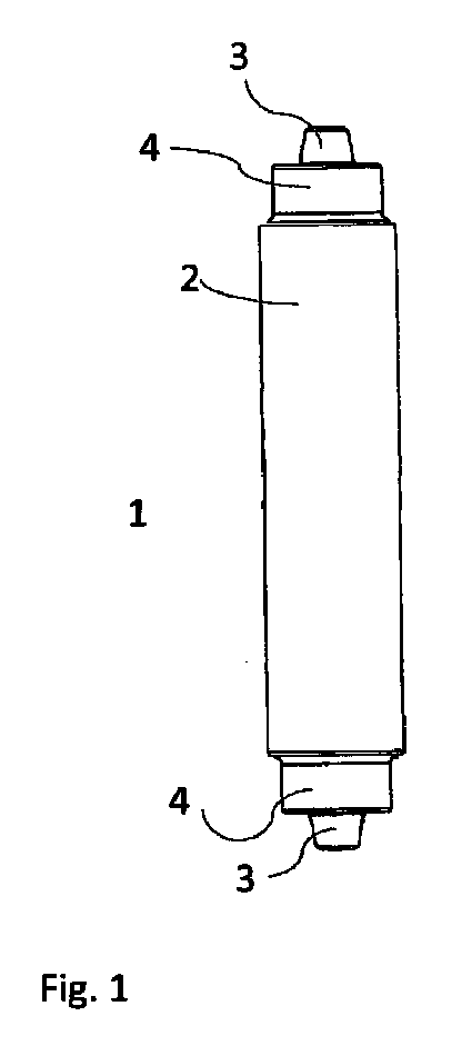
図1は、本発明の実施形態による摩擦撹拌接合工具1を示す。工具1は本体2を含み、工具の各端部に段部4及びプローブ3が存在する。摩擦撹拌接合工具1は超硬合金から作られ、工具1は完全に被覆される。すなわち工具1すなわち本体2の全外面、段部4、及びプローブ3は、表面コーティングをコーティングされる。
FIG. 1 shows a friction
摩擦撹拌接合工具1上では、2個のプローブ3が、摩擦撹拌接合工程において第1のプローブが活動状態であるとき、第2のプローブが非活動状態であるように互いに反対側に配置される。摩擦撹拌接合工程の間、溶接される2枚の板の間にプローブ3の一方が位置し、その段部4が継目の真上に位置する。摩擦撹拌接合工程の間、活動状態なのは、一度に一方のプローブ3のみである。もう一方のプローブ3は、例えば第1のプローブが摩滅した場合に使用することができる。
On the friction
下記の実施例は本発明を例示することを目的とする。 The following examples are intended to illustrate the present invention.
実施例1:耐化学性試験
試料A、B、C、及びDを、試料を低炭素鋼中に部分的に投ずる鋳造試験においてそれらの耐化学性に関して評価した。
Example 1: Chemical resistance test Samples A, B, C, and D were evaluated for their chemical resistance in a casting test in which the samples were partially cast into low carbon steel.
試料A、B、C、及びDはそれぞれ、5μmの粒子サイズ(Jeffriesの測面法、ASTM E112に従って測定される)を有するWCを90wt%、Coを4.7wt%、Niを4.3wt%、Crを1wt%含む超硬合金から作られる。試料A、B、及びCは、鋳造試験に先立ってCVDコーティングされた。試料Aは、TiNの厚さ3.3μmの中間コーティング及び外側のAl2O3の厚さ10μmの表面コーティングをコーティングされ、試料Bは、TiCNの厚さ4μmの表面コーティングをコーティングされ、また試料Cは、TiNの厚さ4μmの表面コーティングを有した。コーティングした試料A、B、C、及び非コーティング試料Dを低炭素鋼中に投じた。 Samples A, B, C, and D were 90 wt% WC, 4.7 wt% Co, and 4.3 wt% Ni, respectively, having a particle size of 5 μm (measured in accordance with Jeffries's surface measurement method, ASTM E112). , Made of cemented carbide containing 1 wt% Cr. Samples A, B, and C were CVD coated prior to casting testing. Sample A is coated with a TiN 3.3 μm thick intermediate coating and an outer Al 2 O 3 10 μm thick surface coating, Sample B is coated with a 4 μm thick TiCN surface coating, C had a 4 μm thick surface coating of TiN. Coated samples A, B, C and uncoated sample D were cast into low carbon steel.
この鋼の融点は1565℃である。各試料を溶融した鋼中に部分的に10分間浸漬した後、その鋼を空気中で室温まで自己冷却させた。この鋳造試験の後、部分的に投じられた各試料に関して貫通切込みが行われ、それら貫通切込み部を走査電子顕微鏡(SEM)で調べた。試料B、C、及びDはこの鋳造試験で溶解したが、試料A1は溶解の徴候を示さず、したがって良好な耐化学性を示した。これら結果の概要を表1に示す。 The melting point of this steel is 1565 ° C. After each sample was partially immersed in the molten steel for 10 minutes, the steel was allowed to self-cool to room temperature in air. After this casting test, through-cuts were made on the partially cast samples, and the through-cuts were examined with a scanning electron microscope (SEM). Samples B, C, and D were dissolved in this casting test, but sample A1 showed no signs of dissolution and therefore good chemical resistance. A summary of these results is shown in Table 1.
実施例2:酸化試験
試料E、F、及びGを調製し、それらの耐酸化性に関して試料を炉中で空気中で熱処理する酸化試験で評価した。
Example 2: Oxidation test Samples E, F, and G were prepared and evaluated for their oxidation resistance in an oxidation test in which the samples were heat treated in air in a furnace.
各試料E、F、及びGは、5μmの粒子サイズ(Jeffriesの測面法、ASTM E112に従って測定される)を有するWCを90wt%、Coを4.7wt%、Niを4.3wt%、Crを1wt%含む超硬合金から作られる。試料E、F、及びGは、酸化試験に先立ってCVDコーティングされた。試料Eは、TiNの厚さ2μmの中間コーティング及び外側のAl2O3の厚さ6μmの表面コーティングをコーティングされ、試料Fは、TiAlNの厚さ4μmの表面コーティングをコーティングされ、また試料Gは、TiNの厚さ4μmの表面コーティングを有した。コーティングした試料E、F、及びGを酸化試験において試験した。 Each sample E, F, and G is 90 wt% WC, 4.7 wt% Co, 4.3 wt% Ni, Cr having a particle size of 5 μm (measured in accordance with Jeffries's surface measurement method, ASTM E112), Cr Made of a cemented carbide containing 1 wt%. Samples E, F, and G were CVD coated prior to oxidation testing. Sample E is coated with a 2 μm thick TiN intermediate coating and a 6 μm thick surface coating of outer Al 2 O 3 , Sample F is coated with a 4 μm thick TiAlN surface coating, and Sample G is And a 4 μm thick surface coating of TiN. Coated samples E, F, and G were tested in an oxidation test.
酸化試験は、上記試料を950℃の炉中で空気中で12時間処理することを含む。試料を空気中で室温まで冷却させ、それらの試験後の外観に基づいて評価した。試料が酸化の徴候を示さなかった場合、その耐酸化性は良好とみなした。試料が酸化されるか、表面に亀裂がはいるか、又は試料全体の至るところに亀裂がはいる場合、その耐酸化性は劣っているとみなした。 The oxidation test involves treating the sample in air at 950 ° C. for 12 hours. Samples were allowed to cool to room temperature in air and evaluated based on their post-test appearance. If the sample showed no signs of oxidation, its oxidation resistance was considered good. If the sample was oxidized, cracked on the surface, or cracked throughout the sample, the oxidation resistance was considered poor.
結果が表2にまとめられる。 The results are summarized in Table 2.
実施例3:摩擦撹拌接合試験
摩擦撹拌接合試験を3種類の異なるプローブ、すなわちプローブH、プローブI、及びプローブJを用いて行った。すべてのプローブは超硬合金から作られ、先細のピンを有する円柱状の段部を有し、ピンの直径は約5mm、段部の直径は16mmである。溶接試験は、Al、Cu、又は低炭素鋼(C:0.2%、Si:0.3%、P:0.04%、S:0.05%、Fe:残分、硬さ30HRCを有する)の厚さ4mmの2枚の板間の接合部で行った。試験は、溶接速度150mm/分、最大ダウンフォース230kN、回転速度300rpm、及び傾斜角1.5oで行った。
Example 3: Friction stir welding test A friction stir welding test was performed using three different probes: probe H, probe I, and probe J. All probes are made of cemented carbide and have a cylindrical step with a tapered pin, the pin diameter is about 5 mm and the step diameter is 16 mm. Welding test was performed using Al, Cu, or low carbon steel (C: 0.2%, Si: 0.3%, P: 0.04%, S: 0.05%, Fe: remainder, hardness 30HRC. A) at a junction between two 4 mm thick plates. The test was performed at a welding speed of 150 mm / min, a maximum downforce of 230 kN, a rotational speed of 300 rpm, and an inclination angle of 1.5 ° .
プローブHはコーティングされず、いわゆるグレードC10Cの超硬合金から作られる。グレードC10Cは、Coを4.7wt%、Niを4.3wt%、Crを1wt%、WCを90wt%含む超硬合金であり、平均WC粒子サイズは5μmである。プローブHを、Al、Cu、及び低炭素鋼(上記で示した組成を有する)における摩擦撹拌接合で試験した。プローブHの摩擦撹拌接合試験は12mについて実行された。Al及びCuでのそれぞれ摩擦撹拌接合試験の結果は、試験の完了した後にプローブが損傷を示さなかったというものであった。上記低炭素鋼での摩擦撹拌接合試験の結果は、試験の完了した後にプローブの先端部分がなくなっていたというものであった。 The probe H is not coated and is made of a so-called grade C10C cemented carbide. Grade C10C is a cemented carbide containing 4.7 wt% Co, 4.3 wt% Ni, 1 wt% Cr, and 90 wt% WC, and the average WC particle size is 5 μm. Probe H was tested in friction stir welding in Al, Cu, and low carbon steel (having the composition shown above). The friction stir welding test of probe H was performed for 12 m. The result of each friction stir welding test with Al and Cu was that the probe showed no damage after the test was completed. The result of the friction stir welding test on the low carbon steel was that the probe tip was missing after the test was completed.
プローブIはコーティングされず、いわゆるグレードS6の超硬合金から作られる。グレードS6は、(Ta,Nb,Ti)Cを12wt%、Coを11wt%、WCを77wt%含む超硬合金であり、平均WC粒子サイズは2μmである。プローブIを、Al、Cu、及び低炭素鋼(上記で示した組成を有する)における摩擦撹拌接合で試験した。プローブIの摩擦撹拌接合試験は4mについて実行された。上記低炭素鋼での摩擦撹拌接合試験の結果は、試験の後にプローブの先端部分がなくなっており、また工具中に亀裂が観察されたというものであった。 Probe I is not coated and is made of a so-called grade S6 cemented carbide. Grade S6 is a cemented carbide containing 12 wt% of (Ta, Nb, Ti) C, 11 wt% of Co, and 77 wt% of WC, and the average WC particle size is 2 μm. Probe I was tested in friction stir welding in Al, Cu, and low carbon steel (having the composition shown above). The probe I friction stir welding test was performed for 4 m. The result of the friction stir welding test with the low carbon steel was that the tip of the probe disappeared after the test, and cracks were observed in the tool.
プローブJは、いわゆるグレードC10Cの超硬合金から作られ、TiNの中間コーティング及びAl2O3の外側コーティングを含む表面コーティングで完全にコーティングされる。TiNコーティングは厚さ0.3μmであり、Al2O3コーティングは厚さ15μmである。グレードC10Cは、Coを4.7wt%、Niを4.3wt%、Crを1wt%、WCを90wt%含む超硬合金であり、平均WC粒子サイズは5μmである。プローブJを、低炭素鋼(上記で示した組成を有する)において摩擦撹拌接合で試験した。プローブJの摩擦撹拌接合試験は40mについて実行された。上記低炭素鋼での摩擦撹拌接合試験結果は、工具がコーティングの損傷を示さず、また亀裂を観察することができなかったというものであった。 Probe J is made from a so-called grade C10C cemented carbide and is completely coated with a surface coating including an intermediate coating of TiN and an outer coating of Al 2 O 3 . The TiN coating is 0.3 μm thick and the Al 2 O 3 coating is 15 μm thick. Grade C10C is a cemented carbide containing 4.7 wt% Co, 4.3 wt% Ni, 1 wt% Cr, and 90 wt% WC, and the average WC particle size is 5 μm. Probe J was tested in friction stir welding on low carbon steel (having the composition shown above). The friction stir welding test of probe J was performed for 40 m. The result of the friction stir welding test with the low carbon steel was that the tool showed no coating damage and no cracks could be observed.
摩擦撹拌接合試験の結果を表3にまとめた。それは、いわゆるグレードC10Cの超硬合金から作られ、Al2O3の外層をコーティングされたプローブJの成績が良いことを示している。これは、プローブJが、鋼での摩擦撹拌接合試験の間、十分に高い耐酸化性、高い耐化学性、高強度、及び高温硬さを有することを意味する。試験の後のプローブに亀裂がないことはまた、熱機械疲労に対する高い抵抗性を示している。 The results of the friction stir welding test are summarized in Table 3. It shows that a probe J made of a so-called grade C10C cemented carbide and coated with an outer layer of Al 2 O 3 performs well. This means that probe J has sufficiently high oxidation resistance, high chemical resistance, high strength, and high temperature hardness during the friction stir welding test on steel. The absence of cracks in the probe after the test also indicates a high resistance to thermomechanical fatigue.
本発明の好ましい実施形態に関して記述したが、別添の特許請求の範囲で述べる本発明の範囲から逸脱することなしに様々な変更及び/又は修正を行うことができることは通常の当業熟練者には容易に明らかなはずである。全般的には本発明は別添の特許請求の範囲によってのみ限定されるものである。 Although described with respect to the preferred embodiment of the present invention, it will be understood by those of ordinary skill in the art that various changes and / or modifications can be made without departing from the scope of the invention as set forth in the appended claims. Should be readily apparent. In general, the present invention is limited only by the accompanying claims.
Claims (12)
Applications Claiming Priority (3)
| Application Number | Priority Date | Filing Date | Title |
|---|---|---|---|
| EP11188809.5 | 2011-11-11 | ||
| EP11188809.5A EP2591874B1 (en) | 2011-11-11 | 2011-11-11 | Friction stir welding tool made of cemented tungsten carbid with Nickel and with a Al2O3 surface coating |
| PCT/EP2012/004661 WO2013068122A1 (en) | 2011-11-11 | 2012-11-09 | Friction stir welding tool made of cemented tungsten carbid with nickel and with a al203 surface coating |
Publications (2)
| Publication Number | Publication Date |
|---|---|
| JP2015502257A JP2015502257A (en) | 2015-01-22 |
| JP6139545B2 true JP6139545B2 (en) | 2017-05-31 |
Family
ID=47358075
Family Applications (1)
| Application Number | Title | Priority Date | Filing Date |
|---|---|---|---|
| JP2014540355A Expired - Fee Related JP6139545B2 (en) | 2011-11-11 | 2012-11-09 | Friction stir welding tool made of carbide tungsten carbide containing nickel and having an AL203 surface coating |
Country Status (11)
| Country | Link |
|---|---|
| US (1) | US9656345B2 (en) |
| EP (2) | EP2591874B1 (en) |
| JP (1) | JP6139545B2 (en) |
| KR (1) | KR101963472B1 (en) |
| CN (1) | CN103930234B (en) |
| BR (1) | BR112014011207B1 (en) |
| CA (1) | CA2853870C (en) |
| DK (2) | DK2591874T3 (en) |
| ES (2) | ES2675907T3 (en) |
| MX (1) | MX356920B (en) |
| WO (1) | WO2013068122A1 (en) |
Families Citing this family (9)
| Publication number | Priority date | Publication date | Assignee | Title |
|---|---|---|---|---|
| JP2012130948A (en) * | 2010-12-22 | 2012-07-12 | Sumitomo Electric Ind Ltd | Rotating tool |
| JP2012130947A (en) * | 2010-12-22 | 2012-07-12 | Sumitomo Electric Ind Ltd | Rotation tool |
| JPWO2012086489A1 (en) * | 2010-12-22 | 2014-05-22 | 住友電気工業株式会社 | Rotation tool |
| USD762253S1 (en) * | 2011-07-29 | 2016-07-26 | Japan Transport Engineering Company | Friction stir welding tool |
| AT517894B1 (en) * | 2015-10-30 | 2018-06-15 | Univ Wien Tech | friction stir welding |
| CN105436697A (en) * | 2015-12-02 | 2016-03-30 | 浙江理工大学 | Efficient heat-insulation friction stir welding head and method |
| RU184619U1 (en) * | 2018-07-06 | 2018-11-01 | Федеральное государственное автономное образовательное учреждение высшего образования "Белгородский государственный национальный исследовательский университет" (НИУ "БелГУ") | Tungsten carbide welding tool |
| CN109822208B (en) * | 2019-03-20 | 2021-03-09 | 北京赛福斯特技术有限公司 | Double-head double-side high-efficiency friction stir welding equipment and welding method thereof |
| EP4321289A4 (en) * | 2021-04-08 | 2025-04-02 | Ntk Cutting Tools Co., Ltd. | FRICTION STIR WELDING TOOL AND FRICTION STIR WELDING METHOD |
Family Cites Families (21)
| Publication number | Priority date | Publication date | Assignee | Title |
|---|---|---|---|---|
| JPS61110771A (en) * | 1984-11-06 | 1986-05-29 | Hitachi Metals Ltd | Surface covered sintered hard alloy |
| JPH06170611A (en) * | 1986-01-27 | 1994-06-21 | Mitsubishi Materials Corp | Surface coating tungsten carbide base cemented carbide cutting tool |
| JPH06262407A (en) * | 1993-03-16 | 1994-09-20 | Mitsubishi Materials Corp | Surface-coated tungsten carbide based cemented carbide cutting tool with excellent fracture resistance |
| SE502223C2 (en) * | 1994-01-14 | 1995-09-18 | Sandvik Ab | Methods and articles when coating a cutting tool with an alumina layer |
| JP3127708B2 (en) * | 1994-03-11 | 2001-01-29 | 住友電気工業株式会社 | Coated cemented carbide for cutting tools |
| US6022175A (en) * | 1997-08-27 | 2000-02-08 | Kennametal Inc. | Elongate rotary tool comprising a cermet having a Co-Ni-Fe binder |
| US6911063B2 (en) * | 2003-01-13 | 2005-06-28 | Genius Metal, Inc. | Compositions and fabrication methods for hardmetals |
| US7273665B2 (en) * | 2003-12-22 | 2007-09-25 | Mitsubishi Materials Corporation | Surface-coated cermet cutting tool with hard coating layer having excellent chipping resistance |
| US7198189B2 (en) * | 2004-09-28 | 2007-04-03 | Alcoa Inc. | Multi-shouldered fixed bobbin tools for simultaneous friction stir welding of multiple parallel walls between parts |
| SE528673C2 (en) * | 2005-01-03 | 2007-01-16 | Sandvik Intellectual Property | Coated cemented carbide inserts for dry milling in high-alloy gray cast iron and method and use |
| US7357292B2 (en) * | 2005-02-01 | 2008-04-15 | Battelle Energy Alliance, Llc | Friction stir welding tool |
| SE529015C2 (en) * | 2005-09-09 | 2007-04-10 | Sandvik Intellectual Property | PVD coated cutting tool inserts made of cemented carbide |
| JP2007268605A (en) * | 2006-03-31 | 2007-10-18 | Kawasaki Heavy Ind Ltd | Friction stir welding equipment |
| JP4869817B2 (en) * | 2006-07-28 | 2012-02-08 | 川崎重工業株式会社 | Friction stir welding equipment |
| AT506133B1 (en) * | 2007-11-16 | 2009-11-15 | Boehlerit Gmbh & Co Kg | friction stir welding tool |
| JP5326096B2 (en) * | 2008-03-12 | 2013-10-30 | アイセル株式会社 | Friction stir processing tool |
| JP5441028B2 (en) * | 2009-04-30 | 2014-03-12 | 国立大学法人大阪大学 | Rotation tool |
| KR101344170B1 (en) * | 2009-12-17 | 2013-12-20 | 스미토모덴키고교가부시키가이샤 | Cloth turning tool |
| EP2439300A1 (en) * | 2010-10-08 | 2012-04-11 | Sandvik Intellectual Property AB | Cemented carbide |
| JP2012130947A (en) * | 2010-12-22 | 2012-07-12 | Sumitomo Electric Ind Ltd | Rotation tool |
| JP2012130948A (en) * | 2010-12-22 | 2012-07-12 | Sumitomo Electric Ind Ltd | Rotating tool |
-
2011
- 2011-11-11 ES ES11188809.5T patent/ES2675907T3/en active Active
- 2011-11-11 DK DK11188809.5T patent/DK2591874T3/en active
- 2011-11-11 EP EP11188809.5A patent/EP2591874B1/en not_active Not-in-force
-
2012
- 2012-11-09 DK DK12801448.7T patent/DK2776204T3/en active
- 2012-11-09 ES ES12801448T patent/ES2737676T3/en active Active
- 2012-11-09 KR KR1020147014351A patent/KR101963472B1/en active Active
- 2012-11-09 MX MX2014005506A patent/MX356920B/en active IP Right Grant
- 2012-11-09 CN CN201280055350.7A patent/CN103930234B/en not_active Expired - Fee Related
- 2012-11-09 CA CA2853870A patent/CA2853870C/en not_active Expired - Fee Related
- 2012-11-09 EP EP12801448.7A patent/EP2776204B1/en not_active Not-in-force
- 2012-11-09 BR BR112014011207-0A patent/BR112014011207B1/en not_active IP Right Cessation
- 2012-11-09 US US14/357,257 patent/US9656345B2/en active Active
- 2012-11-09 JP JP2014540355A patent/JP6139545B2/en not_active Expired - Fee Related
- 2012-11-09 WO PCT/EP2012/004661 patent/WO2013068122A1/en not_active Ceased
Also Published As
| Publication number | Publication date |
|---|---|
| MX356920B (en) | 2018-06-20 |
| EP2776204B1 (en) | 2019-05-08 |
| US20140312099A1 (en) | 2014-10-23 |
| EP2591874A1 (en) | 2013-05-15 |
| MX2014005506A (en) | 2014-06-05 |
| CA2853870A1 (en) | 2013-05-16 |
| DK2591874T3 (en) | 2018-07-23 |
| BR112014011207B1 (en) | 2019-09-24 |
| ES2675907T3 (en) | 2018-07-13 |
| EP2776204A1 (en) | 2014-09-17 |
| JP2015502257A (en) | 2015-01-22 |
| CN103930234B (en) | 2017-05-10 |
| CN103930234A (en) | 2014-07-16 |
| BR112014011207A2 (en) | 2017-05-09 |
| WO2013068122A1 (en) | 2013-05-16 |
| ES2737676T3 (en) | 2020-01-15 |
| CA2853870C (en) | 2020-03-24 |
| US9656345B2 (en) | 2017-05-23 |
| KR101963472B1 (en) | 2019-03-28 |
| KR20140098758A (en) | 2014-08-08 |
| EP2591874B1 (en) | 2018-05-16 |
| DK2776204T3 (en) | 2019-07-15 |
Similar Documents
| Publication | Publication Date | Title |
|---|---|---|
| JP6139545B2 (en) | Friction stir welding tool made of carbide tungsten carbide containing nickel and having an AL203 surface coating | |
| TWI470088B (en) | Hard alloy and cutting tools using it | |
| CN102958639B (en) | rotary tool | |
| WO2011053928A1 (en) | Glass forming hardbanding material | |
| JP4517008B1 (en) | High temperature material conveying member | |
| WO2012086488A1 (en) | Rotating tool | |
| WO2012086490A1 (en) | Rotary tool | |
| WO2012086489A1 (en) | Rotating tool | |
| TWI302949B (en) | ||
| JP2012139694A (en) | Coated rotating tool | |
| JP4412563B2 (en) | High temperature material conveying member | |
| JP2019183201A (en) | Sintered body and rotation tool | |
| JP5708105B2 (en) | Rotation tool | |
| JP6036795B2 (en) | Rotation tool | |
| JP6578532B2 (en) | Heat-resistant alloy tool having a coating layer and processing apparatus | |
| JP2015107525A (en) | Rotary tool | |
| JP6039004B2 (en) | Rotation tool | |
| Lisiecka et al. | Atmospheric Plasma Spraying (APS) and Alloying as Methods to Modify Properties of the SSS Surface Layers | |
| Yao et al. | A Hybrid Thermal Spray and Sinter Fusion Process to Apply Wear and Corrosion Resistant Coatings | |
| JP2012166219A (en) | Rotary tool | |
| Chen et al. | Wear resistance of SK3 carbon tool steel coated a thin layer of cobalt base alloy and poly crystalline diamond by laser brazing |
Legal Events
| Date | Code | Title | Description |
|---|---|---|---|
| A621 | Written request for application examination |
Free format text: JAPANESE INTERMEDIATE CODE: A621 Effective date: 20150909 |
|
| RD02 | Notification of acceptance of power of attorney |
Free format text: JAPANESE INTERMEDIATE CODE: A7422 Effective date: 20160606 |
|
| A131 | Notification of reasons for refusal |
Free format text: JAPANESE INTERMEDIATE CODE: A131 Effective date: 20160719 |
|
| A977 | Report on retrieval |
Free format text: JAPANESE INTERMEDIATE CODE: A971007 Effective date: 20160720 |
|
| A02 | Decision of refusal |
Free format text: JAPANESE INTERMEDIATE CODE: A02 Effective date: 20161011 |
|
| A521 | Request for written amendment filed |
Free format text: JAPANESE INTERMEDIATE CODE: A523 Effective date: 20170209 |
|
| A911 | Transfer to examiner for re-examination before appeal (zenchi) |
Free format text: JAPANESE INTERMEDIATE CODE: A911 Effective date: 20170224 |
|
| TRDD | Decision of grant or rejection written | ||
| A01 | Written decision to grant a patent or to grant a registration (utility model) |
Free format text: JAPANESE INTERMEDIATE CODE: A01 Effective date: 20170411 |
|
| A61 | First payment of annual fees (during grant procedure) |
Free format text: JAPANESE INTERMEDIATE CODE: A61 Effective date: 20170427 |
|
| R150 | Certificate of patent or registration of utility model |
Ref document number: 6139545 Country of ref document: JP Free format text: JAPANESE INTERMEDIATE CODE: R150 |
|
| S111 | Request for change of ownership or part of ownership |
Free format text: JAPANESE INTERMEDIATE CODE: R313113 |
|
| R350 | Written notification of registration of transfer |
Free format text: JAPANESE INTERMEDIATE CODE: R350 |
|
| S533 | Written request for registration of change of name |
Free format text: JAPANESE INTERMEDIATE CODE: R313533 |
|
| R350 | Written notification of registration of transfer |
Free format text: JAPANESE INTERMEDIATE CODE: R350 |
|
| R250 | Receipt of annual fees |
Free format text: JAPANESE INTERMEDIATE CODE: R250 |
|
| LAPS | Cancellation because of no payment of annual fees |