JP6139537B2 - Vacuum cleaner - Google Patents
Vacuum cleaner Download PDFInfo
- Publication number
- JP6139537B2 JP6139537B2 JP2014535111A JP2014535111A JP6139537B2 JP 6139537 B2 JP6139537 B2 JP 6139537B2 JP 2014535111 A JP2014535111 A JP 2014535111A JP 2014535111 A JP2014535111 A JP 2014535111A JP 6139537 B2 JP6139537 B2 JP 6139537B2
- Authority
- JP
- Japan
- Prior art keywords
- vanes
- vacuum cleaner
- diffuser
- pair
- air flow
- Prior art date
- Legal status (The legal status is an assumption and is not a legal conclusion. Google has not performed a legal analysis and makes no representation as to the accuracy of the status listed.)
- Expired - Fee Related
Links
Images


Classifications
-
- A—HUMAN NECESSITIES
- A47—FURNITURE; DOMESTIC ARTICLES OR APPLIANCES; COFFEE MILLS; SPICE MILLS; SUCTION CLEANERS IN GENERAL
- A47L—DOMESTIC WASHING OR CLEANING; SUCTION CLEANERS IN GENERAL
- A47L11/00—Machines for cleaning floors, carpets, furniture, walls, or wall coverings
- A47L11/40—Parts or details of machines not provided for in groups A47L11/02 - A47L11/38, or not restricted to one of these groups, e.g. handles, arrangements of switches, skirts, buffers, levers
- A47L11/4097—Means for exhaust-air diffusion; Exhaust-air treatment, e.g. air purification; Means for sound or vibration damping
-
- A—HUMAN NECESSITIES
- A47—FURNITURE; DOMESTIC ARTICLES OR APPLIANCES; COFFEE MILLS; SPICE MILLS; SUCTION CLEANERS IN GENERAL
- A47L—DOMESTIC WASHING OR CLEANING; SUCTION CLEANERS IN GENERAL
- A47L5/00—Structural features of suction cleaners
- A47L5/12—Structural features of suction cleaners with power-driven air-pumps or air-compressors, e.g. driven by motor vehicle engine vacuum
- A47L5/22—Structural features of suction cleaners with power-driven air-pumps or air-compressors, e.g. driven by motor vehicle engine vacuum with rotary fans
-
- F—MECHANICAL ENGINEERING; LIGHTING; HEATING; WEAPONS; BLASTING
- F04—POSITIVE - DISPLACEMENT MACHINES FOR LIQUIDS; PUMPS FOR LIQUIDS OR ELASTIC FLUIDS
- F04D—NON-POSITIVE-DISPLACEMENT PUMPS
- F04D29/00—Details, component parts, or accessories
- F04D29/40—Casings; Connections of working fluid
- F04D29/42—Casings; Connections of working fluid for radial or helico-centrifugal pumps
- F04D29/4206—Casings; Connections of working fluid for radial or helico-centrifugal pumps especially adapted for elastic fluid pumps
- F04D29/4226—Fan casings
- F04D29/4253—Fan casings with axial entry and discharge
-
- F—MECHANICAL ENGINEERING; LIGHTING; HEATING; WEAPONS; BLASTING
- F04—POSITIVE - DISPLACEMENT MACHINES FOR LIQUIDS; PUMPS FOR LIQUIDS OR ELASTIC FLUIDS
- F04D—NON-POSITIVE-DISPLACEMENT PUMPS
- F04D29/00—Details, component parts, or accessories
- F04D29/40—Casings; Connections of working fluid
- F04D29/42—Casings; Connections of working fluid for radial or helico-centrifugal pumps
- F04D29/44—Fluid-guiding means, e.g. diffusers
- F04D29/441—Fluid-guiding means, e.g. diffusers especially adapted for elastic fluid pumps
- F04D29/444—Bladed diffusers
Landscapes
- Engineering & Computer Science (AREA)
- Mechanical Engineering (AREA)
- General Engineering & Computer Science (AREA)
- Structures Of Non-Positive Displacement Pumps (AREA)
- Electric Suction Cleaners (AREA)
Description
本発明は掃除機に関し、特にアキシャルディフューザ(axial diffuser)を含む掃除機に関する。 The present invention relates to a vacuum cleaner, and more particularly, to a vacuum cleaner including an axial diffuser.
電動送風機の効率は、掃除機の損失を最小化する上で重要な要素である。送風機システムのうち、現在のシステムで不必要な損失が見られる部分は、空気案内システムの中にある。通常、ディフューザが存在するのは、羽根車から吹き出された空気を制御された方法で減速させ、そのようにして羽根車により発生する動圧を静圧に変換するためである。掃除機の中のディフューザは、軸方向または径方向のいずれかで配置される。ディフューザの構成は、それが掃除機の効率に影響を与えるため、非常に重要である。高効率のディフューザにより、移動される空気の体積を増大でき、または同じ体積の空気を移動させるのに必要な電力が少なくてすむ。したがって、より効率の高いディフューザが求められるのは明らかである。 The efficiency of the electric blower is an important factor in minimizing the loss of the vacuum cleaner. The portion of the blower system where unnecessary losses are seen in the current system is in the air guidance system. The diffuser is usually present in order to decelerate the air blown from the impeller in a controlled manner and thus convert the dynamic pressure generated by the impeller into a static pressure. The diffuser in the vacuum cleaner is arranged either axially or radially. The configuration of the diffuser is very important because it affects the efficiency of the vacuum cleaner. A highly efficient diffuser can increase the volume of air being moved or require less power to move the same volume of air. Therefore, it is clear that a more efficient diffuser is required.
特許文献1において、径方向に配置されたディフューザを備える掃除機が提供されている。既知の構成では、ディフューザ内のベーン(vanes)の入口角度を変えることにより、リターンガイドベーンの角度を変化させることと組み合わせたときに、効率が向上する。ディフューザを径方向に配置すると、掃除機の直径が大きくなり、したがって、よりコンパクトな設計が望まれる場合にはディフューザを軸方向に配置することが好ましい。たとえば、大きさが重要な要素となるハンドヘルド型掃除機においては、アキシャルディフューザにより、径方向に配置されたディフューザより小さい外径の設計が可能になる。
In
特許文献2は、電気モータに直接接続された斜流羽根車(mixed flow impeller)と、羽根車の下流側に配置されたアキシャルディフューザと、を備える掃除機を開示している。
ディフューザの一般的な課題は、損失を極小化するために空気をできるだけスムーズに減速させるべきである、という点である。ディフューザの空気流路の流路面積を少しずつ増大させることによって、スムーズな減速が達成される。これは、空気流路が比較的長ければ容易に達成される。長い流路のディフューザを製作する際の問題は、生産工具が結局、非常に複雑となることである。たとえば、射出成形によってディフューザを製造する場合、空気をスムーズに減速させるのに十分な長さの空気流路を有するディフューザを製造するには、射出成形用の工具を極めて複雑にする必要がある。長い流路と断面積が増大するような流路から生じる他の問題は境界層の剥離であり、すなわち、空気流が流れる流路表面から空気流が剥離し、その結果、流れの抵抗が大きくなって損失が増大する。比較的長いベーンを有する1列のディフューザを備える構成では、境界層が減速して停止し、剥離が生じるリスクがある。 The general challenge of diffusers is that the air should be decelerated as smoothly as possible to minimize losses. Smooth deceleration is achieved by gradually increasing the flow area of the air flow path of the diffuser. This is easily achieved if the air flow path is relatively long. The problem with making long channel diffusers is that the production tools are ultimately very complex. For example, when manufacturing a diffuser by injection molding, it is necessary to make an injection molding tool extremely complicated in order to manufacture a diffuser having an air flow path long enough to smoothly decelerate air. Another problem that arises from long channels and channels that increase cross-sectional area is the separation of the boundary layer, i.e., the air flow separates from the surface of the channel through which the air flow flows, resulting in high flow resistance. As a result, the loss increases. In a configuration with a single row of diffusers with relatively long vanes, the boundary layer slows down and stops and there is a risk of delamination.
さらに、一般に利用可能なエネルギーがコストおよび/または空間面のいずれかの制約によって限定されるバッテリ式掃除機には、できるだけ損失の小さい、コンパクトで効率的な電動送風機が必要となる。したがって、コンパクトな設計および損失の少ない効率的な送風機システムの両方を提供する改良された掃除機に対するニーズがある。 In addition, battery-powered vacuum cleaners where the available energy is generally limited by either cost and / or space constraints require a compact and efficient electric blower with as little loss as possible. Thus, there is a need for an improved vacuum cleaner that provides both a compact design and a low loss and efficient blower system.
本発明の目的は、上記の問題の少なくともいくつかを解決する改良された掃除機を提供することである。 It is an object of the present invention to provide an improved vacuum cleaner that solves at least some of the above problems.
本発明の第一の態様によれば、この目的は、共通軸上に配置された電動機と、羽根車と、アキシャルディフューザと、を含む掃除機によって達成される。羽根車は電動機に接続され、共通軸上で回転して径方向の空気流を起こすように配置される。径方向の空気流は軸方向の空気流へと転向される。ディフューザ通路は、内周壁と外周壁の間に配置される。これらの壁は、共通軸の周囲に同軸的に配置される。各ディフューザ通路は、壁間で円周方向に、内周壁と外周壁の間において共通軸に対して実質的に平行に走る軸方向へと延びるベーンによって区切られる。ベーンは少なくとも2列に配置され、これらは共通軸に対して実質的に平行に走る軸方向へと連続的に配される。 According to a first aspect of the invention, this object is achieved by a vacuum cleaner comprising an electric motor arranged on a common shaft, an impeller and an axial diffuser. The impeller is connected to an electric motor and is arranged to rotate on a common shaft and generate a radial air flow. The radial air flow is diverted to an axial air flow. The diffuser passage is disposed between the inner peripheral wall and the outer peripheral wall. These walls are arranged coaxially around a common axis. Each diffuser passage is circumferentially walls, delimited by vanes extending in the axial direction running substantially parallel to the common axis between the inner peripheral wall and the outer circumferential wall. The vanes are arranged in at least two rows, which are arranged continuously in an axial direction running substantially parallel to the common axis.
ベーンは、連続する少なくとも2列に配置されるため、流路表面が中断される。同じ長さで中断のない表面と比較して、中断された流路表面の場合は空気流れが追従する距離がより長くなるが、これは列間の推移により下流の列のベーンに沿った境界層がより安定するからである。その結果、望ましくない流路表面から空気流の剥離が回避され、空気流がディフューザ通路の利用可能な断面積全体にわたって分散される。したがって、不必要な損失が避けられ、それによってディフューザ内の損失が制限される。その結果、上記の目的が達成される。連続する複数のディフューザ列を備える構成であれば剥離と損失が最小限にとなり、これは下流のベーンの表面に新たな境界層が新しく作られることによる。複数のディフューザ列により、1列の場合より高い仕事率が得られることがわかっている。 Since the vanes are arranged in at least two consecutive rows, the surface of the flow path is interrupted. Compared to an uninterrupted surface of the same length, an interrupted channel surface will have a longer distance that the air flow will follow, but this is due to the transition between the rows, which is the boundary along the downstream row of vanes. This is because the layer is more stable. As a result, undesired separation of the air flow from the surface of the flow path is avoided and the air flow is distributed throughout the available cross-sectional area of the diffuser passage. Thus, unnecessary losses are avoided, thereby limiting the losses in the diffuser. As a result, the above object is achieved. A configuration with a series of diffuser rows minimizes delamination and loss due to the creation of a new boundary layer on the downstream vane surface. It has been found that a plurality of diffuser rows can provide a higher power than a single row.
実施形態において、ベーンは3つ以上の連続する列として配置される。さらに多くの列を使用することによって、上述のような流路表面の中断の効果が一層高まる。さらに、複数の列により、ディフューザ通路の断面積がスムーズに増大し、その結果、空気流れはスムーズに減速する。 In an embodiment, the vanes are arranged as three or more consecutive rows. By using more rows, the effect of interrupting the flow path surface as described above is further enhanced. Further, the plurality of rows smoothly increases the cross-sectional area of the diffuser passage, and as a result, the air flow is smoothly decelerated.
実施形態において、少なくとも2つのペアのベーンが連続的に配された列として配置される。 In an embodiment, at least two pairs of vanes are arranged as a continuously arranged row.
実施形態において、第一のペアのベーンは共通軸に関して第一の角度で配置され、第二のペアのベーンは共通軸に関して第二の角度で配置される。第二の角度は第一の角度より小さい。それによって、連続する各列について、空気流の方向に向かって、1つのペアに含まれる2つのベーン間の通路の幅は増大し、ディフューザ通路の断面積が増大し、それゆえ通路を流れる空気流れの流路面積が増大する。 In an embodiment, the first pair of vanes is disposed at a first angle with respect to the common axis, and the second pair of vanes is disposed at a second angle with respect to the common axis. The second angle is smaller than the first angle. Thereby, for each successive row, in the direction of the air flow, the width of the passage between the two vanes contained in one pair increases, the cross-sectional area of the diffuser passage increases and hence the air flowing through the passage. The flow area of the flow increases.
実施形態において、第一のペアに含まれるベーンは実質的に平行に、相互から離間して配置される。 In an embodiment, the vanes included in the first pair are arranged substantially parallel and spaced from each other.
実施形態において、第二のペアのベーンは、第一のペアのベーンに対して円周方向にずらして配置される。 In the embodiment, the second pair of vanes are arranged offset in the circumferential direction with respect to the first pair of vanes.
実施形態において、ずれは距離に0.15〜0.35倍を乗じた長さである。 In the embodiment, the deviation is a length obtained by multiplying the distance by 0.15 to 0.35 times.
実施形態において、電動機はバッテリで駆動される。 In the embodiment, the electric motor is driven by a battery.
実施形態において、掃除機は直立型である。 In an embodiment, the vacuum cleaner is upright.
本発明のその他の特徴と利点は、添付の特許請求の範囲と以下の詳細な説明を読むことによって明らかとなるであろう。当業者であれば、添付の特許請求の範囲により定義される本発明の範囲から逸脱せずに、本発明の異なる特徴を組み合わせて、以下に説明されるもの以外の実施形態を創出できることに気付くであろう。 Other features and advantages of the present invention will become apparent upon reading the appended claims and the following detailed description. Those skilled in the art will recognize that different features of the present invention can be combined to create embodiments other than those described below without departing from the scope of the present invention as defined by the appended claims. Will.
本発明の各種の態様は、その具体的な特徴と利点を含め、以下の詳細な説明と添付の図面から容易に理解されるであろう。 Various aspects of the present invention, including its specific features and advantages, will be readily understood from the following detailed description and the accompanying drawings.
ここで、例示的な実施形態が示されている添付の図面を参照しながら本発明をより詳しく説明する。しかしながら、本発明は本明細書に記載されている実施形態に限定されると解釈するべきではない。例示的実施形態に関して開示されている特徴は、本発明の属する業界の当業者であれば容易にわかるように、組み合わせることもできる。図面全体にわたり、同様の参照番号は同様の要素を指す。 The present invention will now be described in more detail with reference to the accompanying drawings, in which exemplary embodiments are shown. However, this invention should not be construed as limited to the embodiments set forth herein. Features disclosed with respect to the exemplary embodiments can be combined as will be readily apparent to one of ordinary skill in the art to which this invention belongs. Like reference numerals refer to like elements throughout the drawings.
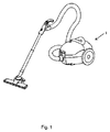
図1は、従来の掃除機を示す。掃除機1は、羽根車とディフューザを含むモータファンシステムを備える掃除機本体を含む。一般に、このような掃除機の本体は比較的大きな直径を有し、これは少なくともひとつには、ディフューザが径方向に配置され、空気の通路が羽根車の径方向に外側に配置されることによる。
FIG. 1 shows a conventional vacuum cleaner. The
図2は、本発明による掃除機1の内部を示す。掃除機1は、電動機2と、羽根車3と、アキシャルディフューザ4と、を含み、これらは共通軸5の上に配置されている。羽根車3は電動機2に接続され、共通軸5の上で回転して径方向の空気流を発生させるように配置される。アキシャルディフューザ4は、複数のディフューザ通路6を含む。径方向の空気流は軸方向の空気流に方向転換される。軸方向の空気流を達成するために、径方向の空気流は羽根車とディフューザの間にあるベーンのない空間(図示せず)の中で方向転換される。アキシャルディフューザ4は、ベーンのない空間から出る空気の実質的に周方向の速度をより軸方向へと偏向させるように配置される。ディフューザ通路6は内周壁7と外周壁8の間に配置される。壁7、8は共通軸5の周囲に同軸的に配置される。各ディフューザ通路6は、内周壁7と外周壁8の間に配置され、少なくとも部分的に共通軸5と平行な軸方向に延びるベーン9によって円周方向に区切られる。図の実施形態におけるベーン9は、連続する3列10a、10b、10cに配置されている。しかしながら、設計される具体的な掃除機によって、ベーン9が連続して配置される列の数はいくつでもよい。
FIG. 2 shows the interior of the
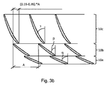
図3aと3bは、円周方向にディフューザ通路6を区切るディフューザベーン9の配置の詳細を示す。空気流の主な方向は、矢印によって示されている。図の具体的な実施形態において、ベーン9は3つの連続する列10a、10b、10cの中のペアとして配置される。1つのペアに含まれるベーン9は、相互に実質的に平行に配置される。第一のペアのベーン9a、9bは、共通軸5に関して第一の角度αで配置される。共通軸5に関して、第二のペアのベーン9c、9dは第二の角度βで配置され、第三のペアのベーン9e、9fは第三の角度γで配置される。列10a、10b、10cの各々についてベーン9の角度が小さくなり、それによって連続する列10の各々について、各ペアに含まれる2つのベーン間の通路の幅が広くなる。その結果、ディフューザ通路6の断面積および、それゆえ通路内を流れる空気流れの流路面積は空気流の方向に増大する。ベーン9の配置によって、流路面積のスムーズな増大が達成される。第一のペアに含まれる第一のベーン9a、9bは相互からの距離Aで配置され、第二のペアに含まれる第二のベーン(9c、9d)も同様である。
3a and 3b show the details of the arrangement of the diffuser vanes 9 that delimit the diffuser passage 6 in the circumferential direction. The main direction of air flow is indicated by arrows. In the particular embodiment shown, the vanes 9 are arranged as pairs in three consecutive rows 10a, 10b, 10c. The vanes 9 included in one pair are arranged substantially parallel to each other. The first pair of
またさらに、第二のペアのベーン9c、9dは、第一のペアのベーン9a、9bに関して円周方向にずらして配置される。一般に、ずれは距離Aの0.15〜0.35倍になるように選択される。当初述べた製造上の利点に加えて、このずれは、ディフューザ通路6の大部分で安定した空気の流れを保持するのに役立つ。前述のように、隣接するベーン9fの上流のベーン9dは空気流を隣接するベーン9fへと案内するほか、スロットを提供する。このスロットを通じて、隣接するディフューザ通路からの空気が隣接するベーン9fに沿って流れ、安定した境界層が生じやすくなる。
Still further, the second pair of vanes 9c, 9d are arranged to be shifted in the circumferential direction with respect to the first pair of
図4は、ハンドヘルド直立型掃除機1を示す。図からわかるように、直径が大きな設計は嵩張り、それゆえ使用者にとって使い心地が悪く、不便である。したがって、直立型の掃除機は、本発明を実施した場合に設計が改善される掃除機の、また別の例である。
FIG. 4 shows a handheld
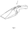
図5は、ハンドヘルド型掃除機1を示す。このタイプの掃除機は一般に、内蔵された充電式バッテリによって駆動されるか、カーバッテリ等の車両バッテリによって駆動されるように構成される。それゆえ、利用可能な電力は限定される。またさらに、使用者がその掃除機は使い勝手がよく、使いやすいと感じるように、設計をコンパクトでスリムなものとする必要がある。このような掃除機はそれゆえ、本発明を実施した場合に設計が改善される掃除機の一例である。
FIG. 5 shows the
上述の例示的実施形態は、当業者であればわかるように、組み合わせてもよい。本発明を例示的実施形態に関して説明したが、多くの異なる改変形態、改良形態などが当業者にとって明らかになるであろう。したがって、当然のことながら、前述のものは各種の例示的実施形態の説明であり、本発明は開示された具体的な実施形態に限定されず、開示された実施形態の改良形態、開示された実施形態の特徴の組み合わせ、およびその他の実施形態は、付属の特許請求項の範囲内に含められるものとする。 The exemplary embodiments described above may be combined as will be appreciated by those skilled in the art. Although the present invention has been described with reference to exemplary embodiments, many different modifications, improvements, etc. will become apparent to those skilled in the art. Thus, it should be understood that the foregoing is a description of various exemplary embodiments, and that the invention is not limited to the specific embodiments disclosed, and that modifications to the disclosed embodiments have been disclosed. Combinations of features of the embodiments, and other embodiments, are intended to be included within the scope of the appended claims.
Claims (9)
前記ディフューザ通路(6)が内周壁(7)と外周壁(8)の間に配置され、前記壁(7、8)が前記共通軸(5)の周囲に同軸的に配置され、
各ディフューザ通路(6)が、円周方向に前記壁(7、8)間で、前記内周壁(7)と前記外周壁(8)との間において少なくとも部分的に前記共通軸(5)と平行な軸方向に延びるベーン(9a〜f)によって区切られている掃除機(1)において、
前記ベーン(9)が、前記共通軸(5)に平行な前記軸方向に連続的に配置された少なくとも2つの列(10)に配置されることを特徴とする掃除機(1)。 An electric motor (2) disposed on a common shaft (5), an impeller (3), and an axial diffuser (4), the impeller (3) being connected to the electric motor (2) , Configured to generate a radial air flow by rotating on the common shaft (5), and the radial air flow into an axial air flow (6) in the diffuser passage (6) of the axial diffuser (4). It is turning in,
The diffuser passage (6) is disposed between an inner peripheral wall (7) and an outer peripheral wall (8), and the walls (7, 8) are coaxially disposed around the common shaft (5),
Each diffuser passage (6) between said walls (7,8) in the circumferential direction, at least in part on the common axis between said inner peripheral wall (7) and the outer circumferential wall (8) (5 ) In a vacuum cleaner (1) delimited by vanes (9a-f) extending in the axial direction parallel to
The vacuum cleaner (1), wherein the vanes (9) are arranged in at least two rows (10) arranged continuously in the axial direction parallel to the common axis (5).
Applications Claiming Priority (3)
| Application Number | Priority Date | Filing Date | Title |
|---|---|---|---|
| SE1100756-4 | 2011-10-13 | ||
| SE1100756 | 2011-10-13 | ||
| PCT/EP2012/070331 WO2013053920A1 (en) | 2011-10-13 | 2012-10-12 | Vacuum cleaner |
Publications (2)
| Publication Number | Publication Date |
|---|---|
| JP2014533989A JP2014533989A (en) | 2014-12-18 |
| JP6139537B2 true JP6139537B2 (en) | 2017-05-31 |
Family
ID=47018220
Family Applications (1)
| Application Number | Title | Priority Date | Filing Date |
|---|---|---|---|
| JP2014535111A Expired - Fee Related JP6139537B2 (en) | 2011-10-13 | 2012-10-12 | Vacuum cleaner |
Country Status (6)
| Country | Link |
|---|---|
| US (1) | US9456728B2 (en) |
| EP (1) | EP2765893B1 (en) |
| JP (1) | JP6139537B2 (en) |
| KR (1) | KR102017918B1 (en) |
| CN (1) | CN103889295B (en) |
| WO (1) | WO2013053920A1 (en) |
Cited By (1)
| Publication number | Priority date | Publication date | Assignee | Title |
|---|---|---|---|---|
| JP2729946B2 (en) | 1988-08-31 | 1998-03-18 | スズキ株式会社 | Transmission for vehicles |
Families Citing this family (18)
| Publication number | Priority date | Publication date | Assignee | Title |
|---|---|---|---|---|
| CN104088812B (en) * | 2013-04-01 | 2017-05-17 | 苏州三星电子有限公司 | Axial-flow fan |
| US9757000B2 (en) | 2013-12-24 | 2017-09-12 | Samsung Electronics Co., Ltd. | Cleaning device |
| KR102171271B1 (en) * | 2013-12-24 | 2020-10-28 | 삼성전자주식회사 | Cleaner |
| KR102274393B1 (en) | 2014-08-11 | 2021-07-08 | 삼성전자주식회사 | Vacuum cleaner |
| EP3015713A1 (en) * | 2014-10-30 | 2016-05-04 | Nidec Corporation | Blower apparatus |
| KR102330551B1 (en) * | 2015-03-12 | 2021-11-24 | 엘지전자 주식회사 | Vacuum suntion unit |
| JP2016223428A (en) * | 2015-05-29 | 2016-12-28 | 日本電産株式会社 | Air blower and cleaner |
| CN105626552A (en) * | 2016-02-22 | 2016-06-01 | 柴俊麟 | Spiral centrifugal fan and air treatment device |
| CN106678074A (en) * | 2017-02-22 | 2017-05-17 | 宁波高泰电器有限公司 | Fan blade and duct air feeding device applying same |
| GB2573813A (en) | 2018-05-18 | 2019-11-20 | Dyson Technology Ltd | A Compressor |
| JP7093691B2 (en) * | 2018-07-06 | 2022-06-30 | 日立グローバルライフソリューションズ株式会社 | Electric blower and vacuum cleaner equipped with it |
| JP7605580B2 (en) * | 2019-01-17 | 2024-12-24 | 日立グローバルライフソリューションズ株式会社 | Electric blower and vacuum cleaner equipped with same |
| KR20220079992A (en) | 2020-01-06 | 2022-06-14 | 광동 웰링 모터 매뉴팩처링 컴퍼니, 리미티드 | Diffusers, blowers and dust collectors |
| CN113074143B (en) * | 2020-01-06 | 2023-06-16 | 广东威灵电机制造有限公司 | Diffuser, air supply device and dust collector |
| CN113074140B (en) * | 2020-01-06 | 2022-10-18 | 广东威灵电机制造有限公司 | Diffuser, air supply device and dust collector |
| JP7514668B2 (en) * | 2020-06-29 | 2024-07-11 | 株式会社マキタ | Cleaner |
| KR20230105100A (en) * | 2022-01-03 | 2023-07-11 | 삼성전자주식회사 | Vacuum cleaner |
| GB2622028B (en) * | 2022-08-31 | 2026-02-11 | Dyson Tech Limited | Drive system for a floor cleaner |
Family Cites Families (27)
| Publication number | Priority date | Publication date | Assignee | Title |
|---|---|---|---|---|
| US2726807A (en) * | 1950-09-28 | 1955-12-13 | Finnell System Inc | Vacuum apparatus for water and dirt removal |
| US3334370A (en) | 1964-11-17 | 1967-08-08 | Gen Electric | Lightweight portable vacuum cleaner |
| NL7014555A (en) | 1970-10-03 | 1972-04-05 | ||
| GB1493844A (en) | 1974-07-16 | 1977-11-30 | Matsushita Electric Industrial Co Ltd | Electric blower assembly |
| JPS59213994A (en) * | 1983-05-19 | 1984-12-03 | Matsushita Electric Ind Co Ltd | Motor-driven blower |
| US5152661A (en) * | 1988-05-27 | 1992-10-06 | Sheets Herman E | Method and apparatus for producing fluid pressure and controlling boundary layer |
| ATE196185T1 (en) | 1992-04-14 | 2000-09-15 | Ebara Corp | PUMP HOUSING IN SHEET METAL CONSTRUCTION |
| JPH06108999A (en) | 1992-09-25 | 1994-04-19 | Hitachi Ltd | Electric blower |
| CH687637A5 (en) | 1993-11-04 | 1997-01-15 | Micronel Ag | Axialkleinventilator. |
| JP3597041B2 (en) | 1998-04-10 | 2004-12-02 | 東芝テック株式会社 | Electric blower and vacuum cleaner |
| US6055700A (en) | 1998-04-21 | 2000-05-02 | Emerson Electric Co. | Wet/dry vacuum with snap-action powerhead latch |
| US6077032A (en) | 1998-07-16 | 2000-06-20 | Felchar Manufacturing Corporation | Housing assembly for a vacuum cleaner |
| CA2281241C (en) | 1998-08-31 | 2009-05-12 | Emerson Electric Co. | Wet/dry vacuum with reduced operating noise |
| TW529406U (en) | 1999-01-29 | 2003-04-21 | Hitachi Ltd | Vacuum cleaner |
| US6264427B1 (en) | 1999-02-10 | 2001-07-24 | Shop-Vac Corporation | Vaneless impeller housing for a vacuum cleaner |
| US7025576B2 (en) | 2001-03-30 | 2006-04-11 | Chaffee Robert B | Pump with axial conduit |
| US6659737B2 (en) | 2001-02-05 | 2003-12-09 | Engineered Machined Products, Inc. | Electronic fluid pump with an encapsulated stator assembly |
| GB2377880A (en) * | 2001-07-25 | 2003-01-29 | Black & Decker Inc | Multi-operational battery powered vacuum cleaner |
| JP2006516423A (en) | 2003-01-10 | 2006-07-06 | ロイヤル アプライアンス マニュファクチュアリング カンパニー | Inhalation-type wet jet mop |
| CN1781428A (en) * | 2004-11-29 | 2006-06-07 | 乐金电子(天津)电器有限公司 | Air blower of vacuum cleaner |
| KR100721305B1 (en) | 2005-11-28 | 2007-05-28 | 삼성광주전자 주식회사 | Fan assembly for vacuum cleaner |
| US7942646B2 (en) | 2006-05-22 | 2011-05-17 | University of Central Florida Foundation, Inc | Miniature high speed compressor having embedded permanent magnet motor |
| GB0613796D0 (en) | 2006-07-12 | 2006-08-23 | Johnson Electric Sa | Blower |
| JP2009299635A (en) * | 2008-06-17 | 2009-12-24 | Hitachi Appliances Inc | Electric blower and vacuum cleaner equipped with the same |
| CN201297288Y (en) * | 2008-11-17 | 2009-08-26 | 金莱克电气股份有限公司 | Dust collector motor blower |
| EP2316322A3 (en) | 2009-11-02 | 2011-06-29 | LG Electronics Inc. | Robot cleaner |
| US20120186036A1 (en) * | 2011-01-25 | 2012-07-26 | Kegg Steven W | Diffuser for a vacuum cleaner motor-fan assembly |
-
2012
- 2012-10-12 KR KR1020147011728A patent/KR102017918B1/en active Active
- 2012-10-12 WO PCT/EP2012/070331 patent/WO2013053920A1/en not_active Ceased
- 2012-10-12 US US14/351,365 patent/US9456728B2/en active Active
- 2012-10-12 JP JP2014535111A patent/JP6139537B2/en not_active Expired - Fee Related
- 2012-10-12 CN CN201280050333.4A patent/CN103889295B/en active Active
- 2012-10-12 EP EP12772329.4A patent/EP2765893B1/en active Active
Cited By (1)
| Publication number | Priority date | Publication date | Assignee | Title |
|---|---|---|---|---|
| JP2729946B2 (en) | 1988-08-31 | 1998-03-18 | スズキ株式会社 | Transmission for vehicles |
Also Published As
| Publication number | Publication date |
|---|---|
| KR20140090172A (en) | 2014-07-16 |
| US20140230184A1 (en) | 2014-08-21 |
| CN103889295A (en) | 2014-06-25 |
| CN103889295B (en) | 2016-11-23 |
| EP2765893A1 (en) | 2014-08-20 |
| US9456728B2 (en) | 2016-10-04 |
| WO2013053920A1 (en) | 2013-04-18 |
| JP2014533989A (en) | 2014-12-18 |
| EP2765893B1 (en) | 2016-11-30 |
| KR102017918B1 (en) | 2019-09-03 |
Similar Documents
| Publication | Publication Date | Title |
|---|---|---|
| JP6139537B2 (en) | Vacuum cleaner | |
| RU2502179C2 (en) | Electric machine with double axial fan | |
| CN204551351U (en) | Hair-dryer | |
| US9217445B2 (en) | Fan | |
| US10227988B2 (en) | Blower and a blowing vacuum device | |
| US8992174B2 (en) | Fan assembly | |
| CN204715269U (en) | Hair-dryer and suction and blowing device | |
| CN104937346B (en) | Fan coil unit with cover fan | |
| JP2009537735A5 (en) | ||
| US11248615B2 (en) | Side-channel machine (compressor, vacuum pump or blower) having an extraction duct in the stripper | |
| WO2012139265A1 (en) | Centripetal pressurizing heat-generating high-temperature high-pressure ventilation compressor | |
| JP2016133105A (en) | Electric blower | |
| CN206428629U (en) | hair dryer | |
| CN104235072B (en) | Centrifugal fan and air purifier with same | |
| WO2013179256A2 (en) | Ventilation unit | |
| JP5989316B2 (en) | Electric blower and vacuum cleaner | |
| CN107401517B (en) | Air path structure of air flow device and air flow device | |
| JP2007247622A (en) | Centrifugal turbomachine | |
| CN113074127A (en) | Air supply device and dust collector | |
| CN103233900B (en) | Pipeline wheel pressurizating ventilation compressor | |
| CN215685424U (en) | A screw and equipment of blowing for equipment of blowing | |
| CN112484276B (en) | Air duct assembly and air conditioner having the same | |
| CN100353077C (en) | air outlet structure of axial flow fan | |
| CN222457820U (en) | A portable hair dryer | |
| JP7342782B2 (en) | centrifugal blower |
Legal Events
| Date | Code | Title | Description |
|---|---|---|---|
| A621 | Written request for application examination |
Free format text: JAPANESE INTERMEDIATE CODE: A621 Effective date: 20150930 |
|
| A977 | Report on retrieval |
Free format text: JAPANESE INTERMEDIATE CODE: A971007 Effective date: 20160428 |
|
| A131 | Notification of reasons for refusal |
Free format text: JAPANESE INTERMEDIATE CODE: A131 Effective date: 20160607 |
|
| A521 | Request for written amendment filed |
Free format text: JAPANESE INTERMEDIATE CODE: A523 Effective date: 20160825 |
|
| A131 | Notification of reasons for refusal |
Free format text: JAPANESE INTERMEDIATE CODE: A131 Effective date: 20170117 |
|
| A521 | Request for written amendment filed |
Free format text: JAPANESE INTERMEDIATE CODE: A523 Effective date: 20170315 |
|
| TRDD | Decision of grant or rejection written | ||
| A01 | Written decision to grant a patent or to grant a registration (utility model) |
Free format text: JAPANESE INTERMEDIATE CODE: A01 Effective date: 20170328 |
|
| A61 | First payment of annual fees (during grant procedure) |
Free format text: JAPANESE INTERMEDIATE CODE: A61 Effective date: 20170427 |
|
| R150 | Certificate of patent or registration of utility model |
Ref document number: 6139537 Country of ref document: JP Free format text: JAPANESE INTERMEDIATE CODE: R150 |
|
| R250 | Receipt of annual fees |
Free format text: JAPANESE INTERMEDIATE CODE: R250 |
|
| R250 | Receipt of annual fees |
Free format text: JAPANESE INTERMEDIATE CODE: R250 |
|
| R250 | Receipt of annual fees |
Free format text: JAPANESE INTERMEDIATE CODE: R250 |
|
| R250 | Receipt of annual fees |
Free format text: JAPANESE INTERMEDIATE CODE: R250 |
|
| R250 | Receipt of annual fees |
Free format text: JAPANESE INTERMEDIATE CODE: R250 |
|
| LAPS | Cancellation because of no payment of annual fees |