JP6139530B2 - Power generation system - Google Patents
Power generation system Download PDFInfo
- Publication number
- JP6139530B2 JP6139530B2 JP2014529272A JP2014529272A JP6139530B2 JP 6139530 B2 JP6139530 B2 JP 6139530B2 JP 2014529272 A JP2014529272 A JP 2014529272A JP 2014529272 A JP2014529272 A JP 2014529272A JP 6139530 B2 JP6139530 B2 JP 6139530B2
- Authority
- JP
- Japan
- Prior art keywords
- power
- signal
- power generation
- output
- wind
- Prior art date
- Legal status (The legal status is an assumption and is not a legal conclusion. Google has not performed a legal analysis and makes no representation as to the accuracy of the status listed.)
- Active
Links
- 238000010248 power generation Methods 0.000 title claims description 246
- 230000000694 effects Effects 0.000 claims description 48
- 239000012530 fluid Substances 0.000 claims description 38
- 230000005540 biological transmission Effects 0.000 claims description 31
- 238000006243 chemical reaction Methods 0.000 claims description 27
- 238000010438 heat treatment Methods 0.000 claims description 25
- 238000004364 calculation method Methods 0.000 claims description 23
- 238000000034 method Methods 0.000 claims description 18
- 238000012546 transfer Methods 0.000 claims description 17
- 230000008569 process Effects 0.000 claims description 16
- 230000007423 decrease Effects 0.000 claims description 12
- 239000000284 extract Substances 0.000 claims description 7
- 230000009467 reduction Effects 0.000 claims description 7
- 238000000926 separation method Methods 0.000 claims description 6
- 230000007246 mechanism Effects 0.000 claims description 4
- 238000001514 detection method Methods 0.000 claims description 3
- 230000007274 generation of a signal involved in cell-cell signaling Effects 0.000 claims description 3
- 230000001934 delay Effects 0.000 claims 1
- 230000006870 function Effects 0.000 description 60
- 238000010586 diagram Methods 0.000 description 39
- 238000000605 extraction Methods 0.000 description 8
- 238000009499 grossing Methods 0.000 description 7
- 238000012545 processing Methods 0.000 description 7
- 238000001816 cooling Methods 0.000 description 5
- 239000000498 cooling water Substances 0.000 description 4
- 238000001914 filtration Methods 0.000 description 4
- 238000013461 design Methods 0.000 description 3
- QGZKDVFQNNGYKY-UHFFFAOYSA-N Ammonia Chemical compound N QGZKDVFQNNGYKY-UHFFFAOYSA-N 0.000 description 2
- OFBQJSOFQDEBGM-UHFFFAOYSA-N Pentane Chemical compound CCCCC OFBQJSOFQDEBGM-UHFFFAOYSA-N 0.000 description 2
- 238000009835 boiling Methods 0.000 description 2
- 239000002826 coolant Substances 0.000 description 2
- 230000006641 stabilisation Effects 0.000 description 2
- 238000011105 stabilization Methods 0.000 description 2
- XLYOFNOQVPJJNP-UHFFFAOYSA-N water Substances O XLYOFNOQVPJJNP-UHFFFAOYSA-N 0.000 description 2
- 229910021529 ammonia Inorganic materials 0.000 description 1
- 238000013459 approach Methods 0.000 description 1
- 230000003750 conditioning effect Effects 0.000 description 1
- 230000003111 delayed effect Effects 0.000 description 1
- 230000006866 deterioration Effects 0.000 description 1
- 238000007599 discharging Methods 0.000 description 1
- 238000005485 electric heating Methods 0.000 description 1
- 230000005611 electricity Effects 0.000 description 1
- 238000013213 extrapolation Methods 0.000 description 1
- 239000007788 liquid Substances 0.000 description 1
- 238000012423 maintenance Methods 0.000 description 1
- 239000000203 mixture Substances 0.000 description 1
- 238000012986 modification Methods 0.000 description 1
- 230000004048 modification Effects 0.000 description 1
- 230000002093 peripheral effect Effects 0.000 description 1
- 230000000704 physical effect Effects 0.000 description 1
- 239000004065 semiconductor Substances 0.000 description 1
- 230000000087 stabilizing effect Effects 0.000 description 1
Images
Classifications
-
- F—MECHANICAL ENGINEERING; LIGHTING; HEATING; WEAPONS; BLASTING
- F03—MACHINES OR ENGINES FOR LIQUIDS; WIND, SPRING, OR WEIGHT MOTORS; PRODUCING MECHANICAL POWER OR A REACTIVE PROPULSIVE THRUST, NOT OTHERWISE PROVIDED FOR
- F03D—WIND MOTORS
- F03D9/00—Adaptations of wind motors for special use; Combinations of wind motors with apparatus driven thereby; Wind motors specially adapted for installation in particular locations
- F03D9/20—Wind motors characterised by the driven apparatus
- F03D9/22—Wind motors characterised by the driven apparatus the apparatus producing heat
-
- F—MECHANICAL ENGINEERING; LIGHTING; HEATING; WEAPONS; BLASTING
- F03—MACHINES OR ENGINES FOR LIQUIDS; WIND, SPRING, OR WEIGHT MOTORS; PRODUCING MECHANICAL POWER OR A REACTIVE PROPULSIVE THRUST, NOT OTHERWISE PROVIDED FOR
- F03D—WIND MOTORS
- F03D9/00—Adaptations of wind motors for special use; Combinations of wind motors with apparatus driven thereby; Wind motors specially adapted for installation in particular locations
- F03D9/007—Adaptations of wind motors for special use; Combinations of wind motors with apparatus driven thereby; Wind motors specially adapted for installation in particular locations the wind motor being combined with means for converting solar radiation into useful energy
-
- F—MECHANICAL ENGINEERING; LIGHTING; HEATING; WEAPONS; BLASTING
- F03—MACHINES OR ENGINES FOR LIQUIDS; WIND, SPRING, OR WEIGHT MOTORS; PRODUCING MECHANICAL POWER OR A REACTIVE PROPULSIVE THRUST, NOT OTHERWISE PROVIDED FOR
- F03D—WIND MOTORS
- F03D9/00—Adaptations of wind motors for special use; Combinations of wind motors with apparatus driven thereby; Wind motors specially adapted for installation in particular locations
- F03D9/10—Combinations of wind motors with apparatus storing energy
- F03D9/18—Combinations of wind motors with apparatus storing energy storing heat
-
- F—MECHANICAL ENGINEERING; LIGHTING; HEATING; WEAPONS; BLASTING
- F03—MACHINES OR ENGINES FOR LIQUIDS; WIND, SPRING, OR WEIGHT MOTORS; PRODUCING MECHANICAL POWER OR A REACTIVE PROPULSIVE THRUST, NOT OTHERWISE PROVIDED FOR
- F03D—WIND MOTORS
- F03D9/00—Adaptations of wind motors for special use; Combinations of wind motors with apparatus driven thereby; Wind motors specially adapted for installation in particular locations
- F03D9/20—Wind motors characterised by the driven apparatus
- F03D9/25—Wind motors characterised by the driven apparatus the apparatus being an electrical generator
- F03D9/255—Wind motors characterised by the driven apparatus the apparatus being an electrical generator connected to electrical distribution networks; Arrangements therefor
-
- F—MECHANICAL ENGINEERING; LIGHTING; HEATING; WEAPONS; BLASTING
- F03—MACHINES OR ENGINES FOR LIQUIDS; WIND, SPRING, OR WEIGHT MOTORS; PRODUCING MECHANICAL POWER OR A REACTIVE PROPULSIVE THRUST, NOT OTHERWISE PROVIDED FOR
- F03G—SPRING, WEIGHT, INERTIA OR LIKE MOTORS; MECHANICAL-POWER PRODUCING DEVICES OR MECHANISMS, NOT OTHERWISE PROVIDED FOR OR USING ENERGY SOURCES NOT OTHERWISE PROVIDED FOR
- F03G6/00—Devices for producing mechanical power from solar energy
- F03G6/06—Devices for producing mechanical power from solar energy with solar energy concentrating means
- F03G6/065—Devices for producing mechanical power from solar energy with solar energy concentrating means having a Rankine cycle
- F03G6/067—Binary cycle plants where the fluid from the solar collector heats the working fluid via a heat exchanger
-
- H—ELECTRICITY
- H02—GENERATION; CONVERSION OR DISTRIBUTION OF ELECTRIC POWER
- H02S—GENERATION OF ELECTRIC POWER BY CONVERSION OF INFRARED RADIATION, VISIBLE LIGHT OR ULTRAVIOLET LIGHT, e.g. USING PHOTOVOLTAIC [PV] MODULES
- H02S10/00—PV power plants; Combinations of PV energy systems with other systems for the generation of electric power
- H02S10/10—PV power plants; Combinations of PV energy systems with other systems for the generation of electric power including a supplementary source of electric power, e.g. hybrid diesel-PV energy systems
- H02S10/12—Hybrid wind-PV energy systems
-
- H—ELECTRICITY
- H02—GENERATION; CONVERSION OR DISTRIBUTION OF ELECTRIC POWER
- H02P—CONTROL OR REGULATION OF ELECTRIC MOTORS, ELECTRIC GENERATORS OR DYNAMO-ELECTRIC CONVERTERS; CONTROLLING TRANSFORMERS, REACTORS OR CHOKE COILS
- H02P2101/00—Special adaptation of control arrangements for generators
- H02P2101/15—Special adaptation of control arrangements for generators for wind-driven turbines
-
- Y—GENERAL TAGGING OF NEW TECHNOLOGICAL DEVELOPMENTS; GENERAL TAGGING OF CROSS-SECTIONAL TECHNOLOGIES SPANNING OVER SEVERAL SECTIONS OF THE IPC; TECHNICAL SUBJECTS COVERED BY FORMER USPC CROSS-REFERENCE ART COLLECTIONS [XRACs] AND DIGESTS
- Y02—TECHNOLOGIES OR APPLICATIONS FOR MITIGATION OR ADAPTATION AGAINST CLIMATE CHANGE
- Y02E—REDUCTION OF GREENHOUSE GAS [GHG] EMISSIONS, RELATED TO ENERGY GENERATION, TRANSMISSION OR DISTRIBUTION
- Y02E10/00—Energy generation through renewable energy sources
- Y02E10/40—Solar thermal energy, e.g. solar towers
- Y02E10/46—Conversion of thermal power into mechanical power, e.g. Rankine, Stirling or solar thermal engines
-
- Y—GENERAL TAGGING OF NEW TECHNOLOGICAL DEVELOPMENTS; GENERAL TAGGING OF CROSS-SECTIONAL TECHNOLOGIES SPANNING OVER SEVERAL SECTIONS OF THE IPC; TECHNICAL SUBJECTS COVERED BY FORMER USPC CROSS-REFERENCE ART COLLECTIONS [XRACs] AND DIGESTS
- Y02—TECHNOLOGIES OR APPLICATIONS FOR MITIGATION OR ADAPTATION AGAINST CLIMATE CHANGE
- Y02E—REDUCTION OF GREENHOUSE GAS [GHG] EMISSIONS, RELATED TO ENERGY GENERATION, TRANSMISSION OR DISTRIBUTION
- Y02E10/00—Energy generation through renewable energy sources
- Y02E10/50—Photovoltaic [PV] energy
-
- Y—GENERAL TAGGING OF NEW TECHNOLOGICAL DEVELOPMENTS; GENERAL TAGGING OF CROSS-SECTIONAL TECHNOLOGIES SPANNING OVER SEVERAL SECTIONS OF THE IPC; TECHNICAL SUBJECTS COVERED BY FORMER USPC CROSS-REFERENCE ART COLLECTIONS [XRACs] AND DIGESTS
- Y02—TECHNOLOGIES OR APPLICATIONS FOR MITIGATION OR ADAPTATION AGAINST CLIMATE CHANGE
- Y02E—REDUCTION OF GREENHOUSE GAS [GHG] EMISSIONS, RELATED TO ENERGY GENERATION, TRANSMISSION OR DISTRIBUTION
- Y02E10/00—Energy generation through renewable energy sources
- Y02E10/70—Wind energy
- Y02E10/72—Wind turbines with rotation axis in wind direction
-
- Y—GENERAL TAGGING OF NEW TECHNOLOGICAL DEVELOPMENTS; GENERAL TAGGING OF CROSS-SECTIONAL TECHNOLOGIES SPANNING OVER SEVERAL SECTIONS OF THE IPC; TECHNICAL SUBJECTS COVERED BY FORMER USPC CROSS-REFERENCE ART COLLECTIONS [XRACs] AND DIGESTS
- Y02—TECHNOLOGIES OR APPLICATIONS FOR MITIGATION OR ADAPTATION AGAINST CLIMATE CHANGE
- Y02E—REDUCTION OF GREENHOUSE GAS [GHG] EMISSIONS, RELATED TO ENERGY GENERATION, TRANSMISSION OR DISTRIBUTION
- Y02E20/00—Combustion technologies with mitigation potential
- Y02E20/14—Combined heat and power generation [CHP]
-
- Y—GENERAL TAGGING OF NEW TECHNOLOGICAL DEVELOPMENTS; GENERAL TAGGING OF CROSS-SECTIONAL TECHNOLOGIES SPANNING OVER SEVERAL SECTIONS OF THE IPC; TECHNICAL SUBJECTS COVERED BY FORMER USPC CROSS-REFERENCE ART COLLECTIONS [XRACs] AND DIGESTS
- Y02—TECHNOLOGIES OR APPLICATIONS FOR MITIGATION OR ADAPTATION AGAINST CLIMATE CHANGE
- Y02E—REDUCTION OF GREENHOUSE GAS [GHG] EMISSIONS, RELATED TO ENERGY GENERATION, TRANSMISSION OR DISTRIBUTION
- Y02E70/00—Other energy conversion or management systems reducing GHG emissions
- Y02E70/30—Systems combining energy storage with energy generation of non-fossil origin
Landscapes
- Engineering & Computer Science (AREA)
- Life Sciences & Earth Sciences (AREA)
- Sustainable Development (AREA)
- Sustainable Energy (AREA)
- Chemical & Material Sciences (AREA)
- Combustion & Propulsion (AREA)
- Mechanical Engineering (AREA)
- General Engineering & Computer Science (AREA)
- Power Engineering (AREA)
- Wind Motors (AREA)
- Control Of Eletrric Generators (AREA)
Description
本発明の実施形態は、発電システムに関する。 Embodiments described herein relate generally to a power generation system.
風力発電装置、太陽光発電装置などを備えた発電システムは、再生可能エネルギを利用して発電を行い、電力系統へ電力を出力する。このような発電システムは、不規則に変わる自然条件に起因して、発電出力が安定せずに変動する。つまり、発電量が大きくゆらぐ場合がある。その結果、電力系統において電力の変動をもたらし、電力の品質を低下させる場合がある。 A power generation system including a wind power generation device, a solar power generation device, etc. generates power using renewable energy and outputs power to the power system. In such a power generation system, the power generation output fluctuates unstably due to irregularly changing natural conditions. That is, the power generation amount may fluctuate greatly. As a result, power fluctuations may be caused in the power system, and the quality of power may be reduced.
このため、蓄電池を用いて、電力を安定化させ、電力の品質を向上させることが提案されている。具体的には、上記のような発電装置が発電した電力に余剰があるときには余剰分を蓄電池に充電し、不足しているときには蓄電池を放電させることよって、電力の変動を補償している。 For this reason, using a storage battery, stabilizing electric power and improving the quality of electric power is proposed. Specifically, when there is a surplus in the power generated by the power generation apparatus as described above, the surplus is charged into the storage battery, and when the power is insufficient, the storage battery is discharged to compensate for fluctuations in the power.
しかしながら、蓄電池は、電力の変換効率などがよい反面、充放電の繰り返しによる経年劣化を考慮する必要があり、電池交換によるランニングコストが上がる。このような背景から、再生可能エネルギを用いた発電システムでは、変動の大きい発電電力を如何にして有効に利用するかが重要な要素となっている。 However, the storage battery has good power conversion efficiency, but it is necessary to consider the deterioration over time due to repeated charging and discharging, which increases the running cost due to battery replacement. From such a background, in a power generation system using renewable energy, how to effectively use generated power with large fluctuations is an important factor.
また、上記のような発電システムにおいて発電を大規模に行う場合には、大規模な蓄電池が必要になるため、多額の費用が必要になる。このような事情により、低コストで、発電出力を平滑化することが容易でなく、電力を安定化することが困難な場合がある。 Further, when generating electricity on a large scale in the power generation system as described above, a large-scale storage battery is required, which requires a large amount of cost. Under such circumstances, it may be difficult to smooth the power generation output at low cost, and it may be difficult to stabilize the power.
本発明が解決しようとする課題は、風力発電で得られる電力を有効に活用することができ、電力の安定化を容易に実現することができる発電システムを提供することである。 The problem to be solved by the present invention is to provide a power generation system that can effectively use power obtained by wind power generation and can easily realize stabilization of power.
実施の形態の発電システムは、風力発電装置、太陽熱発電装置及び電熱変換部を備えている。太陽熱発電装置は、太陽熱により熱媒を加熱する加熱器と、加熱器により加熱された熱媒の熱と発電機の駆動機構を作動させる作動流体の熱とを熱交換する熱交換器と、を有している。電熱変換部は、風力発電装置により発電された電力を、熱媒を加熱する熱に変換する。ここでは、風力発電装置により発電された電力のうちの所定の周波数よりも高い高周波成分を電熱変換部へ与えて前記熱媒を加熱する熱に変換し、残部を配電系統へ出力する。 The power generation system of the embodiment includes a wind power generation device, a solar thermal power generation device, and an electrothermal conversion unit. The solar thermal power generation apparatus includes a heater that heats a heat medium by solar heat, and a heat exchanger that exchanges heat between heat of the heat medium heated by the heater and heat of a working fluid that operates a drive mechanism of the generator. Have. The electrothermal converter converts the electric power generated by the wind power generator into heat that heats the heat medium. Here, a high frequency component higher than a predetermined frequency in the electric power generated by the wind power generator is applied to the electrothermal conversion unit to convert it into heat for heating the heating medium, and the remaining part is output to the distribution system.
以下、実施の形態を図面に基づき説明する。 Hereinafter, embodiments will be described with reference to the drawings.
<第1実施形態>
図1に示すように、本実施形態の発電システム1は、風力発電装置2と太陽熱発電装置3とを複合(コンバインド)させたハイブリッド発電システムである。<First Embodiment>
As shown in FIG. 1, the
風力発電装置2は、図1に示すように、プロペラ風車を含み、ロータ(図示省略)に支持された複数の翼2a(羽根,ブレード)、ナセル2b、および、タワー2cを備える。なお、風力発電装置2において、ロータと翼2aとの部分は、「風車」ともいう。
As shown in FIG. 1, the
ナセル2b内などには、図1又は図2に示すように、増速器(図示省略)、発電機21(WTG:Wind Turbine Generator)、パワーコンディショナ22(PCS:Power Conditioning System)などが内蔵されている。
As shown in FIG. 1 or FIG. 2, the
複数の翼2aは、風力によって回転し、その回転力は、回転軸や増速器(図示省略)などの各部を介して、発電機21に伝達される。発電機21は、伝達された回転力により駆動して発電を行う。パワーコンディショナ22は、直流交流交換装置であり、発電機21で発電された電力を、所定の周波数(例えば60Hzや50Hz)の交流の電力に変換して出力する。
The plurality of
一方、太陽熱発電装置3は、図1に示すように、タービン15を作動させる作動流体F2が循環するタービン側の循環系3aと、作動流体F2を加熱する熱媒F1が循環する循環系3bと、を有している。
On the other hand, as shown in FIG. 1, the solar thermal
熱媒F1の循環系3bには、熱媒循環流路10、ヒータ5、熱媒移送ポンプ9、熱交換器14、および、太陽熱集熱器7が設けられている。熱媒F1は、例えば、200℃から300℃程度の温度に加熱可能な熱媒油である。
In the
太陽熱集熱器7は、太陽熱を集熱することによって熱媒F1を加熱する加熱器である。太陽熱集熱器7は、複数のミラー6及びパイプ8を備えている。パイプ8は、熱媒循環流路10の一部を構成するものであり、熱媒F1が内部を流れる。
The solar heat collector 7 is a heater that heats the heat medium F1 by collecting solar heat. The solar heat collector 7 includes a plurality of
ミラー6は、太陽及びパイプ8に対する相対的な向きが、ミラー駆動部(図示省略)によって適宜変更(調整)される。太陽熱集熱器7は、ミラー6の手前に設置されたパイプ8の周面に太陽光を集光させることで太陽熱を集熱する。そして、その集熱した太陽熱によって、パイプ8内を流れる熱媒F1が加熱される。
The relative orientation of the
ヒータ5は、電力によって駆動(稼働)される電気ヒータである。ヒータ5は、熱媒循環流路10のいずれかの箇所に設けられており、熱媒循環流路10を流れる熱媒F1を更に加熱する。熱媒循環流路10は、ミラー6の手前に設置されたパイプ8を流路の一部として備えている。熱媒循環流路10においては、太陽熱集熱器7、ヒータ5を含む電熱変換部30(後述)、及び熱交換器14を経由して、熱媒F1が流れて循環する。熱媒移送ポンプ9は、熱媒循環流路10に熱媒F1を移送させる。
The
図1に示すように、タービン側の循環系3aは、例えば、バイナリ発電方式が適用されており、水よりも沸点が低い低沸点媒体(たとえば、ペンタンなどの有機媒体、アンモニアと水との混合流体)が、作動流体F2として循環する。なお、タービン側の循環系3aは、蒸気を作動流体F2として用いる蒸気タービンを含む系で構成されていてもよい。 As shown in FIG. 1, for example, a binary power generation method is applied to the turbine-side circulation system 3a, and a low-boiling point medium having a lower boiling point than water (for example, an organic medium such as pentane, a mixture of ammonia and water). Fluid) circulates as working fluid F2. In addition, the circulation system 3a on the turbine side may be configured by a system including a steam turbine that uses steam as the working fluid F2.
タービン側の循環系3aには、図1に示すように、作動流体循環流路12、熱交換器14、タービン15、発電機16、凝縮器17、冷却搭18、冷却水移送ポンプ19、および、作動流体移送ポンプ20が設けられている。タービン15は、発電機16を駆動させる駆動機構であり、作動流体F2によって作動する。
As shown in FIG. 1, the circulation system 3a on the turbine side includes a working
作動流体循環流路12は、作動流体F2が、タービン15から、凝縮器17と作動流体移送ポンプ20と熱交換器14とを経て、タービン15に戻る流路を構成する。作動流体移送ポンプ20で昇圧された作動流体F2は、熱交換器14へ移送される。熱交換器14では、少なくとも太陽熱集熱器7で加熱された熱媒F1と、作動流体F2との間において、熱交換が行われる。つまり、熱交換器14では、熱媒F1の熱により作動流体F2が加熱され、この一方で、熱媒F1が冷却される。
The working
熱交換器14で加熱された作動流体F2は、タービン15の高圧側から流入する。タービン15は、作動流体F2から得た動力によって回転する。タービン15の回転軸は、発電機16に連結されている。発電機16は、タービン15の回転軸を通じて駆動されることで発電を行う。太陽熱発電装置3は、入熱から発電までに数分程度の時間遅れがある。つまり、熱媒F1を加熱することによる入熱から、この熱媒F1の熱が作動流体に伝達され、さらにこの作動流体F2の流入でタービン15が作動し、これに伴い発電機16による発電が行われるまでに、時間の遅れが生じる。
The working fluid F <b> 2 heated by the
タービン15の低圧側から排気される作動流体F2は、主に気体状態であり、凝縮器17(コンデンサ)に流入する。排気された作動流体F2は、凝縮器17において、冷却水により冷却されて液体になり、作動流体移送ポンプ20へ導かれる。冷却水は、冷却水移送ポンプ19により凝縮器17と冷却塔18との間を流れて循環する。
The working fluid F2 exhausted from the low pressure side of the
次に、本実施形態の発電システム1が備える電熱変換部30について説明する。
Next, the
図1、図2に示すように、電熱変換部30は、風力発電装置2により発電された電力の一部を、熱媒F1を加熱する熱に変換する。風力発電装置2では、翼2aが受ける風力の強弱によって、発電量が大きく変動する(ゆらぐ)。このため、電熱変換部30は、変動の大きい発電電力を平滑化して、配電系統へ出力する。
As shown in FIGS. 1 and 2, the
上述したように、太陽熱発電装置3は、入熱から発電までに数分程度の時間遅れがある。この特性を利用して、電熱変換部30は、風力発電装置2が発電した電力のうちの所定の周波数よりも高い高周波成分(比較的速い出力変動成分)を取り出し、その取り出した高周波成分の電力をヒータ5に供給して、熱媒F1を加熱する。
As described above, the solar thermal
具体的には、電熱変換部30は、図2に示すように、上記したヒータ5に加えて、計器用変流器23(CT:Current Transformer)、電力変換部33、及び電力変換制御部31を備えている。
Specifically, as illustrated in FIG. 2, the
電力変換部33は、風力発電装置2が出力した電力(の一部)を、ヒータ5の駆動電力に変換する。詳細には、電力変換部33は、いわゆるパルス幅変調(PWM:Pulse Width Modulation)制御方式のインバータ電源回路24を備えている。
The power conversion unit 33 converts (part of) the power output from the
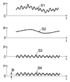
計器用変流器23は、風力発電装置2のパワーコンディショナ22から出力される交流電力を計測する。そして、図3に示すように、計器用変流器23は、この計測した信号S1を電力変換制御部31に入力する。
The instrument
電力変換制御部31は、風力発電装置2の発電電力のうちの高周波成分が、ヒータ5の駆動電力に変換されるように、インバータ電源回路24を備えた電力変換部33の動作を制御する。
The power
ここでは、電力変換制御部31は、図2に示すように、ハイパスフィルタ26、加算器29、及び関数器32を備えている。
Here, the power
電力変換制御部31のうち、ハイパスフィルタ26は、平滑化フィルタ27(ローパスフィルタ)と減算器28とを組み合わせることで構成されている。
In the power
ハイパスフィルタ26において、平滑化フィルタ27及び減算器28には、計器用変流器23から出力された信号S1が入力される。
In the
平滑化フィルタ27の出力は、図3に示すように、信号S1から高周波成分が除去された信号S2(低周波成分)が出力される。
As shown in FIG. 3, the output of the smoothing
減算器28は、図2、図3に示すように、信号S1から信号S2を減算した信号S3(差分信号)を出力する。
The
つまり、ハイパスフィルタ26(減算器28)は、計器用変流器23から入力された信号S1の高周波成分を出力する。ここで、ハイパスフィルタ26には、風力発電による発電電力のうちの前述した高周波成分(比較的速い出力変動成分)を抽出するために、この用途に対応した例えば1分よりも小さい時定数が設定されている。
That is, the high pass filter 26 (subtractor 28) outputs the high frequency component of the signal S1 input from the instrument
加算器29は、図2、図3に示すように、減算器28から出力された信号S3に、予め値が設定されたヒータ入力バイアスBを加算した信号S4を出力する。加算器29は、前述したインバータ電源回路24による制御を可能にするために、図3に示すように、信号S4は、基準電位(例えば0V)よりも低い負極成分が正極側の成分に移行するように、信号S3にヒータ入力バイアスBを加算して求められる。つまり、信号S4は、信号値が0よりも大きくなる。
As shown in FIGS. 2 and 3, the
関数器32は、図2に示すように、加算器29から信号S4が変数として入力される。そして、関数器32は、この入力された信号S4を、インバータ電源回路24側に対応する信号S5に変換(例えば信号のレベルなどを変更)する。そして、関数器32は、その変換された信号S5(関数)を出力する。
As shown in FIG. 2, the
電力変換部33において、インバータ電源回路24は、関数器32が出力した信号S5に基づいて、PWM制御を行う。これにより、インバータ電源回路24は、風力発電装置2のパワーコンディショナ22から出力された発電電力の高周波成分(出力変動成分)を、ヒータ5を駆動する駆動電力に変換する。そして、インバータ電源回路24から供給された駆動電力によって、ヒータ5が駆動する。これにより、熱媒循環流路10を流れる熱媒F2が加熱される。
In the power conversion unit 33, the inverter
このようにして加熱された熱媒F1の熱エネルギは、太陽熱発電装置3による発電のためのエネルギとして有効に活用される。一方、図2に示すように、風力発電装置2のパワーコンディショナ22から出力される発電電力から、高周波成分(出力変動成分)が除去されて平滑化された電力は、トランス25を介して、所定の電圧に昇圧された後、配電系統(電力系統)に送電される。
The heat energy of the heating medium F1 thus heated is effectively used as energy for power generation by the solar thermal
ここで、ハイパスフィルタ26の時定数について図4を参照して説明する。
Here, the time constant of the high-
図4は、ハイパスフィルタ26の時定数τ(発電電力の変動時間)と定格発電出力の調整可能幅との関係を示す図である。図4では、横軸が、時定数τ(発電電力の変動時間)を示し、縦軸が、定格発電出力の調整可能幅Xを示している。さらに、図4では、発電機ガバナ制御(発電機のロータ回転数のフィードバック制御)、LFC(Load Frequency Control/負荷周波数制御)、ELDC(Economic Load Dispatch Control)、及び再生可能エネルギを利用した発電を含む従来のハイブリッド制御(ハイブリッド発電制御)について、互いの特性を例示している。
FIG. 4 is a diagram showing the relationship between the time constant τ (the fluctuation time of generated power) of the high-
図4から判るように、本実施形態の発電システム1では、ハイパスフィルタ26の時定数τを1分よりも小さい値に設定することで、発電電力の変動成分の発生を抑えることができ、変動の少ない安定した発電電力を出力することができる。
As can be seen from FIG. 4, in the
以上のように、本実施形態の発電システム1では、風力発電装置2による発電電力の変動成分を、太陽熱発電装置3側での発電に用いる熱エネルギに変換する。このため、本実施形態においては、風力発電で得られる電力を有効に活用できると共に、変動が抑制され、安定した電力を出力することができる。また、本実施形態の発電システム1では、実質的に、ヒータ5を用いて、発電電力を平滑化させることができる。このため、本実施形態においては、耐久性に課題のある蓄電池を発電電力の平滑化に用いた場合と比べて、ランニングコストを低減させることができる。
As described above, in the
<第2実施形態>
第2実施形態について図5を参照して説明する。Second Embodiment
A second embodiment will be described with reference to FIG.
図5に示すように、本実施形態の発電システムは、第1の実施形態に係る発電システム1の構成に加え、熱媒F1の温度制御系として、温度センサ51、熱媒加熱制御部52、ミラー駆動部(第1の実施形態では図示せず)53をさらに備えている。
As shown in FIG. 5, in addition to the configuration of the
温度センサ51は、熱媒循環流路10を循環する熱媒F1の温度を検出する。温度センサ51は、熱媒循環流路10(図1参照)に設置されている。たとえば、温度センサ51は、熱媒循環流路10において、太陽熱集熱器7の下流側(後段側)や、ヒータ5の下流側などに配置されている。実質的には、温度センサ51は、熱媒循環流路10の全経路上において熱媒F1が最も高い温度になる位置に設置されている。温度センサ51は、熱媒循環流路10を構成する例えば配管の表面温度などを検出することによって、熱媒F1の温度を例えば間接的に検出する。この他に、温度センサ51を熱媒循環流路10に挿入して、直接、熱媒F1の温度を計測してもよい。
The
熱媒加熱制御部52は、温度センサ51の検出結果に基づいて、ミラー駆動部53及び熱媒移送ポンプ9の一方又は両方を制御する。詳述すると、熱媒加熱制御部52は、熱媒耐熱温度記憶部52a及び熱媒加熱状況予測部52bを備えている。
The heat medium
熱媒耐熱温度記憶部52aは、熱媒F1の耐熱温度(油としての物性を確保できる温度)を記憶している。
The heat medium heat resistant
熱媒加熱状況予測部52bは、温度センサ51が検出した熱媒F1の温度(最高温度)が、熱媒F1の耐熱温度に対して、例えば所定のマージンを確保した閾値の温度を、超えるか否かを予測(判定)する。
Whether the temperature (maximum temperature) of the heat medium F1 detected by the
温度センサ51で検出された熱媒F1の最高温度が、閾値を超えると予測された場合には、熱媒加熱制御部52は、太陽光を集光するミラー6の焦点位置がパイプ8の例えば中芯位置から外れるように、ミラー駆動部53を制御する。この他に、熱媒加熱制御部52は、熱媒循環流路10を循環する熱媒F1の移送速度が上昇するように熱媒移送ポンプ9の駆動を制御する。熱媒加熱制御部52は、ミラー駆動部53の制御と、熱媒移送ポンプ9の制御との一方を行なってもよく、両者を行なってもよい。これらの制御によって、熱媒加熱制御部52は、熱媒F1の温度上昇を抑制する。
When it is predicted that the maximum temperature of the heat medium F1 detected by the
したがって、本実施形態の発電システムによれば、第1の実施形態に係る発電システム1の効果に加え、過剰な加熱を抑制することができる。本実施形態では、熱媒F1が物性的に破壊されてしまうことなどを防止することが可能となる。
Therefore, according to the power generation system of the present embodiment, in addition to the effects of the
<第3実施形態>
図6は、第3実施形態に係る発電システムの構成を示す図である。<Third Embodiment>
FIG. 6 is a diagram illustrating a configuration of a power generation system according to the third embodiment.
図6に示すように、本実施形態の発電システム1は、風車の回転によって電力を発生する風力発電と、太陽熱集熱器7で集熱した熱によってパイプ8を含む熱媒循環流路10内を循環する熱媒F1を加熱し、その加熱した熱媒F1を発電に利用する太陽熱発電とを複合させた発電システムである。すなわち、発電システム1は、上記の実施形態の場合と同様に、風力発電装置2と太陽熱発電装置3とを接続したハイブリッド発電システムである。本実施形態において、上記の実施形態と重複する個所については、適宜、記載を省略する。なお、翼2aの枚数は、本実施形態に限り、説明の都合上、3枚としているが、これに限らない。
As shown in FIG. 6, the
本実施形態では、ナセル2bまたはタワー2cの内部には、ロータリエンコーダ(図示省略)が内蔵されている。ロータリエンコーダは、ロータの回転数を計測し、風車回転数Wrとして出力する。
In the present embodiment, a rotary encoder (not shown) is built in the
また、本実施形態では、ヒータ5は、例えば、発電制御装置600から供給される電力(ヒータ駆動電力Ph)により駆動される。
In the present embodiment, the
図7〜図9を参照して、発電制御装置600の詳細について説明する。
The details of the power
図7に示すように、発電制御装置600は、風のゆらぎフォロワー621(平滑電力信号生成部)と、タワーシャドウ効果オブザーバ622(タワーシャドウ効果電力生成部)と、短期変動電力抽出部626とを有する。
As shown in FIG. 7, the power
風のゆらぎフォロワー621は、風力発電装置2で計測された、ゆらぎを含む風力発電電力(以下「風車電力Pmessure」と称す)に対する2次の遅れフィルタである。ここでは、風のゆらぎフォロワー621が2次のフィルタであるとして説明をするが、これに限らない。風のゆらぎフォロワー621は、下記(式1)により風車電力Pmessureを平滑化することによって、平滑風力発電出力である平滑電力Pwd(平滑電力信号)を生成し出力する。
The
遅れフィルタは、例えば、ローパスフィルタなどで構成されている。遅れフィルタは、タワーシャドウ効果が生じないような時定数を持つ。具体的には、遅れフィルタは、例えば1秒〜60秒程度の時定数を有しており、この時定数で風力発電の発電出力を遅らせて平滑し出力する。 The delay filter is composed of, for example, a low-pass filter. The delay filter has a time constant that does not cause a tower shadow effect. Specifically, the delay filter has a time constant of about 1 second to 60 seconds, for example, and the power generation output of wind power generation is delayed and smoothed by this time constant and output.
タワーシャドウ効果オブザーバ622は、回転角観測部として、オブザーバ部623とタワーシャドウ効果電力計算部624とメモリ625とを有する。
The tower
タワーシャドウ効果オブザーバ622は、ロータリエンコーダを用いて測定した風車の回転数Wr、および、予め記憶されている風車の翼2aと風車を支持するタワー2c(塔)との関係を示す設計データ(羽根モデル)の両者を基に、回転する風車の翼2aのそれぞれがタワー2cを通過するときにトルクが減少するトルク減少量を求める。そして、タワーシャドウ効果オブザーバ622は、3枚の翼2aについて求めたトルクの減少量と、風のゆらぎフォロワー621により生成された平滑電力Pwdとから、タワーシャドウ効果電力Pshを生成する。
The tower
メモリ625は、風力発電設備のデータと計算式(式1〜式4等)とを記憶している。メモリ625は、風力発電設備のデータとして、例えば、風車の翼2a、風車を支持するタワー2c、翼2aの回転で生じるトルク、翼2aの回転で生じる発電電力などの設計データを記憶している。設計データは、例えば、風車の翼2aと風車を支持するタワー2cとの位置関係を示すデータ、および、風車の翼2aの回転を模擬するプログラムである羽根モデルなども含む。羽根モデルは、回転する翼2aが回転軸に沿った方向においてタワー2cに重なったときにトルクが減少し、発電出力が減少する仕組みを模擬するものである。
The memory 625 stores wind power generation facility data and calculation formulas (
オブザーバ部623は、計測された風車電力Pmessureと風車の回転数Wrを用いて、風車の翼2aの回転角δを計算(推定)する。例えば、タワー2cの立つ方向(垂直方向)または水平方向を0°としたときに、翼2aが回転した角度を、翼2aの回転角δとして求める。
The
タワーシャドウ効果電力計算部624は、オブザーバ部623により計算された回転角δと、風のゆらぎフォロワー621から得られた平滑電力Pwdとから、タワーシャドウ効果による電力であるタワーシャドウ効果電力Pshを計算(推定)する。
The tower shadow effect
詳細には、タワーシャドウ効果電力計算部624は、風車の翼2aがタワー2cの陰になるタイミング(時点)を計算する。そして、タワーシャドウ効果電力計算部624は、その計算したタイミングでのトルクの減少を計算し、その計算したトルクの減少による発電量の減少量を計算する。
Specifically, the tower shadow effect
タワーシャドウ効果電力計算部624は、タワーシャドウ効果電力Pshの計算にあたり、まず、風車の3枚の翼2aのそれぞれが、タワー2cの位置を通過することに起因する電力の減少幅を計算(推定)する。
In calculating the tower shadow effect power Psh, the tower shadow effect
回転する風車の翼2aがタワー2cを通過したときに、パワーが減少する、パワーの減少幅は、余弦関数(cosθ)によって表される。
When the
また、風力発電の発電量は、各翼2aのそれぞれを用いて発生する電力の合計値Ptwとして、下記(式2)によって、近似できる。
Further, the power generation amount of wind power generation can be approximated by the following (Equation 2) as the total value Ptw of power generated using each of the
ここで、εは、タワー2cの幅であり、δは、風車を構成する一枚の翼2aの回転角であり、Twindは、風車のトルクであり、ωは、回転角速度である。回転角δは、下記(式A)のように、表すことができる。
Here, ε is the width of the
なお上記(式2)のδ’、δ’’は、風車を構成する他の翼2aの回転角である。3枚の翼2aは、回転方向において等間隔に配置されている。このため、δ’、δ’’のそれぞれは、δに対して、120度、240度、減算した角度になる。また、εは、タワーシャドウ効果が及ぶ範囲、つまりタワー2cの幅を示し、タワー2cの太さにより決まるパラメータである。
Note that δ ′ and δ ″ in the above (Equation 2) are rotation angles of the
(式2)中の各括弧内において、上段部分(「(1−cos(δ/ε))」等が記載された部分)は、翼2aがタワー2cを通過する時間帯の場合を示している。そして、下段部分(「1...other wise」が記載された部分)は、翼2aがタワー2cを通過する時間帯以外の時間帯の場合を示している。(式2)から判るように、翼2aがタワー2cを通過する時間帯では発電出力が減少するのに対して、その他の時間帯では発電出力が不変である。
In each parenthesis in (Formula 2), the upper part (the part where “(1-cos (δ / ε))” etc. is described) indicates the time zone in which the
具体的には、翼2aがタワー2cを通過する時間帯では、(式2)の各括弧内において上段部分に記載したように、各翼2aの回転角δ、δ’、δ’’の絶対値は、((π/2)ε)で示す値よりも小さく、括弧内の値は、(1−cos(δ/ε)),(1−cos(δ’/ε)),(1−cos(δ’’/ε))になる。これに対して、翼2aがタワー2cを通過する時間帯以外の時間帯においては、(式2)の各括弧内において「1...other wise」と下段部分に記載しているように、括弧内の値は、「1」である。これは、各翼2aがタワー2cの端部を通過するときには、各翼2aの回転角δ、δ’、δ’’は、(π/2)εとなるので、括弧内において、cos(δ/ε)、cos(δ’/ε)、cos(δ’’/ε)の値は、0になるからである(つまり、δ=δ’=δ’’=(π/2)εであり、cos(δ/ε)=cos(δ’/ε)=cos(δ’’/ε)=0である)。すなわち、翼2aがタワー2cを通過する時間帯以外の時間帯では、タワーシャドー効果は、出現しない。
Specifically, in the time zone in which the
(式2)に示す風力発電の発電量のうち、タワーシャドウ効果によって減少する電力の減少量は、下記の(式3)より計算(推定)することができる。 Of the power generation amount of the wind power generation shown in (Formula 2), the power reduction amount due to the tower shadow effect can be calculated (estimated) from the following (Formula 3).
(式3)に示すように、タワーシャドウ効果は、右辺に含まれる3個の関数の和により、近似的に求めることができる。これを図示すると、図8のようになる。(式3)においても、(式2)と同様に、各括弧内において、上段部分は、翼2aがタワー2cを通過する時間帯の場合を示しており、下段部分は、翼2aがタワー2cを通過する時間帯以外の時間帯の場合を示している。なお、式(2)は、タワーシャドウ効果が出現しない本来の発電量から、式(3)に示すタワーシャドウ効果による発電量の減少分を、差し引いたものに相当する。
As shown in (Expression 3), the tower shadow effect can be approximately obtained by the sum of three functions included in the right side. This is illustrated in FIG. In (Equation 3), as in (Equation 2), in each parenthesis, the upper part indicates the time zone in which the
次に、オブザーバ部623による風車(翼2a)の回転角δ、δ’、δ’’の計算動作(推定処理)を説明する。
Next, the calculation operation (estimation process) of the rotation angles δ, δ ′, δ ″ of the windmill (
上述したように、一枚の翼2aの回転角δを計算(推定)できれば、他の二枚の翼2aの回転角δ’、δ’’は、回転角δに対して120度、240度ずらすことで容易に計算できる。
As described above, if the rotation angle δ of one
オブザーバ部623は、回転角δを計算(推定)するにあたり、図9に示すように、測定した風車電力Pmessureにおいて、例えば1秒程度の周期を中心とする電力のゆれ信号を、バンドパスフィルタまたはハイパスフィルタを通過させることによって、短期の変動成分を生成する。
In calculating (estimating) the rotation angle δ, the
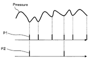
そして、オブザーバ部623は、その得られた短期の変動成分を用いて、タワーシャドウ効果により電力が下がる方向へ揺らぐ箇所をピークカウンタによりカウントし、ピークカウンタ出力パルスP1を得る。
Then, the
そして、オブザーバ部623は、ピークカウンタによりカウントされた3パルスごとに、δカウンタで1パルスをカウントし、δカウンタ出力パルスP2を得ることによって、翼2aがタワーを通過するタイミングを抽出する。
Then, the
δカウンタから出力されるδカウンタ出力パルスP2の発生の瞬間が、δ=0を通過した瞬間に相当する。 The moment when the δ counter output pulse P2 output from the δ counter is generated corresponds to the moment when δ = 0 is passed.
そこで、回転角δは、下記(式4)に示すように、δ=0を通過した瞬間から風車の回転数Wrから導き出した風車の角速度ω(計測値)を積分することによって、計算(推定)される。 Therefore, as shown in the following (Equation 4), the rotation angle δ is calculated (estimated) by integrating the wind turbine angular velocity ω (measured value) derived from the wind turbine rotation speed Wr from the moment when δ = 0. )
短期変動電力抽出部626は、包絡線生成部627、短期変動成分分離部628、制御部629、インバータ630(以下「INV630」と称す)などを有する。この短期変動電力抽出部626は、風車電力Pmessureから短期変動成分の電力を抽出する。
The short-term fluctuation
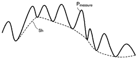
包絡線生成部627は、タワーシャドウ効果オブザーバ622から出力されたタワーシャドウ効果電力Pshと、風のゆらぎフォロワー621から出力された平滑出力Pwdとを基に、短期間に上下に変動する風車電力Pmessureの下限値(極小値)を結ぶ包絡線Shを生成する。
The
具体的には、包絡線生成部627は、タワーシャドウ効果電力Pshを元々の風車電力Pmessureに加えて電力信号を得る。そして、包絡線生成部627は、その得られた電力信号から、タワーシャドウ効果電力Pshの振幅を差し引くことによって、包絡線Shを生成する。
Specifically, the
すなわち、包絡線Shは、風のゆらぎフォロワー621から出力された平滑出力Pwdから、タワーシャドウ効果電力Pshの振幅の半分を引いた値によって求められる。このようにして算出された包絡線Shよりも大きな風力発電電力が、平滑すべき短期出力変動である。
That is, the envelope Sh is obtained by a value obtained by subtracting half of the amplitude of the tower shadow effect power Psh from the smooth output Pwd output from the
短期変動成分分離部628は、包絡線生成部627により生成された包絡線Shを用いて、風車電力Pmessureから短期変動成分を分離する。
The short-term fluctuation
INV630は、短期変動成分分離部628により分離された短期変動成分を、ヒータ駆動電力Phに変換し、その変換したヒータ駆動電力Phをヒータ5へ供給する。これにより、ヒータ5が駆動して、熱媒循環経路10を流れる熱媒F1が加熱される。
The
制御部629は、ヒータ5およびINV630の駆動を制御する。
The control unit 629 controls driving of the
より具体的には、制御部629は、太陽熱集熱器7のパイプ8、または、熱媒循環経路10を流れる熱媒F1の温度を、温度計(図示省略)により検出する。そして、制御部629は、熱媒F1の温度が、予め設定しておいたしきい値を超えた場合に、ヒータ制御信号Hcによりヒータ5の駆動を停止する。制御部629は、熱媒F1の温度がしきい値を超えた場合に、INV630の駆動を停止するように制御してもよい。また、パイプ8を含む熱媒循環経路10を流れる熱媒F1の温度を制限するために、制御部629は、例えば太陽熱集熱器7のミラー駆動部(図示省略)を駆動して、ミラー8の焦点をずらす制御を行ってもよい。
More specifically, the control unit 629 detects the temperature of the heat medium F1 flowing through the
以下、図10,図11を参照して、本実施形態の動作を説明する。 The operation of this embodiment will be described below with reference to FIGS.
本実施形態では、発電制御装置600において、タワーシャドウ効果オブザーバ622と風のゆらぎフォロワー621が、風力発電装置2の動作状態を監視しており、風力発電で生じる各種データ(風車電力Pmessure、風車の回転数Wrなど)を検出(取得)する(図10のステップS101)。
In the present embodiment, in the power
風のゆらぎフォロワー621は、取得した風車電力Pmessureを平滑化し平滑電力Pwdを生成し、短期変動電力抽出部626とタワーシャドウ効果オブザーバ622へ出力する(ステップS102)。
The
タワーシャドウ効果オブザーバ622では、風車の回転数Wrをオブザーバ部623が取得して、タワーシャドウ効果電力計算部624に出力する。
In the tower
タワーシャドウ効果電力計算部624は、風のゆらぎフォロワー621から入力された平滑電力Pwdと、オブザーバ部623からの風車の回転数Wrとメモリ625のデータ(羽根モデル、計算式など)を用いて、タワーシャドウ効果電力Pshを計算し(ステップS103)、短期変動電力抽出部626へ出力する。
The tower shadow effect
短期変動電力抽出部626では、包絡線生成部627が、風のゆらぎフォロワー621から入力された平滑電力Pwdと、タワーシャドウ効果オブザーバ622から入力されたタワーシャドウ効果電力Pshとから、図11に示すように、風車電力Pmessureの包絡線Shを生成し(ステップS104)、短期変動成分分離部628へ出力する。
In the short-term fluctuation
短期変動成分分離部628は、包絡線生成部627から入力された包絡線Shにて、ゆらぎのある風車電力Pmessureから短期の変動成分を分離し(ステップS105)、分離した短期の変動成分をINV630へ出力する。
The short-term fluctuation
INV630は短期の変動成分をヒータ駆動電力Phに変換し(ステップS106)、ヒータ5へ供給する。
The
以上のように、本実施形態によれば、風力発電装置2の翼2aがタワー2cに差し掛かってトルクが減少するタワーシャドウ効果を加味して、風力発電電力の短期のゆらぎ成分を高精度に計算する。そして風力発電電力から短期のゆらぎ成分を分離して他の電力設備(ヒータ5など)へ供給する。これにより、風力発電で得られた電力を効率よく利用することができる。
As described above, according to the present embodiment, the short-term fluctuation component of the wind power generation is calculated with high accuracy in consideration of the tower shadow effect in which the
また、本実施形態では、太陽熱発電と風力発電とをハイブリット化しており、従来カットしていた風力発電電力の高周波成分(風力発電の数秒程度以下の早い出力変動成分)を太陽熱発電装置に供給している。このためより大きな電力を発生させることができ、発電システム全体としての発電効率の向上を図ることができる。 Moreover, in this embodiment, solar power generation and wind power generation are hybridized, and high-frequency components of wind power generation that have been cut in the past (fast output fluctuation components of about several seconds or less of wind power generation) are supplied to the solar power generation device. ing. For this reason, more electric power can be generated and the power generation efficiency of the power generation system as a whole can be improved.
さらにヒータ5などの設備は、蓄電池に比べて劣化し難く、初期コストおよびメンテナンスコストが低いので、蓄電池を利用する場合よりも設備の低コスト化を実現することができる。
Furthermore, the equipment such as the
この結果、風力発電および太陽熱発電などの自然エネルギ(再生可能エネルギ)により発電する場合に、蓄電池を用いずに、低コスト、かつ、効率よく発電することができる。 As a result, when generating power by natural energy (renewable energy) such as wind power generation and solar thermal power generation, it is possible to generate power efficiently and at low cost without using a storage battery.
<第4実施形態>
[A]全体構成
図12は、第4実施形態に係る発電システムの概念を示す概念図である。<Fourth embodiment>
[A] Overall Configuration FIG. 12 is a conceptual diagram showing the concept of the power generation system according to the fourth embodiment.
発電システム1は、図12に示すように、風力発電装置2、太陽熱発電装置3、インバータ40、出力制御装置50、及び制御装置100を備えている。以下より、発電システム1を構成する各部について、順次、説明する。
As shown in FIG. 12, the
[A−1]風力発電装置2
風力発電装置2は、プロペラ型の風車を含み、図12に示すように、ロータ21aと発電機21とパワーコンディショナ22とを備えている。[A-1]
The
風力発電装置2のうち、ロータ21aは、ハブ211と複数のブレード212(翼)とシャフト213とを有する。ロータ21aは、ハブ211を中心にして複数のブレード212が回転方向において等間隔に設置されている。そして、ハブ211にシャフト213の一端が固定されている。ロータ21aは、シャフト213を回転軸として回転する。図示を省略しているが、ロータ21aは、タワーの上端部に設置されたナセルに回転可能に支持されている。風力発電装置2は、プロペラ風車を含む。
Of the
風力発電装置2のうち、発電機21は、ロータ21aのシャフト213に連結されており、シャフト213の回転によって駆動し、発電を行う。
In the
風力発電装置2のうち、パワーコンディショナ22は、発電機21に電気的に接続されている。パワーコンディショナ22は、発電機21が出力した電力について周波数を変換して、第1送電線200へ出力する。
In the
そして、風力発電装置2では、発電機21からパワーコンディショナ22を介して出力された電力E1(第1電力)のデータがカレントトランスフォーマ23を用いて検出され、その検出されたデータが風力発電出力信号Sαとして制御装置100へ出力される。
In the
また、風力発電装置2が出力した電力E1のうち、一部の電力E12が第1送電線200から太陽熱発電装置3に出力され、その他の部分の電力E11が変圧器25(トランス)を介して第1送電線200から電力系統(交流電力系統)に出力される。
Further, out of the electric power E1 output by the
[A−2]太陽熱発電装置3
太陽熱発電装置3は、たとえば、パラボリック・トラフ式であり、図12に示すように、集熱部3Aと発電部3Bとを含む。[A-2] Solar thermal
The solar thermal
太陽熱発電装置3のうち、集熱部3Aは、図12に示すように、第1配管131、曲面ミラー132、ヒータ133、熱交換器134、及び第1ポンプ135を有し、太陽熱を集熱することによって熱媒F1を加熱する。
As shown in FIG. 12, the
具体的には、集熱部3Aでは、熱媒F1は、第1配管131の内部を流れる。熱媒F1は、曲面ミラー132が第1配管131に集光した太陽光によって集熱された熱で加熱される。これと共に、熱媒F1は、ヒータ133によって更に加熱される。その後、加熱された熱媒F1は、熱交換器134に流入する。そして、熱媒F1は、第1ポンプ135から吐出される。このようにして、熱媒F1は、第1配管131の内部を循環する。
Specifically, in the
図示を省略しているが、集熱部3Aにおいては、曲面ミラー132を回転移動させるアクチュエータが設置されている。そのアクチュエータは、制御装置100から出力された制御信号(図示省略)に応じて曲面ミラー132を回転させることによって、曲面ミラー132の集光面と太陽との間の相対角度を変更する。たとえば、熱媒F1の温度に基づいて算出された制御信号に応じて、曲面ミラー132が回転移動されることによって、熱媒F1の温度が制御される。
Although not shown, an actuator that rotates and moves the
太陽熱発電装置3のうち、発電部3Bは、図12に示すように、第2配管301、タービン302、発電機303、凝縮器304、冷却塔305、第2ポンプ306、第3ポンプ307、及び蒸気弁308を有し、熱媒F1との間で熱交換がされた作動流体F2によって発電を行う。
Among the solar thermal
具体的には、発電部3Bでは、作動流体F2は、第2配管301の内部を流れる。作動流体F2は、熱交換器134において熱媒F1との間で熱交換がされ、加熱される。そして、その加熱された作動流体F2は、蒸気弁308を介して、タービン302の内部に流入し、タービンロータ(図示省略)が回転する。そして、このタービンロータの回転によって、発電機303が発電を行う。そして、発電機303から電力E2(第2電力)が第2送電線300を介して電力系統に出力される。そして、作動流体F2は、タービン302から排出された後に、凝縮器304で凝縮される。凝縮器304では、冷却塔305で冷却された冷却媒体が第2ポンプ306によって供給され、その冷却媒体によって作動流体F2が凝縮する。そして、凝縮された作動流体F2は、第3ポンプ307から吐出されることによって、第2配管301の内部を循環する。
Specifically, in the
太陽熱発電装置3は、上記のように発電を行うため、入熱から発電までの間に、数分程度の時間を要する。
Since the solar thermal
[A−3]インバータ40,出力制御装置50
インバータ40は、半導体変換器であって、制御装置100が出力した制御信号に基づいて動作する。出力制御装置50は、発電部3Bの出力を制御する。[A-3]
The
具体的には、インバータ40は、制御装置100から第1制御信号S10が入力される。インバータ40は、第1制御信号S10に応じて、風力発電装置2が出力した電力E1について周波数を変換することによって、風力発電装置2が出力した電力E1のうち、一部の電力E12を第1送電線200からヒータ133に出力する。
Specifically, the
また、出力制御装置50は、制御装置100から第2制御信号S20が入力される。出力制御装置50は、第2制御信号S20に応じて、太陽熱発電装置3の発電機303の出力を主蒸気弁308により調整する。つまり、出力制御装置50は、第2制御信号S20に基づいて、主蒸気弁308の開度を調整することによって、発電機303が出力する電力E2の量を調整する。太陽熱発電装置3の発電機303が出力した電力E2は、第2送電線300から変圧器321に出力される。
Further, the
そして、この電力E2は、変圧器321を介して第1送電線200に出力され、風力発電装置2が出力した電力E1において一部の電力E12が差分された電力E11に合成される。
And this electric power E2 is output to the 1st
[A−4]制御装置100
制御装置100は、図12に示すように、カレントトランスフォーマ23(ポテンシャルトランスフォーマ)から風力発電出力信号Sαが入力される。そして、制御装置100は、風力発電出力信号Sαに基づいて、第1制御信号S10をインバータ40に出力する。これと共に、制御装置100は、風力発電出力信号Sαに基づいて、第2制御信号S20を出力制御装置50に出力する。[A-4]
As shown in FIG. 12, the
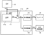
図13は、第4実施形態に係る発電システムにおいて、制御装置、及び、制御装置との間においてデータの入出力を行う部材を示すブロック図である。 FIG. 13: is a block diagram which shows the member which inputs / outputs data between control apparatuses and a control apparatus in the electric power generation system which concerns on 4th Embodiment.
図13に示すように、制御装置100は、ハイパスフィルタ111と、第1関数器112(第1制御信号算出部)と、第2関数器120(第2制御信号算出部)とを有する。
As illustrated in FIG. 13, the
[A−4−1]ハイパスフィルタ111
制御装置100のうち、ハイパスフィルタ111は、図13に示すように、カレントトランスフォーマ23から風力発電出力信号Sαが入力される。そして、ハイパスフィルタ111は、その風力発電出力信号Sαについてハイパスフィルタリング処理を行い、風力発電出力信号Sαに含まれる高周波成分信号S1を抽出して出力する。[A-4-1] High-
In the
具体的には、ハイパスフィルタ111は、図13に示すように、ローパスフィルタ111aと加減算器111bとを含む。ローパスフィルタ111aは、風力発電出力信号Sαについてローパスフィルタリング処理を行うことによって、風力発電出力信号Sαに含まれる低周波成分信号S1aを算出する。そして、加減算器111bは、風力発電出力信号Sαから低周波成分信号S1aを減算する処理を行う。このようにして、ハイパスフィルタ111は、高周波成分信号S1を算出する。ハイパスフィルタ111は、上記の実施形態で示した場合と同様に、時定数が1分よりも小さいことが好ましい。
Specifically, as shown in FIG. 13, the
[A−4−2]第1関数器112
制御装置100のうち、第1関数器112は、図13に示すように、ハイパスフィルタ111から高周波成分信号S1が入力される。そして、第1関数器112は、予め記憶している関数を用いて、入力された高周波成分信号S1から第1制御信号S10を算出する処理を行い、その第1制御信号S10をインバータ40に出力する。[A-4-2]
In the
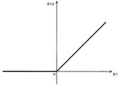
図14は、第4実施形態に係る発電システムにおいて、第1関数器で用いる関数を示す図である。 FIG. 14 is a diagram illustrating functions used in the first function unit in the power generation system according to the fourth embodiment.
図14においては、横軸が、第1関数器112に入力される高周波成分信号S1の値を示している。そして、縦軸が、第1関数器112から出力される第1制御信号S10の値を示している。
In FIG. 14, the horizontal axis indicates the value of the high frequency component signal S <b> 1 input to the
第1関数器112は、図14に示すように、入力された高周波成分信号S1の値がゼロ以上(正)の場合には、出力する第1制御信号S10の値を、その高周波成分信号S1の絶対値に比例して増加させる(S1≧0のとき、たとえば、S10=S1)。一方で、入力された高周波成分信号S1の値が、ゼロ未満(負)の場合には、その高周波成分信号S1の値に関わらずに、出力する第1制御信号S10の値をゼロにする(S1<0のとき、S10=0・S1)。
As shown in FIG. 14, when the value of the input high frequency component signal S1 is zero or more (positive), the
このように、本実施形態では、第1関数器112は、第1制御信号算出部であって、高周波成分信号S1のうち正成分を抽出することによって第1制御信号S10を算出する。
Thus, in the present embodiment, the
なお、第1関数器112を用いずに、複数の加減算器を用いて複数の信号について加算処理または減算処理を行うことによって、第1制御信号S10を算出してもよい。
Note that the first control signal S10 may be calculated by performing addition processing or subtraction processing on a plurality of signals using a plurality of adders / subtracters without using the
[A−4−3]第2関数器120
制御装置100のうち、第2関数器120は、図13に示すように、ハイパスフィルタ111から高周波成分信号S1が入力される。そして、第2関数器120は、予め記憶している関数を用いて、入力された高周波成分信号S1から第2制御信号S20を算出し、その第2制御信号S20を出力制御装置50に出力する。[A-4-3]
In the
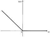
図15は、第4実施形態に係る発電システムにおいて、第2関数器で用いる関数を示す図である。 FIG. 15 is a diagram illustrating functions used in the second function unit in the power generation system according to the fourth embodiment.
図15においては、横軸が、第2関数器120に入力される高周波成分信号S1の値を示している。そして、縦軸が、第2関数器120から出力される第2制御信号S20の値を示している。
In FIG. 15, the horizontal axis indicates the value of the high frequency component signal S <b> 1 input to the
第2関数器120は、図15に示すように、入力された高周波成分信号S1の値がゼロ以上(正)の場合には、出力する第2制御信号S20の値を、その高周波成分信号S1の値に関わらずに、ゼロにする(S1≧0のとき、たとえば、S20=0・S1とする)。一方で、入力された高周波成分信号S1の値がゼロ未満(負)の場合には、出力する第2制御信号S20の値を、その高周波成分信号S1の絶対値に比例して増加させる(S1<0のとき、たとえば、S20=−S1とする)。
As shown in FIG. 15, when the value of the input high frequency component signal S1 is zero or more (positive), the
このように、本実施形態では、第2関数器120は、第2制御信号算出部であって、高周波成分信号S1のうち負成分を抽出することによって第2制御信号S20を算出する。
Thus, in the present embodiment, the
なお、第2関数器120では、高周波成分信号S1のうち負成分を抽出するデータに対して、さらに一定値をバイアスとして加算したものを、第2制御信号S20として出力制御装置50に出力してもよい(つまり、S1≧0のとき、たとえば、S20=0・S1+b1とし、S1<0のとき、たとえば、S20=−S1+b1(b1≧0,図15では、b1=0)としてもよい)。この場合、第1関数器112では、これに対応して、S1−b1>0のとき、S10=S1−b1とし、S1−b1<0の時には、S10=0とする。
In the
また、第2関数器120を用いずに、複数の加減算器を用いて複数の信号について加算処理または減算処理を行うことによって、第2制御信号S10を算出してもよい。
Further, the second control signal S10 may be calculated by performing addition processing or subtraction processing on a plurality of signals using a plurality of adders / subtracters without using the
上記の制御装置100については、上記の各部の機能をプログラムがコンピュータに実現させるように構成してもよい。
The
[B]動作
図16A,図16B,図16C,図17A,図17Bは、第4実施形態に係る発電システムにおいて、制御装置で用いられるデータを示す図である。[B] Operation FIGS. 16A, 16B, 16C, 17A, and 17B are diagrams illustrating data used in the control device in the power generation system according to the fourth embodiment.
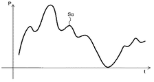
図16Aは、風力発電出力信号Sαを示し、図16Bは、ハイパスフィルタ111を構成するローパスフィルタ111aが出力する低周波成分信号S1aを示し、図16Cは、ハイパスフィルタ111を構成する加減算器111bが出力する高周波成分信号S1を示している。また、図17Aは、第1制御信号S10を示し、図17Bは、第2制御信号S20を示している。各図では、横軸が時間tであり、縦軸がデータ値Pである。
16A shows the wind power generation output signal Sα, FIG. 16B shows the low-frequency component signal S1a output from the low-
以下より、図13に示した制御装置100の動作について、図16A,図16B,図16C,図17A,図17Bを用いて詳細に説明する。
Hereinafter, the operation of the
まず、図13に示すように、制御装置100では、ハイパスフィルタ111を構成するローパスフィルタ111aに風力発電出力信号Sαが入力される。風力発電出力信号Sαは、風力の変動などの要因によって、図16Aに示すように、時間tに応じてデータ値Pが大きく揺らいでいる。
First, as shown in FIG. 13, in the
つぎに、図13に示すように、風力発電出力信号Sαについてローパスフィルタ111aがローパスフィルタリング処理を行うことによって、低周波成分信号S1aを算出する。低周波成分信号S1aは、図16Bに示すように、風力発電出力信号Sα(図16A参照)に含まれる低周波成分に相当する。
Next, as shown in FIG. 13, the low-
つぎに、図13に示すように、ローパスフィルタ111aが出力した低周波成分信号S1aと、風力発電出力信号Sαとから、加減算器111bが高周波成分信号S1を算出する。図16Cに示すように、高周波成分信号S1は、風力発電出力信号Sα(図16A参照)から低周波成分信号S1a(図16B参照)が減算されたものであって(S1=Sα−S1a)、風力発電出力信号Sαに含まれる高周波成分である。
Next, as shown in FIG. 13, the adder /
つぎに、図13に示すように、ハイパスフィルタ111が出力した高周波成分信号S1から第1関数器112が第1制御信号S10を算出する。図17Aに示すように、第1制御信号S10は、高周波成分信号S1(図16C参照)のうち、正成分について抽出されたデータに相当する。
Next, as shown in FIG. 13, the
これと共に、図13に示すように、ハイパスフィルタ111が出力した高周波成分信号S1から第2関数器120が第2制御信号S20を算出する。図17Bに示すように、第2制御信号S20は、高周波成分信号S1(図16C参照)のうち、負成分について抽出した後に、その抽出したデータについて符号を反転させたデータに相当する。換言すると、第2制御信号S20は、高周波成分信号S1(図16C参照)から、第1制御信号S10(図17A参照)を減算することによって高周波成分信号S1の負成分について抽出した後に、その高周波成分信号S1の負成分について正負を反転させた信号である。
At the same time, as shown in FIG. 13, the
図13に示すように、上記のように算出された第1制御信号S10は、インバータ40に出力される。このとき、図12に示すように、インバータ40では、第1制御信号S10の信号値に応じて、風力発電装置2が出力する電力E1のうち一部の電力E12を第1送電線200からヒータ133に出力する。そして、その出力された電力E12によってヒータ133が発熱し、第1配管131の内部を流れる熱媒F1を加熱する。
As shown in FIG. 13, the first control signal S <b> 10 calculated as described above is output to the
具体的には、図17Aに示すように、第1制御信号S10がゼロを超えた部分であるときに、風力発電装置2が出力する電力E1のうち一部の電力E12を、ヒータ133に出力する。一方で、第1制御信号S10がゼロであるときには、電力E12をヒータ133に出力しない。
Specifically, as shown in FIG. 17A, when the first control signal S10 is a part where the value exceeds zero, a part of the electric power E12 output from the
また、図13に示すように、上記のように算出された第2制御信号S20は、出力制御装置50に出力される。このとき、図12に示すように、出力制御装置50は、第2制御信号S20の信号値に応じて、主蒸気弁308の開度を調整し、タービン302に流入する作動流体F2の量を調整する。ここでは、第2制御信号S20の信号値が大きくなるに伴って、主蒸気弁308の開度が大きくなるように調整される。これにより、太陽熱発電装置3が発電して第2送電線300に出力する電力E2の量が、調整される。そして、その出力が調整された電力E2が、第1送電線200に出力される。この電力E2は、風力発電装置2が出力する電力E1から、ヒータ133へ出力された一部の電力E12が差分された電力E11に合成されて、電力系統に出力される。
As shown in FIG. 13, the second control signal S20 calculated as described above is output to the
具体的には、図17Bに示すように、第2制御信号S20がゼロを超えた部分であるときには、第2制御信号S20の信号値に応じて主蒸気弁308の開度が所定の基準値よりも大きくなるように、出力制御装置50が主蒸気弁308の開度を調整する。一方で、第2制御信号S20がゼロあるときには、主蒸気弁308の開度を所定の基準値に保持させる。
Specifically, as shown in FIG. 17B, when the second control signal S20 exceeds zero, the opening of the
なお、第2制御信号S20に対してバイアスを加えた信号を出力制御装置50に出力した場合には、そのバイアスの値に応じて、電力E2を更に補充することになる。
In addition, when the signal which added the bias with respect to 2nd control signal S20 is output to the
図18A,図18B,図18Cは、第4実施形態に係る発電システムにおいて、風力発電装置から電力系統へ出力される電力に関するデータを示す図である。 FIG. 18A, FIG. 18B, and FIG. 18C are diagrams showing data related to the power output from the wind turbine generator to the power system in the power generation system according to the fourth embodiment.
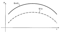
図18Aは、図16Aと同様に、電力E1(図12参照)に関する風力発電出力信号Sαを示している。図18Bは、電力E11(E11=E1−E12)(図12参照)に関する風力発電出力信号Sα1について示している。図18Cは、電力E3(E3=E11+E2)(図12参照)に関する風力発電出力信号Sα2について示している。図18A,図18B,図18Cでは、ローパスフィルタ111aが出力した低周波成分信号S1a(図16B参照)を重ねて示している。
FIG. 18A shows the wind power generation output signal Sα related to the power E1 (see FIG. 12), similarly to FIG. 16A. FIG. 18B shows the wind power generation output signal Sα1 related to the power E11 (E11 = E1-E12) (see FIG. 12). FIG. 18C shows the wind power generation output signal Sα2 related to the power E3 (E3 = E11 + E2) (see FIG. 12). In FIG. 18A, FIG. 18B, and FIG. 18C, the low-frequency component signal S1a (see FIG. 16B) output from the low-
以下より、図12に示した発電システム1において、風力発電装置2から第1送電線200を介して電力系統へ出力される電力について、図18A,図18B,図18Cを用いて詳細に説明する。
Hereinafter, in the
図12に示すように、風力発電装置2が出力した電力E11は、図18Aに示す風力発電出力信号Sαのように、風力の変動などの要因によって、データ値Pが大きく揺らいでいる。
As shown in FIG. 12, the electric power E11 output from the
そして、図12に示すように、制御装置100から第1制御信号S10がインバータ40に出力された場合は、風力発電装置2が出力した電力E1のうち、一部の電力E12が、インバータ40を介して、第1送電線200からヒータ133に出力される。この電力E12は、風力発電出力信号Sα(図18A参照)のうち、低周波成分信号S1aより大きい正成分Sα(+)の絶対値に相当する。
Then, as shown in FIG. 12, when the first control signal S <b> 10 is output from the
このため、図12に示すように、一部の電力E12がヒータ133に出力された後の電力E11は、図18Bに示す風力発電出力信号Sα1のように、風力発電出力信号Sα(図18A参照)のうち、低周波成分信号S1aより大きい正成分Sα(+)がカットされた状態になる。つまり、風力発電出力信号Sαにおいて、ローパスフィルタ111aが出力した低周波成分信号S1aより大きい正成分Sα(+)の部分が、平滑化された状態になる。
Therefore, as shown in FIG. 12, the electric power E11 after a part of the electric power E12 is output to the
そして、図12に示すように、第2制御信号S20が出力制御装置50に出力された場合には、主蒸気弁308の開度が調整されることによって、電力E2の調整が行われる。そして、その調整された電力E2が、太陽熱発電装置3から第1送電線200に出力されて、合成される。この電力E2は、風力発電出力信号Sα(図18A参照)のうち、低周波成分信号S1aより小さい負成分Sα(−)の絶対値が、低周波成分信号S1aに加算された形状になる。
And as shown in FIG. 12, when 2nd control signal S20 is output to the
このため、図12に示すように、電力E2が合成された後の電力E3は、図18Cに示す風力発電出力信号Sα2のように、ローパスフィルタ111aが出力した低周波成分信号S1aと同様な状態になる。つまり、電力E3は、風力発電出力信号Sα(図18A参照)のうち、低周波成分信号S1aより大きい正成分Sα(+)がカットされると共に、低周波成分信号S1aより小さい負成分Sα(−)が加えられた状態になる。
Therefore, as shown in FIG. 12, the electric power E3 after the electric power E2 is combined is in the same state as the low-frequency component signal S1a output from the low-
このようにして、風力発電装置2から第1送電線200を介して電力系統へ最終的に出力される電力E3は、平滑化され、揺らぎが低減された状態になる。
In this way, the electric power E3 that is finally output from the
[C]まとめ
以上のように、本実施形態の発電システム1では、風力発電装置2において、風力によって発電した電力E1(第1電力)が第1送電線200に出力される。この他に、太陽熱発電装置3では、太陽熱及びヒータ133で加熱された熱媒F1と熱交換がされた作動流体F2によって発電された電力E2(第2電力)が、第2送電線300に出力される。このとき、本実施形態では、風力発電装置2が出力した電力E1のうち、一部の電力E12を、インバータ40が第1制御信号S10に応じてヒータ133に出力する。これと共に、出力制御装置50が、第2制御信号S20に応じて、太陽熱発電装置3が出力する電力E2を調整し、第2送電線300を介して、第1送電線200に出力する。制御装置100は、電力E1に応じて得られた風力発電出力信号Sαに基づいて、第1制御信号S10をインバータ40に出力すると共に、第2制御信号S20を出力制御装置50に出力する。具体的には、制御装置100は、ハイパスフィルタ111が風力発電出力信号Sαに含まれる高周波成分信号S1を抽出する。そして、第1関数器112(第1制御信号算出部)が、高周波成分信号S1のうち正成分を抽出することによって第1制御信号S10を算出する。そして、第2関数器120(第2制御信号算出部)が、高周波成分信号S1のうち負成分を抽出することによって第2制御信号S20を算出する。[C] Summary As described above, in the
このように、本実施形態では、風力発電装置2の発電出力において数秒程度以下の速い変動を吸収し、太陽熱発電装置3において数分程度のゆっくりとした発電によって電力を出力できる。このため、上述したように、本実施形態では、風力発電装置2から第1送電線200を介して電力系統へ最終的に出力される電力E3を平滑化することができる(たとえば、図18A,図18B,図18C参照)。
Thus, in the present embodiment, fast fluctuations of about several seconds or less are absorbed in the power generation output of the
したがって、本実施形態は、発電出力の平滑化が容易であって、電力の安定化を容易に実現することができる。また、本実施形態では、太陽熱発電装置3において発電が行われるため、風力発電装置2の発電電力のカット分よりも、大きな電力を出力することができる。
Therefore, according to the present embodiment, the power generation output can be easily smoothed and the power can be easily stabilized. Moreover, in this embodiment, since electric power generation is performed in the solar thermal
この他に、本実施形態では、ハイパスフィルタ111は、時定数τが1分より小さい。このため、さらに、電力の安定化を実現することができる。この理由について図面を用いて説明する。
In addition, in the present embodiment, the high-
上述した図4から判るように、ハイパスフィルタ111の時定数τ(変動時間)が1分程度の場合は、時定数τ(変動時間)が1分以上の発電電力が、火力発電で調整可能である。このために、本制御と合わせて、全体域で需給の制御が可能となり、良好な電力品質を実現できる。
As can be seen from FIG. 4 described above, when the time constant τ (variation time) of the high-
<第5実施形態>
[A]構成
図19は、第5実施形態に係る発電システムにおいて、制御装置、及び、制御装置との間においてデータの入出力を行う部材を示すブロック図である。<Fifth Embodiment>
[A] Configuration FIG. 19 is a block diagram illustrating a control device and members that input and output data to and from the control device in the power generation system according to the fifth embodiment.
本実施形態は、図19に示すように、制御装置100の構成の一部が、第4実施形態の場合と異なる(図13参照)。また、本実施形態は、これらの点、及び、関連する点を除き、上記の実施形態の場合と同様である。このため、本実施形態において、上記の実施形態と重複する個所については、適宜、記載を省略する。
In the present embodiment, as shown in FIG. 19, a part of the configuration of the
制御装置100は、図19に示すように、第4実施形態と同様に、カレントトランスフォーマ23(ポテンシャルトランスフォーマ)から風力発電出力信号Sαが入力される。この他に、制御装置100は、第4実施形態と異なり、カレントトランスフォーマ313から太陽熱発電出力信号Sβが入力される。太陽熱発電出力信号Sβは、図12では図示していないが、太陽熱発電装置3から出力された電力E2(図12参照)に関するデータである。
As shown in FIG. 19, the
そして、制御装置100は、入力された風力発電出力信号Sα及び太陽熱発電出力信号Sβに基づいて、第1制御信号S10をインバータ40に出力する。これ共に、制御装置100は、入力された風力発電出力信号Sα及び太陽熱発電出力信号Sβに基づいて、第2制御信号S20を出力制御装置50に出力する。
And the
また、本実施形態では、制御装置100は、ハイパスフィルタ111、第1関数器112、及び第2関数器120の他に、第4実施形態と異なり、包絡線推定部112bと、第1加減算器113bと、第2加減算器114bとを備えている。
In the present embodiment, the
制御装置100のうち、包絡線推定部112bは、ハイパスフィルタ111から高周波成分信号S1が入力される。そして、包絡線推定部112bは、高周波成分信号S1の包絡線のうち、極小値側の包絡線について推定する処理を行うことによって、包絡線信号S2bを算出する。包絡線推定部112bは、高周波成分信号S1の極小値を複数検出し、複数の極小値のデータを用いてフィッティング処理を行うことによって、包絡線信号S2bを算出する。たとえば、包絡線推定部112bは、直前に検出した第1の極小値と、その第1の極小値の直前に検出した第2の極小値とを直線で結び、外挿することによって、包絡線信号S2bを算出する。
In the
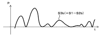
制御装置100のうち、第1加減算器113bは、ハイパスフィルタ111から高周波成分信号S1が入力されると共に、包絡線推定部112bから包絡線信号S2bが入力される。そして、第1加減算器113bは、高周波成分信号S1から包絡線信号S2bを減算する処理を行うことによって、第1加減算器出力信号S3bを算出する。
In the
制御装置100のうち、第2加減算器114bは、第1加減算器出力信号S3bが入力されると共に、カレントトランスフォーマ313から太陽熱発電出力信号Sβが入力される。そして、第2加減算器114bは、第1加減算器出力信号S3bから、太陽熱発電出力信号Sβを減算する処理を行うことによって、第2加減算器出力信号S4bを算出する。そして、第2加減算器114bは、その算出した第2加減算器出力信号S4bを第1関数器112及び第2関数器120に出力する。
In the
そして、第1関数器112では、第4実施形態の場合と同様に、図14に示す関数を用いて、第2加減算器出力信号S4bから第1制御信号S10を算出する処理を行う。そして、第1関数器112は、図19に示すように、その第1制御信号S10をインバータ40に出力する。
Then, in the
この一方で、第2関数器120では、第4実施形態の場合と同様に、図15に示す関数を用いて、第2加減算器出力信号S4bから第2制御信号S20を算出する処理を行う。そして、第2関数器120は、図19に示すように、その第2制御信号S20を出力制御装置50に出力する。
On the other hand, as in the case of the fourth embodiment, the
[B]動作
図20A,図20B,図20C,図20D,図21A,図21Bは、第5実施形態に係る発電システムにおいて、制御装置で用いられるデータを示す図である。[B] Operation FIGS. 20A, 20B, 20C, 20D, 21A, and 21B are diagrams showing data used in the control device in the power generation system according to the fifth embodiment.
図20Aは、包絡線信号S2bを示し、図20Bは、第1加減算器出力信号S3bを示し、図20Cは、太陽熱発電出力信号Sβを示し、図20Dは、第2加減算器出力信号S4bを示している。また、図21Aは、第1制御信号S10を示し、図21Bは、第2制御信号S20を示している。各図では、横軸が時間tであり、縦軸がデータ値Pである。 20A shows the envelope signal S2b, FIG. 20B shows the first adder / subtracter output signal S3b, FIG. 20C shows the solar thermal power generation output signal Sβ, and FIG. 20D shows the second adder / subtractor output signal S4b. ing. FIG. 21A shows the first control signal S10, and FIG. 21B shows the second control signal S20. In each figure, the horizontal axis is time t, and the vertical axis is the data value P.
以下より、図19に示した制御装置100の動作について、図20A,図20B,図20C,図20D,図21A,図21Bを参照して詳細に説明する。
Hereinafter, the operation of the
まず、図19に示すように、制御装置100では、第4実施形態の場合と同様に、ハイパスフィルタ111に風力発電出力信号Sα(図16A参照)が入力される。そして、その入力された風力発電出力信号Sαについてハイパスフィルタ111がハイパスフィルタリング処理を行うことによって高周波成分信号S1(図16C参照)を算出し、その後、包絡線推定部112bへ出力する。
First, as shown in FIG. 19, in the
つぎに、図19に示すように、ハイパスフィルタ111が出力した高周波成分信号S1から包絡線推定部112bが包絡線信号S2bを算出する。図20Aに示すように、包絡線信号S2bは、高周波成分信号S1(図16C参照)の包絡線のうち、極小値側の包絡線のデータに相当する。
Next, as shown in FIG. 19, the
つぎに、図19に示すように、包絡線信号S2b及び高周波成分信号S1から、第1加減算器113bが第1加減算器出力信号S3bを算出する。図20Bに示すように、第1加減算器出力信号S3bは、高周波成分信号S1から包絡線信号S2bを減算したデータに相当する(S3b=S1−S2b)。 Next, as shown in FIG. 19, the first adder / subtractor 113b calculates the first adder / subtracter output signal S3b from the envelope signal S2b and the high frequency component signal S1. As shown in FIG. 20B, the first adder / subtracter output signal S3b corresponds to data obtained by subtracting the envelope signal S2b from the high-frequency component signal S1 (S3b = S1-S2b).
つぎに、図19に示すように、第1加減算器出力信号S3b及び太陽熱発電出力信号Sβから第2加減算器114bが第2加減算器出力信号S4bを算出する。図20C,図20Dに示すように、第2加減算器出力信号S4bは、第1加減算器出力信号S3bから太陽熱発電出力信号Sβを減算したデータに相当する。
Next, as shown in FIG. 19, the second adder /
つぎに、図19に示すように、第2加減算器出力信号S4bから第1関数器112が第1制御信号S10を算出する。図21Aに示すように、第1制御信号S10は、第2加減算器出力信号S4b(図20D参照)のうち、正成分について抽出されたデータに相当する。
Next, as shown in FIG. 19, the
これと共に、図19に示すように、第2加減算器出力信号S4bから第2関数器120が第2制御信号S20を算出する。図21Bに示すように、第2制御信号S20は、第2加減算器出力信号S4b(図20D参照)のうち、負成分について抽出した後に、その抽出したデータについて符号を反転させたデータに相当する。換言すると、第2制御信号S20は、第2加減算器出力信号S4b(図20D参照)から、第1制御信号S10(図21A参照)を減算することによって第2加減算器出力信号S4bの負成分について抽出した後に、その第2加減算器出力信号S4bの負成分について正負を反転させた信号である。
At the same time, as shown in FIG. 19, the
その後、図19に示すように、上記のように算出された第1制御信号S10は、インバータ40に出力される。このときは、図12に示すように、インバータ40では、第4実施形態の場合と同様に、第1制御信号S10に応じて、風力発電装置2が出力する電力E1のうち一部の電力E12を第1送電線200からヒータ133に出力する。そして、その出力した電力E12によってヒータ133が、第1配管131の内部を流れる熱媒F1を加熱する。
Thereafter, as shown in FIG. 19, the first control signal S10 calculated as described above is output to the
また、図19に示すように、上記のように算出された第2制御信号S20は、出力制御装置50に出力される。このとき、図12に示すように、出力制御装置50では、第4実施形態の場合と同様に、第2制御信号S20に応じて、太陽熱発電装置3が出力する電力E2を調整し、第2送電線300を介して、第1送電線200に出力する。電力E2は、風力発電装置2が出力する電力E1から、ヒータ133へ出力された一部の電力E12が差分された電力E11に合成されて、電力系統に出力される。
As shown in FIG. 19, the second control signal S20 calculated as described above is output to the
このため、本実施形態では、第4実施形態の場合と同様に、風力発電装置2から電力系統へ最終的に出力される電力E3は、平滑化され、揺らぎが低減された状態になる。
For this reason, in this embodiment, as in the case of the fourth embodiment, the electric power E3 that is finally output from the
[C]まとめ
以上のように、本実施形態では、制御装置100は、電力E1に応じて得られた風力発電出力信号Sαの他に、電力E2に応じて得られた太陽熱発電出力信号Sβに基づいて、第1制御信号S10をインバータ40に出力すると共に、第2制御信号S20を出力制御装置50に出力する。具体的には、制御装置100では、包絡線推定部112bが、高周波成分信号S1の包絡線のうち極小値側の包絡線について推定する処理を行うことによって、包絡線信号S2bを算出する。そして、第1加減算器113bが高周波成分信号S1から包絡線信号S2bを減算する処理を行うことによって、第1加減算器出力信号S3bを算出する。そして、第2加減算器114bが第1加減算器出力信号S3bから太陽熱発電出力信号Sβを減算する処理を行うことによって第2加減算器出力信号S4bを算出する。その後、第1関数器112(第1制御信号算出部)が、第2加減算器出力信号S4bのうち正成分を抽出することによって第1制御信号S10を算出する。これと共に、第2関数器120(第2制御信号算出部)が、第2加減算器出力信号S4bのうち負成分を抽出することによって第2制御信号S20を算出する。[C] Summary As described above, in the present embodiment, the
このため、本実施形態では、第4実施形態の場合と同様に、風力発電装置2から第1送電線200を介して電力系統へ最終的に出力される電力E3を平滑化することができる。
For this reason, in this embodiment, similarly to the case of the fourth embodiment, it is possible to smooth the electric power E3 that is finally output from the
したがって、本実施形態は、発電出力の平滑化が容易であって、電力の安定化を容易に実現することができる。 Therefore, according to the present embodiment, the power generation output can be easily smoothed and the power can be easily stabilized.
また、本実施形態においては、包絡線推定部112bは、高周波成分信号S1において、直前に検出した第1極小値と、その第1極小値の直前に検出した第2極小値とを直線で結び、外挿することによって、包絡線信号S2bを算出する。この場合、ヒータ133によって熱に変換される、風力発電の電力が減少する。熱に変換すると太陽熱発電の発電効率をかけた部分しか電力に戻らないので、一般的には20から30%程度の効率となる。したがって、70〜80%程度は、損失となる。したがって、ヒータ133によって熱に変換される電力が減少すると、全体としての損失が減少し、大変好ましい。
In the present embodiment, the
以上、本発明のいくつかの実施形態を説明したが、これらの実施形態は、例として提示したものであり、発明の範囲を限定することは意図していない。これら新規な実施形態は、その他の様々な形態で実施することが可能であり、発明の要旨を逸脱しない範囲で、種々の省略、置き換え、変更を行うことができる。これらの実施形態やその変形例は、発明の範囲や要旨に含まれると共に、特許請求の範囲に記載された発明とその均等の範囲に含まれる。 As mentioned above, although some embodiment of this invention was described, these embodiment is shown as an example and is not intending limiting the range of invention. These novel embodiments can be implemented in various other forms, and various omissions, replacements, and changes can be made without departing from the spirit of the invention. These embodiments and modifications thereof are included in the scope and gist of the invention, and are included in the invention described in the claims and the equivalents thereof.
また上記実施形態に示した各構成要素を、コンピュータのハードディスク装置などのストレージにインストールしたプログラムで実現してもよく、また上記プログラムを、コンピュータ読取可能な電子媒体(electronic media)に記憶しておき、プログラムを電子媒体からコンピュータに読み取らせることで本発明の機能をコンピュータが実現するようにしてもよい。電子媒体としては、例えばCD−ROM等の記録媒体やフラッシュメモリ、リムーバブルメディア(Removable media)等が含まれる。さらに、ネットワークを介して接続した異なるコンピュータに構成要素を分散して記憶し、各構成要素を機能させたコンピュータ間で通信することで実現してもよい。 Each component shown in the above embodiment may be realized by a program installed in a storage such as a hard disk device of a computer, and the above program is stored in a computer-readable electronic medium. The computer may realize the functions of the present invention by causing the computer to read the program from the electronic medium. Examples of the electronic medium include a recording medium such as a CD-ROM, a flash memory, and a removable media. Further, the configuration may be realized by distributing and storing components in different computers connected via a network, and communicating between computers in which the components are functioning.
1…発電システム、2…風力発電装置、2a…翼(羽根)、2b…ナセル、2c…タワー(塔)、3…太陽熱発電装置、5…ヒータ、6…ミラー、8…パイプ、9…熱媒移送ポンプ、10…熱媒循環流路、12…作動流体循環流路、14…熱交換器、15…タービン、16…発電機、20…作動流体移送ポンプ、21…発電機、22…パワーコンディショナ、23…計器用変流器(カレントトランスフォーマ)、24…インバータ電源回路、25…変圧器、26…ハイパスフィルタ、27…平滑化フィルタ、28…減算器、29…加算器、30…電熱変換部、31…電力変換制御部、32…関数器、33…電力変換部、40…インバータ、50…出力制御装置、51…温度センサ、52…熱媒加熱制御部、52a…熱媒耐熱温度記憶部、52b…熱媒加熱状況予測部、53…ミラー駆動部、100…制御装置、131…第1配管、132…曲面ミラー、133…ヒータ、134…熱交換器、135…第1ポンプ、111…ハイパスフィルタ、111a…ローパスフィルタ、111b…加減算器、112…第1関数器、112b…包絡線推定部、113b…第1加減算器、114b…第2加減算器、120…第2関数器、200…第1送電線、211…ハブ、212…ブレード、213…シャフト、300…第2送電線、301…第2配管、302…タービン、303…発電機、304…凝縮器、305…冷却塔、306…第2ポンプ、307…第3ポンプ、308…主蒸気弁、313…カレントトランスフォーマ、321…変圧器、600…発電制御装置、621…風のゆらぎフォロワー、622…タワーシャドウ効果オブザーバ、623…オブザーバ部、624…タワーシャドウ効果電力計算部、625…メモリ、626…短期変動電力抽出部、627…包絡線生成部、628…短期変動成分分離部、629…制御部、630…インバータ(INV)、S1…高周波成分信号、S10…第1制御信号、S1a…低周波成分信号、S20…第2制御信号、S2b…包絡線信号、S3b…第1加減算器出力信号、S4b…第2加減算器出力信号、Sα…風力発電出力信号、Sβ…太陽熱発電出力信号。
DESCRIPTION OF
Claims (14)
太陽熱により熱媒を加熱する加熱器と、前記加熱器により加熱された前記熱媒の熱と発電機の駆動機構を作動させる作動流体の熱とを熱交換する熱交換器と、を有する太陽熱発電装置と、
前記風力発電装置により発電された電力を、前記熱媒を加熱する熱に変換する電熱変換部と、
を備え、前記風力発電装置により発電された電力のうちの所定の周波数よりも高い高周波成分を前記電熱変換部へ与えて前記熱媒を加熱する熱に変換し、残部を配電系統へ出力する発電システム。 A wind power generator,
Solar power generation comprising: a heater that heats a heat medium by solar heat; and a heat exchanger that exchanges heat between heat of the heat medium heated by the heater and heat of a working fluid that operates a drive mechanism of the generator. Equipment,
An electrothermal converter that converts the electric power generated by the wind power generator into heat for heating the heat medium;
Generating high-frequency components higher than a predetermined frequency in the electric power generated by the wind power generator , converting the heat into heat to heat the heating medium, and outputting the remainder to the distribution system system.
電気ヒータと、
供給される電力を前記電気ヒータの駆動電力に変換するための電力変換部と、
前記風力発電装置による発電電力の前記高周波成分が前記電気ヒータの駆動電力に変換されるように前記電力変換部の動作を制御するハイパスフィルタを含む電力変換制御部と、
を備える請求項1記載の発電システム。 The electrothermal converter is
An electric heater;
A power converter for converting supplied power into driving power of the electric heater;
A power conversion control unit including a high-pass filter that controls the operation of the power conversion unit so that the high-frequency component of the power generated by the wind power generator is converted into the driving power of the electric heater;
A power generation system according to claim 1 .
太陽光を集光するミラーと、
前記熱媒が内部を移送されるパイプと、
前記パイプに対する前記ミラーの相対的な向きを変更するミラー駆動部と、
を有し、
前記パイプを流路の一部として備え、前記加熱器、前記電熱変換部及び前記熱交換器を経由しながら前記熱媒が循環される熱媒循環流路と、
前記熱媒循環流路を循環する前記熱媒の温度を検出する温度センサと、
前記温度センサによる検出結果に基づいて、前記ミラー駆動部の動作を制御する熱媒加熱制御部と、
をさらに備える請求項1ないし3のいずれか1項に記載の発電システム。 The heater is
A mirror that collects sunlight,
A pipe through which the heat medium is transferred;
A mirror drive for changing the relative orientation of the mirror with respect to the pipe;
Have
The pipe as a part of the flow path, a heat medium circulation flow path through which the heat medium is circulated while passing through the heater, the electrothermal conversion unit, and the heat exchanger;
A temperature sensor for detecting the temperature of the heat medium circulating in the heat medium circulation channel;
Based on the detection result by the temperature sensor, a heating medium heating control unit that controls the operation of the mirror driving unit,
Power generation system according to any one of claims 1 to 3 further comprising a.
前記熱媒加熱制御部は、前記温度センサによる検出結果に基づいて、前記熱媒移送ポンプの動作を制御する、
請求項4記載の発電システム。 A heat medium transfer pump for generating power for transferring the heat medium along the heat medium circulation flow path;
The heating medium heating control unit controls the operation of the heating medium transfer pump based on a detection result by the temperature sensor.
The power generation system according to claim 4 .
前記風力発電により得られる風力発電電力から平滑化された平滑電力信号を生成する平滑電力信号生成部と、
前記平滑電力信号生成部により生成された平滑電力信号と、前記風車から測定した前記風車の回転数と、予め記憶された前記風車の羽根の回転を模擬するデータとを基に、回転する前記風車の羽根が前記風車の塔を通過する際の発電出力の減少量を求め、前記減少量を前記平滑電力信号から差し引くことでタワーシャドウ効果電力を生成するタワーシャドウ効果電力生成部と、
前記タワーシャドウ効果電力生成部により生成されたタワーシャドウ効果電力と、前記平滑電力信号生成部から出力された平滑電力信号とを基に、短期で上下に変動する前記風力発電電力の下限値を結ぶ包絡線を生成する包絡線生成部と、
前記包絡線生成部により生成された包絡線に従い前記風力発電電力から短期の変動成分を分離する短期変動成分分離部と、
前記短期変動成分分離部により分離された短期の変動成分を、前記熱媒循環用のパイプを加熱するヒータを駆動する電力に変換する電力変換部と
を備える発電システム。 Wind power generation that generates power by rotating a windmill, and solar power generation that uses the heat medium for power generation by heating the heat medium circulating in the heat medium circulation pipe with the heat collected by the solar heat collector In the combined power generation system,
A smooth power signal generator that generates a smooth power signal smoothed from wind power generated by the wind power;
The wind turbine that rotates based on the smooth power signal generated by the smooth power signal generation unit, the rotational speed of the wind turbine measured from the wind turbine, and data that simulates the rotation of the blades of the wind turbine stored in advance. A tower shadow effect power generation unit that generates a tower shadow effect power by subtracting the decrease amount from the smooth power signal, and obtaining a decrease amount of the power generation output when the blades of the windmill pass through the tower of the windmill,
Based on the tower shadow effect power generated by the tower shadow effect power generation unit and the smooth power signal output from the smooth power signal generation unit, a lower limit value of the wind power generation power that fluctuates up and down in a short time is connected. An envelope generator for generating an envelope;
A short-term fluctuation component separating unit that separates short-term fluctuation components from the wind power according to the envelope generated by the envelope generation unit;
A power generation system comprising: a power conversion unit that converts the short-term fluctuation component separated by the short-term fluctuation component separation unit into electric power that drives a heater that heats the pipe for circulating the heat medium.
前記タワーシャドウ効果電力を前記風力発電電力に加えて得た電力信号から、前記シャドウ効果電力の振幅を差し引いて包絡線を生成する請求項6記載の発電システム。 The envelope generator is
The power generation system according to claim 6 , wherein an envelope is generated by subtracting an amplitude of the shadow effect power from a power signal obtained by adding the tower shadow effect power to the wind power generation power.
前記風車の羽根が前記塔の陰になるタイミングを計算し、前記タイミングでのトルク減少を計算し、前記トルク減少による発電量の減少量を計算するタワーシャドウ効果電力計算部を備える請求項6記載の発電システム。 The tower shadow effect power generator is
The timing at which the blades of the wind turbine is in the shadow of the tower to calculate the torque reduction at the timing calculated, according to claim 6 comprising a tower shadow effect power calculation unit that calculates a reduction amount of the power generation amount by the torque reduction Power generation system.
前記風力発電電力を、1秒〜60秒の時定数で遅らせて平滑し出力する遅れフィルタを備える請求項6記載の発電システム。 The smooth power generator
The power generation system according to claim 6, further comprising a delay filter that delays and smoothes the wind power generated by a time constant of 1 second to 60 seconds.
太陽熱及びヒータで加熱された熱媒と熱交換がされた作動流体により発電した第2電力を第2送電線に出力する太陽熱発電装置と、
前記第1電力のうち一部の電力を第1制御信号に応じて前記ヒータに出力するインバータと、
前記第2電力を第2制御信号に応じて出力調整し、前記第1送電線に出力する出力制御装置と、
前記第1電力について得られた風力発電出力信号に基づいて、前記第1制御信号を前記インバータに出力すると共に、前記第2制御信号を前記出力制御装置に出力する制御装置とを備え、
前記制御装置は、
前記風力発電出力信号に含まれる高周波成分信号を抽出するハイパスフィルタと、
前記高周波成分信号のうち正成分を抽出して得られる信号を前記第1制御信号として算出する第1制御信号算出部と、
前記高周波成分信号のうち負成分を抽出する共に正負を反転して得られる信号を、前記第2制御信号として算出する第2制御信号算出部とを有することを特徴とする、
発電システム。 A wind turbine generator that outputs the first power generated by wind power to the first transmission line;
A solar power generator that outputs, to the second power transmission line, the second electric power generated by the working fluid that has been subjected to heat exchange with the heat medium heated by the solar heat and the heater;
An inverter that outputs a part of the first power to the heater in response to a first control signal;
An output control device that adjusts the output of the second power in accordance with a second control signal and outputs the second power to the first power transmission line;
A control device that outputs the first control signal to the inverter and outputs the second control signal to the output control device based on a wind power generation output signal obtained for the first power;
The controller is
A high-pass filter that extracts a high-frequency component signal contained in the wind power generation output signal;
A first control signal calculator that calculates a signal obtained by extracting a positive component from the high-frequency component signal as the first control signal;
A second control signal calculating unit that calculates a signal obtained by extracting a negative component from the high-frequency component signal and inverting the positive and negative as the second control signal,
Power generation system.
請求項10に記載の発電システム。 The high-pass filter has a time constant smaller than 1 minute,
The power generation system according to claim 10 .
請求項10または11に記載の発電システム。 The control device outputs a signal obtained by adding a bias to a signal obtained by extracting a negative component from the high-frequency component signal in the second control signal calculation unit as the second control signal to the output control device. It is characterized by
The power generation system according to claim 10 or 11 .
太陽熱及びヒータで加熱された熱媒と熱交換がされた作動流体によって発電した第2電力を第2送電線に出力する太陽熱発電装置と、
前記第1電力のうち一部の電力を、第1制御信号に応じて前記ヒータに出力するインバータと、
前記第2電力を第2制御信号に応じて出力調整し、前記第1送電線に出力する出力制御装置と、
前記第1電力について得られた風力発電出力信号、及び、前記第2電力について得られた太陽熱発電出力信号に基づいて、前記第1制御信号を前記インバータに出力すると共に、前記第2制御信号を前記出力制御装置に出力する制御装置とを備え、
前記制御装置は、
前記風力発電出力信号に含まれる高周波成分信号を抽出するハイパスフィルタと、
前記高周波成分信号の包絡線のうち極小値側の包絡線について推定する処理を行うことによって包絡線信号を算出する包絡線推定部と、
前記高周波成分信号から前記包絡線信号を減算する処理を行うことによって、第1加減算器出力信号を算出する第1加減算器と、
前記第1加減算器出力信号から前記太陽熱発電出力信号を減算する処理を行うことによって第2加減算器出力信号を算出する第2加減算器と、
前記第2加減算器出力信号のうち正成分を抽出して得られる信号を前記第1制御信号として算出する第1制御信号算出部と、
前記第2加減算器出力信号のうち負成分を抽出する共に正負を反転して得られる信号を、前記第2制御信号として算出する第2制御信号算出部とを有することを特徴とする、
発電システム。 A wind power generator that outputs first power generated by wind power to the first transmission line;
A solar power generator that outputs, to the second power transmission line, the second power generated by the working fluid that has been subjected to heat exchange with the heat medium heated by the solar heat and the heater;
An inverter that outputs a part of the first power to the heater in response to a first control signal;
An output control device that adjusts the output of the second power in accordance with a second control signal and outputs the second power to the first power transmission line;
Based on the wind power generation output signal obtained for the first power and the solar power generation output signal obtained for the second power, the first control signal is output to the inverter, and the second control signal is A control device for outputting to the output control device,
The controller is
A high-pass filter that extracts a high-frequency component signal contained in the wind power generation output signal;
An envelope estimator that calculates an envelope signal by performing a process of estimating an envelope on the minimum value side of the envelope of the high-frequency component signal;
A first adder / subtractor that calculates a first adder / subtracter output signal by performing a process of subtracting the envelope signal from the high-frequency component signal;
A second adder / subtractor that calculates a second adder / subtracter output signal by performing a process of subtracting the solar thermal power generation output signal from the first adder / subtracter output signal;
A first control signal calculation unit that calculates a signal obtained by extracting a positive component from the second adder / subtracter output signal as the first control signal;
A second control signal calculation unit configured to calculate a signal obtained by extracting a negative component from the second adder / subtracter output signal and inverting the positive / negative as the second control signal,
Power generation system.
請求項13に記載の発電システム。 The envelope estimation unit connects the first minimum value detected immediately before the second minimum value detected immediately before the first minimum value with a straight line in the high-frequency component signal, and extrapolates the envelope. Calculating a line signal,
The power generation system according to claim 13 .
Applications Claiming Priority (7)
| Application Number | Priority Date | Filing Date | Title |
|---|---|---|---|
| JP2012175413 | 2012-08-07 | ||
| JP2012175414 | 2012-08-07 | ||
| JP2012175415 | 2012-08-07 | ||
| JP2012175414 | 2012-08-07 | ||
| JP2012175413 | 2012-08-07 | ||
| JP2012175415 | 2012-08-07 | ||
| PCT/JP2013/004589 WO2014024415A1 (en) | 2012-08-07 | 2013-07-29 | Power generation system |
Publications (2)
| Publication Number | Publication Date |
|---|---|
| JPWO2014024415A1 JPWO2014024415A1 (en) | 2016-07-25 |
| JP6139530B2 true JP6139530B2 (en) | 2017-05-31 |
Family
ID=50067675
Family Applications (1)
| Application Number | Title | Priority Date | Filing Date |
|---|---|---|---|
| JP2014529272A Active JP6139530B2 (en) | 2012-08-07 | 2013-07-29 | Power generation system |
Country Status (4)
| Country | Link |
|---|---|
| US (1) | US9903344B2 (en) |
| JP (1) | JP6139530B2 (en) |
| AU (1) | AU2013301058B2 (en) |
| WO (1) | WO2014024415A1 (en) |
Families Citing this family (7)
| Publication number | Priority date | Publication date | Assignee | Title |
|---|---|---|---|---|
| MA40950A (en) * | 2014-11-12 | 2017-09-19 | 8 Rivers Capital Llc | SUITABLE CONTROL SYSTEMS AND PROCEDURES FOR USE WITH POWER GENERATION SYSTEMS AND PROCESSES |
| JP6407082B2 (en) * | 2015-03-27 | 2018-10-17 | 株式会社東芝 | Hydrogen production system |
| JP6574891B2 (en) * | 2016-02-29 | 2019-09-11 | 株式会社東芝 | Hydrogen production system and hydrogen production method |
| CN108799002A (en) * | 2017-05-01 | 2018-11-13 | 李启飞 | Wind drives the hot energy storage peak shaving formula wind generator system of mangneto |
| WO2019058716A1 (en) | 2017-09-22 | 2019-03-28 | 三菱日立パワーシステムズ株式会社 | Solar thermal power generation equipment |
| JP6659790B2 (en) * | 2018-09-10 | 2020-03-04 | 株式会社東芝 | Hydrogen production unit, power smoothing device and hydrogen production device |
| EP3852214A1 (en) * | 2020-01-14 | 2021-07-21 | Wobben Properties GmbH | Method for controlling a wind energy system |
Family Cites Families (28)
| Publication number | Priority date | Publication date | Assignee | Title |
|---|---|---|---|---|
| US4164123A (en) * | 1976-08-25 | 1979-08-14 | Smith Otto J M | Solar thermal electric power plant |
| US4206608A (en) * | 1978-06-21 | 1980-06-10 | Bell Thomas J | Natural energy conversion, storage and electricity generation system |
| JPH03189372A (en) * | 1989-12-18 | 1991-08-19 | Hitachi Ltd | Pollution-free energy feeding system |
| US5384489A (en) * | 1994-02-07 | 1995-01-24 | Bellac; Alphonse H. | Wind-powered electricity generating system including wind energy storage |
| JPH09189285A (en) * | 1996-01-08 | 1997-07-22 | Ota Gijutsu Jimusho:Kk | Wind power generating device |
| US6372978B1 (en) * | 2000-12-21 | 2002-04-16 | Carmine Cifaldi | Wind/sun solar collection system (HS2) |
| US20020084655A1 (en) * | 2000-12-29 | 2002-07-04 | Abb Research Ltd. | System, method and computer program product for enhancing commercial value of electrical power produced from a renewable energy power production facility |
| JP4092949B2 (en) * | 2002-05-14 | 2008-05-28 | 株式会社日立製作所 | Wind power generator equipped with secondary battery, converter control device, and power converter control method |
| JP2004069197A (en) * | 2002-08-07 | 2004-03-04 | Jmc Geothermal Engineering Co Ltd | System using natural energy/underground heat together, and operating method thereof |
| RU2249125C1 (en) * | 2003-09-24 | 2005-03-27 | Царев Виктор Владимирович | Self-contained power and heat supply system of rooms in dwelling houses and industrial areas |
| US7055519B2 (en) * | 2003-12-10 | 2006-06-06 | United Technologies Corporation | Solar collector and method |
| CA2574830C (en) * | 2004-07-23 | 2014-04-15 | New World Generation Inc. | Electric power plant with thermal storage medium |
| US20080121525A1 (en) * | 2005-10-11 | 2008-05-29 | Doland George J | Renewable Power Controller for Hydrogen Production |
| JP4872393B2 (en) * | 2006-03-14 | 2012-02-08 | 株式会社日立製作所 | Wind power generation hydrogen production system |
| JP5022233B2 (en) * | 2006-06-16 | 2012-09-12 | 川崎重工業株式会社 | Solar thermal power generation equipment, heat medium supply equipment, and temperature fluctuation suppression device |
| JP2008298389A (en) * | 2007-06-01 | 2008-12-11 | Tetsuzo Fukuda | Floor heating system |
| US9966763B2 (en) * | 2007-06-07 | 2018-05-08 | Allen L. Witters | Integrated multiple fuel renewable energy system |
| WO2009035363A1 (en) * | 2007-09-14 | 2009-03-19 | Viktor Vladimirovich Tsarev | Autonomous power supply system |
| JP5557525B2 (en) * | 2009-12-28 | 2014-07-23 | 株式会社日立製作所 | Wind power generation system and control method for wind power generation system |
| JP2011169171A (en) * | 2010-02-16 | 2011-09-01 | Sumitomo Electric Ind Ltd | Power generation system |
| CN102200320A (en) * | 2010-03-25 | 2011-09-28 | 刘军 | Wind power generation heat supply device |
| GB201005801D0 (en) * | 2010-04-07 | 2010-05-26 | Cooper Timothy P | A localy based electricity supply management system and method |
| KR101303404B1 (en) * | 2010-08-26 | 2013-09-05 | 미츠비시 쥬고교 가부시키가이샤 | Wind power generation apparatus and output-controlling method |
| JP5743487B2 (en) * | 2010-10-25 | 2015-07-01 | イビデン株式会社 | Heat collector tube, collector, and concentrating solar power generation system |
| JP2012100487A (en) | 2010-11-04 | 2012-05-24 | Toshiba Mitsubishi-Electric Industrial System Corp | Power system stabilizing apparatus |
| JP2012112298A (en) * | 2010-11-24 | 2012-06-14 | Sumitomo Electric Ind Ltd | Heat generating machine and wind-force thermal power generation system |
| US20120325290A1 (en) * | 2011-06-27 | 2012-12-27 | Integrated Power Technology Corporation | Solar cogeneration vessel |
| JP5868809B2 (en) * | 2012-08-06 | 2016-02-24 | 株式会社東芝 | Power plant and heat supply method |
-
2013
- 2013-07-29 JP JP2014529272A patent/JP6139530B2/en active Active
- 2013-07-29 AU AU2013301058A patent/AU2013301058B2/en active Active
- 2013-07-29 WO PCT/JP2013/004589 patent/WO2014024415A1/en active Application Filing
-
2015
- 2015-02-05 US US14/614,599 patent/US9903344B2/en active Active
Also Published As
| Publication number | Publication date |
|---|---|
| US20150145254A1 (en) | 2015-05-28 |
| AU2013301058A1 (en) | 2015-02-26 |
| AU2013301058B2 (en) | 2017-02-02 |
| US9903344B2 (en) | 2018-02-27 |
| JPWO2014024415A1 (en) | 2016-07-25 |
| WO2014024415A1 (en) | 2014-02-13 |
Similar Documents
| Publication | Publication Date | Title |
|---|---|---|
| JP6139530B2 (en) | Power generation system | |
| CN102474212B (en) | Power generation device and control method therefor | |
| Zhao et al. | ${\cal L} _1 $ adaptive speed control of a small wind energy conversion system for maximum power point tracking | |
| Zhang et al. | Maximum power point tracking algorithms for wind power generation system: Review, comparison and analysis | |
| CN101776043B (en) | Error compensation model-based wind turbine generator maximum wind energy capture control method | |
| CN108475929B (en) | Method for controlling a wind power plant | |
| KR101370542B1 (en) | Method for controling mppt using wind speed estimation of wind power generation system | |
| US20070173982A1 (en) | Systems and methods for controlling a ramp rate of a wind farm | |
| Sabzevari et al. | MPPT control of wind turbines by direct adaptive fuzzy-PI controller and using ANN-PSO wind speed estimator | |
| Li et al. | Control and monitoring for grid-friendly wind turbines: Research overview and suggested approach | |
| EP3749853A1 (en) | Determining control settings for a wind turbine | |
| US20150263521A1 (en) | Line impedance compensation system | |
| CN105932916A (en) | System And Method For Stabilizing Sub-synchronous Interaction Of Wind Turbine Generator | |
| Sarkar et al. | A study of MPPT schemes in PMSG based wind turbine system | |
| JP5908334B2 (en) | Electrolytic hydrogen generation system, electrolytic hydrogen generation method and program | |
| Smida et al. | Different conventional strategies of pitch angle control for variable speed wind turbines | |
| Toumi et al. | Robust variable step P&O algorithm based MPPT for PMSG wind generation system using estimated wind speed compensation technique | |
| CN109356799A (en) | A kind of no air velocity transducer Wind turbines powerinjected method method | |
| Manna et al. | A review of control techniques for wind energy conversion system | |
| De Zutter et al. | Modeling of active yaw systems for small and medium wind turbines | |
| JP2010025028A (en) | Output electric power fluctuation restraining device of wind power generator | |
| Diab et al. | Performance of doubly-fed induction generator based wind turbine using adaptive neuro-fuzzy inference system | |
| JP5549147B2 (en) | Switching power supply device, generator and power supply device | |
| JP5549146B2 (en) | Switching power supply device, generator and power supply device | |
| GB2483315A (en) | Control of water current turbines |
Legal Events
| Date | Code | Title | Description |
|---|---|---|---|
| A131 | Notification of reasons for refusal |
Free format text: JAPANESE INTERMEDIATE CODE: A131 Effective date: 20161018 |
|
| A521 | Request for written amendment filed |
Free format text: JAPANESE INTERMEDIATE CODE: A523 Effective date: 20161219 |
|
| A131 | Notification of reasons for refusal |
Free format text: JAPANESE INTERMEDIATE CODE: A131 Effective date: 20170124 |
|
| A521 | Request for written amendment filed |
Free format text: JAPANESE INTERMEDIATE CODE: A523 Effective date: 20170323 |
|
| TRDD | Decision of grant or rejection written | ||
| A01 | Written decision to grant a patent or to grant a registration (utility model) |
Free format text: JAPANESE INTERMEDIATE CODE: A01 Effective date: 20170404 |
|
| A61 | First payment of annual fees (during grant procedure) |
Free format text: JAPANESE INTERMEDIATE CODE: A61 Effective date: 20170427 |
|
| R151 | Written notification of patent or utility model registration |
Ref document number: 6139530 Country of ref document: JP Free format text: JAPANESE INTERMEDIATE CODE: R151 |


