JP6139518B2 - Positioning for ECG mapping - Google Patents
Positioning for ECG mapping Download PDFInfo
- Publication number
- JP6139518B2 JP6139518B2 JP2014519299A JP2014519299A JP6139518B2 JP 6139518 B2 JP6139518 B2 JP 6139518B2 JP 2014519299 A JP2014519299 A JP 2014519299A JP 2014519299 A JP2014519299 A JP 2014519299A JP 6139518 B2 JP6139518 B2 JP 6139518B2
- Authority
- JP
- Japan
- Prior art keywords
- heart
- patient
- signal
- electrical signal
- positioning
- Prior art date
- Legal status (The legal status is an assumption and is not a legal conclusion. Google has not performed a legal analysis and makes no representation as to the accuracy of the status listed.)
- Expired - Fee Related
Links
Images


Classifications
-
- A—HUMAN NECESSITIES
- A61—MEDICAL OR VETERINARY SCIENCE; HYGIENE
- A61B—DIAGNOSIS; SURGERY; IDENTIFICATION
- A61B5/00—Measuring for diagnostic purposes; Identification of persons
- A61B5/24—Detecting, measuring or recording bioelectric or biomagnetic signals of the body or parts thereof
- A61B5/25—Bioelectric electrodes therefor
- A61B5/279—Bioelectric electrodes therefor specially adapted for particular uses
- A61B5/28—Bioelectric electrodes therefor specially adapted for particular uses for electrocardiography [ECG]
- A61B5/283—Invasive
-
- A—HUMAN NECESSITIES
- A61—MEDICAL OR VETERINARY SCIENCE; HYGIENE
- A61B—DIAGNOSIS; SURGERY; IDENTIFICATION
- A61B18/00—Surgical instruments, devices or methods for transferring non-mechanical forms of energy to or from the body
- A61B18/04—Surgical instruments, devices or methods for transferring non-mechanical forms of energy to or from the body by heating
- A61B18/12—Surgical instruments, devices or methods for transferring non-mechanical forms of energy to or from the body by heating by passing a current through the tissue to be heated, e.g. high-frequency current
- A61B18/14—Probes or electrodes therefor
- A61B18/1492—Probes or electrodes therefor having a flexible, catheter-like structure, e.g. for heart ablation
-
- A—HUMAN NECESSITIES
- A61—MEDICAL OR VETERINARY SCIENCE; HYGIENE
- A61B—DIAGNOSIS; SURGERY; IDENTIFICATION
- A61B34/00—Computer-aided surgery; Manipulators or robots specially adapted for use in surgery
- A61B34/20—Surgical navigation systems; Devices for tracking or guiding surgical instruments, e.g. for frameless stereotaxis
-
- A—HUMAN NECESSITIES
- A61—MEDICAL OR VETERINARY SCIENCE; HYGIENE
- A61B—DIAGNOSIS; SURGERY; IDENTIFICATION
- A61B5/00—Measuring for diagnostic purposes; Identification of persons
- A61B5/0033—Features or image-related aspects of imaging apparatus, e.g. for MRI, optical tomography or impedance tomography apparatus; Arrangements of imaging apparatus in a room
- A61B5/0036—Features or image-related aspects of imaging apparatus, e.g. for MRI, optical tomography or impedance tomography apparatus; Arrangements of imaging apparatus in a room including treatment, e.g., using an implantable medical device, ablating, ventilating
-
- A—HUMAN NECESSITIES
- A61—MEDICAL OR VETERINARY SCIENCE; HYGIENE
- A61B—DIAGNOSIS; SURGERY; IDENTIFICATION
- A61B5/00—Measuring for diagnostic purposes; Identification of persons
- A61B5/06—Devices, other than using radiation, for detecting or locating foreign bodies ; Determining position of diagnostic devices within or on the body of the patient
- A61B5/061—Determining position of a probe within the body employing means separate from the probe, e.g. sensing internal probe position employing impedance electrodes on the surface of the body
- A61B5/063—Determining position of a probe within the body employing means separate from the probe, e.g. sensing internal probe position employing impedance electrodes on the surface of the body using impedance measurements
-
- A—HUMAN NECESSITIES
- A61—MEDICAL OR VETERINARY SCIENCE; HYGIENE
- A61B—DIAGNOSIS; SURGERY; IDENTIFICATION
- A61B5/00—Measuring for diagnostic purposes; Identification of persons
- A61B5/06—Devices, other than using radiation, for detecting or locating foreign bodies ; Determining position of diagnostic devices within or on the body of the patient
- A61B5/065—Determining position of the probe employing exclusively positioning means located on or in the probe, e.g. using position sensors arranged on the probe
- A61B5/066—Superposing sensor position on an image of the patient, e.g. obtained by ultrasound or x-ray imaging
-
- A—HUMAN NECESSITIES
- A61—MEDICAL OR VETERINARY SCIENCE; HYGIENE
- A61B—DIAGNOSIS; SURGERY; IDENTIFICATION
- A61B5/00—Measuring for diagnostic purposes; Identification of persons
- A61B5/24—Detecting, measuring or recording bioelectric or biomagnetic signals of the body or parts thereof
- A61B5/316—Modalities, i.e. specific diagnostic methods
- A61B5/318—Heart-related electrical modalities, e.g. electrocardiography [ECG]
- A61B5/33—Heart-related electrical modalities, e.g. electrocardiography [ECG] specially adapted for cooperation with other devices
-
- A—HUMAN NECESSITIES
- A61—MEDICAL OR VETERINARY SCIENCE; HYGIENE
- A61B—DIAGNOSIS; SURGERY; IDENTIFICATION
- A61B34/00—Computer-aided surgery; Manipulators or robots specially adapted for use in surgery
- A61B34/20—Surgical navigation systems; Devices for tracking or guiding surgical instruments, e.g. for frameless stereotaxis
- A61B2034/2046—Tracking techniques
- A61B2034/2051—Electromagnetic tracking systems
- A61B2034/2053—Tracking an applied voltage gradient
-
- A—HUMAN NECESSITIES
- A61—MEDICAL OR VETERINARY SCIENCE; HYGIENE
- A61B—DIAGNOSIS; SURGERY; IDENTIFICATION
- A61B5/00—Measuring for diagnostic purposes; Identification of persons
- A61B5/24—Detecting, measuring or recording bioelectric or biomagnetic signals of the body or parts thereof
- A61B5/316—Modalities, i.e. specific diagnostic methods
- A61B5/318—Heart-related electrical modalities, e.g. electrocardiography [ECG]
-
- A—HUMAN NECESSITIES
- A61—MEDICAL OR VETERINARY SCIENCE; HYGIENE
- A61B—DIAGNOSIS; SURGERY; IDENTIFICATION
- A61B5/00—Measuring for diagnostic purposes; Identification of persons
- A61B5/48—Other medical applications
- A61B5/4836—Diagnosis combined with treatment in closed-loop systems or methods
-
- A—HUMAN NECESSITIES
- A61—MEDICAL OR VETERINARY SCIENCE; HYGIENE
- A61N—ELECTROTHERAPY; MAGNETOTHERAPY; RADIATION THERAPY; ULTRASOUND THERAPY
- A61N1/00—Electrotherapy; Circuits therefor
- A61N1/18—Applying electric currents by contact electrodes
- A61N1/32—Applying electric currents by contact electrodes alternating or intermittent currents
- A61N1/36—Applying electric currents by contact electrodes alternating or intermittent currents for stimulation
- A61N1/362—Heart stimulators
- A61N1/3625—External stimulators
-
- A—HUMAN NECESSITIES
- A61—MEDICAL OR VETERINARY SCIENCE; HYGIENE
- A61N—ELECTROTHERAPY; MAGNETOTHERAPY; RADIATION THERAPY; ULTRASOUND THERAPY
- A61N1/00—Electrotherapy; Circuits therefor
- A61N1/18—Applying electric currents by contact electrodes
- A61N1/32—Applying electric currents by contact electrodes alternating or intermittent currents
- A61N1/36—Applying electric currents by contact electrodes alternating or intermittent currents for stimulation
- A61N1/362—Heart stimulators
- A61N1/3628—Heart stimulators using sub-threshold or non-excitatory signals
-
- A—HUMAN NECESSITIES
- A61—MEDICAL OR VETERINARY SCIENCE; HYGIENE
- A61N—ELECTROTHERAPY; MAGNETOTHERAPY; RADIATION THERAPY; ULTRASOUND THERAPY
- A61N1/00—Electrotherapy; Circuits therefor
- A61N1/18—Applying electric currents by contact electrodes
- A61N1/32—Applying electric currents by contact electrodes alternating or intermittent currents
- A61N1/36—Applying electric currents by contact electrodes alternating or intermittent currents for stimulation
- A61N1/362—Heart stimulators
- A61N1/3629—Heart stimulators in combination with non-electric therapy
Landscapes
- Health & Medical Sciences (AREA)
- Life Sciences & Earth Sciences (AREA)
- Engineering & Computer Science (AREA)
- Surgery (AREA)
- Heart & Thoracic Surgery (AREA)
- General Health & Medical Sciences (AREA)
- Public Health (AREA)
- Biomedical Technology (AREA)
- Animal Behavior & Ethology (AREA)
- Veterinary Medicine (AREA)
- Medical Informatics (AREA)
- Molecular Biology (AREA)
- Physics & Mathematics (AREA)
- Pathology (AREA)
- Biophysics (AREA)
- Nuclear Medicine, Radiotherapy & Molecular Imaging (AREA)
- Cardiology (AREA)
- Radiology & Medical Imaging (AREA)
- Human Computer Interaction (AREA)
- Gynecology & Obstetrics (AREA)
- Robotics (AREA)
- Plasma & Fusion (AREA)
- Otolaryngology (AREA)
- Electrotherapy Devices (AREA)
- Measurement And Recording Of Electrical Phenomena And Electrical Characteristics Of The Living Body (AREA)
Description
本開示は、たとえば心電図マッピング用に、物体の位置決めを行うためのシステムおよび方法に関する。 The present disclosure relates to systems and methods for positioning an object, for example, for electrocardiogram mapping.
物体を患者の身体に挿入する低侵襲での手法の一部として、物体が直接的な視線から外れて見えなくなる、さまざまな手法が存在する。このような手法の一例に、静脈または動脈を介して、人間または動物の身体の離れた部分に達するのにカテーテルを用いる電気生理学的研究がある。たとえば、カテーテルの先端に、1つまたは2つ以上の電極などの構成要素が設けられる場合がある。この1つまたは2つ以上の電極などの構成要素は、たとえば、診断(たとえば検知など)機能および/または他の機能(たとえば、刺激またはアブレーションなど)を実施するよう構成できる。このような動作では、カテーテルまたは他の物体の位置を決めると望ましく、これを、位置決めと呼ぶ。 As part of a minimally invasive method of inserting an object into a patient's body, there are a variety of methods in which the object disappears from the direct line of sight. An example of such an approach is an electrophysiological study that uses a catheter to reach a remote part of the human or animal body via a vein or artery. For example, components such as one or more electrodes may be provided at the tip of the catheter. The component, such as the one or more electrodes, can be configured to perform, for example, diagnostic (eg, sensing) functions and / or other functions (eg, stimulation or ablation). In such operations, it is desirable to position the catheter or other object, which is referred to as positioning.
本開示は、物体の位置決めを行うためのシステムおよび方法に関する。 The present disclosure relates to a system and method for positioning an object.
いくつかの例では、患者の体内で物体の位置決めを行うためのシステムを提供可能である。このシステムは、患者の体内で、物体に固定された少なくとも1つの電極に位置決め信号を供給するよう構成されたパルス発生器を含んでもよい。センサーアレイが、位置決め信号に応答して発生した電界を検出し、かつ、それぞれのセンサー信号を供給するよう構成されてもよい。マップ作成部が、それぞれのセンサー信号と、患者の解剖学的形態とセンサーアレイとの幾何学的関係を表す幾何学形状データとに基づいて、電気信号を再構成するよう構成されてもよい。位置計算部が、再構成された電気信号に基づいて、位置決め信号が印加された位置を決定できる。 In some examples, a system for positioning an object within a patient's body can be provided. The system may include a pulse generator configured to provide a positioning signal to at least one electrode secured to the object within the patient's body. The sensor array may be configured to detect an electric field generated in response to the positioning signal and supply a respective sensor signal. The map generator may be configured to reconstruct the electrical signal based on each sensor signal and geometric data representing a geometric relationship between the patient anatomy and the sensor array. The position calculation unit can determine the position to which the positioning signal is applied based on the reconstructed electrical signal.
他の例では、物体の位置決めを行うための方法を行うことが可能である。この方法は、物体に結合した電極に供給される位置決め信号を制御して、患者の組織に電界を発生させることを含んでもよい。また、この方法は、電界に対応する電気信号の検知に基づいて、検知された電気データをメモリーに格納することと、幾何学形状データをメモリーに格納することと、を含んでもよい。幾何学形状データは、患者の解剖学的形態と、電界の検出に用いられる複数のセンサーとの幾何学的関係を表すものであってもよい。また、この方法は、幾何学形状データおよび検知された電気信号に基づいて、組織に対する解剖学的な膜で、電気信号を再構成することを含んでもよい。再構成された電気信号を分析して、位置決め信号が印加された位置を決定できる。この方法は、コンピューターに実装される方法として実現されてもよいし、たとえばプロセッサーによって実行されてもよいなど、読み取り可能な媒体に格納された、実行可能な命令として実現されてもよい。 In another example, a method for positioning an object can be performed. The method may include controlling a positioning signal supplied to an electrode coupled to the object to generate an electric field in the patient's tissue. The method may also include storing detected electrical data in a memory and storing geometric shape data in the memory based on detection of an electrical signal corresponding to the electric field. The geometric shape data may represent a geometric relationship between a patient's anatomy and a plurality of sensors used to detect an electric field. The method may also include reconstructing the electrical signal with an anatomical membrane for the tissue based on the geometric shape data and the sensed electrical signal. The reconstructed electrical signal can be analyzed to determine the position where the positioning signal was applied. This method may be implemented as a computer-implemented method or may be implemented as executable instructions stored on a readable medium, such as may be executed by a processor.
関連出願へのクロスリファレンス
本出願は、2011年7月5日に発明の名称「LOCALIZATION FOR ELECTROCARDIOGRAPHIC MAPPING(心電図マッピングのための位置決め)」でファイルされた米国仮特許出願第61/504547号の優先権の利益を主張するものであり、その内容全体を本明細書に援用する。
CROSS REFERENCE TO RELATED APPLICATION This application is a priority of US Provisional Patent Application No. 61/504547 filed on July 5, 2011 under the title "LOCALIZATION FOR ELECTROCARDIOGRAPHIC MAPPING". The entire contents of which are incorporated herein by reference.
本開示は、位置決めを行うためのシステムおよび方法に関する。本明細書に開示されたシステムおよび方法は、患者の組織に位置決め信号(たとえば、パルスなど)を印加して電界を発生させることによって、カテーテルまたはペーシングリードなどの物体の位置決めに用いることが可能である。いくつかの例では、位置決め信号は、隣接する組織を刺激するには不十分なエネルギーを持つ閾値下電気信号パルスとして印加される。別の例では、位置決め信号は、隣接する組織を刺激するよう設計された閾値上電気パルス(たとえば、ペーシングパルスなど)として印加可能である。この電界に対応する電気信号は、幾何学形状データに対応する患者の解剖学的形態に対する位置のわかっている複数のセンサー(体表面電極の配列など)によって検知可能である。検知された電気信号は、患者の幾何学形状データに基づいて、(たとえば患者の解剖学的形態または一般的な心臓モデルに対応する)組織または他の幾何学的形状にマッピングすることが可能である。幾何学形状データは、患者の解剖学的形態および複数のセンサーに関する位置情報を与える(または導き出すのに使用可能である)。心臓に位置決め信号が印加された位置は、マッピングされた電気信号から求められる。この位置を画面上に提示して、こんどは患者の解剖学的形態に対する物体の位置を識別することができる。本明細書に開示の例は、患者の心臓に対する物体の位置決めに関するが、本明細書に開示の手法を、たとえば脳などの他の組織における物体の位置決めにも等しく適用可能である。 The present disclosure relates to systems and methods for performing positioning. The systems and methods disclosed herein can be used to position an object such as a catheter or pacing lead by applying a positioning signal (eg, a pulse) to a patient's tissue to generate an electric field. is there. In some examples, the positioning signal is applied as a subthreshold electrical signal pulse with insufficient energy to stimulate adjacent tissue. In another example, the positioning signal can be applied as an over-threshold electrical pulse (eg, a pacing pulse, etc.) designed to stimulate adjacent tissue. The electric signal corresponding to the electric field can be detected by a plurality of sensors (such as an array of body surface electrodes) whose positions with respect to the anatomy of the patient corresponding to the geometric shape data are known. The sensed electrical signal can be mapped to tissue or other geometry (eg, corresponding to patient anatomy or general heart model) based on patient geometry data. is there. The geometric data provides (or can be used to derive) positional information about the patient's anatomy and multiple sensors. The position where the positioning signal is applied to the heart is determined from the mapped electrical signal. This position can be presented on the screen to identify the position of the object relative to the patient's anatomy. Although the examples disclosed herein relate to positioning objects relative to the patient's heart, the techniques disclosed herein are equally applicable to positioning objects in other tissues, such as the brain.
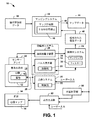
図1は、患者の心臓12の心電図マッピングに利用可能なシステム10の例を示す。システム10は、たとえば診断および/または処置行為の一部として、心臓12の表面または内部に位置する物体の位置決めを、実質的にリアルタイムで行うことができる。たとえば、1つまたは2つ以上の電極16が装着されたペーシングカテーテルなどのカテーテルを、身体14に挿入し、患者の心臓12に心内膜的または心外膜的に接するよう配置可能である。1つまたは2つ以上の電極16を患者の身体14内で配置するのに利用できるさまざまなタイプと構成のペーシングカテーテルおよび電気生理学的(EP)カテーテルについては、当業者であれば理解し、評価するであろう。
FIG. 1 shows an example of a
パルス発生器18は、電極16によって送られる電気信号の印加を制御するよう構成可能である。たとえば、パルス発生器18は、パルス制御部20を含む。このパルス制御部20は、パルス発生器を起動して、電極16とパルス発生器18との間に電気的に接続された導電性リンク26経由で、電極にパルスを供給するよう構成可能である。たとえば、パルス発生器18の出力は、リンク26と模式的に対応するように、電気生理学カテーテルの対応するコネクタに電気的に接続可能である。
The
パルス制御部20は、電極16によって心臓12に電気信号を印加するためのパラメーターを制御できる。この制御パラメーターは、振幅、周波数成分、パルス幅、パルス繰り返し速度、パルス波形を含んでもよい。パルスは、電流パルスとして印加されてもよいし、電圧パルスとして印加されてもよい。また、カテーテルが複数の電極16を含む例では、パルス制御部20は、位置パルスを、異なる電極に異なる時点で、たとえば対応の電気的リンク26を経由するなどして選択的に送信するためのパラメーターを制御可能である。
The
いくつかの例では、パルス発生器18は、位置決めパルスを閾値下パルスとして供給するよう構成可能である。本明細書で使用する場合、「閾値下」という用語は、検知用電極で検出されるノイズより大きく、検知用電極を配して測定できるだけの十分な大きさがあるが、心伝導を刺激する(すなわち、心臓のペーシングのための活動電位を撃発する)ほど大きくはない信号をいう。このように、パルス制御部20は、電極16によって印加される閾値下電気信号の電気的パラメーター(たとえば、パルス振幅、パルス幅、周波数など)を制御可能である。上述したように、閾値下電気信号は、電流パルスとして供給されてもよいし、電圧パルスとして供給されてもよい。
In some examples, the
さらに別の例として、制御部20は、閾値下電気信号を、あらかじめ定められた閾値下振幅(たとえば、約0.5mA)とあらかじめ定められたパルス幅(たとえば、約2ms)とを有する矩形波の電流パルスとして導入してもよい。このパルスの振幅を、心臓のペーシングに必要とされる電流のおよそ25%とすることで、広い安全域を与えつつ、電極のセンサーアレイ22によって身体の表面で測定できるだけの十分に大きな電界を生み出すようにしてもよい。このようにして、アレイ22の体表面センサーの同一アレイで、心臓の電気活動と位置決め信号の両方を検出する。閾値下電気信号の時間幅を、検知用システム24のサンプリング間隔に従って設定し、得られる電界をサンプリング間隔1つあたり少なくとも1回、デジタル的に確実にサンプリングすることができる。たとえば、パルス幅約2msでは、約1,000サンプル/チャネル/秒のサンプリングレートで、確実に少なくとも1つサンプリングをすることができる。閾値下信号は、その振幅が閾値下であっても、その時間幅(たとえば、約2ms)は、心臓のペーシングに通常用いられているものと同一であってもよい。
As yet another example, the
また、パルス制御部20は、検出および信号処理をしやすくするために、センサーアレイ22で検出される対応の電界が、検知用電子装置28および検知用システム24の通過帯域内に残る高周波数成分を含むような方法で、閾値下位置決めパルスを供給してもよい。このように、心電図(EC)マッピング用に患者の身体14で電気信号の測定に用いているものと同一の回路を、閾値下位置決めパルスの検知にも効率良く使用することができる。
In addition, the
もうひとつの例として、パルス制御部20は、複数のカテーテルまたはペーシングリードの表面にある(たとえば、このような各カテーテルまたはリードそれぞれの位置決め用などの)電極への閾値下パルスの送信を制御可能である。すなわち、システム10は、心臓内にある1つまたは2つ以上の物体(たとえば、電極など)の位置決めを行うと同時に、このような物体各々の位置を(たとえば、心電図マップなどに)示すことができる。これは、細長い構造であって、その長さ方向に間隔をおいて設けられた複数の電極を含んでもよい構造(たとえば、カテーテル本体など)に都合良く適用できる。このように、患者の解剖学的形態に対する各電極の位置を検出することで、システム10は、本明細書で開示するように、個々の電極を使用して、患者の解剖学的形態に対する細長い構造の三次元の位置と向きを再構成することができる。電極(または複数の電極)16がある位置は、たとえば、医師が、患者の解剖学的形態に対する電極の位置を前進や後退させる、あるいは調節することなどに応じて、変わってもよい。電極(単数または複数)の位置は、このような移動時の位置決めパルスの検出をもとに、実質的にリアルタイムに更新可能である。
As another example, the
制御部20は、電流および時間幅を他のさまざまな組み合わせにして、閾値下電気信号のパラメーターを制御可能である。たとえば、定電流パルスに代えて、定電圧パルスを使用してもよい。代わりにまたはそれに加えて、閾値下パルスの形状は、方形でなくてもよく、所望の任意の形状(たとえば、正弦、線形または非線形ランプ信号など)にすればよい。
The
もうひとつの例として、パルス制御部20は、パルス発生器18の動作を複数のモードでさらに制御可能である。このモードはたとえば、位置決めモードと治療モードを含んでもよい。位置決めモードでは、パルス制御部20は、パルス発生器18の動作パラメーターを制御して、電極16に位置決め信号を供給することができる。治療モードでは、制御部20は、刺激する(たとえば、ペーシングする)または他の治療(たとえば、アブレーションなど)を心臓12に施すことに応じて、電気信号のパラメーターを制御可能である。あるいは、治療モードでは、外部の別の治療システム30で治療を行っている間、制御部によってパルス発生器18を使用停止にすることができる。この治療には、電気刺激のみならず、非電気タイプの治療(たとえば、化学的処置、温度による処置など)を含んでもよい。このように、制御部20は、その動作を、治療の実施と連携させることができる。
As another example, the
パルス制御部20は、適切なパルスパラメーターを設定し、上述したようなモードのうちの選択したひとつで動作可能である。パルス制御部は、パラメーターを、自動的に設定(たとえば、これらのモードのうちの1つで動作するようパルス制御部をプログラムするなど)、手動で設定(たとえば、ユーザー入力に応答するなど)できるものであってもよいし、自動と手動の制御の組み合わせ(たとえば、半自動など)を用いるものであってもよい。パルス制御部20は、たとえば、治療モードと位置決めモードとを繰り返し切り替えて、位置決めモードの際に求められたような患者14の特定の位置で所望の治療を施しやすくしてもよい。たとえば、センサー情報(たとえば、電極の位置、電気的パラメーターなどを含む)を、位置決めモードの間を含めて連続的に収集し、パルス発生器18に供給可能であり、これに基づいて、制御部20は、治療モードでの治療実施用の刺激パラメーターを調節するためのパラメーターを選択的に調整可能である。
The
さらに別の例として、パルス発生器18は、本明細書で開示する治療システム30など、別個のもうひとつのシステムで電気刺激または別の治療を施している間、たとえば閾値下位置決め信号を経時的に繰り返し供給することによって、位置決めモードだけで動作するよう構成可能である。たとえば、パルス発生器18および検知用電子装置28は、互いに電気的に切り離されて、1つの増幅器システムに統合できる。このように、治療システム30は、治療を施すよう構成された、増幅器システムとは別の電子装置として、実現可能である。本明細書で開示するように、この治療は、電極に対する閾値上パルスによる電気刺激のみならず、他の形態の治療(たとえば、アブレーションなど)を含んでもよい。
As yet another example, the
たとえば、治療システム30は、EPの研究室で見られるような任意のタイプの外部ペースメーカー装置などの、1つまたは2つ以上の電極16で外からペーシングするための心臓刺激装置として実現可能である。治療システム30は、制御部32を含んでもよく、この制御部32は、導電性リンク26を介した電極16に対する閾値上刺激パルスの印加を制御するよう構成されている。このように、リンク26は、1つまたは2つ以上の電極16各々に対するパルスの印加用に、パルス発生器18と治療システム30とで共有可能である。制御部32が、ユーザー入力に応答してこのようなペーシングパルスの電気的パラメーターを制御して、ペーシングパルスを印加(たとえば、スイッチを閉じるなど)してもよいし、このような制御部を、あらかじめ定められたペーシング手順に従って自動化してもよい。閾値上パルスを用いるペーシングまたは他の電気刺激治療の間、閾値上パルスは、刺激治療部位の位置決めを行うための位置決め信号として機能する。
For example, the
もうひとつの例として、治療システム30は、患者の心臓12に非電気的な治療(たとえば、ラジオ波アブレーション、レーザーアブレーション、凍結療法といったアブレーション療法など)を施すよう構成できる。このような例では、電極16は、治療実施メカニズムに固定的に装着されてもよい。制御部20は、閾値下パルスなどの位置決め信号の送信と、治療システム30による治療の実施とを連携させることができる。あるいは、制御部は、治療を施すタイミングと時間的に最も近いパルスを治療実施部位として識別できるように、あらかじめ定められた繰り返し速度に従って閾値下パルスの印加を制御できる。他の例では、システムは、治療を施すタイミングと時間的に最も近い2つの位置決め信号に対する位置の間を内挿できる。非電気的な治療の実施時、閾値下パルスは、治療実施部位の位置決めを行うための位置決め信号として機能できる。たとえば、治療システムの制御部32は、制御部20によって利用されるタイミングパルスを供給し、治療の実施と同時に位置決め信号を供給することができる。代わりにまたはそれに加えて、治療の実施を開始するのに用いられるユーザー入力を、パルス発生器にも供給して、制御部20が治療の実施と同時に位置決め信号を供給できるようにしてもよい。アブレーション療法を適用する場合、注釈(たとえば、アブレーションの時間を含む)を付けてもよく、この注釈は、本明細書で開示するように、治療部位として決定される位置に表示可能である。
As another example, the
図1の例において、センサーアレイ22は、各位置決め信号に対応する電界の検知を含めて、患者の電気活動を記録するのに利用できる1つまたは2つ以上の電極を含んでもよい。一例として、センサーアレイ22は、(たとえば、心電図マッピング法の一部として)患者の心臓に関連した電気活動を測定するために患者の胴の周りに分配された体表面電極の配列に対応してもよい。センサーアレイ22は、(たとえば、患者の胸部を囲む約200を超える電極を持つなど)患者14の胴全体を覆ってもよいし、その選択された領域を覆ってもよい。使用可能な非侵襲センサーアレイの例が、2009年11月10日にファイルされた国際特許出願PCT/US2009/063803号ならびに、米国仮特許出願第61/426,143号(各出願を本明細書に援用する)に図示し、説明されている。
In the example of FIG. 1, the
また、他の例では、電極16によって1つまたは2つ以上のセンサーを実現できる。これは、たとえばEPカテーテルの一部であってもよい。EPカテーテルは、電気活動を心内膜的におよび/または心外膜的に検知するために、患者の身体14および心臓12に挿入可能である。別の例として、センサーアレイ22は、パッチなどの他の器具に設けられた電極の配列であってもよく、これは、患者の心臓上または心臓付近、心内膜および/または心外膜に取り付けることが可能である。これらのパッチは、開胸時および最低侵襲での手技の際に、電気活動を記録するのに利用可能である。このように、EPカテーテルおよび/またはパッチのセンサー電極は、患者の心臓の外側にあるセンサーアレイ22との組み合わせで、異なる観点から同時に患者の心臓12の電気活動を監視するのに利用可能である。
In another example, one or more sensors can be realized by the
図1の例では、センサーアレイ22は、検知された電気情報を、たとえば増幅器システムの一部を形成している検知用電子装置28に供給する。検知用電子装置28は、センサーアレイ22の各センサーによって検出される電気活動の表現に対応する、対応のセンサー信号を供給するための信号処理回路(たとえば、フィルター、増幅器、A/D変換器など)を含んでもよい。対応の検知用電子装置は、たとえば各チャネルで別々に動作可能である。ここで、検知用電極1つあたりチャネル1本として、複数のチャネルがあってもよい。このように、いくつかの例では、センサーアレイ22は、心臓の拍動のたびに複数のセンサー信号を同時に供給でき、このセンサー信号は、パルス発生器18および/または治療システム30によって印加される際に検知される位置決め信号および刺激パルスを含んでもよい。
In the example of FIG. 1, the
検知用電子装置28は、対応のデジタル信号を検知用システム24に供給する。検知用システム24は、電気活動を測定し、かつ、検知された電気データ40を供給するためのデータ取得プロセスを制御するよう構成可能である。検知用システム24は、検知された電気データ40が格納されるサンプルレートを制御し、設定するためのサンプリング制御部34を含んでもよい。サンプルレートは、固定であっても可変であってもよい。また、検知用システム24は、検知用電子装置28からの検知された電気信号を濾波するよう構成されたフィルター36も含んでもよい。たとえば、サンプリング制御部34およびフィルター36は、メモリに格納され、プロセッサーによって実行される、コンピューターで実行可能な命令として実現可能である。たとえば、フィルターの特性が、動作モードに応じて変わってもよい。代わりにまたはそれに加えて、センサー信号は、経路ごとに異なるフィルターの特性を適用できる、互いに平行なフィルター経路に沿って処理可能である。この処理は、各経路を利用して、検知された電気データを異なる目的のために生成できるような方法で行うことが可能である。
The detection electronics 28 supplies a corresponding digital signal to the
一例として、生成された閾値下パルスは、心臓周期とは相関しないため、検知された心臓の信号に重なるキャリア信号と対応することになる。閾値下パルスは高周波数成分を有するため、フィルター36は、検知された電気信号を抽出するための高域通過フィルターとして実現できる。この場合、検知された電気信号は、上記のような閾値下パルスによって(たとえば位置決め時に)生じる電界に起因する。代わりにまたはそれに加えて、閾値下パルスの周波数特性をユーザーが定義でき、これが分かるのであれば、ユーザーが定義した閾値下信号特性に従ってフィルター36を具体的に設計可能である。こうして、得られる濾波後の電気情報を、検知された電気データ40としてメモリーに格納する。閾値下パルスを供給した電極16の位置を決めるのに幾何学形状データと併用できる検知された電気データ40。検知用システム24は、高域通過濾波せずにサンプリング可能な別の信号経路を採用でき、これが、位置決めに用いられる高域通過濾波信号の外にある電気信号の内容(たとえば、心臓の信号など)に対応してもよい。代わりにまたはそれに加えて、他の信号の内容を低域通過濾波して、心臓の信号から位置決めパルスの影響を排除してもよい。本明細書に開示するように、これらの電気信号から検知された電気データ40を処理して、心臓の電気活動に対応する心電図マップを作成することが可能である。
As an example, the generated subthreshold pulse does not correlate with the cardiac cycle and therefore corresponds to a carrier signal that overlaps the detected cardiac signal. Since the subthreshold pulse has a high frequency component, the
検知された電気データ40は、パルス発生器18または治療システム30による電気エネルギーの伝達と同時に取得可能である。たとえば、検知された電気データ40は、電極16の位置を決めるための位置決めデータを含んでもよい。検知された電気データ40の位置決めデータは、センサーアレイ22によって検出される電気活動に対応してもよく、これは、閾値下の位置決め信号に応答してでも、治療時の閾値上刺激信号の印加に応答してでも、あるいは、1つまたは2つ以上の電極16に印加される閾値下信号と閾値上信号の両方に応答してであってもよい。すなわち、適用される治療および各タイプの位置決め信号に対する位置決めデータを利用して電極16の位置を決め、ひいては、患者の身体14内にある治療実施の位置を決めることが可能である。また、検知された電気データ40は、たとえば治療の適用または閾値下パルスの印加なしで、心電図マッピング用に、位置決め信号を使用してまたは使用せずに、他のモードでも取得できる。
The sensed
また、検知用システム24は、それぞれの検知された多チャネル電気データ40と、パルス発生器による印加対象となる電気信号との間の時間的な関係をインデックス化する目的で、クロックを利用して、適当なタイプスタンプ(たとえば、時間インデックスなど)をデータに付加し、その評価および分析を容易にすることができる。また、検知用システム24は、閾値下パルスを自動的にマッピングすることもできる。これは、システム10が、パルスの送信時を厳密にトラッキングできる(たとえば、把握している)からである。
The
また、システム10は、適当なアルゴリズムを適用することで、検知された電気データ40と幾何学形状データ38とを組み合わせ、対応のマップデータ44を与えるようプログラムされたマッピングシステム42を含んでもよい。マップデータ44は、心臓12に関連した電気活動を表してもよい。これはたとえば、患者の心臓12の表面に結合した膜上に分散した、複数の再構成された電位図に対応している。このような、心外膜または心内膜などの心臓の膜上での電気信号のマッピングおよび再構成の実施に利用できる手法の例が、米国特許第6,772,004号および米国特許出願第11/996,441号に開示されており、それぞれの開示内容全体を本明細書に援用する。電気活動は、位置決め時に、患者の身体内でパルス発生器18が(たとえば心臓などに対して)閾値下パルスを印加したのに応答して生じる電界に対応してもよい。代わりにまたはそれに加えて、検知された電気活動は、心臓12自体の自然なおよび/またはペーシングされた電気活動に対応してもよい。これはたとえば、パルス発生器18または治療システム30によって印加される刺激パルスに応答したものであってもよい。
The
別の例として、たとえば、身体の表面に分散されたセンサーによってデータが非侵襲的に取得されるか、心外膜上またはその付近に分散されたセンサーによって侵襲的に取得されたときに、マッピングシステム42は、患者の心臓12の心外膜について、再構成された電位図を表すためのマップデータ44を供給できる。あるいは、マップデータ44は、たとえば患者の心臓のセグメント化された部分(たとえば、左心室および右心室)など、患者の心臓の心内膜表面について、再構成可能である。再構成方法およびは、検知された電気データ40を取得するのに利用する1つ以上の手法(たとえば、非侵襲または侵襲的なセンサーアレイ22など)および幾何学形状データ38の形態に応じて、変わってもよい。
As another example, mapping when, for example, data is acquired non-invasively by sensors distributed on the surface of the body or invasively by sensors distributed on or near the epicardium The
図1の例では、マッピングシステム42は、検知された電気データ40および幾何学形状データ38に基づいてマップデータ44を作成する、マップ作成部46を含む。その例として、マップ作成部46は、電気データ40を処理するようプログラムされた逆アルゴリズムによって電位図の再構成48を実現し、患者の心臓12に結合した、選択された膜上の複数の識別可能な部位の各々についての対応の電位図データを作成可能である。膜は、心外膜の表面、心内膜の表面、または他の幾何学的表面の構造として実施でき、これをマップデータ44で二次元または三次元の膜として表すことが可能である。
In the example of FIG. 1, the
たとえば、幾何学形状データ38は、患者について得られた画像データなど、患者の胴の図形表示の形であってもよい。このような画像処理は、デジタル画像群から解剖学的特徴(1つまたは2つ以上の臓器や他の構造を含む)を抽出・セグメント化することを含んでもよい。また、たとえば、電極が患者に装着されている間に画像を取得し、適当な画像処理(抽出およびセグメント化を含む)によって座標系で電極位置を識別するなどして、センサーアレイ22における電極各々の位置が幾何学形状データ38に含まれていても構わない。こうしてセグメント化された画像データを、患者の着目塊を含む二次元または三次元の図形で表現するよう変換してもよい。
For example, the
その代わりに、幾何学形状データ38は、患者の胴および着目領域(たとえば、心臓など)に対する画像データに基づいて構成された、患者の胴の数学モデルに対応してもよい。センサーアレイ22における電極の位置を含む、適切な解剖学的指標または他の指標を幾何学形状データ38で識別して、電気データ40を対応させやすくして、そこで逆アルゴリズム法を行いやすくしてもよい。このような指標の識別は、(たとえば、画像編集ソフトウェアを使って人間が)手動で実施してもよいし、(たとえば、画像処理技術によって)自動的に実施してもよい。
Alternatively, the
さらに別の例として、幾何学形状データ38は、本明細書で説明するような、対応する表現を構成できる、ほぼどのような画像診断技術を用いて得られる画像データからでも取得できる。画像診断技術の例として、超音波、コンピューター断層撮影(CT)、3D回転撮影(3DRA)、核磁気共鳴イメージング(MRI)、X線、ポジトロン放出断層撮影(PET)、蛍光透視法などがあげられる。このようなイメージングは、検知された電気データ40の生成に用いられる電気活動の記録と同時に実施されてもよいし、イメージングは別に(たとえば、測定データを取得する前または後に)行ってもよい。
As yet another example,
代わりにまたはそれに加えて、幾何学形状データ38は、心臓の通常表示またはカスタム表示(たとえば、モデルなど)に対応してもよい。その心臓は、患者自身の心臓でなくてもよい。このような場合、識別された解剖学的指標に応じて、検知された電気データ40を(たとえば、対応によって)臓器の表示にマッピング可能である。この解剖学的モデルを、信号取得システムと対応させるのに、手動、半自動または自動での対応プロセスを採用することができる。
Alternatively or in addition, the
また、システム10は、患者14内で配置される1つまたは2つ以上の物体の位置を決めるようプログラムされる位置計算部50を含む。図1の例の文脈では、位置計算部50は、マップデータ44の分析に基づいて、位置決め電気信号が印加された位置(たとえば、電極16の位置に対応するなど)を確定することができ、これは、再構成された電位図を含む。この決定は、医師に対して手術中のガイダンスを提供できるよう、リアルタイムで実施されてもよいし、ほぼリアルタイムで実施されてもよい。いくつかの例では、位置のマッピングは、(たとえば、パルスまたはスパイクを選択するためのキャリパーユーザーインターフェース要素などによって)たとえばユーザーが心臓表面上の一組のパルスから閾値下パルスを識別したことに応答して行うなど、手動で実施されてもよい。代わりにまたはそれに加えて、ペーシングパルスのマッピングは、マップデータ44について位置計算部50によって実施されるコンピューター処理をもとにした自動の方法として実現されてもよい。
The
たとえば、マップデータ44が、心臓のユーザー指定の表面上の複数(たとえば、数百または数千)の離散的な位置に対する再構成された電気信号を含む場合、位置計算部50は、マッピングされた電気信号のうち位置決めされた1つを、閾値下信号が適用される絶対位置に対応するものとして選択可能である。別の例として、マップ作成部46は、幾何学形状データ38ならびに、位置決め目的で(たとえば、位置決めモードの間に)高域通過濾波された、検知された電気データ40に基づいて、マップデータ44を作成することも可能である。位置計算部50は、高域通過濾波およびマッピングされた電気信号の振幅の比較をもとに、電極位置に対応する、位置決めされ、再構成された電気信号を選択することが可能である。位置計算部は、高域通過濾波の基準になる位置を決めることができ、これによって再構成された電気信号は、位置決め信号を印加するときに振幅が最大になる。このため、このような、選択され、再構成された電気信号が存在する心臓上の位置は、位置決め信号が印加される電極の位置に対応する。よって、患者の身体14で電極が動いた場合、位置計算部50が、そのような移動と同等の新たな位置情報をコンピューター処理できるように、マップデータ44をアップデートすることが可能である。
For example, if the
また、位置計算部50は、マップデータ44にある再構成された電位図の振幅および興奮到達時間に基づいて、閾値上パルスから位置決めされた、再構成された電位図をコンピューター処理するようプログラム可能である。たとえば、位置計算部50は、再構成された電位図の興奮到達時間が最も早く、振幅が最も大きくなる閾値上パルスが印加される、位置決めによる電極位置を決めることができる。他の例では、位置計算部50は、再構成された電位図の興奮到達時間が最も早く、あるいは、振幅が最も大きくなる閾値上パルスが印加される、位置決めによる電極位置を決めるようプログラム可能である。たとえば、閾値上(たとえば、ペーシング)パルスに対して検出される最も早い興奮到達時間から、電極の位置に対応する心外膜位置を識別可能である。位置決めされた最大値(たとえば、最大振幅)は、ペーシングパルスを印加した心内膜位置に対応してもよい。
The
また、システム10は、位置計算部50によって求められる位置決め情報、マップデータ44またはこれらの組み合わせに基づいて、画面54にグラフィック出力をするよう構成された出力生成部52も含む。このように、画面54は、心臓マップ56を可視表示できる。心臓マップ56は、心臓を図形表現したものを含んでもよく、位置情報に基づいて、位置決め信号が印加された対応の位置で可視的な指標を含んでもよい。一例として、電極位置の可視的な指標は、マップデータ44に基づいて作成される心臓マップ56に重ねられた、グラフィックアイコンであってもよい。マップデータは、位置決め情報だけを含むものとして作成可能である。代わりにまたはそれに加えて、マップデータ44は、心臓に対する(たとえば、自然なおよび/またはペーシングされた)再構成された心臓の電気活動を含んでもよく、位置の可視的な指標を、このような再構成された心臓の電気活動に対応する心臓マップに重ねてもよい。どのタイプの(1つ以上の)電気的なマップデータが心臓マップ56に表示されているかに関わらず、位置計算部50は、実質的にリアルタイムで可視的な指標を更新し、電極16のその時点での位置を反映させることができる。
The
いくつかの例では、出力生成部52は、異なるタイプの被検出信号に対して異なる形の位置決めインジケーターを与えるようプログラム可能である。たとえば、出力生成部52は、第1のタイプの可視的なインジケーターを生成して、心臓に対して移動可能な電極またはカテーテルに対応する移動可能な位置を反映させることが可能である。このように、心臓マップに与えられる第1のタイプの可視的なインジケーターは、心臓に対する電極の移動を反映している。よって、このタイプは、ペーシングまたは他の治療の実施を容易にするなど、ユーザーに、リアルタイムのフィードバックを与えることができる。
In some examples, the
また、出力生成部52は、電極の移動や検知された電気活動の変化とは関係なく、心臓マップに固定したままにできる、第2のタイプの可視的なインジケーターを生成することができる。第2のタイプの可視的なインジケーターは、閾値上ペーシングパルスが印加されたペーシング部位に対応してもよい。このように、出力生成部は、ユーザーが画面54によって容易に得られる各ペーシング部位の好都合な記録を維持できる。また、この第2のタイプの可視的なインジケーターに対する位置情報は、各画像診断技術および幾何学形状データ38における共通の基準マーカーに対する基準に基づいて、別の画像診断法の座標系に自動的に対応できる。たとえば、治療実施位置の指示を、蛍光透視法、X線、2D心エコーまたは3D心エコーなどの別の画像診断技術の画面にレンダリングし、治療を施した位置(たとえば、ペーシング部位またはアブレーション部位など)のそのような画像に、可視的な記録を供給することができる。
The
また、出力生成部52は、ユーザーが、ペーシング位置に対して、たとえば、ペーシング部位が所望の結果を与えていないとユーザーが判断したか否かなど、ユーザー選択された第2のタイプの可視的なインジケーターを選択および削除できるようにするための機構(たとえば、グラフィカルユーザーインターフェースなど)を含んでもよい。代わりにまたはそれに加えて、出力生成部52は、1つまたは2つ以上の電極16にペーシングパルスが印加されたことを検出したのに応答して、心臓マップ56でペーシング部位の可視的なインジケーターを自動的に挿入するようプログラムされたグラフィカルユーザーインターフェースを含んでもよい。この検出は、パルス発生器18または30に供給されるユーザー入力、マップデータ44におけるペーシングパルスの検出またはこれらの組み合わせに応答したものであってもよい。また、出力システムは、グラフィカルユーザーインターフェースを用いたユーザー入力に応答して、心臓マップに提示されたタイプの情報を制御するようプログラム可能である(たとえば、電位マップ、興奮到達マップ、脱分極マップ、同期マップなど)。
The
定位置インジケーターおよび移動可能な位置インジケーターの各々の位置を、たとえばあとで閲覧できるように、マップデータ44と一緒にメモリーに格納してもよい。あるいは、一方または両方のタイプの位置情報は、本明細書に開示したマップデータ44に基づいて、再度コンピューター処理することが可能である。
The position of each of the fixed position indicator and the movable position indicator may be stored in a memory together with the
上述した先の構造的および機能的な特徴に鑑みて、図2を参照して、例示的な方法を一層よく認識することができよう。説明を簡単にするために、図2の例示的な方法は、順次実行されるものとして図示し、説明されているが、他の例のいくつかのアクションが、本明細書に記載したものと異なる順序で、および/または同時に起こり得るため、本実施例は図示の順序に限定されるものではないことは、理解し、評価されたい。この方法は、コンピューター読み取り可能な命令として実現可能であり、その命令はたとえば、揮発性または不揮発性メモリー装置などの非一過性のコンピューター読み取り可能な媒体に格納可能である。媒体中の命令は、処理装置によってさらに実行されてもよい。 In view of the foregoing structural and functional features described above, an exemplary method can be better appreciated with reference to FIG. For ease of explanation, the exemplary method of FIG. 2 has been illustrated and described as being performed sequentially, but some actions of other examples are as described herein. It should be understood and appreciated that the embodiments are not limited to the order shown because they can occur in different orders and / or simultaneously. The method can be implemented as computer-readable instructions that can be stored on a non-transitory computer-readable medium, such as, for example, a volatile or non-volatile memory device. The instructions in the medium may be further executed by a processing device.
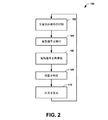
図2は、本明細書に開示したように、患者において物体の位置決めを行うのに用いることが可能な方法100の例を示す流れ図である。たとえば、方法100は、1つまたは2つ以上の電極(たとえば、図1の電極16など)を含むカテーテルまたはペーシングリードを使用するなどして、低侵襲または最小限の侵襲で、患者の心臓を施術する場合に行うことが可能である。たとえば、カテーテル挿入法は、心臓再同期療法(CRT)、心臓アブレーションまたは他の同様のタイプの施術をする目的で行うことができる。このような施術の間、方法100は、カテーテルの位置決めを行うよう実現可能である。また、方法100は、たとえばCRT装置またはペースメーカーからの1本または2本以上のペーシングリードの位置決めを行うのに利用可能である。
FIG. 2 is a flow diagram illustrating an example of a
方法100は、位置決めの適用が制御される102から開まる。たとえば、電極を有するカテーテルを患者の心臓まで前進させることができ、閾値下電気信号を(たとえば、図1のパルス発生器18によるなどして)印加して、対応する電界を患者の体内で発生させることが可能である。閾値下信号は、本明細書に開示されているように、幅と周波数が制御された電流パルスまたは電圧パルスとして生成可能である。あるいは、位置決め信号は、患者内の導電性経路を刺激できるだけの十分な振幅を有する閾値上電気信号として実現可能である。この制御は、自動であってもよいし、ユーザー入力に応答してなされるものであってもよい。
The
104では、電気信号を検知可能である。たとえば、センサーの配列(たとえば、センサーアレイ22)を患者の胴に分散させ、102で印加された閾値下電気信号に対応する電気信号を含む身体表面の電位を、非侵襲的に検知可能である。検知された電気信号を、アナログ処理およびデジタル処理してもよい。たとえば、信号を(たとえば高域通過フィルターによって)濾波し、位置決め信号によって生じた電界に対応する周波数成分のみならず、心臓の自然な電気活動またはペーシングされた電気活動に対応する成分を通過させてもよい。処理後の信号は、検知された電気データ(たとえば、図1のデータ40など)として、メモリーに格納可能である。センサーは、身体全体の表面またはその選択された一部で身体表面の電位を同時に検出できるため、本明細書に開示された方法およびシステムは、電極を、三次元空間で絶対位置に位置決めでき、その電極を利用して他の心臓の電気活動を同時に表示することもできる。
At 104, an electrical signal can be detected. For example, an array of sensors (eg, sensor array 22) can be dispersed in the patient's torso and body surface potentials including electrical signals corresponding to the subthreshold electrical signals applied at 102 can be detected non-invasively. . The detected electrical signal may be subjected to analog processing and digital processing. For example, the signal may be filtered (eg, by a high pass filter) to pass not only the frequency component corresponding to the electric field produced by the positioning signal, but also the component corresponding to the heart's natural or paced electrical activity. Also good. The processed signal can be stored in memory as detected electrical data (eg,
106では、検知された電気信号は、心臓の膜上で(たとえば、図1のマッピングシステム42によって)電気信号を再構成するのに利用される。この膜はたとえば、心内膜の表面、心外膜の表面または他の心臓の膜であってもよい。たとえば、106でのマッピングは、幾何学形状データおよび検知された電気データに基づいて、非侵襲的に測定された身体表面の電位を心臓の電気活動データに変換するアルゴリズムを用いて実現可能である。
At 106, the sensed electrical signal is utilized to reconstruct the electrical signal on the heart membrane (eg, by mapping
108では、方法100は、106で供給された、再構成された電気信号の分析をもとに、閾値下パルスが印加された位置を決めることを含む。一例として、この位置は、位置決め信号が印加された絶対位置に対応する、位置決めされたマッピング信号を選択することによって、求められる。このような位置決めされたマッピング信号は、心臓の表面にマッピングされた、複数の再構成された電気信号から選択可能である。電極位置に対する位置決めされたマッピング信号は、振幅が最大の信号であってもよく、102で印加される閾値下パルスの周波数に対応する周波数特性を有してもよい。あるいは、位置決めされたマッピング信号は、興奮到達時間および振幅に基づいて、再構成された電位図から選択される閾値上パルスの位置に対応してもよい。
At 108, the
110では、(たとえば、図1の出力生成部52によって)出力を生成可能である。この出力は、心臓を図形表現(たとえば、画像表現)したものを含むものとして与えることが可能であり、これは、(たとえば、位置決めされたマッピング信号に対応する)位置決め信号が電極によって心臓に印加された位置に、可視的なインジケーターを含む。この方法100を手術中に繰り返し、患者の心臓に対してカテーテルをガイドしやすくすることが可能であり、心臓に対して電極が移動すると、この方法では、実質的にリアルタイムに出力を更新し、その時点での電極の位置を反映することが可能である。さらなる心臓の電気活動(自然なおよび/またはペーシングされた)も、電極の位置に重ねてこれと同時に表示可能であり、ユーザーをさらに支援できる。たとえば、あらゆるタイプの不整脈(限局性不整脈またはリエントリー性不整脈)のみならず、洞律動の障害を治療するための治療法(たとえば、ペーシングおよび/またはアブレーションなど)の適用と併用して、カテーテルの位置決めのために、この位置決め方法を利用できる。
At 110, an output can be generated (eg, by the
図3は、本明細書に開示されたシステムおよび方法によって生成可能な画面200(たとえば、グラフィカルユーザーインターフェースなど)の例を示す。図3の例では、画面200は、選択された時点での電位に対応する電位マップ204を重ねて表示された、心臓202を図形表現したものを含む。この時点は、グラフィカルユーザーインターフェースを用いてユーザーが選択してもよいし、(たとえば、このようなパルスを含む時間を保証するための信号処理技術を用いて)自動的に選択することも可能である。たとえば、この時点は、心臓に位置決めパルスを印可する時点に対応してもよい。画面には、閾値下パルスによって生じる電界に対応する心臓の電気活動信号(たとえば、図1のマッピングシステム42によって心臓にマッピングされた電位の電気的トレースなど)のプロット206も含む。
FIG. 3 illustrates an example of a screen 200 (eg, a graphical user interface, etc.) that can be generated by the systems and methods disclosed herein. In the example of FIG. 3, the
図3の例では、電界は、閾値下パルスとして供給された位置決め信号に対応する。これは、(たとえば、信号を加えることで)心臓の電気活動によって生じる信号に重畳される。さらに、心臓の電気活動から閾値下パルスの電界を分離するための信号処理を実施し、このような信号を画面200に表示してもよい。この画面には、ユーザー入力に応答して起動できる映画モードを含んでもよい。映画モードでは、画面200の電位マップ204が、時間の関数として変化してもよく、これは、フォワード、リバース、ループまたは他のユーザーが選択した時間的な方法で進行させることが可能である。
In the example of FIG. 3, the electric field corresponds to a positioning signal supplied as a subthreshold pulse. This is superimposed on the signal produced by the heart's electrical activity (eg, by applying a signal). Further, signal processing may be performed to separate the electric field of the subthreshold pulse from the electrical activity of the heart, and such a signal may be displayed on the
グラフィックプロット206での再構成された電位図に対応する閾値下パルスは、画面200では、この画面右側の第1、第2、第4のトレースに表示される。図3の例では、スパイクが最大の再構成された電位図が、210で示されている。これらの再構成された電気的位置決めパルスは各々、ユーザーによって、ユーザーインターフェースを介して電位図プロットと識別可能であるし、自動の検出方法によって、下にある再構成された電位図データと識別可能である。領域212で示したマップの中央部分は、位置決めされた最大値210に対応する、電気信号の最も高い電位を示す。これは、位置計算部によって、この位置決めフィールドを発生しているカテーテルの位置に対応するものとして(たとえば、カテーテル上の電極を用いて)識別可能である。このように、閾値下位置決め信号が印加された心臓表面上の位置を識別するために、画面内で、可視的なインジケーター214を、識別された領域212の重心にレンダリング可能である。また、画面200は、表示されるマップデータの解釈を容易にするとともに、特定の座標系で心臓の再配列を可能にするためのGUIの特徴とスケールとを含んでもよい。
The subthreshold pulses corresponding to the reconstructed electrogram in the
図4は、本明細書に開示されたシステムおよび方法によって生成可能な別の画面250(たとえば、グラフィカルユーザーインターフェースなど)の例を示す。図4の例では、画面250は、選択された時点での再構成された電気信号に対応する電位マップが上に表示された心臓252を図形表現したものを含む。図4の例では、再構成された電気信号は、電極を介して印加される閾値上刺激信号(たとえば、ペーシング信号など)に基づいている。また、画面250は、心臓252上にマップを作成するのに利用される再構成された電気信号のプロット254も含む。振幅が最も高く興奮到達時間が最も早い領域を256で識別し、閾値上位置決め信号が印加される電極の位置を表す。
FIG. 4 illustrates an example of another screen 250 (eg, a graphical user interface, etc.) that can be generated by the systems and methods disclosed herein. In the example of FIG. 4, the
また、画面は、心臓マップ252の向きを示す心臓のGUI要素258も含む。このため、ユーザーは、心臓のGUI要素を回転させ、これに応じて心臓マップ252も回転させるのに、ポインティングデバイス(たとえば、マウス)または他のユーザー入力装置を用いることができる。また、画面には、心臓マップ252上に提示されるカラーコードの指標を与えることができるスケール260を含む。これはたとえば、興奮到達時間に対応するものであってもよい。
The screen also includes a
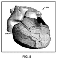
図5は、心臓カテーテル272を図形表現したものが心臓の画像上に重ねられた、心臓の例示的なECマップ270を示す。例示的なカテーテルが、2つの電極274を含んで図示されているが、図示のカテーテルは電極をいくつ含んでもよく、たとえば、治療の実施時にユーザーに使用される実際のカテーテルデザインと同じであってもよいことを、理解されたい。たとえば、ユーザーは、(たとえば、製造者および型番によって)カテーテルのタイプおよび構成を識別でき、たとえば、これをグラフィカルユーザーインターフェースによって提供される一覧から選択できる。このように、システムは、画面において、本明細書に開示された手法に基づいて求められた位置で、選択されたタイプと構成のカテーテルを、グラフィカルに提示することができる。カテーテル272の位置は、患者の身体に挿入された実際のカテーテルの位置決め信号(閾値下電気信号および/または閾値上電気信号)が電極に供給されたことに応答して、電極274の一方または両方の位置を決めることで、心臓マップ270上で決定および提示できる。心臓に対するカテーテルの移動も同様に、トラッキングしてマップ270に表示可能である。
FIG. 5 shows an
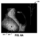
図6Aおよび図6Bは、それぞれ、特定の閾値上位置決め(たとえば、ペーシング)パルスが印加されたことに応答して求められた、位置決めされた解剖学的位置294および296を示す心電図マップ290および292の例を示す。対応の位置294は、それぞれの興奮到達時間に基づいて、再構成された電位図からコンピューターで計算される心外膜の興奮の心内膜上の投影に対応する。このように、図6Aに示されるように、マップは、心臓に対する興奮マップを示し、位置294は、最も早い興奮の中心に対応する。もう1つの位置296を、比較目的で、図6Aに示す。位置296は、図6Bに示されるように、再構成された電位図からコンピューターで計算された、位置決めされた振幅最大に基づいて求められる心内膜の位置に対応する(たとえば、図6Bに示す)。図6Aおよび図6Bは、それぞれのマップ290および292の作成に、信号のどの部分を利用するかを示すタイミングキャリパーとともに、位置294および296を計算するもとになった電位図を示す。たとえば、興奮マップ290は、心臓組織の伝導についての興奮到達時間に基づいて、作成される。電位マップ292は、マップを作成することで、ペーシング部位に対応する、対応の心内膜位置を識別する極大値を決定するのに利用される閾値上パルスを示す。
FIGS. 6A and 6B show electrocardiographic maps 290 and 292 showing positioned
上記の構造的または機能的な説明に鑑みて、本発明の一部を、方法、データ処理システムまたはコンピュータープログラム製品として実施してもよいことは、当業者であれば自明であろう。したがって、本発明のこのような一部は、完全にハードウェアの実施形態、完全にソフトウェアの実施形態あるいは、図7のコンピューターシステムで図示し、説明するような、ソフトウェアとハードウェアとを組み合わせた実施形態の形をとってもよい。さらに、本発明の一部が、媒体にコンピューター読み取り可能なプログラムコードを有する、コンピューター使用可能な記憶媒体上のコンピュータープログラム製品であってもよい。好適なコンピューター読み取り可能な媒体であれば、どのようなものを利用してもよく、一例として、静的記憶装置および動的記憶装置、ハードディスク、光学記憶装置および磁気記憶装置があげられるが、これらに限定されるものではない。 In view of the above structural or functional description, it will be apparent to those skilled in the art that portions of the present invention may be implemented as a method, data processing system, or computer program product. Accordingly, such portions of the present invention may be a fully hardware embodiment, a fully software embodiment, or a combination of software and hardware as illustrated and described in the computer system of FIG. It may take the form of an embodiment. Further, part of the present invention may be a computer program product on a computer usable storage medium having the computer readable program code on the medium. Any suitable computer readable medium may be used, examples of which include static and dynamic storage devices, hard disks, optical storage devices and magnetic storage devices. It is not limited to.
本明細書では、方法、システムおよびコンピュータープログラム製品のブロック図を参照して、本発明の特定の実施形態についても説明してきた。図示のブロックならびに、図示のブロックの組み合わせを、コンピューターで実行可能な命令によって実装してもよいことは、理解できよう。これらのコンピューターで実行可能な命令を、汎用コンピューター、専用コンピューターあるいは、マシンを製造するための他のプログラム可能なデータ処理装置(または装置と回路の組み合わせ)の1つまたは2つ以上のプロセッサーに対して、プロセッサーによって実行する命令が1つまたは複数のブロックに示される機能を実装するように供給してもよい。 Certain embodiments of the present invention have also been described herein with reference to block diagrams of methods, systems and computer program products. It will be understood that the illustrated blocks, as well as combinations of the illustrated blocks, may be implemented by computer-executable instructions. These computer-executable instructions are sent to one or more processors in a general-purpose computer, a dedicated computer, or other programmable data processing device (or combination of devices and circuits) for manufacturing a machine. Thus, instructions executed by the processor may be provided to implement the functionality indicated in one or more blocks.
これらのコンピューターで実行可能な命令は、コンピューターまたは他のプログラム可能なデータ処理装置を、コンピューター読み取り可能なメモリーに格納された命令が、フローチャートの1つまたは複数のブロックに示される機能を実装する命令を含む製品につながるように、特定の方法で機能させることのできるコンピューター読み取り可能なメモリーに格納されてもよい。また、コンピュータープログラムの命令を、コンピューターまたは他のプログラム可能なデータ処理装置にロードして、このコンピューターまたは他のプログラム可能な装置に一連の動作ステップを実施させ、コンピューターまたは他のプログラム可能な装置上で実行する命令によって、フローチャートの1つまたは複数のブロックに示される機能を実装するためのステップが得られるように、コンピューターで実装されるプロセスを生成してもよい。 These computer-executable instructions are instructions that cause a computer or other programmable data processing device to implement the functionality in which instructions stored in computer-readable memory are shown in one or more blocks of the flowchart. May be stored in a computer readable memory that can be operated in a specific manner to lead to products containing. The computer program instructions can also be loaded into a computer or other programmable data processing device to cause the computer or other programmable device to perform a series of operational steps on the computer or other programmable device. A computer-implemented process may be generated such that the instructions executed in step 1 provide steps for implementing the functionality shown in one or more blocks of the flowchart.
この点に鑑みて、図7は、本発明の1つまたは2つ以上の実施形態を実行するのに用いることのできるコンピューターシステム300の一例を示す。これらの実施形態は、たとえば、センサーデータの取得および処理、画像データの処理のみならず、心臓の電気活動の解析に関連した、変換されたセンサーデータおよび画像データの解析を含む。コンピューターシステム300は、1つまたは2つ以上のネットワーク接続された汎用コンピューターシステム、組込型のコンピューターシステム、ルーター、スイッチ、サーバー装置、クライアント装置、さまざまな中間装置/ノードまたはスタンドアロンのコンピューターシステムに実装可能なものである。また、コンピューターシステム300は、たとえば、携帯情報端末(PDA)、ラップトップコンピューター、ポケットベルなどのさまざまなモバイルクライアントに、それが十分な処理能力を持つという前提で、実装可能なものである。
In this regard, FIG. 7 illustrates an example of a
コンピューターシステム300は、処理装置301と、システムメモリー302と、さまざまなシステム構成要素(システムメモリーを含む)を処理装置301に接続するシステムバス303とを含む。デュアルマイクロプロセッサーなどのマルチプロセッサーアーキテクチャを、処理装置301として使用してもよい。システムバス303は、多岐にわたるバスアーキテクチャーのうちのいずれかを用いる、メモリーバスまたはメモリーコントローラー、周辺機器用バス、ローカルバスをはじめとするさまざまなタイプのバス構造のうち、どのようなものであってもよい。システムメモリー302は、リードオンリーメモリー(ROM)304と、ランダムアクセスメモリー(RAM)305とを含む。コンピューターシステム300内の要素間で情報を転送しやすくする基本ルーチンを含むROM 304に、基本入出力システム(BIOS)306を常駐させることが可能である。
The
コンピューターシステム300は、たとえば、ハードディスクドライブ307と、リムーバブルディスク309との間で読み書きするための磁気ディスクドライブ308と、たとえばCD−ROMディスク311を読み取ったり、他の光学媒体との間で読み書きしたりするための光ディスクドライブ310と、を含んでもよい。ハードディスクドライブ307、磁気ディスクドライブ308、光ディスクドライブ310はそれぞれ、ハードディスクドライブインターフェース312、磁気ディスクドライブインターフェース313、光ドライブインターフェース314を介して、システムバス303に接続されている。ドライブと、これに付属するコンピューター読み取り可能な媒体は、コンピューターシステム300用のデータ、データ構造、コンピューターで実行可能な命令を格納する不揮発性の記憶装置となる。上述したコンピューター読み取り可能な媒体の説明では、ハードディスク、リムーバブル磁気ディスク、CDについて言及したが、この動作環境で、磁気カセット、フラッシュメモリーカード、デジタルビデオディスクなど、さまざまな形態でのコンピューターで読み取り可能な他のタイプの媒体を使用してもよい。さらに、このような媒体のいずれも、本発明の1つまたは2つ以上の部分を実装するためのコンピューターで実行可能な命令を含むものであってもよい。
The
多数のプログラムモジュールを、ドライブおよびRAM 305に格納してもよい。RAM 305は、オペレーティングシステム315、1つまたは2つ以上のアプリケーションプログラム316、他のプログラムモジュール317、プログラムデータ318を含む。たとえばアプリケーションプログラム316と、プログラムデータは、本明細書にて図示し、説明するような1つまたは2つ以上のセンサーからの電気データを取得し、処理し、表示するようプログラムされる機能および方法を含んでもよい。アプリケーションプログラム316は、たとえば、図1の検知用システム24、マッピングシステム42、位置計算部50、出力生成部52の機能を実行するようプログラムされる機能および方法を含んでもよい。図1の検知された電気データ40、幾何学形状データ38、マップデータ44は、たとえば、メモリー302および307に格納可能である。さらに、アプリケーションプログラムおよびプログラムデータは、図2の方法を実行し、図3から図6を参照して開示したような出力を生成するようプログラムされる機能および方法を含んでもよい。
Multiple program modules may be stored in the drive and
ユーザーは、1つまたは2つ以上の入力装置320を介して、コマンドおよび情報をコンピューターシステム300に入力してもよい。入力装置320は、たとえば、ポインティングデバイス(たとえば、マウス、タッチスクリーンなど)、キーボード、マイク、ジョイスティック、ゲームパッド、スキャナなどである。たとえば、ユーザーは、ドメインモデルを編集または修正するのに、入力装置320を用いることができる。これらの入力装置および他の入力装置320は、システムバスに接続された対応のポートインターフェース322を介して処理装置301に接続されることが多いが、パラレルポート、シリアルポートまたはユニバーサルシリアルバス(USB)などの他のインターフェースを介して接続されることもある。1つまたは2つ以上の出力装置324(たとえば、ディスプレイ、モニター、プリンター、プロジェクターまたは他のタイプの表示装置など)も、ビデオアダプターなどのインターフェース326を介してシステムバス303に接続される。
A user may enter commands and information into the
コンピューターシステム300は、リモートコンピューター328などの1台または2台以上のリモートコンピューターとの論理接続を使用して、ネットワーク環境で動作することもある。リモートコンピューター328は、ワークステーション、コンピューターシステム、ルーター、ピアデバイスまたは他の一般的なネットワークノードであってもよく、一般に、コンピューターシステム300に関して説明した多くの要素またはすべての要素を含む。330で概略的に示す論理接続は、ローカルエリアネットワーク(LAN)およびワイドエリアネットワーク(WAN)を含むものであってもよい。
LANネットワーク環境で用いる場合、コンピューターシステム300を、ネットワークインターフェースまたはアダプター332を介してローカルネットワークに接続することができる。WANネットワーク環境で用いる場合、コンピューターシステム300は、モデムを含むものであってもよいし、LAN上の通信サーバーに接続されてもよい。内蔵式であっても外付けであってもよいモデムを、適当なポートインターフェース経由でシステムバス303に接続することができる。ネットワーク環境では、コンピューターシステム300との関連で示したアプリケーションプログラム316またはプログラムデータ318あるいはこれらの一部を、リモートメモリー記憶装置340に格納してもよい。
When used in a LAN networking environment, the
上記にて説明してきたものは、例である。もちろん、構成要素または方法論の想定できるあらゆる組み合わせを説明するのは不可能であるが、上記以外の組み合わせや順序が可能であることは、当業者であれば認識するであろう。したがって、本発明は、添付の特許請求の範囲を含めて本出願の範囲内に入る、このような変更、修飾、改変をすべて包含することを意図したものである。本明細書で使用する場合、「含む」という表現は、含むことを意味するが、これに限定されるものではなく、「含んで」という表現は、含んでいることを意味するが、これに限定されるものではない。「基づく」という表現は、少なくともある程度は基づいていることを意味する。また、開示または特許請求の範囲で「不定冠詞a」「不定冠詞an」「第1の」または「もうひとつの」要素またはその等価物について言及する場合、それは、2つまたは3つ以上のこのような要素を必要とすることも排除することもなく、1つまたは2つ以上のこのような要素を含むものと解釈されるべきである。 What has been described above is an example. Of course, it is impossible to describe every possible combination of components or methodologies, but those skilled in the art will recognize that other combinations and orders are possible. Accordingly, the present invention is intended to embrace all such alterations, modifications and variations that fall within the scope of this application, including the appended claims. As used herein, the expression “including” means including, but not limited to, the expression “including” means including, It is not limited. The expression “based on” means based at least in part. Also, when an indefinite article a, an indefinite article an, a "first" or "another" element or equivalent thereof is referred to in the disclosure or in the claims, it means that two or more of this Such elements are not required or excluded and should be construed to include one or more such elements.
Claims (12)
前記電界に対応する電気信号の検知に基づいて、検知された電気データをメモリーに格納し、
解剖学的形態と、前記電界の検出に用いられる複数のセンサーとの幾何学的関係を表す幾何学形状データを前記メモリーに格納し、
前記幾何学形状データおよび前記検知された電気信号に基づいて、前記組織に対する解剖学的な膜で、電気信号を再構成し、
前記再構成された電気信号を分析して、前記再構成された電気信号各々の振幅と周波数特性とを、前記位置決め信号に関し比較することに基づいて、前記位置決め信号が印加された絶対位置を決めること
を含む、物体の位置決めを行うためのシステムの作動方法であって、
前記位置決め信号は、前記患者の組織において活動電位を発生させるには不十分である閾値下電気信号を含む、方法。 In order to generate an electric field in the patient's tissue, the positioning signal supplied to the electrode coupled to the object is controlled,
Based on the detection of the electrical signal corresponding to the electric field, the detected electrical data is stored in a memory,
Storing geometric shape data representing a geometric relationship between an anatomical form and a plurality of sensors used for detecting the electric field in the memory;
Reconstructing an electrical signal with an anatomical membrane for the tissue based on the geometry data and the sensed electrical signal;
Analyzing the reconstructed electrical signal and determining an absolute position to which the positioning signal is applied based on comparing the amplitude and frequency characteristics of each of the reconstructed electrical signals with respect to the positioning signal. A method of operating a system for positioning an object, comprising:
The positioning signal comprises a subthreshold electrical signal that is insufficient to generate an action potential in the patient's tissue.
前記分析することは、前記絶対位置に対応する、位置決めされたマッピング信号を選択することをさらに含む、請求項1に記載の方法。 The reconstructed electrical signal corresponds to a plurality of reconstructed electrical signals at respective locations across the surface of the patient's heart;
The method of claim 1, wherein the analyzing further comprises selecting a positioned mapping signal corresponding to the absolute position.
前記再構成された電気信号に基づいて、前記患者の心臓の心電図マップを作成すること
をさらに含み、
前記インジケーターは、前記患者の心臓の前記心電図マップに重ねられる、請求項1に記載の方法。 Generating output data to provide a graphic screen of the patient's heart, including an indicator at the position to which the positioning signal is applied;
Generating an electrocardiogram map of the patient's heart based on the reconstructed electrical signal;
The method of claim 1, wherein the indicator is superimposed on the electrocardiogram map of the patient's heart.
前記インジケーターが、前記患者の心臓に対する前記電極の移動に応じて前記心臓の前記グラフィック画面内で移動可能であるような方法で、前記決定された位置に従って、前記インジケーターの表示位置を調節すること
をさらに含む、請求項4に記載の方法。 Analyzing the reconstructed electrical signal generated in response to each application of the positioning signal to determine the position at which the positioning signal was applied;
Adjusting the display position of the indicator according to the determined position in such a manner that the indicator is movable within the graphic screen of the heart in response to movement of the electrode relative to the patient's heart. The method of claim 4 further comprising:
前記位置決め信号は、前記患者の心臓の心臓周期と無相関である、請求項1に記載の方法。 Further comprising high-pass filtering the sensed electrical signal and extracting a signal component corresponding to the electric field generated in response to the positioning signal;
The method of claim 1, wherein the positioning signal is uncorrelated with a cardiac cycle of the patient's heart.
前記再構成された電気信号に基づいて、前記患者の心臓の心電図マップを作成し、
前記心電図マップ上に、前記位置決め信号が印加された前記位置で、カテーテルまたはペーシングリードに対応する可視的なインジケーターを作成すること
をさらに含み、
前記電極は、前記ペーシングリードまたはカテーテルに固定されるか、その一部であり、
前記可視的なインジケーターは、前記心電図マップに重なっている、請求項1に記載の方法。 Detecting the electrical signal by the plurality of sensors;
Creating an electrocardiogram map of the patient's heart based on the reconstructed electrical signal;
Further comprising creating a visual indicator on the electrocardiogram map corresponding to a catheter or pacing lead at the location where the positioning signal is applied;
The electrodes may either be fixed to the pacing lead or catheter, a portion thereof,
The method of claim 1, wherein the visible indicator overlaps the electrocardiogram map.
前記閾値下電気信号は、自動制御信号に応答してパルス発生器によって供給され、
前記閾値上電気信号は、ユーザー入力に応答して印加される、請求項1〜10のいずれか1項に記載の方法。 The positioning signal comprises a combination of sub-threshold and over-threshold electrical signals applied at different times;
The subthreshold electrical signal is provided by a pulse generator in response to an automatic control signal ;
11. A method according to any one of the preceding claims, wherein the over-threshold electrical signal is applied in response to user input .
ユーザー入力に応答して、閾値上電気信号を印加し、
再構成された電気信号を分析して、前記閾値上電気信号が供給された位置を決定し、
出力データを生成して、前記閾値上電気信号が供給された位置でのグラフィックインジケーターを含む前記患者の心臓のグラフィックな画面を与え、
前記再構成された電気信号を基に前記患者の心臓の心電図マップを作成すること、を含み、
前記グラフィックインジケーターは、前記患者の心臓に対して定位置に、前記患者の心臓の心電図に重ねられる、請求項1に記載の方法。 The method of claim 1, further comprising:
In response to user input, apply an electrical signal above the threshold,
Analyzing the reconstructed electrical signal to determine the location at which the electrical signal above the threshold was supplied ;
Generating output data to provide a graphical screen of the patient's heart that includes a graphic indicator at a position where the over-threshold electrical signal is supplied ;
Creating an electrocardiogram map of the patient's heart based on the reconstructed electrical signal;
The method of claim 1, wherein the graphic indicator is superimposed on an electrocardiogram of the patient's heart in a fixed position relative to the patient's heart.
Applications Claiming Priority (3)
| Application Number | Priority Date | Filing Date | Title |
|---|---|---|---|
| US201161504547P | 2011-07-05 | 2011-07-05 | |
| US61/504,547 | 2011-07-05 | ||
| PCT/US2012/045582 WO2013006713A2 (en) | 2011-07-05 | 2012-07-05 | Localization for electrocardiographic mapping |
Publications (2)
| Publication Number | Publication Date |
|---|---|
| JP2014523776A JP2014523776A (en) | 2014-09-18 |
| JP6139518B2 true JP6139518B2 (en) | 2017-05-31 |
Family
ID=47437696
Family Applications (1)
| Application Number | Title | Priority Date | Filing Date |
|---|---|---|---|
| JP2014519299A Expired - Fee Related JP6139518B2 (en) | 2011-07-05 | 2012-07-05 | Positioning for ECG mapping |
Country Status (5)
| Country | Link |
|---|---|
| US (1) | US10506948B2 (en) |
| EP (1) | EP2729064A4 (en) |
| JP (1) | JP6139518B2 (en) |
| CA (1) | CA2841388A1 (en) |
| WO (1) | WO2013006713A2 (en) |
Families Citing this family (98)
| Publication number | Priority date | Publication date | Assignee | Title |
|---|---|---|---|---|
| US8784336B2 (en) | 2005-08-24 | 2014-07-22 | C. R. Bard, Inc. | Stylet apparatuses and methods of manufacture |
| US8388546B2 (en) | 2006-10-23 | 2013-03-05 | Bard Access Systems, Inc. | Method of locating the tip of a central venous catheter |
| US7794407B2 (en) | 2006-10-23 | 2010-09-14 | Bard Access Systems, Inc. | Method of locating the tip of a central venous catheter |
| ES2651898T3 (en) | 2007-11-26 | 2018-01-30 | C.R. Bard Inc. | Integrated system for intravascular catheter placement |
| US10449330B2 (en) | 2007-11-26 | 2019-10-22 | C. R. Bard, Inc. | Magnetic element-equipped needle assemblies |
| US10524691B2 (en) | 2007-11-26 | 2020-01-07 | C. R. Bard, Inc. | Needle assembly including an aligned magnetic element |
| US8849382B2 (en) | 2007-11-26 | 2014-09-30 | C. R. Bard, Inc. | Apparatus and display methods relating to intravascular placement of a catheter |
| US9649048B2 (en) | 2007-11-26 | 2017-05-16 | C. R. Bard, Inc. | Systems and methods for breaching a sterile field for intravascular placement of a catheter |
| US8781555B2 (en) | 2007-11-26 | 2014-07-15 | C. R. Bard, Inc. | System for placement of a catheter including a signal-generating stylet |
| US10751509B2 (en) | 2007-11-26 | 2020-08-25 | C. R. Bard, Inc. | Iconic representations for guidance of an indwelling medical device |
| US9521961B2 (en) | 2007-11-26 | 2016-12-20 | C. R. Bard, Inc. | Systems and methods for guiding a medical instrument |
| ES2525525T3 (en) | 2008-08-22 | 2014-12-26 | C.R. Bard, Inc. | Catheter assembly that includes ECG and magnetic sensor assemblies |
| US8437833B2 (en) | 2008-10-07 | 2013-05-07 | Bard Access Systems, Inc. | Percutaneous magnetic gastrostomy |
| US8103338B2 (en) | 2009-05-08 | 2012-01-24 | Rhythmia Medical, Inc. | Impedance based anatomy generation |
| US8571647B2 (en) | 2009-05-08 | 2013-10-29 | Rhythmia Medical, Inc. | Impedance based anatomy generation |
| EP3542713A1 (en) | 2009-06-12 | 2019-09-25 | Bard Access Systems, Inc. | Adapter for a catheter tip positioning device |
| US9532724B2 (en) | 2009-06-12 | 2017-01-03 | Bard Access Systems, Inc. | Apparatus and method for catheter navigation using endovascular energy mapping |
| CN102665541B (en) | 2009-09-29 | 2016-01-13 | C·R·巴德股份有限公司 | The probe used together with the equipment that the Ink vessel transfusing for conduit is placed |
| ES2811107T3 (en) | 2010-02-02 | 2021-03-10 | Bard Inc C R | Apparatus and method for catheter conduction and tip localization |
| CA2800813C (en) | 2010-05-28 | 2019-10-29 | C.R. Bard, Inc. | Apparatus for use with needle insertion guidance system |
| EP2575611B1 (en) | 2010-05-28 | 2021-03-03 | C. R. Bard, Inc. | Apparatus for use with needle insertion guidance system |
| KR101856267B1 (en) | 2010-08-20 | 2018-05-09 | 씨. 알. 바드, 인크. | Reconfirmation of ecg-assisted catheter tip placement |
| EP2632360A4 (en) | 2010-10-29 | 2014-05-21 | Bard Inc C R | Bioimpedance-assisted placement of a medical device |
| US9757044B2 (en) | 2011-03-10 | 2017-09-12 | Acutus Medical, Inc. | Device and method for the geometric determination of electrical dipole densities on the cardiac wall |
| KR20140051284A (en) | 2011-07-06 | 2014-04-30 | 씨. 알. 바드, 인크. | Needle length determination and calibration for insertion guidance system |
| CA2881462C (en) | 2012-08-09 | 2020-07-14 | University Of Iowa Research Foundation | Catheters, catheter systems, and methods for puncturing through a tissue structure |
| US9895079B2 (en) * | 2012-09-26 | 2018-02-20 | Biosense Webster (Israel) Ltd. | Electropotential mapping |
| WO2014113892A2 (en) * | 2013-01-24 | 2014-07-31 | Dalhousie University | Computer-aided localization of site of origin of cardiac activation with discriminator leads |
| CN105324067B (en) | 2013-05-06 | 2017-10-24 | 波士顿科学医学有限公司 | Continuous display of recent beat characteristics during real-time or playback electrophysiological data visualization |
| US9918649B2 (en) | 2013-05-14 | 2018-03-20 | Boston Scientific Scimed Inc. | Representation and identification of activity patterns during electro-physiology mapping using vector fields |
| US11324419B2 (en) | 2013-08-20 | 2022-05-10 | Biosense Webster (Israel) Ltd. | Graphical user interface for medical imaging system |
| WO2015103574A1 (en) | 2014-01-06 | 2015-07-09 | Iowa Approach Inc. | Apparatus and methods for renal denervation ablation |
| CN106061374B (en) * | 2014-02-04 | 2019-08-16 | 科迪影技术股份有限公司 | Comprehensive analysis of electrophysiological data |
| CN105979868B (en) | 2014-02-06 | 2020-03-10 | C·R·巴德股份有限公司 | Systems and methods for guidance and placement of endovascular devices |
| JP2017512095A (en) * | 2014-03-06 | 2017-05-18 | ボストン サイエンティフィック サイムド,インコーポレイテッドBoston Scientific Scimed,Inc. | Medical device for mapping cardiac tissue and method for displaying mapping data |
| EP3122246B1 (en) | 2014-03-25 | 2022-05-04 | Acutus Medical, Inc. | Cardiac analysis user interface system and method |
| EP3139997B1 (en) | 2014-05-07 | 2018-09-19 | Farapulse, Inc. | Apparatus for selective tissue ablation |
| EP3142584A1 (en) | 2014-05-16 | 2017-03-22 | Iowa Approach Inc. | Methods and apparatus for multi-catheter tissue ablation |
| EP3154463B1 (en) | 2014-06-12 | 2019-03-27 | Farapulse, Inc. | Apparatus for rapid and selective transurethral tissue ablation |
| EP3154464B1 (en) | 2014-06-12 | 2025-03-12 | Boston Scientific Scimed, Inc. | Apparatus for rapid and selective tissue ablation with cooling |
| WO2016060983A1 (en) | 2014-10-14 | 2016-04-21 | Iowa Approach Inc. | Method and apparatus for rapid and safe pulmonary vein cardiac ablation |
| US10973584B2 (en) | 2015-01-19 | 2021-04-13 | Bard Access Systems, Inc. | Device and method for vascular access |
| CN107847173B (en) | 2015-05-12 | 2022-08-30 | 阿库图森医疗有限公司 | Ultrasonic sequencing system and method |
| CA2984929A1 (en) * | 2015-05-13 | 2016-11-17 | Acutus Medical, Inc. | Localization system and method useful in the acquisition and analysis of cardiac information |
| US10349890B2 (en) | 2015-06-26 | 2019-07-16 | C. R. Bard, Inc. | Connector interface for ECG-based catheter positioning system |
| US11289207B2 (en) | 2015-07-09 | 2022-03-29 | Peacs Investments B.V. | System for visualizing heart activation |
| WO2017053914A1 (en) | 2015-09-26 | 2017-03-30 | Boston Scientific Scimed Inc. | Multiple rhythm template monitoring |
| US10405766B2 (en) | 2015-09-26 | 2019-09-10 | Boston Scientific Scimed, Inc. | Method of exploring or mapping internal cardiac structures |
| WO2017053927A1 (en) | 2015-09-26 | 2017-03-30 | Boston Scientific Scimed Inc. | Systems and methods for anatomical shell editing |
| GB201521477D0 (en) * | 2015-12-04 | 2016-01-20 | Imp Innovations Ltd | Methods and apparatus for analysing changes in the electrical activity of a patient's heart in different states |
| US10172673B2 (en) | 2016-01-05 | 2019-01-08 | Farapulse, Inc. | Systems devices, and methods for delivery of pulsed electric field ablative energy to endocardial tissue |
| US10130423B1 (en) | 2017-07-06 | 2018-11-20 | Farapulse, Inc. | Systems, devices, and methods for focal ablation |
| US12144541B2 (en) | 2016-01-05 | 2024-11-19 | Boston Scientific Scimed, Inc. | Systems, apparatuses and methods for delivery of ablative energy to tissue |
| US20170189097A1 (en) | 2016-01-05 | 2017-07-06 | Iowa Approach Inc. | Systems, apparatuses and methods for delivery of ablative energy to tissue |
| US10660702B2 (en) | 2016-01-05 | 2020-05-26 | Farapulse, Inc. | Systems, devices, and methods for focal ablation |
| US11000207B2 (en) | 2016-01-29 | 2021-05-11 | C. R. Bard, Inc. | Multiple coil system for tracking a medical device |
| US20200155028A1 (en) * | 2016-04-19 | 2020-05-21 | Rutgers, The State University Of New Jersey | System and Method for Characterizing Arrhythmias |
| EP3471631A4 (en) | 2016-06-16 | 2020-03-04 | Farapulse, Inc. | GUIDE WIRE DISTRIBUTION SYSTEMS, APPARATUSES AND METHODS |
| WO2017222634A2 (en) * | 2016-06-22 | 2017-12-28 | St. Jude Medical, Cardiology Division, Inc. | System and method for electrophysiology procedures |
| WO2018013694A1 (en) * | 2016-07-14 | 2018-01-18 | Board Of Regents, The University Of Texas System | Method and apparatus for monitoring a patient |
| US11458320B2 (en) | 2016-09-06 | 2022-10-04 | Peacs Investments B.V. | Method of cardiac resynchronization therapy |
| US10471263B2 (en) * | 2016-09-06 | 2019-11-12 | Catheter Precision, Inc. | System and method for cardiac resynchronization |
| US10842410B2 (en) | 2016-11-16 | 2020-11-24 | Walter Kusumoto | Electrophysiology mapping with echo probe data |
| WO2018146613A2 (en) * | 2017-02-09 | 2018-08-16 | Navix International Limited | Intrabody probe navigation by electrical self-sensing |
| US10617317B2 (en) * | 2017-02-27 | 2020-04-14 | Biosense Webster (Israel) Ltd. | Highlighting an electrode image according to an electrode signal |
| US9987081B1 (en) | 2017-04-27 | 2018-06-05 | Iowa Approach, Inc. | Systems, devices, and methods for signal generation |
| US10617867B2 (en) | 2017-04-28 | 2020-04-14 | Farapulse, Inc. | Systems, devices, and methods for delivery of pulsed electric field ablative energy to esophageal tissue |
| US11246662B2 (en) | 2017-08-01 | 2022-02-15 | Catheter Precision, Inc. | Methods of cardiac mapping and model merging |
| US10932863B2 (en) | 2017-08-01 | 2021-03-02 | Catheter Precision, Inc. | Methods of cardiac mapping and directional guidance |
| US10713790B2 (en) | 2017-08-01 | 2020-07-14 | Catheter Precision, Inc. | Methods of cardiac mapping and directional guidance |
| CN111065327B (en) | 2017-09-12 | 2023-01-06 | 波士顿科学医学有限公司 | Systems, devices, and methods for ventricular focal ablation |
| US10441188B2 (en) * | 2017-09-12 | 2019-10-15 | Biosense Webster (Israel) Ltd. | Automatic display of earliest LAT point |
| US11164371B2 (en) * | 2017-12-20 | 2021-11-02 | Biosense Webster (Israel) Ltd. | Marking a computerized model of a cardiac surface |
| CN119423777A (en) * | 2018-01-23 | 2025-02-14 | 程杰 | Precise localization of cardiac arrhythmias using internal electrocardiogram (ECG) signals sensed and stored by an implantable device |
| EP4275738B1 (en) | 2018-02-08 | 2025-12-17 | Boston Scientific Scimed, Inc. | Apparatus for controlled delivery of pulsed electric field ablative energy to tissue |
| US20190336198A1 (en) | 2018-05-03 | 2019-11-07 | Farapulse, Inc. | Systems, devices, and methods for ablation using surgical clamps |
| CN116327352A (en) | 2018-05-07 | 2023-06-27 | 波士顿科学医学有限公司 | epicardial ablation catheter |
| WO2019217317A1 (en) | 2018-05-07 | 2019-11-14 | Farapulse, Inc. | Systems, apparatuses, and methods for filtering high voltage noise induced by pulsed electric field ablation |
| WO2019217433A1 (en) | 2018-05-07 | 2019-11-14 | Farapulse, Inc. | Systems, apparatuses and methods for delivery of ablative energy to tissue |
| US11806083B2 (en) * | 2018-05-14 | 2023-11-07 | Biosense Webster (Israel) Ltd. | Correcting map shifting of a position tracking system including repositioning the imaging system and the patient in response to detecting magnetic interference |
| US10687892B2 (en) | 2018-09-20 | 2020-06-23 | Farapulse, Inc. | Systems, apparatuses, and methods for delivery of pulsed electric field ablative energy to endocardial tissue |
| US10992079B2 (en) | 2018-10-16 | 2021-04-27 | Bard Access Systems, Inc. | Safety-equipped connection systems and methods thereof for establishing electrical connections |
| US12544101B2 (en) | 2019-01-30 | 2026-02-10 | Bard Access Systems, Inc. | Systems and methods for tracking medical devices |
| US10625080B1 (en) | 2019-09-17 | 2020-04-21 | Farapulse, Inc. | Systems, apparatuses, and methods for detecting ectopic electrocardiogram signals during pulsed electric field ablation |
| EP4575540A3 (en) * | 2019-10-08 | 2025-09-03 | Hyperfine Operations, Inc. | System and methods for detecting electromagnetic interference in patients during magnetic resonance imaging |
| US11497541B2 (en) | 2019-11-20 | 2022-11-15 | Boston Scientific Scimed, Inc. | Systems, apparatuses, and methods for protecting electronic components from high power noise induced by high voltage pulses |
| US11065047B2 (en) | 2019-11-20 | 2021-07-20 | Farapulse, Inc. | Systems, apparatuses, and methods for protecting electronic components from high power noise induced by high voltage pulses |
| US10842572B1 (en) | 2019-11-25 | 2020-11-24 | Farapulse, Inc. | Methods, systems, and apparatuses for tracking ablation devices and generating lesion lines |
| JP7767288B2 (en) | 2019-12-23 | 2025-11-11 | アリメトリー リミテッド | Electrode Patch and Connection System |
| US12402827B2 (en) | 2020-07-10 | 2025-09-02 | Kardionav, Inc. | Methods of ventricular arrhythmia localization using a 3D heart model |
| JP7536995B2 (en) | 2020-07-24 | 2024-08-20 | ボストン サイエンティフィック サイムド,インコーポレイテッド | Electric field application for single-shot cardiac ablation by irreversible electroporation |
| US12310652B2 (en) | 2020-07-24 | 2025-05-27 | Boston Scientific Scimed, Inc. | Hybrid electroporation ablation catheter |
| WO2022055961A2 (en) | 2020-09-08 | 2022-03-17 | Farapulse, Inc. | Contoured electrodes for pulsed electric field ablation, and systems, devices, and methods thereof |
| WO2022072385A2 (en) | 2020-09-30 | 2022-04-07 | Boston Scientific Scimed Inc | Pretreatment waveform for irreversible electroporation |
| US20220202482A1 (en) | 2020-12-30 | 2022-06-30 | Biosense Webster (Israel) Ltd. | Post ablation validation via visual signal |
| JP7764483B2 (en) | 2021-01-27 | 2025-11-05 | ボストン サイエンティフィック サイムド,インコーポレイテッド | Voltage-controlled pulse sequences for irreversible electroporation ablation |
| US20240099643A1 (en) * | 2022-09-26 | 2024-03-28 | Catheter Precision, Inc. | Systems and Methods of Cardiac Mapping |
| WO2024173270A2 (en) * | 2023-02-17 | 2024-08-22 | The Vektor Group Inc. | Stimulation device location identification system |
Family Cites Families (34)
| Publication number | Priority date | Publication date | Assignee | Title |
|---|---|---|---|---|
| US7189208B1 (en) | 1992-09-23 | 2007-03-13 | Endocardial Solutions, Inc. | Method for measuring heart electrophysiology |
| US5662108A (en) | 1992-09-23 | 1997-09-02 | Endocardial Solutions, Inc. | Electrophysiology mapping system |
| US5553611A (en) | 1994-01-06 | 1996-09-10 | Endocardial Solutions, Inc. | Endocardial measurement method |
| CA2447239C (en) | 1992-09-23 | 2010-10-19 | Endocardial Therapeutics, Inc. | Endocardial mapping system |
| US5391199A (en) | 1993-07-20 | 1995-02-21 | Biosense, Inc. | Apparatus and method for treating cardiac arrhythmias |
| US5711305A (en) | 1995-02-17 | 1998-01-27 | Ep Technologies, Inc. | Systems and methods for acquiring endocardially or epicardially paced electrocardiograms |
| DE19519237C2 (en) | 1995-05-24 | 2001-06-21 | Siemens Ag | Device for detecting stimulated currents of action in the heart |
| US5697377A (en) | 1995-11-22 | 1997-12-16 | Medtronic, Inc. | Catheter mapping system and method |
| WO1999005962A1 (en) * | 1997-07-31 | 1999-02-11 | Case Western Reserve University | A system and method for non-invasive electrocardiographic imaging |
| US7263397B2 (en) | 1998-06-30 | 2007-08-28 | St. Jude Medical, Atrial Fibrillation Division, Inc. | Method and apparatus for catheter navigation and location and mapping in the heart |
| EP1023870B1 (en) * | 1999-01-28 | 2004-09-22 | Ministero Dell' Universita' E Della Ricerca Scientifica E Tecnologica | Device for localization of endocardial electrodes |
| US6115630A (en) | 1999-03-29 | 2000-09-05 | Medtronic, Inc. | Determination of orientation of electrocardiogram signal in implantable medical devices |
| US6370412B1 (en) * | 1999-10-07 | 2002-04-09 | Massachusetts Institute Of Technology | Method and apparatus for guiding ablative therapy of abnormal biological electrical excitation |
| US6308093B1 (en) | 1999-10-07 | 2001-10-23 | Massachusetts Institute Of Technology | Method and apparatus for guiding ablative therapy of abnormal biological electrical excitation |
| US6725085B2 (en) | 2000-09-22 | 2004-04-20 | Armin Schwartzman | Method and apparatus for characterizing cardiac tissue from local electrograms |
| US7187964B2 (en) | 2001-09-27 | 2007-03-06 | Dirar S. Khoury | Cardiac catheter imaging system |
| US7146214B2 (en) | 2002-04-22 | 2006-12-05 | Medtronic, Inc. | Anti-tachycardia pacing based on multi-site electrograms |
| US8509897B2 (en) | 2002-09-19 | 2013-08-13 | Cardiac Pacemakers, Inc. | Morphology-based diagnostic monitoring of electrograms by implantable cardiac device |
| US7664550B2 (en) | 2004-11-30 | 2010-02-16 | Medtronic, Inc. | Method and apparatus for detecting left ventricular lead displacement based upon EGM change |
| US7869865B2 (en) | 2005-01-07 | 2011-01-11 | Biosense Webster, Inc. | Current-based position sensing |
| US7756576B2 (en) * | 2005-08-26 | 2010-07-13 | Biosense Webster, Inc. | Position sensing and detection of skin impedance |
| US8229545B2 (en) | 2005-09-15 | 2012-07-24 | St. Jude Medical, Atrial Fibrillation Division, Inc. | System and method for mapping complex fractionated electrogram information |
| US7515964B1 (en) | 2005-09-28 | 2009-04-07 | Pacesetter, Inc. | Multi-directional bore configuration header |
| US7792563B2 (en) * | 2006-03-16 | 2010-09-07 | Massachusetts Institute Of Technology | Method and apparatus for the guided ablative therapy of fast ventricular arrhythmia |
| US7729752B2 (en) * | 2006-06-13 | 2010-06-01 | Rhythmia Medical, Inc. | Non-contact cardiac mapping, including resolution map |
| US7505810B2 (en) | 2006-06-13 | 2009-03-17 | Rhythmia Medical, Inc. | Non-contact cardiac mapping, including preprocessing |
| US20100283484A1 (en) | 2006-10-16 | 2010-11-11 | Cohen Richard J | Method and Apparatus for Localizing an Object in the Body |
| US8155756B2 (en) * | 2007-02-16 | 2012-04-10 | Pacesetter, Inc. | Motion-based optimization for placement of cardiac stimulation electrodes |
| WO2008129510A2 (en) * | 2007-04-24 | 2008-10-30 | Koninklijke Philips Electronics N.V. | Localization system for interventional instruments |
| WO2008136008A2 (en) | 2007-05-08 | 2008-11-13 | Mediguide Ltd. | Method for producing an electrophysiological map of the heart |
| WO2009045852A1 (en) | 2007-09-28 | 2009-04-09 | University Of Maryland, Baltimore | Determination of site of origin for a natural electrical pulse in a living body |
| JP5337367B2 (en) | 2007-10-31 | 2013-11-06 | 株式会社東芝 | Medical image display device |
| WO2010019494A1 (en) | 2008-08-11 | 2010-02-18 | Washington University In St. Louis | Systems and methods for on-site and real-time electrocardiographic imaging (ecgi) |
| US8583215B2 (en) * | 2009-11-05 | 2013-11-12 | Biosense Webster (Israel) Ltd. | Reduction of catheter electrode loading |
-
2012
- 2012-07-05 EP EP12807883.9A patent/EP2729064A4/en not_active Withdrawn
- 2012-07-05 CA CA2841388A patent/CA2841388A1/en not_active Abandoned
- 2012-07-05 WO PCT/US2012/045582 patent/WO2013006713A2/en not_active Ceased
- 2012-07-05 US US14/127,136 patent/US10506948B2/en not_active Expired - Fee Related
- 2012-07-05 JP JP2014519299A patent/JP6139518B2/en not_active Expired - Fee Related
Also Published As
| Publication number | Publication date |
|---|---|
| EP2729064A2 (en) | 2014-05-14 |
| JP2014523776A (en) | 2014-09-18 |
| WO2013006713A3 (en) | 2013-03-21 |
| US10506948B2 (en) | 2019-12-17 |
| CA2841388A1 (en) | 2013-01-10 |
| EP2729064A4 (en) | 2015-03-25 |
| US20140235989A1 (en) | 2014-08-21 |
| WO2013006713A2 (en) | 2013-01-10 |
Similar Documents
| Publication | Publication Date | Title |
|---|---|---|
| JP6139518B2 (en) | Positioning for ECG mapping | |
| EP3092944B1 (en) | Combined electrophysiological mapping and cardiac ablation systems | |
| US9750940B2 (en) | System and methods to facilitate providing therapy to a patient | |
| EP2945530B1 (en) | Composite singularity mapping | |
| US20070232949A1 (en) | Method For Simultaneous Bi-Atrial Mapping Of Atrial Fibrillation | |
| US9918652B2 (en) | Using supplemental information to improve inverse problem solutions | |
| JP2009183687A (en) | Determination of intracardiac ganglion and plexus location using complex fragmented atrial electrograms | |
| JP2015093201A (en) | Reverse ecg mapping | |
| US10426401B2 (en) | Signal characterization to facilitate therapy delivery | |
| CN110520038B (en) | Arrhythmia driver connectivity analysis of | |
| CN118369060A (en) | Cardiac venous ablation visualization system and catheter cited in addition | |
| US11553867B2 (en) | Systems and methods for displaying EP maps using confidence metrics | |
| CN111936045B (en) | Systems and methods for mapping and characterizing coronary vessels for epicardial ablation | |
| Scinicariello et al. | Cardiac Mapping Technologies | |
| CN119214666A (en) | Intracardiac unipolar far-field cancellation using multiple electrode catheters and methods for creating ECG depth and radial lenses | |
| CN121221124A (en) | Systems and methods for creating ECG depth and radial lenses | |
| CN118382394A (en) | Intracardiac unipolar far-field cancellation using a multi-electrode catheter | |
| CN120436653A (en) | Local ECG annotation visualization | |
| Skadsberg et al. | Cardiac mapping technology |
Legal Events
| Date | Code | Title | Description |
|---|---|---|---|
| A977 | Report on retrieval |
Free format text: JAPANESE INTERMEDIATE CODE: A971007 Effective date: 20150109 |
|
| A131 | Notification of reasons for refusal |
Free format text: JAPANESE INTERMEDIATE CODE: A131 Effective date: 20150120 |
|
| A601 | Written request for extension of time |
Free format text: JAPANESE INTERMEDIATE CODE: A601 Effective date: 20150417 |
|
| A601 | Written request for extension of time |
Free format text: JAPANESE INTERMEDIATE CODE: A601 Effective date: 20150520 |
|
| A521 | Request for written amendment filed |
Free format text: JAPANESE INTERMEDIATE CODE: A523 Effective date: 20150622 |
|
| A131 | Notification of reasons for refusal |
Free format text: JAPANESE INTERMEDIATE CODE: A131 Effective date: 20151201 |
|
| A601 | Written request for extension of time |
Free format text: JAPANESE INTERMEDIATE CODE: A601 Effective date: 20160301 |
|
| A601 | Written request for extension of time |
Free format text: JAPANESE INTERMEDIATE CODE: A601 Effective date: 20160401 |
|
| A601 | Written request for extension of time |
Free format text: JAPANESE INTERMEDIATE CODE: A601 Effective date: 20160502 |
|
| A521 | Request for written amendment filed |
Free format text: JAPANESE INTERMEDIATE CODE: A523 Effective date: 20160601 |
|
| A131 | Notification of reasons for refusal |
Free format text: JAPANESE INTERMEDIATE CODE: A131 Effective date: 20161206 |
|
| A521 | Request for written amendment filed |
Free format text: JAPANESE INTERMEDIATE CODE: A523 Effective date: 20170306 |
|
| TRDD | Decision of grant or rejection written | ||
| A01 | Written decision to grant a patent or to grant a registration (utility model) |
Free format text: JAPANESE INTERMEDIATE CODE: A01 Effective date: 20170404 |
|
| A61 | First payment of annual fees (during grant procedure) |
Free format text: JAPANESE INTERMEDIATE CODE: A61 Effective date: 20170427 |
|
| R150 | Certificate of patent or registration of utility model |
Ref document number: 6139518 Country of ref document: JP Free format text: JAPANESE INTERMEDIATE CODE: R150 |
|
| R250 | Receipt of annual fees |
Free format text: JAPANESE INTERMEDIATE CODE: R250 |
|
| LAPS | Cancellation because of no payment of annual fees |