CN116327352A - Epicardial ablation catheter - Google Patents
Epicardial ablation catheter Download PDFInfo
- Publication number
- CN116327352A CN116327352A CN202211678609.5A CN202211678609A CN116327352A CN 116327352 A CN116327352 A CN 116327352A CN 202211678609 A CN202211678609 A CN 202211678609A CN 116327352 A CN116327352 A CN 116327352A
- Authority
- CN
- China
- Prior art keywords
- ablation
- electrode
- electrodes
- ablation device
- fiducial points
- Prior art date
- Legal status (The legal status is an assumption and is not a legal conclusion. Google has not performed a legal analysis and makes no representation as to the accuracy of the status listed.)
- Pending
Links
- 238000002679 ablation Methods 0.000 title claims abstract description 332
- 239000000463 material Substances 0.000 claims description 14
- 238000000034 method Methods 0.000 abstract description 69
- 238000004520 electroporation Methods 0.000 abstract description 44
- 238000010317 ablation therapy Methods 0.000 abstract description 3
- 238000013153 catheter ablation Methods 0.000 abstract 1
- 210000001519 tissue Anatomy 0.000 description 88
- 210000003492 pulmonary vein Anatomy 0.000 description 47
- 230000005684 electric field Effects 0.000 description 35
- 230000002427 irreversible effect Effects 0.000 description 23
- 210000000170 cell membrane Anatomy 0.000 description 20
- 210000005003 heart tissue Anatomy 0.000 description 18
- 230000015654 memory Effects 0.000 description 15
- 230000000747 cardiac effect Effects 0.000 description 12
- 230000002051 biphasic effect Effects 0.000 description 10
- 239000011148 porous material Substances 0.000 description 8
- 230000008569 process Effects 0.000 description 7
- 238000012790 confirmation Methods 0.000 description 6
- 238000002594 fluoroscopy Methods 0.000 description 6
- 230000003902 lesion Effects 0.000 description 6
- 230000035699 permeability Effects 0.000 description 6
- 230000000007 visual effect Effects 0.000 description 6
- 238000005516 engineering process Methods 0.000 description 5
- 230000004913 activation Effects 0.000 description 4
- 230000015572 biosynthetic process Effects 0.000 description 4
- 230000015556 catabolic process Effects 0.000 description 4
- 210000004027 cell Anatomy 0.000 description 4
- 230000006378 damage Effects 0.000 description 4
- 230000007274 generation of a signal involved in cell-cell signaling Effects 0.000 description 4
- 238000009413 insulation Methods 0.000 description 4
- 210000005246 left atrium Anatomy 0.000 description 4
- 230000007246 mechanism Effects 0.000 description 4
- 229910052751 metal Inorganic materials 0.000 description 4
- 239000002184 metal Substances 0.000 description 4
- 238000012545 processing Methods 0.000 description 4
- 230000002441 reversible effect Effects 0.000 description 4
- 230000033764 rhythmic process Effects 0.000 description 4
- 229920002614 Polyether block amide Polymers 0.000 description 3
- 238000013459 approach Methods 0.000 description 3
- 230000004888 barrier function Effects 0.000 description 3
- 230000006870 function Effects 0.000 description 3
- 210000003516 pericardium Anatomy 0.000 description 3
- 230000036279 refractory period Effects 0.000 description 3
- 238000002560 therapeutic procedure Methods 0.000 description 3
- 230000000451 tissue damage Effects 0.000 description 3
- 231100000827 tissue damage Toxicity 0.000 description 3
- 206010003658 Atrial Fibrillation Diseases 0.000 description 2
- PXHVJJICTQNCMI-UHFFFAOYSA-N Nickel Chemical compound [Ni] PXHVJJICTQNCMI-UHFFFAOYSA-N 0.000 description 2
- KDLHZDBZIXYQEI-UHFFFAOYSA-N Palladium Chemical compound [Pd] KDLHZDBZIXYQEI-UHFFFAOYSA-N 0.000 description 2
- 210000003484 anatomy Anatomy 0.000 description 2
- 230000001746 atrial effect Effects 0.000 description 2
- 239000003990 capacitor Substances 0.000 description 2
- 238000004891 communication Methods 0.000 description 2
- 238000010586 diagram Methods 0.000 description 2
- 230000009977 dual effect Effects 0.000 description 2
- 230000000694 effects Effects 0.000 description 2
- 208000014674 injury Diseases 0.000 description 2
- 238000002955 isolation Methods 0.000 description 2
- 210000004379 membrane Anatomy 0.000 description 2
- 239000012528 membrane Substances 0.000 description 2
- 229910044991 metal oxide Inorganic materials 0.000 description 2
- 150000004706 metal oxides Chemical class 0.000 description 2
- BASFCYQUMIYNBI-UHFFFAOYSA-N platinum Chemical compound [Pt] BASFCYQUMIYNBI-UHFFFAOYSA-N 0.000 description 2
- HWLDNSXPUQTBOD-UHFFFAOYSA-N platinum-iridium alloy Chemical compound [Ir].[Pt] HWLDNSXPUQTBOD-UHFFFAOYSA-N 0.000 description 2
- 229920000642 polymer Polymers 0.000 description 2
- 239000004065 semiconductor Substances 0.000 description 2
- 230000000638 stimulation Effects 0.000 description 2
- 230000007704 transition Effects 0.000 description 2
- 230000008733 trauma Effects 0.000 description 2
- 210000003462 vein Anatomy 0.000 description 2
- 238000012800 visualization Methods 0.000 description 2
- RYGMFSIKBFXOCR-UHFFFAOYSA-N Copper Chemical compound [Cu] RYGMFSIKBFXOCR-UHFFFAOYSA-N 0.000 description 1
- 239000000232 Lipid Bilayer Substances 0.000 description 1
- 239000004677 Nylon Substances 0.000 description 1
- XUIMIQQOPSSXEZ-UHFFFAOYSA-N Silicon Chemical compound [Si] XUIMIQQOPSSXEZ-UHFFFAOYSA-N 0.000 description 1
- 239000004809 Teflon Substances 0.000 description 1
- 229920006362 Teflon® Polymers 0.000 description 1
- RTAQQCXQSZGOHL-UHFFFAOYSA-N Titanium Chemical compound [Ti] RTAQQCXQSZGOHL-UHFFFAOYSA-N 0.000 description 1
- 101150071882 US17 gene Proteins 0.000 description 1
- 238000000137 annealing Methods 0.000 description 1
- 230000006907 apoptotic process Effects 0.000 description 1
- 206010003119 arrhythmia Diseases 0.000 description 1
- 230000006793 arrhythmia Effects 0.000 description 1
- 230000002763 arrhythmic effect Effects 0.000 description 1
- 230000008901 benefit Effects 0.000 description 1
- 239000000560 biocompatible material Substances 0.000 description 1
- 239000008280 blood Substances 0.000 description 1
- 210000004369 blood Anatomy 0.000 description 1
- 210000005242 cardiac chamber Anatomy 0.000 description 1
- 230000030833 cell death Effects 0.000 description 1
- 239000000919 ceramic Substances 0.000 description 1
- 230000000295 complement effect Effects 0.000 description 1
- 239000004020 conductor Substances 0.000 description 1
- 229920000547 conjugated polymer Polymers 0.000 description 1
- 229910052802 copper Inorganic materials 0.000 description 1
- 239000010949 copper Substances 0.000 description 1
- 230000008878 coupling Effects 0.000 description 1
- 238000010168 coupling process Methods 0.000 description 1
- 238000005859 coupling reaction Methods 0.000 description 1
- 238000002788 crimping Methods 0.000 description 1
- 238000002716 delivery method Methods 0.000 description 1
- 238000001514 detection method Methods 0.000 description 1
- 238000011982 device technology Methods 0.000 description 1
- 239000007772 electrode material Substances 0.000 description 1
- 230000005669 field effect Effects 0.000 description 1
- 239000011521 glass Substances 0.000 description 1
- PCHJSUWPFVWCPO-UHFFFAOYSA-N gold Chemical compound [Au] PCHJSUWPFVWCPO-UHFFFAOYSA-N 0.000 description 1
- 229910052737 gold Inorganic materials 0.000 description 1
- 239000010931 gold Substances 0.000 description 1
- 238000003384 imaging method Methods 0.000 description 1
- 230000000977 initiatory effect Effects 0.000 description 1
- 230000002262 irrigation Effects 0.000 description 1
- 238000003973 irrigation Methods 0.000 description 1
- 238000010030 laminating Methods 0.000 description 1
- 239000004973 liquid crystal related substance Substances 0.000 description 1
- 239000003550 marker Substances 0.000 description 1
- 150000002739 metals Chemical class 0.000 description 1
- 230000017074 necrotic cell death Effects 0.000 description 1
- 229910052759 nickel Inorganic materials 0.000 description 1
- 238000001208 nuclear magnetic resonance pulse sequence Methods 0.000 description 1
- 229920001778 nylon Polymers 0.000 description 1
- 238000012634 optical imaging Methods 0.000 description 1
- 230000008520 organization Effects 0.000 description 1
- 229910052763 palladium Inorganic materials 0.000 description 1
- 230000000737 periodic effect Effects 0.000 description 1
- 230000002093 peripheral effect Effects 0.000 description 1
- 229910052697 platinum Inorganic materials 0.000 description 1
- 230000011514 reflex Effects 0.000 description 1
- 230000004044 response Effects 0.000 description 1
- 229910052710 silicon Inorganic materials 0.000 description 1
- 239000010703 silicon Substances 0.000 description 1
- 229910052709 silver Inorganic materials 0.000 description 1
- 239000004332 silver Substances 0.000 description 1
- 239000007787 solid Substances 0.000 description 1
- 229910001220 stainless steel Inorganic materials 0.000 description 1
- 239000010935 stainless steel Substances 0.000 description 1
- 239000000758 substrate Substances 0.000 description 1
- 238000010897 surface acoustic wave method Methods 0.000 description 1
- 238000001356 surgical procedure Methods 0.000 description 1
- 230000001225 therapeutic effect Effects 0.000 description 1
- 239000010409 thin film Substances 0.000 description 1
- 229910052719 titanium Inorganic materials 0.000 description 1
- 239000010936 titanium Substances 0.000 description 1
- 230000001960 triggered effect Effects 0.000 description 1
- 238000012795 verification Methods 0.000 description 1
- 238000003466 welding Methods 0.000 description 1
Images


Classifications
-
- A—HUMAN NECESSITIES
- A61—MEDICAL OR VETERINARY SCIENCE; HYGIENE
- A61B—DIAGNOSIS; SURGERY; IDENTIFICATION
- A61B18/00—Surgical instruments, devices or methods for transferring non-mechanical forms of energy to or from the body
- A61B18/04—Surgical instruments, devices or methods for transferring non-mechanical forms of energy to or from the body by heating
- A61B18/12—Surgical instruments, devices or methods for transferring non-mechanical forms of energy to or from the body by heating by passing a current through the tissue to be heated, e.g. high-frequency current
- A61B18/14—Probes or electrodes therefor
- A61B18/1492—Probes or electrodes therefor having a flexible, catheter-like structure, e.g. for heart ablation
-
- A—HUMAN NECESSITIES
- A61—MEDICAL OR VETERINARY SCIENCE; HYGIENE
- A61B—DIAGNOSIS; SURGERY; IDENTIFICATION
- A61B18/00—Surgical instruments, devices or methods for transferring non-mechanical forms of energy to or from the body
- A61B2018/00053—Mechanical features of the instrument of device
- A61B2018/00166—Multiple lumina
-
- A—HUMAN NECESSITIES
- A61—MEDICAL OR VETERINARY SCIENCE; HYGIENE
- A61B—DIAGNOSIS; SURGERY; IDENTIFICATION
- A61B18/00—Surgical instruments, devices or methods for transferring non-mechanical forms of energy to or from the body
- A61B2018/00315—Surgical instruments, devices or methods for transferring non-mechanical forms of energy to or from the body for treatment of particular body parts
- A61B2018/00345—Vascular system
- A61B2018/00351—Heart
- A61B2018/00363—Epicardium
-
- A—HUMAN NECESSITIES
- A61—MEDICAL OR VETERINARY SCIENCE; HYGIENE
- A61B—DIAGNOSIS; SURGERY; IDENTIFICATION
- A61B18/00—Surgical instruments, devices or methods for transferring non-mechanical forms of energy to or from the body
- A61B2018/00315—Surgical instruments, devices or methods for transferring non-mechanical forms of energy to or from the body for treatment of particular body parts
- A61B2018/00345—Vascular system
- A61B2018/00351—Heart
- A61B2018/00375—Ostium, e.g. ostium of pulmonary vein or artery
-
- A—HUMAN NECESSITIES
- A61—MEDICAL OR VETERINARY SCIENCE; HYGIENE
- A61B—DIAGNOSIS; SURGERY; IDENTIFICATION
- A61B18/00—Surgical instruments, devices or methods for transferring non-mechanical forms of energy to or from the body
- A61B2018/00571—Surgical instruments, devices or methods for transferring non-mechanical forms of energy to or from the body for achieving a particular surgical effect
- A61B2018/00577—Ablation
-
- A—HUMAN NECESSITIES
- A61—MEDICAL OR VETERINARY SCIENCE; HYGIENE
- A61B—DIAGNOSIS; SURGERY; IDENTIFICATION
- A61B18/00—Surgical instruments, devices or methods for transferring non-mechanical forms of energy to or from the body
- A61B2018/00571—Surgical instruments, devices or methods for transferring non-mechanical forms of energy to or from the body for achieving a particular surgical effect
- A61B2018/00613—Irreversible electroporation
-
- A—HUMAN NECESSITIES
- A61—MEDICAL OR VETERINARY SCIENCE; HYGIENE
- A61B—DIAGNOSIS; SURGERY; IDENTIFICATION
- A61B18/00—Surgical instruments, devices or methods for transferring non-mechanical forms of energy to or from the body
- A61B18/04—Surgical instruments, devices or methods for transferring non-mechanical forms of energy to or from the body by heating
- A61B18/12—Surgical instruments, devices or methods for transferring non-mechanical forms of energy to or from the body by heating by passing a current through the tissue to be heated, e.g. high-frequency current
- A61B18/14—Probes or electrodes therefor
- A61B2018/1405—Electrodes having a specific shape
- A61B2018/1407—Loop
-
- A—HUMAN NECESSITIES
- A61—MEDICAL OR VETERINARY SCIENCE; HYGIENE
- A61B—DIAGNOSIS; SURGERY; IDENTIFICATION
- A61B18/00—Surgical instruments, devices or methods for transferring non-mechanical forms of energy to or from the body
- A61B18/04—Surgical instruments, devices or methods for transferring non-mechanical forms of energy to or from the body by heating
- A61B18/12—Surgical instruments, devices or methods for transferring non-mechanical forms of energy to or from the body by heating by passing a current through the tissue to be heated, e.g. high-frequency current
- A61B18/14—Probes or electrodes therefor
- A61B2018/1467—Probes or electrodes therefor using more than two electrodes on a single probe
-
- A—HUMAN NECESSITIES
- A61—MEDICAL OR VETERINARY SCIENCE; HYGIENE
- A61B—DIAGNOSIS; SURGERY; IDENTIFICATION
- A61B18/00—Surgical instruments, devices or methods for transferring non-mechanical forms of energy to or from the body
- A61B18/04—Surgical instruments, devices or methods for transferring non-mechanical forms of energy to or from the body by heating
- A61B18/12—Surgical instruments, devices or methods for transferring non-mechanical forms of energy to or from the body by heating by passing a current through the tissue to be heated, e.g. high-frequency current
- A61B18/14—Probes or electrodes therefor
- A61B2018/1497—Electrodes covering only part of the probe circumference
Abstract
Disclosed herein are systems, devices, and methods for electroporation ablation therapy, wherein a lacing device is used to position an ablation catheter relative to tissue during a cardiac ablation procedure. In some embodiments, the distal end of the first device may be advanced into the proximal end of the first lumen of the second device. The first device may be advanced from a distal end of the first lumen and the first device may be looped around tissue of a patient. The first device may be advanced into the distal end of the second lumen of the second device. The distal end of the first device may be advanced from the proximal end of the second lumen. The proximal end and the distal end of the first device may be pushed away from the proximal end of the second device to increase contact between the first device and the tissue.
Description
The present application is a divisional application of the invention application with the application date of 2019, 5, 6, 201980031102.0 and the name of epicardial ablation catheter.
Cross Reference to Related Applications
The present application claims the benefit of U.S. provisional application No. 62/667,964, filed 5/7/2018, the entire disclosure of which is incorporated herein by reference in its entirety.
Technical Field
The present application relates to the field of medical devices, and in particular to systems, devices and methods of electroporation ablation therapy, and in particular to an epicardial ablation catheter.
Background
The generation of pulsed electric fields for tissue therapy has been shifted from laboratory to clinical use in the past two decades, while the effect of short pulses of high voltage and large electric fields on tissue has been studied in the past forty years or more. Application of a brief high Direct Current (DC) voltage to tissue can generate a local high electric field, typically in the range of hundreds of volts per centimeter, that disrupts the cell membrane by creating pores in the cell membrane. While the precise mechanism of such electrically driven pore generation or electroporation continues to be explored, it is believed that the application of relatively short, temporary large electric fields creates instability in the lipid bilayer in the cell membrane, resulting in the appearance of localized gaps or pore distribution in the cell membrane. Such electroporation may be irreversible in the following cases: the electric field applied at the membrane is greater than a threshold such that the pores are not closed and remain open, thereby allowing the exchange of biomolecular material across the membrane, resulting in necrosis and/or apoptosis (cell death). Subsequently, the surrounding tissue may heal naturally. While pulsed DC voltages can drive electroporation where appropriate, there remains an unmet need for a thin flexible atraumatic device that effectively delivers high DC voltage electroporation ablation therapy selectively to cardiac tissue in a region of interest.
Disclosure of Invention
Systems, devices, and methods for ablating tissue by irreversible electroporation are described herein. In some embodiments, a system may include an ablation device including a proximal portion, a distal portion, and a central portion including a set of electrodes disposed thereon. The lacing device may define a first lumen configured to slidably receive the proximal portion of the ablation device, and a second lumen may extend parallel to the first lumen and configured to slidably receive the distal portion of the ablation device such that the central portion of the ablation device forms an adjustable loop when the proximal and distal portions of the ablation device are received in the first and second lumens of the lacing device.
In some embodiments, the set of electrodes may comprise electrode sub-sets, each electrode sub-set having a first length and adjacent electrode sub-sets being spaced apart from each other by a second length. In some of these embodiments, the set of electrodes includes between about 4 electrode subsets and about 20 electrode subsets.
In some embodiments, the ablation device may include a first set of fiducial points and a second set of fiducial points. The fiducial points of the first and second sets of fiducial points may be alternately disposed along a length of the ablation device and the first and second sets of fiducial points differ in one or more characteristics. In some of these embodiments, adjacent fiducial points in the first set of fiducial points are spaced apart by a sum of the first length and the second length. In some embodiments, the first set of fiducial points and the second set of fiducial points may be disposed along at least one of the proximal portion and the distal portion of the ablation device. In some embodiments, the one or more characteristics may include at least one of: length, thickness, depth, shape, color, pattern, orientation, texture, or material.
In some embodiments, fiducial points in the first set of fiducial points are spaced apart from adjacent fiducial points in the second set of fiducial points by a third length equal to a width of an electrode in the set of electrodes. In some embodiments, the cinching device may have a fourth length that is an integer multiple of the sum of the first length and the second length. In some embodiments, each electrode subset comprises a plurality of electrodes, each electrode of the plurality of electrodes having a third length and being spaced apart from adjacent electrodes of the plurality of electrodes. The ablation device includes a set of fiducial points, and the spacing between adjacent proximal fiducial points may alternate between a fourth length equal to the third length and a fifth length equal to the distance.
In some embodiments, each electrode subset may include a plurality of electrodes, a first electrode of the plurality of electrodes having a third length, and a second electrode of the plurality of electrodes having a fourth length that is greater than the third length. The ablation device may include first and second sets of fiducial points alternately disposed along a length of the ablation device, fiducial points in the first set of fiducial points being spaced apart from adjacent fiducial points in the second set of fiducial points by the third length.
In some embodiments, the ablation device may be configured to transition between a first configuration in which the ablation device extends linearly and a second configuration in which the central portion of the ablation device forms the adjustable ring. In some embodiments, the adjustable ring may be configured to be positioned around a set of pulmonary veins of the heart. In some embodiments, the set of electrodes may be configured to generate a pulsed electric field to ablate cardiac tissue in response to receiving the voltage pulse waveform. In some embodiments, the ablation device may include a handle coupled to a proximal end of the proximal portion of the ablation device.
In some embodiments, the ablation device may be a catheter including a guidewire lumen configured to receive a guidewire such that the catheter may be positioned around a set of pulmonary veins of the heart using the guidewire. In some embodiments, a lock may be configured to hold the ablation device in place relative to the cinching device. In some embodiments, each electrode in the set of electrodes may comprise a length between about 1mm and about 12 mm. In some embodiments, the distal portion of the ablation device may have a length between about 20cm and about 70 cm.
In some embodiments, an apparatus may include an elongate shaft defining first and second lumens extending parallel to one another, the first and second lumens configured to slidably receive opposite ends of an ablation catheter such that the ablation catheter forms an adjustable loop extending from the elongate shaft when the opposite ends of the ablation catheter are received within the first and second lumens, the elongate shaft including a proximal portion defining a longitudinal axis and a distal portion having a curvature relative to the longitudinal axis of the proximal portion.
In some embodiments, the curvature of the distal portion relative to the longitudinal axis of the proximal portion may be between about 30 degrees and about 60 degrees. In some embodiments, the elongate shaft may be between about 6cm and about 30cm in length. In some embodiments, at least a distal end of the elongate shaft may be configured to be visualized by fluoroscopy. In some embodiments, the first lumen and the second lumen are the same diameter. In some embodiments, the first lumen and the second lumen may be configured to slidably receive a portion of the ablation device having one or more electrodes disposed thereon. In some embodiments, the first lumen and the second lumen may be configured to slidably receive the opposite ends of the ablation catheter such that at least one of the opposite ends of the ablation device may be moved relative to the elongate shaft to adjust the positioning of the adjustable ring around a portion of the heart. In some embodiments, at least a portion of the tubular shaft is configured to be disposed within the pericardial space.
In some embodiments, a method may include advancing a distal end of an ablation device in a proximal-to-distal direction through a first lumen of a lacing device. The ablation device may be positioned around cardiac tissue of a heart of a subject such that the ablation device forms an adjustable loop around a set of pulmonary veins of the heart. The distal end of the ablation device may be advanced in a distal-to-proximal direction through a second lumen of the lacing device. The second lumen may extend substantially parallel to the first lumen. At least one of the distal or proximal ends of the ablation device may be moved proximally from the proximal end of the cinching device to reduce the size of the adjustable loop and increase contact between the ablation device and the cardiac tissue.
In some embodiments, the adjustable ring of the ablation device extends through a pericardial reflex of the heart. In some embodiments, moving the distal end of the ablation device or the at least one of the proximal ends proximally from the proximal end of the tightening device applies a predetermined force to the cardiac tissue through the ablation device. In some embodiments, the method may further comprise advancing the cinching device into the pericardial space of the subject. In some embodiments, the method may further comprise positioning the cinching device on a posterior side of the heart. In some embodiments, the method may further comprise positioning the cinching device such that the cinching device is obliquely angled relative to the chest of the subject. In some embodiments, the method may further comprise locking the orientation of the ablation device relative to the lacing device after moving the at least one of the distal end or the proximal end of the ablation device. In some embodiments, the method may further comprise delivering a pulsed electric field to the cardiac tissue through a set of electrodes of the ablation device to ablate the cardiac tissue.
In some embodiments, a method may include advancing a distal end of an ablation device in a proximal-to-distal direction through a first lumen of a lacing device. The ablation device may be positioned around cardiac tissue of a heart of a subject such that the ablation device forms an adjustable loop around a set of pulmonary veins of the heart. The distal end of the ablation device may be advanced in a distal-to-proximal direction through a second lumen of the cinching device that extends substantially parallel to the first lumen. The orientation of a set of electrodes of the ablation device relative to the lacing device may be verified based at least on a set of fiducial points disposed on at least one of a distal portion or a proximal portion of the ablation device.
In some embodiments, the method may further include visualizing one or more fiducial points of the set of fiducial points of the ablation device disposed on a portion of the ablation device, the portion disposed external to the lacing device. In some embodiments, verifying the orientation of the set of electrodes of the ablation device includes identifying at least one electrode of the set of electrodes disposed distal to the lacing device using the set of fiducial points. In some embodiments, the method may further include applying a pulse waveform to the at least one electrode disposed distal to the cinching device but not to the remaining electrodes in the set of electrodes.
Drawings
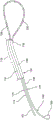
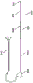
Fig. 1 is a perspective view of an ablation device and a lacing device according to an embodiment.
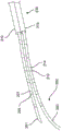
Fig. 2 is a perspective view of an ablation device and a lacing device, including a portion of the ablation device protruding from the lacing device, according to an embodiment.
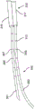
Fig. 3 is a perspective view of an ablation device and a lacing device, including a portion of the ablation device protruding from the lacing device, according to an embodiment.
Fig. 4 is a perspective view of an ablation device and a lacing device, including a portion of the ablation device protruding from the lacing device, according to an embodiment.
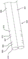
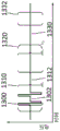
FIG. 5 is a perspective view of a binding device including a set of fiducial points on a portion of a clamping device according to an embodiment.
Fig. 6A is a side view of an ablation device in accordance with an embodiment. Fig. 6B is a perspective view of a distal portion of the ablation device of fig. 6A. Fig. 6C is a perspective view of the distal tip of the ablation device of fig. 6A.
Fig. 7A is a side view of an ablation device including a set of electrodes in accordance with an embodiment. Fig. 7B is a side view of the set of electrodes of fig. 7A with leads coupled thereto and disposed in an ablation device.
FIG. 8 is a block diagram of an electroporation system according to an embodiment.
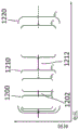
Fig. 9A is a side view of a binding device according to an embodiment. Fig. 9B is a schematic cross-sectional side view of the cinching device of fig. 9A. Fig. 9C is a schematic side view of the distal end of the cinching device of fig. 9A. Fig. 9D is a schematic side view of the distal tip of the cinching device of fig. 9A.
Fig. 10 is an example waveform including a voltage pulse train having a pulse width defined for each pulse, according to an embodiment.
Fig. 11 schematically illustrates a pulse hierarchy comprising pulse width, spacing between pulses, and grouping of pulses (grouping) according to an embodiment.
Fig. 12 provides a schematic illustration of nesting levels of monophasic pulses showing different levels of nesting levels, according to embodiments.
Fig. 13 is a schematic illustration of nesting levels of biphasic pulses showing different levels of nesting levels, according to an embodiment.
Fig. 14 is a perspective view of an ablation device according to an embodiment, wherein the ablation device includes a plurality of electrodes disposed along a shaft thereof and wrapped around a portion of a pulmonary vein and positioned within an epicardial space of the heart within the subject such that the ablation device forms an approximately closed profile around the pulmonary vein.
Fig. 15 is a perspective view of an ablation device and a lacing device, including portions of the ablation device protruding from each end of the lacing device, according to an embodiment.
Fig. 16 illustrates a method for positioning an ablation catheter relative to tissue of a patient, in accordance with an embodiment.
Fig. 17 illustrates a method for verifying ablation catheter positioning in accordance with an embodiment.
Detailed Description
Systems, devices, and methods for selectively and rapidly applying a pulsed electric field to ablate tissue by irreversible electroporation are described herein. The systems, devices, and methods described herein may generally be used to generate large electric field magnitudes at desired regions of interest and to reduce peak electric field values elsewhere to reduce unintended tissue damage. The devices described herein comprise flexible catheters that may be placed for pulsed electric field ablation of cardiac tissue. In some embodiments, the ablation device may be placed in the pericardial space through a subxiphoid approach or through direct surgical placement. Proper physical placement and applied tension between the ablation device (e.g., ablation catheter) and the tissue to be ablated can ensure targeted and efficient electroporation while reducing side effects and user error. For example, the cinching device and fiducial points disposed thereon may be used to aid in positioning and verification of the positioning of the ablation device relative to the target tissue.
The irreversible electroporation system as described herein can include a signal generator and a processor configured to apply one or more voltage pulse waveforms to a selected set of electrodes of an ablation device to deliver energy to a region of interest (e.g., for ablation energy in pulmonary vein ostial tissue) and in one embodiment provide a highly configurable set of electrode channels (e.g., allowing independent and arbitrary electrode selection). In some embodiments, the electrode pairing (e.g., anode-cathode subset) may be automatically configured based on the activated electrodes, although the electrodes to be activated and/or the electrodes for non-activation may be selected. The pulse waveforms disclosed herein may aid in the therapeutic treatment of various arrhythmias (e.g., atrial fibrillation). To deliver the pulse waveform generated by the signal generator, one or more electrodes of the ablation device may have insulated electrical leads configured to maintain a voltage potential of at least about 700V without dielectric breakdown of their corresponding insulation. The electrode subsets may be individually addressable such that the subsets may be controlled (e.g., deliver energy) independently of any other electrode of the device. In this way, the electrodes and/or electrode subsets may cooperatively deliver different energy waveforms at different timings for electroporation of tissue.
As used herein, the term "electroporation" refers to the application of an electric field to a cell membrane to alter the permeability of the cell membrane to the extracellular environment. As used herein, the term "reversible electroporation" refers to the application of an electric field to a cell membrane to temporarily alter the permeability of the cell membrane to the extracellular environment. For example, cells undergoing reversible electroporation may observe the temporary and/or intermittent formation of one or more pores in their cell membrane that close upon removal of the electric field. As used herein, the term "irreversible electroporation" refers to the application of an electric field to a cell membrane to permanently alter the permeability of the cell membrane to the extracellular environment. For example, cells undergoing irreversible electroporation can observe the formation of one or more pores in their cell membrane that remain after removal of the electric field.
The pulse waveforms for electroporation energy delivery as disclosed herein may enhance the safety, efficiency, and effectiveness of delivering energy to tissue by reducing the electric field threshold associated with irreversible electroporation, thereby producing more effective ablation lesions with reduced total energy delivered. In some embodiments, the voltage pulse waveforms disclosed herein may be hierarchical and have a nested structure. For example, the pulse shape may comprise a hierarchical grouping of pulses having an associated time scale. In some embodiments, the methods, systems, and devices disclosed herein may include one or more of the methods, systems, and devices described in international application serial number PCT/US2016/057664, filed on day 2016, 10, 19, and entitled "system, device, and method for delivering ablative energy to tissue (SYSTEMS, APPARATUSES AND METHODS FOR DELIVERY OF ABLATIVE ENERGY TO TISSUE)", and in U.S. provisional patent application No. 62/733,968, filed on day 9, 20, 2018, and entitled "system, device, and method for delivering ablative energy to tissue (SYSTEMS, APPARATUSES AND METHODS FOR DELIVERY OF ABLATIVE ENERGY TO TISSUE)", the contents of which are hereby incorporated by reference in their entirety.
In some embodiments, the system may further comprise a cardiac stimulator for synchronizing the generation of the pulse waveform to the paced heartbeat. The cardiac stimulator may electrically pace the heart with the cardiac stimulator and ensure pacing capture to establish periodicity and predictability of the cardiac cycle. A time window within the refractory period of the periodic cardiac cycle may be selected for voltage pulse waveform delivery. Thus, the voltage pulse waveform may be delivered during the refractory period of the cardiac cycle to avoid disruption of the sinus rhythm of the heart. In some embodiments, the system may optionally include one or more return electrodes. In some embodiments, the cardiac stimulator functionality may be integrated into a signal generator (e.g., ablation console, waveform generator console).
Typically, one or more catheters are advanced to the target site for ablating tissue. In cardiac applications, the electrodes through which the voltage pulse waveforms are delivered may be placed on an epicardial device. The methods described herein may include introducing an ablation catheter through a first lumen of a lacing device. The ablation catheter may be pushed out of the first lumen and looped around heart tissue, such as a set of pulmonary veins. The distal end of the ablation catheter may be advanced back into the cinching device through the distal end of the second lumen. The ablation catheter may then be pushed out from the proximal end of the cinching device such that the proximal and distal ends of the ablation catheter are proximal of the ablation catheter. The ends of the ablation catheter may be pulled away from the cinching device held in place so that the loop of the ablation catheter tightens around the tissue to increase contact and apply a predetermined force. A set of fiducial points disposed on the ablation catheter and/or the tightening device may be used to verify the orientation of the ablation catheter relative to the tightening device. For example, one or more electrodes and/or one or more electrode subsets may be disposed within a lumen of a lacing device. The electrodes may be inactive for ablation.
A pulse waveform may be generated and delivered to one or more identified electrodes (e.g., electrodes not covered by a lacing device) of an ablation catheter to ablate tissue. In some embodiments, the pulse waveform may be generated in synchronization with the pacing signal of the heart to avoid sinus rhythm disruption of the heart. In some embodiments, the electrodes may be configured as anode-cathode subsets. The pulse waveform may contain a stepped waveform to aid tissue ablation and reduce damage to healthy tissue.
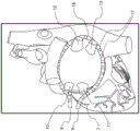
The systems and devices described herein generally include one or more catheters configured to ablate tissue in the left atrial chamber of the heart. As shown in fig. 14, in some embodiments, a pulmonary vein isolation (PV isolation) system may include an ablation device (15) (e.g., an ablation catheter) having a proximal portion (9) and a distal portion (8). The ablation device (15) may comprise a set of electrodes (17) disposed along its length, and wherein the ablation device (15) is wrapped in the epicardial space around all four pulmonary veins (10, 11, 12, 13) of the heart (7) of the subject or patient anatomy, wherein a proximal portion (9) and a distal portion (8) of the ablation device (15) respectively extend out and away to finally emerge from the chest of the patient. The ablation device (15) and any of the ablation devices described herein may be similar to the ablation catheter described in the following: PCT publication No. WO2014/025394, entitled "Catheters, catheter Systems and methods for piercing through tissue structures (Catheters, catheter Systems, and Methods for Puncturing Through a Tissue Structure)" filed on day 14 of 3 of 2013, as international application serial No. PCT/US2013/031252 (' 394PCT application publication), which disclosure is incorporated herein by reference in its entirety. The ablation device (15) may be positioned around the pulmonary veins (10, 11, 12, 13) using any suitable procedure and apparatus. For example, in some embodiments, an ablation device may be positioned around a pulmonary vein (10, 11, 12, 13) and/or heart (7) using a piercing apparatus positioned through a subxiphoid pericardial access location and using a guidewire-based delivery method, as described in the' 394PCT application publication filed on 15 th 6 of 2017 and/or in international application serial No. PCT/US2017/037609, which are incorporated herein by reference in their entirety. In some embodiments, a delivery catheter with a magnetic member configured to form a magnetic coupling across the pericardium fold as described in the' 394PCT application publication may be used to deliver a guidewire to a location around the heart. Similar and/or alternative methods may be used to deliver and position the ablation device (15). Alternative placement methods include direct surgical placement in an open chest as during a surgical procedure. In some embodiments, after the ends (8) and (9) of the ablation device (15) extend from the patient's chest and emerge, they may be cinched together using a cinching device, as described in more detail herein, to effectively hold the ablation device in place or stable orientation relative to each other.
In some embodiments, the ablation device (15) may be inserted into one end of the proximal end of a first lumen of a dual-tube lacing device, then pulled through the lumen, placed around the base of one or more pulmonary veins to form a loop around the pulmonary veins, and then inserted into the distal end of a second lumen of the lacing device, such that the distal end of the ablation device (15) extends from the proximal end of the second lumen of the lacing device, as described in detail herein.
Although fig. 14 illustrates a single catheter system, the embodiments described herein may also be applied to a dual catheter system surrounding the pulmonary veins, as described in international application No. PCT/US2015/031086 entitled "method and apparatus for multi-catheter tissue ablation (METHODS AND APPARATUS FOR MULTI-CATHETER TISSUE ABLATION)" filed on month 15 of 2015, which is incorporated herein by reference in its entirety.
A voltage (e.g., a DC voltage) for electroporation may be applied to a subset of electrodes identified as anodes and cathodes respectively located on two devices on approximately opposite sides of a closed profile defined by the shape of an ablation device (15) surrounding the pulmonary vein. The voltage may be applied in a brief pulse sufficient to cause irreversible electroporation, and may be in the range of 0.5kV to 10kV and more preferably in the range of 1kV to 2.5kV, so that a threshold electric field value of about 200 v/cm may be effectively achieved in the cardiac tissue to be ablated. In some embodiments, active electrodes on both devices may be identified automatically and/or manually on X-ray or fluoroscopic images obtained at appropriate angulation that allows identification of the geometric distance between the anode electrode and the cathode electrode or their respective centroids. For example, fiducial points (not shown in fig. 14 and described in more detail herein) may be disposed on a surface of one or more of the ablation device (15) and the tightening device and may be configured to be visualized by fluoroscopy to help identify the position of the electrode relative to the tightening device. Thus, the orientation of the ablation device (15) relative to the lacing device can be verified. In some embodiments, the signal generator may be configured to deliver a voltage only to a subset of electrodes not covered by the cinching device to deliver ablation energy to tissue.
In some embodiments, the voltage generator settings for irreversible electroporation may be automatically identified by the electroporation system based on this distance metric corresponding to the electrode location. In some embodiments, the voltage value may be selected by the user directly from a suitable dial, slider, touch screen, or any other user interface. The voltage pulse may cause an electrical current to flow between the anodic electrode and the cathodic electrode on opposite sides of a contour defined by the combined shape of the two devices, wherein the electrical current flows through the heart wall tissue and through the intervening blood in the heart chamber, wherein the electrical current enters the heart tissue from the anodic electrode and returns through the cathodic electrode. The forward and return current paths (leads) may be disposed within different devices and/or the same device, respectively. In some embodiments, all active electrodes on a given device may have similar polarity. Alternatively, in other embodiments, the electrodes on a single device may be activated as an anode-cathode set. During the application of the voltage pulse, a region of heart wall tissue in which the electric field is large enough for irreversible electroporation may be ablated.
In some embodiments, the pulse waveform may be generated in synchronization with the pacing signal of the heart to avoid sinus rhythm disruption of the heart. In some embodiments, the electrodes may be configured as anode-cathode (e.g., bipolar) subsets. The pulse waveform may contain a stepped waveform to aid tissue ablation and reduce damage to healthy tissue, as described in international application serial number PCT/US2016/057664, which is incorporated by reference herein.
As used herein, the term "electroporation" refers to the application of an electric field to a cell membrane to alter the permeability of the cell membrane to the extracellular environment. As used herein, the term "reversible electroporation" refers to the application of an electric field to a cell membrane to temporarily alter the permeability of the cell membrane to the extracellular environment. For example, cells undergoing reversible electroporation may observe the temporary and/or intermittent formation of one or more pores in their cell membrane that close upon removal of the electric field. As used herein, the term "irreversible electroporation" refers to the application of an electric field to a cell membrane to permanently alter the permeability of the cell membrane to the extracellular environment. For example, cells undergoing irreversible electroporation can observe the formation of one or more pores in their cell membrane that remain after removal of the electric field.
The pulse waveforms for electroporation energy delivery as disclosed herein may enhance the safety, efficiency, and effectiveness of delivering energy to tissue by reducing the electric field threshold associated with irreversible electroporation, thereby producing more effective ablation lesions with reduced total energy delivered.
The methods described herein may comprise placing tissue (e.g., pulmonary veins) in contact with an electrode. A pulse waveform may be generated and delivered to one or more electrodes of the device to ablate tissue. In some embodiments, the pulse waveform may be generated in synchronization with the pacing signal of the heart to avoid sinus rhythm disruption of the heart. In some embodiments, the electrodes may be configured as anode-cathode (e.g., bipolar) subsets. The pulse waveform may contain a stepped waveform to aid tissue ablation and reduce damage to healthy tissue.
I. System and method for controlling a system
SUMMARY
Disclosed herein are systems and devices configured for tissue ablation that facilitate tissue ablation by selectively and rapidly applying voltage pulse waveforms to achieve irreversible electroporation. In general, the systems described herein for ablating tissue may include a signal generator and an ablation device having one or more electrodes for selectively and rapidly applying a DC voltage to drive electroporation. As described in more detail herein, the systems and devices described herein include one or more ablation devices configured to ablate tissue of the heart. A voltage may be applied to a selected subset of electrodes, with anode electrode selection and cathode electrode selection having independent subset selections. The ablation device may be coupled to one or more electrode channels of the signal generator. Each electrode channel or subset of electrode channels may be configured independently as an anode or cathode, and the voltage pulse waveforms may be delivered in a predetermined sequence through one or more of the electrode channels. A pacing signal for cardiac stimulation may be generated and used to generate a pulse waveform by a signal generator in synchronization with the pacing signal.
Fig. 8 schematically illustrates an ablation system (800) configured to deliver a voltage pulse waveform for tissue ablation. The system (800) may include a signal generator (810) and an ablation device (840). The signal generator (810) may be coupled to at least one ablation device (840) having a set of one or more electrodes (842 a,842b, …,842 n).
Signal generator
The signal generator (810) may be configured to generate a pulse waveform for irreversible electroporation of tissue, such as cardiac tissue. The signal generator (810) may be a voltage pulse waveform generator and delivers pulse waveforms to a set of electrodes (842 a,842b, …,842 n) of the ablation device (840). The signal generator (810) may generate and deliver several types of signals, including, but not limited to, radio Frequency (RF), direct Current (DC) pulses (e.g., high voltage ultrashort pulses used in electroporation), stimulation range pulses, and/or mixed electrical pulses. For example, the signal generator (810) may generate monophasic (DC) pulses or biphasic (DC and AC) pulses. The signal generator (810) may include a processor (820), a memory (822), a set of electrode channels (82a, 824b, …,824 n), an energy source (826), a sensing circuit (828), a routing console (830), and a user interface (832). One or more signal generator components may be coupled using a communication bus. The processor (820) may incorporate data received from one or more of the memory (822), electrode channels (822 a, 254 b, …,824 n), energy source (826), sensing circuitry (828), routing console (830), user interface (832), ablation device (840) to determine parameters (e.g., amplitude, width, duty cycle, timing, etc.) of the voltage pulse waveform to be generated by the signal generator (810). The memory (822) may further store instructions for causing the processor (820) to execute modules, processes, and/or functions associated with the system (800), such as pulse shape generation and delivery and/or electrode channel configuration. For example, the memory (822) may be configured to store anode/cathode configuration data, electrode channel configuration data, pulse waveform data, fault data, energy discharge data, cardiac pacing data, patient data, clinical data, program data, sensor data, temperature data, and the like.
In some embodiments, an ablation device (840) (similar to any of the devices shown in fig. 1-4, 6, 7, 14, and 15) may include a device configured to receive and/or deliver the pulse waveforms described herein. For example, an ablation device (840) may be introduced around the pulmonary veins and positioned to align one or more electrodes (842 a,842b, …,842 n) with cardiac tissue and then deliver a pulse waveform to ablate the tissue. The ablation device (840) may include one or more electrodes (842 a,842b, …,842 n), which in some embodiments may be a set of individually addressable electrodes. For example, the electrodes (842 a,842b, …,842 n) may be grouped into one or more anode-cathode subgroups, such as a subgroup comprising one anode and one cathode, a subgroup comprising two anodes and two cathodes, a subgroup comprising two anodes and one cathode, a subgroup comprising one anode and two cathodes, a subgroup comprising three anodes and one cathode, a subgroup comprising three anodes and two cathodes, etc. The set of electrodes (842 a,842b, …,842 n) may comprise any number of electrodes, for example, 2, 3, 4, 5, 6, 7, 8, 9, 10, 12 or more electrodes. In some embodiments, predetermined subsets of electrodes may be electrically connected together with wires such that each such subset is individually addressable. In some embodiments, the methods, systems, and devices disclosed herein may comprise one or more of the methods, systems, and devices described in the following: U.S. patent application Ser. No. 15/499,804, filed on 27 of 2017, 4, and entitled "System, apparatus, and method for Signal Generation (SYSTEMS, DEVICES, AND METHODS FOR SIGNAL GENERATION)"; international application serial number PCT/US17/12099 filed on month 1 and 4 of 2017 and entitled "system, apparatus, and method for delivering pulsed electric field ablation energy to endocardial tissue (SYSTEMS, DEVICES, AND METHODS FOR DELIVERY OF PULSED ELECTRIC FIELD ABLATIVE ENERGY TO ENDOCARDIAL TISSUE)"; international application serial number PCT/US2013/031252 filed on 14 3/2013 and titled "catheter, catheter system and method for piercing through tissue structures and ablating tissue regions (CATHETERS, CATHETER SYSTEMS, AND METHODS FOR PUNCTURING THROUGH A TISSUE STRUCTURE AND ABLATING A TISSUE REGION)"; international application serial number PCT/US2018/029552 filed on month 4, 26 of 2018 and entitled "system, apparatus, and method for signal generation (SYSTEMS, DEVICES, AND METHODS FOR SIGNAL GENERATION)"; and international application serial number PCT/US2019/014226 filed on month 1, 18 of 2019 and entitled "system, device and method for focal ablation (SYSTEMS, DEVICES, AND METHODS FOR FOCAL ABLATION)", the contents of each of which are hereby incorporated by reference in their entirety.
In some embodiments, processor (820) may be any suitable processing device configured to execute and/or execute a set of instructions or code and may include one or more data processors, image processors, graphics processing units, physical processing units, digital signal processors, and/or central processing units. The processor (820) may be, for example, a general purpose processor, a Field Programmable Gate Array (FPGA), an Application Specific Integrated Circuit (ASIC), or the like. The processor (820) may be configured to run and/or execute application processes and/or other modules, processes, and/or functions associated with the system and/or a network (not shown) associated with the system. In some embodiments, the processor may include both a microcontroller unit and an FPGA unit, with the microcontroller sending electrode sequence instructions to the FPGA. Underlying device technologies may be provided in various component types, such as Metal Oxide Semiconductor Field Effect Transistor (MOSFET) technologies (e.g., complementary Metal Oxide Semiconductor (CMOS)), bipolar technologies (e.g., emitter-coupled logic (ECL)), polymer technologies (e.g., silicon conjugated polymer and metal conjugated polymer-metal structures), analog and digital hybrids, and the like.
In some embodiments, memory (822) may include a database (not shown) and may be, for example, random Access Memory (RAM), memory buffer, hard drive, erasable programmable read-only memory (EPROM), electrically erasable read-only memory (EEPROM), read-only memory (ROM), flash memory, or the like. The memory (822) may store instructions for causing the processor (820) to execute modules, processes, and/or functions associated with the system (800), such as pulse shape generation and/or electrode channel configuration.
In some embodiments, a set of electrode channels (254 a, 254 b, …,824 n) may contain a set of active solid state switches. The set of electrode channels (824 a, 254 b, …,824 n) may be configured in a variety of ways, including a separate anode/cathode configuration for each electrode channel. For example, the electrode channels (824 a,824b, …,824 n) may be grouped into one or more anode-cathode subgroups, such as a subgroup comprising one anode and one cathode, a subgroup comprising two anodes and two cathodes, a subgroup comprising two anodes and one cathode, a subgroup comprising one anode and two cathodes, a subgroup comprising three anodes and one cathode, a subgroup comprising three anodes and two cathodes, etc. The set of electrode channels (824 a, 254 b, …,824 n) may comprise any number of channels, for example 2, 3, 4, 5, 6, 7, 8, 9, 10, 12 or more electrode channels. The energy delivery may use any combination of electrode channels (254 a, 254 b, …,824 n) and any order for the energy delivery sequence. The energy delivered may be RF and/or any tissue ablation energy.
The set of electrode channels (824 a, 284 b, …,824 n) may be coupled to a routing console (830) to deliver energy to a set of electrodes (842) coupled to the routing console (830). The set of electrode channels (824 a, 284 b, …,824 n) may be coupled to an energy source (826) to receive energy (e.g., a pulse waveform). A processor (820) may be coupled to each electrode channel (824 a,824b, …,824 n) to configure an anode/cathode configuration for each electrode channel (824), which may be configured on a per pulse basis, per operator input, or the like. In some embodiments, each electrode channel (254 a, 254 b, …,824 n) may contain an electronic switch (e.g., bipolar transistor) and a drive circuit, as described in detail herein. In some embodiments, each electrode channel (254 a, 254 b, …,824 n) may have a bootstrap configuration for low and high frequency operation. For example, the pulse duration of the voltage pulse delivered through the electrode channel may range between about 1 microsecond and about 1000 microseconds. In biphasic mode, this corresponds to an approximate frequency range between about 500Hz and about 500KHz for frequencies associated with the voltage pulses.
In some embodiments, a controller including a processor (820) and a memory (822) may be coupled to each electrode in the set of electrodes (842). The controller may be configured to generate a pulse waveform and configure the set of electrodes (842) for pulse waveform delivery. A pulse waveform may be delivered to the set of electrodes (842).
In some embodiments, the energy source (826) may be configured to convert energy and supply the energy to a set of electrodes (842) coupled to the signal generator (810). The energy source (826) of the signal generator (810) may include a DC power source and be configured as an AC/DC switch. In some embodiments, the energy source (826) of the signal generator (810) may deliver rectangular wave pulses having peak maximum voltages up to about 7kV into devices having impedance ranges between about 30Ω and about 3000 Ω, including all values and subranges therebetween, at pulse widths in the range between about 1 microsecond and about 500 microseconds. In some of these embodiments, the energy source (826) may be configured to store energy. For example, the energy source (826) may include one or more capacitors to store energy from a power source. Although these examples are included for non-limiting illustration purposes only, it should be noted that various pulse waveforms having a series of pulse durations, intervals between pulses, pulse groupings, etc., may be generated depending on the clinical application.
In some embodiments, the sensing circuit (828) may be configured to determine an amount of current delivered to a device coupled to the signal generator (810) (e.g., an electrode (842) coupled to the electrode channel (824)). As described in more detail herein, the sensing circuit (828) may also be used to classify electrode channel faults, monitor capacitor discharge, and/or sense arcing. In some embodiments, the sensing circuit (828) may be a direct current sensing circuit and/or a low side sensing circuit. The sensing circuit may include one or more operational amplifiers, differential Amplifiers (DA), instrumentation Amplifiers (IA), and/or Current Shunt Monitors (CSM).
In some embodiments, the routing console (830) may be configured to electrically couple a set of electrodes (842) of the ablation device (840) to a set of electrode channels (254 a, 254 b, …,824 n). The routing console (830) may be configured to selectively deliver energy to the set of electrodes (842) using the set of electrode channels (824 a, 284 b, …,824 n). One or more ablation devices (840), each having a set of electrodes (842), may be coupled to the routing console (830). The set of electrodes (842) may include any number of electrodes, for example, 1, 2, 3, 4, 5, 6, 7, 8, 9, 10, 12, or more electrodes.
In some embodiments, electrode channels (824 a, 254 b, …,824 n) configured for energy delivery (e.g., configured as a pair of anode/cathode electrode channels) may not be adjacent to each other, but may be arbitrarily positioned along the ablation device (840).
The multi-electrode ablation device may allow for targeted and precise energy delivery to tissue. In some embodiments, the electrodes (842) of the ablation device (840) may be configured for energy delivery (e.g., as a pair of anode/cathode electrodes (842)) and may be disposed adjacent or at any other relative location along the ablation device (840). A signal generator (810) coupled to the ablation device (840) may include a set of electrode channels (254 a, 284 b, …, 824N) having N electrode channels corresponding to M electrodes (842N) of the ablation device (840). Each electrode channel (254 a, 254 b, …,824 n) of the signal generator (810) may be coupled to one of the electrodes (842) of the ablation device (840).
The configurable electrode channels and electrode selections may provide flexibility in positioning the electrodes for ablating a desired region of interest, as described in more detail herein. The routing console (830) may receive input from the processor (820) and/or the user interface (832) for electrode channel selection and energy delivery to one or more electrodes (842).
In some embodiments, the user interface (832) may be configured as a communication interface between an operator and the system (800). The user interface (832) may include input devices and output devices (e.g., a touch surface and a display). For example, patient data from the memory (822) may be received by the user interface (832) and visually and/or audibly output. Current data from the sensing circuit (828) may be received and output on a display of the user interface (832). As another example, an operator control having one or more buttons, knobs, dials, switches, trackballs, touch-surface, etc., input devices may generate control signals to the signal generator (810) and/or the ablation device (840).
In some embodiments, the input device of the user interface (832) may include a touch surface for operator input and may be configured to detect contact and movement on the touch surface using any of a variety of touch-sensitive technologies including capacitive, resistive, infrared, optical imaging, dispersive signal, acoustic pulse recognition, and surface acoustic wave technologies. Additionally or alternatively, the user interface (832) may include a step switch or foot pedal.
In some embodiments, the output device of the user interface (832) may include one or more of a display device and an audio device. The display device may include at least one of a Light Emitting Diode (LED), a Liquid Crystal Display (LCD), an electroluminescent display (ELD), a Plasma Display Panel (PDP), a Thin Film Transistor (TFT), and an Organic Light Emitting Diode (OLED). The audio device may audibly output patient data, sensor data, system data, other data, alarms, warnings, and the like. The audio device may comprise at least one of a speaker, a piezoelectric audio device, a magnetostrictive speaker, and/or a digital speaker. In one embodiment, the audio device may output an audible alert upon detection of a fault in the signal generator (810) and/or the ablation device (840).
In some embodiments, the signal generator (810) may be mounted on a cart or trolley. In some embodiments, the user interface (832) may be formed in the same or a different housing than the signal generator (810). The user interface (832) may be mounted to any suitable object, such as furniture (e.g., a bed rail), a wall, a ceiling, or may be free standing. In some embodiments, the input device may include a wired and/or wireless transmitter configured to transmit the control signal to a wired and/or wireless receiver of the signal generator (810).
In some embodiments, the systems described herein may include one or more sterile covers configured to create a sterile barrier around portions of the system (800). In some embodiments, the system (800) may include one or more sterile covers to form a sterile field. For example, a sterile cover may be placed between one or more ablation devices and the patient, forming a barrier between an inner non-sterile side containing the patient, signal generator, and ablation device, and an outer sterile side containing the operator. Additionally or alternatively, components of the system (800) may be sterilizable. The sterile drape may include, for example, a sterile drape configured to cover at least a portion of the system component. In one embodiment, a sterile cover (e.g., sterile drape) may be configured to create a sterile barrier with respect to a user interface (832) of the system (800). The sterile drape may be transparent and allow an operator to visualize and manually manipulate the user interface (832). The sterile cover may fit tightly around one or more system components or may be loosely covered to allow for adjustment of the components within the sterile field.
Ablation device and lacing device
The systems described herein may include one or more multi-electrode ablation devices (e.g., catheters) configured to ablate tissue for treating heart conditions and a tightening device configured to assist in positioning the ablation device relative to the tissue. In some embodiments, the ablation device may be configured to be positioned against tissue using a cinching device. The cinching device may include an elongate shaft defining a pair of parallel lumens. In some embodiments, the distal end of the elongate shaft may be curved to facilitate introduction of the ablation device into the pericardial space. In some embodiments, the lacing device may contain a set of fiducial points configured for visualization (e.g., imaged by fluoroscopy, X-rays). The ablation device and the cinching device may be configured for use in a cardiac procedure, such as creating a box-like lesion around a pulmonary vein in epicardial or pericardial space.
The ablation device may generally comprise a set of metal electrodes. The electrodes may also be generally atraumatic to reduce the risk of damage to the tissue from tearing and puncturing. For example, the edges of the electrodes may be rounded to reduce tissue damage and increase the uniformity of the electric field generated at the central and peripheral portions of the electrodes. To deliver the pulse waveform generated by the signal generator, one or more electrodes of the ablation device may have insulated electrical leads configured to maintain a voltage potential of at least about 700V without dielectric breakdown of their corresponding insulation. In some embodiments, the insulation on each of the electrical leads may maintain a potential difference of between about 200V and about 3,000V across its thickness without dielectric breakdown, including all values and subranges therebetween. The electrodes may be individually addressable such that each electrode may be controlled (e.g., deliver energy) independently of any other electrode of the ablation device. The electrodes may be connected, for example, to insulated electrical leads coupled to the signal generator to receive the pulse waveforms as described herein.
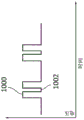
Fig. 1 is a perspective view of an ablation device (102) and a lacing device (130). The cinching device (130) may generally have a dual tube configuration sized to allow the ablation device to pass therethrough. For example, the ablation device (102) may be looped around a set of pulmonary veins (not shown in fig. 1) and through the cinching device (130) such that the proximal and distal ends of the ablation device (102) may be disposed outside the body and generally adjacent to each other. In other words, the end of the ablation device (102) may be positioned proximal to the cinching device (130). The cinching device (130) may then be manipulated to tighten the loop formed by the ablation device (102) around the pulmonary veins to aid in positioning the ablation device for tissue ablation. The ablation device (102) may include a handle (104) coupled to a proximal portion of the ablation device (102) and to a distal tip (101). The distal tip (101) may comprise an atraumatic shape to reduce trauma to tissue. The ablation device (102) may be configured to be slidably disposed within a first lumen (106) and a second lumen (131) of a lacing device (130). The first lumen (106) and the second lumen (131) may correspond to respective hollow tubular structures (e.g., first lacing catheter, second lacing catheter) that may be connected together along their length (L) to form a double tube or double lumen structure. The tightening device (130) can define a longitudinal axis.
In some embodiments, the ablation device (102) may include a series of fiducial points or marks at its proximal and distal ends. For example, a series of markers (112, 114) may be disposed on a distal portion of the ablation device (102) and a series of markers (144, 146) may be disposed on a proximal portion of the ablation device (102). As explained in further detail with reference to later figures, these series of markings may be used to determine an electrode (e.g., electrode (108)) disposed inside or outside of the cinching device (130), as described in further detail with reference to fig. 2-5. For example, the spacing between the marks (112, 114) may be set to correspond to the length of the electrode groups and/or the distance between the electrode groups. In some embodiments, the length (L) of the lacing device (130) may be a multiple of such length and/or distance to further facilitate determining a plurality or group of electrodes inside or outside the lacing device (130).
In some embodiments, the cinching device (130) may be sized and shaped for subxiphoid access. For example, the cinching device (130) may include a curved distal portion, as described herein with respect to fig. 9A-9D. The diameter of the ablation device (102) may be smaller than the diameter of the cinching device (130). In some embodiments, during use, the ablation device (102) may be introduced into the proximal end of the first lumen (106) of the cinching device (130). The ablation device (102) may extend from a distal end of the first lumen (106) and be configured to form a loop. For example, the ablation device (102) may include a central portion (124) having a high flexibility (e.g., a flexible curvature). An ablation device (102) may then be introduced into the distal end of the second lumen (131). The ablation device (102) may extend from the proximal end of the second lumen (131) such that the distal tip (101) of the ablation device (102) may be pushed out from the proximal end of the second lumen (131). The lacing device (130) may be sized to ensure that an appropriate number of electrodes (108) on the ablation device (102) may be drawn into or pulled into each lumen (106, 131) of the lacing device (130). Further, when the ablation device (102) is looped and advanced through the lacing device (130), a desired length of the ablation device (102) may extend from the proximal end of the lacing device (130) for manipulation. For example, the length of the cinching device (130) may range between about 6cm and about 30cm, including all values and subranges therebetween. The distal portion of the ablation device (e.g., distal to the electrode (108)) may range in length between about 20cm and about 70cm, including all values and subranges therebetween.
The ablation device (102) may include one or more electrodes (108) formed on a surface of the ablation device (102). In fig. 1, a set of electrodes (108) is disposed along a central portion (124) of the ablation device (102). In some embodiments, each electrode (108) may be individually addressable, while in other embodiments, one or more subsets of electrodes (108) may be electrically connected together with wires. For example, a group of three or four adjacent electrodes may be electrically connected together with wires as a subset of electrodes. In some embodiments, non-adjacent electrodes may be electrically connected together with wires. In some embodiments, the spacing between successive electrodes and/or electrode subsets may vary. Each electrode (108) may include or be attached to an insulated electrical lead configured to maintain a voltage potential of at least about 700V without dielectric breakdown of its corresponding insulation. In the case where more than one electrode is electrically wired together as an electrode group, a single such insulated lead may be connected to the electrode group. In some embodiments, the electrodes (108) may be approximately the same size, shape, and/or spacing. In some embodiments, the size, shape, and spacing of the electrodes (108) may vary.
The ablation device (102) may be configured to deliver a set of voltage pulse waveforms using a set of electrodes (108) to ablate tissue and electrically isolate one or more regions of the heart. At least a portion of the ablation device (102) may include a flexible curvature. For example, a central portion (124) of the ablation device (102) disposed between a proximal portion and a distal portion of the ablation device (102) may be flexible and configured to conform to a cardiac anatomy. The ablation device (102) may be configured to transition between a first configuration in which the ablation device (102) is partially advanced into the cinching device (130) and a second configuration in which a central portion (124) of the ablation device (102) forms a loop that may be configured to securely surround tissue, such as a pulmonary vein. In this way, the ablation device (102) and the tightening device (130) may increase contact with heart tissue.
In some of these embodiments, a handle (104) may be coupled to the ablation device (102) to form a hub from which cables and/or connectors (not shown) may be attached and which may be used to provide an access point for guidewire introduction. The connector may be connected to the signal generator directly or through an extension cable for delivering a voltage waveform for pulsed electric field ablation. In some embodiments, the handle (104) may include a guidewire lumen hub (not shown) for introducing a guidewire, which may provide mechanical support to the ablation device (102) when wrapped around tissue such as a pulmonary vein. In some embodiments, the handle may define an irrigation port configured to irrigate the guidewire lumen to aid in introducing the guidewire.
In some embodiments, a cinching device (130) may be positioned within the pericardial space at a location that allows access to the pulmonary veins for an ablation device (102), as described herein. The ablation device (102) may be advanced through the first lumen (106) and looped around a set of pulmonary veins (e.g., four pulmonary veins). For example, pericardial folds or pleats in the pericardium may be excised to allow the ablation device (102) to surround the veins at the base of the trunk of all four pulmonary veins. The ablation device (102) may be advanced through the second lumen (131). The cinching device (130) may be advanced toward the heart, angled obliquely relative to the chest of the patient, and placed on the posterior side of the heart. The proximal and distal ends of the ablation device (102) may be pulled through the cinching device (130) and away from the heart to apply a predetermined amount of force to the pulmonary veins using the annular center portion (124) of the ablation device (102).
The number of electrodes that may be drawn into the cinching device (130) when the ablation device (102) is cinched around the pulmonary vein may depend on the size of the left atrium and the amount of force applied. When the electrodes (108) are looped around and in contact with the pulmonary vein, no electrode (108) disposed within the lumen of the cinching device (130) should receive energy. An electrode (108) distal to the distal end of the cinching device (130) may be configured to receive ablation energy. Some embodiments described herein may provide a direct visual means to identify the position of a set of electrodes (108) of an ablation device (102) relative to a lacing device (130).
Fig. 6A is a side view of an example non-limiting ablation device (602). The ablation device (602) may include a catheter having a proximal portion (603), a central portion (624), and a distal portion (601). The proximal, distal, and central portions of the catheter may each be constructed of a compliant and/or flexible material to allow one or more portions of the ablation device (602) to readily adapt to the heart anatomy. The distal portion (601) may contain an atraumatic distal tip (605), as shown in fig. 6B and 6C. The central portion (624) may include a set of electrodes (608) disposed on a surface of the ablation device (602). The set of electrodes (608) may include a plurality of subgroups, wherein each subgroup has a first length. Each electrode subset may be spaced apart from an adjacent subset by a second length. The second length may be greater than the first length. Fig. 6A shows the set of electrodes grouped into a subset of three electrodes each. Each electrode within the subgroup may have a third length. In some embodiments, the length of one or more electrodes within a subset may be different. For example, fig. 7A and 7B described below provide a more detailed view of a subset of three electrodes having different lengths. Alternatively, the length of each electrode within a subset may be the same.
The handle (604) may be coupled to a proximal portion (603) of the ablation device (602). A set of leads (640) may be coupled to the handle (604) and may be disposed within a lumen of the ablation device (602) to connect to the set of electrodes (608).
Fig. 7A and 7B are side views of a set of electrodes (708) of an example ablation device (702). The set of electrodes (708) may be disposed on a central portion (724) of the ablation device (702). As described herein, one or more sets of electrodes (708) may not be used to deliver ablation energy, such as when those electrodes are disposed within the lumen of a lacing device. The electrode sub-groups (730, 740) may have a first length (750) and may be separated by a second length (720). In some embodiments, the electrodes may be formed from a platinum-iridium material. In some embodiments, the set of electrodes (708) may comprise a plurality of triplets (triplets) subgroups or groups, wherein the electrodes (each electrode in the form of a ring) may have a third length ranging between about 1mm and about 12mm, including all values and subranges therebetween. Each electrode within a subset or group (730, 740) of electrodes may be separated by a fourth length (710). In some embodiments, the number of electrode subsets may range between about 4 and about 20, including all values and subranges therebetween.
Fig. 9A is a side view of a cinching device (930). The lacing device may include a distal portion having a curved portion (920) and a distal tip (910). The curved portion (920) may aid in positioning and advancement of the ablation device within the body lumen. Fig. 9B is a cross-sectional side view of a cinching device (930) having a first lumen (940) and a second lumen (950). The diameters of the lumens (940, 950) may be the same. The diameter may be approximately the diameter of an ablation catheter (not depicted) or greater such that the lumen is designed for use with the ablation catheter. Fig. 9C and 9D are schematic side views of the distal end of a cinching device (930) that includes a curved portion 920 and a distal tip 910. In some embodiments, the cinching device (930) may be formed from Pebax (e.g., pebax 40D). In some embodiments, the distal tip (910) may be between about 5mm and about 25mm in length and may be constructed of a material that is visible under fluoroscopy. In some embodiments, one or more portions of the cinching device (930) (e.g., the entire surface of the cinching device (930)) may be visible under fluoroscopy. The distal tip (910) may be atraumatic to reduce trauma to the tissue. In some embodiments, the curvature of the curved portion (920) may be between about 30 degrees and 60 degrees. For example, the curvature of the curved portion (920) may be about 45 degrees.
Datum point
In some embodiments, one or more of the ablation device and the tightening device may include a set of fiducial points that allow a surgeon and/or imaging system to determine the position of a set of electrodes of the ablation device relative to the tightening device. For example, a set of indicia disposed on one or more of the proximal and distal portions of the ablation device may correspond to a number of electrodes or electrode subsets within (e.g., within) a lumen of the lacing device and/or a number of electrodes or electrode sets disposed outside of the lacing device. Thus, the electrode or subset of electrodes within the lacing device may be configured to deactivate, while the remaining electrode or set of electrodes extending or exposed outside the lacing device may be configured to deliver ablation energy to tissue, such as a portion of a set of pulmonary veins surrounding the heart. As used herein, a fiducial corresponds to a marking, symbol (e.g., number, letter), geometric shape, hole, recess, protrusion, texture, combinations thereof, etc., disposed along a length of one or more of the ablation device and the lacing device.
Fig. 2 is a perspective view of an ablation device (202) and a lacing device (230), wherein a proximal portion (203) of the ablation device (202) may extend through a proximal end of a first lumen (219) of the lacing device (230). The distal portion (201) of the ablation device (202) may extend through the proximal end of the second lumen (210) of the cinching device (230). The proximal portion (203) may include a first set of proximal reference points (212) and a second set of proximal reference points (214) disposed along its length on a surface thereof. The first set of proximal reference points (212) may be different (e.g., larger, wider) than the second set of proximal reference points (214). The fiducial points in the first set of proximal fiducial points (212) and the second set of proximal fiducial points (214) may be alternately disposed along a length of the ablation device (202). Adjacent fiducial points in the first set of proximal fiducial points (212) and the second set of proximal fiducial points (214) may be spaced apart by a length (not shown in fig. 2) of an electrode of the ablation device (202). Likewise, the distal portion (201) may include a first set of distal reference points (205) and a second set of distal reference points (207) disposed along its length on its surface. The first set of distal reference points (205) may be larger than the second set of distal reference points (207). The fiducial points in the first set of distal fiducial points (205) and the second set of distal fiducial points (207) may be alternately disposed along the length of the ablation device (202). Adjacent fiducial points in the first set of distal fiducial points (205) and the second set of distal fiducial points (207) may be spaced apart by a length of the electrode. In some embodiments, the first set of fiducial points (205, 212) and the second set of fiducial points (207, 214) may be identified and distinguished by number, location, length, thickness, width, depth, shape, color, orientation, texture, material, combinations thereof, and the like.
In some embodiments, each electrode subset of the ablation device (202) (e.g., a set of three adjacent electrodes electrically connected together with a wire) may have a first length, and the length of the cinching device (230) may be an integer multiple of the sum of the first length and the distance between successive electrode groups (second length). For example, if p represents the end-to-end length (first length) of the electrode subset and d represents the spacing distance (second length) between the electrode groups, the first set of fiducial points (e.g., larger marks) may be disposed at a third length r= (p+d) from the distal-most and/or proximal-most electrode and repeated periodically at this length interval r (on both the distal and proximal portions of the ablation device (202)). For example, a shorter mark may be adjacent to a larger mark with a spacing equal to the length of one electrode (e.g., the length of the smallest electrode in each electrode subset or the fifth length). The set of fiducial points disposed proximal to the tightening device (230) allows a surgeon to determine the number of electrodes disposed within the lumen of the tightening device (230) based on the number of sets of fiducial points disposed proximal to the tightening device (230) (e.g., by visual confirmation, tactile confirmation, etc.). For example, if three complete sets (e.g., large and small) of fiducial points disposed along the distal portion (201) of the ablation device (202) are visible proximal to the lacing device (230) such that a shorter marker of one set of fiducial points is positioned proximal to the lacing device (230), two electrode subsets may be disposed within the second lumen (210) (e.g., depending on the length of the second lumen (210)), and a majority of the electrodes in the third electrode subset may be disposed distal to the lacing device (230) and exposed for delivery of ablation energy. The number of electrode subunits disposed within the lumen of the cinching device (230) and the number of electrode subunits disposed distal to and exposed outside the lumen of the cinching device (230) may depend on, for example, the length of the lumen of the cinching device (230), the total number of electrode subunits, and the like.
For example, fig. 15 depicts a distal portion (1501) of the ablation device (1502) in a lumen (1503) (e.g., lumen, tube) of a cinching device (1530). For clarity, the adjacent lumen of the cinching device (1530) and the proximal portion of the ablation device (1502) are not shown. First and second sets of fiducial points (1505, 1507, 1511, 1513, 1515, 1517, 1519, 1520) with longer and shorter marks, respectively, are shown distributed along a distal portion (1501) of an ablation device (1502). When one pair of fiducial points (1505, 1507) is exposed and spaced from the proximal end of lumen (1503), the other three fiducial point pairs (1511, 1513), (1515, 1517) and (1519, 1520) are disposed inside lumen (1503).
The distal-most electrode subset of the ablation device (1502) may include electrode triplets (1525, 1526, 1527). As depicted in fig. 15, the distal (1522) and proximal (1523) ends of the distal-most electrode (1525) in the triplet are disposed within the lumen (1503) such that the electrodes (1526, 1527) are exposed and distal to the lumen (1503) and may be configured for ablative energy delivery.
In this embodiment, the length of lumen (1503) may be four times the spacing (e.g., the sum of the first length and the second length) between the distal ends of consecutive electrode triplets. As described above, this interval r is the sum of the length p (first length) of the electrode triplets and the gap d (second length) between adjacent electrode triplets. The spacing between successive pairs of fiducial points (e.g., the distance between a larger fiducial point (1511) and a larger fiducial point (1515)) may be configured to be equal to the distance r between the distal ends of successive electrode triplets. In this example, the length of the lumen may be an integer multiple of the distance r (i.e., the distance between the distal ends of consecutive fiducial points). Thus, the presence of a fiducial point (1505, 1507) exposed proximal to the lumen (1503) can visually confirm that a single electrode (in this example, the distal-most electrode (1525)) in the distal-most electrode triplet is disposed within the lumen (1503), while the remaining electrodes (1526, 1527) in the electrode triplet are exposed distal to the lumen (1503).
It should be appreciated from the above description that various other reference point configurations may enable other estimations. For example, in one embodiment, reference point sets may be used, where each reference point set is used to replicate, represent, and/or otherwise correspond to an electrode group (e.g., electrode triplets in the above examples). In some embodiments, the number of electrodes disposed within the lumen of the cinch device tube and which electrodes of the most distal, most exposed electrode group are disposed within the lumen of the cinch device may be visually confirmed, as a corresponding number of fiducial groups will be visible on the distal portion of the ablation proximal to the cinch device.
As another example, in another embodiment, the single fiducial points may be continuously spaced apart by a length (e.g., distance r) corresponding to the distance between the distal ends of successive electrode groups. The number of fiducial points visible on the distal portion of the ablation device outside of the lacing device may correspond to the number of electrode groups disposed within the lumen of the lacing device.
While electrode groups (e.g., electrode sub-groups) in the form of electrode triplets are shown and described with respect to fig. 15, it should be apparent to those skilled in the art that other electrode groupings may be implemented. For example, electrode groups may be wired together in subsets of electrode diads, quads, etc., without limitation, and the methods and embodiments provided herein as examples may be altered in detail without departing from the scope of the invention. In some embodiments, the length of each electrode within a group may be the same (e.g., as depicted in fig. 15), while in other embodiments, the length of the electrodes within a group may be different (e.g., as depicted in fig. 7A and 7B).
Fig. 3 is a perspective view of the ablation device (302) and the lacing device (330), wherein a proximal portion (303) of the ablation device (302) may extend through a proximal end of a first lumen (317) of the lacing device (330). The distal portion (301) of the ablation device (302) may extend through the proximal end of the second lumen (315) of the cinching device (330). The proximal portion (303) may include a set of proximal fiducial points (309, 313) (e.g., marks) disposed along its length on its surface. The distal portion (301) may include a set of distal fiducial points (305, 307) (e.g., markers) disposed along its length on its surface. In some embodiments, the proximal set of fiducial points and the distal set of fiducial points may be identified and distinguished by one or more characteristics including number, position, length, thickness, width, depth, spacing, shape, color, pattern, orientation, texture, material, combinations thereof, and the like.
In some embodiments, each electrode subset of the ablation device (302) (e.g., a set of three adjacent electrodes electrically connected together with a wire) may have the same length, and the length of the cinching device (330) may be an integer multiple of the sum of the electrode subset length and the distance between successive electrode groups. For example, if p represents the end-to-end length of the electrode subset and d represents the spacing distance between the electrode groups, the set of fiducial points may be disposed starting at a distance r= (p+d) from the most distal and/or proximal electrode and periodically repeated at this length interval r, for example, on both the distal and proximal portions of the ablation device (302).
The set of fiducial points disposed proximal to the tightening device (330) allows a surgeon to determine the number of electrodes disposed within the lumen of the tightening device (330) based on the number of fiducial points disposed proximal to the tightening device (330) determined based on visual confirmation, tactile confirmation, and/or other types of confirmation. For example, if four complete fiducial points disposed along the distal portion (301) of the ablation device (302) are visible outside of the lacing device (330), three electrode subgroups may be disposed within the second lumen (315) of the lacing device (330). Depending on whether more than half of the length p is visible between the indicium closest to the lacing device (330) and the proximal end of the lacing device (330), it may be determined that the fourth electrode group is inside the lacing device (330) or exposed outside the lacing device (330), respectively.
Furthermore, the number of electrode subgroups disposed within the first lumen (317) of the lacing device (330) may be determined using an exposure datum (e.g., visual, tactile, etc.) disposed along a length of a proximal portion (303) of the ablation device (302) proximal to the lacing device (302). For example, placement of the two electrode subsets within the first lumen (317) of the cinching device (330) may be determined based on a number of visible fiducial points along the proximal portion (303). Once the number of electrode subsets in the first lumen (317) and the second lumen (315) is determined, the signal generator may be configured to deliver energy to the electrodes looped around (and thus exposed by) the pulmonary veins, without delivering energy to the electrodes within the cinching device (330). For example, the user may input fiducial point information into a user interface of the signal generator.
Fig. 4 is a perspective view of an ablation device (402) and a lacing device (430), wherein a proximal portion (403) of the ablation device (402) may extend through a proximal end of a first lumen (417) of the lacing device (430). The ablation device (402) may be similar to other ablation devices described herein, but with fiducial points implemented as alternating deep and shallow bands. The distal portion (401) of the ablation device (402) may extend through the proximal end of the second lumen (415) of the cinching device (430). The proximal portion (403) may include a set of proximal fiducial points (409, 410) disposed along its length (e.g., alternating dark and light bands) on its surface. The distal portion (401) may include a set of distal fiducial points (405, 406) disposed along its length (e.g., alternating dark and light bands) on its surface. In some embodiments, the proximal set of fiducial points and the distal set of fiducial points may be identified and distinguished by number, location, length, thickness, spacing, width, depth, shape, color, pattern, orientation, texture, combinations thereof, and the like.
In some embodiments, each electrode subset of the ablation device (402) (e.g., a set of three adjacent electrodes electrically connected together with a wire) may have the same length, and the length of the cinching device may be an integer multiple of the sum of the electrode subset length and the distance between successive electrode groups. For example, if p represents the end-to-end length of the electrode sub-set and d represents the pitch distance between the electrode groups, the set of fiducial points may be disposed in the form of alternating bands of length r= (p+d) starting from the distal-most electrode edge on the distal portion and starting from the proximal-most electrode edge on the proximal portion of the ablation device, respectively.
The set of fiducial points disposed external to the tightening device (430) allows a surgeon to determine the number of electrodes disposed within the lumen of the tightening device (430) based on the number of fiducial points disposed external to the tightening device (430) that can be determined using visual, tactile, etc. confirmation. For example, if four complete sets of bands disposed along the distal portion (401) of the ablation device (402) are visible proximal to the cinching device (430), at least three electrode subsets may be disposed within the second lumen (415) of the cinching device (430). Depending on whether more than half of the length p is visible between the indicium closest to the tightening means (430) and the proximal end of the tightening means (430), it may be determined that the fourth electrode group is inside the tightening means (430) or exposed outside the tightening means (430), respectively.
Furthermore, a number of electrode subgroups disposed within the first lumen (417) of the cinching device (430) may be determined using a visible fiducial point disposed along a length of a proximal portion (403) of the ablating device (402) proximal of the cinching device (402). For example, placement of the two electrode subsets within the first lumen (417) of the cinching device (430) may be determined based on a number of visible fiducial points along the proximal portion (403). Once the number of electrode subsets in the first lumen (417) and the second lumen (415) is determined, the signal generator may be configured to deliver energy to the exposed electrodes looped around the pulmonary vein without delivering energy to the electrodes within the cinching device (430). For example, the user may input fiducial point information into a user interface of the signal generator.
Fig. 5 is a perspective view of a cinching device (530) that includes a first lumen (501) (e.g., proximal tube) and a second lumen (500) (e.g., distal tube). The first lumen (501) and the second lumen (500) may include a set of fiducial points (503, 505, 507, 512, 513) on their surfaces disposed along their lengths adjacent a proximal end (510) of the cinching device (530). In some embodiments, the set of fiducial points may be identified and distinguished by number, location, length, thickness, width, depth, shape, color, pattern, orientation, texture, material, combinations thereof, and the like.
In some embodiments, the distance from the proximal end (510) of the cinching device (530) to the first fiducial (503) may be equal to the length of a first electrode in a subset of electrodes (e.g., three electrodes) of the ablation device. In some embodiments, the distance from the first fiducial (503) to the second fiducial (505) may correspond to a distance or spacing between a first electrode and a second electrode in an electrode subset of three electrodes. In some embodiments, the distance between the second fiducial (505) and the third fiducial (507) may correspond to the length of the second electrode in the electrode subset of three electrodes. In some embodiments, the distance from the third fiducial (507) to the fourth fiducial (512) may correspond to a distance or spacing between the second electrode and the third electrode in the electrode subset of three electrodes. In some embodiments, the distance from the fourth datum (512) to the fifth datum (513) may be equal to the length of the third electrode in the electrode subset of three electrodes. In this illustrative example, the set of fiducial points on each lumen of the lacing device (530) may correspond to electrode triplets of the ablation device configured to extend through the lacing device (530).
In some embodiments, an ablation device and a lacing device, each having a fiducial point, may be used to improve the determination of the position of the electrode relative to each lumen of the lacing device. For example, the fiducial points may be used to determine portions of the electrode subset that are disposed external to the lacing device for each lumen of the lacing device. For example, such fiducial points on the binding device may be provided in combination with fiducial points on the ablation device in the form of alternating bands as illustrated in fig. 4 to aid in such determination of exposed portions of the electrode subset outside of the binding device. Once the number of electrode subsets in each lumen is determined, the signal generator may be configured to deliver energy to the electrodes looped around the pulmonary veins, without delivering energy to the electrodes within the lacing device. For example, the user may input fiducial point information into a user interface of the signal generator.
In some embodiments, using fiducial points on the ablation device and/or the lacing device verifies that the electrodes are properly deployed at the distal tip of the lacing device (i.e., for both the distal and proximal tubes or lumens of the lacing device, most of the electrodes in the electrode group are deployed just outside the distal tip of the lacing device), the orientation of the ablation device relative to the lacing device may be locked in place. In some embodiments, a locking mechanism may be used to hold the ablation device in place relative to the cinching device. For example, a clip (e.g., a surgical clip), surgical tape, a combination thereof, or the like at the proximal end of the tightening device may be used to hold the ablation device in place. In some embodiments, the locking mechanism may be engaged after a predetermined number of electrodes in the electrode group are disposed distally of the cinching device (e.g., a majority of the electrodes in the electrode subset are disposed outside of the distal ends of the first and second lumens of the cinching device).
In this way, the electrodes disposed in a loop along the ablation device may be securely positioned around a set of four pulmonary veins. Pulsed electric field ablation energy may be delivered to an appropriate electrode set or pair (e.g., exposed electrodes surrounding the ring) to rapidly ablate tissue surrounding the pulmonary vein (e.g., creating a box-like lesion). Such a method of delivering a box-like lesion may, for example, be useful as a therapeutic method for one or more arrhythmic conditions, such as atrial fibrillation.
Pulsed electric field voltage pulses having suitable voltage levels (e.g., in the kilovolt range) may be delivered in the form of suitable waveforms as described herein. The waveforms may have a hierarchical structure with multiple levels of hierarchy as appropriate for efficient and effective therapy delivery. As described in more detail herein, the signal generator may be configured to deliver a set of pulse waveforms to the ablation device. In some embodiments, initiation of ablation delivery may occur in synchronization with a set of pacing pulse timings (e.g., during a refractory period associated with the set of pacing pulses).
The electrode as described may be composed of any suitable biocompatible conductive material including, but not limited to, one or more of silver, palladium, stainless steel, platinum, titanium, platinum-iridium alloys, gold, copper, nickel, combinations thereof, and the like. In some embodiments, the electrode material may be electroplated, coated, and/or otherwise applied in a suitably thick layer on top of the different substrate materials. In some embodiments, the electrode portions may be coupled using annealing, welding, fusing, crimping, laminating, combinations thereof, and the like. The splines, rings, and body of the disclosed ablation devices may be constructed of any suitable biocompatible material, including metals, glasses, ceramics, polymers, combinations thereof, and the like. The catheter shaft may be made of a flexible polymeric material such as teflon, nylon, pebax, combinations thereof, and the like.
In the embodiments described above, but not by way of limitation, the ablation device itself may be a steerable device having pull wires for controlling deflection by a suitable mechanism in the catheter handle, as known to those skilled in the art.
II method
Also described herein are methods for ablating tissue (e.g., cardiac tissue) using the systems and devices described above. An ablation device may be introduced into the epicardial space. The ablation catheter may be advanced through a cinching device and looped around heart tissue, such as a set of pulmonary veins. The distal end of the ablation catheter may be advanced back through the cinching device such that the end of the ablation catheter may be pulled away from the cinching device, thereby causing the loop of the ablation catheter to tighten around the tissue to increase contact and apply a predetermined force. In some embodiments, a set of fiducial points disposed on the ablation catheter and/or the lacing device may be used to verify the orientation of the ablation catheter relative to the lacing device. The energy delivery to a set of electrodes of the ablation catheter may be based on the electrodes identified using fiducial points. For example, a pulse waveform may be generated and delivered to one or more identified electrodes of the ablation catheter (e.g., electrodes exposed outside of the lacing device) to ablate tissue.
The methods described herein generally involve introducing an ablation device and positioning it through a cinching device and looping around one or more pulmonary veins. Once the proximal and distal ends of the ablation device are positioned proximal to the cinching device, the cinching device may be positioned and the end of the ablation device may be pulled through the cinching device such that the loop formed by the ablation device tightens around a set of pulmonary veins to perform the ablation. The orientation of the ablation device relative to the cinching device may be locked in place. The pulse waveform may be delivered by one or more electrodes of an ablation device to ablate tissue. In some embodiments, the pulse waveform may include a set of levels of hierarchy to reduce total energy delivery. It should be appreciated that any of the ablation devices described herein may be used to ablate tissue using the methods discussed below as appropriate.
As a non-limiting example, in some embodiments, the system may include one or more ablation devices (e.g., as shown and described with respect to fig. 1-7, 14, and 15) that may be used to ablate tissue. Fig. 16 is a flow chart (1600) of an example method of a tissue ablation process. At 1604, a distal end of the first device can be advanced into a proximal end of a first lumen of a second device (e.g., a cinching device). The first device (e.g., an ablation device, such as ablation device (102)) may be any of the ablation devices (15, 102, 202, 302, 402, 602, 702, 840, 1501) described herein. At 1606, the first device can be advanced through the first lumen of the cinch device and pushed out of the distal end of the first lumen. At (1608), the first device may be looped around tissue of the patient. For example, the ablation device may extend from the distal end of the cinching device and loop around tissue, such as a set of four pulmonary veins, at the base of the trunk of the vein. In some embodiments, pericardial folds or pleats in the pericardium may be excised to allow for such looping.
At 1610, the first device may be advanced back into the first device through the proximal end of the second lumen. A portion of the first device may be disposed in a first lumen while a more distal portion of the first device is disposed and/or advanced into a second lumen of the second device. At (1612), the first device may be advanced through a second lumen of the cinching device and pushed out of a proximal end of the second lumen. The proximal and distal ends of the ablation device may extend from the proximal end of the cinching device. The cinching device may be angled obliquely relative to the patient's chest. At (1614), the proximal and distal ends of the first device may be pushed away from the proximal end of the second device. For example, the proximal and distal ends of the ablation device are pulled through the cinching device until the loops of the ablation device contact and securely surround all of the pulmonary veins. In this way, the loop formed by the central portion of the ablation device may be bent around the pulmonary vein (e.g., forming a lasso). Alternatively, the ablation device may be looped first around a set of four pulmonary veins, and then the proximal and distal ends of the ablation device may be advanced through both lumens of the cinching device. For example, after the ablation device is looped around the tissue, a lacing device may be advanced over the ablation device in a distal direction toward the heart. The user may drag the ablation device away from the predetermined amount to increase contact between the ablation device and the tissue and/or apply a predetermined amount of force from the ablation device to the tissue. Depending on the size of the left atrium, one or more of the electrodes of the ablation device may be drawn into the cinching device as the ring is tightened around the pulmonary vein. The electrodes exposed on the ring may be used to deliver ablation energy to tissue.
In some embodiments, the guidewire may be positioned around cardiac tissue (e.g., one or more pulmonary veins of the heart) using procedures and methods as described in the' 394PCT application publication prior to advancing the distal end of the first device into the proximal end of the first lumen of the second device at 1604. The end of the guidewire may be placed within a second device (e.g., a cinching device), and then a first device (e.g., an ablation device) may be delivered over the guidewire such that, at 1604, a distal end of the first device is advanced through a proximal end of a first lumen of the second device. In some embodiments, before advancing the first device through the second device at 1604, the distal end of the second device may be advanced into the open pericardial space of the patient at a location that allows access to the rear of the left atrium. Alternatively, once the first device has been advanced through the first lumen and the second lumen of the second device, the distal end of the second device may be advanced into the open pericardial space at (1614). Although the distal end of the second device may be advanced into the pericardial space, the proximal end of the second device may remain external to the heart and/or patient.
In some embodiments, the guidewire may be advanced through a first device (e.g., an ablation device) such that the first device and the guidewire may be advanced together through a first lumen of a second device (e.g., a cinching device) so as to encompass the pulmonary vein and the left atrial back wall and then pulled back through a second lumen of the second device. Placement of the first device and/or the second device may be through any of a subxiphoid approach, an open chest procedure, and a direct open chest approach.
In some embodiments, the process may proceed from (1614) to the flowchart (1700) of fig. 17, described in greater detail herein, wherein a user (e.g., a surgeon) may observe one or more sets of fiducial points on one or more of the ablation device and the lacing device to determine the position of the electrodes relative to the lacing device (e.g., the number of electrodes within the first lumen and the second lumen of the lacing device). In some embodiments, at (1618), the orientation of the first device may be locked relative to the second device. For example, a locking member such as a clip may be used to hold the lacing device in a fixed orientation relative to the ablation device such that a user holding one of the lacing device and the ablation device may hold the other device in a relatively fixed orientation. The user may verify the positioning of the first device relative to the tissue. For example, a user may identify and select an electrode of a first device to receive ablation energy and conversely inhibit energy delivery to an electrode covered by a second device. At (1620), a pulse waveform may be delivered to tissue through a set of electrodes of a first device.
In some embodiments, the set of electrodes may be configured as a set of anode-cathode pairs. In some embodiments, the electrodes or appropriate sequences of pairs of anode-cathode subsets of electrodes may be electrically activated in a sequential manner to deliver a pulse waveform with each anode-cathode pair. For example, the set of electrodes may be activated sequentially in a clockwise or counter-clockwise manner. As another example, the cathode electrodes may be sequentially activated along with corresponding sequential anode electrode activation until ablation is complete. The electrodes may be activated all at once or in a predetermined sequence. The sequential activation pattern may occur over the entire set of paired anode-cathode sub-sets during a single heartbeat or over a portion of the set of paired anode-cathode sub-sets during a single heartbeat. Such activation for ablation delivery can typically occur over multiple heartbeats.
In some embodiments, the electrodes may be individually addressable, and the electrodes may be energized in any order using any pulse waveform sufficient to ablate tissue by irreversible electroporation. In some embodiments, ablation may be delivered rapidly with all electrodes activated simultaneously. Various such electrode pairing options exist and may be implemented based on their convenience. In some embodiments, a hierarchical voltage pulse waveform having a nested structure and time interval hierarchy as described herein may be useful for irreversible electroporation, providing control and selectivity among different tissue types. The pulse waveform may be generated by a signal generator (e.g., signal generator 810) and may contain a set of levels in a hierarchy. As disclosed herein, various stepped waveforms may be generated with a signal generator. For example, the pulse waveform may include a first stage of a hierarchy of pulse waveforms, the first stage including a first set of pulses. Each pulse has a pulse duration and a first time interval separating successive pulses. The second stage of the hierarchy of pulse waveforms may comprise a plurality of the first set of pulses as the second set of pulses. The second time interval may separate consecutive first sets of pulses. The second time interval may be at least three times the duration of the first time interval. The third level of the hierarchy of pulse waveforms may comprise a plurality of the second set of pulses as the third set of pulses. The third time interval may separate consecutive pulses of the second set. The third time interval may be at least thirty times the duration of the second time interval.
It should be appreciated that while the examples herein identify separate monophasic and biphasic waveforms, it should be appreciated that a combined waveform may also be generated in which some portions of the waveform hierarchy are monophasic and other portions are biphasic. Voltage pulse waveforms having a hierarchical structure (optionally with a certain time delay) may be applied across different anode-cathode subgroups. The generated pulse waveform may be delivered to tissue. Thus, in some embodiments, a continuous transmural region of ablated tissue may electrically isolate the pulmonary vein from the body of the left atrium.
In some embodiments, a portion of the electrode subset may be distal to the lacing device. In order to deliver ablation energy with the electrode subsets wired together, it may be desirable to position a majority of the electrode subsets distal to the lacing device for delivering ablation energy. Additionally or alternatively, fluoroscopy and/or other visualization devices (e.g., endoscopes) and/or methods may be used to visualize and/or confirm the step being performed with respect to the orientation of the electrodes of the ablation device relative to the tightening device.
Fig. 17 is a flow chart (1700) of an example method of validating a tissue ablation process. In some embodiments, the method (1700) may continue from any of the steps of fig. 16. The method (1700) includes visualizing (1702) one or more fiducial points not covered by the second device. For example, the position of the electrodes may be identified automatically and/or manually based on a visual fiducial point on an X-ray or fluoroscopic image obtained at an appropriate angulation. At (1704), an electrode distal to the second device and within the first device may be identified. At (1706), an orientation of the first device relative to the second device may be verified. For example, a user may input electrodes to activate and deactivate into a user interface coupled to a signal generator. At (1708), energy delivery to the covered electrode may be inhibited. At (1710), a pulse waveform may be delivered to tissue through a set of electrodes of a first device in a manner similar to that described above in (1620).
Pulse waveform
Disclosed herein are methods, systems, and devices for selectively and rapidly applying pulsed electric fields/waveforms to achieve tissue ablation using irreversible electroporation. One or more pulse waveforms as disclosed herein may be used with any of the systems, devices (e.g., 102, 202, 302, 402, 502, 602, 702, 840) and methods described herein. Some embodiments relate to pulsed high voltage waveforms and sequential delivery schemes for delivering energy to tissue through an electrode set. In some embodiments, peak electric field values may be reduced and/or minimized while maintaining a sufficiently large electric field amplitude in the region where tissue ablation is desired. This also reduces the likelihood of excessive tissue damage or arcing, and increases the local high temperatures. In some embodiments, a system useful for irreversible electroporation includes a signal generator and a processor that can be configured to apply a pulsed voltage waveform to a selected plurality or subset of electrodes of an ablation device. In some embodiments, the processor is configured to control the inputs such that selected anode-cathode electrode subset pairs may be sequentially triggered based on a predetermined sequence.
In some embodiments, the pulse voltage waveforms disclosed herein are hierarchical in organization and have a nested structure. In some embodiments, the pulse waveforms comprise pulse-grading packets having various associated time scales. Further, the associated time scale and pulse width, as well as the number of pulses and the hierarchical grouping, may be selected to satisfy one or more of a set of loss figure inequalities.
The pulse waveforms for electroporation energy delivery as disclosed herein may enhance the safety, efficiency, and effectiveness of energy delivery by reducing the electric field threshold associated with irreversible electroporation, thereby producing more effective ablation lesions with reduced total energy delivered.
Fig. 10 shows a pulse voltage waveform in the form of a rectangular double pulse sequence, where each pulse, such as pulse (1000), is associated with a pulse width or duration. The pulse width/duration may be about 0.5 microsecond, about 1 microsecond, about 5 microsecond, about 10 microsecond, about 25 microsecond, about 50 microsecond, about 100 microsecond, about 125 microsecond, about 140 microsecond, about 150 microsecond, including all values and subranges therebetween. The pulse shape of fig. 10 shows a set of monophasic pulses, where all pulses are of the same polarity (positive in fig. 10, as measured from the zero base line). In some embodiments, such as for irreversible electroporation applications, the height of each pulse (1000) or the voltage amplitude of the pulse (1000) may range from about 400 volts, about 1,000 volts, about 5,000 volts, about 10,000 volts, about 15,000 volts, including all values and subranges therebetween. As shown in fig. 10, a pulse (1000) is separated from an adjacent pulse by a time interval (1002), which is sometimes referred to as a first time interval. The first time interval may be about 10 microseconds, about 50 microseconds, about 100 microseconds, about 200 microseconds, about 500 microseconds, about 800 microseconds, about 1 millisecond, including all values and subranges therebetween, in order to generate irreversible electroporation.
Fig. 11 illustrates a pulse waveform having a nested pulse hierarchy structure. FIG. 11 shows a series of monophasic pulses, such as pulse (1100) having a pulse width/pulse duration w, separated by a time interval (sometimes referred to as a first time interval) such as (1102) of duration t between successive pulses 1 ,m 1 The pulses are arranged to form a pulse group (1110) (sometimes also referred to as a first set of pulses). In addition, the waveform has a time interval (1112) (sometimes also referred to as a second time interval) of duration t of intervals between successive groups 2 M of (2) 2 Such groups of pulses (sometimes also referred to as second set of pulses). M marked with (1120) in FIG. 11 2 The set of such pulse groups constitutes the next level of the hierarchy, which may be referred to as a packet (packet) and/or a third set of pulses. Pulse width and time interval between pulses t 1 Both ranges can be from a few microseconds to hundreds of microseconds, inclusive of all values and subranges therebetween. In some embodiments, time interval t 2 Can be compared with time interval t 1 At least three times larger. In some embodiments, the ratio t 2 /t 1 May range between about 3 and about 300, including all values and subranges therebetween.
Fig. 12 further illustrates the structure of nested pulse level waveforms. In this figure, a series m 1 The pulses (individual pulses not shown) form a pulse group (1200) (e.g., a first set of pulses). The inter-group time interval (1210) separating one group from the next is of duration t 2 A series of m (e.g. second time interval) 2 Such groups are formed into packets (e.g., second set of pulses). The time interval (1212) between one packet and the next is the duration t 3 (e.g., third time interval) M of a series of (2) 3 Such packets form the next level in the hierarchy, labeled in the figure as superpackets (1220) (e.g., third set of pulses). In some embodiments, time interval t 3 Can be compared with time interval t 2 At least about thirty times greater. In some embodiments, time interval t 3 Can be compared with time interval t 2 At least fifty times greater. In some embodiments, the ratio t 3 /t 2 May range between about 30 and about 800, including all values and subranges therebetween. The amplitude of the individual voltage pulses in the pulse hierarchy can range anywhere from 500 volts to 7,000 volts or more, including all values and subranges therebetween.
Fig. 13 provides an example of a biphasic waveform sequence having a hierarchical structure. In the example shown in the figure, a biphasic pulse such as (1300) has a positive voltage portion and a negative voltage portion to complete one cycle of the pulse. The time delay (1302) (e.g., first time interval) existing between adjacent periods is of duration t 1 And n is 1 Such cycles form a pulse group (1310) (e.g., a first set of pulses). An inter-group time interval (1312) (e.g., a second time interval) separating one group from the next is of duration t 2 N series of (2) 2 Such groups form a packet (1320) (e.g., a second set of pulses). The diagram also shows a second packet (1330) in which the time delay (1332) (e.g., a third time interval) between packets is of duration t 3 . Like monophasic pulses, higher levels of the hierarchy may also be formed. The amplitude of each pulse or the voltage amplitude of the biphasic pulse may range anywhere from 500 volts to 7,000 volts or more, including all values and subranges therebetween. The pulse width/pulse duration may range from a few nanoseconds or even a few sub nanoseconds to tens of microseconds with a delay t 1 May range from zero to a few microseconds. Inter-group time interval t 2 May be at least ten times larger than the pulse width. In some embodiments, time interval t 3 Can be compared with time interval t 2 At least about twenty times greater. In some embodiments, time interval t 3 Can be compared with time interval t 2 At least fifty times greater.
Embodiments disclosed herein include waveforms structured as hierarchical waveforms including waveform elements/pulses at different levels of a hierarchy. An individual pulse, such as (1100) in fig. 11, includes a first stage of the hierarchy and has an associated pulse duration and a first time interval between successive pulses. The elements of a set of pulses or first level structure form a second level of the hierarchy, such as pulse group/second set of pulses in fig. 11 (1110). Among other parameters, the parameters associated with the waveform are parameters describing the second stage structure/second set of pulses as follows: the total duration of the second set of pulses (not shown), the total number of first stage elements/first set of pulses, and the second time interval between successive first stage elements. In some embodiments, the total duration of the second set of pulses may be between about 20 microseconds and about 10 milliseconds, including all values and subranges therebetween. Elements of a group, second set of pulses, or second level structure form a third level of hierarchy, such as group grouping/third set of pulses in fig. 11 (1120). There is a third time interval between consecutive second-stage elements, among other parameters, and a total duration (not shown) of the third set of pulses describing the third stage structure/third set of pulses, the total number of second-stage elements/second set of pulses. In some embodiments, the total duration of the third set of pulses may be between about 60 microseconds and about 200 milliseconds, including all values and subranges therebetween. The overall iterative or nested structure of waveforms may continue to reach higher levels, such as a ten-level structure or a more-level structure.
In some embodiments, a hierarchical waveform having nested structures and time interval hierarchies as described herein may be used for irreversible electroporation ablation energy delivery, providing a good degree of control and selectivity for application in different tissue types. Various stepped waveforms may be generated with a suitable pulse generator. It should be appreciated that while the examples herein identify separate monophasic and biphasic waveforms for clarity, it should be noted that a combined waveform may also be generated/implemented, where some portions of the waveform hierarchy are monophasic and other portions are biphasic.
As used herein, the term "about" and/or "approximately" when used in connection with a numerical value and/or range generally refers to those numerical values and/or ranges that are close to the numerical value and/or range. In some cases, the terms "about" and "approximately" may mean within ±10% of the stated value. For example, in some cases, "about 100[ units ]" may mean within ±10% of 100 (e.g., 90 to 110). The terms "about" and "approximately" may be used interchangeably.
As used in this specification, the singular forms "a," "an," and "the" include plural referents unless the context clearly dictates otherwise. Thus, for example, the term "member" is intended to mean a single member or a combination of members, "material" means one or more materials, and "processor" is intended to mean a single processor or multiple processors; and "memory" is intended to mean one or more memories or a combination thereof.
As used herein, the terms "about" and "approximately" generally mean plus or minus 10% of the stated value. For example, about 0.5 would include 0.45 and 0.55, about 10 would include 9 to 11, and about 1000 would include 900 to 1100.
The specific examples and descriptions herein are exemplary in nature and those skilled in the art may develop embodiments based on the materials taught herein without departing from the scope of the present invention, which is limited only by the appended claims.
Claims (10)
1. A system, comprising:
an ablation device comprising a proximal portion, a distal portion, and a central portion comprising a set of electrodes disposed thereon; and
a cinching device defining a first lumen configured to slidably receive the proximal portion of the ablation device and a second lumen extending parallel to the first lumen and configured to slidably receive the distal portion of the ablation device such that the central portion of the ablation device forms an adjustable loop when the proximal and distal portions of the ablation device are received in the first and second lumens of the cinching device.
2. The system of claim 1, wherein the set of electrodes comprises electrode sub-sets, each electrode sub-set having a first length and adjacent electrode sub-sets being spaced apart from each other by a second length.
3. The system of claim 2, wherein the set of electrodes comprises between about 4 electrode subsets and about 20 electrode subsets.
4. The system of claim 2 or 3, wherein the ablation device includes a first set of fiducial points and a second set of fiducial points, fiducial points of the first set of fiducial points and the second set of fiducial points being alternately disposed along a length of the ablation device, and the first set of fiducial points and the second set of fiducial points differing in one or more characteristics.
5. The system of claim 4, wherein adjacent fiducial points in the first set of fiducial points are spaced apart by a sum of the first length and the second length.
6. The system of claim 4 or 5, wherein the first set of fiducial points and the second set of fiducial points are disposed along at least one of the proximal portion and the distal portion of the ablation device.
7. The system of any of claims 4 to 6, wherein the one or more characteristics include at least one of: length, thickness, depth, shape, color, pattern, orientation, texture, or material.
8. The system of any of claims 4-7, wherein fiducial points in the first set of fiducial points are spaced apart from adjacent fiducial points in the second set of fiducial points by a third length equal to a width of an electrode in the set of electrodes.
9. The system of any one of claims 2 to 8, wherein the cinching device has a fourth length that is an integer multiple of a sum of the first length and the second length.
10. An apparatus, comprising:
an elongate shaft defining first and second lumens extending parallel to one another, the first and second lumens configured to slidably receive opposite ends of an ablation catheter such that when the opposite ends of the ablation catheter are received within the first and second lumens, the ablation catheter forms an adjustable loop extending from the elongate shaft,
the elongate shaft includes a proximal portion defining a longitudinal axis and a distal portion having a curvature relative to the longitudinal axis of the proximal portion.
Applications Claiming Priority (4)
| Application Number | Priority Date | Filing Date | Title |
|---|---|---|---|
| US201862667964P | 2018-05-07 | 2018-05-07 | |
| US62/667,964 | 2018-05-07 | ||
| PCT/US2019/030882 WO2019217300A1 (en) | 2018-05-07 | 2019-05-06 | Epicardial ablation catheter |
| CN201980031102.0A CN112087978B (en) | 2018-05-07 | 2019-05-06 | Epicardial ablation catheter |
Related Parent Applications (1)
| Application Number | Title | Priority Date | Filing Date |
|---|---|---|---|
| CN201980031102.0A Division CN112087978B (en) | 2018-05-07 | 2019-05-06 | Epicardial ablation catheter |
Publications (1)
| Publication Number | Publication Date |
|---|---|
| CN116327352A true CN116327352A (en) | 2023-06-27 |
Family
ID=66625291
Family Applications (2)
| Application Number | Title | Priority Date | Filing Date |
|---|---|---|---|
| CN201980031102.0A Active CN112087978B (en) | 2018-05-07 | 2019-05-06 | Epicardial ablation catheter |
| CN202211678609.5A Pending CN116327352A (en) | 2018-05-07 | 2019-05-06 | Epicardial ablation catheter |
Family Applications Before (1)
| Application Number | Title | Priority Date | Filing Date |
|---|---|---|---|
| CN201980031102.0A Active CN112087978B (en) | 2018-05-07 | 2019-05-06 | Epicardial ablation catheter |
Country Status (5)
| Country | Link |
|---|---|
| US (2) | US11020180B2 (en) |
| EP (1) | EP3790485A1 (en) |
| JP (2) | JP7399881B2 (en) |
| CN (2) | CN112087978B (en) |
| WO (1) | WO2019217300A1 (en) |
Families Citing this family (4)
| Publication number | Priority date | Publication date | Assignee | Title |
|---|---|---|---|---|
| JP6941030B2 (en) * | 2017-11-08 | 2021-09-29 | 日本光電工業株式会社 | Electrode catheter |
| JP2024509644A (en) | 2021-04-07 | 2024-03-04 | ビーティーエル メディカル デベロップメント エー.エス. | Pulsed field ablation device and method |
| IL309432A (en) | 2021-07-06 | 2024-02-01 | Btl Medical Dev A S | Pulsed field ablation device and method |
| US20230051310A1 (en) * | 2021-08-16 | 2023-02-16 | Biosense Webster (Israel) Ltd. | Phrenic nerve warning |
Family Cites Families (563)
| Publication number | Priority date | Publication date | Assignee | Title |
|---|---|---|---|---|
| US4200104A (en) | 1977-11-17 | 1980-04-29 | Valleylab, Inc. | Contact area measurement apparatus for use in electrosurgery |
| US4470407A (en) | 1982-03-11 | 1984-09-11 | Laserscope, Inc. | Endoscopic device |
| US4739759A (en) | 1985-02-26 | 1988-04-26 | Concept, Inc. | Microprocessor controlled electrosurgical generator |
| US5547467A (en) | 1988-01-21 | 1996-08-20 | Massachusettes Institute Of Technology | Method for rapid temporal control of molecular transport across tissue |
| US5344435A (en) | 1988-07-28 | 1994-09-06 | Bsd Medical Corporation | Urethral inserted applicator prostate hyperthermia |
| FR2639238B1 (en) | 1988-11-21 | 1991-02-22 | Technomed Int Sa | APPARATUS FOR SURGICAL TREATMENT OF TISSUES BY HYPERTHERMIA, PREFERABLY THE PROSTATE, COMPRISING MEANS OF THERMAL PROTECTION COMPRISING PREFERABLY RADIOREFLECTIVE SCREEN MEANS |
| US5257635A (en) | 1988-11-25 | 1993-11-02 | Sensor Electronics, Inc. | Electrical heating catheter |
| US5749914A (en) | 1989-01-06 | 1998-05-12 | Advanced Coronary Intervention | Catheter for obstructed stent |
| US5342301A (en) | 1992-08-13 | 1994-08-30 | Advanced Polymers Incorporated | Multi-lumen balloons and catheters made therewith |
| AU1899292A (en) | 1991-05-24 | 1993-01-08 | Ep Technologies Inc | Combination monophasic action potential/ablation catheter and high-performance filter system |
| US6029671A (en) | 1991-07-16 | 2000-02-29 | Heartport, Inc. | System and methods for performing endovascular procedures |
| US5697281A (en) | 1991-10-09 | 1997-12-16 | Arthrocare Corporation | System and method for electrosurgical cutting and ablation |
| US5524338A (en) | 1991-10-22 | 1996-06-11 | Pi Medical Corporation | Method of making implantable microelectrode |
| US5304214A (en) | 1992-01-21 | 1994-04-19 | Med Institute, Inc. | Transurethral ablation catheter |
| US5306296A (en) | 1992-08-21 | 1994-04-26 | Medtronic, Inc. | Annuloplasty and suture rings |
| US5242441A (en) | 1992-02-24 | 1993-09-07 | Boaz Avitall | Deflectable catheter with rotatable tip electrode |
| US5281213A (en) | 1992-04-16 | 1994-01-25 | Implemed, Inc. | Catheter for ice mapping and ablation |
| US5443463A (en) | 1992-05-01 | 1995-08-22 | Vesta Medical, Inc. | Coagulating forceps |
| US5341807A (en) | 1992-06-30 | 1994-08-30 | American Cardiac Ablation Co., Inc. | Ablation catheter positioning system |
| US5313943A (en) | 1992-09-25 | 1994-05-24 | Ep Technologies, Inc. | Catheters and methods for performing cardiac diagnosis and treatment |
| US5700243A (en) | 1992-10-30 | 1997-12-23 | Pdt Systems, Inc. | Balloon perfusion catheter |
| US6068653A (en) | 1992-11-13 | 2000-05-30 | Scimed Life Systems, Inc. | Electrophysiology catheter device |
| US5334193A (en) | 1992-11-13 | 1994-08-02 | American Cardiac Ablation Co., Inc. | Fluid cooled ablation catheter |
| US5545161A (en) | 1992-12-01 | 1996-08-13 | Cardiac Pathways Corporation | Catheter for RF ablation having cooled electrode with electrically insulated sleeve |
| US6749604B1 (en) | 1993-05-10 | 2004-06-15 | Arthrocare Corporation | Electrosurgical instrument with axially-spaced electrodes |
| US5531685A (en) | 1993-06-11 | 1996-07-02 | Catheter Research, Inc. | Steerable variable stiffness device |
| FR2708860B1 (en) | 1993-08-11 | 1995-10-13 | Ela Medical Sa | Protection circuit for implantable electronic device. |
| US5545193A (en) | 1993-10-15 | 1996-08-13 | Ep Technologies, Inc. | Helically wound radio-frequency emitting electrodes for creating lesions in body tissue |
| US5722400A (en) | 1995-02-16 | 1998-03-03 | Daig Corporation | Guiding introducers for use in the treatment of left ventricular tachycardia |
| US5921924A (en) | 1993-12-03 | 1999-07-13 | Avitall; Boaz | Mapping and ablation catheter system utilizing multiple control elements |
| US5454370A (en) | 1993-12-03 | 1995-10-03 | Avitall; Boaz | Mapping and ablation electrode configuration |
| US5928269A (en) | 1994-04-04 | 1999-07-27 | Alt; Eckhard | Apparatus and method for temporary atrial defibrillation with external defibrillator and implanted transvenous catheter and electrodes |
| US5578040A (en) | 1994-06-14 | 1996-11-26 | Smith; Albert C. | Ocular repair system and apparatus |
| US5617854A (en) | 1994-06-22 | 1997-04-08 | Munsif; Anand | Shaped catheter device and method |
| US6071274A (en) | 1996-12-19 | 2000-06-06 | Ep Technologies, Inc. | Loop structures for supporting multiple electrode elements |
| US5885278A (en) * | 1994-10-07 | 1999-03-23 | E.P. Technologies, Inc. | Structures for deploying movable electrode elements |
| US5836947A (en) | 1994-10-07 | 1998-11-17 | Ep Technologies, Inc. | Flexible structures having movable splines for supporting electrode elements |
| US5876336A (en) | 1994-10-11 | 1999-03-02 | Ep Technologies, Inc. | Systems and methods for guiding movable electrode elements within multiple-electrode structure |
| US5722402A (en) | 1994-10-11 | 1998-03-03 | Ep Technologies, Inc. | Systems and methods for guiding movable electrode elements within multiple-electrode structures |
| US5624430A (en) | 1994-11-28 | 1997-04-29 | Eton; Darwin | Magnetic device to assist transcorporeal guidewire placement |
| US5647871A (en) | 1995-03-10 | 1997-07-15 | Microsurge, Inc. | Electrosurgery with cooled electrodes |
| US5810762A (en) | 1995-04-10 | 1998-09-22 | Genetronics, Inc. | Electroporation system with voltage control feedback for clinical applications |
| US20060024359A1 (en) | 1995-06-07 | 2006-02-02 | Walker Jeffrey P | Drug delivery system and method |
| US6090104A (en) | 1995-06-07 | 2000-07-18 | Cordis Webster, Inc. | Catheter with a spirally wound flat ribbon electrode |
| US5702438A (en) | 1995-06-08 | 1997-12-30 | Avitall; Boaz | Expandable recording and ablation catheter system |
| US5788692A (en) | 1995-06-30 | 1998-08-04 | Fidus Medical Technology Corporation | Mapping ablation catheter |
| US6023638A (en) | 1995-07-28 | 2000-02-08 | Scimed Life Systems, Inc. | System and method for conducting electrophysiological testing using high-voltage energy pulses to stun tissue |
| US5706823A (en) | 1995-08-18 | 1998-01-13 | Quinton Instrument Company | Electrophysiology filtering system |
| US5836875A (en) | 1995-10-06 | 1998-11-17 | Cordis Webster, Inc. | Split tip electrode catheter |
| DE29519651U1 (en) | 1995-12-14 | 1996-02-01 | Muntermann Axel | Device for linear radio frequency catheter ablation of endomyocardial tissue |
| BR9612395A (en) | 1995-12-29 | 1999-07-13 | Gyrus Medical Ltd | Electrosurgical instrument and an electrosurgical electrode set |
| US7141049B2 (en) | 1999-03-09 | 2006-11-28 | Thermage, Inc. | Handpiece for treatment of tissue |
| US5836874A (en) | 1996-04-08 | 1998-11-17 | Ep Technologies, Inc. | Multi-function electrode structures for electrically analyzing and heating body tissue |
| US5868736A (en) | 1996-04-12 | 1999-02-09 | Ep Technologies, Inc. | Systems and methods to control tissue heating or ablation with porous electrode structures |
| JP2000504242A (en) | 1996-01-19 | 2000-04-11 | イーピー・テクノロジーズ・インコーポレイテッド | Multifunctional electrode structure for electrically analyzing and heating body tissue |
| US5800482A (en) | 1996-03-06 | 1998-09-01 | Cardiac Pathways Corporation | Apparatus and method for linear lesion ablation |
| US5830224A (en) | 1996-03-15 | 1998-11-03 | Beth Israel Deaconess Medical Center | Catheter apparatus and methodology for generating a fistula on-demand between closely associated blood vessels at a pre-chosen anatomic site in-vivo |
| US5779699A (en) | 1996-03-29 | 1998-07-14 | Medtronic, Inc. | Slip resistant field focusing ablation catheter electrode |
| US5836942A (en) | 1996-04-04 | 1998-11-17 | Minnesota Mining And Manufacturing Company | Biomedical electrode with lossy dielectric properties |
| US5863291A (en) | 1996-04-08 | 1999-01-26 | Cardima, Inc. | Linear ablation assembly |
| US5904709A (en) | 1996-04-17 | 1999-05-18 | The United States Of America As Represented By The Administrator Of The National Aeronautics And Space Administration | Microwave treatment for cardiac arrhythmias |
| US5672170A (en) | 1996-06-20 | 1997-09-30 | Cynosure, Inc. | Laser transmyocardial revascularization arrangement |
| US6006131A (en) | 1996-08-13 | 1999-12-21 | Uab Research Foundation | Dual current pathway atrial defibrillation apparatus |
| EP0832602B1 (en) | 1996-09-27 | 2004-03-17 | Sulzer Osypka GmbH | Device for carrying out diagnostic and/or therapeutic heart procedures with a catheter |
| US6464697B1 (en) | 1998-02-19 | 2002-10-15 | Curon Medical, Inc. | Stomach and adjoining tissue regions in the esophagus |
| US7052493B2 (en) | 1996-10-22 | 2006-05-30 | Epicor Medical, Inc. | Methods and devices for ablation |
| US6311692B1 (en) | 1996-10-22 | 2001-11-06 | Epicor, Inc. | Apparatus and method for diagnosis and therapy of electrophysiological disease |
| US6805128B1 (en) | 1996-10-22 | 2004-10-19 | Epicor Medical, Inc. | Apparatus and method for ablating tissue |
| US6096036A (en) | 1998-05-05 | 2000-08-01 | Cardiac Pacemakers, Inc. | Steerable catheter with preformed distal shape and method for use |
| US6002955A (en) | 1996-11-08 | 1999-12-14 | Medtronic, Inc. | Stabilized electrophysiology catheter and method for use |
| US6035238A (en) | 1997-08-13 | 2000-03-07 | Surx, Inc. | Noninvasive devices, methods, and systems for shrinking of tissues |
| US6076012A (en) * | 1996-12-19 | 2000-06-13 | Ep Technologies, Inc. | Structures for supporting porous electrode elements |
| US5913854A (en) | 1997-02-04 | 1999-06-22 | Medtronic, Inc. | Fluid cooled ablation catheter and method for making |
| US5916213A (en) | 1997-02-04 | 1999-06-29 | Medtronic, Inc. | Systems and methods for tissue mapping and ablation |
| US6039757A (en) | 1997-03-12 | 2000-03-21 | Cardiosynopsis, Inc. | In situ formed fenestrated stent |
| US6223085B1 (en) | 1997-05-06 | 2001-04-24 | Urologix, Inc. | Device and method for preventing restenosis |
| US6012457A (en) | 1997-07-08 | 2000-01-11 | The Regents Of The University Of California | Device and method for forming a circumferential conduction block in a pulmonary vein |
| US5849028A (en) | 1997-05-16 | 1998-12-15 | Irvine Biomedical, Inc. | Catheter and method for radiofrequency ablation of cardiac tissue |
| US5978704A (en) | 1997-06-03 | 1999-11-02 | Uab Research Foundation | Method and apparatus for treating cardiac arrhythmia |
| US5938660A (en) | 1997-06-27 | 1999-08-17 | Daig Corporation | Process and device for the treatment of atrial arrhythmia |
| US6164283A (en) | 1997-07-08 | 2000-12-26 | The Regents Of The University Of California | Device and method for forming a circumferential conduction block in a pulmonary vein |
| US6245064B1 (en) | 1997-07-08 | 2001-06-12 | Atrionix, Inc. | Circumferential ablation device assembly |
| IL133901A (en) | 1997-07-08 | 2005-09-25 | Univ Emory | Circumferential ablation device assembly and method |
| US6966908B2 (en) | 1997-07-08 | 2005-11-22 | Atrionix, Inc. | Tissue ablation device assembly and method for electrically isolating a pulmonary vein ostium from an atrial wall |
| US6009351A (en) | 1997-07-14 | 1999-12-28 | Urologix, Inc. | System and method for transurethral heating with rectal cooling |
| US6014579A (en) | 1997-07-21 | 2000-01-11 | Cardiac Pathways Corp. | Endocardial mapping catheter with movable electrode |
| JP2002512552A (en) | 1997-07-22 | 2002-04-23 | イーメッド コーポレイション | Delivery of drugs into heart tissue by iontophoresis. |
| US6216034B1 (en) | 1997-08-01 | 2001-04-10 | Genetronics, Inc. | Method of programming an array of needle electrodes for electroporation therapy of tissue |
| US5895404A (en) | 1997-09-29 | 1999-04-20 | Ruiz; Carlos E. | Apparatus and methods for percutaneously forming a passageway between adjacent vessels or portions of a vessel |
| US6071281A (en) | 1998-05-05 | 2000-06-06 | Ep Technologies, Inc. | Surgical method and apparatus for positioning a diagnostic or therapeutic element within the body and remote power control unit for use with same |
| US6464699B1 (en) | 1997-10-10 | 2002-10-15 | Scimed Life Systems, Inc. | Method and apparatus for positioning a diagnostic or therapeutic element on body tissue and mask element for use with same |
| US6645200B1 (en) | 1997-10-10 | 2003-11-11 | Scimed Life Systems, Inc. | Method and apparatus for positioning a diagnostic or therapeutic element within the body and tip electrode for use with same |
| WO1999022659A1 (en) | 1997-10-31 | 1999-05-14 | C.R. Bard, Inc. | Ring electrode structure for diagnostic and ablation catheters |
| US6120500A (en) | 1997-11-12 | 2000-09-19 | Daig Corporation | Rail catheter ablation and mapping system |
| US5928270A (en) | 1997-12-02 | 1999-07-27 | Cardiocommand, Inc. | Method and apparatus for incremental cardioversion or defibrillation |
| US6517534B1 (en) | 1998-02-11 | 2003-02-11 | Cosman Company, Inc. | Peri-urethral ablation |
| US6447505B2 (en) | 1998-02-11 | 2002-09-10 | Cosman Company, Inc. | Balloon catheter method for intra-urethral radio-frequency urethral enlargement |
| US20020087148A1 (en) | 1998-02-24 | 2002-07-04 | Brock David L. | Flexible instrument |
| US6167291A (en) | 1998-03-12 | 2000-12-26 | Cardima, Inc. | Protected pin connector for an electrophysiology catheter |
| DE19817553A1 (en) | 1998-04-15 | 1999-10-21 | Biotronik Mess & Therapieg | Ablation arrangement |
| US6030384A (en) | 1998-05-01 | 2000-02-29 | Nezhat; Camran | Bipolar surgical instruments having focused electrical fields |
| US6146381A (en) | 1998-05-05 | 2000-11-14 | Cardiac Pacemakers, Inc. | Catheter having distal region for deflecting axial forces |
| US6592581B2 (en) | 1998-05-05 | 2003-07-15 | Cardiac Pacemakers, Inc. | Preformed steerable catheter with movable outer sleeve and method for use |
| US6171305B1 (en) | 1998-05-05 | 2001-01-09 | Cardiac Pacemakers, Inc. | RF ablation apparatus and method having high output impedance drivers |
| US6045550A (en) | 1998-05-05 | 2000-04-04 | Cardiac Peacemakers, Inc. | Electrode having non-joined thermocouple for providing multiple temperature-sensitive junctions |
| US6527767B2 (en) | 1998-05-20 | 2003-03-04 | New England Medical Center | Cardiac ablation system and method for treatment of cardiac arrhythmias and transmyocardial revascularization |
| US6231518B1 (en) | 1998-05-26 | 2001-05-15 | Comedicus Incorporated | Intrapericardial electrophysiological procedures |
| US6287306B1 (en) | 1998-06-22 | 2001-09-11 | Daig Corporation | Even temperature linear lesion ablation catheter |
| US6251107B1 (en) | 1998-06-25 | 2001-06-26 | Cardima, Inc. | Ep catheter |
| US6322559B1 (en) | 1998-07-06 | 2001-11-27 | Vnus Medical Technologies, Inc. | Electrode catheter having coil structure |
| US6623480B1 (en) | 1998-07-24 | 2003-09-23 | University Of Kentucky Research Foundation | Flexible recording/high energy electrode catheter with anchor for ablation of atrial flutter by radio frequency energy |
| US7435247B2 (en) | 1998-08-11 | 2008-10-14 | Arthrocare Corporation | Systems and methods for electrosurgical tissue treatment |
| US6251128B1 (en) | 1998-09-01 | 2001-06-26 | Fidus Medical Technology Corporation | Microwave ablation catheter with loop configuration |
| US8308719B2 (en) | 1998-09-21 | 2012-11-13 | St. Jude Medical, Atrial Fibrillation Division, Inc. | Apparatus and method for ablating tissue |
| US6807447B2 (en) | 1998-09-25 | 2004-10-19 | Ep Medsystems, Inc. | Triple array defibrillation catheter and method of using the same |
| US6033403A (en) | 1998-10-08 | 2000-03-07 | Irvine Biomedical, Inc. | Long electrode catheter system and methods thereof |
| US6638278B2 (en) | 1998-11-23 | 2003-10-28 | C. R. Bard, Inc. | Intracardiac grasp catheter |
| IT1302900B1 (en) | 1998-12-04 | 2000-10-10 | Riccardo Fenici | AMAGNETIC CATHETER FOR THE SINGLE-CATHETER REGISTRATION OF MULTIPLE SINGLE-PHASE ACTION POTENTIALS, LOCABLE THREE-DIMENSIONALLY AND |
| US20070066972A1 (en) | 2001-11-29 | 2007-03-22 | Medwaves, Inc. | Ablation catheter apparatus with one or more electrodes |
| US6219582B1 (en) | 1998-12-30 | 2001-04-17 | Daig Corporation | Temporary atrial cardioversion catheter |
| US6206831B1 (en) | 1999-01-06 | 2001-03-27 | Scimed Life Systems, Inc. | Ultrasound-guided ablation catheter and methods of use |
| US6325797B1 (en) * | 1999-04-05 | 2001-12-04 | Medtronic, Inc. | Ablation catheter and method for isolating a pulmonary vein |
| US6702811B2 (en) | 1999-04-05 | 2004-03-09 | Medtronic, Inc. | Ablation catheter assembly with radially decreasing helix and method of use |
| US20010007070A1 (en) | 1999-04-05 | 2001-07-05 | Medtronic, Inc. | Ablation catheter assembly and method for isolating a pulmonary vein |
| US6270476B1 (en) | 1999-04-23 | 2001-08-07 | Cryocath Technologies, Inc. | Catheter |
| US6272384B1 (en) | 1999-05-27 | 2001-08-07 | Urologix, Inc. | Microwave therapy apparatus |
| US7171263B2 (en) | 1999-06-04 | 2007-01-30 | Impulse Dynamics Nv | Drug delivery device |
| US6391024B1 (en) | 1999-06-17 | 2002-05-21 | Cardiac Pacemakers, Inc. | RF ablation apparatus and method having electrode/tissue contact assessment scheme and electrocardiogram filtering |
| US6300108B1 (en) | 1999-07-21 | 2001-10-09 | The Regents Of The University Of California | Controlled electroporation and mass transfer across cell membranes |
| DE19938558A1 (en) | 1999-08-17 | 2001-02-22 | Axel Muntermann | Catheters with improved electrical properties and treatment methods for improving the electrical properties of catheters |
| US6607520B2 (en) | 1999-09-15 | 2003-08-19 | The General Hospital Corporation | Coiled ablation catheter system |
| US6370412B1 (en) | 1999-10-07 | 2002-04-09 | Massachusetts Institute Of Technology | Method and apparatus for guiding ablative therapy of abnormal biological electrical excitation |
| US6613062B1 (en) | 1999-10-29 | 2003-09-02 | Medtronic, Inc. | Method and apparatus for providing intra-pericardial access |
| US6529756B1 (en) | 1999-11-22 | 2003-03-04 | Scimed Life Systems, Inc. | Apparatus for mapping and coagulating soft tissue in or around body orifices |
| US6892091B1 (en) | 2000-02-18 | 2005-05-10 | Biosense, Inc. | Catheter, method and apparatus for generating an electrical map of a chamber of the heart |
| DE10008918A1 (en) | 2000-02-25 | 2001-08-30 | Biotronik Mess & Therapieg | Ablation catheter to generate linear lesions in heart muscle; has catheter body with linear, cylindrical ablation electrode and at least one insulated sensing electrode |
| JP2003527923A (en) * | 2000-03-24 | 2003-09-24 | ボストン サイエンティフィック リミテッド | Loop structure for positioning diagnostic or therapeutic elements on the epicardium or other organ surface |
| US7497844B2 (en) | 2000-03-31 | 2009-03-03 | Medtronic, Inc. | System and method for positioning implantable medical devices within coronary veins |
| EP1267986B1 (en) | 2000-03-31 | 2006-05-10 | Medtronic, Inc. | Deflection Mechanism |
| US6652517B1 (en) | 2000-04-25 | 2003-11-25 | Uab Research Foundation | Ablation catheter, system, and method of use thereof |
| US6932811B2 (en) | 2000-04-27 | 2005-08-23 | Atricure, Inc. | Transmural ablation device with integral EKG sensor |
| US6546935B2 (en) | 2000-04-27 | 2003-04-15 | Atricure, Inc. | Method for transmural ablation |
| US20020107514A1 (en) | 2000-04-27 | 2002-08-08 | Hooven Michael D. | Transmural ablation device with parallel jaws |
| US6743239B1 (en) | 2000-05-25 | 2004-06-01 | St. Jude Medical, Inc. | Devices with a bendable tip for medical procedures |
| AU2001279026B2 (en) | 2000-07-25 | 2005-12-22 | Angiodynamics, Inc. | Apparatus for detecting and treating tumors using localized impedance measurement |
| US8251986B2 (en) | 2000-08-17 | 2012-08-28 | Angiodynamics, Inc. | Method of destroying tissue cells by eletroporation |
| US6728563B2 (en) | 2000-11-29 | 2004-04-27 | St. Jude Medical, Daig Division, Inc. | Electrophysiology/ablation catheter having “halo” configuration |
| US7081114B2 (en) | 2000-11-29 | 2006-07-25 | St. Jude Medical, Atrial Fibrillation Division, Inc. | Electrophysiology/ablation catheter having lariat configuration of variable radius |
| US6723092B2 (en) | 2000-12-15 | 2004-04-20 | Tony R. Brown | Atrial fibrillation RF treatment device and method |
| US6620157B1 (en) | 2000-12-28 | 2003-09-16 | Senorx, Inc. | High frequency power source |
| DE10102089C1 (en) | 2001-01-18 | 2002-07-25 | Wolf Gmbh Richard | Surgical instrument |
| DE10102254A1 (en) | 2001-01-19 | 2002-08-08 | Celon Ag Medical Instruments | Device for the electrothermal treatment of the human or animal body |
| US6743226B2 (en) | 2001-02-09 | 2004-06-01 | Cosman Company, Inc. | Adjustable trans-urethral radio-frequency ablation |
| US7229402B2 (en) | 2001-02-09 | 2007-06-12 | Cardiac Output Technologies, Inc. | Minimally invasive ventricular assist technology and method |
| US7137975B2 (en) | 2001-02-13 | 2006-11-21 | Aciont, Inc. | Method for increasing the battery life of an alternating current iontophoresis device using a barrier-modifying agent |
| US6666863B2 (en) | 2001-03-01 | 2003-12-23 | Scimed Life Systems, Inc. | Device and method for percutaneous myocardial revascularization |
| US6666862B2 (en) | 2001-03-01 | 2003-12-23 | Cardiac Pacemakers, Inc. | Radio frequency ablation system and method linking energy delivery with fluid flow |
| US6743225B2 (en) | 2001-03-27 | 2004-06-01 | Uab Research Foundation | Electrophysiologic measure of endpoints for ablation lesions created in fibrillating substrates |
| US6619291B2 (en) | 2001-04-24 | 2003-09-16 | Edwin J. Hlavka | Method and apparatus for catheter-based annuloplasty |
| JP4279559B2 (en) | 2001-04-27 | 2009-06-17 | シー・アール・バード・インコーポレーテッド | Electrophysiological catheter for mapping and / or ablation |
| US6972016B2 (en) | 2001-05-01 | 2005-12-06 | Cardima, Inc. | Helically shaped electrophysiology catheter |
| US6771996B2 (en) | 2001-05-24 | 2004-08-03 | Cardiac Pacemakers, Inc. | Ablation and high-resolution mapping catheter system for pulmonary vein foci elimination |
| US6685702B2 (en) | 2001-07-06 | 2004-02-03 | Rodolfo C. Quijano | Device for treating tissue and methods thereof |
| US20030018374A1 (en) | 2001-07-16 | 2003-01-23 | Paulos Lonnie E. | Treatment probe using RF energy |
| US6994706B2 (en) | 2001-08-13 | 2006-02-07 | Minnesota Medical Physics, Llc | Apparatus and method for treatment of benign prostatic hyperplasia |
| US8623012B2 (en) | 2001-08-15 | 2014-01-07 | Nuortho Surgical, Inc. | Electrosurgical plenum |
| CA2460174A1 (en) | 2001-09-24 | 2003-04-03 | Novoste Corporation | Methods and apparatus employing ionizing radiation for treatment of cardiac arrhythmia |
| WO2003026525A1 (en) | 2001-09-28 | 2003-04-03 | Rita Medical Systems, Inc. | Impedance controlled tissue ablation apparatus and method |
| US7285116B2 (en) | 2004-05-15 | 2007-10-23 | Irvine Biomedical Inc. | Non-contact tissue ablation device and methods thereof |
| US8175680B2 (en) | 2001-11-09 | 2012-05-08 | Boston Scientific Scimed, Inc. | Systems and methods for guiding catheters using registered images |
| US6669693B2 (en) | 2001-11-13 | 2003-12-30 | Mayo Foundation For Medical Education And Research | Tissue ablation device and methods of using |
| US7542807B2 (en) | 2001-12-04 | 2009-06-02 | Endoscopic Technologies, Inc. | Conduction block verification probe and method of use |
| US6740084B2 (en) | 2001-12-18 | 2004-05-25 | Ethicon, Inc. | Method and device to enhance RF electrode performance |
| JP4230915B2 (en) | 2001-12-21 | 2009-02-25 | シムチャ ミロ | Annuloplasty ring transplantation system |
| US7493156B2 (en) | 2002-01-07 | 2009-02-17 | Cardiac Pacemakers, Inc. | Steerable guide catheter with pre-shaped rotatable shaft |
| US8062251B2 (en) | 2002-02-01 | 2011-11-22 | Vascular Designs, Inc. | Multi-function catheter and use thereof |
| US6926714B1 (en) | 2002-02-05 | 2005-08-09 | Jasbir S. Sra | Method for pulmonary vein isolation and catheter ablation of other structures in the left atrium in atrial fibrillation |
| US6932816B2 (en) | 2002-02-19 | 2005-08-23 | Boston Scientific Scimed, Inc. | Apparatus for converting a clamp into an electrophysiology device |
| US6733499B2 (en) | 2002-02-28 | 2004-05-11 | Biosense Webster, Inc. | Catheter having circular ablation assembly |
| US6869414B2 (en) | 2002-03-22 | 2005-03-22 | Cardiac Pacemakers, Inc. | Pre-shaped catheter with proximal articulation and pre-formed distal end |
| US8774913B2 (en) | 2002-04-08 | 2014-07-08 | Medtronic Ardian Luxembourg S.A.R.L. | Methods and apparatus for intravasculary-induced neuromodulation |
| US7617005B2 (en) | 2002-04-08 | 2009-11-10 | Ardian, Inc. | Methods and apparatus for thermally-induced renal neuromodulation |
| US7653438B2 (en) | 2002-04-08 | 2010-01-26 | Ardian, Inc. | Methods and apparatus for renal neuromodulation |
| US7756583B2 (en) | 2002-04-08 | 2010-07-13 | Ardian, Inc. | Methods and apparatus for intravascularly-induced neuromodulation |
| US8347891B2 (en) | 2002-04-08 | 2013-01-08 | Medtronic Ardian Luxembourg S.A.R.L. | Methods and apparatus for performing a non-continuous circumferential treatment of a body lumen |
| US6764486B2 (en) | 2002-04-24 | 2004-07-20 | Biotronik Mess- und Therapieger{haeck over (a)}te GmbH & Co. Ingenieurbüro Berlin | Ablation device for cardiac tissue, especially for forming a circular lesion around a vessel orifice in the heart |
| DE10218427A1 (en) | 2002-04-24 | 2003-11-06 | Biotronik Mess & Therapieg | Ablation device for cardiac tissue, in particular for creating a circular lesion around a vascular mouth in the heart |
| US20030204161A1 (en) | 2002-04-25 | 2003-10-30 | Bozidar Ferek-Petric | Implantable electroporation therapy device and method for using same |
| US6780178B2 (en) | 2002-05-03 | 2004-08-24 | The Board Of Trustees Of The Leland Stanford Junior University | Method and apparatus for plasma-mediated thermo-electrical ablation |
| AUPS226402A0 (en) * | 2002-05-13 | 2002-06-13 | Advanced Metal Coatings Pty Limited | An ablation catheter |
| EP1509279A4 (en) | 2002-05-17 | 2009-10-28 | Stan F Obino | Device and method for the treatment of cardiac disorders |
| JP4338631B2 (en) | 2002-05-27 | 2009-10-07 | セロン アクチエンゲゼルシャフト メディカル インスツルメンツ | Device for hardening body tissue by electrosurgery (thermal scrosis) |
| US20030229379A1 (en) | 2002-06-06 | 2003-12-11 | Maynard Ramsey | Method for cardioversion or defibrillation using electrical impulses at pacing strength |
| US7367974B2 (en) | 2004-09-20 | 2008-05-06 | Wisconsin Alumni Research Foundation | Electrode array for tissue ablation |
| US20040082859A1 (en) | 2002-07-01 | 2004-04-29 | Alan Schaer | Method and apparatus employing ultrasound energy to treat body sphincters |
| US7001383B2 (en) | 2002-10-21 | 2006-02-21 | Biosense, Inc. | Real-time monitoring and mapping of ablation lesion formation in the heart |
| US20040082947A1 (en) | 2002-10-25 | 2004-04-29 | The Regents Of The University Of Michigan | Ablation catheters |
| US9730100B2 (en) | 2002-10-28 | 2017-08-08 | MeshDynamics | Terse message networks |
| US9819747B2 (en) | 2008-11-24 | 2017-11-14 | MeshDynamics | Chirp networks |
| US7918819B2 (en) | 2002-11-15 | 2011-04-05 | Health & Human Services - NIH | Variable curve catheter |
| WO2004045442A1 (en) | 2002-11-15 | 2004-06-03 | C.R.Bard, Inc. | Electrophysiology catheter with ablation electrode |
| US7195628B2 (en) | 2002-12-11 | 2007-03-27 | St. Jude Medical, Atrial Fibrillation Division, Inc. | Atrial fibrillation therapy with pulmonary vein support |
| AU2003300295A1 (en) | 2002-12-20 | 2004-07-22 | Cardiac Inventions Unlimited, Inc. | Left ventricular pacing lead and implantation method |
| US6984232B2 (en) | 2003-01-17 | 2006-01-10 | St. Jude Medical, Daig Division, Inc. | Ablation catheter assembly having a virtual electrode comprising portholes |
| US7387629B2 (en) | 2003-01-21 | 2008-06-17 | St. Jude Medical, Atrial Fibrillation Division, Inc. | Catheter design that facilitates positioning at tissue to be diagnosed or treated |
| US8192425B2 (en) | 2006-09-29 | 2012-06-05 | Baylis Medical Company Inc. | Radiofrequency perforation apparatus |
| US6960207B2 (en) | 2003-01-21 | 2005-11-01 | St Jude Medical, Daig Division, Inc. | Ablation catheter having a virtual electrode comprising portholes and a porous conductor |
| US7622172B2 (en) | 2003-02-19 | 2009-11-24 | Erick Keenan | Composite flexible and conductive catheter electrode |
| US20070276361A1 (en) | 2003-03-28 | 2007-11-29 | Debbie Stevens-Wright | Method and apparatus for adjusting electrode dimensions |
| US6985776B2 (en) | 2003-04-25 | 2006-01-10 | Medtronic, Inc. | Method and apparatus for coronary sinus cannulation |
| US6980843B2 (en) | 2003-05-21 | 2005-12-27 | Stereotaxis, Inc. | Electrophysiology catheter |
| US7163537B2 (en) | 2003-06-02 | 2007-01-16 | Biosense Webster, Inc. | Enhanced ablation and mapping catheter and method for treating atrial fibrillation |
| US7044946B2 (en) | 2003-06-10 | 2006-05-16 | Cryocath Technologies Inc. | Surgical clamp having treatment elements |
| US7540853B2 (en) | 2003-06-30 | 2009-06-02 | Cardiac Pacemakers, Inc. | Method and apparatus for diverting blood flow during ablation procedures |
| US6973339B2 (en) | 2003-07-29 | 2005-12-06 | Biosense, Inc | Lasso for pulmonary vein mapping and ablation |
| US20060009755A1 (en) | 2003-09-04 | 2006-01-12 | Sra Jasbir S | Method and system for ablation of atrial fibrillation and other cardiac arrhythmias |
| US8147486B2 (en) | 2003-09-22 | 2012-04-03 | St. Jude Medical, Atrial Fibrillation Division, Inc. | Medical device with flexible printed circuit |
| US7229437B2 (en) | 2003-09-22 | 2007-06-12 | St. Jude Medical, Atrial Fibrillation Division, Inc. | Medical device having integral traces and formed electrodes |
| US7435248B2 (en) | 2003-09-26 | 2008-10-14 | Boston Scientific Scimed, Inc. | Medical probes for creating and diagnosing circumferential lesions within or around the ostium of a vessel |
| US7179256B2 (en) | 2003-10-24 | 2007-02-20 | Biosense Webster, Inc. | Catheter with ablation needle and mapping assembly |
| US7207989B2 (en) | 2003-10-27 | 2007-04-24 | Biosense Webster, Inc. | Method for ablating with needle electrode |
| FR2861997A1 (en) | 2003-11-06 | 2005-05-13 | Fred Zacouto | Cardiac muscle stimulation device e.g. defibrillator, for use during tachycardia treatment, has impulse generator that sends stimulation pulse without delay at end of refractory period |
| US7666203B2 (en) | 2003-11-06 | 2010-02-23 | Nmt Medical, Inc. | Transseptal puncture apparatus |
| WO2005053555A1 (en) | 2003-12-01 | 2005-06-16 | Biotronik Crm Patent Ag | Electrode catheter for the electrotherapy of cardiac tissue |
| US20050171574A1 (en) | 2003-12-24 | 2005-08-04 | The Regents Of The University Of California | Electroporation to interrupt blood flow |
| US20050187545A1 (en) | 2004-02-20 | 2005-08-25 | Hooven Michael D. | Magnetic catheter ablation device and method |
| JP4755638B2 (en) | 2004-03-05 | 2011-08-24 | ハンセン メディカル,インク. | Robotic guide catheter system |
| US7974681B2 (en) | 2004-03-05 | 2011-07-05 | Hansen Medical, Inc. | Robotic catheter system |
| WO2006119467A2 (en) | 2005-05-04 | 2006-11-09 | Impulse Dynamics Nv | Protein activity modification |
| US20050261672A1 (en) | 2004-05-18 | 2005-11-24 | Mark Deem | Systems and methods for selective denervation of heart dysrhythmias |
| US7250049B2 (en) | 2004-05-27 | 2007-07-31 | St. Jude Medical, Atrial Fibrillation Division, Inc. | Ablation catheter with suspension system incorporating rigid and flexible components |
| EP1750607A2 (en) | 2004-06-02 | 2007-02-14 | Medtronic, Inc. | Loop ablation apparatus and method |
| US7527625B2 (en) | 2004-08-04 | 2009-05-05 | Olympus Corporation | Transparent electrode for the radiofrequency ablation of tissue |
| US7556627B2 (en) | 2004-09-13 | 2009-07-07 | Ethicon Endo-Surgery, Inc. | Mucosal ablation device |
| US7282049B2 (en) | 2004-10-08 | 2007-10-16 | Sherwood Services Ag | Electrosurgical system employing multiple electrodes and method thereof |
| US20060089637A1 (en) | 2004-10-14 | 2006-04-27 | Werneth Randell L | Ablation catheter |
| FR2877207B1 (en) | 2004-10-29 | 2007-02-23 | Jacques Hamou | DEVICE FOR RESECTING ORGANIC TISSUE USED IN PARTICULAR IN UROLOGY OR HYSTEROSCOPY |
| US8409191B2 (en) | 2004-11-04 | 2013-04-02 | Boston Scientific Scimed, Inc. | Preshaped ablation catheter for ablating pulmonary vein ostia within the heart |
| US7468062B2 (en) | 2004-11-24 | 2008-12-23 | Ablation Frontiers, Inc. | Atrial ablation catheter adapted for treatment of septal wall arrhythmogenic foci and method of use |
| US7429261B2 (en) | 2004-11-24 | 2008-09-30 | Ablation Frontiers, Inc. | Atrial ablation catheter and method of use |
| US7731715B2 (en) | 2004-12-10 | 2010-06-08 | Edwards Lifesciences Corporation | Ablative treatment of atrial fibrillation via the coronary sinus |
| US7869865B2 (en) | 2005-01-07 | 2011-01-11 | Biosense Webster, Inc. | Current-based position sensing |
| US20070225589A1 (en) | 2005-01-11 | 2007-09-27 | Viswanathan Raju R | Single catheter diagnosis, navigation and treatment of arrhythmias |
| ATE550991T1 (en) | 2005-01-31 | 2012-04-15 | Koninkl Philips Electronics Nv | SYSTEM FOR INSERTING A CATHETER DURING ELECTROPHYSIOLOGICAL PROCEDURES |
| US9821158B2 (en) | 2005-02-17 | 2017-11-21 | Metacure Limited | Non-immediate effects of therapy |
| US7578816B2 (en) | 2005-04-22 | 2009-08-25 | Abl Technologies, Llc | Method and system of increasing safety of cardiac ablation procedures |
| US7588567B2 (en) | 2005-04-22 | 2009-09-15 | Abl Technologies, Llc | Method and system of stopping energy delivery of an ablation procedure with a computer based device for increasing safety of ablation procedures |
| US7512447B2 (en) | 2005-04-25 | 2009-03-31 | Medtronic, Inc. | Medical electrical electrodes with conductive polymer |
| US20060264752A1 (en) | 2005-04-27 | 2006-11-23 | The Regents Of The University Of California | Electroporation controlled with real time imaging |
| US8571635B2 (en) | 2005-04-28 | 2013-10-29 | Boston Scientific Scimed, Inc. | Automated activation/deactivation of imaging device based on tracked medical device position |
| US20060270900A1 (en) | 2005-05-26 | 2006-11-30 | Chin Albert K | Apparatus and methods for performing ablation |
| US8932208B2 (en) | 2005-05-26 | 2015-01-13 | Maquet Cardiovascular Llc | Apparatus and methods for performing minimally-invasive surgical procedures |
| US9861836B2 (en) | 2005-06-16 | 2018-01-09 | Biosense Webster, Inc. | Less invasive methods for ablation of fat pads |
| JP2009500052A (en) | 2005-06-20 | 2009-01-08 | アブレーション フロンティアズ,インコーポレーテッド | Ablation catheter |
| US20060293731A1 (en) | 2005-06-24 | 2006-12-28 | Boris Rubinsky | Methods and systems for treating tumors using electroporation |
| US20060293730A1 (en) | 2005-06-24 | 2006-12-28 | Boris Rubinsky | Methods and systems for treating restenosis sites using electroporation |
| US20070005053A1 (en) | 2005-06-30 | 2007-01-04 | Dando Jeremy D | Ablation catheter with contoured openings in insulated electrodes |
| JP5006317B2 (en) | 2005-07-06 | 2012-08-22 | バスキュラー・パスウェイズ・インコーポレイテッド | Intravenous catheter insertion device and method of using the same |
| US20070021744A1 (en) | 2005-07-07 | 2007-01-25 | Creighton Francis M Iv | Apparatus and method for performing ablation with imaging feedback |
| WO2007008954A2 (en) | 2005-07-11 | 2007-01-18 | Ablation Frontiers | Low power tissue ablation system |
| ITBO20050495A1 (en) | 2005-07-22 | 2007-01-23 | Fiab Spa | EXOGUE PIPELINE |
| US7681579B2 (en) | 2005-08-02 | 2010-03-23 | Biosense Webster, Inc. | Guided procedures for treating atrial fibrillation |
| US8657814B2 (en) | 2005-08-22 | 2014-02-25 | Medtronic Ablation Frontiers Llc | User interface for tissue ablation system |
| US7416552B2 (en) | 2005-08-22 | 2008-08-26 | St. Jude Medical, Atrial Fibrillation Division, Inc. | Multipolar, multi-lumen, virtual-electrode catheter with at least one surface electrode and method for ablation |
| EP1928540A4 (en) | 2005-09-07 | 2010-03-10 | The Foundry Inc | Apparatus and method for disrupting subcutaneous structures |
| US7623899B2 (en) | 2005-09-16 | 2009-11-24 | Biosense Webster, Inc. | Catheter with flexible pre-shaped tip section |
| EP1956992B1 (en) | 2005-12-02 | 2013-03-06 | Koninklijke Philips Electronics N.V. | Automating the ablation procedure to minimize the need for manual intervention |
| US8603084B2 (en) | 2005-12-06 | 2013-12-10 | St. Jude Medical, Atrial Fibrillation Division, Inc. | System and method for assessing the formation of a lesion in tissue |
| US9492226B2 (en) | 2005-12-06 | 2016-11-15 | St. Jude Medical, Atrial Fibrillation Division, Inc. | Graphical user interface for real-time RF lesion depth display |
| US8406866B2 (en) | 2005-12-06 | 2013-03-26 | St. Jude Medical, Atrial Fibrillation Division, Inc. | System and method for assessing coupling between an electrode and tissue |
| US8403925B2 (en) | 2006-12-06 | 2013-03-26 | St. Jude Medical, Atrial Fibrillation Division, Inc. | System and method for assessing lesions in tissue |
| US8449535B2 (en) | 2005-12-06 | 2013-05-28 | St. Jude Medical, Atrial Fibrillation Division, Inc. | System and method for assessing coupling between an electrode and tissue |
| US10362959B2 (en) | 2005-12-06 | 2019-07-30 | St. Jude Medical, Atrial Fibrillation Division, Inc. | System and method for assessing the proximity of an electrode to tissue in a body |
| WO2007076045A2 (en) | 2005-12-24 | 2007-07-05 | Crossman Arthur W | Circumferential ablation guide wire system and related method of using the same |
| WO2007079268A2 (en) | 2005-12-30 | 2007-07-12 | C.R. Bard, Inc. | Methods and apparatus for ablation of cardiac tissue |
| US7857809B2 (en) | 2005-12-30 | 2010-12-28 | Biosense Webster, Inc. | Injection molded irrigated tip electrode and catheter having the same |
| US20070167740A1 (en) | 2005-12-30 | 2007-07-19 | Grunewald Debby E | Magnetic stabilization of catheter location sensor |
| US20070156135A1 (en) | 2006-01-03 | 2007-07-05 | Boris Rubinsky | System and methods for treating atrial fibrillation using electroporation |
| US7513896B2 (en) | 2006-01-24 | 2009-04-07 | Covidien Ag | Dual synchro-resonant electrosurgical apparatus with bi-directional magnetic coupling |
| US7374567B2 (en) | 2006-01-25 | 2008-05-20 | Heuser Richard R | Catheter system for connecting adjacent blood vessels |
| US7918850B2 (en) | 2006-02-17 | 2011-04-05 | Biosense Wabster, Inc. | Lesion assessment by pacing |
| WO2007123770A2 (en) | 2006-03-31 | 2007-11-01 | Automated Medical Instruments, Inc. | System and method for advancing, orienting, and immobilizing on internal body tissue a catheter or therapeutic device |
| US7615044B2 (en) | 2006-05-03 | 2009-11-10 | Greatbatch Ltd. | Deflectable sheath handle assembly and method therefor |
| US20070270792A1 (en) | 2006-05-08 | 2007-11-22 | Willard Hennemann | Interferometric characterization of ablated tissue |
| US20160317843A9 (en) | 2006-05-12 | 2016-11-03 | Vytronus, Inc. | Integrated ablation and mapping system |
| US20140276782A1 (en) | 2013-03-15 | 2014-09-18 | Larry D. Paskar | Catheter system |
| US7729752B2 (en) | 2006-06-13 | 2010-06-01 | Rhythmia Medical, Inc. | Non-contact cardiac mapping, including resolution map |
| US7515954B2 (en) | 2006-06-13 | 2009-04-07 | Rhythmia Medical, Inc. | Non-contact cardiac mapping, including moving catheter and multi-beat integration |
| US7783352B1 (en) | 2006-06-23 | 2010-08-24 | Pacesetter, Inc. | Optimizing anti-tachycardia pacing for terminating atrial fibrillation |
| US8920411B2 (en) | 2006-06-28 | 2014-12-30 | Kardium Inc. | Apparatus and method for intra-cardiac mapping and ablation |
| WO2008134245A1 (en) | 2007-04-27 | 2008-11-06 | Cvdevices, Llc | Devices, systems, and methods for promotion of infarct healing and reinforcement of border zone |
| US8048072B2 (en) | 2006-07-12 | 2011-11-01 | Les Hospitaux Universitaires de Geneva | Medical device for tissue ablation |
| US20080033426A1 (en) | 2006-07-27 | 2008-02-07 | Machell Charles H | Catheter system and method of use thereof |
| US8273081B2 (en) | 2006-09-08 | 2012-09-25 | Stereotaxis, Inc. | Impedance-based cardiac therapy planning method with a remote surgical navigation system |
| US7809442B2 (en) | 2006-10-13 | 2010-10-05 | Apnex Medical, Inc. | Obstructive sleep apnea treatment devices, systems and methods |
| AU2007231704B2 (en) | 2006-11-29 | 2011-02-24 | Cathrx Ltd | Heat treating a biological site in a patient's body |
| US20080132885A1 (en) | 2006-12-01 | 2008-06-05 | Boris Rubinsky | Methods for treating tissue sites using electroporation |
| US20080132884A1 (en) | 2006-12-01 | 2008-06-05 | Boris Rubinsky | Systems for treating tissue sites using electroporation |
| CN101652672B (en) | 2006-12-22 | 2014-11-26 | 皇家飞利浦电子股份有限公司 | Transmission line for use in magnetic resonance system |
| US8449537B2 (en) | 2006-12-29 | 2013-05-28 | St. Jude Medical, Atrial Fibrillation Division, Inc. | Ablation catheter with thermally mediated catheter body for mitigating blood coagulation and creating larger lesion |
| US8226648B2 (en) | 2007-12-31 | 2012-07-24 | St. Jude Medical, Atrial Fibrillation Division, Inc. | Pressure-sensitive flexible polymer bipolar electrode |
| US7883508B2 (en) | 2006-12-29 | 2011-02-08 | St. Jude Medical, Atrial Fibrillation Division, Inc. | Contact-sensitive pressure-sensitive conductive composite electrode and method for ablation |
| WO2008086493A2 (en) | 2007-01-10 | 2008-07-17 | Hansen Medical, Inc. | Robotic catheter system |
| US9924998B2 (en) | 2007-01-12 | 2018-03-27 | Atricure, Inc. | Ablation system, clamp and method of use |
| US20080200913A1 (en) | 2007-02-07 | 2008-08-21 | Viswanathan Raju R | Single Catheter Navigation for Diagnosis and Treatment of Arrhythmias |
| US7655004B2 (en) | 2007-02-15 | 2010-02-02 | Ethicon Endo-Surgery, Inc. | Electroporation ablation apparatus, system, and method |
| US9468396B2 (en) | 2007-03-19 | 2016-10-18 | University Of Virginia Patent Foundation | Systems and methods for determining location of an access needle in a subject |
| US11058354B2 (en) | 2007-03-19 | 2021-07-13 | University Of Virginia Patent Foundation | Access needle with direct visualization and related methods |
| US9211405B2 (en) | 2007-03-22 | 2015-12-15 | University Of Virginia Patent Foundation | Electrode catheter for ablation purposes and related method thereof |
| JP5336465B2 (en) | 2007-03-26 | 2013-11-06 | ボストン サイエンティフィック リミテッド | High resolution electrophysiology catheter |
| US8597288B2 (en) | 2008-10-01 | 2013-12-03 | St. Jude Medical, Artial Fibrillation Division, Inc. | Vacuum-stabilized ablation system |
| US9149331B2 (en) | 2007-04-19 | 2015-10-06 | Miramar Labs, Inc. | Methods and apparatus for reducing sweat production |
| US8588885B2 (en) | 2007-05-09 | 2013-11-19 | St. Jude Medical, Atrial Fibrillation Division, Inc. | Bendable catheter arms having varied flexibility |
| US8224416B2 (en) | 2007-05-09 | 2012-07-17 | St. Jude Medical, Atrial Fibrillation Division, Inc. | Basket catheter having multiple electrodes |
| US8641704B2 (en) | 2007-05-11 | 2014-02-04 | Medtronic Ablation Frontiers Llc | Ablation therapy system and method for treating continuous atrial fibrillation |
| US8100900B2 (en) | 2007-05-11 | 2012-01-24 | Board Of Trustees Of The Leland Stanford Junior University | System for delivering therapy |
| US8216221B2 (en) | 2007-05-21 | 2012-07-10 | Estech, Inc. | Cardiac ablation systems and methods |
| US10220187B2 (en) | 2010-06-16 | 2019-03-05 | St. Jude Medical, Llc | Ablation catheter having flexible tip with multiple flexible electrode segments |
| US7742810B2 (en) | 2007-05-23 | 2010-06-22 | Boston Scientific Neuromodulation Corporation | Short duration pre-pulsing to reduce stimulation-evoked side-effects |
| US8160690B2 (en) | 2007-06-14 | 2012-04-17 | Hansen Medical, Inc. | System and method for determining electrode-tissue contact based on amplitude modulation of sensed signal |
| US20090024084A1 (en) | 2007-07-16 | 2009-01-22 | Peritec Biosciences Ltd. | Multi-lumen catheter assembly and method of providing relative motion thereto |
| US8568410B2 (en) | 2007-08-31 | 2013-10-29 | Ethicon Endo-Surgery, Inc. | Electrical ablation surgical instruments |
| US20090062788A1 (en) | 2007-08-31 | 2009-03-05 | Long Gary L | Electrical ablation surgical instruments |
| US8579897B2 (en) | 2007-11-21 | 2013-11-12 | Ethicon Endo-Surgery, Inc. | Bipolar forceps |
| CN101854977B (en) | 2007-09-14 | 2015-09-09 | 拉热尔技术有限公司 | Prostate cancer ablation |
| WO2009036459A1 (en) | 2007-09-14 | 2009-03-19 | Lazure Technologies, Llc | Multi-tine probe and treatment by activation of opposing tines |
| SE532140C2 (en) * | 2007-09-28 | 2009-11-03 | Clinical Laserthermia Systems | Device for positioning implantable leads |
| US20090118726A1 (en) | 2007-10-05 | 2009-05-07 | Coaptus Medical Corporation | Systems and Methods for Transeptal Cardiac Procedures, Including Tissue Sealing Members Associated Methods |
| US8500697B2 (en) | 2007-10-19 | 2013-08-06 | Pressure Products Medical Supplies, Inc. | Transseptal guidewire |
| US8231618B2 (en) | 2007-11-05 | 2012-07-31 | Stereotaxis, Inc. | Magnetically guided energy delivery apparatus |
| US20100241185A1 (en) | 2007-11-09 | 2010-09-23 | University Of Virginia Patent Foundation | Steerable epicardial pacing catheter system placed via the subxiphoid process |
| US8906011B2 (en) | 2007-11-16 | 2014-12-09 | Kardium Inc. | Medical device for use in bodily lumens, for example an atrium |
| US9572583B2 (en) | 2007-11-21 | 2017-02-21 | St. Jude Medical, Atrial Fibrillation Division, Inc. | Methods and systems for occluding vessels during cardiac ablation |
| US9452288B2 (en) | 2007-12-06 | 2016-09-27 | Boston Scientific Neuromodulation Corporation | Multimodal neurostimulation systems and methods |
| EP2231029B1 (en) | 2007-12-21 | 2023-08-16 | GT Metabolic Solutions, Inc. | Devices for endoscopically creating an anastomosis |
| US8353907B2 (en) | 2007-12-21 | 2013-01-15 | Atricure, Inc. | Ablation device with internally cooled electrodes |
| US8562600B2 (en) | 2007-12-27 | 2013-10-22 | St. Jude Medical, Atrial Fibrillation Division, Inc. | Integration of control software with a medical device and system |
| US9204927B2 (en) | 2009-05-13 | 2015-12-08 | St. Jude Medical, Atrial Fibrillation Division, Inc. | System and method for presenting information representative of lesion formation in tissue during an ablation procedure |
| EP2231002A1 (en) | 2008-01-09 | 2010-09-29 | Mayo Foundation for Medical Education and Research | Mapping and ablation catheter system |
| WO2009092059A2 (en) | 2008-01-16 | 2009-07-23 | Catheter Robotics, Inc. | Remotely controlled catheter insertion system |
| US8235988B2 (en) | 2008-01-24 | 2012-08-07 | Coherex Medical, Inc. | Systems and methods for reduction of atrial fibrillation |
| US8617145B2 (en) | 2008-01-25 | 2013-12-31 | Intrepid Medical, Inc. | Methods of treating a cardiac arrhythmia by thoracoscopic production of a Cox maze III lesion set |
| US20090228003A1 (en) | 2008-03-04 | 2009-09-10 | Prorhythm, Inc. | Tissue ablation device using radiofrequency and high intensity focused ultrasound |
| WO2009112269A2 (en) | 2008-03-12 | 2009-09-17 | Afreeze Gmbh | Ablation system |
| US20100004623A1 (en) | 2008-03-27 | 2010-01-07 | Angiodynamics, Inc. | Method for Treatment of Complications Associated with Arteriovenous Grafts and Fistulas Using Electroporation |
| US8538509B2 (en) | 2008-04-02 | 2013-09-17 | Rhythmia Medical, Inc. | Intracardiac tracking system |
| US9867652B2 (en) | 2008-04-29 | 2018-01-16 | Virginia Tech Intellectual Properties, Inc. | Irreversible electroporation using tissue vasculature to treat aberrant cell masses or create tissue scaffolds |
| US8992517B2 (en) | 2008-04-29 | 2015-03-31 | Virginia Tech Intellectual Properties Inc. | Irreversible electroporation to treat aberrant cell masses |
| US9198733B2 (en) | 2008-04-29 | 2015-12-01 | Virginia Tech Intellectual Properties, Inc. | Treatment planning for electroporation-based therapies |
| US10702326B2 (en) | 2011-07-15 | 2020-07-07 | Virginia Tech Intellectual Properties, Inc. | Device and method for electroporation based treatment of stenosis of a tubular body part |
| WO2009137800A2 (en) | 2008-05-09 | 2009-11-12 | Angiodynamics, Inc. | Electroporation device and method |
| US9474574B2 (en) | 2008-05-21 | 2016-10-25 | Atricure, Inc. | Stabilized ablation systems and methods |
| US20090306651A1 (en) | 2008-06-09 | 2009-12-10 | Clint Schneider | Catheter assembly with front-loaded tip |
| US8206385B2 (en) | 2008-06-09 | 2012-06-26 | St. Jude Medical, Atrial Fibrillation Division, Inc. | Catheter assembly with front-loaded tip and multi-contact connector |
| WO2010007600A1 (en) | 2008-07-17 | 2010-01-21 | Maestroheart Sa | Medical device for tissue ablation |
| US8585695B2 (en) | 2008-07-22 | 2013-11-19 | Hue-Teh Shih | Systems and methods for noncontact ablation |
| US8221411B2 (en) | 2008-07-28 | 2012-07-17 | Medtronic, Inc. | Systems and methods for cardiac tissue electroporation ablation |
| JP4545210B2 (en) | 2008-09-11 | 2010-09-15 | 日本ライフライン株式会社 | Defibrillation catheter |
| US9119533B2 (en) | 2008-10-07 | 2015-09-01 | Mc10, Inc. | Systems, methods, and devices having stretchable integrated circuitry for sensing and delivering therapy |
| WO2010048334A1 (en) * | 2008-10-21 | 2010-04-29 | Microcube, Llc | Microwave treatment devices and methods |
| US20140358140A1 (en) * | 2008-10-21 | 2014-12-04 | Microcube, Llc | Microwave treatment devices and methods |
| US8167876B2 (en) | 2008-10-27 | 2012-05-01 | Rhythmia Medical, Inc. | Tracking system using field mapping |
| US8414508B2 (en) | 2008-10-30 | 2013-04-09 | Vytronus, Inc. | System and method for delivery of energy to tissue while compensating for collateral tissue |
| US9192789B2 (en) | 2008-10-30 | 2015-11-24 | Vytronus, Inc. | System and method for anatomical mapping of tissue and planning ablation paths therein |
| US9220924B2 (en) | 2008-10-30 | 2015-12-29 | Vytronus, Inc. | System and method for energy delivery to tissue while monitoring position, lesion depth, and wall motion |
| US9192769B2 (en) | 2008-10-31 | 2015-11-24 | Medtronic, Inc. | Shunt-current reduction techniques for an implantable therapy system |
| US9795442B2 (en) | 2008-11-11 | 2017-10-24 | Shifamed Holdings, Llc | Ablation catheters |
| US8475445B2 (en) | 2008-12-01 | 2013-07-02 | Daniel Soroff | Spectral analysis of intracardiac electrograms to predict identification of radiofrequency ablation sites |
| US8475450B2 (en) | 2008-12-30 | 2013-07-02 | Biosense Webster, Inc. | Dual-purpose lasso catheter with irrigation |
| US9610118B2 (en) * | 2008-12-31 | 2017-04-04 | St. Jude Medical, Atrial Fibrillation Division, Inc. | Method and apparatus for the cancellation of motion artifacts in medical interventional navigation |
| US8361066B2 (en) | 2009-01-12 | 2013-01-29 | Ethicon Endo-Surgery, Inc. | Electrical ablation devices |
| US20100191232A1 (en) | 2009-01-27 | 2010-07-29 | Boveda Marco Medical Llc | Catheters and methods for performing electrophysiological interventions |
| WO2010093692A2 (en) | 2009-02-10 | 2010-08-19 | Hobbs Eamonn P | Irreversible electroporation and tissue regeneration |
| US8945117B2 (en) | 2009-02-11 | 2015-02-03 | Boston Scientific Scimed, Inc. | Insulated ablation catheter devices and methods of use |
| EP2395933B1 (en) | 2009-02-12 | 2016-05-04 | UMC Utrecht Holding B.V. | Ablation catheter for electrically isolating cardiac tissue |
| WO2010096347A1 (en) | 2009-02-20 | 2010-08-26 | Boston Scientific Scimed, Inc. | Asymmetric dual directional steerable catheter sheath |
| US8747297B2 (en) | 2009-03-02 | 2014-06-10 | Olympus Corporation | Endoscopic heart surgery method |
| JP2012521863A (en) | 2009-03-31 | 2012-09-20 | アンジオダイナミツクス・インコーポレイテツド | System and method for treatment area estimation and interactive patient treatment planning of treatment devices |
| US8632534B2 (en) | 2009-04-03 | 2014-01-21 | Angiodynamics, Inc. | Irreversible electroporation (IRE) for congestive obstructive pulmonary disease (COPD) |
| WO2010118387A1 (en) | 2009-04-09 | 2010-10-14 | Virginia Tech Intellectual Properties, Inc. | Integration of very short electric pulses for minimally to noninvasive electroporation |
| US8287532B2 (en) | 2009-04-13 | 2012-10-16 | Biosense Webster, Inc. | Epicardial mapping and ablation catheter |
| US8709006B2 (en) | 2009-04-14 | 2014-04-29 | Old Dominion Research Foundation | System and method for applying plasma sparks to tissue |
| US9566107B2 (en) | 2009-04-22 | 2017-02-14 | St. Jude Medical, Atrial Fibrillation Division, Inc. | Method and apparatus for radiofrequency ablation with increased depth and/or decreased volume of ablated tissue |
| US8103338B2 (en) | 2009-05-08 | 2012-01-24 | Rhythmia Medical, Inc. | Impedance based anatomy generation |
| US8571647B2 (en) | 2009-05-08 | 2013-10-29 | Rhythmia Medical, Inc. | Impedance based anatomy generation |
| CA2703347C (en) | 2009-05-08 | 2016-10-04 | Endosense Sa | Method and apparatus for controlling lesion size in catheter-based ablation treatment |
| US8551096B2 (en) | 2009-05-13 | 2013-10-08 | Boston Scientific Scimed, Inc. | Directional delivery of energy and bioactives |
| US8430875B2 (en) | 2009-05-19 | 2013-04-30 | Estech, Inc. (Endoscopic Technologies, Inc.) | Magnetic navigation systems and methods |
| WO2010138919A2 (en) | 2009-05-28 | 2010-12-02 | Angiodynamics, Inc. | System and method for synchronizing energy delivery to the cardiac rhythm |
| JP5859431B2 (en) | 2009-06-08 | 2016-02-10 | エムアールアイ・インターヴェンションズ,インコーポレイテッド | MRI guided intervention system capable of tracking flexible internal devices and generating dynamic visualization in near real time |
| GB2472216A (en) | 2009-07-28 | 2011-02-02 | Gyrus Medical Ltd | Bipolar electrosurgical instrument with four electrodes |
| US20110028962A1 (en) | 2009-07-31 | 2011-02-03 | Randell Werneth | Adjustable pulmonary vein ablation catheter |
| US9216055B2 (en) | 2009-08-05 | 2015-12-22 | Scr Inc. | Systems, devices and methods for treating the heart with ablation |
| US9042969B2 (en) | 2009-08-12 | 2015-05-26 | Angel Medical Systems, Inc. | Heart rate correction system and methods for the detection of cardiac events |
| US20110054487A1 (en) | 2009-09-02 | 2011-03-03 | Circulite, Inc. | Coaxial transseptal guide-wire and needle assembly |
| US20150321021A1 (en) | 2009-09-03 | 2015-11-12 | The Johns Hopkins University | Method and device for treating cardiac arrhythmias |
| US9642534B2 (en) | 2009-09-11 | 2017-05-09 | University Of Virginia Patent Foundation | Systems and methods for determining location of an access needle in a subject |
| US20110098694A1 (en) | 2009-10-28 | 2011-04-28 | Ethicon Endo-Surgery, Inc. | Methods and instruments for treating cardiac tissue through a natural orifice |
| US9861438B2 (en) | 2009-12-11 | 2018-01-09 | Biosense Webster (Israel), Ltd. | Pre-formed curved ablation catheter |
| US8608735B2 (en) | 2009-12-30 | 2013-12-17 | Biosense Webster (Israel) Ltd. | Catheter with arcuate end section |
| US9005198B2 (en) | 2010-01-29 | 2015-04-14 | Ethicon Endo-Surgery, Inc. | Surgical instrument comprising an electrode |
| US20110190727A1 (en) | 2010-02-02 | 2011-08-04 | Boston Scientific Scimed, Inc. | Intervascular catheter, system and method |
| US9743980B2 (en) | 2010-02-24 | 2017-08-29 | Safepass Vascular Ltd | Method and system for assisting a wire guide to cross occluded ducts |
| US8556891B2 (en) | 2010-03-03 | 2013-10-15 | Medtronic Ablation Frontiers Llc | Variable-output radiofrequency ablation power supply |
| WO2011112248A2 (en) | 2010-03-08 | 2011-09-15 | Alpha Orthopaedics, Inc. | Methods and devices for real time monitoring of collagen and for altering collagen status |
| EP2555673B1 (en) | 2010-04-08 | 2019-06-12 | The Regents of The University of California | Methods, system and apparatus for the detection, diagnosis and treatment of biological rhythm disorders |
| US8986278B2 (en) | 2010-04-13 | 2015-03-24 | Sentreheart, Inc. | Methods and devices for pericardial access |
| CA2796269A1 (en) | 2010-04-13 | 2011-10-20 | Sentreheart, Inc. | Methods and devices for accessing and delivering devices to a heart |
| US9510894B2 (en) | 2010-04-28 | 2016-12-06 | Biosense Webster (Israel) Ltd. | Irrigated ablation catheter having irrigation ports with reduced hydraulic resistance |
| US9943363B2 (en) | 2010-04-28 | 2018-04-17 | Biosense Webster, Inc. | Irrigated ablation catheter with improved fluid flow |
| US9924997B2 (en) | 2010-05-05 | 2018-03-27 | Ablacor Medical Corporation | Anchored ablation catheter |
| WO2011140331A1 (en) | 2010-05-05 | 2011-11-10 | Automated Medical Instruments, Inc. | Anchored cardiac ablation catheter |
| US9655677B2 (en) | 2010-05-12 | 2017-05-23 | Shifamed Holdings, Llc | Ablation catheters including a balloon and electrodes |
| BR112012030685B1 (en) | 2010-06-08 | 2021-06-15 | Toray Industries, Inc. | CATHETER FOR MEASURING ELECTRIC POTENTIAL, E, ABLATION CATHETER SYSTEM WITH BALLOON TIP |
| ITRM20100314A1 (en) | 2010-06-09 | 2011-12-10 | Luca Viviana De | CATHETER WITH REVERSIBLE STABILITY, FOR STABILIZATION DURING THE ABLATION TRANSCATETERE BY MEANS OF RADIO FREQUENCY. |
| CA2806544C (en) | 2010-06-28 | 2016-08-23 | Colibri Heart Valve Llc | Method and apparatus for the endoluminal delivery of intravascular devices |
| WO2012013243A1 (en) | 2010-07-30 | 2012-02-02 | Umc Utrecht Holding B.V. | Generator, combination of a generator and a catheter, and method for providing an electrical pulse |
| US20120029512A1 (en) | 2010-07-30 | 2012-02-02 | Willard Martin R | Balloon with surface electrodes and integral cooling for renal nerve ablation |
| JP2012050538A (en) | 2010-08-31 | 2012-03-15 | Terumo Corp | Ablation device |
| US9289606B2 (en) | 2010-09-02 | 2016-03-22 | St. Jude Medical, Atrial Fibrillation Division, Inc. | System for electroporation therapy |
| US20120078320A1 (en) | 2010-09-29 | 2012-03-29 | Medtronic, Inc. | Prioritized programming of multi-electrode pacing leads |
| US20120089089A1 (en) | 2010-10-12 | 2012-04-12 | Ethicon Endo-Surgery, Inc. | Methods of magnetically guiding and axially aligning distal ends of surgical devices |
| WO2012051433A2 (en) | 2010-10-13 | 2012-04-19 | Angiodynamics, Inc. | System and method for electrically ablating tissue of a patient |
| JP2013544565A (en) | 2010-10-20 | 2013-12-19 | メドトロニック アーディアン ルクセンブルク ソシエテ ア レスポンサビリテ リミテ | Catheter device with expandable mesh structure for renal nerve modulation and related systems and methods |
| EP2613723B1 (en) | 2010-11-19 | 2017-10-25 | St. Jude Medical Atrial Fibrillation Division Inc. | Electrode catheter device with indifferent electrode for direct current tissue therapies |
| AU2011329669B2 (en) | 2010-11-19 | 2016-07-28 | Boston Scientific Scimed, Inc. | Renal nerve detection and ablation apparatus and method |
| US20120158021A1 (en) | 2010-12-19 | 2012-06-21 | Mitralign, Inc. | Steerable guide catheter having preformed curved shape |
| WO2012088149A2 (en) | 2010-12-20 | 2012-06-28 | Virginia Tech Intellectual Properties, Inc. | High-frequency electroporation for cancer therapy |
| US9308041B2 (en) | 2010-12-22 | 2016-04-12 | Biosense Webster (Israel) Ltd. | Lasso catheter with rotating ultrasound transducer |
| DE102010064101B4 (en) | 2010-12-23 | 2017-02-23 | Siemens Healthcare Gmbh | Pair of endocardial and epicardial catheters and catheters |
| US20120303019A1 (en) | 2010-12-25 | 2012-11-29 | Xue Zhao | Kind of cardiac ablation catheter with guide-wire |
| US9149327B2 (en) | 2010-12-27 | 2015-10-06 | St. Jude Medical Luxembourg Holding S.À.R.L. | Prediction of atrial wall electrical reconnection based on contact force measured during RF ablation |
| WO2012092275A1 (en) | 2010-12-27 | 2012-07-05 | Endosense S.A. | Prediction of atrial wall electrical reconnection based on contact force measured during rf ablation |
| US9572620B2 (en) | 2010-12-29 | 2017-02-21 | Kyungmoo Ryu | System and method for treating arrhythmias in the heart using information obtained from heart wall motion |
| US9095262B2 (en) | 2011-01-05 | 2015-08-04 | Mehdi Razavi | Guided ablation devices, systems, and methods |
| US9044245B2 (en) | 2011-01-05 | 2015-06-02 | Medtronic Ablation Frontiers Llc | Multipolarity epicardial radiofrequency ablation |
| US9002442B2 (en) | 2011-01-13 | 2015-04-07 | Rhythmia Medical, Inc. | Beat alignment and selection for cardiac mapping |
| US9486273B2 (en) | 2011-01-21 | 2016-11-08 | Kardium Inc. | High-density electrode-based medical device system |
| CA2764494A1 (en) | 2011-01-21 | 2012-07-21 | Kardium Inc. | Enhanced medical device for use in bodily cavities, for example an atrium |
| US9314620B2 (en) | 2011-02-28 | 2016-04-19 | Ethicon Endo-Surgery, Inc. | Electrical ablation devices and methods |
| US9937002B2 (en) | 2011-03-08 | 2018-04-10 | Nexus Control Systems, Llc | Ablation catheter system with safety features |
| CN103717164B (en) | 2011-03-08 | 2016-12-07 | T·J·科亨 | There is the ablation catheter system of safeguard construction |
| EP3330894A1 (en) | 2011-05-02 | 2018-06-06 | Topera, Inc. | System and method for targeting heart rhythm disorders using shaped ablation |
| KR101248959B1 (en) | 2011-05-12 | 2013-04-01 | 신경민 | Electrode device having flexible tube for high frequency thermotherapy |
| US9072518B2 (en) | 2011-05-31 | 2015-07-07 | Atricure, Inc. | High-voltage pulse ablation systems and methods |
| US20120310230A1 (en) | 2011-06-01 | 2012-12-06 | Angiodynamics, Inc. | Coaxial dual function probe and method of use |
| US20120316557A1 (en) | 2011-06-08 | 2012-12-13 | Tyco Healthcare Group Lp | Septoplasty Instrument |
| CN104623807B (en) | 2011-06-15 | 2017-04-12 | 马克思-普朗克科学促进协会 | Apparatus and method for terminating a high frequency arrhythmic electric state of a biological tissue |
| US10506948B2 (en) | 2011-07-05 | 2019-12-17 | Cardioinsight Technologies, Inc. | Localization for electrocardiographic mapping |
| WO2013013099A1 (en) | 2011-07-19 | 2013-01-24 | Adagio Medical, Inc. | Methods and devices for the treatment of atrial fibrillation |
| US20130030430A1 (en) | 2011-07-29 | 2013-01-31 | Stewart Mark T | Intracardiac tools and methods for delivery of electroporation therapies |
| WO2013040201A2 (en) * | 2011-09-14 | 2013-03-21 | Boston Scientific Scimed, Inc. | Ablation device with multiple ablation modes |
| EP2765940B1 (en) | 2011-10-11 | 2015-08-26 | Boston Scientific Scimed, Inc. | Off-wall electrode device for nerve modulation |
| WO2013096199A1 (en) | 2011-12-20 | 2013-06-27 | Cardiac Pacemakers, Inc. | Ectopic-triggered para-his stimulation |
| US8825130B2 (en) | 2011-12-30 | 2014-09-02 | St. Jude Medical, Atrial Fibrillation Division, Inc. | Electrode support structure assemblies |
| US9687289B2 (en) | 2012-01-04 | 2017-06-27 | Biosense Webster (Israel) Ltd. | Contact assessment based on phase measurement |
| WO2013106557A1 (en) | 2012-01-10 | 2013-07-18 | Boston Scientific Scimed, Inc. | Electrophysiology system |
| US9414881B2 (en) | 2012-02-08 | 2016-08-16 | Angiodynamics, Inc. | System and method for increasing a target zone for electrical ablation |
| US8808273B2 (en) | 2012-02-10 | 2014-08-19 | Biosense Webster (Israel) Ltd. | Electrophysiology catheter with mechanical use limiter |
| US9095350B2 (en) | 2012-05-01 | 2015-08-04 | Medtronic Ablation Frontiers Llc | Impedance detection of venous placement of multi-electrode catheters |
| WO2013165584A1 (en) | 2012-05-04 | 2013-11-07 | St. Jude Medical, Atrial Fibrillation Division, Inc. | System and method for controlling delivery of ablation energy to tissue |
| US9017321B2 (en) | 2012-05-21 | 2015-04-28 | Kardium, Inc. | Systems and methods for activating transducers |
| US9554847B2 (en) | 2012-07-02 | 2017-01-31 | Biosense Webster (Israel) Ltd. | Real time assessment of ablation from electrocardiogram signals |
| US9101374B1 (en) | 2012-08-07 | 2015-08-11 | David Harris Hoch | Method for guiding an ablation catheter based on real time intracardiac electrical signals and apparatus for performing the method |
| EP2882336B1 (en) | 2012-08-09 | 2019-06-26 | University of Iowa Research Foundation | Catheter systems for puncturing through a tissue structure |
| US9277957B2 (en) | 2012-08-15 | 2016-03-08 | Ethicon Endo-Surgery, Inc. | Electrosurgical devices and methods |
| US20140052216A1 (en) | 2012-08-15 | 2014-02-20 | Ethicon Endo-Surgery, Inc. | Methods for promoting wound healing |
| US9801681B2 (en) | 2012-08-17 | 2017-10-31 | Medtronic Ablation Frontiers Llc | Catheters and methods for intracardiac electrical mapping |
| US9168004B2 (en) | 2012-08-20 | 2015-10-27 | Biosense Webster (Israel) Ltd. | Machine learning in determining catheter electrode contact |
| WO2014031800A1 (en) | 2012-08-22 | 2014-02-27 | Energize Medical Llc | Therapeutic energy systems |
| CN104812297B (en) | 2012-08-31 | 2017-05-17 | 阿库图森医疗有限公司 | Catheter system and methods of medical uses of same, including diagnostic and treatment uses for heart |
| JP2014054430A (en) | 2012-09-13 | 2014-03-27 | Nippon Koden Corp | Catheter |
| US11096741B2 (en) | 2012-10-10 | 2021-08-24 | Biosense Webster (Israel) Ltd. | Ablation power control based on contact force |
| US9827036B2 (en) | 2012-11-13 | 2017-11-28 | Pulnovo Medical (Wuxi) Co., Ltd. | Multi-pole synchronous pulmonary artery radiofrequency ablation catheter |
| US9757185B2 (en) | 2012-11-29 | 2017-09-12 | Gyrus Acmi, Inc. | Quadripolar forceps |
| WO2014089373A1 (en) | 2012-12-05 | 2014-06-12 | University Of Rochester | Catheter with integrated transeptal puncture needle |
| US9023036B2 (en) | 2012-12-07 | 2015-05-05 | Biosense Webster (Israel) Ltd. | Lasso catheter with tip electrode |
| US9078667B2 (en) | 2012-12-11 | 2015-07-14 | St. Jude Medical, Atrial Fibrillation Division, Inc. | Catheter having reduced force concentration at tissue contact site |
| US9474850B2 (en) | 2012-12-11 | 2016-10-25 | Biosense Webster (Israel) Ltd. | Lasso catheter with guide wire |
| EP2934307B1 (en) | 2012-12-21 | 2020-08-05 | Volcano Corporation | Functional gain measurement technique and representation |
| US9204820B2 (en) | 2012-12-31 | 2015-12-08 | Biosense Webster (Israel) Ltd. | Catheter with combined position and pressure sensing structures |
| US10537286B2 (en) | 2013-01-08 | 2020-01-21 | Biosense Webster (Israel) Ltd. | Catheter with multiple spines of different lengths arranged in one or more distal assemblies |
| AU2014210802A1 (en) | 2013-01-31 | 2015-07-23 | Renal Dynamics Ltd. | Ablation catheter with insulation |
| US9031642B2 (en) | 2013-02-21 | 2015-05-12 | Medtronic, Inc. | Methods for simultaneous cardiac substrate mapping using spatial correlation maps between neighboring unipolar electrograms |
| US9474486B2 (en) | 2013-03-08 | 2016-10-25 | St. Jude Medical, Atrial Fibrillation Division, Inc. | Basket for a multi-electrode array catheter |
| US9519021B2 (en) | 2013-03-11 | 2016-12-13 | Covidien Lp | Systems and methods for detecting abnormalities within a circuit of an electrosurgical generator |
| US9486272B2 (en) | 2013-03-12 | 2016-11-08 | Biosense Webster (Israel) Ltd. | Force feedback device and method for catheters |
| CN105142558A (en) | 2013-03-15 | 2015-12-09 | 美敦力阿迪安卢森堡有限公司 | Treatment device with electrode contact surface configured for enhancing uniformity of electrical energy distribution and associated devices and methods |
| EP3510919A3 (en) | 2013-03-27 | 2019-10-16 | Autonomix Medical, Inc. | Systems for neurological traffic and/or receptor functional evaluation and/or modification |
| CN105228547B (en) | 2013-04-08 | 2019-05-14 | 阿帕玛医疗公司 | Cardiac ablation catheter |
| US10575743B2 (en) | 2013-04-11 | 2020-03-03 | Biosense Webster (Israel) Ltd. | High electrode density basket catheter |
| EP3003192A1 (en) | 2013-06-05 | 2016-04-13 | Tel HaShomer Medical Research Infrastructure and Services Ltd. | Myocardial ablation by irreversible electroporation |
| WO2015021113A1 (en) | 2013-08-06 | 2015-02-12 | Memorial Sloan Kettering Cancer Center | System, method and computer-accessible medium for in-vivo tissue ablation and/or damage |
| AU2014311594A1 (en) | 2013-08-29 | 2016-03-10 | Boston Scientific Neuromodulation Corporation | Systems for adjusting the compliance voltage in a neuromodulation device |
| US9931046B2 (en) | 2013-10-25 | 2018-04-03 | Ablative Solutions, Inc. | Intravascular catheter with peri-vascular nerve activity sensors |
| WO2015066322A1 (en) | 2013-11-01 | 2015-05-07 | Boston Scientific Scimed, Inc. | Cardiac mapping using latency interpolation |
| WO2015077348A1 (en) | 2013-11-20 | 2015-05-28 | Boston Scientific Scimed, Inc. | Ablation medical devices and methods for making and using ablation medical devices |
| US20150173828A1 (en) | 2013-12-23 | 2015-06-25 | Boaz Avitall | Small loop ablation catheter |
| US20160324564A1 (en) | 2013-12-27 | 2016-11-10 | Empire Technology Development Llc | Devices and techniques for ablative treatment |
| EP3091921B1 (en) | 2014-01-06 | 2019-06-19 | Farapulse, Inc. | Apparatus for renal denervation ablation |
| CN105939686A (en) | 2014-01-06 | 2016-09-14 | 衣阿华方法股份有限公司 | Devices and methods for delivering therapeutic electrical impulses |
| CN105934212B (en) * | 2014-02-06 | 2018-11-30 | 埃库贝雷特公司 | Device and method for self-conductance ablation |
| CN105979896A (en) | 2014-02-11 | 2016-09-28 | 圣犹达医疗用品心脏病学部门有限公司 | Ablation catheter and associated methods |
| US10925474B2 (en) | 2014-02-17 | 2021-02-23 | Children's National Medical Center | Delivery tool and method for devices in the pericardial space |
| CN105960201B (en) | 2014-02-25 | 2020-03-17 | 圣犹达医疗用品心脏病学部门有限公司 | System and method for local electrophysiological characterization of cardiac substrates using multi-electrode catheters |
| US9986949B2 (en) * | 2014-03-05 | 2018-06-05 | Biosense Webster (Israel) Ltd. | Multi-arm catheter with signal transmission over braid wires |
| TR201908664T4 (en) | 2014-03-20 | 2019-07-22 | Electrophysiology Frontiers S P A | Ablation catheter and ablation apparatus. |
| WO2015143327A1 (en) | 2014-03-21 | 2015-09-24 | Mayo Foundation For Medical Education And Research | Multi-electrode epicardial pacing |
| US9956035B2 (en) | 2014-03-27 | 2018-05-01 | Biosense Webster (Israel) Ltd. | Temperature measurement in catheter |
| US20150289923A1 (en) | 2014-04-14 | 2015-10-15 | Virginia Tech Intellectual Properties, Inc. | Treatment planning for electrical-energy based therapies based on cell characteristics |
| US10342606B2 (en) | 2014-05-06 | 2019-07-09 | Cosman Instruments, Llc | Electrosurgical generator |
| EP3495018B1 (en) | 2014-05-07 | 2023-09-06 | Farapulse, Inc. | Apparatus for selective tissue ablation |
| WO2015175944A1 (en) * | 2014-05-16 | 2015-11-19 | Gary Long | Methods and apparatus for multi-catheter tissue ablation |
| EP3151773B1 (en) | 2014-06-04 | 2018-04-04 | Boston Scientific Scimed, Inc. | Electrode assembly |
| WO2015192027A1 (en) | 2014-06-12 | 2015-12-17 | Iowa Approach Inc. | Method and apparatus for rapid and selective transurethral tissue ablation |
| EP3154464A4 (en) | 2014-06-12 | 2018-01-24 | Iowa Approach Inc. | Method and apparatus for rapid and selective tissue ablation with cooling |
| US20160058493A1 (en) | 2014-08-28 | 2016-03-03 | Angiodynamics, Inc. | System and method for ablating a tissue site by electroporation with real-time pulse monitoring |
| EP3206612B1 (en) | 2014-10-13 | 2022-06-29 | Boston Scientific Scimed Inc. | Tissue diagnosis and treatment using mini-electrodes |
| WO2016059027A1 (en) | 2014-10-13 | 2016-04-21 | Dr Philippe Debruyne Bvba | Limited ablation for the treatment of sick sinus syndrome and other inappropriate sinus bradycardias |
| EP3206613B1 (en) | 2014-10-14 | 2019-07-03 | Farapulse, Inc. | Apparatus for rapid and safe pulmonary vein cardiac ablation |
| US10231778B2 (en) | 2014-10-20 | 2019-03-19 | Biosense Webster (Israel) Ltd. | Methods for contemporaneous assessment of renal denervation |
| CN106604675B (en) | 2014-10-24 | 2020-01-10 | 波士顿科学医学有限公司 | Medical device having a flexible electrode assembly coupled to an ablation tip |
| CA2967824A1 (en) | 2014-11-19 | 2016-05-26 | Advanced Cardiac Therapeutics, Inc. | Ablation devices, systems and methods of using a high-resolution electrode assembly |
| EP3226795B1 (en) | 2014-12-03 | 2020-08-26 | Metavention, Inc. | Systems for modulating nerves or other tissue |
| US10271893B2 (en) | 2014-12-15 | 2019-04-30 | Medtronic Ablation Frontiers Llc | Timed energy delivery |
| WO2016100917A1 (en) | 2014-12-18 | 2016-06-23 | Boston Scientific Scimed Inc. | Real-time morphology analysis for lesion assessment |
| US9782099B2 (en) | 2014-12-31 | 2017-10-10 | Biosense Webster (Israel) Ltd. | Basket catheter with improved spine flexibility |
| EP3190961B1 (en) | 2014-12-31 | 2019-11-13 | St. Jude Medical, Cardiology Division, Inc. | Ablation generator comprising filter circuit for electrophysiology system |
| JP2018515247A (en) | 2015-05-12 | 2018-06-14 | セント・ジュード・メディカル・エイトリアル・フィブリレーション・ディヴィジョン・インコーポレーテッド | Asymmetrically balanced waveform for AC heart irreversible electroporation |
| EP3294410A2 (en) | 2015-05-12 | 2018-03-21 | National University of Ireland Galway | Devices for therapeutic nasal neuromodulation and associated methods and systems |
| WO2016201264A1 (en) | 2015-06-11 | 2016-12-15 | Massachusetts Institute Of Technology | Methods for inducing electroporation and tissue ablation |
| US9949656B2 (en) | 2015-06-29 | 2018-04-24 | Biosense Webster (Israel) Ltd. | Catheter with stacked spine electrode assembly |
| US10583294B2 (en) | 2015-07-02 | 2020-03-10 | Dirk De Ridder | Methods and apparatus for sensing cross-frequency coupling and neuromodulation |
| US9931487B2 (en) | 2015-08-06 | 2018-04-03 | Boston Scientific Scimed, Inc. | Bidirectional steering control apparatus for a catheter |
| EP3331604B1 (en) | 2015-08-06 | 2021-09-29 | Medtronic, Inc. | Cardiac pulsed field ablation |
| US20170071543A1 (en) | 2015-09-14 | 2017-03-16 | Biosense Webster (Israel) Ltd. | Convertible basket catheter |
| CN108472481A (en) | 2015-10-06 | 2018-08-31 | 哈尔西恩医疗有限公司 | Aortorenal ganglions detects |
| US20170105793A1 (en) | 2015-10-15 | 2017-04-20 | Boston Scientific Scimed, Inc. | Energy delivery devices and related methods of use |
| WO2017093926A1 (en) | 2015-12-01 | 2017-06-08 | Symap Medical (Suzhou), Ltd | System and method for mapping functional nerves innervating wall of arteries,3-d mapping and catheters for same |
| US20170189097A1 (en) | 2016-01-05 | 2017-07-06 | Iowa Approach Inc. | Systems, apparatuses and methods for delivery of ablative energy to tissue |
| US10172673B2 (en) | 2016-01-05 | 2019-01-08 | Farapulse, Inc. | Systems devices, and methods for delivery of pulsed electric field ablative energy to endocardial tissue |
| US10130423B1 (en) | 2017-07-06 | 2018-11-20 | Farapulse, Inc. | Systems, devices, and methods for focal ablation |
| US10660702B2 (en) | 2016-01-05 | 2020-05-26 | Farapulse, Inc. | Systems, devices, and methods for focal ablation |
| EP3399933B1 (en) | 2016-01-05 | 2021-09-01 | Farapulse, Inc. | Systems for delivery of pulsed electric field ablative energy to endocardial tissue |
| WO2017119934A1 (en) | 2016-01-05 | 2017-07-13 | Iowa Approach Inc. | Systems, apparatuses and methods for delivery of ablative energy to tissue |
| US10548665B2 (en) | 2016-02-29 | 2020-02-04 | Pulse Biosciences, Inc. | High-voltage analog circuit pulser with feedback control |
| US10874451B2 (en) | 2016-02-29 | 2020-12-29 | Pulse Biosciences, Inc. | High-voltage analog circuit pulser and pulse generator discharge circuit |
| WO2017192477A1 (en) | 2016-05-02 | 2017-11-09 | Affera, Inc. | Method of inserting a catheter with an expandable tip and a system comprising a catheter, a sheath and an insertion sleeve |
| WO2017218734A1 (en) | 2016-06-16 | 2017-12-21 | Iowa Approach, Inc. | Systems, apparatuses, and methods for guide wire delivery |
| WO2019133606A1 (en) | 2017-12-26 | 2019-07-04 | Gala Therapeutics, Inc. | Methods, apparatuses, and systems for the treatment of disease states and disorders |
| CN109788979B (en) | 2016-06-27 | 2022-04-19 | 盖能适治疗股份有限公司 | Generator and catheter with electrodes and method for treating a lung passageway |
| CA3041440A1 (en) | 2016-11-11 | 2018-05-17 | National University Of Ireland, Galway | Devices, systems, and methods for specializing, monitoring, and/or evaluating therapeutic nasal neuromodulation |
| EP3554406A1 (en) | 2016-12-19 | 2019-10-23 | Boston Scientific Scimed Inc. | Distally-facing electrode array with longitudinally mounted splines |
| US20180184982A1 (en) | 2017-01-05 | 2018-07-05 | Biosense Webster (Israel) Ltd. | Hybrid balloon basket catheter |
| US10912609B2 (en) | 2017-01-06 | 2021-02-09 | St. Jude Medical, Cardiology Division, Inc. | Pulmonary vein isolation balloon catheter |
| EP3612103B1 (en) | 2017-04-20 | 2022-02-09 | Medtronic, Inc. | Stabilization of a transseptal delivery device |
| US9987081B1 (en) | 2017-04-27 | 2018-06-05 | Iowa Approach, Inc. | Systems, devices, and methods for signal generation |
| US10617867B2 (en) | 2017-04-28 | 2020-04-14 | Farapulse, Inc. | Systems, devices, and methods for delivery of pulsed electric field ablative energy to esophageal tissue |
| WO2018226761A1 (en) | 2017-06-06 | 2018-12-13 | Cardiac Pacemakers, Inc. | Ablation delivery using a catheter having a semi-permeable inflatable balloon structure |
| US20180360534A1 (en) | 2017-06-19 | 2018-12-20 | St. Jude Medical, Cardiology Division, Inc. | Apparatuses and methods for high-density sensing and ablation during a medical procedure |
| WO2019126260A1 (en) | 2017-12-19 | 2019-06-27 | St. Jude Medical, Cardiology Division, Inc. | Methods of assessing contact between an electrode and tissue using complex impedance measurements |
| US20190336198A1 (en) | 2018-05-03 | 2019-11-07 | Farapulse, Inc. | Systems, devices, and methods for ablation using surgical clamps |
| CN112087980B (en) | 2018-05-07 | 2023-01-10 | 波士顿科学医学有限公司 | Systems, devices, and methods for delivering ablation energy to tissue |
-
2019
- 2019-05-06 JP JP2020561710A patent/JP7399881B2/en active Active
- 2019-05-06 WO PCT/US2019/030882 patent/WO2019217300A1/en unknown
- 2019-05-06 CN CN201980031102.0A patent/CN112087978B/en active Active
- 2019-05-06 CN CN202211678609.5A patent/CN116327352A/en active Pending
- 2019-05-06 EP EP19725482.4A patent/EP3790485A1/en active Pending
-
2020
- 2020-11-06 US US17/091,221 patent/US11020180B2/en active Active
-
2021
- 2021-05-03 US US17/246,995 patent/US20210338320A1/en active Pending
-
2023
- 2023-12-06 JP JP2023206329A patent/JP2024023570A/en active Pending
Also Published As
| Publication number | Publication date |
|---|---|
| EP3790485A1 (en) | 2021-03-17 |
| US20210052325A1 (en) | 2021-02-25 |
| JP2021522898A (en) | 2021-09-02 |
| US20210338320A1 (en) | 2021-11-04 |
| US11020180B2 (en) | 2021-06-01 |
| WO2019217300A1 (en) | 2019-11-14 |
| CN112087978A (en) | 2020-12-15 |
| JP7399881B2 (en) | 2023-12-18 |
| JP2024023570A (en) | 2024-02-21 |
| CN112087978B (en) | 2023-01-17 |
Similar Documents
| Publication | Publication Date | Title |
|---|---|---|
| US20210045798A1 (en) | Systems, devices, and methods for ablation using surgical clamps | |
| US11833350B2 (en) | Systems, devices, and methods for delivery of pulsed electric field ablative energy to esophageal tissue | |
| US11357978B2 (en) | Systems, devices, and methods for signal generation | |
| CN112087978B (en) | Epicardial ablation catheter | |
| EP3749238B1 (en) | Apparatus for controlled delivery of pulsed electric field ablative energy to tissue | |
| CN111065327B (en) | Systems, devices, and methods for ventricular focal ablation | |
| US20210290172A1 (en) | Systems, apparatuses, and methods for filtering high voltage noise induced by pulsed electric field ablation | |
| JP2019503773A (en) | System, apparatus, and method for delivering pulsed electric field ablation energy to endocardial tissue | |
| JP2022067039A (en) | Using unipolar configuration for irreversible electroporation (ire) |
Legal Events
| Date | Code | Title | Description |
|---|---|---|---|
| PB01 | Publication | ||
| PB01 | Publication | ||
| SE01 | Entry into force of request for substantive examination | ||
| SE01 | Entry into force of request for substantive examination |