JP6138450B2 - Peening apparatus and peening method - Google Patents
Peening apparatus and peening method Download PDFInfo
- Publication number
- JP6138450B2 JP6138450B2 JP2012225321A JP2012225321A JP6138450B2 JP 6138450 B2 JP6138450 B2 JP 6138450B2 JP 2012225321 A JP2012225321 A JP 2012225321A JP 2012225321 A JP2012225321 A JP 2012225321A JP 6138450 B2 JP6138450 B2 JP 6138450B2
- Authority
- JP
- Japan
- Prior art keywords
- vibration
- vibration state
- main body
- peening
- angle
- Prior art date
- Legal status (The legal status is an assumption and is not a legal conclusion. Google has not performed a legal analysis and makes no representation as to the accuracy of the status listed.)
- Active
Links
Images


Classifications
-
- B—PERFORMING OPERATIONS; TRANSPORTING
- B21—MECHANICAL METAL-WORKING WITHOUT ESSENTIALLY REMOVING MATERIAL; PUNCHING METAL
- B21D—WORKING OR PROCESSING OF SHEET METAL OR METAL TUBES, RODS OR PROFILES WITHOUT ESSENTIALLY REMOVING MATERIAL; PUNCHING METAL
- B21D31/00—Other methods for working sheet metal, metal tubes, metal profiles
- B21D31/06—Deforming sheet metal, tubes or profiles by sequential impacts, e.g. hammering, beating, peen forming
-
- B—PERFORMING OPERATIONS; TRANSPORTING
- B23—MACHINE TOOLS; METAL-WORKING NOT OTHERWISE PROVIDED FOR
- B23K—SOLDERING OR UNSOLDERING; WELDING; CLADDING OR PLATING BY SOLDERING OR WELDING; CUTTING BY APPLYING HEAT LOCALLY, e.g. FLAME CUTTING; WORKING BY LASER BEAM
- B23K31/00—Processes relevant to this subclass, specially adapted for particular articles or purposes, but not covered by only one of the preceding main groups
-
- B—PERFORMING OPERATIONS; TRANSPORTING
- B24—GRINDING; POLISHING
- B24B—MACHINES, DEVICES, OR PROCESSES FOR GRINDING OR POLISHING; DRESSING OR CONDITIONING OF ABRADING SURFACES; FEEDING OF GRINDING, POLISHING, OR LAPPING AGENTS
- B24B39/00—Burnishing machines or devices, i.e. requiring pressure members for compacting the surface zone; Accessories therefor
- B24B39/006—Peening and tools therefor
-
- C—CHEMISTRY; METALLURGY
- C21—METALLURGY OF IRON
- C21D—MODIFYING THE PHYSICAL STRUCTURE OF FERROUS METALS; GENERAL DEVICES FOR HEAT TREATMENT OF FERROUS OR NON-FERROUS METALS OR ALLOYS; MAKING METAL MALLEABLE, e.g. BY DECARBURISATION OR TEMPERING
- C21D11/00—Process control or regulation for heat treatments
-
- C—CHEMISTRY; METALLURGY
- C21—METALLURGY OF IRON
- C21D—MODIFYING THE PHYSICAL STRUCTURE OF FERROUS METALS; GENERAL DEVICES FOR HEAT TREATMENT OF FERROUS OR NON-FERROUS METALS OR ALLOYS; MAKING METAL MALLEABLE, e.g. BY DECARBURISATION OR TEMPERING
- C21D7/00—Modifying the physical properties of iron or steel by deformation
- C21D7/02—Modifying the physical properties of iron or steel by deformation by cold working
- C21D7/04—Modifying the physical properties of iron or steel by deformation by cold working of the surface
- C21D7/06—Modifying the physical properties of iron or steel by deformation by cold working of the surface by shot-peening or the like
-
- C—CHEMISTRY; METALLURGY
- C21—METALLURGY OF IRON
- C21D—MODIFYING THE PHYSICAL STRUCTURE OF FERROUS METALS; GENERAL DEVICES FOR HEAT TREATMENT OF FERROUS OR NON-FERROUS METALS OR ALLOYS; MAKING METAL MALLEABLE, e.g. BY DECARBURISATION OR TEMPERING
- C21D7/00—Modifying the physical properties of iron or steel by deformation
- C21D7/02—Modifying the physical properties of iron or steel by deformation by cold working
- C21D7/04—Modifying the physical properties of iron or steel by deformation by cold working of the surface
- C21D7/08—Modifying the physical properties of iron or steel by deformation by cold working of the surface by burnishing or the like
-
- C—CHEMISTRY; METALLURGY
- C22—METALLURGY; FERROUS OR NON-FERROUS ALLOYS; TREATMENT OF ALLOYS OR NON-FERROUS METALS
- C22C—ALLOYS
- C22C21/00—Alloys based on aluminium
-
- C—CHEMISTRY; METALLURGY
- C22—METALLURGY; FERROUS OR NON-FERROUS ALLOYS; TREATMENT OF ALLOYS OR NON-FERROUS METALS
- C22F—CHANGING THE PHYSICAL STRUCTURE OF NON-FERROUS METALS AND NON-FERROUS ALLOYS
- C22F3/00—Changing the physical structure of non-ferrous metals or alloys by special physical methods, e.g. treatment with neutrons
-
- C—CHEMISTRY; METALLURGY
- C21—METALLURGY OF IRON
- C21D—MODIFYING THE PHYSICAL STRUCTURE OF FERROUS METALS; GENERAL DEVICES FOR HEAT TREATMENT OF FERROUS OR NON-FERROUS METALS OR ALLOYS; MAKING METAL MALLEABLE, e.g. BY DECARBURISATION OR TEMPERING
- C21D2221/00—Treating localised areas of an article
Description
本発明は、ピーニング装置及びピーニング方法に関するものである。 The present invention relates to a peening apparatus and a peening method.
ピーニング装置は、例えば超音波振動によって打撃手段であるピンを往復運動させ、被加工物(金属板材等)の被加工面に打撃を与えて、被加工面の表面に圧縮残留応力を発生させ、被加工物の曲げ成形(ピーン成形)や被加工物やその溶接部の疲労特性の改善を行う。 The peening apparatus, for example, reciprocates a pin that is a striking means by ultrasonic vibration, strikes a work surface of a work piece (metal plate material, etc.), generates compressive residual stress on the surface of the work surface, Bending molding of workpieces (peen molding) and improving fatigue characteristics of workpieces and their welds.
ピーニング装置を手動で操作し、被加工面に対してピーニングを行う場合、ピンの往復運動による振動を作業者が直接受ける。このため、従来のピーニング装置は、振動によりピーニング処理の安定性が悪いという問題や、作業者による打撃角度にばらつきが生じるという問題があった。 When the peening apparatus is manually operated and peening is performed on the work surface, the operator directly receives vibration due to the reciprocating motion of the pin. For this reason, the conventional peening apparatus has a problem that the stability of the peening process is poor due to vibration and a problem that the hitting angle by the operator varies.
この問題を解決するために特許文献1には、被加工面を基準にピーニング装置本体を垂直に保持し、バネにより振動を吸収する構造が開示されている。
また、特許文献2には、ロボット等保持機構にピーニング装置本体を保持させ、ロボット等保持機構と被加工面とが垂直となるように位置決めし、溶接ビード部に押し付けながら自動で打撃する装置が開示されている。
In order to solve this problem,
Patent Document 2 discloses an apparatus that automatically holds a peening apparatus main body in a holding mechanism such as a robot, positions the robot's holding mechanism and the surface to be processed vertically, and presses the welding bead portion automatically. It is disclosed.
しかしながら、被加工面を有する被加工材が薄い等の理由で、被加工材自体がピーニングの影響を受けて振動している場合には、ロボット等保持機構等を被加工面に接触させて垂直の基準面を取ることが困難である。
また、曲げ成形を目的とする場合、被加工材が薄いと被加工面はピーニングにより時々刻々と形状変化しているので、ピーニングの前に予めピーニング装置本体と被加工面とを位置決めしても垂直を維持することは困難である。さらに、被加工面の形状変化の過程を予測することも困難であるため、形状変化にあわせたロボット等保持機構に対する事前のティーチングを行えない。
However, if the workpiece itself vibrates due to the influence of peening because the workpiece having the workpiece surface is thin, the robot or the like is brought into contact with the workpiece surface vertically. It is difficult to take the reference plane.
In addition, if the workpiece is thin when bending is intended, the shape of the work surface changes from moment to moment due to peening, so the peening device body and the work surface must be positioned in advance before peening. It is difficult to maintain vertical. Furthermore, since it is difficult to predict the process of the shape change of the work surface, prior teaching to the holding mechanism such as the robot in accordance with the shape change cannot be performed.
本発明は、このような事情に鑑みてなされたものであって、ピーニングにより時々刻々と形状が変化している被加工面に追従して、良好なピーニングを行うことができる、ピーニング装置及びピーニング方法を提供することを目的とする。 The present invention has been made in view of such circumstances, and a peening apparatus and a peening capable of performing good peening by following a work surface whose shape is constantly changing by peening. It aims to provide a method.
上記課題を解決するために、本発明のピーニング装置及びピーニング方法は以下の手段を採用する。 In order to solve the above problems, the peening apparatus and the peening method of the present invention employ the following means.
本発明の第一態様に係るピーニング装置は、被加工面に打撃を与える打撃手段と、前記打撃手段を被加工面に対して往復運動させる装置本体と、前記装置本体の前記被加工面に対する傾きを調整する傾き調整手段と、前記装置本体の振動状態を検出する振動検出手段と、前記振動検出手段によって検出された振動状態が予め定められた振動状態となるように、前記傾き調整手段を制御する制御手段と、を備える。 The peening apparatus according to the first aspect of the present invention includes a striking means for striking a work surface, a device main body for reciprocating the striking means with respect to the work surface, and an inclination of the device main body with respect to the work surface. An inclination adjusting means for adjusting the vibration, a vibration detecting means for detecting a vibration state of the apparatus main body, and controlling the inclination adjusting means so that the vibration state detected by the vibration detecting means becomes a predetermined vibration state. And a control means.
本構成によるピーニング装置は、装置本体に備えられた打撃手段が被加工面に対して往復運動し、被加工面に打撃を与える。 In the peening apparatus according to this configuration, the striking means provided in the apparatus main body reciprocates with respect to the work surface, and strikes the work surface.
被加工面は、ピーニングにより時々刻々と形状が変化することに伴い、被加工面と打撃手段を備える装置本体とのなす角度が変化し、装置本体の振動状態が変化する。このため、ピーニング装置は、被加工面に対して常に良好なピーニングを行えるとは限らない。 As the shape of the work surface changes from moment to moment due to peening, the angle between the work surface and the apparatus main body including the hitting means changes, and the vibration state of the apparatus main body changes. For this reason, the peening apparatus cannot always perform good peening on the work surface.
そこで、本構成によれば、振動検出手段によって装置本体の振動状態が検出され、検出された振動状態が予め定められた振動状態となるように、装置本体の被加工面に対する傾きを調整する傾き調整手段が制御手段によって制御される。なお、予め定められた振動状態とは、良好なピーニングを行っている場合における振動状態である。 Therefore, according to the present configuration, the vibration detecting unit detects the vibration state of the apparatus main body, and the inclination for adjusting the inclination of the apparatus main body with respect to the work surface so that the detected vibration state becomes a predetermined vibration state. The adjusting means is controlled by the control means. The predetermined vibration state is a vibration state in a case where good peening is performed.
このように、傾き調整手段が装置本体の振動状態が良好な振動状態となるように、装置本体の被加工面に対する傾きが調整されるので、本構成は、ピーニングにより時々刻々と形状が変化している被加工面に追従して、良好なピーニングを行うことができる。 In this way, since the tilt adjustment means adjusts the tilt of the apparatus main body with respect to the work surface so that the vibration state of the apparatus main body is in a favorable vibration state, the shape of this configuration changes from moment to moment due to peening. Good peening can be performed following the surface to be processed.
上記第一態様では、前記傾き調整手段が、前記装置本体を所定の軸回りに回動させるモータであり、前記制御手段が、前記モータの回転角度に基づいて前記装置本体と前記被加工面とのなす角度を算出し、算出した角度と予め定められた角度との差分、及び前記振動検出手段によって検出された振動状態と前記予め定められた振動状態との差分に基づいて、前記傾き調整手段に対する操作量を決定することが好ましい。 In the first aspect, the inclination adjusting means is a motor that rotates the apparatus main body about a predetermined axis, and the control means is configured to determine the apparatus main body and the work surface based on the rotation angle of the motor. And the inclination adjusting means based on the difference between the calculated angle and a predetermined angle, and the difference between the vibration state detected by the vibration detecting means and the predetermined vibration state. It is preferable to determine the operation amount for.
本構成によれば、傾き調整手段によって、装置本体と被加工面とのなす角度がピーニングに適した角度となると共に、装置本体の振動状態が良好な振動状態となるように、装置本体の被加工面に対する傾きが調整される。従って、ピーニングにより時々刻々と形状が変化している被加工面に追従して、より良好なピーニングを行うことができる。 According to this configuration, the tilt adjustment means makes the angle between the apparatus main body and the surface to be processed an angle suitable for peening, and the apparatus main body is covered so that the vibration state of the apparatus main body is in a favorable vibration state. The inclination with respect to the processing surface is adjusted. Accordingly, it is possible to perform better peening by following the work surface whose shape is changing every moment by peening.
本発明の第二態様に係るピーニング装置は、被加工面に打撃を与える打撃手段と、前記打撃手段を振動により被加工面に対して往復運動させる装置本体と、前記装置本体の前記被加工面に対する傾きを調整する傾き調整手段と、前記装置本体と前記被加工面とのなす角度を検出する角度検出手段と、前記角度検出手段によって検出された角度が予め定められた角度となるように、前記傾き調整手段を制御する制御手段と、を備える。 The peening apparatus according to the second aspect of the present invention includes a striking means for striking a work surface, a device main body for reciprocating the striking means with respect to the work surface by vibration, and the work surface of the device main body. Inclination adjusting means for adjusting the inclination with respect to, an angle detecting means for detecting an angle formed by the apparatus main body and the surface to be processed, and an angle detected by the angle detecting means to be a predetermined angle, Control means for controlling the inclination adjusting means.
本構成によれば、角度検出手段によって装置本体と被加工面とのなす角度が検出され、検出された角度が予め定められた角度となるように、装置本体の被加工面に対する傾きを調整する傾き調整手段が制御手段によって制御される。なお、予め定められた角度とは、例えば90°である。 According to this configuration, the angle between the apparatus main body and the processing surface is detected by the angle detection means, and the inclination of the apparatus main body with respect to the processing surface is adjusted so that the detected angle becomes a predetermined angle. The inclination adjusting means is controlled by the control means. Note that the predetermined angle is, for example, 90 °.
このように、傾き調整手段によって、装置本体と被加工面とのなす角度がピーニングに適した角度となるように、装置本体の被加工面に対する傾きが調整されるので、本構成は、ピーニングにより時々刻々と形状が変化している被加工面に追従して、良好なピーニングを行うことができる。 In this way, the tilt adjustment means adjusts the tilt of the apparatus main body with respect to the work surface so that the angle between the apparatus main body and the work surface becomes an angle suitable for peening. Good peening can be performed following the surface to be processed whose shape is changing every moment.
上記第二態様では、前記装置本体の振動状態を検出する振動検出手段を備え、前記制御手段が、前記角度検出手段によって検出された角度と前記予め定められた角度との差分、及び前記振動検出手段によって検出された振動状態と予め定められた振動状態との差分に基づいて、前記傾き調整手段に対する操作量を決定することが好ましい。 In the second aspect, there is provided vibration detection means for detecting a vibration state of the apparatus main body, and the control means detects the difference between the angle detected by the angle detection means and the predetermined angle, and the vibration detection. It is preferable to determine an operation amount for the tilt adjusting means based on a difference between the vibration state detected by the means and a predetermined vibration state.
本構成によれば、傾き調整手段によって、装置本体と被加工面とのなす角度がピーニングに適した角度となると共に、装置本体の振動状態が良好な振動状態となるように、装置本体の被加工面に対する傾きが調整される。従って、ピーニングにより時々刻々と形状が変化している被加工面に追従して、より良好なピーニングを行うことができる。 According to this configuration, the tilt adjustment means makes the angle between the apparatus main body and the surface to be processed an angle suitable for peening, and the apparatus main body is covered so that the vibration state of the apparatus main body is in a favorable vibration state. The inclination with respect to the processing surface is adjusted. Accordingly, it is possible to perform better peening by following the work surface whose shape is changing every moment by peening.
上記第二態様では、前記角度検出手段が、前記装置本体と前記被加工面との距離を複数箇所で検出することにより、前記装置本体と前記被加工面とのなす角度を検出することが好ましい。 In the second aspect, it is preferable that the angle detection unit detects an angle formed between the apparatus main body and the processing surface by detecting a distance between the apparatus main body and the processing surface at a plurality of locations. .
本構成によれば、ピーニングにより時々刻々と被加工面の形状が変化していても、装置本体と被加工面とのなす角度を精度良く検出することができる。 According to this configuration, even if the shape of the processing surface changes every moment due to peening, the angle formed between the apparatus main body and the processing surface can be detected with high accuracy.
上記第一態様又は上記第二態様では、前記予め定められた振動状態よりも前記振動検出手段で検出された振動状態が大きい場合、前記予め定められた振動状態は、検出された該振動状態に更新されることが好ましい。 In the first aspect or the second aspect described above, when the vibration state detected by the vibration detection unit is larger than the predetermined vibration state, the predetermined vibration state is the detected vibration state. Preferably it is updated.
本構成によれば、振動状態をより大きくできるので、より良好なピーニングを行うことができる。 According to this structure, since a vibration state can be enlarged more, more favorable peening can be performed.
本発明の第三態様に係るピーニング方法は、被加工面に打撃を与える打撃手段と、前記打撃手段を被加工面に対して往復運動させる装置本体と、前記装置本体の前記被加工面に対する傾きを調整する傾き調整手段と、前記装置本体の振動状態を検出する振動検出手段と、を備えるピーニング装置のピーニング方法であって、前記振動検出手段によって前記装置本体の振動状態を検出する第1工程と、検出した振動状態が予め定められた振動状態となるように、前記傾き調整手段を制御する第2工程と、を含む。 The peening method according to the third aspect of the present invention includes a striking means for striking a work surface, a device main body for reciprocating the striking means with respect to the work surface, and an inclination of the device main body with respect to the work surface. A peening method for a peening apparatus comprising: an inclination adjusting means for adjusting the vibration; and a vibration detecting means for detecting a vibration state of the apparatus main body, wherein the vibration detecting means detects a vibration state of the apparatus main body. And a second step of controlling the tilt adjusting means so that the detected vibration state becomes a predetermined vibration state.
本発明の第四態様に係るピーニング方法は、被加工面に打撃を与える打撃手段と、前記打撃手段を振動により被加工面に対して往復運動させる装置本体と、前記装置本体の前記被加工面に対する傾きを調整する傾き調整手段と、前記装置本体と前記被加工面とのなす角度を検出する角度検出手段と、を備えるピーニング装置のピーニング方法であって、前記角度検出手段によって、前記装置本体と前記被加工面とのなす角度を検出する第1工程と、検出した角度が予め定められた角度となるように、前記傾き調整手段を制御する第2工程と、を含む。 The peening method according to the fourth aspect of the present invention comprises a striking means for striking a work surface, a device main body for reciprocating the striking means with respect to the work surface by vibration, and the work surface of the device main body. A peening method for a peening apparatus, comprising: an inclination adjusting means for adjusting an inclination with respect to the angle; and an angle detecting means for detecting an angle formed between the apparatus main body and the work surface. And a first step of detecting an angle between the workpiece surface and a second step of controlling the inclination adjusting means so that the detected angle becomes a predetermined angle.
上記第四態様では、前記ピーニング装置が、前記装置本体の振動状態を検出する振動検出手段を備え、前記第1工程が、前記角度検出手段によって、前記装置本体と前記被加工面とのなす角度を検出すると共に、前記振動検出手段によって、前記装置本体の振動状態を検出し、前記第2工程が、検出した角度と前記予め定められた角度との差分、及び検出した振動状態と前記予め定められた振動状態との差分に基づいて、前記傾き調整手段に対する操作量を決定することが好ましい。 In the fourth aspect, the peening apparatus includes vibration detection means for detecting a vibration state of the apparatus main body, and the first step includes an angle formed between the apparatus main body and the work surface by the angle detection means. And the vibration detecting means detects the vibration state of the apparatus main body, and the second step detects the difference between the detected angle and the predetermined angle, and the detected vibration state and the predetermined state. It is preferable to determine an operation amount for the tilt adjusting unit based on a difference from the vibration state.
本発明によれば、ピーニングにより時々刻々と形状が変化している被加工面に追従して、良好なピーニングを行うことができる、という優れた効果を有する。 ADVANTAGE OF THE INVENTION According to this invention, it has the outstanding effect that favorable peening can be performed following the to-be-processed surface which is changing shape every moment by peening.
以下に、本発明に係るピーニング装置及びピーニング方法の一実施形態について、図面を参照して説明する。 Hereinafter, an embodiment of a peening apparatus and a peening method according to the present invention will be described with reference to the drawings.
〔第1実施形態〕
以下、本発明の第1実施形態について説明する。
[First Embodiment]
The first embodiment of the present invention will be described below.
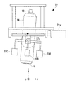
図1,2は、本第1実施形態に係るピーニング装置10の外観図である。図1は、紙面に垂直な方向がy軸、左右方向がx軸、上下方向がz軸とされ、図2は、紙面に垂直な方向がx軸、左右方向がy軸、上下方向がz軸とされる。
ピーニング装置10は、ロボット又はバランサ等の送り装置12に接続されており、自動的に移動し、被加工物の被加工面に打撃を与え、曲げ成形や溶接によって生じた残留応力の低減等を行う。被加工物は、例えばアルミやアルミ合金等の金属である。
なお、ピーニング装置10は、送り装置12に接続されることなく、作業者により保持され、作業者によって移動されてもよい。
1 and 2 are external views of the
The
Note that the
ピーニング装置10の装置本体14の下部、すなわち被加工面と対向する部分には、被加工面に打撃を与えるピーニング打撃ピン16が備えられる。装置本体14は、振動(例えば約20kHz以上の超音波振動)によりピーニング打撃ピン16を被加工面に対して往復運動させる。なお、ピーニング打撃ピン16の形状や往復運動させる方法は限定されない。
A
装置本体14の上部には、装置本体14の振動状態を検出する振動センサ18が備えられている。振動センサ18としては、装置本体14の加速度を検出するセンサが用いられる。また、振動センサ18の位置は一例であり、装置本体14における他の位置に備えられてもよい。
A
装置本体14の側面には、複数のレーザ変位計20(レーザ変位計20A,20B,20C,20D)が備えられている。レーザ変位計20は、一例として装置本体14のz軸を中心として、x軸上で相対する位置に2つとy軸上で相対する位置に2つ備えられている。
これらレーザ変位計20は、装置本体14と被加工面とのなす角度(以下、「装置角度」という。)を検出する角度検出手段として機能する。すなわち、レーザ変位計20は、装置本体14と被加工面との距離を複数箇所で検出することにより、z軸方向を垂直とした装置本体14と被加工面とのなす角度を検出する。
A plurality of laser displacement meters 20 (
These
さらに、装置本体14は、装置本体14の被加工面に対する傾きを調整する傾き調整手段として、x軸を回転軸線としたサーボモータ22xとy軸を回転軸線としたサーボモータ22yが備えられている。
Further, the apparatus
ここで、被加工面は、ピーニングにより時々刻々と形状が変化することに伴い、装置角度が変化し、装置本体14の振動状態が変化する。このため、従来のピーニング装置は、被加工面に対して常に良好(振動の大きい)なピーニングを行えるとは限らない。
そこで、本第1実施形態に係るピーニング装置10が被加工面に対して常に良好なピーニングを行えるように、振動センサ18、レーザ変位計20A,20B,20C,20D、及びサーボモータ22x,22yは、ピーニング装置10が姿勢制御装置30を構成する。
Here, as the shape of the work surface changes from moment to moment due to peening, the device angle changes and the vibration state of the device
Therefore, the
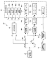
図3は、本第1実施形態に係るピーニング装置10の制御装置40の電気的構成を示すブロック図であり、特に装置本体14の姿勢制御に関する電気的構成を示す。
なお、制御装置40は、主に、例えばCPU(Central Processing Unit)、RAM(Random Access Memory)、及びコンピュータ読み取り可能な記録媒体等から構成されている。そして、後述する角度指令出力部42、減算部44x,44y、姿勢演算部46、及び操作量演算部48x,48y、振動参照波形出力部50、及び振動偏差演算部52の各種機能を実現するための一連の処理は、一例として、プログラムの形式で記録媒体等に記録されており、このプログラムをCPUがRAM等に読み出して、情報の加工・演算処理を実行することにより、各種機能が実現される。
FIG. 3 is a block diagram showing an electrical configuration of the
Note that the
角度指令出力部42は、予め定められた装置角度の指令値(以下、「角度指令値」という。)を出力する。なお、角度指令出力部42は、x方向の角度指令値θxrefを減算部44xへ出力し、y方向の角度指令値θyrefを減算部44yへ出力する。
なお、角度指令値θxref,θyrefは、例えば90度である。
The angle
The angle command values θ xref and θ yref are, for example, 90 degrees.
姿勢演算部46は、レーザ変位計20A,20B,20C,20Dによって検出された距離である変位センサ信号ZA,ZB,ZC,ZDが入力され、これら変位センサ信号ZA,ZB,ZC,ZDに基づいてx方向の装置角度θx及びy方向の装置角度θyを算出する。そして、姿勢演算部46は、装置角度θxを減算部44xへ出力し、装置角度θyを減算部44xへ出力する。
減算部44xは、入力された装置角度θxと角度指令値θxrefとの偏差(以下「x方向角度偏差eθx」という。)を算出し、操作量演算部48xへ出力する。
減算部44yは、入力された装置角度θyと角度指令値θyrefとの偏差(以下「y方向角度偏差eθy」という。)を算出し、操作量演算部48yへ出力する。
The
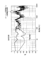
振動参照波形出力部50は、装置本体14の振動状態の参照波形を記憶し、出力する。
図4は、ピーニング装置10の振動状態を表わすグラフの一例である。ピーニング打撃ピン16の振動周波数よりも低い周波数であって、周波数が200Hz以下で、振動が良好な状態と振動が不良な状態とで振動状態が異なる。図4に示されるように良好な振動状態の方が、不良な振動状態に比べてより振動が大きい。
The vibration reference
FIG. 4 is an example of a graph representing the vibration state of the
振動参照波形出力部50は、図4の例に示されるような良好な振動状態の波形を予め定められた参照波形erefとして、振動偏差演算部52へ出力する。
The vibration reference
振動偏差演算部52は、振動センサ18から出力される振動センサ信号Sと参照波形erefとの偏差(以下「振動偏差es」という。)を算出し、操作量演算部48x,48yへ出力する。
なお、振動偏差演算部52は、ローパスフィルタを用いることにより、図4の例で示されるように200Hz以下の周波数、好ましくは100Hz以下の周波数の振動偏差esを算出する。
The vibration
Incidentally, the vibration
操作量演算部48xは、入力されたx方向角度偏差eθxと振動偏差esに基づいて、サーボモータ22xに対する操作量を示す操作量指令値Vxを演算し、サーボアンプ54xへ出力する。なお、操作量演算部48xは、例えば予め定められた関数によって、操作量指令値Vxを演算してもよいし、x方向角度偏差eθxと振動偏差esと操作量指令値Vxとの関係を示したテーブル情報によって、操作量指令値Vxを演算してもよい。
Operation
操作量演算部48yは、入力されたy方向角度偏差eθyと振動偏差esに基づいて、サーボモータ22yに対する操作量を示す操作量指令値Vyを演算し、サーボアンプ54yへ出力する。なお、操作量演算部48yは、例えば予め定められた関数によって、操作量指令値Vyを演算してもよいし、y方向角度偏差eθyと振動偏差esと操作量指令値Vyとの関係を示したテーブル情報によって、操作量指令値Vyを演算してもよい。
Operation
また、操作量指令値Vx,Vyは、例えば電圧値である。 Further, the operation amount command values V x and V y are, for example, voltage values.
サーボアンプ54xは、入力された操作量指令値Vxに基づいてサーボモータ22xを駆動させるための電流ixをサーボモータ22xへ供給する。
サーボモータ22xは、供給された電流ixに応じて回転軸を回転させる。回転軸の回転状態は、エンコーダ56xによって検出される。
The
サーボアンプ54yは、入力された操作量指令値Vyに基づいてサーボモータ22yを駆動させるための電流iyをサーボモータ22yへ供給する。
サーボモータ22yは、供給された電流iyに応じて回転軸を回転させる。回転軸の回転状態は、エンコーダ56yによって検出される。
The
The
このように制御装置40は、検出された装置角度θx,θyと検出された振動センサ信号Sとがフィードバックされ、装置角度θx,θyと予め定められた角度指令値θxref,θyrefとの差分、及び振動センサ信号Sと予め定められた参照波形erefとの差分に基づいて、サーボモータ22x,22yに対する操作量を決定する。
これにより、本第1実施形態に係るピーニング装置10は、装置本体14の振動状態を簡易に良好な振動状態とすることができる。
As described above, the
Thereby, the
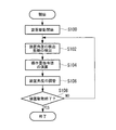
図5は、本第1実施形態に係るピーニング装置10を用いたピーニング処理の流れを示すフローチャートである。
FIG. 5 is a flowchart showing the flow of the peening process using the
まず、ステップ100では、ピーニング装置10の駆動を開始する。これにより、ピーニング打撃ピン16による被加工面への打撃が開始される。
なお、ピーニング装置10による被加工面への押圧力は、ピーニング装置が姿勢制御装置30を備えない場合に比べて弱く、例えば5〜10kgである。ピーニング装置10が送り装置12に接続される場合は、例えば、送り装置12とピーニング装置10との間に設けられたバネにより付勢され、被加工面へ上記押圧力を生じさせる。
First, in
In addition, the pressing force to the to-be-processed surface by the
次のステップ102では、レーザ変位計20A,20B,20C,20Dによる検出結果に基づいて、姿勢演算部46が装置角度θx,θyを検出し、振動センサ18が装置本体14の振動を検出する。
In the next step 102, based on the detection results by the
次のステップ104では、装置角度θx,θy及び振動センサ信号Sのフィードバックによって、操作量演算部48xが操作量指令値Vxを算出し、操作量演算部48yが操作量指令値Vyを算出する。 In the next step 104, the manipulated variable calculator 48 x calculates the manipulated variable command value V x by the feedback of the device angles θ x and θ y and the vibration sensor signal S, and the manipulated variable calculator 48 y detects the manipulated variable command value V y. Is calculated.
次のステップ106では、サーボアンプ54xが操作量指令値Vxに基づいた電流Ixをサーボモータ22xへ供給し、サーボモータ22xの回転軸をx軸回りに回転させる。これにより、図6に示されるように、装置本体14がx軸回りに回動する。また、サーボアンプ54yが操作量指令値Vyに基づいた電流Iyをサーボモータ22yへ供給し、サーボモータ22yの回転軸をy軸回りに回転させる。これにより、図7に示されるように、装置本体14がy軸回りに回動する。
In the next step 106, the current I x servo amplifier 54x is based on the operation amount command value V x is supplied to the
このように、装置本体14の振動状態が参照波形erefにより示される良好な振動状態となるように、サーボモータ22x,22yが装置本体14の被加工面に対する傾きを調整するので、本第1実施形態に係るピーニング装置10は、ピーニングにより時々刻々と形状が変化している被加工面に追従して、良好なピーニングを行うことができる。
As described above, the
次のステップ108では、ピーニング装置10の駆動停止が指示されたか否かを判定し、肯定判定の場合は、本ピーニング処理を終了し、否定判定の場合は、ステップ102へ移行して被加工面に対するピーニングを継続する。
In the next step 108, it is determined whether or not the stop of driving of the
以上説明したように、本第1実施形態に係るピーニング装置10は、被加工面に打撃を与えるピーニング打撃ピン16と、ピーニング打撃ピン16を振動により被加工面に対して往復運動させる装置本体14と、装置本体14の被加工面に対する傾きを調整するサーボモータ22x,22yと、装置角度を検出するレーザ変位計20A,20B,20C,20Dと、装置本体14の振動状態を検出する振動センサ18とを備える。そして、ピーニング装置10の制御装置40は、振動センサ18によって検出された振動状態が予め定められた振動状態となるように、サーボモータ22x,22yを制御する。
従って、本第1実施形態に係るピーニング装置10は、ピーニングにより時々刻々と形状が変化している被加工面に追従して、良好なピーニングを行うことができる。
As described above, the
Therefore, the
〔第2実施形態〕
以下、本発明の第2実施形態について説明する。
[Second Embodiment]
Hereinafter, a second embodiment of the present invention will be described.
なお、本第2実施形態に係るピーニング装置10の構成は、図1に示す第1実施形態に係るピーニング装置10の構成と同様であるので説明を省略する。
The configuration of the
図8は、本第2実施形態に係るピーニング装置10の制御装置40の電気的構成を示すブロック図であり、特に姿勢制御に関する電気的構成を示す。なお、図8における図3と同一の構成部分については図3と同一の符号を付して、その説明を省略する。
FIG. 8 is a block diagram showing an electrical configuration of the
本第2実施形態に係るピーニング装置10は、図8に示されるように、振動センサ18による検出結果に基づいてフィードバックを行わない。すなわち、制御装置40は、レーザ変位計20A,20B,20C,20Dによる検出結果に基づいたフィードバックのみを行い、操作量指令値Vx,Vyを演算する。
なお、振動センサ18による検出結果は、別途モニタされ、装置本体14の振動状態が良好な振動状態であるか否かが作業者等によって判断される。
The
The detection result by the
図9は、本第2実施形態に係るピーニング処理の流れを示すフローチャートである。なお、図9における図5と同一のステップについては図5と同一の符号を付して、その説明を一部又は全部省略する。 FIG. 9 is a flowchart showing the flow of the peening process according to the second embodiment. In FIG. 9, the same steps as those in FIG. 5 are denoted by the same reference numerals as those in FIG.
まず、ステップ100でピーニング装置10の駆動が開始されると、ステップ102’へ移行する。
First, when driving of the
ステップ102’では、レーザ変位計20A,20B,20C,20Dによる検出結果に基づいて、姿勢演算部46が装置角度θx,θyを検出する。
In step 102 ′, the
次のステップ104’では、装置角度θx,θyのフィードバックによって、操作量演算部48xが操作量指令値Vxを算出し、操作量演算部48yが操作量指令値Vyを算出し、ステップ106へ移行する。
In the next step 104 ′, the manipulated
ステップ106では、サーボアンプ54xが操作量指令値Vxに基づいた電流Ixをサーボモータ22xへ供給し、サーボアンプ54yが操作量指令値Vyに基づいた電流Iyをサーボモータ22yへ供給する。
In step 106, the current I x servo amplifier 54x is based on the operation amount command value V x is supplied to the
次のステップ108では、ピーニング装置10の駆動停止が指示されたか否かを判定し、肯定判定の場合は、本ピーニング処理を終了し、否定判定の場合は、ステップ102’へ移行して被加工面に対するピーニングを継続する。
In the next step 108, it is determined whether or not an instruction to stop driving the
以上説明したように、本第2実施形態に係るピーニング装置10は、被加工面に打撃を与えるピーニング打撃ピン16と、ピーニング打撃ピン16を振動により被加工面に対して往復運動させる装置本体14と、装置本体14の被加工面に対する傾きを調整するサーボモータ22x,22yと、装置角度を検出するレーザ変位計20A,20B,20C,20Dとを備える。そして、ピーニング装置10の制御装置40は、レーザ変位計20A,20B,20C,20Dによって検出された装置角度が予め定められた装置角度となるように、サーボモータ22x,22yを制御する。
従って、本第2実施形態に係るピーニング装置10は、ピーニングにより時々刻々と形状が変化している被加工面に追従して、良好なピーニングを行うことができる。
As described above, the
Therefore, the
〔第3実施形態〕
以下、本発明の第3実施形態について説明する。
[Third Embodiment]
Hereinafter, a third embodiment of the present invention will be described.
図10,11は、本第3実施形態に係るピーニング装置10の外観図である。図10は、紙面に垂直な方向がy軸、左右方向がx軸、上下方向がz軸とされ、図11は、紙面に垂直な方向がx軸、左右方向がy軸、上下方向がz軸とされる。
本第3実施形態に係るピーニング装置10は、第1実施形態に係るピーニング装置10とは異なり、レーザ変位計20A,20B,20C,20Dを備えておらず、その他図10,11における図1,2と同一の構成部分については図1,2と同一の符号を付して、その説明を省略する。
10 and 11 are external views of the
Unlike the
図12は、本第3実施形態に係るピーニング装置10の制御装置40の電気的構成を示すブロック図であり、特に姿勢制御に関する電気的構成を示す。なお、図12における図3と同一の構成部分については図3と同一の符号を付して、その説明を省略する。
FIG. 12 is a block diagram showing an electrical configuration of the
本第3実施形態に係る制御装置40は、図12に示されるように、振動センサ18による検出結果に基づいたフィードバックを行い、操作量指令値Vx,Vyを演算する。
As shown in FIG. 12, the
また、エンコーダ56xは、サーボモータ22xの回転軸の回転角度θMxを検出し、操作量演算部48xへ出力する。
The
操作量演算部48xは、回転角度θMxに基づいて装置角度θxを算出し、算出した装置角度θxと角度指令値θxrefとの偏差であるx方向角度偏差eθxを算出する。
そして、操作量演算部48xは、算出したx方向角度偏差eθxと振動偏差esに基づいて、サーボモータ22xに対する操作量を示す操作量指令値Vxを演算し、サーボアンプ54xへ出力する。
Operation
Then, the operation
エンコーダ56yは、サーボモータ22yの回転軸の回転角度θMyを検出し、操作量演算部48yへ出力する。
The
操作量演算部48yは、回転角度θMyに基づいて装置角度θyを算出し、算出した装置角度θyと角度指令値θyrefとの偏差であるy方向角度偏差eθyを算出する。
そして、操作量演算部48yは、算出したy方向角度偏差eθyと振動偏差esに基づいて、サーボモータ22yに対する操作量を示す操作量指令値Vyを演算し、サーボアンプ54yへ出力する。
Operation
Then, the operation
このように、本第3実施形態に係る制御装置40は、サーボモータ22x,yの回転角度θMx,θMy及び振動センサ信号Sがフィードバックされ、回転角度θMx,θMyに基づいて算出した装置角度θx,θyと角度指令値θxref,θyrefとの差分、及び振動センサ信号Sと予め定められた参照波形erefとの差分に基づいて、サーボモータ22x,22yに対する操作量を決定する。
As described above, the
図13は、本第3実施形態に係るピーニング処理の流れを示すフローチャートである。なお、図13における図5と同一のステップについては図5と同一の符号を付して、その説明を一部又は全部省略する。 FIG. 13 is a flowchart showing the flow of the peening process according to the third embodiment. In FIG. 13, the same steps as those in FIG. 5 are denoted by the same reference numerals as those in FIG.
まず、ステップ100でピーニング装置10の駆動が開始されると、ステップ102”へ移行する。
First, when the driving of the
ステップ102”では、操作量演算部48x,48yがサーボモータ22x,yの回転角度θMx,θMyに基づいて装置角度θx,θyを算出し、振動センサ18が装置本体14の振動を検出する。
In step 102 ″, the operation
次のステップ104”では、算出した装置角度θx,θy及び検出した振動センサ信号Sのフィードバックによって、操作量演算部48xが操作量指令値Vxを算出し、操作量演算部48yが操作量指令値Vyを算出し、ステップ106へ移行する。
In the next step 104 ″, the manipulated
ステップ106では、サーボアンプ54xが操作量指令値Vxに基づいた電流Ixをサーボモータ22xへ供給し、サーボアンプ54yが操作量指令値Vyに基づいた電流Iyをサーボモータ22yへ供給する。
In step 106, the current I x servo amplifier 54x is based on the operation amount command value V x is supplied to the
次のステップ108では、ピーニング装置10の駆動停止が指示されたか否かを判定し、肯定判定の場合は、本ピーニング処理を終了し、否定判定の場合は、ステップ102”へ移行して被加工面に対するピーニングを継続する。
In the next step 108, it is determined whether or not an instruction to stop the driving of the
以上説明したように、本第3実施形態に係るピーニング装置10は、被加工面に打撃を与えるピーニング打撃ピン16と、ピーニング打撃ピン16を振動により被加工面に対して往復運動させる装置本体14と、装置本体14の被加工面に対する傾きを調整するサーボモータ22x,22yと装置本体14の振動状態を検出する振動センサ18とを備える。そして、ピーニング装置10の制御装置40は、振動センサ18によって検出された振動状態が予め定められた振動状態となるように、サーボモータ22x,22yを制御する。
従って、本第3実施形態に係るピーニング装置10は、ピーニングにより時々刻々と形状が変化している被加工面に追従して、良好なピーニングを行うことができる。
As described above, the
Therefore, the
なお、本第3実施形態では、サーボモータ22x,yの回転角度θMx,θMyに基づいた装置角度θx,θyも用いてフィードバックする形態について説明したが、回転角度θMx,θMyに基づいた装置角度θx,θyは用いずに、振動センサ18によって検出された振動状態のみをフィードバックする形態としてもよい。
In the third embodiment, the feedback using the device angles θ x and θ y based on the rotation angles θ Mx and θ My of the
〔第4実施形態〕
以下、本発明の第4実施形態について説明する。
[Fourth Embodiment]
The fourth embodiment of the present invention will be described below.
本第4実施形態に係るピーニング装置10の構成は、図1に示す第1実施形態に係るピーニング装置10の構成と同様であるので説明を省略する。
The configuration of the
図14は、本第4実施形態に係るピーニング装置10の制御装置40の電気的構成を示すブロック図であり、特に姿勢制御に関する電気的構成を示す。なお、図14における図3と同一の構成部分については図3と同一の符号を付して、その説明を省略する。
FIG. 14 is a block diagram showing an electrical configuration of the
図14に示されるように、本第4実施形態に係る制御装置40は、参照波形比較部60を備えている。参照波形比較部60は、振動参照波形出力部50に記憶されている参照波形erefと振動センサ18から出力される振動センサ信号Sとを比較する。参照波形erefよりも振動センサ信号Sが大きい場合、参照波形erefは、検出された振動センサ信号Sに更新される。
As shown in FIG. 14, the
その後、制御装置40は、振動センサ18によって検出された振動状態が更新された参照波形erefはとなるように、サーボモータ22x,22yを制御する。
Thereafter, the
従って、本第4実施形態に係るピーニング装置10は、振動状態をより大きくできるので、より良好なピーニングを行うことができる。
Therefore, since the
以上、本発明を、上記各実施形態を用いて説明したが、本発明の技術的範囲は上記実施形態に記載の範囲には限定されない。発明の要旨を逸脱しない範囲で上記各実施形態に多様な変更又は改良を加えることができ、該変更又は改良を加えた形態も本発明の技術的範囲に含まれる。 As mentioned above, although this invention was demonstrated using said each embodiment, the technical scope of this invention is not limited to the range as described in the said embodiment. Various changes or improvements can be added to the above-described embodiments without departing from the gist of the invention, and embodiments to which the changes or improvements are added are also included in the technical scope of the present invention.
例えば、上記各実施形態では、装置本体14の振動状態を検出する振動検出手段として、装置本体14の加速度を検出する振動センサ18を備える形態について説明したが、本発明は、これに限定されるものではなく、装置本体14の振動状態とピーニングにより発せられる音とは相関関係があるため、振動検出手段として音センサ(マイクロホン)を用いる形態としてもよい。音センサは、必ずしも装置本体14に備えられる必要はなく、被加工面の近傍に設けられていてもよい。
For example, in each of the above-described embodiments, the description has been given of the form in which the
また、上記各実施形態で説明したピーニング処理の流れも一例であり、本発明の主旨を逸脱しない範囲内において不要なステップを削除したり、新たなステップを追加したり、処理順序を入れ替えたりしてもよい。 The flow of the peening process described in each of the above embodiments is also an example, and unnecessary steps may be deleted, new steps may be added, or the processing order may be changed within the scope not departing from the gist of the present invention. May be.
10 ピーニング装置
16 ピーニング打撃ピン
18 振動センサ
20 レーザ変位計
22x サーボモータ
22y サーボモータ
40 制御装置
DESCRIPTION OF
Claims (8)
前記打撃手段を被加工面に対して往復運動させる装置本体と、
前記装置本体の前記被加工面に対する傾きを調整する傾き調整手段と、
前記装置本体の振動状態を検出する振動検出手段と、
前記振動検出手段によって検出された振動状態が予め定められた振動状態となるように、前記傾き調整手段を制御する制御手段と、
を備え、
前記予め定められた振動状態よりも前記振動検出手段で検出された振動状態が大きい場合、前記予め定められた振動状態は、検出された該振動状態に更新されるピーニング装置。 Striking means for striking the work surface;
An apparatus main body for reciprocating the striking means with respect to the work surface;
An inclination adjusting means for adjusting an inclination of the apparatus main body with respect to the processing surface;
Vibration detecting means for detecting a vibration state of the apparatus body;
Control means for controlling the inclination adjusting means so that the vibration state detected by the vibration detection means becomes a predetermined vibration state;
Equipped with a,
A peening apparatus in which the predetermined vibration state is updated to the detected vibration state when the vibration state detected by the vibration detection means is larger than the predetermined vibration state .
前記制御手段は、前記モータの回転角度に基づいて前記装置本体と前記被加工面とのなす角度を算出し、算出した角度と予め定められた角度との差分、及び前記振動検出手段によって検出された振動状態と前記予め定められた振動状態との差分に基づいて、前記傾き調整手段に対する操作量を決定する請求項1記載のピーニング装置。 The inclination adjusting means is a motor that rotates the apparatus main body around a predetermined axis,
The control means calculates an angle formed between the apparatus main body and the surface to be processed based on a rotation angle of the motor, and a difference between the calculated angle and a predetermined angle is detected by the vibration detection means. The peening apparatus according to claim 1, wherein an operation amount with respect to the inclination adjusting unit is determined based on a difference between the vibration state and the predetermined vibration state.
前記打撃手段を振動により被加工面に対して往復運動させる装置本体と、
前記装置本体の前記被加工面に対する傾きを調整する傾き調整手段と、
前記装置本体と前記被加工面とのなす角度を検出する角度検出手段と、
前記装置本体の振動状態を検出する振動検出手段と、
前記角度検出手段によって検出された角度が予め定められた角度となるように、前記振動検出手段によって検出された振動状態に基づいて前記傾き調整手段を制御する制御手段と、
を備え、
前記予め定められた振動状態よりも前記振動検出手段で検出された振動状態が大きい場合、前記予め定められた振動状態は、検出された該振動状態に更新されるピーニング装置。 Striking means for striking the work surface;
An apparatus main body for reciprocating the striking means with respect to the work surface by vibration;
An inclination adjusting means for adjusting an inclination of the apparatus main body with respect to the processing surface;
An angle detection means for detecting an angle formed between the apparatus main body and the processing surface;
Vibration detecting means for detecting a vibration state of the apparatus body;
Control means for controlling the tilt adjustment means based on the vibration state detected by the vibration detection means so that the angle detected by the angle detection means becomes a predetermined angle;
Equipped with a,
A peening apparatus in which the predetermined vibration state is updated to the detected vibration state when the vibration state detected by the vibration detection means is larger than the predetermined vibration state .
前記振動検出手段によって前記装置本体の振動状態を検出する第1工程と、
検出した振動状態が予め定められた振動状態となるように、前記傾き調整手段を制御する第2工程と、
を含み、
前記予め定められた振動状態よりも前記振動検出手段で検出された振動状態が大きい場合、前記予め定められた振動状態は、検出された該振動状態に更新されるピーニング方法。 A striking means for striking a work surface; a device main body for reciprocating the striking means with respect to the work surface; a tilt adjusting means for adjusting a tilt of the device main body with respect to the work surface; A peening method of a peening apparatus comprising: a vibration detection means for detecting a vibration state,
A first step of detecting a vibration state of the apparatus main body by the vibration detection means;
A second step of controlling the tilt adjusting means so that the detected vibration state becomes a predetermined vibration state;
Only including,
A peening method in which the predetermined vibration state is updated to the detected vibration state when the vibration state detected by the vibration detection unit is larger than the predetermined vibration state .
前記角度検出手段によって、前記装置本体と前記被加工面とのなす角度を検出すると共に、前記振動検出手段によって、前記装置本体の振動状態を検出する第1工程と、
検出した角度が予め定められた角度となるように、前記振動検出手段によって検出された振動状態に基づいて前記傾き調整手段を制御する第2工程と、
を含み、
前記予め定められた振動状態よりも前記振動検出手段で検出された振動状態が大きい場合、前記予め定められた振動状態は、検出された該振動状態に更新されるピーニング方法。 A striking means for striking the work surface, a device main body for reciprocating the striking means with respect to the work surface by vibration, a tilt adjusting means for adjusting a tilt of the device main body with respect to the work surface, and the device A peening method for a peening apparatus comprising: an angle detection means for detecting an angle formed by a main body and the surface to be processed; and a vibration detection means for detecting a vibration state of the apparatus main body ,
A first step of detecting an angle between the apparatus main body and the surface to be processed by the angle detection means, and detecting a vibration state of the apparatus main body by the vibration detection means ;
A second step of controlling the tilt adjusting means based on the vibration state detected by the vibration detecting means so that the detected angle becomes a predetermined angle;
Only including,
A peening method in which the predetermined vibration state is updated to the detected vibration state when the vibration state detected by the vibration detection unit is larger than the predetermined vibration state .
Priority Applications (5)
| Application Number | Priority Date | Filing Date | Title |
|---|---|---|---|
| JP2012225321A JP6138450B2 (en) | 2012-10-10 | 2012-10-10 | Peening apparatus and peening method |
| PCT/JP2013/077437 WO2014057961A1 (en) | 2012-10-10 | 2013-10-09 | Peening device and peening method |
| US14/433,552 US9889488B2 (en) | 2012-10-10 | 2013-10-09 | Peening device and peening method |
| CA2887011A CA2887011C (en) | 2012-10-10 | 2013-10-09 | Peening device and peening method |
| EP13844919.4A EP2907599B1 (en) | 2012-10-10 | 2013-10-09 | Peening device and peening method |
Applications Claiming Priority (1)
| Application Number | Priority Date | Filing Date | Title |
|---|---|---|---|
| JP2012225321A JP6138450B2 (en) | 2012-10-10 | 2012-10-10 | Peening apparatus and peening method |
Publications (2)
| Publication Number | Publication Date |
|---|---|
| JP2014076466A JP2014076466A (en) | 2014-05-01 |
| JP6138450B2 true JP6138450B2 (en) | 2017-05-31 |
Family
ID=50477429
Family Applications (1)
| Application Number | Title | Priority Date | Filing Date |
|---|---|---|---|
| JP2012225321A Active JP6138450B2 (en) | 2012-10-10 | 2012-10-10 | Peening apparatus and peening method |
Country Status (5)
| Country | Link |
|---|---|
| US (1) | US9889488B2 (en) |
| EP (1) | EP2907599B1 (en) |
| JP (1) | JP6138450B2 (en) |
| CA (1) | CA2887011C (en) |
| WO (1) | WO2014057961A1 (en) |
Families Citing this family (5)
| Publication number | Priority date | Publication date | Assignee | Title |
|---|---|---|---|---|
| JP6949503B2 (en) * | 2017-02-15 | 2021-10-13 | 三菱重工業株式会社 | Parts manufacturing system and parts manufacturing method |
| JP7126055B2 (en) * | 2018-11-29 | 2022-08-26 | 株式会社アドウェルズ | Ultrasonic processing equipment |
| CN111089809B (en) * | 2019-12-23 | 2022-05-27 | 台州市椒江建设工程质量检测中心有限公司 | Drop hammer impact tester control system |
| TWI773220B (en) * | 2020-03-26 | 2022-08-01 | 日商日本製鐵股份有限公司 | Bead blasting device, bead blasting method, and manufacturing method of structure |
| CN115505690B (en) * | 2022-10-25 | 2023-11-14 | 华北电力大学 | Tensioning device for thermal-magnetic vibration composite aging |
Family Cites Families (9)
| Publication number | Priority date | Publication date | Assignee | Title |
|---|---|---|---|---|
| JPH04146043A (en) * | 1990-10-08 | 1992-05-20 | Toshiba Corp | Nc control device for three dimensional surface cutting machine |
| SE516720C2 (en) * | 1999-04-01 | 2002-02-19 | Abb Ab | Equipment for controlling an industrial robot and a procedure for programming and / or adjusting the movement of the robot |
| JP2006095598A (en) * | 2004-08-30 | 2006-04-13 | Nippon Steel Corp | Apparatus, system and method for performing impact plastic working of metal structural body, and program and storage medium |
| JP4831807B2 (en) | 2005-06-14 | 2011-12-07 | 三菱重工業株式会社 | Ultrasonic shot peening apparatus and ultrasonic shot peening method |
| KR100894499B1 (en) * | 2008-05-14 | 2009-04-22 | (주)디자인메카 | The bearing processing system using an ultrasonic nano crystal surface modifier and processing method using the same |
| JP4987816B2 (en) * | 2008-07-28 | 2012-07-25 | 新日本製鐵株式会社 | Automatic impact processing method and automatic impact processing apparatus for improving the fatigue characteristics of welded joints |
| US8224492B2 (en) * | 2008-09-30 | 2012-07-17 | Lakomiak Jason E | Auto-configuring condition monitoring system and method |
| JP4952856B1 (en) * | 2011-07-19 | 2012-06-13 | Jfeエンジニアリング株式会社 | Hitting treatment method and apparatus |
| US9789582B2 (en) * | 2012-07-05 | 2017-10-17 | Surface Technology Holdings Ltd. | Method and compression apparatus for introducing residual compression into a component having a regular or an irregular shaped surface |
-
2012
- 2012-10-10 JP JP2012225321A patent/JP6138450B2/en active Active
-
2013
- 2013-10-09 WO PCT/JP2013/077437 patent/WO2014057961A1/en active Application Filing
- 2013-10-09 EP EP13844919.4A patent/EP2907599B1/en not_active Not-in-force
- 2013-10-09 US US14/433,552 patent/US9889488B2/en active Active
- 2013-10-09 CA CA2887011A patent/CA2887011C/en not_active Expired - Fee Related
Also Published As
| Publication number | Publication date |
|---|---|
| US20150258596A1 (en) | 2015-09-17 |
| EP2907599A4 (en) | 2015-11-04 |
| JP2014076466A (en) | 2014-05-01 |
| US9889488B2 (en) | 2018-02-13 |
| EP2907599B1 (en) | 2019-06-12 |
| EP2907599A1 (en) | 2015-08-19 |
| CA2887011A1 (en) | 2014-04-17 |
| WO2014057961A1 (en) | 2014-04-17 |
| CA2887011C (en) | 2018-01-02 |
Similar Documents
| Publication | Publication Date | Title |
|---|---|---|
| JP6138450B2 (en) | Peening apparatus and peening method | |
| JP5480198B2 (en) | Spot welding robot with learning control function | |
| KR100621100B1 (en) | method and system for teaching welding robot | |
| JP4233584B2 (en) | Spot welding robot positioning method | |
| US20170008171A1 (en) | Robot controller for robot which sets two objects in combined state | |
| JP6240133B2 (en) | Spot welding system that measures the position of the spot where welding is performed | |
| US20170334068A1 (en) | Robot | |
| JP5823278B2 (en) | Weld bead shaping device and shaping method thereof | |
| JP2011167817A (en) | Robot having learning control function | |
| WO2005075157A1 (en) | Method in infustrial robot system | |
| TWI469500B (en) | Mirror angular-positioning apparatus and processing apparatus | |
| JP2010069585A (en) | Device and method for detecting collision, and device for controlling robot | |
| JP6771288B2 (en) | Welding equipment and control method of welding equipment | |
| CN106994545B (en) | Setting support device and setting support method | |
| JP2010231575A (en) | Device and method for instruction of off-line of robot, and robot system | |
| US20190184577A1 (en) | Robot system | |
| JP2019150857A (en) | Adjustment method for workpiece posture, and method of and device for producing molded material | |
| CN110154043B (en) | Robot system for learning control based on machining result and control method thereof | |
| KR20190104362A (en) | Arc point adjustment rod mounting structure, articulated welding robot and welding device | |
| JP5215065B2 (en) | Vibration control system for machine tools | |
| JP2011045934A (en) | Arc welding robot and weaving method of the same | |
| JP2024009167A (en) | Controller | |
| JP2008080343A (en) | Arc sensor | |
| JP2014030841A (en) | Arc following welding method and welding device | |
| JP2015104789A (en) | Robot |
Legal Events
| Date | Code | Title | Description |
|---|---|---|---|
| A621 | Written request for application examination |
Free format text: JAPANESE INTERMEDIATE CODE: A621 Effective date: 20151006 |
|
| A131 | Notification of reasons for refusal |
Free format text: JAPANESE INTERMEDIATE CODE: A131 Effective date: 20160906 |
|
| A521 | Written amendment |
Free format text: JAPANESE INTERMEDIATE CODE: A523 Effective date: 20161107 |
|
| TRDD | Decision of grant or rejection written | ||
| A01 | Written decision to grant a patent or to grant a registration (utility model) |
Free format text: JAPANESE INTERMEDIATE CODE: A01 Effective date: 20170328 |
|
| A61 | First payment of annual fees (during grant procedure) |
Free format text: JAPANESE INTERMEDIATE CODE: A61 Effective date: 20170426 |
|
| R150 | Certificate of patent or registration of utility model |
Ref document number: 6138450 Country of ref document: JP Free format text: JAPANESE INTERMEDIATE CODE: R150 |